EP4560784A1 - Battery and electric device - Google Patents
Battery and electric device Download PDFInfo
- Publication number
- EP4560784A1 EP4560784A1 EP22955942.2A EP22955942A EP4560784A1 EP 4560784 A1 EP4560784 A1 EP 4560784A1 EP 22955942 A EP22955942 A EP 22955942A EP 4560784 A1 EP4560784 A1 EP 4560784A1
- Authority
- EP
- European Patent Office
- Prior art keywords
- heat exchange
- battery
- component
- exchange component
- top cover
- Prior art date
- Legal status (The legal status is an assumption and is not a legal conclusion. Google has not performed a legal analysis and makes no representation as to the accuracy of the status listed.)
- Pending
Links
Images



Classifications
-
- H—ELECTRICITY
- H01—ELECTRIC ELEMENTS
- H01M—PROCESSES OR MEANS, e.g. BATTERIES, FOR THE DIRECT CONVERSION OF CHEMICAL ENERGY INTO ELECTRICAL ENERGY
- H01M10/00—Secondary cells; Manufacture thereof
- H01M10/60—Heating or cooling; Temperature control
- H01M10/65—Means for temperature control structurally associated with the cells
- H01M10/655—Solid structures for heat exchange or heat conduction
- H01M10/6556—Solid parts with flow channel passages or pipes for heat exchange
-
- B—PERFORMING OPERATIONS; TRANSPORTING
- B60—VEHICLES IN GENERAL
- B60K—ARRANGEMENT OR MOUNTING OF PROPULSION UNITS OR OF TRANSMISSIONS IN VEHICLES; ARRANGEMENT OR MOUNTING OF PLURAL DIVERSE PRIME-MOVERS IN VEHICLES; AUXILIARY DRIVES FOR VEHICLES; INSTRUMENTATION OR DASHBOARDS FOR VEHICLES; ARRANGEMENTS IN CONNECTION WITH COOLING, AIR INTAKE, GAS EXHAUST OR FUEL SUPPLY OF PROPULSION UNITS IN VEHICLES
- B60K1/00—Arrangement or mounting of electrical propulsion units
- B60K1/04—Arrangement or mounting of electrical propulsion units of the electric storage means for propulsion
-
- B—PERFORMING OPERATIONS; TRANSPORTING
- B60—VEHICLES IN GENERAL
- B60L—PROPULSION OF ELECTRICALLY-PROPELLED VEHICLES; SUPPLYING ELECTRIC POWER FOR AUXILIARY EQUIPMENT OF ELECTRICALLY-PROPELLED VEHICLES; ELECTRODYNAMIC BRAKE SYSTEMS FOR VEHICLES IN GENERAL; MAGNETIC SUSPENSION OR LEVITATION FOR VEHICLES; MONITORING OPERATING VARIABLES OF ELECTRICALLY-PROPELLED VEHICLES; ELECTRIC SAFETY DEVICES FOR ELECTRICALLY-PROPELLED VEHICLES
- B60L50/00—Electric propulsion with power supplied within the vehicle
- B60L50/50—Electric propulsion with power supplied within the vehicle using propulsion power supplied by batteries or fuel cells
- B60L50/60—Electric propulsion with power supplied within the vehicle using propulsion power supplied by batteries or fuel cells using power supplied by batteries
- B60L50/64—Constructional details of batteries specially adapted for electric vehicles
-
- B—PERFORMING OPERATIONS; TRANSPORTING
- B60—VEHICLES IN GENERAL
- B60L—PROPULSION OF ELECTRICALLY-PROPELLED VEHICLES; SUPPLYING ELECTRIC POWER FOR AUXILIARY EQUIPMENT OF ELECTRICALLY-PROPELLED VEHICLES; ELECTRODYNAMIC BRAKE SYSTEMS FOR VEHICLES IN GENERAL; MAGNETIC SUSPENSION OR LEVITATION FOR VEHICLES; MONITORING OPERATING VARIABLES OF ELECTRICALLY-PROPELLED VEHICLES; ELECTRIC SAFETY DEVICES FOR ELECTRICALLY-PROPELLED VEHICLES
- B60L50/00—Electric propulsion with power supplied within the vehicle
- B60L50/50—Electric propulsion with power supplied within the vehicle using propulsion power supplied by batteries or fuel cells
- B60L50/60—Electric propulsion with power supplied within the vehicle using propulsion power supplied by batteries or fuel cells using power supplied by batteries
- B60L50/66—Arrangements of batteries
-
- H—ELECTRICITY
- H01—ELECTRIC ELEMENTS
- H01M—PROCESSES OR MEANS, e.g. BATTERIES, FOR THE DIRECT CONVERSION OF CHEMICAL ENERGY INTO ELECTRICAL ENERGY
- H01M10/00—Secondary cells; Manufacture thereof
- H01M10/42—Methods or arrangements for servicing or maintenance of secondary cells or secondary half-cells
- H01M10/425—Structural combination with electronic components, e.g. electronic circuits integrated to the outside of the casing
-
- H—ELECTRICITY
- H01—ELECTRIC ELEMENTS
- H01M—PROCESSES OR MEANS, e.g. BATTERIES, FOR THE DIRECT CONVERSION OF CHEMICAL ENERGY INTO ELECTRICAL ENERGY
- H01M10/00—Secondary cells; Manufacture thereof
- H01M10/60—Heating or cooling; Temperature control
- H01M10/61—Types of temperature control
- H01M10/613—Cooling or keeping cold
-
- H—ELECTRICITY
- H01—ELECTRIC ELEMENTS
- H01M—PROCESSES OR MEANS, e.g. BATTERIES, FOR THE DIRECT CONVERSION OF CHEMICAL ENERGY INTO ELECTRICAL ENERGY
- H01M10/00—Secondary cells; Manufacture thereof
- H01M10/60—Heating or cooling; Temperature control
- H01M10/61—Types of temperature control
- H01M10/615—Heating or keeping warm
-
- H—ELECTRICITY
- H01—ELECTRIC ELEMENTS
- H01M—PROCESSES OR MEANS, e.g. BATTERIES, FOR THE DIRECT CONVERSION OF CHEMICAL ENERGY INTO ELECTRICAL ENERGY
- H01M10/00—Secondary cells; Manufacture thereof
- H01M10/60—Heating or cooling; Temperature control
- H01M10/62—Heating or cooling; Temperature control specially adapted for specific applications
- H01M10/625—Vehicles
-
- H—ELECTRICITY
- H01—ELECTRIC ELEMENTS
- H01M—PROCESSES OR MEANS, e.g. BATTERIES, FOR THE DIRECT CONVERSION OF CHEMICAL ENERGY INTO ELECTRICAL ENERGY
- H01M10/00—Secondary cells; Manufacture thereof
- H01M10/60—Heating or cooling; Temperature control
- H01M10/66—Heat-exchange relationships between the cells and other systems, e.g. central heating systems or fuel cells
- H01M10/667—Heat-exchange relationships between the cells and other systems, e.g. central heating systems or fuel cells the system being an electronic component, e.g. a CPU, an inverter or a capacitor
-
- H—ELECTRICITY
- H01—ELECTRIC ELEMENTS
- H01M—PROCESSES OR MEANS, e.g. BATTERIES, FOR THE DIRECT CONVERSION OF CHEMICAL ENERGY INTO ELECTRICAL ENERGY
- H01M50/00—Constructional details or processes of manufacture of the non-active parts of electrochemical cells other than fuel cells, e.g. hybrid cells
- H01M50/20—Mountings; Secondary casings or frames; Racks, modules or packs; Suspension devices; Shock absorbers; Transport or carrying devices; Holders
- H01M50/204—Racks, modules or packs for multiple batteries or multiple cells
-
- H—ELECTRICITY
- H01—ELECTRIC ELEMENTS
- H01M—PROCESSES OR MEANS, e.g. BATTERIES, FOR THE DIRECT CONVERSION OF CHEMICAL ENERGY INTO ELECTRICAL ENERGY
- H01M50/00—Constructional details or processes of manufacture of the non-active parts of electrochemical cells other than fuel cells, e.g. hybrid cells
- H01M50/20—Mountings; Secondary casings or frames; Racks, modules or packs; Suspension devices; Shock absorbers; Transport or carrying devices; Holders
- H01M50/249—Mountings; Secondary casings or frames; Racks, modules or packs; Suspension devices; Shock absorbers; Transport or carrying devices; Holders specially adapted for aircraft or vehicles, e.g. cars or trains
-
- H—ELECTRICITY
- H01—ELECTRIC ELEMENTS
- H01M—PROCESSES OR MEANS, e.g. BATTERIES, FOR THE DIRECT CONVERSION OF CHEMICAL ENERGY INTO ELECTRICAL ENERGY
- H01M50/00—Constructional details or processes of manufacture of the non-active parts of electrochemical cells other than fuel cells, e.g. hybrid cells
- H01M50/20—Mountings; Secondary casings or frames; Racks, modules or packs; Suspension devices; Shock absorbers; Transport or carrying devices; Holders
- H01M50/271—Lids or covers for the racks or secondary casings
-
- H—ELECTRICITY
- H01—ELECTRIC ELEMENTS
- H01M—PROCESSES OR MEANS, e.g. BATTERIES, FOR THE DIRECT CONVERSION OF CHEMICAL ENERGY INTO ELECTRICAL ENERGY
- H01M50/00—Constructional details or processes of manufacture of the non-active parts of electrochemical cells other than fuel cells, e.g. hybrid cells
- H01M50/20—Mountings; Secondary casings or frames; Racks, modules or packs; Suspension devices; Shock absorbers; Transport or carrying devices; Holders
- H01M50/271—Lids or covers for the racks or secondary casings
- H01M50/273—Lids or covers for the racks or secondary casings characterised by the material
-
- H—ELECTRICITY
- H01—ELECTRIC ELEMENTS
- H01M—PROCESSES OR MEANS, e.g. BATTERIES, FOR THE DIRECT CONVERSION OF CHEMICAL ENERGY INTO ELECTRICAL ENERGY
- H01M50/00—Constructional details or processes of manufacture of the non-active parts of electrochemical cells other than fuel cells, e.g. hybrid cells
- H01M50/50—Current conducting connections for cells or batteries
- H01M50/572—Means for preventing undesired use or discharge
- H01M50/574—Devices or arrangements for the interruption of current
- H01M50/583—Devices or arrangements for the interruption of current in response to current, e.g. fuses
-
- B—PERFORMING OPERATIONS; TRANSPORTING
- B60—VEHICLES IN GENERAL
- B60K—ARRANGEMENT OR MOUNTING OF PROPULSION UNITS OR OF TRANSMISSIONS IN VEHICLES; ARRANGEMENT OR MOUNTING OF PLURAL DIVERSE PRIME-MOVERS IN VEHICLES; AUXILIARY DRIVES FOR VEHICLES; INSTRUMENTATION OR DASHBOARDS FOR VEHICLES; ARRANGEMENTS IN CONNECTION WITH COOLING, AIR INTAKE, GAS EXHAUST OR FUEL SUPPLY OF PROPULSION UNITS IN VEHICLES
- B60K1/00—Arrangement or mounting of electrical propulsion units
- B60K2001/003—Arrangement or mounting of electrical propulsion units with means for cooling the electrical propulsion units
- B60K2001/005—Arrangement or mounting of electrical propulsion units with means for cooling the electrical propulsion units the electric storage means
-
- B—PERFORMING OPERATIONS; TRANSPORTING
- B60—VEHICLES IN GENERAL
- B60K—ARRANGEMENT OR MOUNTING OF PROPULSION UNITS OR OF TRANSMISSIONS IN VEHICLES; ARRANGEMENT OR MOUNTING OF PLURAL DIVERSE PRIME-MOVERS IN VEHICLES; AUXILIARY DRIVES FOR VEHICLES; INSTRUMENTATION OR DASHBOARDS FOR VEHICLES; ARRANGEMENTS IN CONNECTION WITH COOLING, AIR INTAKE, GAS EXHAUST OR FUEL SUPPLY OF PROPULSION UNITS IN VEHICLES
- B60K1/00—Arrangement or mounting of electrical propulsion units
- B60K1/04—Arrangement or mounting of electrical propulsion units of the electric storage means for propulsion
- B60K2001/0405—Arrangement or mounting of electrical propulsion units of the electric storage means for propulsion characterised by their position
- B60K2001/0438—Arrangement under the floor
-
- B—PERFORMING OPERATIONS; TRANSPORTING
- B62—LAND VEHICLES FOR TRAVELLING OTHERWISE THAN ON RAILS
- B62D—MOTOR VEHICLES; TRAILERS
- B62D25/00—Superstructure or monocoque structure sub-units; Parts or details thereof not otherwise provided for
- B62D25/20—Floors or bottom sub-units
-
- H—ELECTRICITY
- H01—ELECTRIC ELEMENTS
- H01M—PROCESSES OR MEANS, e.g. BATTERIES, FOR THE DIRECT CONVERSION OF CHEMICAL ENERGY INTO ELECTRICAL ENERGY
- H01M10/00—Secondary cells; Manufacture thereof
- H01M10/42—Methods or arrangements for servicing or maintenance of secondary cells or secondary half-cells
- H01M10/425—Structural combination with electronic components, e.g. electronic circuits integrated to the outside of the casing
- H01M2010/4271—Battery management systems including electronic circuits, e.g. control of current or voltage to keep battery in healthy state, cell balancing
-
- H—ELECTRICITY
- H01—ELECTRIC ELEMENTS
- H01M—PROCESSES OR MEANS, e.g. BATTERIES, FOR THE DIRECT CONVERSION OF CHEMICAL ENERGY INTO ELECTRICAL ENERGY
- H01M2200/00—Safety devices for primary or secondary batteries
- H01M2200/10—Temperature sensitive devices
- H01M2200/103—Fuse
-
- H—ELECTRICITY
- H01—ELECTRIC ELEMENTS
- H01M—PROCESSES OR MEANS, e.g. BATTERIES, FOR THE DIRECT CONVERSION OF CHEMICAL ENERGY INTO ELECTRICAL ENERGY
- H01M2220/00—Batteries for particular applications
- H01M2220/20—Batteries in motive systems, e.g. vehicle, ship, plane
-
- Y—GENERAL TAGGING OF NEW TECHNOLOGICAL DEVELOPMENTS; GENERAL TAGGING OF CROSS-SECTIONAL TECHNOLOGIES SPANNING OVER SEVERAL SECTIONS OF THE IPC; TECHNICAL SUBJECTS COVERED BY FORMER USPC CROSS-REFERENCE ART COLLECTIONS [XRACs] AND DIGESTS
- Y02—TECHNOLOGIES OR APPLICATIONS FOR MITIGATION OR ADAPTATION AGAINST CLIMATE CHANGE
- Y02E—REDUCTION OF GREENHOUSE GAS [GHG] EMISSIONS, RELATED TO ENERGY GENERATION, TRANSMISSION OR DISTRIBUTION
- Y02E60/00—Enabling technologies; Technologies with a potential or indirect contribution to GHG emissions mitigation
- Y02E60/10—Energy storage using batteries
Definitions
- the present application relates to the technical field of batteries, and in particular, to a battery and an electrical apparatus.
- the traditional top cover only plays the role of protecting the battery cell and has a single function.
- the present application provides a battery and an electrical apparatus, which can alleviate the problem of single function of the top cover.
- the present application provides a battery, wherein the battery comprises a battery cell, a top cover and a power distribution box, the top cover is sandwiched between the battery cell and the power distribution box, and the power distribution box is used to control the battery.
- a heat exchange flow channel is formed in the top cover, and the heat exchange flow channel is used to accommodate a fluid to regulate the temperature of the battery cell and the power distribution box.
- the top cover since a heat exchange flow channel is formed in the top cover, and the heat exchange flow channel can accommodate a fluid for regulating the temperature of the battery cell and the temperature of the power distribution box. Therefore, the top cover not only has the function of protecting the battery cells, but also has the function of cooling or heating the battery cells and the power distribution box. At the same time, compared with traditional batteries, the power distribution box is located outside the box of the battery, which effectively improves the space utilization of the battery.
- the power distribution box is provided with one or more of a fuse, a relay, a current sensor and a BMS battery system inside to facilitate control of the battery.
- the power distribution box is a sealed structure. In this way, liquid can be prevented from entering the power distribution box and damaging the components in the power distribution box.
- the top cover comprises a first heat exchange component and a second heat exchange component, and the first heat exchange component and the second heat exchange component are spliced to form the heat exchange flow channel.
- the first heat exchange component and the second heat exchange component are spliced to form a heat exchange flow channel, which facilitates the formation of the heat exchange flow channel.
- the second heat exchange component is recessed away from the first heat exchange component to form the heat exchange flow channel, thereby facilitating the formation of the heat exchange flow channel.
- the first heat exchange component is a flat plate
- the second heat exchange component includes a first heat exchange sub-component and a second heat exchange sub-component connected to each other, the first heat exchange sub-component is recessed relative to the second heat exchange sub-component in the direction away from the first heat exchange component; the heat exchange flow channel is formed between the first heat exchange sub-component and the first heat exchange component, and the second heat exchange sub-component is in contact with the first heat exchange component.
- the battery cell is connected to a side of the first heat exchange component away from the second heat exchange component.
- the first heat exchange component is a flat plate, so as to facilitate connection with the battery cell.
- the bottom or side wall (other than the terminal post surface) of the battery cell is adhered to the plane of the first heat exchange component away from the first heat exchange component.
- the top cover since the second heat exchange component includes a first heat exchange sub-component and a second heat exchange sub-component which are connected to each other, and the first heat exchange sub-component is recessed relative to the second heat exchange sub-component in the direction away from the first heat exchange component, that is, the second heat exchange component has a concave-convex structure, the top cover has great impact resistance and provides good protection for the battery cells.
- the heat exchange flow channel comprises a plurality of sub-flow channels which communicate with each other.
- the second heat exchange component comprises a plurality of first heat exchange sub-components and a plurality of second heat exchange sub-components, and one of the sub-flow channel is formed between each of the first heat exchange sub-components and the first heat exchange component.
- the heat exchange flow channel comprises a plurality of sub-flow channels
- the fluid flows in the plurality of sub-flow channels to regulate the temperature uniformity of the battery cells and the components of the power distribution box.
- the heat exchange flow channel comprises a plurality of sub-flow channels
- the second heat exchange component comprises a plurality of first heat exchange sub-components and a plurality of second heat exchange sub-components
- the number of concave-convex structures of the second heat exchange component is increased and the impact resistance of the top cover is further improved.
- the thickness of both the first heat exchange component and the second heat exchange component is 0.6 mm to 3 mm.
- the thickness of the first heat exchange component and the second heat exchange component is set to 0.6 mm to 3 mm, which provides a good heat exchange effect while ensuring the strength of both.
- the depth of the flow channel area is 1 to 3 times the thickness of the first heat exchange component; and/or the depth of the heat exchange flow channel is 2 mm to 7 mm.
- the depth of the heat exchange flow channel ensures that the amount of fluid accommodated is appropriate, so that the amount of fluid accommodated is not too small, thereby ensuring the heat exchange effect while avoiding accommodating too much fluid and thus affecting the strength of the top cover.
- the first heat exchange component and the second heat exchange component are fixed by welding or bonding, thus ensuring the fixing effect of the first heat exchange component and the second heat exchange component.
- the material selected for the first heat exchange component is steel or aluminum; and/or the material selected for the second heat exchange component is steel or aluminum. In this way, the heat exchange effect between the first heat exchange component and the second heat exchange component is guaranteed.
- the battery further comprises a frame and a bottom cover, the two ends of the frame respectively form a top opening and a bottom opening, the top cover is mounted on the top of the frame to seal the top opening, the bottom cover is mounted on the bottom of the frame to seal the bottom opening, and the top cover, the frame and the bottom cover define an accommodating space.
- the battery cell is accommodated in the accommodating space.
- the top cover and the bottom cover are respectively mounted on the top and bottom of the frame, so that the height of the entire box of the battery is relatively low, reducing the space occupied by the battery in the height direction.
- the frame includes a frame body and a support beam
- the support beam is connected to the frame body, the frame body and the support beam together form the top opening, and the support beam is arranged below and supports the top cover.
- the support beam since the support beam is arranged below and supports the top cover, it has a good supporting effect on the top cover.
- the present application provides an electrical apparatus comprising the battery according to any of the above embodiments.
- the electrical apparatus is a vehicle
- the top cover is a floor of the vehicle
- the side of the second heat exchange component away from the first heat exchange component is arranged to face the passenger compartment of the vehicle.
- the top cover can not only realize the function of heat exchange with the battery cells, but also heat or cool the passenger compartment to improve the user experience. Since the top cover serves as the floor of the vehicle, the utilization rate of the entire vehicle height is greatly improved, and a battery pack with better energy can be obtained. There is a heat exchange flow channel in the top cover. As the floor of the vehicle, the top cover can better isolate the noise generated by the vehicle underbody.
- the power distribution box is located directly below or behind the rear seats of the vehicle. Placing the power distribution box below or behind the rear seat of the vehicle can greatly utilize the space of the entire vehicle.
- first and second are used for descriptive purposes only, and cannot be construed as indicating or implying relative importance or implicitly indicating the number of technical features indicated. Therefore, a feature defined by “first” or “second” may expressly or implicitly include at least one of the features. In the description of the present application, the meaning of "a plurality of” is at least two, for example two or three, unless otherwise explicitly and specifically defined.
- the terms “mount”, “link”, “connect” and “fix” should be broadly understood, for example, they may be a fixed connection or a detachable connection or be integrated; or may be a mechanical connection or an electrical connection; or may be a direct connection or an indirect connection through an intermediate medium, or may be a communication between the interior of two elements or the interaction of two elements, unless otherwise specifically defined.
- the specific meanings of the above terms in the present application can be understood according to specific situations.
- a first feature being “on” or “under” a second feature may be the case that the first feature is in direct contact with the second feature, or the first feature is in indirect contact with the second feature via an intermediate medium.
- the expression the first feature being “over”, “above” and “on top of” the second feature may be a case that the first feature is directly above or obliquely above the second feature, or only means that the level of the first feature is higher than that of the second feature.
- the expression the first feature being "below”, “underneath” or “under” the second feature may be a case that the first feature is directly underneath or obliquely underneath the second feature, or only means that the level of the first feature is lower than that of the second feature.
- Power batteries are increasingly more widely used.
- Power batteries are not only applied in energy storage power source systems such as water, fire, wind and solar power stations, but also widely applied in electric transport tools, such as electric bicycles, electric motorcycles, and electric vehicles, as well as many fields, such as military equipment and aerospace.
- electric transport tools such as electric bicycles, electric motorcycles, and electric vehicles, as well as many fields, such as military equipment and aerospace.
- military equipment and aerospace As the application fields of the power batteries continue to expand, their market demand is also constantly expanding.
- the traditional top cover only plays the role of protecting the battery cell and has a single function.
- the applicant has found through research that the function of the top cover can be optimized, so that, for example, the top cover can not only protect the battery cells, but also cool or heat the battery cells.
- the battery comprises a cell, a top cover and a power distribution box.
- the top cover is sandwiched between the battery cell and the power distribution box.
- the power distribution box is used to control the voltage of the battery.
- a heat exchange flow channel is formed in the top cover, and the heat exchange flow channel is used to accommodate a fluid for regulating the temperature of the battery cell and the power distribution box.
- the top cover Since a heat exchange flow channel is formed in the top cover, and the heat exchange flow channel can accommodate the fluid for regulating the temperature of the battery cell and the temperature of the power distribution box. Therefore, the top cover not only has the function of protecting the battery cells, but also has the function of cooling or heating the battery cells and the power distribution box. At the same time, compared with traditional batteries, the power distribution box is located outside the battery box, which prevents the exhaust of the battery cells from damaging the components in the power distribution box.
- the battery disclosed in the embodiment of the present application can be used in, but not limited to, electrical apparatus such as vehicles, vessels, or aircrafts.
- the power supply system of an electrical apparatus device can comprise the battery disclosed in the present application, so that the battery cell can be well protected and the heat management of the battery cell can be carried out.
- An embodiment of the present application provides an electrical apparatus using a battery as a power source.
- the electrical apparatus may be, but is not limited to, a mobile phone, a tablet, a laptop, an electric toy, an electric tool, a battery cart, an electric vehicle, a ship, a spacecraft, and the like.
- the electric toy may include a stationary or mobile electric toy, for example, a game console, an electric car toy, an electric ship toy, and an electric aircraft toy, and the like
- the spacecraft may include an aircraft, a rocket, a space shuttle and a spaceship, and the like.
- an electrical apparatus being a vehicle 1000 is taken as an example for the description.
- the vehicle 1000 may be a fuel vehicle, a gas vehicle or a new energy vehicle.
- the new energy vehicle may be an all-electric vehicle, a hybrid vehicle, an extended range electric vehicle, or the like.
- a battery 100 is arranged in the vehicle 1000.
- the battery 100 may be arranged at the bottom or head or tail of the vehicle 1000.
- the battery 100 may be used as a power supply for the vehicle 1000, for example, the battery 100 may be used as an operating power source for the vehicle 1000.
- the vehicle 1000 may further include a controller 200 and a motor 300.
- the controller 200 is configured to control the battery 100 to supply power to the motor 300, for example, to supply power for starting, navigation and driving of the vehicle 1000.
- the battery 100 may not only be used as the operating power source for the vehicle 1000, but also as a driving power source for the vehicle 1000, to replace or partially replace fuel or natural gas to provide driving power for the vehicle 1000.
- the battery 100 includes a box and battery cells 20, the battery cells 20 are accommodated within the box.
- the box may include a first portion and a second portion that cover each other, and the first portion and the second portion jointly define an accommodating space for accommodating the battery cell 20.
- the second portion may be a hollow structure with one end open, and the first portion may be a plate-like structure. In this case, the first portion constitutes the top cover 10 of the battery 100.
- the battery 100 there may be a plurality of battery cells 20, and the plurality of battery cells 20 can be connected in series or in parallel or in parallel-series connection, where the parallel-series connection means that the plurality of battery cells 20 are connected in both series and parallel.
- the plurality of battery cells 20 can be directly connected together in series or in parallel or in parallel-series connection, and then the whole composed of the plurality of battery cells 20 can be accommodated in the box; and of course, the battery 100 may also be in the form of a battery 100 module first formed by the plurality of battery cells 20 being connected in series or in parallel or in parallel-series connection, then a plurality of battery 100 modules can be connected in series or in parallel or in parallel-series connection to form a whole, and accommodated in the box.
- the battery 100 may further comprise other structures, for example, the battery 100 may further include a bus component for realizing electrical connections between the plurality of battery cells 20.
- Each battery cell 20 may be a secondary battery 100 or a primary battery 100; or it may be a lithium-sulfur battery 100, a sodium-ion battery 100 or a magnesium-ion battery 100, but is not limited thereto.
- the battery cells 20 may be cylindrical, flat, rectangular, or in other shapes.
- the battery cell 20 is the smallest unit constituting the battery 100. Referring to FIG. 2 , the battery cell 20 includes an end cover 21, a shell 22, a battery cell assembly 23 and other functional components.
- the end cover 21 is a component that covers an opening of the shell 22 to isolate the internal environment of the battery cell 20 from the external environment.
- the shape of the end cover 21 may be adaptive to the shape of the shell 22 so as to be matched with the shell 22.
- the end cover 21 may be made of a material (such as an aluminum alloy) with a certain hardness and strength, so that the end cover 21 is not easy to be deformed when being pressed and collided, the battery cell 20 can have a higher structural strength, and the safety performance can also be improved.
- Functional components such as electrode terminals 21a may be arranged on the end cover 21. The electrode terminals 21a can be used for being electrically connected to the battery cell assembly 23 for outputting or inputting electric energy of the battery cell 20.
- the end cover 21 may be further provided with a pressure relief mechanism used for relieving internal pressure when the internal pressure or temperature of the battery cell 20 reaches a threshold.
- the end cover 21 may be made of various materials, such as copper, iron, aluminum, stainless steel, an aluminum alloy and plastic, which is not particularly limited in this embodiment of the present application.
- an insulating member may be further arranged on an inner side of the end cover 21 and may be used for isolating an electrical connection component in the shell 22 from the end cover 21, thereby reducing the risk of short circuit.
- the insulating member may be made of plastic, rubber, etc.
- the shell 22 is an assembly used to be matched with the end cover 21 to form the internal environment of the battery cell 20, where the formed internal environment can be used to accommodate the battery cell assembly 23, an electrolyte and other components.
- the shell 22 and the end cover 21 may be separate components, the opening may be formed in the shell 22, and at the opening, the opening is covered with the end cover 21 so as to form the internal environment of the battery cell 20.
- the end cover 21 and the shell 22 may also be integrated.
- the end cover 21 and the shell 22 may form a common connection surface before other components enter the shell.
- the shell 22 is covered with the end cover 21.
- the shell 22 may be in various shapes and sizes, such as a rectangular solid, a cylinder and a hexagonal prism. Specifically, the shape of the shell 22 may be determined according to the specific shape and size of the battery cell assembly 23.
- the shell 22 may be made of various materials, such as copper, iron, aluminum, stainless steel, an aluminum alloy and plastic, which is not particularly limited in this embodiment of the present application.
- the battery cell assembly 23 is a component in which an electrochemical reaction occurs in the battery cell 20.
- One or more battery cell assemblies 23 may be contained within the shell 22.
- the battery cell assembly 23 is mainly formed by winding or stacking a positive electrode plate and a negative electrode plate, and a separator is usually arranged between the positive electrode plate and the negative electrode plate.
- the portions, with active materials, of the positive electrode plate and the negative electrode plate constitute a main body part of the battery cell assembly 23, and the portions, without the active materials, of the positive electrode plate and the negative electrode plate respectively constitute tabs 23a.
- the positive tab and the negative tab may be located at one end of the main body part together or located at two ends of the main body part respectively.
- the positive electrode active material and the negative electrode active material react with the electrolyte solution, and the tabs 23a are connected to the electrode terminals 21a to form a current loop.
- the present application provides a battery 100.
- the battery 100 includes a battery cell 20, a top cover 10 and a power distribution box 50.
- the top cover 10 is sandwiched between the battery cell 20 and the power distribution box 50.
- the power distribution box 50 is used to control the battery 100.
- the power distribution box 50 is used to control the voltage and/or current of the battery 100.
- a heat exchange flow channel 11 is formed in the top cover 10, and the heat exchange flow channel 11 is used to accommodate a fluid to regulate the temperature of the battery cell 20 and the power distribution box 50.
- the top cover 10 is sandwiched between the battery cell 20 and the power distribution box 50 " means that the power distribution box 50, the top cover 10 and the battery cell 20 are stacked, and the top cover 10 is an interlayer between the power distribution box 50 and the battery cell 20 to form a sandwich structure. Specifically, in the height direction of the battery 100, the power distribution box 50, the top cover 10 and the battery cell 20 are stacked.
- the heat exchange flow channel 11 is a passage that can accommodate a fluid for regulating the temperature of the battery cell 20 and the high-voltage box. In the process of cooling or heating the battery cell 20 and the power distribution box 50, the fluid can circulate in the heat exchange flow channel 11 to transfer or take away heat.
- the cross-section of the flow channel can be of various shapes, such as a cuboid, a cylinder, and a hexagonal prism.
- Fluids can be either liquids or gases.
- the liquid is also called a cooling medium.
- the top cover 10 is used to heat the battery cells 20 and the power distribution box 50, the liquid is also called a heating medium.
- the top cover 10 since a heat exchange flow channel 11 is formed in the top cover 10, and the heat exchange flow channel 11 can accommodate a fluid for regulating the temperature of the battery cell 20 and the temperature of the power distribution box 50. Therefore, the top cover 10 not only has the function of protecting the battery cells 20, but also has the function of cooling or heating the battery cells 20 and the power distribution box 50. At the same time, compared with traditional batteries 100, the power distribution box 50 is located outside the box of the battery 100, which effectively improves the space utilization of the battery 100.
- the voltage of the battery 100 is relatively high. If electrical apparatuses and electrical appliances such as the motor controller 200, the air conditioning system and the charging system are directly connected to the battery 100, the wiring harness of the battery 100 will be messy. Therefore, the battery 100 needs to add a high-voltage power distribution box 50 to distribute the high voltage to the battery 100.
- the power distribution box 50 adopts a centralized power distribution solution with a compact structure design, convenient wiring layout, and quick and easy maintenance. According to the system architecture requirements of different customers, the power distribution box 50 also needs to integrate some of the battery 100 management system intelligent control management units, so as to further simplify the complexity of power distribution of the entire electrical apparatus.
- the power distribution box 50 is provided with one or more of a fuse, a relay, a current sensor and a BMS battery system inside to facilitate control of the battery 100.
- the fuse is a kind of electrical appliance that when a current flowing through the fuse exceeds a specified value, the fuse-element fuses with heat generated by itself, thereby disconnecting a circuit.
- the relay is an electrical control device, which is an electrical appliance that, when the change of input quantity (excitation quantity) reaches the specified requirement, causes a predetermined step change in the controlled quantity in the electrical output circuit.
- the current sensor is a detection apparatus that can sense the information of the measured current, convert the detected and sensed information into electrical signals or information in other desired forms conforming to certain standards and requirements according to a certain rule and output them, to meet the requirements for transmitting, processing, storing, displaying, recording, and controlling the information.
- the BMS battery system is commonly called battery nanny or battery housekeeper, mainly used to intelligently manage and maintain the battery units, prevent overcharging and over-discharging of batteries, extend the battery life, and monitor the battery state.
- the power distribution box 50 is a sealed structure. In this way, liquid can be prevented from entering the power distribution box 50 and damaging the components in the power distribution box 50.
- the top cover 10 includes a first heat exchange component 12 and a second heat exchange component 13, and the first heat exchange component 12 and the second heat exchange component 13 are connected to form a heat exchange flow channel 11.
- the first heat exchange component 12 and the second heat exchange component 13 are both components that can exchange heat with external components, that is, the heat of the fluid can be transferred to the first heat exchange component 12 and the second heat exchange component 13, and the first heat exchange component 12 and the second heat exchange component 13 conduct the heat of the fluid to external components, such as the battery cell 20 and the components of the power distribution box 50.
- the first heat exchange component 12 and the second heat exchange component 13 are both made of metal.
- the first heat exchange component 12 and the second heat exchange component 13 are connected to form the heat exchange flow channel 11, which facilitates the formation of the heat exchange flow channel 11.
- the heat exchange flow channel 11 may also be formed in other ways, which is not limited here.
- the second heat exchange component 13 is recessed away from the first heat exchange component 12 to form the heat exchange flow channel 11, so as to facilitate the formation of the heat exchange flow channel 11.
- the specific formation method of the heat exchange flow channel 11 is not limited.
- the first heat exchange component 12 is a flat plate
- the second heat exchange component 13 includes a first heat exchange sub-component 131 and a second heat exchange sub-component 132 that are connected to each other, and the first heat exchange sub-component 131 is recessed relative to the second heat exchange sub-component 132 in the direction away from the first heat exchange component 12; a heat exchange flow channel 11 is formed between the first heat exchange sub-component 131 and the first heat exchange component 12, and the second heat exchange sub-component 132 is in contact with the first heat exchange component 12.
- the battery cell 20 abuts a side of the first heat exchange component 12 that is away from the second heat exchange component 13.
- the first heat exchange component 12 is a flat plate.
- the first heat exchange sub-component 131 is recessed relative to the second heat exchange sub-component 132 in the direction away from the first heat exchange component 12, which means that the second heat exchange component 13 is a concave-convex plate with a concave-convex arrangement, that is, the second heat exchange component 13 is a mold cavity plate with a mold cavity, and the wall of the mold cavity and the first heat exchange component 12 define the heat exchange flow channel 11.
- the first heat exchange component 12 is a flat plate, so as to facilitate connection with the battery cell 20.
- the bottom or side wall (other than the terminal post surface) of the battery cell 20 is adhered to the plane of the first heat exchange component 12 away from the first heat exchange component 12.
- the second heat exchange component 13 since the second heat exchange component 13 includes a first heat exchange sub-component 131 and a second heat exchange sub-component 132 which are connected to each other, and the first heat exchange sub-component 131 is recessed relative to the second heat exchange sub-component 132 in the direction away from the first heat exchange component 12, that is, the second heat exchange component 13 has a concave-convex structure, the top cover 10 has great impact resistance and provides good protection for the battery cells 20.
- the heat exchange flow channel 11 comprises a plurality of sub-flow channels communicating with each other.
- the second heat exchange component 13 comprises a plurality of first heat exchange sub-components 131 and a plurality of second heat exchange sub-components 132, and one of the sub-flow channel is formed between each of the first heat exchange sub-components 131 and the first heat exchange component 12.
- the heat exchange flow channel 11 comprises a plurality of sub-flow channels
- the fluid flows in the plurality of sub-flow channels to regulate the temperature uniformity of the battery cells 20 and the components of the power distribution box 50.
- the heat exchange flow channel 11 comprises a plurality of sub-flow channels
- the second heat exchange component 13 comprises a plurality of first heat exchange sub-components 131 and a plurality of second heat exchange sub-components 132
- the number of concave-convex structures of the second heat exchange component 13 is increased and the impact resistance of the top cover 10 is further improved.
- the thickness of both the first heat exchange component 12 and the second heat exchange component 13 is 0.6 millimeters (mm) to 3 millimeters (mm).
- the thickness direction Z of the top cover 10 is the direction in which the first heat exchange component 12 and the second heat exchange component 13 cover each other, and the length direction X, width direction Y and thickness direction Z (see FIG. 3 ) of the top cover 10 are perpendicular to each other.
- the thickness of the first heat exchange component 12 is its dimension in the thickness direction Z of the top cover 10
- the thickness of the second heat exchange component 13 is its dimension in the thickness direction Z of the top cover 10.
- the thickness of the first heat exchange component 12 and the second heat exchange component 13 is set to 0.6 mm to 3 mm, which has a good heat exchange effect while ensuring the strength of both.
- the thickness of the first heat exchange component 12 and the second heat exchange component 13 is not limited and can be selected as needed. Meanwhile, the dimensions of the first heat exchange component 12 and the second heat exchange component 13 in the length direction X and the width direction Y of the top cover 10 are not limited.
- the depth of the heat exchange flow channel 11 is 1 to 3 times the thickness of the first heat exchange component 12; and/or the depth of the heat exchange flow channel 11 is 2 mm to 7 mm.
- the depth of the heat exchange flow channel 11 ensures that the amount of fluid accommodated is appropriate, so that the amount of fluid accommodated is not too small, thereby ensuring the heat exchange effect, while avoiding accommodating too much fluid and thus affecting the strength of the top cover 10.
- the depth of the heat exchange flow channel 11 is not limited.
- the first heat exchange component 12 and the second heat exchange component 13 are fixed by welding or bonding, thus ensuring the fixing effect of the first heat exchange component 12 and the second heat exchange component 13.
- first heat exchange component 12 and the second heat exchange component 13 may also be connected and fixed by screws, which is not limited here.
- the material selected for the first heat exchange component 12 is steel or aluminum; and/or the material selected for the second heat exchange component 13 is steel or aluminum. In this way, the heat exchange effect between the first heat exchange component 12 and the second heat exchange component 13 is guaranteed.
- the battery 100 also includes a frame 30 and a bottom cover 40, and the two ends of the frame 30 form a top opening and a bottom opening respectively.
- the top cover 10 is installed on the top of the frame 30 to seal the top opening
- the bottom cover 40 is installed on the bottom of the frame 30 to seal the bottom opening.
- the top cover 10, the frame 30 and the bottom cover 40 define an accommodating space.
- the battery cell 20 is accommodated in the accommodating space.
- the frame 30 and the bottom cover 40 are both part of the second portion of the box.
- the frame 30 has a structure with a hollow interior and openings at both ends.
- the accommodating space is a closed space with a certain volume for accommodating the battery cell 20.
- the top opening and the bottom opening are respectively located at two ends of the frame 30.
- the top cover 10 and the bottom cover 40 are respectively mounted on the top and bottom of the frame 30, so that the height of the entire box of the battery 100 is relatively low, reducing the space occupied by the battery 100 in the height direction.
- the frame 30 has a hollow cuboid structure, that is, the frame 30 includes a first side portion, a second side portion, a third side portion, and a fourth side portion which are sequentially connected end to end. This facilitates the manufacture of the frame 30. It should be understood that in other embodiments, the shape of the frame 30 can be set as needed, such as the frame 30 can also be a hollow cylindrical structure.
- the frame 30 includes a frame body 31 and a support beam 32, the support beam 32 is connected to the frame body 31, the frame body 31 and the support beam 32 together form a top opening, and the support beam 32 is arranged below and supports the top cover.
- the frame body 31 is the main structure of the frame 30
- the support beam 32 is the reinforcement structure of the frame 30.
- the support beam 32 includes a transverse beam and/or a longitudinal beam. In a specific implementation, the support beam 32 only includes a transverse beam. In another specific implementation, the support beam 32 only includes a longitudinal beam. In yet another specific implementation, the support beam 32 includes both a transverse beam and a longitudinal beam.
- the transverse beam is a beam extending along the width direction Y
- the longitudinal beam is a beam extending along the length direction X.
- the support beam 32 is arranged below and supports the top cover, it has a good supporting effect on the top cover 10.
- the present application further provides an electrical apparatus comprising the battery 100 described in any one of the above solutions, the battery 100 being used to provide electric energy to the electrical apparatus.
- the electrical apparatus is a vehicle 1000
- the top cover 10 is a floor of the vehicle 1000
- the side of the second heat exchange component 13 away from the first heat exchange component 12 is arranged to face the passenger compartment.
- the floor is a footrest in the passenger compartment of the vehicle 1000 for passengers to step on.
- the side of the second heat exchange component 13 away from the first heat exchange component 12 is arranged to face the passenger compartment of the vehicle 1000.
- the top cover 10 can not only realize the function of heat exchange with the battery cells 20, but also heat or cool the passenger compartment to improve the user experience. Since the top cover 10 serves as the floor of the vehicle 1000, the utilization rate of the entire vehicle height is greatly improved, and a battery 100 pack with better energy can be obtained. There is a heat exchange flow channel 11 in the top cover 10. As the floor of the vehicle 1000, the top cover can better isolate the noise generated by the vehicle underbody.
- the power distribution box 50 is located directly below or behind the rear seats of the vehicle 1000.
- Placing the power distribution box 50 below or behind the rear seat of the vehicle 1000 can greatly utilize the space of the entire vehicle.
- the power distribution box 50 may also be disposed at other suitable locations, which is not limited here.
- the present application provides a battery 100.
- the battery 100 includes a battery cell 20, a top cover 10 and a power distribution box 50.
- the top cover 10 is sandwiched between the battery cell 20 and the power distribution box 50.
- the power distribution box 50 is used to control the battery 100.
- a heat exchange flow channel 11 is formed in the top cover 10, and the heat exchange flow channel 11 is used to accommodate a fluid to regulate the temperature of the battery cell 20 and the power distribution box 50.
- the battery 100 also includes a frame 30 and a bottom cover 40, and the two ends of the frame 30 form a top opening and a bottom opening respectively.
- the top cover 10 is installed on the top of the frame 30 to seal the top opening
- the bottom cover 40 is installed on the bottom of the frame 30 to seal the bottom opening.
- the top cover 10, the frame 30 and the bottom cover 40 define an accommodating space.
- the battery cell 20 is accommodated in the accommodating space.
Landscapes
- Engineering & Computer Science (AREA)
- Chemical & Material Sciences (AREA)
- General Chemical & Material Sciences (AREA)
- Electrochemistry (AREA)
- Chemical Kinetics & Catalysis (AREA)
- Manufacturing & Machinery (AREA)
- Mechanical Engineering (AREA)
- Transportation (AREA)
- Sustainable Energy (AREA)
- Power Engineering (AREA)
- Sustainable Development (AREA)
- Life Sciences & Earth Sciences (AREA)
- Aviation & Aerospace Engineering (AREA)
- Microelectronics & Electronic Packaging (AREA)
- Combustion & Propulsion (AREA)
- Battery Mounting, Suspending (AREA)
- Secondary Cells (AREA)
Abstract
Description
- The present application relates to the technical field of batteries, and in particular, to a battery and an electrical apparatus.
- With energy saving and emission reduction being the key to the sustainable development of the automobile industry, electric vehicles have become an important part of the sustainable development of automotive industry due to their advantages of energy saving and environmental protection. For the electric vehicles, the battery technology is another important factor related to their development.
- However, the traditional top cover only plays the role of protecting the battery cell and has a single function.
- In view of the above problem, the present application provides a battery and an electrical apparatus, which can alleviate the problem of single function of the top cover.
- In a first aspect, the present application provides a battery, wherein the battery comprises a battery cell, a top cover and a power distribution box, the top cover is sandwiched between the battery cell and the power distribution box, and the power distribution box is used to control the battery.
- A heat exchange flow channel is formed in the top cover, and the heat exchange flow channel is used to accommodate a fluid to regulate the temperature of the battery cell and the power distribution box.
- In above battery, since a heat exchange flow channel is formed in the top cover, and the heat exchange flow channel can accommodate a fluid for regulating the temperature of the battery cell and the temperature of the power distribution box. Therefore, the top cover not only has the function of protecting the battery cells, but also has the function of cooling or heating the battery cells and the power distribution box. At the same time, compared with traditional batteries, the power distribution box is located outside the box of the battery, which effectively improves the space utilization of the battery.
- In some embodiments, the power distribution box is provided with one or more of a fuse, a relay, a current sensor and a BMS battery system inside to facilitate control of the battery.
- In some embodiments, the power distribution box is a sealed structure. In this way, liquid can be prevented from entering the power distribution box and damaging the components in the power distribution box.
- In some embodiments, the top cover comprises a first heat exchange component and a second heat exchange component, and the first heat exchange component and the second heat exchange component are spliced to form the heat exchange flow channel. In the above arrangement, the first heat exchange component and the second heat exchange component are spliced to form a heat exchange flow channel, which facilitates the formation of the heat exchange flow channel.
- In some embodiments, the second heat exchange component is recessed away from the first heat exchange component to form the heat exchange flow channel, thereby facilitating the formation of the heat exchange flow channel.
- In some embodiments, the first heat exchange component is a flat plate, the second heat exchange component includes a first heat exchange sub-component and a second heat exchange sub-component connected to each other, the first heat exchange sub-component is recessed relative to the second heat exchange sub-component in the direction away from the first heat exchange component; the heat exchange flow channel is formed between the first heat exchange sub-component and the first heat exchange component, and the second heat exchange sub-component is in contact with the first heat exchange component.
- The battery cell is connected to a side of the first heat exchange component away from the second heat exchange component. In the above arrangement, the first heat exchange component is a flat plate, so as to facilitate connection with the battery cell. For example, the bottom or side wall (other than the terminal post surface) of the battery cell is adhered to the plane of the first heat exchange component away from the first heat exchange component. At the same time, since the second heat exchange component includes a first heat exchange sub-component and a second heat exchange sub-component which are connected to each other, and the first heat exchange sub-component is recessed relative to the second heat exchange sub-component in the direction away from the first heat exchange component, that is, the second heat exchange component has a concave-convex structure, the top cover has great impact resistance and provides good protection for the battery cells.
- In some embodiments, the heat exchange flow channel comprises a plurality of sub-flow channels which communicate with each other.
- The second heat exchange component comprises a plurality of first heat exchange sub-components and a plurality of second heat exchange sub-components, and one of the sub-flow channel is formed between each of the first heat exchange sub-components and the first heat exchange component.
- In the above arrangement, since the heat exchange flow channel comprises a plurality of sub-flow channels, the fluid flows in the plurality of sub-flow channels to regulate the temperature uniformity of the battery cells and the components of the power distribution box. At the same time, since the heat exchange flow channel comprises a plurality of sub-flow channels, and correspondingly, the second heat exchange component comprises a plurality of first heat exchange sub-components and a plurality of second heat exchange sub-components, the number of concave-convex structures of the second heat exchange component is increased and the impact resistance of the top cover is further improved.
- In some embodiments, the thickness of both the first heat exchange component and the second heat exchange component is 0.6 mm to 3 mm. The thickness of the first heat exchange component and the second heat exchange component is set to 0.6 mm to 3 mm, which provides a good heat exchange effect while ensuring the strength of both.
- In some embodiments, in the thickness direction of the top cover, the depth of the flow channel area is 1 to 3 times the thickness of the first heat exchange component; and/or the depth of the heat exchange flow channel is 2 mm to 7 mm. In the above arrangement, the depth of the heat exchange flow channel ensures that the amount of fluid accommodated is appropriate, so that the amount of fluid accommodated is not too small, thereby ensuring the heat exchange effect while avoiding accommodating too much fluid and thus affecting the strength of the top cover.
- In some embodiments, the first heat exchange component and the second heat exchange component are fixed by welding or bonding, thus ensuring the fixing effect of the first heat exchange component and the second heat exchange component.
- In some embodiments, the material selected for the first heat exchange component is steel or aluminum; and/or the material selected for the second heat exchange component is steel or aluminum. In this way, the heat exchange effect between the first heat exchange component and the second heat exchange component is guaranteed.
- In some embodiments, the battery further comprises a frame and a bottom cover, the two ends of the frame respectively form a top opening and a bottom opening, the top cover is mounted on the top of the frame to seal the top opening, the bottom cover is mounted on the bottom of the frame to seal the bottom opening, and the top cover, the frame and the bottom cover define an accommodating space.
- The battery cell is accommodated in the accommodating space. In the above arrangement, the top cover and the bottom cover are respectively mounted on the top and bottom of the frame, so that the height of the entire box of the battery is relatively low, reducing the space occupied by the battery in the height direction.
- In some embodiments, the frame includes a frame body and a support beam, the support beam is connected to the frame body, the frame body and the support beam together form the top opening, and the support beam is arranged below and supports the top cover. In the above arrangement, since the support beam is arranged below and supports the top cover, it has a good supporting effect on the top cover.
- In a second aspect, the present application provides an electrical apparatus comprising the battery according to any of the above embodiments.
- In some embodiments, the electrical apparatus is a vehicle, the top cover is a floor of the vehicle, and the side of the second heat exchange component away from the first heat exchange component is arranged to face the passenger compartment of the vehicle. In this way, the top cover can not only realize the function of heat exchange with the battery cells, but also heat or cool the passenger compartment to improve the user experience. Since the top cover serves as the floor of the vehicle, the utilization rate of the entire vehicle height is greatly improved, and a battery pack with better energy can be obtained. There is a heat exchange flow channel in the top cover. As the floor of the vehicle, the top cover can better isolate the noise generated by the vehicle underbody.
- In some embodiments, the power distribution box is located directly below or behind the rear seats of the vehicle. Placing the power distribution box below or behind the rear seat of the vehicle can greatly utilize the space of the entire vehicle.
-
-
FIG. 1 is a schematic structural diagram of a vehicle according to some embodiments of the present application; -
FIG. 2 is an exploded schematic structural diagram of a battery cell according to some embodiments of the present application; -
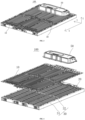
FIG. 3 is an assembly diagram of a battery according to some embodiments of the present application; -
FIG. 4 is an exploded schematic diagram of the battery shown inFIG. 3 ; -
FIG. 5 is a section view of the battery shown inFIG. 3 ; -
FIG. 6 is an exploded schematic diagram of the top cover of the battery shown inFIG. 3 ; and -
FIG. 7 is a section view of the top cover shown inFIG. 6 . - 1000, vehicle; 100, battery; 200, controller; 300, motor; 10, top cover; 11, heat exchange flow channel; 12, first heat exchange component; 13, second heat exchange component; 131, first heat exchange sub-component; 132, second heat exchange sub-component; 20, battery cell; 21, end cover; 21a, electrode terminal; 22, shell; 23, battery cell assembly; 23a, tab; 30, frame; 31, frame body; 32, support beam; 40, bottom cover; 50, power distribution box; X, length direction; Y, width direction; Z, thickness direction.
- In order to make the aforementioned objectives, features and advantages of the present application more obvious and easy to understand, the specific implementations of the present application are described in detail below with reference to the attached drawings. In the following description, numerous specific details are set forth in order to provide a thorough understanding of the present application. However, the present application can be implemented in many other ways different from those described herein, and those skilled in the art can make similar improvements without violating the connotation of the present application. Therefore, the present application is not limited to the specific embodiments disclosed below.
- In the description of the present application, it should be understood that the orientation or positional relationships indicated by the terms "central", "longitudinal", "transverse", "length", "width", "thickness", "upper", "lower", "front", "rear", "left", "right", "vertical", "horizontal", "top", "bottom", "inner", "outer", "clockwise", "anticlockwise", "axial", "radial", "circumferential", etc. are based on the orientation or positional relationships shown in the drawings and are only for facilitating the description of the present application and simplifying the description, rather than indicating or implying that the apparatus or element referred to must have a particular orientation or be constructed and operated in a particular orientation, and therefore will not be interpreted as limiting the present application.
- In addition, the terms "first" and "second" are used for descriptive purposes only, and cannot be construed as indicating or implying relative importance or implicitly indicating the number of technical features indicated. Therefore, a feature defined by "first" or "second" may expressly or implicitly include at least one of the features. In the description of the present application, the meaning of "a plurality of" is at least two, for example two or three, unless otherwise explicitly and specifically defined.
- In the present application, unless otherwise expressly specified and limited, the terms "mount", "link", "connect" and "fix" should be broadly understood, for example, they may be a fixed connection or a detachable connection or be integrated; or may be a mechanical connection or an electrical connection; or may be a direct connection or an indirect connection through an intermediate medium, or may be a communication between the interior of two elements or the interaction of two elements, unless otherwise specifically defined. For those of ordinary skill in the art, the specific meanings of the above terms in the present application can be understood according to specific situations.
- In the present application, unless otherwise explicitly specified and defined, the expression a first feature being "on" or "under" a second feature may be the case that the first feature is in direct contact with the second feature, or the first feature is in indirect contact with the second feature via an intermediate medium. Furthermore, the expression the first feature being "over", "above" and "on top of" the second feature may be a case that the first feature is directly above or obliquely above the second feature, or only means that the level of the first feature is higher than that of the second feature. The expression the first feature being "below", "underneath" or "under" the second feature may be a case that the first feature is directly underneath or obliquely underneath the second feature, or only means that the level of the first feature is lower than that of the second feature.
- It should be noted that when an element is referred to as "fixed to" or "arranged to" another element, it may be directly on the other element or there may be an intermediate element. When one element is considered to be "connected" to another element, it may be directly connected to another element or there may also be an intermediate element. The terms "vertical", "horizontal", "top", "bottom", "left", "right" and similar expressions used herein are for illustrative purposes only, and do not indicate that they are the only means of implementation.
- At present, from the perspective of the development of the market situation, power batteries are increasingly more widely used. Power batteries are not only applied in energy storage power source systems such as water, fire, wind and solar power stations, but also widely applied in electric transport tools, such as electric bicycles, electric motorcycles, and electric vehicles, as well as many fields, such as military equipment and aerospace. As the application fields of the power batteries continue to expand, their market demand is also constantly expanding.
- The applicant noticed that the traditional top cover only plays the role of protecting the battery cell and has a single function.
- In order to solve the problem of the single function of the traditional top cover, the applicant has found through research that the function of the top cover can be optimized, so that, for example, the top cover can not only protect the battery cells, but also cool or heat the battery cells.
- Based on the above considerations, in order to solve the problem of the single function of the top cover, the applicant has designed a battery after in-depth research. The battery comprises a cell, a top cover and a power distribution box. The top cover is sandwiched between the battery cell and the power distribution box. The power distribution box is used to control the voltage of the battery. A heat exchange flow channel is formed in the top cover, and the heat exchange flow channel is used to accommodate a fluid for regulating the temperature of the battery cell and the power distribution box.
- Since a heat exchange flow channel is formed in the top cover, and the heat exchange flow channel can accommodate the fluid for regulating the temperature of the battery cell and the temperature of the power distribution box. Therefore, the top cover not only has the function of protecting the battery cells, but also has the function of cooling or heating the battery cells and the power distribution box. At the same time, compared with traditional batteries, the power distribution box is located outside the battery box, which prevents the exhaust of the battery cells from damaging the components in the power distribution box.
- The battery disclosed in the embodiment of the present application can be used in, but not limited to, electrical apparatus such as vehicles, vessels, or aircrafts. The power supply system of an electrical apparatus device can comprise the battery disclosed in the present application, so that the battery cell can be well protected and the heat management of the battery cell can be carried out.
- An embodiment of the present application provides an electrical apparatus using a battery as a power source. The electrical apparatus may be, but is not limited to, a mobile phone, a tablet, a laptop, an electric toy, an electric tool, a battery cart, an electric vehicle, a ship, a spacecraft, and the like. Among them, the electric toy may include a stationary or mobile electric toy, for example, a game console, an electric car toy, an electric ship toy, and an electric aircraft toy, and the like, and the spacecraft may include an aircraft, a rocket, a space shuttle and a spaceship, and the like.
- For the convenience of description in the following embodiments, referring to
FIG. 1 , an electrical apparatus being avehicle 1000 according to an embodiment of the present application is taken as an example for the description. - The
vehicle 1000 may be a fuel vehicle, a gas vehicle or a new energy vehicle. The new energy vehicle may be an all-electric vehicle, a hybrid vehicle, an extended range electric vehicle, or the like. Abattery 100 is arranged in thevehicle 1000. Thebattery 100 may be arranged at the bottom or head or tail of thevehicle 1000. Thebattery 100 may be used as a power supply for thevehicle 1000, for example, thebattery 100 may be used as an operating power source for thevehicle 1000. Thevehicle 1000 may further include acontroller 200 and amotor 300. Thecontroller 200 is configured to control thebattery 100 to supply power to themotor 300, for example, to supply power for starting, navigation and driving of thevehicle 1000. - In some embodiments of the present application, the
battery 100 may not only be used as the operating power source for thevehicle 1000, but also as a driving power source for thevehicle 1000, to replace or partially replace fuel or natural gas to provide driving power for thevehicle 1000. - The
battery 100 includes a box andbattery cells 20, thebattery cells 20 are accommodated within the box. The box may include a first portion and a second portion that cover each other, and the first portion and the second portion jointly define an accommodating space for accommodating thebattery cell 20. The second portion may be a hollow structure with one end open, and the first portion may be a plate-like structure. In this case, the first portion constitutes thetop cover 10 of thebattery 100. - In the
battery 100, there may be a plurality ofbattery cells 20, and the plurality ofbattery cells 20 can be connected in series or in parallel or in parallel-series connection, where the parallel-series connection means that the plurality ofbattery cells 20 are connected in both series and parallel. The plurality ofbattery cells 20 can be directly connected together in series or in parallel or in parallel-series connection, and then the whole composed of the plurality ofbattery cells 20 can be accommodated in the box; and of course, thebattery 100 may also be in the form of abattery 100 module first formed by the plurality ofbattery cells 20 being connected in series or in parallel or in parallel-series connection, then a plurality ofbattery 100 modules can be connected in series or in parallel or in parallel-series connection to form a whole, and accommodated in the box. Thebattery 100 may further comprise other structures, for example, thebattery 100 may further include a bus component for realizing electrical connections between the plurality ofbattery cells 20. - Each
battery cell 20 may be asecondary battery 100 or aprimary battery 100; or it may be a lithium-sulfur battery 100, a sodium-ion battery 100 or a magnesium-ion battery 100, but is not limited thereto. Thebattery cells 20 may be cylindrical, flat, rectangular, or in other shapes. - The
battery cell 20 is the smallest unit constituting thebattery 100. Referring toFIG. 2 , thebattery cell 20 includes anend cover 21, ashell 22, abattery cell assembly 23 and other functional components. - The
end cover 21 is a component that covers an opening of theshell 22 to isolate the internal environment of thebattery cell 20 from the external environment. Without limitation, the shape of theend cover 21 may be adaptive to the shape of theshell 22 so as to be matched with theshell 22. Optionally, theend cover 21 may be made of a material (such as an aluminum alloy) with a certain hardness and strength, so that theend cover 21 is not easy to be deformed when being pressed and collided, thebattery cell 20 can have a higher structural strength, and the safety performance can also be improved. Functional components such aselectrode terminals 21a may be arranged on theend cover 21. Theelectrode terminals 21a can be used for being electrically connected to thebattery cell assembly 23 for outputting or inputting electric energy of thebattery cell 20. In some embodiments, theend cover 21 may be further provided with a pressure relief mechanism used for relieving internal pressure when the internal pressure or temperature of thebattery cell 20 reaches a threshold. Theend cover 21 may be made of various materials, such as copper, iron, aluminum, stainless steel, an aluminum alloy and plastic, which is not particularly limited in this embodiment of the present application. In some embodiments, an insulating member may be further arranged on an inner side of theend cover 21 and may be used for isolating an electrical connection component in theshell 22 from theend cover 21, thereby reducing the risk of short circuit. Exemplarily, the insulating member may be made of plastic, rubber, etc. - The
shell 22 is an assembly used to be matched with theend cover 21 to form the internal environment of thebattery cell 20, where the formed internal environment can be used to accommodate thebattery cell assembly 23, an electrolyte and other components. Theshell 22 and theend cover 21 may be separate components, the opening may be formed in theshell 22, and at the opening, the opening is covered with theend cover 21 so as to form the internal environment of thebattery cell 20. Without limitation, theend cover 21 and theshell 22 may also be integrated. Specifically, theend cover 21 and theshell 22 may form a common connection surface before other components enter the shell. When an interior of theshell 22 is required to be encapsulated, theshell 22 is covered with theend cover 21. Theshell 22 may be in various shapes and sizes, such as a rectangular solid, a cylinder and a hexagonal prism. Specifically, the shape of theshell 22 may be determined according to the specific shape and size of thebattery cell assembly 23. Theshell 22 may be made of various materials, such as copper, iron, aluminum, stainless steel, an aluminum alloy and plastic, which is not particularly limited in this embodiment of the present application. - The
battery cell assembly 23 is a component in which an electrochemical reaction occurs in thebattery cell 20. One or morebattery cell assemblies 23 may be contained within theshell 22. Thebattery cell assembly 23 is mainly formed by winding or stacking a positive electrode plate and a negative electrode plate, and a separator is usually arranged between the positive electrode plate and the negative electrode plate. The portions, with active materials, of the positive electrode plate and the negative electrode plate constitute a main body part of thebattery cell assembly 23, and the portions, without the active materials, of the positive electrode plate and the negative electrode plate respectively constitutetabs 23a. The positive tab and the negative tab may be located at one end of the main body part together or located at two ends of the main body part respectively. During charging and discharging of thebattery 100, the positive electrode active material and the negative electrode active material react with the electrolyte solution, and thetabs 23a are connected to theelectrode terminals 21a to form a current loop. - Referring to
FIGS. 3 to 5 , the present application provides abattery 100. Thebattery 100 includes abattery cell 20, atop cover 10 and apower distribution box 50. Thetop cover 10 is sandwiched between thebattery cell 20 and thepower distribution box 50. Thepower distribution box 50 is used to control thebattery 100. Specifically, thepower distribution box 50 is used to control the voltage and/or current of thebattery 100. Referring toFIGS. 6 and7 , a heatexchange flow channel 11 is formed in thetop cover 10, and the heatexchange flow channel 11 is used to accommodate a fluid to regulate the temperature of thebattery cell 20 and thepower distribution box 50. - "The
top cover 10 is sandwiched between thebattery cell 20 and thepower distribution box 50 " means that thepower distribution box 50, thetop cover 10 and thebattery cell 20 are stacked, and thetop cover 10 is an interlayer between thepower distribution box 50 and thebattery cell 20 to form a sandwich structure. Specifically, in the height direction of thebattery 100, thepower distribution box 50, thetop cover 10 and thebattery cell 20 are stacked. - The heat
exchange flow channel 11 is a passage that can accommodate a fluid for regulating the temperature of thebattery cell 20 and the high-voltage box. In the process of cooling or heating thebattery cell 20 and thepower distribution box 50, the fluid can circulate in the heatexchange flow channel 11 to transfer or take away heat. The cross-section of the flow channel can be of various shapes, such as a cuboid, a cylinder, and a hexagonal prism. - Fluids can be either liquids or gases. When the
top cover 10 is used to cool thebattery cells 20 and thepower distribution box 50, the liquid is also called a cooling medium. When thetop cover 10 is used to heat thebattery cells 20 and thepower distribution box 50, the liquid is also called a heating medium. - In the
above battery 100, since a heatexchange flow channel 11 is formed in thetop cover 10, and the heatexchange flow channel 11 can accommodate a fluid for regulating the temperature of thebattery cell 20 and the temperature of thepower distribution box 50. Therefore, thetop cover 10 not only has the function of protecting thebattery cells 20, but also has the function of cooling or heating thebattery cells 20 and thepower distribution box 50. At the same time, compared withtraditional batteries 100, thepower distribution box 50 is located outside the box of thebattery 100, which effectively improves the space utilization of thebattery 100. - Generally, the voltage of the
battery 100 is relatively high. If electrical apparatuses and electrical appliances such as themotor controller 200, the air conditioning system and the charging system are directly connected to thebattery 100, the wiring harness of thebattery 100 will be messy. Therefore, thebattery 100 needs to add a high-voltagepower distribution box 50 to distribute the high voltage to thebattery 100. Thepower distribution box 50 adopts a centralized power distribution solution with a compact structure design, convenient wiring layout, and quick and easy maintenance. According to the system architecture requirements of different customers, thepower distribution box 50 also needs to integrate some of thebattery 100 management system intelligent control management units, so as to further simplify the complexity of power distribution of the entire electrical apparatus. - According to some embodiments of the present application, optionally, the
power distribution box 50 is provided with one or more of a fuse, a relay, a current sensor and a BMS battery system inside to facilitate control of thebattery 100. The fuse is a kind of electrical appliance that when a current flowing through the fuse exceeds a specified value, the fuse-element fuses with heat generated by itself, thereby disconnecting a circuit. The relay is an electrical control device, which is an electrical appliance that, when the change of input quantity (excitation quantity) reaches the specified requirement, causes a predetermined step change in the controlled quantity in the electrical output circuit. The current sensor is a detection apparatus that can sense the information of the measured current, convert the detected and sensed information into electrical signals or information in other desired forms conforming to certain standards and requirements according to a certain rule and output them, to meet the requirements for transmitting, processing, storing, displaying, recording, and controlling the information. The BMS battery system is commonly called battery nanny or battery housekeeper, mainly used to intelligently manage and maintain the battery units, prevent overcharging and over-discharging of batteries, extend the battery life, and monitor the battery state. - According to some embodiments of the present application, optionally, the
power distribution box 50 is a sealed structure. In this way, liquid can be prevented from entering thepower distribution box 50 and damaging the components in thepower distribution box 50. - According to some embodiments of the present application, optionally, referring to
FIG. 6 andFIG. 7 , thetop cover 10 includes a firstheat exchange component 12 and a secondheat exchange component 13, and the firstheat exchange component 12 and the secondheat exchange component 13 are connected to form a heatexchange flow channel 11. - The first
heat exchange component 12 and the secondheat exchange component 13 are both components that can exchange heat with external components, that is, the heat of the fluid can be transferred to the firstheat exchange component 12 and the secondheat exchange component 13, and the firstheat exchange component 12 and the secondheat exchange component 13 conduct the heat of the fluid to external components, such as thebattery cell 20 and the components of thepower distribution box 50. Generally, the firstheat exchange component 12 and the secondheat exchange component 13 are both made of metal. - In the above arrangement, the first
heat exchange component 12 and the secondheat exchange component 13 are connected to form the heatexchange flow channel 11, which facilitates the formation of the heatexchange flow channel 11. - It is conceivable that in other embodiments, the heat
exchange flow channel 11 may also be formed in other ways, which is not limited here. - According to some embodiments of the present application, optionally, the second
heat exchange component 13 is recessed away from the firstheat exchange component 12 to form the heatexchange flow channel 11, so as to facilitate the formation of the heatexchange flow channel 11. - It is conceivable that in other embodiments, the specific formation method of the heat
exchange flow channel 11 is not limited. - According to some embodiments of the present application, optionally, the first
heat exchange component 12 is a flat plate, referring toFIG. 7 , the secondheat exchange component 13 includes a firstheat exchange sub-component 131 and a secondheat exchange sub-component 132 that are connected to each other, and the firstheat exchange sub-component 131 is recessed relative to the secondheat exchange sub-component 132 in the direction away from the firstheat exchange component 12; a heatexchange flow channel 11 is formed between the firstheat exchange sub-component 131 and the firstheat exchange component 12, and the secondheat exchange sub-component 132 is in contact with the firstheat exchange component 12. Thebattery cell 20 abuts a side of the firstheat exchange component 12 that is away from the secondheat exchange component 13. - The first
heat exchange component 12 is a flat plate. The firstheat exchange sub-component 131 is recessed relative to the secondheat exchange sub-component 132 in the direction away from the firstheat exchange component 12, which means that the secondheat exchange component 13 is a concave-convex plate with a concave-convex arrangement, that is, the secondheat exchange component 13 is a mold cavity plate with a mold cavity, and the wall of the mold cavity and the firstheat exchange component 12 define the heatexchange flow channel 11. - In the above arrangement, the first
heat exchange component 12 is a flat plate, so as to facilitate connection with thebattery cell 20. For example, the bottom or side wall (other than the terminal post surface) of thebattery cell 20 is adhered to the plane of the firstheat exchange component 12 away from the firstheat exchange component 12. At the same time, since the secondheat exchange component 13 includes a firstheat exchange sub-component 131 and a secondheat exchange sub-component 132 which are connected to each other, and the firstheat exchange sub-component 131 is recessed relative to the secondheat exchange sub-component 132 in the direction away from the firstheat exchange component 12, that is, the secondheat exchange component 13 has a concave-convex structure, thetop cover 10 has great impact resistance and provides good protection for thebattery cells 20. - Further, the heat
exchange flow channel 11 comprises a plurality of sub-flow channels communicating with each other. The secondheat exchange component 13 comprises a plurality of firstheat exchange sub-components 131 and a plurality of secondheat exchange sub-components 132, and one of the sub-flow channel is formed between each of the firstheat exchange sub-components 131 and the firstheat exchange component 12. - In the above arrangement, since the heat
exchange flow channel 11 comprises a plurality of sub-flow channels, the fluid flows in the plurality of sub-flow channels to regulate the temperature uniformity of thebattery cells 20 and the components of thepower distribution box 50. At the same time, since the heatexchange flow channel 11 comprises a plurality of sub-flow channels, and correspondingly, the secondheat exchange component 13 comprises a plurality of firstheat exchange sub-components 131 and a plurality of secondheat exchange sub-components 132, the number of concave-convex structures of the secondheat exchange component 13 is increased and the impact resistance of thetop cover 10 is further improved. - According to some embodiments of the present application, optionally, the thickness of both the first
heat exchange component 12 and the secondheat exchange component 13 is 0.6 millimeters (mm) to 3 millimeters (mm). - The thickness direction Z of the
top cover 10 is the direction in which the firstheat exchange component 12 and the secondheat exchange component 13 cover each other, and the length direction X, width direction Y and thickness direction Z (seeFIG. 3 ) of thetop cover 10 are perpendicular to each other. The thickness of the firstheat exchange component 12 is its dimension in the thickness direction Z of thetop cover 10, and the thickness of the secondheat exchange component 13 is its dimension in the thickness direction Z of thetop cover 10. - The thickness of the first
heat exchange component 12 and the secondheat exchange component 13 is set to 0.6 mm to 3 mm, which has a good heat exchange effect while ensuring the strength of both. - It should be understood that, in other embodiments, the thickness of the first
heat exchange component 12 and the secondheat exchange component 13 is not limited and can be selected as needed. Meanwhile, the dimensions of the firstheat exchange component 12 and the secondheat exchange component 13 in the length direction X and the width direction Y of thetop cover 10 are not limited. - According to some embodiments of the present application, optionally, in the thickness direction Z of the
top cover 10, the depth of the heatexchange flow channel 11 is 1 to 3 times the thickness of the firstheat exchange component 12; and/or the depth of the heatexchange flow channel 11 is 2 mm to 7 mm. - In the above arrangement, the depth of the heat
exchange flow channel 11 ensures that the amount of fluid accommodated is appropriate, so that the amount of fluid accommodated is not too small, thereby ensuring the heat exchange effect, while avoiding accommodating too much fluid and thus affecting the strength of thetop cover 10. - It should be understood that in other embodiments, the depth of the heat
exchange flow channel 11 is not limited. - According to some embodiments of the present application, optionally, the first
heat exchange component 12 and the secondheat exchange component 13 are fixed by welding or bonding, thus ensuring the fixing effect of the firstheat exchange component 12 and the secondheat exchange component 13. - It is conceivable that in other embodiments, the first
heat exchange component 12 and the secondheat exchange component 13 may also be connected and fixed by screws, which is not limited here. - According to some embodiments of the present application, optionally, the material selected for the first
heat exchange component 12 is steel or aluminum; and/or the material selected for the secondheat exchange component 13 is steel or aluminum. In this way, the heat exchange effect between the firstheat exchange component 12 and the secondheat exchange component 13 is guaranteed. - Of course, in other embodiments, there is no limitation on the material of the first
heat exchange component 12 and the secondheat exchange component 13, as long as the heat exchange effect of the firstheat exchange component 12 and the secondheat exchange component 13 is guaranteed. - According to some embodiments of the present application, optionally, referring to
FIGS. 3 to 5 , thebattery 100 also includes aframe 30 and abottom cover 40, and the two ends of theframe 30 form a top opening and a bottom opening respectively. Thetop cover 10 is installed on the top of theframe 30 to seal the top opening, and thebottom cover 40 is installed on the bottom of theframe 30 to seal the bottom opening. Thetop cover 10, theframe 30 and thebottom cover 40 define an accommodating space. Thebattery cell 20 is accommodated in the accommodating space. - The
frame 30 and thebottom cover 40 are both part of the second portion of the box. Theframe 30 has a structure with a hollow interior and openings at both ends. The accommodating space is a closed space with a certain volume for accommodating thebattery cell 20. - It should be noted that in the thickness direction Z of the
top cover 10, that is, the height direction of thebattery 100, the top opening and the bottom opening are respectively located at two ends of theframe 30. - In the above arrangement, the
top cover 10 and thebottom cover 40 are respectively mounted on the top and bottom of theframe 30, so that the height of the entire box of thebattery 100 is relatively low, reducing the space occupied by thebattery 100 in the height direction. - According to some embodiments of the present application, optionally, the
frame 30 has a hollow cuboid structure, that is, theframe 30 includes a first side portion, a second side portion, a third side portion, and a fourth side portion which are sequentially connected end to end. This facilitates the manufacture of theframe 30. It should be understood that in other embodiments, the shape of theframe 30 can be set as needed, such as theframe 30 can also be a hollow cylindrical structure. - According to some embodiments of the present application, optionally, the
frame 30 includes a frame body 31 and asupport beam 32, thesupport beam 32 is connected to the frame body 31, the frame body 31 and thesupport beam 32 together form a top opening, and thesupport beam 32 is arranged below and supports the top cover. - The frame body 31 is the main structure of the
frame 30 , and thesupport beam 32 is the reinforcement structure of theframe 30. Thesupport beam 32 includes a transverse beam and/or a longitudinal beam. In a specific implementation, thesupport beam 32 only includes a transverse beam. In another specific implementation, thesupport beam 32 only includes a longitudinal beam. In yet another specific implementation, thesupport beam 32 includes both a transverse beam and a longitudinal beam. - The transverse beam is a beam extending along the width direction Y, and the longitudinal beam is a beam extending along the length direction X.
- In the above arrangement, since the
support beam 32 is arranged below and supports the top cover, it has a good supporting effect on thetop cover 10. - According to some embodiments of the present application, the present application further provides an electrical apparatus comprising the
battery 100 described in any one of the above solutions, thebattery 100 being used to provide electric energy to the electrical apparatus. - According to some embodiments of the present application, optionally, the electrical apparatus is a
vehicle 1000, thetop cover 10 is a floor of thevehicle 1000, and the side of the secondheat exchange component 13 away from the firstheat exchange component 12 is arranged to face the passenger compartment. - The floor is a footrest in the passenger compartment of the
vehicle 1000 for passengers to step on. The side of the secondheat exchange component 13 away from the firstheat exchange component 12 is arranged to face the passenger compartment of thevehicle 1000. - In this way, the
top cover 10 can not only realize the function of heat exchange with thebattery cells 20, but also heat or cool the passenger compartment to improve the user experience. Since thetop cover 10 serves as the floor of thevehicle 1000, the utilization rate of the entire vehicle height is greatly improved, and abattery 100 pack with better energy can be obtained. There is a heatexchange flow channel 11 in thetop cover 10. As the floor of thevehicle 1000, the top cover can better isolate the noise generated by the vehicle underbody. - According to some embodiments of the present application, optionally, the
power distribution box 50 is located directly below or behind the rear seats of thevehicle 1000. - Placing the
power distribution box 50 below or behind the rear seat of thevehicle 1000 can greatly utilize the space of the entire vehicle. - It is conceivable that in other embodiments, the
power distribution box 50 may also be disposed at other suitable locations, which is not limited here. - Referring to
FIGS. 3 to 5 , the present application provides abattery 100. Thebattery 100 includes abattery cell 20, atop cover 10 and apower distribution box 50. Thetop cover 10 is sandwiched between thebattery cell 20 and thepower distribution box 50. Thepower distribution box 50 is used to control thebattery 100. Referring toFIGS. 6 and7 , a heatexchange flow channel 11 is formed in thetop cover 10, and the heatexchange flow channel 11 is used to accommodate a fluid to regulate the temperature of thebattery cell 20 and thepower distribution box 50. - The
battery 100 also includes aframe 30 and abottom cover 40, and the two ends of theframe 30 form a top opening and a bottom opening respectively. Thetop cover 10 is installed on the top of theframe 30 to seal the top opening, and thebottom cover 40 is installed on the bottom of theframe 30 to seal the bottom opening. Thetop cover 10, theframe 30 and thebottom cover 40 define an accommodating space. Thebattery cell 20 is accommodated in the accommodating space. - The technical features of the above-mentioned embodiments can be combined arbitrarily. In order to make the description concise, not all possible combinations of the technical features in the above embodiments are described. However, all the combinations of the technical features should be considered as falling within the scope described in the specification provided that they do not conflict with each other.
- The above embodiments only describe several implementations of the present application, and the description thereof is specific and detailed, but cannot therefore be understood as a limitation on the patent scope of the present application. It should be noted that those of ordinary skill in the art may further make variations and improvements without departing from the concept of the present application, all of which fall within the scope of protection of the present application. Therefore, the scope of protection of the present patent application shall be subject to the appended claims.
Claims (16)
- A battery comprising a battery cell (20), a top cover (10) and a power distribution box (50), wherein the top cover (10) is sandwiched between the battery cell (20) and the power distribution box (50), and the power distribution box (50) is used to control the battery;
a heat exchange flow channel (11) is formed in the top cover (10), and the heat exchange flow channel (11) is used to accommodate a fluid to regulate the temperature of the battery cell (20) and the power distribution box (50). - The battery according to claim 1, wherein the power distribution box (50) is provided with one or more of a fuse, a relay, a current sensor and a BMS battery system inside.
- The battery according to claim 1, wherein the power distribution box (50) is a sealed structure.
- The battery according to claim 1, wherein the top cover (10) comprises a first heat exchange component (12) and a second heat exchange component (13), and the first heat exchange component (12) and the second heat exchange component (13) are connected to form the heat exchange flow channel (11).
- The battery according to claim 4, wherein the second heat exchange component (13) is recessed away from the first heat exchange component (12) to form the heat exchange flow channel (11).
- The battery according to claim 5, wherein the first heat exchange component (12) is a flat plate, the second heat exchange component (13) comprises a first heat exchange sub-component (131) and a second heat exchange sub-component (132) connected to each other, the first heat exchange sub-component (131) is recessed relative to the second heat exchange sub-component (132) in a direction away from the first heat exchange component (12); the heat exchange flow channel (11) is formed between the first heat exchange sub-component (131) and the first heat exchange component (12), and the second heat exchange sub-component (132) is in contact with the first heat exchange component (12);
the battery cell (20) is connected to a side of the first heat exchange component (12) away from the second heat exchange component (13). - The battery according to claim 6, wherein the heat exchange flow channel (11) comprises a plurality of sub-flow channels communicating with each other;
the second heat exchange component (13) comprises a plurality of first heat exchange sub-components (131) and a plurality of second heat exchange sub-components (132), and one of the sub-flow channels is formed between each of the first heat exchange sub-components (131) and the first heat exchange component (12). - The battery according to claim 4, wherein the thickness of both the first heat exchange component (12) and the second heat exchange component (13) is 0.6 mm to 3 mm.
- The battery according to any one of claims 4 to 8, wherein in a thickness direction (Z) of the top cover (10), a depth of the heat exchange flow channel (11) is 1 to 3 times the thickness of the first heat exchange component (12); and/or
the depth of the heat exchange flow channel (11) is 2 mm to 7 mm. - The battery according to claim 4, wherein the first heat exchange component (12) and the second heat exchange component (13) are fixed by welding or bonding.
- The battery according to claim 4, wherein the material selected for the first heat exchange component (12) is steel or aluminum; and/or the material selected for the second heat exchange component (13) is steel or aluminum.
- The battery according to claim 1, wherein the battery further comprises a frame (30) and a bottom cover (40), the two ends of the frame (30) respectively form a top opening and a bottom opening, the top cover (10) is mounted on the top of the frame (30) to seal the top opening, the bottom cover (40) is mounted on the bottom of the frame (30) to seal the bottom opening, and the top cover (10), the frame (30) and the bottom cover (40) define an accommodating space;
the battery cell (20) is accommodated in the accommodating space. - The battery according to claim 12, wherein the frame (30) comprises a frame body (31) and a support beam (32), the support beam (32) is connected to the frame body (31), the frame body (31) and the support beam (32) together form the top opening, and the support beam (32) is arranged below and supports the top cover (10).
- An electrical apparatus, comprising the battery according to any one of claims 1 to 13.
- The electrical apparatus according to claim 14, wherein the electrical apparatus is a vehicle (1000), the top cover (10) is a floor of the vehicle (1000), and a side of the second heat exchange component (13) away from the first heat exchange component (12) is arranged to face the passenger compartment of the vehicle (1000).
- The electrical apparatus according to claim 14, wherein the power distribution box (50) is located directly below or behind a rear seat of the vehicle (1000).
Applications Claiming Priority (1)
| Application Number | Priority Date | Filing Date | Title |
|---|---|---|---|
| PCT/CN2022/113962 WO2024040392A1 (en) | 2022-08-22 | 2022-08-22 | Battery and electric device |
Publications (2)
| Publication Number | Publication Date |
|---|---|
| EP4560784A1 true EP4560784A1 (en) | 2025-05-28 |
| EP4560784A4 EP4560784A4 (en) | 2025-07-30 |
Family
ID=86798226
Family Applications (1)
| Application Number | Title | Priority Date | Filing Date |
|---|---|---|---|
| EP22955942.2A Pending EP4560784A4 (en) | 2022-08-22 | 2022-08-22 | BATTERY AND ELECTRICAL DEVICE |
Country Status (4)
| Country | Link |
|---|---|
| US (1) | US20250192276A1 (en) |
| EP (1) | EP4560784A4 (en) |
| CN (2) | CN116325325A (en) |
| WO (1) | WO2024040392A1 (en) |
Families Citing this family (8)
| Publication number | Priority date | Publication date | Assignee | Title |
|---|---|---|---|---|
| EP4560784A4 (en) * | 2022-08-22 | 2025-07-30 | Contemporary Amperex Technology Co Ltd | BATTERY AND ELECTRICAL DEVICE |
| CN220904674U (en) * | 2023-09-27 | 2024-05-07 | 比亚迪股份有限公司 | High-voltage system and electric vehicle |
| CN121039876A (en) * | 2023-12-22 | 2025-11-28 | 宁德时代新能源科技股份有限公司 | Batteries and electrical devices |
| CN222637491U (en) * | 2024-03-05 | 2025-03-18 | 宁德时代新能源科技股份有限公司 | Batteries and electrical devices |
| CN120613531A (en) * | 2024-03-06 | 2025-09-09 | 宁德时代新能源科技股份有限公司 | Batteries and vehicles |
| CN120613511A (en) * | 2024-03-06 | 2025-09-09 | 宁德时代新能源科技股份有限公司 | Box, battery and electrical device |
| CN221201428U (en) * | 2024-04-02 | 2024-06-21 | 宁德时代新能源科技股份有限公司 | Battery and electricity utilization device |
| CN119560687A (en) * | 2025-01-22 | 2025-03-04 | 宁德时代新能源科技股份有限公司 | Battery device and electric equipment |
Family Cites Families (13)
| Publication number | Priority date | Publication date | Assignee | Title |
|---|---|---|---|---|
| US9923251B2 (en) * | 2016-02-10 | 2018-03-20 | Atieva, Inc. | EV battery pack cooling system |
| CN207565708U (en) * | 2017-12-11 | 2018-07-03 | 北京新能源汽车股份有限公司 | Floor and electric automobile |
| US12230820B2 (en) * | 2019-01-09 | 2025-02-18 | Byd Company Limited | Power battery pack and electric vehicle |
| CN210984802U (en) * | 2019-11-29 | 2020-07-10 | 比亚迪股份有限公司 | Battery pack structure and vehicle |
| CN111987261A (en) * | 2020-08-31 | 2020-11-24 | 重庆金康赛力斯新能源汽车设计院有限公司 | Upper cover of integrated power battery |
| CN114930614B (en) * | 2020-11-07 | 2024-03-22 | 宁德时代新能源科技股份有限公司 | Electric device, method for preparing electric device and device for preparing electric device |
| CN216054919U (en) * | 2021-08-31 | 2022-03-15 | 宁德时代新能源科技股份有限公司 | Battery box, battery and power consumption device |
| CN216120489U (en) * | 2021-10-11 | 2022-03-22 | 宁德时代新能源科技股份有限公司 | Battery shell, battery monomer, battery and power consumption device |
| CN216389574U (en) * | 2021-11-26 | 2022-04-26 | 宁德时代新能源科技股份有限公司 | Battery box, battery and power utilization device |
| CN216720173U (en) * | 2022-01-18 | 2022-06-10 | 宁德时代新能源科技股份有限公司 | Battery box, battery and power consumption device |
| CN114571976B (en) * | 2022-02-21 | 2023-05-05 | 江苏大学 | Integrated structure of automobile body and battery package under integrated electric automobile |
| CN114435104A (en) * | 2022-03-10 | 2022-05-06 | 威睿电动汽车技术(宁波)有限公司 | Vehicle chassis subassembly and car |
| EP4560784A4 (en) * | 2022-08-22 | 2025-07-30 | Contemporary Amperex Technology Co Ltd | BATTERY AND ELECTRICAL DEVICE |
-
2022
- 2022-08-22 EP EP22955942.2A patent/EP4560784A4/en active Pending
- 2022-08-22 CN CN202280005973.7A patent/CN116325325A/en active Pending
- 2022-08-22 WO PCT/CN2022/113962 patent/WO2024040392A1/en not_active Ceased
- 2022-12-09 CN CN202223304423.1U patent/CN219419377U/en active Active
-
2025
- 2025-02-20 US US19/058,998 patent/US20250192276A1/en active Pending
Also Published As
| Publication number | Publication date |
|---|---|
| WO2024040392A1 (en) | 2024-02-29 |
| EP4560784A4 (en) | 2025-07-30 |
| US20250192276A1 (en) | 2025-06-12 |
| CN219419377U (en) | 2023-07-25 |
| CN116325325A (en) | 2023-06-23 |
Similar Documents
| Publication | Publication Date | Title |
|---|---|---|
| EP4560784A1 (en) | Battery and electric device | |
| EP4027433B1 (en) | Electrical device, method for preparing electrical device, and apparatus for preparing electrical device | |
| US20180248237A1 (en) | Battery pack | |
| US11929474B2 (en) | Battery module and battery pack thermal control system | |
| US20250192275A1 (en) | Battery top cover, battery, and electrical apparatus | |
| US20080274397A1 (en) | Mounting Structure of Electrical Equipment | |
| US12315965B2 (en) | Battery cell, battery and power consumption apparatus | |
| KR20240090382A (en) | Battery cell pack for electric vehicles | |
| EP4425654A1 (en) | Battery cell, battery and electric device | |
| CN220569795U (en) | Battery box, battery and electrical device | |
| EP4510306A1 (en) | Battery box, battery, and electric device | |
| US20230238642A1 (en) | Battery cell, battery, power consuming device, and method for manufacturing battery cell | |
| US20250096385A1 (en) | Battery compartment and battery swapping station | |
| KR102811252B1 (en) | Battery cell, battery, electrical device, manufacturing equipment and method for battery cell | |
| CN222126920U (en) | Batteries, battery modules, battery packs, energy storage devices and power consumption devices | |
| US12573694B2 (en) | Current collector assembly with an elongated fuse | |
| US20240297400A1 (en) | Battery assemblies, vehicles, and methods with gas manifold liners and battery tray seals for improved cell gas venting | |
| US20240097143A1 (en) | Battery unit, battery, and power consuming device | |
| CN219457774U (en) | Battery box, battery and electrical device | |
| CN223625137U (en) | Battery device and electricity utilization device | |
| CN220527085U (en) | Battery, energy storage system and electricity utilization device | |
| US20250379315A1 (en) | Modular battery packs | |
| US20250357640A1 (en) | Current collector assembly with curved interconnect portions | |
| CN216773449U (en) | Battery device and electric automobile | |
| US20250246718A1 (en) | Thermal management systems for managing both convective and conductive heat transfer within traction battery packs |
Legal Events
| Date | Code | Title | Description |
|---|---|---|---|
| STAA | Information on the status of an ep patent application or granted ep patent |
Free format text: STATUS: THE INTERNATIONAL PUBLICATION HAS BEEN MADE |
|
| PUAI | Public reference made under article 153(3) epc to a published international application that has entered the european phase |
Free format text: ORIGINAL CODE: 0009012 |
|
| STAA | Information on the status of an ep patent application or granted ep patent |
Free format text: STATUS: REQUEST FOR EXAMINATION WAS MADE |
|
| 17P | Request for examination filed |
Effective date: 20250219 |
|
| AK | Designated contracting states |
Kind code of ref document: A1 Designated state(s): AL AT BE BG CH CY CZ DE DK EE ES FI FR GB GR HR HU IE IS IT LI LT LU LV MC MK MT NL NO PL PT RO RS SE SI SK SM TR |
|
| A4 | Supplementary search report drawn up and despatched |
Effective date: 20250626 |
|
| RIC1 | Information provided on ipc code assigned before grant |
Ipc: H01M 10/613 20140101AFI20250620BHEP Ipc: H01M 10/615 20140101ALI20250620BHEP Ipc: H01M 10/625 20140101ALI20250620BHEP Ipc: H01M 10/6556 20140101ALI20250620BHEP Ipc: H01M 10/667 20140101ALI20250620BHEP Ipc: H01M 50/204 20210101ALI20250620BHEP Ipc: H01M 50/249 20210101ALI20250620BHEP Ipc: H01M 50/273 20210101ALI20250620BHEP Ipc: B60K 1/04 20190101ALI20250620BHEP Ipc: B60L 50/64 20190101ALI20250620BHEP |
|
| DAV | Request for validation of the european patent (deleted) | ||
| DAX | Request for extension of the european patent (deleted) |