EP4560782A2 - Battery cell, battery cell fabrication method, aviation battery, and method for monitoring aviation battery - Google Patents
Battery cell, battery cell fabrication method, aviation battery, and method for monitoring aviation battery Download PDFInfo
- Publication number
- EP4560782A2 EP4560782A2 EP24215154.6A EP24215154A EP4560782A2 EP 4560782 A2 EP4560782 A2 EP 4560782A2 EP 24215154 A EP24215154 A EP 24215154A EP 4560782 A2 EP4560782 A2 EP 4560782A2
- Authority
- EP
- European Patent Office
- Prior art keywords
- battery cell
- battery
- sensor strips
- electrode assembly
- aviation
- Prior art date
- Legal status (The legal status is an assumption and is not a legal conclusion. Google has not performed a legal analysis and makes no representation as to the accuracy of the status listed.)
- Pending
Links
Images




Classifications
-
- H—ELECTRICITY
- H01—ELECTRIC ELEMENTS
- H01M—PROCESSES OR MEANS, e.g. BATTERIES, FOR THE DIRECT CONVERSION OF CHEMICAL ENERGY INTO ELECTRICAL ENERGY
- H01M50/00—Constructional details or processes of manufacture of the non-active parts of electrochemical cells other than fuel cells, e.g. hybrid cells
- H01M50/50—Current conducting connections for cells or batteries
- H01M50/569—Constructional details of current conducting connections for detecting conditions inside cells or batteries, e.g. details of voltage sensing terminals
-
- H—ELECTRICITY
- H01—ELECTRIC ELEMENTS
- H01M—PROCESSES OR MEANS, e.g. BATTERIES, FOR THE DIRECT CONVERSION OF CHEMICAL ENERGY INTO ELECTRICAL ENERGY
- H01M10/00—Secondary cells; Manufacture thereof
- H01M10/42—Methods or arrangements for servicing or maintenance of secondary cells or secondary half-cells
- H01M10/48—Accumulators combined with arrangements for measuring, testing or indicating the condition of cells, e.g. the level or density of the electrolyte
-
- B—PERFORMING OPERATIONS; TRANSPORTING
- B64—AIRCRAFT; AVIATION; COSMONAUTICS
- B64D—EQUIPMENT FOR FITTING IN OR TO AIRCRAFT; FLIGHT SUITS; PARACHUTES; ARRANGEMENT OR MOUNTING OF POWER PLANTS OR PROPULSION TRANSMISSIONS IN AIRCRAFT
- B64D27/00—Arrangement or mounting of power plants in aircraft; Aircraft characterised by the type or position of power plants
- B64D27/02—Aircraft characterised by the type or position of power plants
- B64D27/30—Aircraft characterised by electric power plants
- B64D27/35—Arrangements for on-board electric energy production, distribution, recovery or storage
- B64D27/357—Arrangements for on-board electric energy production, distribution, recovery or storage using batteries
-
- G—PHYSICS
- G01—MEASURING; TESTING
- G01K—MEASURING TEMPERATURE; MEASURING QUANTITY OF HEAT; THERMALLY-SENSITIVE ELEMENTS NOT OTHERWISE PROVIDED FOR
- G01K11/00—Measuring temperature based upon physical or chemical changes not covered by groups G01K3/00, G01K5/00, G01K7/00 or G01K9/00
- G01K11/32—Measuring temperature based upon physical or chemical changes not covered by groups G01K3/00, G01K5/00, G01K7/00 or G01K9/00 using changes in transmittance, scattering or luminescence in optical fibres
- G01K11/3206—Measuring temperature based upon physical or chemical changes not covered by groups G01K3/00, G01K5/00, G01K7/00 or G01K9/00 using changes in transmittance, scattering or luminescence in optical fibres at discrete locations in the fibre, e.g. using Bragg scattering
-
- G—PHYSICS
- G01—MEASURING; TESTING
- G01L—MEASURING FORCE, STRESS, TORQUE, WORK, MECHANICAL POWER, MECHANICAL EFFICIENCY, OR FLUID PRESSURE
- G01L1/00—Measuring force or stress, in general
- G01L1/24—Measuring force or stress, in general by measuring variations of optical properties of material when it is stressed, e.g. by photoelastic stress analysis using infrared, visible light, ultraviolet
- G01L1/242—Measuring force or stress, in general by measuring variations of optical properties of material when it is stressed, e.g. by photoelastic stress analysis using infrared, visible light, ultraviolet the material being an optical fibre
- G01L1/246—Measuring force or stress, in general by measuring variations of optical properties of material when it is stressed, e.g. by photoelastic stress analysis using infrared, visible light, ultraviolet the material being an optical fibre using integrated gratings, e.g. Bragg gratings
-
- H—ELECTRICITY
- H01—ELECTRIC ELEMENTS
- H01M—PROCESSES OR MEANS, e.g. BATTERIES, FOR THE DIRECT CONVERSION OF CHEMICAL ENERGY INTO ELECTRICAL ENERGY
- H01M10/00—Secondary cells; Manufacture thereof
- H01M10/04—Construction or manufacture in general
-
- H—ELECTRICITY
- H01—ELECTRIC ELEMENTS
- H01M—PROCESSES OR MEANS, e.g. BATTERIES, FOR THE DIRECT CONVERSION OF CHEMICAL ENERGY INTO ELECTRICAL ENERGY
- H01M10/00—Secondary cells; Manufacture thereof
- H01M10/04—Construction or manufacture in general
- H01M10/0431—Cells with wound or folded electrodes
-
- H—ELECTRICITY
- H01—ELECTRIC ELEMENTS
- H01M—PROCESSES OR MEANS, e.g. BATTERIES, FOR THE DIRECT CONVERSION OF CHEMICAL ENERGY INTO ELECTRICAL ENERGY
- H01M10/00—Secondary cells; Manufacture thereof
- H01M10/04—Construction or manufacture in general
- H01M10/049—Processes for forming or storing electrodes in the battery container
-
- H—ELECTRICITY
- H01—ELECTRIC ELEMENTS
- H01M—PROCESSES OR MEANS, e.g. BATTERIES, FOR THE DIRECT CONVERSION OF CHEMICAL ENERGY INTO ELECTRICAL ENERGY
- H01M10/00—Secondary cells; Manufacture thereof
- H01M10/42—Methods or arrangements for servicing or maintenance of secondary cells or secondary half-cells
-
- H—ELECTRICITY
- H01—ELECTRIC ELEMENTS
- H01M—PROCESSES OR MEANS, e.g. BATTERIES, FOR THE DIRECT CONVERSION OF CHEMICAL ENERGY INTO ELECTRICAL ENERGY
- H01M10/00—Secondary cells; Manufacture thereof
- H01M10/42—Methods or arrangements for servicing or maintenance of secondary cells or secondary half-cells
- H01M10/48—Accumulators combined with arrangements for measuring, testing or indicating the condition of cells, e.g. the level or density of the electrolyte
- H01M10/486—Accumulators combined with arrangements for measuring, testing or indicating the condition of cells, e.g. the level or density of the electrolyte for measuring temperature
-
- H—ELECTRICITY
- H01—ELECTRIC ELEMENTS
- H01M—PROCESSES OR MEANS, e.g. BATTERIES, FOR THE DIRECT CONVERSION OF CHEMICAL ENERGY INTO ELECTRICAL ENERGY
- H01M50/00—Constructional details or processes of manufacture of the non-active parts of electrochemical cells other than fuel cells, e.g. hybrid cells
- H01M50/10—Primary casings; Jackets or wrappings
- H01M50/102—Primary casings; Jackets or wrappings characterised by their shape or physical structure
- H01M50/103—Primary casings; Jackets or wrappings characterised by their shape or physical structure prismatic or rectangular
-
- H—ELECTRICITY
- H01—ELECTRIC ELEMENTS
- H01M—PROCESSES OR MEANS, e.g. BATTERIES, FOR THE DIRECT CONVERSION OF CHEMICAL ENERGY INTO ELECTRICAL ENERGY
- H01M50/00—Constructional details or processes of manufacture of the non-active parts of electrochemical cells other than fuel cells, e.g. hybrid cells
- H01M50/10—Primary casings; Jackets or wrappings
- H01M50/102—Primary casings; Jackets or wrappings characterised by their shape or physical structure
- H01M50/105—Pouches or flexible bags
-
- H—ELECTRICITY
- H01—ELECTRIC ELEMENTS
- H01M—PROCESSES OR MEANS, e.g. BATTERIES, FOR THE DIRECT CONVERSION OF CHEMICAL ENERGY INTO ELECTRICAL ENERGY
- H01M50/00—Constructional details or processes of manufacture of the non-active parts of electrochemical cells other than fuel cells, e.g. hybrid cells
- H01M50/10—Primary casings; Jackets or wrappings
- H01M50/102—Primary casings; Jackets or wrappings characterised by their shape or physical structure
- H01M50/107—Primary casings; Jackets or wrappings characterised by their shape or physical structure having curved cross-section, e.g. round or elliptic
-
- H—ELECTRICITY
- H01—ELECTRIC ELEMENTS
- H01M—PROCESSES OR MEANS, e.g. BATTERIES, FOR THE DIRECT CONVERSION OF CHEMICAL ENERGY INTO ELECTRICAL ENERGY
- H01M50/00—Constructional details or processes of manufacture of the non-active parts of electrochemical cells other than fuel cells, e.g. hybrid cells
- H01M50/20—Mountings; Secondary casings or frames; Racks, modules or packs; Suspension devices; Shock absorbers; Transport or carrying devices; Holders
- H01M50/249—Mountings; Secondary casings or frames; Racks, modules or packs; Suspension devices; Shock absorbers; Transport or carrying devices; Holders specially adapted for aircraft or vehicles, e.g. cars or trains
-
- H—ELECTRICITY
- H01—ELECTRIC ELEMENTS
- H01M—PROCESSES OR MEANS, e.g. BATTERIES, FOR THE DIRECT CONVERSION OF CHEMICAL ENERGY INTO ELECTRICAL ENERGY
- H01M2220/00—Batteries for particular applications
- H01M2220/20—Batteries in motive systems, e.g. vehicle, ship, plane
-
- Y—GENERAL TAGGING OF NEW TECHNOLOGICAL DEVELOPMENTS; GENERAL TAGGING OF CROSS-SECTIONAL TECHNOLOGIES SPANNING OVER SEVERAL SECTIONS OF THE IPC; TECHNICAL SUBJECTS COVERED BY FORMER USPC CROSS-REFERENCE ART COLLECTIONS [XRACs] AND DIGESTS
- Y02—TECHNOLOGIES OR APPLICATIONS FOR MITIGATION OR ADAPTATION AGAINST CLIMATE CHANGE
- Y02E—REDUCTION OF GREENHOUSE GAS [GHG] EMISSIONS, RELATED TO ENERGY GENERATION, TRANSMISSION OR DISTRIBUTION
- Y02E60/00—Enabling technologies; Technologies with a potential or indirect contribution to GHG emissions mitigation
- Y02E60/10—Energy storage using batteries
Definitions
- the present disclosure relates to the battery field, and in particular to a battery cell, a battery cell fabrication method, an aviation battery, and a method for monitoring an aviation battery.
- Batteries are used widely in a variety of fields, for example, in ground applications such as electric vehicles and energy storage stations, as well as in a variety of applications in the aviation field.
- the safety performance of batteries is of paramount importance.
- a commercial battery is generally formed by stacking multiple battery cells. The battery fails in a manner that a single battery cell fails first, which then rapidly causes the failure of neighboring battery cells and ultimately the failure of the entire battery.
- safety monitoring of the battery generally involves detection of signals of only the current, the voltage, and the temperature of the battery, and is performed on the entire battery, but lacks the detection of states of individual battery cells in the battery, failing to provide early warning of the failure of an individual cell, which may have caused a significant safety problem by the time the failure of the battery is detected.
- the safety requirement for batteries in the aviation field is higher than for conventional applications of batteries in other fields.
- Improving the state monitoring of batteries as well as improving the safety performance of batteries is an improvement direction in the field of batteries.
- a battery cell which comprises: a housing; and an electrode assembly accommodated in the housing.
- the battery cell further comprises one or more sensor strips, where the one or more sensor strips are embedded between the electrode assembly and the housing, and are spirally wound around an outer peripheral surface of the electrode assembly.
- the sensor strips By spirally winding the sensor strips around the outer peripheral surface of the electrode assembly, the sensor strips may be arranged at multiple positions in the longitudinal direction and the circumferential direction between the housing of the battery cell and the electrode assembly, so as to measure parameters of the battery cell at multiple positions in the longitudinal direction and the circumferential direction, thereby improving the state monitoring of the battery cell, facilitating early detection of the abnormality of the battery cell, and improving the safety in use of the battery cell.
- the sensor strips are optionally sealed between a pair of films.
- the sensor strips are optionally sealed before being spirally wound around the outer peripheral surface of the electrode assembly, such that the sensor strips are protected from being corroded by the electrolyte within the battery cell after the sensor strips are embedded within the battery cell.
- a width of the pair of films corresponds to a height of the electrode assembly, and a longitudinal axis of the sensor strips is inclined with respect to a longitudinal axis of the pair of films.
- the above arrangement facilitates winding of the pair of films sandwiching the sensor strips around the outer peripheral surface of the electrode assembly, so that the sensor strips are spirally wound around the outer peripheral surface of the electrode assembly.
- the sensor strips optionally comprise a plurality of measurement points spaced apart from each other.
- the sensor strips optionally measure a strain and/or a temperature of the battery cell at each of the measurement points.
- the physico-chemical reaction state within the battery cell may be detected, which facilitates earlier identification of abnormality of the battery cell.
- the sensor strips are FBG sensor strips.
- the battery cell is optionally a pouch battery cell, a cylindrical battery cell or a prismatic battery cell.
- the battery cell is a pouch battery cell and the housing is a flexible film, the flexible film may form one of the pair of films.
- a battery cell fabrication method comprises: providing an electrode assembly of a battery cell; and accommodating the electrode assembly into a housing.
- the battery cell fabrication method further comprises: before accommodating the electrode assembly into the housing, spirally winding one or more sensor strips around an outer peripheral surface of the electrode assembly, so that the one or more sensor strips are embedded between the electrode assembly and the housing.
- the battery cell fabrication method further includes: before winding the one or more sensor strips around the outer peripheral surface of the electrode assembly, sealing the one or more sensor strips between a pair of films.
- a width of the pair of films corresponds to a height of the electrode assembly, and a longitudinal axis of the sensor strips is inclined with respect to a longitudinal axis of the pair of films.
- the sensor strips are FBG sensor strips.
- the battery cell is optionally a pouch battery cell, a cylindrical battery cell or a prismatic battery cell.
- the battery cell is a pouch battery cell and the housing is a flexible film, the flexible film forms one of the pair of films.
- an aviation battery which comprises one or more battery cells according to the present disclosure.
- a method for monitoring an aviation battery comprises one or more battery cells according to the present disclosure.
- the method comprises: receiving measurement data of the one or more sensor strips of each battery cell of the aviation battery at a plurality of measurement points that are spaced apart from each other; and determining a state of each battery cell of the aviation battery based on the measurement data.
- the present disclosure provides a battery cell, a battery cell fabrication method, an aviation battery and a method for monitoring an aviation battery with improved safety performance, which can accurately detect the state of each battery cell in an aviation battery in a real time manner, so as to enable early detection of abnormality of a single battery cell, thereby improving the state monitoring of the battery cell, and improving the safety performance of the battery cell and the battery including the battery cell.
- FIG. 1 shows a battery cell 10 according to a first embodiment of the present disclosure
- Figure 2 shows a partial disassembly view of the battery cell 10.
- the battery cell 10 includes a housing 11 and an electrode assembly 12 accommodated in the housing 11.
- the electrode assembly 12 includes multiple layers of anode 101, cathode 102 and separating film 103, where the separating film 103 is sandwiched between the anode 101 and the cathode 102.
- An anode tab 104 and a cathode tab 105 are separately led out from the electrode assembly 12 through the housing 11.
- the battery cell 10 is a pouch battery cell.
- the housing 11 is a flexible film, such as an aluminum foil or an aluminum-plastic film.
- the battery cell 10 further includes one or more sensor strips 106 embedded between the electrode assembly 12 and the housing 11.
- the sensor strips 106 are flexible, and include multiple measurement points spaced apart from each other.
- the sensor strips 106 are spirally wound around an outer peripheral surface of the electrode assembly 12. This arrangement makes the sensor strips 106 to be in contact with the electrode assembly 12 at multiple positions in a longitudinal direction and a circumferential direction.
- the sensor strips 106 are embedded at multiple positions in the longitudinal direction and the circumferential direction between the housing 11 and the electrode assembly 12, such that parameters of the battery cell 10 can be detected at multiple measurement points that are spaced apart from each other, which is particularly advantageous when the electrode assembly 12 is a wound electrode assembly, since different positions of the battery cell 10 are subject to widely varying stresses during the charging and discharging processes of the battery cell 10.
- the actual state of the battery unit 10 can be determined accurately in a real time manner.
- the sensor strips 106 detect a strain and/or a temperature of the battery cell 10 at each of the measurement points of the sensor strips 106. For example, at one of the measurement points, both the strain and the temperature are measured, and at another one of the measurement points, only one of the strain and temperature is measured.
- the sensor strips 106 are FBG (Fibre Bragg Grating) sensor strips, and may be used to measure the strain and the temperature.
- the strain state within the battery cell generally reflects the physico-chemical reaction state within the battery cell. Before the battery cell fails, the battery cell generally generates gas and/or heat, which causes an abnormal increase of strains. Therefore, the physico-chemical reaction state within the battery cell 10 may be detected by measuring the strain of the battery unit 10, which facilitates earlier identification of the failure of the battery cell 10.
- the sensor strips 106 are sealed to prevent the sensor strips 106 from being corroded by the electrolyte within the battery cell 10.
- the sensor strips 106 may be sealed between a pair of films, such as a pair of PP films.
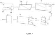
- Figure 3 shows a fabrication process of the battery cell 10.
- first, one or more sensor strips 106 are arranged on a first film P1.
- a width of the first film P1 generally corresponds to a height of the electrode assembly 12.
- the width of the first film P1 is generally equal to the height of the electrode assembly 12.
- the sensor strips 106 are arranged on the first film P1 in a manner that a longitudinal axis of the sensor strips 106 is inclined with respect to a longitudinal axis of the first film P1. The angle of inclination of the longitudinal axis of the sensor strips 106 with respect to the longitudinal axis of the first film P1 may be properly set as required.
- a second film P2 is covered on the first film P1 to sandwich and seal the sensor strips 106 between the first film P1 and the second film P2, so as to form a film assembly P, thereby avoiding corrosion of the sensor strips 106 by the electrolyte when the sensor strips 106 is embedded within the battery cell 10.
- the first film P1 and the second film P2 may be PP films, for example.
- the film assembly P in which the sensor strips 106 are sealed is wound around the outer peripheral surface of the electrode assembly 12, so that the sensor strips 106 are spirally wound around the outer peripheral surface of the electrode assembly 12.
- the film assembly P may be wound around the outer peripheral surface of the electrode assembly 12 by half circle, one circle or multiple circles as required.
- the film assembly P is wound around the electrode assembly 12 such that the sensor strips 106 are spirally wound around the outer peripheral surface of the electrode assembly 12 by two circles.
- the electrode assembly 12 with the sensor strips 106 wound around the outer peripheral surface is accommodated into the housing 11, to form the battery cell 10.
- This arrangement makes the sensor strips 106 to be embedded at multiple positions in the longitudinal direction and the circumferential direction between the electrode assembly 12 and the housing 11, so as to measure parameters of the battery cell 10 at multiple positions of the battery cell 10 in the longitudinal direction and the circumferential direction.
- a width of the first film P1 generally corresponds to a height of the electrode assembly 12, and the longitudinal axis of the sensor strips 106 is inclined with respect to the longitudinal axis of the first film P1, such that a width of the film assembly P generally corresponds to the height of the electrode assembly 12.
- the sensor strips 106 are spirally wound around the electrode assembly 12 at a predetermined pitch, and the electrode assembly obtained after winding has a substantially uniform outer contour.
- the present disclosure is not limited thereto.
- the width of the first film P1 may be set as required, as long as the first film P1 and the second film P2 can sandwich and seal the sensor strips 106, and spirally wind the sensor strips 106 around the outer peripheral surface of the electrode assembly 12.
- the battery cell 10 is a pouch battery cell
- the housing 11 is a flexible film, such as an aluminum foil or an aluminum-plastic film.
- the flexible film forming the housing 11 may form one of the pair of films sealing the sensor strips 106.
- the flexible film may be covered on the first film P1 to seal the sensor strips 106 between the first film P1 and the housing 11, without having to arrange the second film P2. Then, the housing 11 in which the sensor strips 106 are sealed is wound around the electrode assembly 12, to form the battery cell 10.
- the sensor strips 106 are embedded between the housing 11 and the electrode assembly 12, such that the sensor strips 106 can detect parameters of the battery cell 10 at multiple positions of the battery cell 10 in the transversal direction and the longitudinal direction, so as to accurately monitor the state of the battery cell 10 in a real time manner, thereby improving the safety of the battery cell 10.
- Figure 4 shows a battery cell 20 according to a second embodiment of the present disclosure
- Figure 5 shows a schematic diagram of the battery cell 20 of which a housing is removed.
- the battery cell 20 includes a housing 21 and an electrode assembly 22 accommodated in the housing 21.
- the battery cell 20 is a cylindrical battery cell.
- the housing 21 includes a housing body 211 and a cover assembly 212.
- the housing body 211 may be a steel or aluminum housing body.
- the battery cell 20 further includes one or more sensor strips 106 embedded between the electrode assembly 22 and the housing 21.
- the sensor strips 106 are spirally wound around an outer peripheral surface of the electrode assembly 22.
- the sensor strips 106 are FBG sensor strips, and may be used to measure the strain and the temperature.
- Figure 6 shows a fabrication process of the battery cell 20.
- first, one or more sensor strips 106 are arranged on a first film P1, such that a longitudinal axis of the sensor strips 106 is inclined with respect to a longitudinal axis of the first film P1.
- a second film P2 is covered on the first film P1 to seal the sensor strips 106 between the first film P1 and the second film P2, so as to form a film assembly P.
- the film assembly P is wound around the outer peripheral surface of the electrode assembly 22, so that the sensor strips 106 are spirally wound around the outer peripheral surface of the electrode assembly 22.
- the film assembly P may be wound around the outer peripheral surface of the electrode assembly 22 by half circle, one circle or multiple circles as required.
- the electrode assembly 22 with the sensor strips 106 wound around the outer peripheral surface is arranged in the housing body 211, and the cover assembly 212 is installed, so that the electrode assembly 22 is accommodated in the housing 21 to form the battery cell 20.
- This arrangement makes the sensor strips 106 to be embedded at multiple positions in the longitudinal direction and the circumferential direction between the electrode assembly 22 and the housing 21 (and more specifically, the housing body 211), so as to measure parameters of the battery cell 20 at multiple positions of the battery cell 20 in the longitudinal direction and the circumferential direction.
- the battery cell 20 according to the second embodiment of the present disclosure can achieve the above beneficial technical effects similar to the battery cell 10 according to the first embodiment of the present disclosure, and can accurately monitor the state of the battery cell 20 in a real time manner, thereby improving the safety of the battery cell 20.
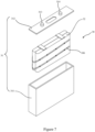
- FIG. 7 shows an exploded view of a battery cell 30 according to a third embodiment of the present disclosure.
- the battery cell 30 is a prismatic battery cell, and includes a housing 31 and an electrode assembly 32 accommodated in the housing 31.
- the housing 31 includes a housing body 311 and a cover plate 312. Electrode tabs 313 and 314 are arranged on the cover plate 312, and are respectively connected to corresponding electrodes of the electrode assembly 32.
- the battery cell 30 further includes one or more sensor strips 106 embedded between the electrode assembly 32 and the housing 31.
- the sensor strips 106 are spirally wound around an outer peripheral surface of the electrode assembly 32.
- the sensor strips 106 are FBG sensor strips, and may be used to measure the strain and the temperature.
- Figure 8 shows a fabrication process of the battery cell 30.
- first, one or more sensor strips 106 are arranged on a first film P1, such that a longitudinal axis of the sensor strips 106 is inclined with respect to a longitudinal axis of the first film P1.
- a second film P2 is covered on the first film P1 to seal the sensor strips 106 between the first film P1 and the second film P2, so as to form a film assembly P.
- the film assembly P is wound around the outer peripheral surface of the electrode assembly 32, so that the sensor strips 106 are spirally wound around the outer peripheral surface of the electrode assembly 32.
- the film assembly P may be wound around the outer peripheral surface of the electrode assembly 32 by half circle, one circle or multiple circles as required.
- the electrode assembly 32 with the sensor strips 106 wound around the outer peripheral surface is arranged in the housing body 311, and the cover assembly 312 is installed, so that the electrode assembly 32 is accommodated in the housing 31 to form the battery cell 30.
- This arrangement makes the sensor strips 106 to be embedded at multiple positions in the longitudinal direction and the circumferential direction between the electrode assembly 32 and the housing 31 (and more specifically, the housing body 311), so as to measure parameters of the battery cell 30 at multiple positions of the battery cell 30 in the longitudinal direction and the circumferential direction.
- the battery cell 30 according to the third embodiment of the present disclosure can achieve the above beneficial technical effects similar to the battery unit 10 according to the first embodiment of the present disclosure and the battery unit 20 according to the second embodiment of the present disclosure, and can accurately monitor the state of the battery cell 30 in a real time manner, thereby improving the safety of the battery cell 30.
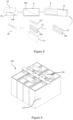
- FIG 9 shows a schematic diagram of a battery that is, for example, an aviation battery 100.
- the battery may be a battery used for ground applications, such as a battery for vehicle.
- the aviation battery 100 includes multiple battery cells 110 that are connected with each other (in parallel or in series).
- Figure 9 shows four battery cells 110 of the aviation battery 100 that are connected with each other in series via connectors 120.
- the present disclosure is not limited thereto, and in other examples according to the present disclosure, the aviation battery 100 may include more or less battery cells.
- the battery cells 110 are prismatic battery cells similar to the battery cell 30.
- the present disclosure is not limited thereto, and the battery cells 110 may be of the similar type to any one of the battery cell 10, the battery cell 20 and the battery cell 30.
- each battery cell in the aviation battery 100 may be detected at multiple positions of the battery cell.
- the sensor strips 106 of each battery cell detect the strain and the temperature at multiple positions of the battery cell, so as to timely detect the physico-chemical reaction state within the battery cell, which enables earlier detection of abnormality of single battery cells within the aviation battery 100, so as to trigger a corresponding alarm or a protective measure, thereby improving the safety of the aviation battery 100.
- a method for monitoring the aviation battery 100 includes receiving measurement data of the sensor strips 106 of each battery cell of the aviation battery 100; and determining a state of each battery cell within the aviation battery 100 based on the received measurement data, so as to detect the abnormality of each battery cell of the aviation battery 100 as early as possible, and trigger a corresponding alarm or protective measure, thereby preventing strain or heat generated by a single abnormal battery cell from propagating between neighboring battery cells and causing greater damage to the aviation battery 100.
- the method for monitoring the aviation battery 100 further includes detecting a voltage and/or a current of the aviation battery 100.
- the voltage and/or current of a single battery cell 110 may be measured, or the voltage and/or current of the entire aviation battery 100 may be measured.
- By measuring the strain and the temperature of each battery cell and combining the measurement of the voltage and/or current of the aviation battery 100 earlier detection of anomality of each battery cell 110 of the aviation battery 100 can be better achieved.
- Above method for monitoring the aviation battery 100 can be also used for other battery (such as, a battery for vehicle) including the battery cell 110.
Landscapes
- Chemical & Material Sciences (AREA)
- Chemical Kinetics & Catalysis (AREA)
- Electrochemistry (AREA)
- General Chemical & Material Sciences (AREA)
- Engineering & Computer Science (AREA)
- Manufacturing & Machinery (AREA)
- Physics & Mathematics (AREA)
- General Physics & Mathematics (AREA)
- Aviation & Aerospace Engineering (AREA)
- Sealing Battery Cases Or Jackets (AREA)
- Secondary Cells (AREA)
Abstract
Description
- The present disclosure relates to the battery field, and in particular to a battery cell, a battery cell fabrication method, an aviation battery, and a method for monitoring an aviation battery.
- The contents of this section only provide background information related to this disclosure, which may not constitute the prior art.
- Batteries are used widely in a variety of fields, for example, in ground applications such as electric vehicles and energy storage stations, as well as in a variety of applications in the aviation field. In various applications, the safety performance of batteries is of paramount importance. A commercial battery is generally formed by stacking multiple battery cells. The battery fails in a manner that a single battery cell fails first, which then rapidly causes the failure of neighboring battery cells and ultimately the failure of the entire battery. In the conventional technology, safety monitoring of the battery generally involves detection of signals of only the current, the voltage, and the temperature of the battery, and is performed on the entire battery, but lacks the detection of states of individual battery cells in the battery, failing to provide early warning of the failure of an individual cell, which may have caused a significant safety problem by the time the failure of the battery is detected. The safety requirement for batteries in the aviation field is higher than for conventional applications of batteries in other fields.
- Improving the state monitoring of batteries as well as improving the safety performance of batteries is an improvement direction in the field of batteries.
- It is an object of the present disclosure to improve the state monitoring of battery cells, so as to improve the safety performance of battery cells. It is another object of the present disclosure to improve the fabrication method of battery cells. It is still another object of the present disclosure to improve the monitoring method of aviation batteries, so as to improve the safety performance of the aviation battery.
- In an aspect of the present disclosure, a battery cell is provided, which comprises: a housing; and an electrode assembly accommodated in the housing. The battery cell further comprises one or more sensor strips, where the one or more sensor strips are embedded between the electrode assembly and the housing, and are spirally wound around an outer peripheral surface of the electrode assembly.
- By spirally winding the sensor strips around the outer peripheral surface of the electrode assembly, the sensor strips may be arranged at multiple positions in the longitudinal direction and the circumferential direction between the housing of the battery cell and the electrode assembly, so as to measure parameters of the battery cell at multiple positions in the longitudinal direction and the circumferential direction, thereby improving the state monitoring of the battery cell, facilitating early detection of the abnormality of the battery cell, and improving the safety in use of the battery cell.
- The sensor strips are optionally sealed between a pair of films.
- The sensor strips are optionally sealed before being spirally wound around the outer peripheral surface of the electrode assembly, such that the sensor strips are protected from being corroded by the electrolyte within the battery cell after the sensor strips are embedded within the battery cell.
- Optionally, a width of the pair of films corresponds to a height of the electrode assembly, and a longitudinal axis of the sensor strips is inclined with respect to a longitudinal axis of the pair of films.
- The above arrangement facilitates winding of the pair of films sandwiching the sensor strips around the outer peripheral surface of the electrode assembly, so that the sensor strips are spirally wound around the outer peripheral surface of the electrode assembly.
- The sensor strips optionally comprise a plurality of measurement points spaced apart from each other. The sensor strips optionally measure a strain and/or a temperature of the battery cell at each of the measurement points.
- By measuring the strain of the battery cell, the physico-chemical reaction state within the battery cell may be detected, which facilitates earlier identification of abnormality of the battery cell.
- Preferably, the sensor strips are FBG sensor strips.
- The battery cell is optionally a pouch battery cell, a cylindrical battery cell or a prismatic battery cell.
- Optionally, the battery cell is a pouch battery cell and the housing is a flexible film, the flexible film may form one of the pair of films.
- In another aspect of the present disclosure, a battery cell fabrication method is provided, which comprises: providing an electrode assembly of a battery cell; and accommodating the electrode assembly into a housing. The battery cell fabrication method further comprises: before accommodating the electrode assembly into the housing, spirally winding one or more sensor strips around an outer peripheral surface of the electrode assembly, so that the one or more sensor strips are embedded between the electrode assembly and the housing.
- The battery cell fabrication method further includes: before winding the one or more sensor strips around the outer peripheral surface of the electrode assembly, sealing the one or more sensor strips between a pair of films.
- Optionally, a width of the pair of films corresponds to a height of the electrode assembly, and a longitudinal axis of the sensor strips is inclined with respect to a longitudinal axis of the pair of films.
- Preferably, the sensor strips are FBG sensor strips.
- The battery cell is optionally a pouch battery cell, a cylindrical battery cell or a prismatic battery cell.
- Optionally, the battery cell is a pouch battery cell and the housing is a flexible film, the flexible film forms one of the pair of films.
- In another aspect of the present disclosure, an aviation battery is provided, which comprises one or more battery cells according to the present disclosure.
- In another aspect of the present disclosure, a method for monitoring an aviation battery is provided. The aviation battery comprises one or more battery cells according to the present disclosure. The method comprises: receiving measurement data of the one or more sensor strips of each battery cell of the aviation battery at a plurality of measurement points that are spaced apart from each other; and determining a state of each battery cell of the aviation battery based on the measurement data.
- The present disclosure provides a battery cell, a battery cell fabrication method, an aviation battery and a method for monitoring an aviation battery with improved safety performance, which can accurately detect the state of each battery cell in an aviation battery in a real time manner, so as to enable early detection of abnormality of a single battery cell, thereby improving the state monitoring of the battery cell, and improving the safety performance of the battery cell and the battery including the battery cell.
- The embodiments of the present disclosure will be described below with reference to the drawings by way of example. In the drawings, same features or components are indicated by same reference numerals, and the drawings may not be drawn to scale. In the drawings:
-
Figure 1 shows a schematic diagram of a battery cell according to a first embodiment of the present disclosure; -
Figure 2 shows a partial disassembly view of the battery cell shown inFigure 1 ; -
Figure 3 shows a fabrication process of the battery cell shown inFigure 1 ; -
Figure 4 shows a schematic diagram of a battery cell according to a second embodiment of the present disclosure; -
Figure 5 shows a schematic diagram of the battery cell shown inFigure 4 of which a housing is removed; -
Figure 6 shows a fabrication process of the battery cell shown inFigure 4 ; -
Figure 7 shows an exploded view of a battery cell according to a third embodiment of the present disclosure; -
Figure 8 shows a fabrication process of the battery cell shown inFigure 7 ; and -
Figure 9 shows a schematic diagram of an aviation battery of the present disclosure. - The following description is essentially illustrative, rather than intended to limit the present disclosure and the application or usage thereof. It should be appreciated that, throughout all the drawings, the same or similar parts or features are indicated by similar reference numerals. Each drawing only illustratively shows the concept and principle of the embodiments of the present disclosure, and does not necessarily show the specific dimensions and scales of various embodiments of the present disclosure. Specific parts in specific drawings may be exaggerated to illustrate related details or structures of embodiments of the present disclosure.
-
Figure 1 shows abattery cell 10 according to a first embodiment of the present disclosure, andFigure 2 shows a partial disassembly view of thebattery cell 10. As shown inFigures 1 and2 , thebattery cell 10 includes ahousing 11 and anelectrode assembly 12 accommodated in thehousing 11. Theelectrode assembly 12 includes multiple layers ofanode 101,cathode 102 and separatingfilm 103, where theseparating film 103 is sandwiched between theanode 101 and thecathode 102. Ananode tab 104 and acathode tab 105 are separately led out from theelectrode assembly 12 through thehousing 11. Thebattery cell 10 is a pouch battery cell. Thehousing 11 is a flexible film, such as an aluminum foil or an aluminum-plastic film. - As shown in the drawings, the
battery cell 10 further includes one ormore sensor strips 106 embedded between theelectrode assembly 12 and thehousing 11. The sensor strips 106 are flexible, and include multiple measurement points spaced apart from each other. The sensor strips 106 are spirally wound around an outer peripheral surface of theelectrode assembly 12. This arrangement makes the sensor strips 106 to be in contact with theelectrode assembly 12 at multiple positions in a longitudinal direction and a circumferential direction. When theelectrode assembly 12 and thehousing 11 are assembled in position, the sensor strips 106 are embedded at multiple positions in the longitudinal direction and the circumferential direction between thehousing 11 and theelectrode assembly 12, such that parameters of thebattery cell 10 can be detected at multiple measurement points that are spaced apart from each other, which is particularly advantageous when theelectrode assembly 12 is a wound electrode assembly, since different positions of thebattery cell 10 are subject to widely varying stresses during the charging and discharging processes of thebattery cell 10. By detecting parameters of thebattery cell 10 at multiple different positions, the actual state of thebattery unit 10 can be determined accurately in a real time manner. - Preferably, the sensor strips 106 detect a strain and/or a temperature of the
battery cell 10 at each of the measurement points of the sensor strips 106. For example, at one of the measurement points, both the strain and the temperature are measured, and at another one of the measurement points, only one of the strain and temperature is measured. Preferably, the sensor strips 106 are FBG (Fibre Bragg Grating) sensor strips, and may be used to measure the strain and the temperature. The strain state within the battery cell generally reflects the physico-chemical reaction state within the battery cell. Before the battery cell fails, the battery cell generally generates gas and/or heat, which causes an abnormal increase of strains. Therefore, the physico-chemical reaction state within thebattery cell 10 may be detected by measuring the strain of thebattery unit 10, which facilitates earlier identification of the failure of thebattery cell 10. - In addition, the sensor strips 106 are sealed to prevent the sensor strips 106 from being corroded by the electrolyte within the
battery cell 10. In an example, the sensor strips 106 may be sealed between a pair of films, such as a pair of PP films. -
Figure 3 shows a fabrication process of thebattery cell 10. As shown inFigure 3 , first, one or more sensor strips 106 are arranged on a first film P1. In the example shown in the drawings, a width of the first film P1 generally corresponds to a height of theelectrode assembly 12. For example, the width of the first film P1 is generally equal to the height of theelectrode assembly 12. The sensor strips 106 are arranged on the first film P1 in a manner that a longitudinal axis of the sensor strips 106 is inclined with respect to a longitudinal axis of the first film P1. The angle of inclination of the longitudinal axis of the sensor strips 106 with respect to the longitudinal axis of the first film P1 may be properly set as required. Then, a second film P2 is covered on the first film P1 to sandwich and seal the sensor strips 106 between the first film P1 and the second film P2, so as to form a film assembly P, thereby avoiding corrosion of the sensor strips 106 by the electrolyte when the sensor strips 106 is embedded within thebattery cell 10. The first film P1 and the second film P2 may be PP films, for example. Next, the film assembly P in which the sensor strips 106 are sealed is wound around the outer peripheral surface of theelectrode assembly 12, so that the sensor strips 106 are spirally wound around the outer peripheral surface of theelectrode assembly 12. The film assembly P may be wound around the outer peripheral surface of theelectrode assembly 12 by half circle, one circle or multiple circles as required. In the example shown in the drawings, the film assembly P is wound around theelectrode assembly 12 such that the sensor strips 106 are spirally wound around the outer peripheral surface of theelectrode assembly 12 by two circles. Finally, theelectrode assembly 12 with the sensor strips 106 wound around the outer peripheral surface is accommodated into thehousing 11, to form thebattery cell 10. This arrangement makes the sensor strips 106 to be embedded at multiple positions in the longitudinal direction and the circumferential direction between theelectrode assembly 12 and thehousing 11, so as to measure parameters of thebattery cell 10 at multiple positions of thebattery cell 10 in the longitudinal direction and the circumferential direction. - In the example shown in the drawings, only one
sensor strip 106 sandwiched between the first film P1 and the second film P2 is shown. However, the present disclosure is not limited thereto. In other examples according to the present disclosure, multiple sensor strips 106 arranged side by side and spaced apart from each other may be provided. - In the example shown in the drawings, a width of the first film P1 generally corresponds to a height of the
electrode assembly 12, and the longitudinal axis of the sensor strips 106 is inclined with respect to the longitudinal axis of the first film P1, such that a width of the film assembly P generally corresponds to the height of theelectrode assembly 12. In a case that the film assembly P is wound around the outer peripheral surface of theelectrode assembly 12, the sensor strips 106 are spirally wound around theelectrode assembly 12 at a predetermined pitch, and the electrode assembly obtained after winding has a substantially uniform outer contour. However, the present disclosure is not limited thereto. In other examples according to the present disclosure, the width of the first film P1 may be set as required, as long as the first film P1 and the second film P2 can sandwich and seal the sensor strips 106, and spirally wind the sensor strips 106 around the outer peripheral surface of theelectrode assembly 12. - In addition, in the example shown in
Figures 1 to 3 , thebattery cell 10 is a pouch battery cell, thehousing 11 is a flexible film, such as an aluminum foil or an aluminum-plastic film. In the procedure of sealing the sensor strips 106, the flexible film forming thehousing 11 may form one of the pair of films sealing the sensor strips 106. For example, the flexible film may be covered on the first film P1 to seal the sensor strips 106 between the first film P1 and thehousing 11, without having to arrange the second film P2. Then, thehousing 11 in which the sensor strips 106 are sealed is wound around theelectrode assembly 12, to form thebattery cell 10. - In the
battery cell 10 according to the present disclosure, the sensor strips 106 are embedded between thehousing 11 and theelectrode assembly 12, such that the sensor strips 106 can detect parameters of thebattery cell 10 at multiple positions of thebattery cell 10 in the transversal direction and the longitudinal direction, so as to accurately monitor the state of thebattery cell 10 in a real time manner, thereby improving the safety of thebattery cell 10. -
Figure 4 shows abattery cell 20 according to a second embodiment of the present disclosure, andFigure 5 shows a schematic diagram of thebattery cell 20 of which a housing is removed. - As shown in
Figures 4 and 5 , thebattery cell 20 includes ahousing 21 and anelectrode assembly 22 accommodated in thehousing 21. Thebattery cell 20 is a cylindrical battery cell. Thehousing 21 includes ahousing body 211 and acover assembly 212. Thehousing body 211 may be a steel or aluminum housing body. Thebattery cell 20 further includes one or more sensor strips 106 embedded between theelectrode assembly 22 and thehousing 21. As shown inFigure 5 , the sensor strips 106 are spirally wound around an outer peripheral surface of theelectrode assembly 22. Preferably, the sensor strips 106 are FBG sensor strips, and may be used to measure the strain and the temperature. -
Figure 6 shows a fabrication process of thebattery cell 20. As shown inFigure 6 , similar to the fabrication process of thebattery cell 10 shown inFigure 3 , first, one or more sensor strips 106 are arranged on a first film P1, such that a longitudinal axis of the sensor strips 106 is inclined with respect to a longitudinal axis of the first film P1. Then, a second film P2 is covered on the first film P1 to seal the sensor strips 106 between the first film P1 and the second film P2, so as to form a film assembly P. Next, the film assembly P is wound around the outer peripheral surface of theelectrode assembly 22, so that the sensor strips 106 are spirally wound around the outer peripheral surface of theelectrode assembly 22. The film assembly P may be wound around the outer peripheral surface of theelectrode assembly 22 by half circle, one circle or multiple circles as required. Finally, theelectrode assembly 22 with the sensor strips 106 wound around the outer peripheral surface is arranged in thehousing body 211, and thecover assembly 212 is installed, so that theelectrode assembly 22 is accommodated in thehousing 21 to form thebattery cell 20. This arrangement makes the sensor strips 106 to be embedded at multiple positions in the longitudinal direction and the circumferential direction between theelectrode assembly 22 and the housing 21 (and more specifically, the housing body 211), so as to measure parameters of thebattery cell 20 at multiple positions of thebattery cell 20 in the longitudinal direction and the circumferential direction. - The
battery cell 20 according to the second embodiment of the present disclosure can achieve the above beneficial technical effects similar to thebattery cell 10 according to the first embodiment of the present disclosure, and can accurately monitor the state of thebattery cell 20 in a real time manner, thereby improving the safety of thebattery cell 20. -
Figure 7 shows an exploded view of abattery cell 30 according to a third embodiment of the present disclosure. As shown inFigure 7 , thebattery cell 30 is a prismatic battery cell, and includes ahousing 31 and anelectrode assembly 32 accommodated in thehousing 31. Thehousing 31 includes ahousing body 311 and acover plate 312.Electrode tabs cover plate 312, and are respectively connected to corresponding electrodes of theelectrode assembly 32. Thebattery cell 30 further includes one or more sensor strips 106 embedded between theelectrode assembly 32 and thehousing 31. As shown inFigure 7 , the sensor strips 106 are spirally wound around an outer peripheral surface of theelectrode assembly 32. Preferably, the sensor strips 106 are FBG sensor strips, and may be used to measure the strain and the temperature. -
Figure 8 shows a fabrication process of thebattery cell 30. As shown inFigure 8 , similar to the fabrication processes of thebattery cell 10 and thebattery cell 20 described above, first, one or more sensor strips 106 are arranged on a first film P1, such that a longitudinal axis of the sensor strips 106 is inclined with respect to a longitudinal axis of the first film P1. Then, a second film P2 is covered on the first film P1 to seal the sensor strips 106 between the first film P1 and the second film P2, so as to form a film assembly P. Next, the film assembly P is wound around the outer peripheral surface of theelectrode assembly 32, so that the sensor strips 106 are spirally wound around the outer peripheral surface of theelectrode assembly 32. The film assembly P may be wound around the outer peripheral surface of theelectrode assembly 32 by half circle, one circle or multiple circles as required. Finally, theelectrode assembly 32 with the sensor strips 106 wound around the outer peripheral surface is arranged in thehousing body 311, and thecover assembly 312 is installed, so that theelectrode assembly 32 is accommodated in thehousing 31 to form thebattery cell 30. This arrangement makes the sensor strips 106 to be embedded at multiple positions in the longitudinal direction and the circumferential direction between theelectrode assembly 32 and the housing 31 (and more specifically, the housing body 311), so as to measure parameters of thebattery cell 30 at multiple positions of thebattery cell 30 in the longitudinal direction and the circumferential direction. - The
battery cell 30 according to the third embodiment of the present disclosure can achieve the above beneficial technical effects similar to thebattery unit 10 according to the first embodiment of the present disclosure and thebattery unit 20 according to the second embodiment of the present disclosure, and can accurately monitor the state of thebattery cell 30 in a real time manner, thereby improving the safety of thebattery cell 30. -
Figure 9 shows a schematic diagram of a battery that is, for example, anaviation battery 100. Alternatively, the battery may be a battery used for ground applications, such as a battery for vehicle. Theaviation battery 100 includesmultiple battery cells 110 that are connected with each other (in parallel or in series).Figure 9 shows fourbattery cells 110 of theaviation battery 100 that are connected with each other in series viaconnectors 120. However, the present disclosure is not limited thereto, and in other examples according to the present disclosure, theaviation battery 100 may include more or less battery cells. In addition, inFigure 9 , thebattery cells 110 are prismatic battery cells similar to thebattery cell 30. However, the present disclosure is not limited thereto, and thebattery cells 110 may be of the similar type to any one of thebattery cell 10, thebattery cell 20 and thebattery cell 30. - Since each of the
battery cells 110 of theaviation battery 100 includes the sensor strips 106 embedded therein, each battery cell in theaviation battery 100 may be detected at multiple positions of the battery cell. Preferably, the sensor strips 106 of each battery cell detect the strain and the temperature at multiple positions of the battery cell, so as to timely detect the physico-chemical reaction state within the battery cell, which enables earlier detection of abnormality of single battery cells within theaviation battery 100, so as to trigger a corresponding alarm or a protective measure, thereby improving the safety of theaviation battery 100. A method for monitoring theaviation battery 100 includes receiving measurement data of the sensor strips 106 of each battery cell of theaviation battery 100; and determining a state of each battery cell within theaviation battery 100 based on the received measurement data, so as to detect the abnormality of each battery cell of theaviation battery 100 as early as possible, and trigger a corresponding alarm or protective measure, thereby preventing strain or heat generated by a single abnormal battery cell from propagating between neighboring battery cells and causing greater damage to theaviation battery 100. - The method for monitoring the
aviation battery 100 further includes detecting a voltage and/or a current of theaviation battery 100. For example, the voltage and/or current of asingle battery cell 110 may be measured, or the voltage and/or current of theentire aviation battery 100 may be measured. By measuring the strain and the temperature of each battery cell and combining the measurement of the voltage and/or current of theaviation battery 100, earlier detection of anomality of eachbattery cell 110 of theaviation battery 100 can be better achieved. Above method for monitoring theaviation battery 100 can be also used for other battery (such as, a battery for vehicle) including thebattery cell 110. - Exemplary embodiments of a battery cell, a battery cell fabrication method, an aviation battery, and a method for monitoring an aviation battery of the present disclosure have been described herein in detail in connection with the accompanying drawings. However, it should be understood that the present disclosure is not limited to the specific embodiments described and illustrated in detail above. Without departing from the spirit and scope of the present disclosure, those skilled in the art can make various modifications and variations to the present disclosure. All the variations and modifications shall fall within the scope of the present disclosure. Moreover, all the components described herein can be replaced by other technically equivalent components.
Claims (15)
- A battery cell (10, 20, 30), comprising:a housing (11, 21, 31); andan electrode assembly (12, 22, 32) accommodated in the housing (11, 21, 31),characterized in that the battery cell (10, 20, 30) further comprises one or more sensor strips (106), wherein the one or more sensor strips (106) are embedded between the electrode assembly (12, 22, 32) and the housing (11, 21, 31), and are spirally wound around an outer peripheral surface of the electrode assembly (12, 22, 32).
- The battery cell (10, 20, 30) according to claim 1, wherein the sensor strips (106) are sealed between a pair of films.
- The battery cell (10, 20, 30) according to claim 2, wherein a width of the pair of films corresponds to a height of the electrode assembly (10, 20, 30), and a longitudinal axis of the sensor strips (106) is inclined with respect to a longitudinal axis of the pair of films.
- The battery cell (10, 20, 30) according to claim 1, wherein the sensor strips (106) comprise a plurality of measurement points spaced apart from each other, and the sensor strips (106) measure a strain and/or a temperature of the battery cell (10, 20, 30) at each of the measurement points.
- The battery cell (10, 20, 30) according to any one of claims 1 to 4, wherein the sensor strips (106) are FBG sensor strips.
- The battery cell (10, 20, 30) according to any one of claims 1 to 4, wherein the battery cell (10, 20, 30) is a pouch battery cell, a cylindrical battery cell or a prismatic battery cell.
- The battery cell (10) according to claim 2, wherein the battery cell (10) is a pouch battery cell, the housing (11) is a flexible film, and the flexible film forms one of the pair of films.
- A battery cell fabrication method, comprising:providing an electrode assembly (12, 22, 32) of a battery cell (10, 20, 30); andaccommodating the electrode assembly (12, 22, 32) into a housing (11, 21, 31),characterized in that the battery cell fabrication method further comprises: before accommodating the electrode assembly (12, 22, 32) into the housing (11, 21, 31), spirally winding one or more sensor strips (106) around an outer peripheral surface of the electrode assembly (12, 22, 32), so that the one or more sensor strips (106) are embedded between the electrode assembly (12, 22, 32) and the housing (11, 21, 31).
- The battery cell fabrication method according to claim 8, further comprising: before winding the one or more sensor strips (106) around the outer peripheral surface of the electrode assembly (12, 22, 32), sealing the one or more sensor strips (106) between a pair of films.
- The battery cell fabrication method according to claim 9, wherein a width of the pair of films corresponds to a height of the electrode assembly (12, 22, 32), and a longitudinal axis of the sensor strips (106) is inclined with respect to a longitudinal axis of the pair of films.
- The battery cell fabrication method according to any one of claims 8 to 10, wherein the sensor strips (106) are FBG sensor strips.
- The battery cell fabrication method according to any one of claims 8 to 10, wherein the battery cell (10, 20, 30) is a pouch battery cell, a cylindrical battery cell or a prismatic battery cell.
- The battery cell fabrication method according to claim 9, wherein the battery cell (10) is a pouch battery cell, the housing (11) is a flexible film, and the flexible film forms one of the pair of films.
- An aviation battery (100) characterized by comprising one or more battery cells (10, 20, 30) according to any one of claims 1 to 7.
- A method for monitoring an aviation battery (100), wherein the aviation battery (100) comprises one or more battery cells (10, 20, 30) according to any one of claims 1 to 7,
characterized in that the method comprises:receiving measurement data of the one or more sensor strips (106) of each battery cell (10, 20, 30) of the aviation battery (100) at a plurality of measurement points that are spaced apart from each other; anddetermining a state of each battery cell (10, 20, 30) of the aviation battery (100) based on the measurement data.
Applications Claiming Priority (1)
| Application Number | Priority Date | Filing Date | Title |
|---|---|---|---|
| CN202311595813.5A CN120049033A (en) | 2023-11-27 | 2023-11-27 | Battery unit, battery unit manufacturing method, aviation battery and aviation battery monitoring method |
Publications (2)
| Publication Number | Publication Date |
|---|---|
| EP4560782A2 true EP4560782A2 (en) | 2025-05-28 |
| EP4560782A3 EP4560782A3 (en) | 2025-07-09 |
Family
ID=93651360
Family Applications (1)
| Application Number | Title | Priority Date | Filing Date |
|---|---|---|---|
| EP24215154.6A Pending EP4560782A3 (en) | 2023-11-27 | 2024-11-25 | Battery cell, battery cell fabrication method, aviation battery, and method for monitoring aviation battery |
Country Status (3)
| Country | Link |
|---|---|
| US (1) | US20250174850A1 (en) |
| EP (1) | EP4560782A3 (en) |
| CN (1) | CN120049033A (en) |
Family Cites Families (2)
| Publication number | Priority date | Publication date | Assignee | Title |
|---|---|---|---|---|
| DE602006012940D1 (en) * | 2005-01-20 | 2010-04-29 | Philips Intellectual Property | ARRANGEMENT AND METHOD FOR PRESSURE MONITORING IN A BATTERY CELL |
| CN106410307A (en) * | 2016-10-13 | 2017-02-15 | 江汉大学 | Lithium battery safety real-time monitoring system |
-
2023
- 2023-11-27 CN CN202311595813.5A patent/CN120049033A/en active Pending
-
2024
- 2024-11-25 US US18/958,428 patent/US20250174850A1/en active Pending
- 2024-11-25 EP EP24215154.6A patent/EP4560782A3/en active Pending
Also Published As
| Publication number | Publication date |
|---|---|
| US20250174850A1 (en) | 2025-05-29 |
| EP4560782A3 (en) | 2025-07-09 |
| CN120049033A (en) | 2025-05-27 |
Similar Documents
| Publication | Publication Date | Title |
|---|---|---|
| JP6049867B2 (en) | Cover film for galvanic element, electrochemical power storage device, electrochemical power storage system, flexible film for galvanic element cover, and method for calculating state parameters of electrochemical power storage device | |
| EP3442073B1 (en) | Battery cell capable of measuring internal temperature | |
| US20250189596A1 (en) | Battery system diagnosing apparatus and method | |
| US20120148890A1 (en) | Battery system | |
| JP2016126943A (en) | Power storage device and power storage system | |
| KR102573797B1 (en) | Battery system and method for determining abnormality of battery | |
| KR102872129B1 (en) | Apparatus and method for diagnosing battery system | |
| EP4485619A1 (en) | Battery pack, electric apparatus, battery pack test method and computer storage medium | |
| KR102886237B1 (en) | Method for detecting abnormal battery through relative comparison | |
| JP2006269345A (en) | Overvoltage detecting method, device, and battery pack | |
| US20230344022A1 (en) | Battery and energy storage system | |
| US10020546B2 (en) | Device for managing an accumulator | |
| US20130252051A1 (en) | Battery system | |
| CN116845406B (en) | Battery and electricity utilization device | |
| KR20230055871A (en) | Battery module with a pressure sensor for thermal runaway detection | |
| US20250174850A1 (en) | Battery cell, battery cell fabrication method, aviation battery, and method for monitoring aviation battery | |
| US10847980B2 (en) | Battery module | |
| JP2019145342A (en) | Diagnostic device and control device | |
| CN104538694A (en) | Lithium battery pack monitoring system and lithium battery pack monitoring method based on electrical impedance imaging technology | |
| US12025578B2 (en) | Welding failure inspection method | |
| JP4656677B2 (en) | Deteriorated battery detector | |
| KR20230059516A (en) | Battery module and battery pack monitoring the insulation of pouch-type battery cells | |
| CN114695925A (en) | Abnormality detection method and apparatus for vehicle-mounted fuel cell, and vehicle | |
| CN114597337B (en) | Battery pole piece and power battery | |
| CN118533333A (en) | Implantable packaging-free thin-film pressure sensor, implantable sensor cell, battery module, electronic device and energy storage device |
Legal Events
| Date | Code | Title | Description |
|---|---|---|---|
| PUAI | Public reference made under article 153(3) epc to a published international application that has entered the european phase |
Free format text: ORIGINAL CODE: 0009012 |
|
| STAA | Information on the status of an ep patent application or granted ep patent |
Free format text: STATUS: THE APPLICATION HAS BEEN PUBLISHED |
|
| AK | Designated contracting states |
Kind code of ref document: A2 Designated state(s): AL AT BE BG CH CY CZ DE DK EE ES FI FR GB GR HR HU IE IS IT LI LT LU LV MC ME MK MT NL NO PL PT RO RS SE SI SK SM TR |
|
| PUAL | Search report despatched |
Free format text: ORIGINAL CODE: 0009013 |
|
| AK | Designated contracting states |
Kind code of ref document: A3 Designated state(s): AL AT BE BG CH CY CZ DE DK EE ES FI FR GB GR HR HU IE IS IT LI LT LU LV MC ME MK MT NL NO PL PT RO RS SE SI SK SM TR |
|
| RIC1 | Information provided on ipc code assigned before grant |
Ipc: H01M 50/105 20210101ALI20250605BHEP Ipc: H01M 10/42 20060101ALI20250605BHEP Ipc: H01M 50/569 20210101ALI20250605BHEP Ipc: H01M 10/48 20060101AFI20250605BHEP |
|
| STAA | Information on the status of an ep patent application or granted ep patent |
Free format text: STATUS: REQUEST FOR EXAMINATION WAS MADE |
|
| 17P | Request for examination filed |
Effective date: 20260102 |