EP4560625A2 - Zeitumkehr-ecu-synthese - Google Patents
Zeitumkehr-ecu-synthese Download PDFInfo
- Publication number
- EP4560625A2 EP4560625A2 EP25162237.9A EP25162237A EP4560625A2 EP 4560625 A2 EP4560625 A2 EP 4560625A2 EP 25162237 A EP25162237 A EP 25162237A EP 4560625 A2 EP4560625 A2 EP 4560625A2
- Authority
- EP
- European Patent Office
- Prior art keywords
- subframe
- phase
- peaks
- peak
- concealment
- Prior art date
- Legal status (The legal status is an assumption and is not a legal conclusion. Google has not performed a legal analysis and makes no representation as to the accuracy of the status listed.)
- Pending
Links
Images


Classifications
-
- G—PHYSICS
- G10—MUSICAL INSTRUMENTS; ACOUSTICS
- G10L—SPEECH ANALYSIS TECHNIQUES OR SPEECH SYNTHESIS; SPEECH RECOGNITION; SPEECH OR VOICE PROCESSING TECHNIQUES; SPEECH OR AUDIO CODING OR DECODING
- G10L19/00—Speech or audio signals analysis-synthesis techniques for redundancy reduction, e.g. in vocoders; Coding or decoding of speech or audio signals, using source filter models or psychoacoustic analysis
- G10L19/005—Correction of errors induced by the transmission channel, if related to the coding algorithm
-
- G—PHYSICS
- G10—MUSICAL INSTRUMENTS; ACOUSTICS
- G10L—SPEECH ANALYSIS TECHNIQUES OR SPEECH SYNTHESIS; SPEECH RECOGNITION; SPEECH OR VOICE PROCESSING TECHNIQUES; SPEECH OR AUDIO CODING OR DECODING
- G10L19/00—Speech or audio signals analysis-synthesis techniques for redundancy reduction, e.g. in vocoders; Coding or decoding of speech or audio signals, using source filter models or psychoacoustic analysis
- G10L19/02—Speech or audio signals analysis-synthesis techniques for redundancy reduction, e.g. in vocoders; Coding or decoding of speech or audio signals, using source filter models or psychoacoustic analysis using spectral analysis, e.g. transform vocoders or subband vocoders
- G10L19/022—Blocking, i.e. grouping of samples in time; Choice of analysis windows; Overlap factoring
-
- G—PHYSICS
- G10—MUSICAL INSTRUMENTS; ACOUSTICS
- G10L—SPEECH ANALYSIS TECHNIQUES OR SPEECH SYNTHESIS; SPEECH RECOGNITION; SPEECH OR VOICE PROCESSING TECHNIQUES; SPEECH OR AUDIO CODING OR DECODING
- G10L19/00—Speech or audio signals analysis-synthesis techniques for redundancy reduction, e.g. in vocoders; Coding or decoding of speech or audio signals, using source filter models or psychoacoustic analysis
- G10L19/04—Speech or audio signals analysis-synthesis techniques for redundancy reduction, e.g. in vocoders; Coding or decoding of speech or audio signals, using source filter models or psychoacoustic analysis using predictive techniques
- G10L19/06—Determination or coding of the spectral characteristics, e.g. of the short-term prediction coefficients
Definitions
- the present disclosure relates generally to communications, and more particularly to methods and apparatuses for controlling a packet loss concealment for mono, stereo or multichannel audio encoding and decoding.
- PLC Packet Loss Concealment techniques
- FEC Frame Error Concealment
- FLC Frame Loss Concealment
- ECU Error Concealment Unit
- a time domain PLC similar to the LP based PLC, may be suitable.
- the FD PLC may mimic an LP decoder by estimating LP parameters and an excitation signal based on the last received frame [2].
- the last received frame may be repeated in spectral domain where the coefficients are multiplied to a random sign signal to reduce the metallic sound of a repeated signal.
- a generic error concealment method operating in the frequency domain is the Phase ECU (Error Concealment Unit) [4].
- the Phase ECU is a stand-alone tool operating on a buffer of the previously decoded and reconstructed time domain signal.
- the framework of the Phase ECU is based on the sinusoidal analysis and synthesis paradigm. In this method, the sinusoid components of the last good frame may be extracted and phase shifted. When a frame is lost, the sinusoid frequencies are obtained in DFT (discrete Fourier transform) domain from the past decoded synthesis. First, the corresponding frequency bins are identified by finding the peaks of the magnitude spectrum plane. Then, fractional frequencies of the peaks are estimated using peak frequency bins.
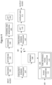
- the concept of the Phase ECU may be used in decoders operating in frequency domain. This concept includes encoding and decoding systems which perform the decoding in frequency domain, as illustrated in Figure 1 , but also decoders which perform time domain decoding with additional frequency domain processing as illustrated in Figure 2 .
- the time domain input audio signal (sub)frames are windowed 100 and transformed to frequency domain by DFT 101.
- An encoder 102 performs encoding in frequency domain and provides encoded parameters for transmission 103.
- a decoder 104 decodes received frames or applies PLC 109 in case a frame loss. In the construction of the concealment frame, the PLC may use a memory 108 of previously decoded frames.
- FIG. 2 illustrates an encoder and decoder pair where the decoder applies a DFT transform to facilitate frequency domain processing.
- Received and decoded time domain signal is first (sub)frame wise windowed 105 and then transformed to frequency domain by DFT 106 for frequency domain processing 107 that may be done either before or after PLC 109 (in case a frame loss).
- the window re-dressing solution where the windowing is inversed and reapplied, overcomes the issue of the different spectral signatures since the ECU may be based on a single subframe.
- applying the inverted window and applying a new window involves a division and a multiplication for each sample, where the division is a computationally complex operation and computationally expensive.
- This solution could be improved by storing a precomputed re-dressing window in memory, but this would increase the required table memory.
- the ECU is applied on a subpart of the spectrum, it may further require that the full spectrum is re-dressed since the full spectrum needs to have the same window shape.
- an audio decoding method is proved to generate a concealment audio subframe of an audio signal in a decoding device.
- the method comprises generating frequency spectra on a subframe basis where consecutive subframes of the audio signal have a property that an applied window shape of first subframe of the consecutive subframes is a mirrored version or a time reversed version of a second subframe of the consecutive subframes.
- the method further comprises obtaining the previously generated signal spectrum, detecting peaks of a signal spectrum, estimating a phase of each of the peaks and deriving a phase adjustment to apply to the peaks of the signal spectrum based on the estimated phase to form time reversed phase adjusted peaks.
- a potential advantage provided is that a multi-subframe ECU is generated from a single subframe spectrum by applying a reversed time synthesis. This generating may be suited for cases where the subframe windows are time reversed versions of each other. Generating all ECU frames from a single stored decoded frame ensures that the subframes have a similar spectral signature, while keeping the memory footprint and computational complexity at a minimum.
- an audio decoder is proved.
- the audio decoder is configured to perform the method of the first aspect.
- FIG. 9 is a block diagram illustrating elements of a decoder device 900, which may be part of a mobile terminal, a mobile communication terminal, a wireless communication device, a wireless terminal, a wireless communication terminal, user equipment, UE, a user equipment node/terminal/device, etc., configured to provide wireless communication according to embodiments.
- decoder 900 may include a network interface circuit 906 (also referred to as a network interface) configured to provide communications with other devices/entities/functions/etc.
- the decoder 900 may also include a processor circuit 902 (also referred to as a processor) operatively coupled to the network interface circuit 906, and a memory circuit 904 (also referred to as memory) operatively coupled to the processor circuit.
- the memory circuit 904 may include computer readable program code that when executed by the processor circuit 902 causes the processor circuit to perform operations according to embodiments disclosed herein.
- processor circuit 902 may be defined to include memory so that a separate memory circuit is not required.
- operations of the decoder 900 may be performed by processor 902 and/or network interface 906.
- processor 902 may control network interface 906 to transmit communications to multichannel audio players and/or to receive communications through network interface 906 from one or more other network nodes/entities/servers such as encoder nodes, depository servers, etc.
- modules may be stored in memory 904, and these modules may provide instructions so that when instructions of a module are executed by processor 902, processor 902 performs respective operations.
- subframe notation shall be used to describe the embodiments.
- a subframe denotes a part of a larger frame where the larger frame is composed of a set of subframes.
- the embodiments described may also be used with frame notation.
- the subframes may form groups of frames that have the same window shape as described herein and subframes do not need to be part of a larger frame.
- the consecutive subframes may have the property that the applied window shape is mirrored or time reversed versions of each other, as illustrated in Figure 3 , where subframe 2 is a mirrored or time reversed version of subframe 1.
- the decoder obtains the spectra of the reconstructed subframes X ⁇ 1 ( m, k ), X ⁇ 2 ( m, k) for each frame m.
- the subframe spectra may be obtained from a reconstructed time domain synthesis x ⁇ ( m, n), where n is a sample index.
- the dashed boxes in Figure 2 indicate that the frequency domain processing may be done either before or after the memory and PLC modules.
- the subframe windowing functions w 1 ( n ) and w 2 ( n ) are mirrored or time reversed versions of each other.
- the subframe spectra are obtained from a decoder time domain synthesis, similar to the system outlined in Figure 2 . It should be noted that the embodiments are equally applicable for a system where the decoder reconstructs the subframe spectra directly, as outlined in Figure 1 .
- the spectrum corresponding to the second subframe X ⁇ 2 ( m, k ) is stored in memory.
- X ⁇ mem k : X ⁇ 2 m k
- the peaks of the spectrum are modelled with sinusoids with a certain amplitude, frequency and phase.
- Each peak may be associated with a number of frequency bins representing the peak. These are found by rounding the fractional frequency to the closest integer and including the neighboring bins, e.g.
- [ ⁇ ] represents the rounding operation
- G i is the group of bins representing the peak at frequency f i .
- the number N near is a tuning constant that may be determined when designing the system.
- a larger N near provides higher accuracy in each peak representation, but also introduces a larger distance between peaks that may be modeled.
- a suitable value for N near may be 1 or 2.
- the peaks of the concealment spectrum X ⁇ ECU ( m, k ) may be formed by using these groups of bins, where a phase adjustment has been applied to each group.
- the phase adjustment accounts for the change in phase in the underlying sinusoid, assuming that the frequency remains the same between the last correctly received and decoded frame and the concealment frame.
- the phase adjustment is based on the fractional frequency and the number of samples between the analysis frame of the previous frame and where the current frame would start. As illustrated in Figure 3 , this number of samples is N step 21 between the start of the second subframe of the last received frame and the start of the first subframe of the first ECU frame, and N full between the first subframe of the last received frame and the first subframe of the first ECU frame. Note that N full also gives the distance between the second subframe of the last received frame and the second subframe of the first ECU frame.
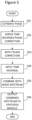
- FIG. 5 is a flowchart illustrating the steps of time reversed ECU synthesis described below.
- the ECU synthesis may be done in reversed time to obtain the desired window shape.
- N lost - 1 N full handles the phase progression for burst errors, where the step is incremented with the frame length of the full frame N full .
- N lost 1.
- the peaks of the concealment spectrum may be formed by applying the phase adjustment to the stored spectrum in operation 503.
- X ⁇ ECU m k X ⁇ mem k e j ⁇ ⁇ i * , k ⁇ G i
- the asterisk '*' denotes the complex conjugate, which gives a time reversal of the signal in operation 504. This results in a time reversal of the first ECU subframe. It should be noted that it may also be possible to perform the reversal in time domain after inverse DFT. However, if X ⁇ ECU ( m, k) only represents a part of the complete spectrum this requires that the remaining spectrum is pretreated e.g. by a time reversal before the DFT analysis.
- the remaining bins may also be populated with spectral coefficients that retain a desired property of the signal, e.g. correlation with a second channel in a multichannel decoder system.
- the peak spectrum X ⁇ ECU (m, k), where k ⁇ G i is combined with the noise spectrum X ⁇ ECU ( m, k ), where k ⁇ G i to form a combined spectrum.
- the regular phase adjustment may be used.
- ⁇ ⁇ i 2 ⁇ f i N full N lost / N
- the combined concealment spectrum may be fed to the following processing steps in operation 506, including inverse DFT and an overlap-add operation which results in an output audio signal.
- the output audio signal may be transmitted to one or more speakers such as loudspeakers for playback.
- the speakers may be part of the decoding device, be a separate device, or part of another device.
- phase For a time-reversed continuation of the sinusoid, the phase needs to be mirrored in the real axis by applying the complex conjugate or by simply taking the negative phase - ⁇ 1 . Since this phase angle now represents the endpoint of the ECU synthesis frame, the phase needs to be wound back by the length of the analysis frame to get to the desired start phase ⁇ 2 .
- ⁇ 2 ⁇ ⁇ 1 ⁇ 2 ⁇ f N ⁇ 1 / N
- the desired time reversal can be achieved in DFT domain by using a complex conjugate together with a one-sample circular shift.
- This circular shift can be implemented with a phase correction of 2 ⁇ k / N which may be included in the final phase correction.
- ⁇ ⁇ ⁇ 2 ⁇ 0 ⁇ 2 ⁇ f N + N step ⁇ 1 + N lost ⁇ 1 N full / N + 2 ⁇ k / N
- the phase correction is done in two steps.
- the phase is advanced in a first step, ignoring the mismatch of the window.
- the time reversal of the windowing may be achieved by turning the phase back by - ⁇ m , applying the complex conjugate and restoring the phase with ⁇ m :
- X ⁇ ECU m k X ⁇ ECU , 1 m k e ⁇ j ⁇ ⁇ m * e j ⁇ ⁇ m , k ⁇ G i
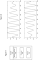
- FIG. 6 The motivation for this operation can be found by studying the effect of a time reversed window on a sinusoid as illustrated in Figure 6 .
- the upper plot shows the window applied in a first direction
- the lower plot shows the window applied in the reverse direction.
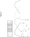
- the three coefficients representing the sinusoid is illustrated in Figure 7 , which illustrates how a reversed time window affect the DFT coefficients in the complex plane.
- the three DFT coefficients approximating the sinusoid in in the upper plot of Figure 6 is marked with circles, while the corresponding coefficients of the lower plot of Figure 6 is marked with stars.
- the diamond denotes the position of the original phase of the sinusoid and the dashed line shows an observed mirroring plane through which the coefficients of the time reversed window are projected.
- the time reversed window gives a mirroring of the coefficients in a mirroring plane with an angle ⁇ m .
- ⁇ m ⁇ 0 + ⁇ frac
- [ ⁇ ] denotes the rounding operation.
- ⁇ ⁇ expressed as a positive angle
- the angle ⁇ ⁇ is expressed as a function of the frequency f .
- ⁇ ⁇ ⁇ f frac ⁇ C where ⁇ C is a constant.
- modules may be stored in memory 904 of Figure 9 , and these modules may provide instructions so that when the instructions of a module are executed by respective decoder device processing circuitry 902, processing circuitry 902 performs respective operations of the flow chart.
- processing circuitry 902 generates frequency spectra on a subframe basis where consecutive subframes of the audio signal have a property that an applied window shape of first subframe of the consecutive subframes is a mirrored version or a time reversed version of a second subframe of the consecutive subframes.
- the processing circuitry 902 determines if a bad frame indicator (BFI) has been received.
- BFI bad frame indicator
- the decoder device 900 may proceed with preforming the frequency domain processing steps, performing the inverse DFT transform and reconstructing the output audio using an overlap-add strategy as described above and illustrated in Figure 4 . Note that the principle of overlap-add is the same for both subframes and frames. The creation of a frame requires applying overlap-add on the subframes, while the final output frame is the result of an overlap-add operation between frames.
- the processing circuitry 902 detects a bad frame through a bad frame indicator (BFI) in operation 1002, the PLC operations 1006 to 1030 are performed.
- BFI bad frame indicator
- the processing circuitry 902 obtains the signal spectrum corresponding to the second subframe of a first two consecutive subframes previously correctly decoded and processed.
- the processing circuitry 902 may obtain the signal spectrum from the memory 904 of the decoding device.
- the processing circuitry 902 detects peaks of the signal spectrum of a previously received audio frame of the audio signal on a fractional frequency scale, the previously received audio frame received prior to receiving the bad frame indicator.
- the processing circuitry 902 determines whether the concealment frame is for the first subframe of two consecutive subframes.
- the tuning constant ⁇ C may be a value in a range between 0.1 and 0.7.
- the processing circuitry 902 derives a time reversed phase correction to apply to the peaks of the signal spectrum based on the estimated phase.
- the processing circuitry 902 applies the time reversed phase correction to the peaks of the signal spectrum to form time reversed phase corrected peaks.
- the processing circuitry 902 applies a time reversal to the concealment audio subframe.
- the time reversal may be applied by applying a complex conjugate to the concealment audio subframe.
- the processing circuitry 902 combines the time reversed phase corrected peaks with a noise spectrum of the signal spectrum to form a combined spectrum of the concealment audio subframe.
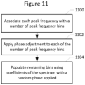
- 1016 and 1018 may be performed by the processing circuitry 902 associating each peak with a number of peak frequency bins in operation 1100.
- the processing circuitry 902 associating may apply the time reversed phase correction by applying the time reversed phase correction to each of the number of frequency bins in operation 1102.
- remaining bins are populated using coefficients of the signal spectrum with a random phase applied.
- the processing circuitry 902 generates a synthesized concealment audio subframe based on the combined spectrum
- the processing circuitry 902 derives in operation 1024 a non-time reversed phase correction to apply to the peaks of the signal spectrum for a second concealment subframe of the at least two consecutive concealment subframes.
- the processing circuitry 902 applies the non-time reversed phase correction to the peaks of the signal spectrum for the second subframe to form non-time reversed phase corrected peaks.
- the processing circuitry 902 combines the non-time reversed phase corrected peaks with a noise spectrum of the signal spectrum to form a combined spectrum for the second concealment subframe.
- the processing circuitry 902 generates a second synthesized concealment audio subframe based on the combined spectrum.
- 1026 and 1028 may be performed by the processing circuitry 902 associating each peak with a number of peak frequency bins in operation 1100.
- the processing circuitry 902 associating may apply the non-time reversed phase correction by applying the non-time reversed phase correction to each of the number of frequency bins in operation 1102.
- remaining bins are populated using coefficients of the signal spectrum with a random phase applied.
- Example embodiments are described herein with reference to block diagrams and/or flowchart illustrations of computer-implemented methods, apparatus (systems and/or devices) and/or computer program products. It is understood that a block of the block diagrams and/or flowchart illustrations, and combinations of blocks in the block diagrams and/or flowchart illustrations, can be implemented by computer program instructions that are performed by one or more computer circuits.
- These computer program instructions may be provided to a processor circuit of a general purpose computer circuit, special purpose computer circuit, and/or other programmable data processing circuit to produce a machine, such that the instructions, which execute via the processor of the computer and/or other programmable data processing apparatus, transform and control transistors, values stored in memory locations, and other hardware components within such circuitry to implement the functions/acts specified in the block diagrams and/or flowchart block or blocks, and thereby create means (functionality) and/or structure for implementing the functions/acts specified in the block diagrams and/or flowchart block(s).
Landscapes
- Engineering & Computer Science (AREA)
- Physics & Mathematics (AREA)
- Computational Linguistics (AREA)
- Signal Processing (AREA)
- Health & Medical Sciences (AREA)
- Audiology, Speech & Language Pathology (AREA)
- Human Computer Interaction (AREA)
- Acoustics & Sound (AREA)
- Multimedia (AREA)
- Spectroscopy & Molecular Physics (AREA)
- Compression, Expansion, Code Conversion, And Decoders (AREA)
- Transmission Systems Not Characterized By The Medium Used For Transmission (AREA)
Applications Claiming Priority (3)
| Application Number | Priority Date | Filing Date | Title |
|---|---|---|---|
| US201962860922P | 2019-06-13 | 2019-06-13 | |
| EP20728023.1A EP3984026B1 (de) | 2019-06-13 | 2020-05-25 | Fehlermaskierung zeitumgekehrter audiosubframes |
| PCT/EP2020/064394 WO2020249380A1 (en) | 2019-06-13 | 2020-05-25 | Time reversed audio subframe error concealment |
Related Parent Applications (1)
| Application Number | Title | Priority Date | Filing Date |
|---|---|---|---|
| EP20728023.1A Division EP3984026B1 (de) | 2019-06-13 | 2020-05-25 | Fehlermaskierung zeitumgekehrter audiosubframes |
Publications (2)
| Publication Number | Publication Date |
|---|---|
| EP4560625A2 true EP4560625A2 (de) | 2025-05-28 |
| EP4560625A3 EP4560625A3 (de) | 2025-06-25 |
Family
ID=70847403
Family Applications (2)
| Application Number | Title | Priority Date | Filing Date |
|---|---|---|---|
| EP20728023.1A Active EP3984026B1 (de) | 2019-06-13 | 2020-05-25 | Fehlermaskierung zeitumgekehrter audiosubframes |
| EP25162237.9A Pending EP4560625A3 (de) | 2019-06-13 | 2020-05-25 | Zeitumkehr-ecu-synthese |
Family Applications Before (1)
| Application Number | Title | Priority Date | Filing Date |
|---|---|---|---|
| EP20728023.1A Active EP3984026B1 (de) | 2019-06-13 | 2020-05-25 | Fehlermaskierung zeitumgekehrter audiosubframes |
Country Status (8)
| Country | Link |
|---|---|
| US (3) | US11967327B2 (de) |
| EP (2) | EP3984026B1 (de) |
| JP (2) | JP7371133B2 (de) |
| CN (2) | CN113950719B (de) |
| BR (1) | BR112021021928A2 (de) |
| CO (1) | CO2021016704A2 (de) |
| ES (1) | ES3017157T3 (de) |
| WO (1) | WO2020249380A1 (de) |
Families Citing this family (2)
| Publication number | Priority date | Publication date | Assignee | Title |
|---|---|---|---|---|
| WO2020249380A1 (en) * | 2019-06-13 | 2020-12-17 | Telefonaktiebolaget Lm Ericsson (Publ) | Time reversed audio subframe error concealment |
| DE102021128434A1 (de) * | 2021-11-02 | 2023-05-04 | Knorr-Bremse Systeme für Nutzfahrzeuge GmbH | Verfahren und Vorrichtung zum Betreiben einer gesicherten Datenkommunikation zwischen Funktionseinheiten für ein Fahrzeug |
Family Cites Families (21)
| Publication number | Priority date | Publication date | Assignee | Title |
|---|---|---|---|---|
| KR101203348B1 (ko) | 2005-01-31 | 2012-11-20 | 스카이프 | 가중 오버랩 애드 방법 |
| US8346546B2 (en) * | 2006-08-15 | 2013-01-01 | Broadcom Corporation | Packet loss concealment based on forced waveform alignment after packet loss |
| CN107103910B (zh) * | 2011-10-21 | 2020-09-18 | 三星电子株式会社 | 帧错误隐藏方法和设备以及音频解码方法和设备 |
| CN102833037B (zh) * | 2012-07-18 | 2015-04-29 | 华为技术有限公司 | 一种语音数据丢包的补偿方法及装置 |
| US9129600B2 (en) * | 2012-09-26 | 2015-09-08 | Google Technology Holdings LLC | Method and apparatus for encoding an audio signal |
| WO2014108738A1 (en) * | 2013-01-08 | 2014-07-17 | Nokia Corporation | Audio signal multi-channel parameter encoder |
| FR3001593A1 (fr) * | 2013-01-31 | 2014-08-01 | France Telecom | Correction perfectionnee de perte de trame au decodage d'un signal. |
| KR102110212B1 (ko) * | 2013-02-05 | 2020-05-13 | 텔레폰악티에볼라겟엘엠에릭슨(펍) | 오디오 프레임 손실 은폐를 제어하기 위한 방법 및 장치 |
| FR3004876A1 (fr) * | 2013-04-18 | 2014-10-24 | France Telecom | Correction de perte de trame par injection de bruit pondere. |
| PL3285254T3 (pl) * | 2013-10-31 | 2019-09-30 | Fraunhofer-Gesellschaft zur Förderung der angewandten Forschung e.V. | Dekoder audio i sposób dostarczania zdekodowanej informacji audio z wykorzystaniem ukrywania błędów na bazie sygnału wzbudzenia w dziedzinie czasu |
| CN111105807B (zh) * | 2014-01-15 | 2023-09-15 | 三星电子株式会社 | 对线性预测编码系数进行量化的加权函数确定装置和方法 |
| EP2922055A1 (de) | 2014-03-19 | 2015-09-23 | Fraunhofer-Gesellschaft zur Förderung der angewandten Forschung e.V. | Vorrichtung, Verfahren und zugehöriges Computerprogramm zur Erzeugung eines Fehlerverschleierungssignals mit einzelnen Ersatz-LPC-Repräsentationen für individuelle Codebuchinformationen |
| JP6490715B2 (ja) * | 2014-06-13 | 2019-03-27 | テレフオンアクチーボラゲット エルエム エリクソン(パブル) | フレーム喪失隠蔽のための方法、受信エンティティ、及びコンピュータプログラム |
| CN112216288B (zh) * | 2014-07-28 | 2024-07-05 | 三星电子株式会社 | 用于音频信号的时域数据包丢失隐藏的方法 |
| MX384925B (es) * | 2016-03-07 | 2025-03-11 | Fraunhofer Ges Forschung | Unidad de ocultamiento de error, decodificador de audio y método relacionado y programa de computadora que desaparece una trama de audio ocultada de acuerdo con factores de amortiguamiento diferentes para bandas de frecuencia diferentes. |
| CA3016837C (en) * | 2016-03-07 | 2021-09-28 | Fraunhofer-Gesellschaft Zur Foerderung Der Angewandten Forschung E.V. | Hybrid concealment method: combination of frequency and time domain packet loss concealment in audio codecs |
| JP6652469B2 (ja) * | 2016-09-07 | 2020-02-26 | 日本電信電話株式会社 | 復号装置、復号方法及びプログラム |
| CN110114988B (zh) * | 2016-11-10 | 2021-09-07 | 松下电器(美国)知识产权公司 | 发送方法、发送装置及记录介质 |
| US10714098B2 (en) * | 2017-12-21 | 2020-07-14 | Dolby Laboratories Licensing Corporation | Selective forward error correction for spatial audio codecs |
| EP3553777B1 (de) * | 2018-04-09 | 2022-07-20 | Dolby Laboratories Licensing Corporation | Verdecken von paketverlusten mit niedriger komplexität für transcodierte audiosignale |
| WO2020249380A1 (en) * | 2019-06-13 | 2020-12-17 | Telefonaktiebolaget Lm Ericsson (Publ) | Time reversed audio subframe error concealment |
-
2020
- 2020-05-25 WO PCT/EP2020/064394 patent/WO2020249380A1/en not_active Ceased
- 2020-05-25 EP EP20728023.1A patent/EP3984026B1/de active Active
- 2020-05-25 JP JP2021573331A patent/JP7371133B2/ja active Active
- 2020-05-25 EP EP25162237.9A patent/EP4560625A3/de active Pending
- 2020-05-25 ES ES20728023T patent/ES3017157T3/es active Active
- 2020-05-25 BR BR112021021928A patent/BR112021021928A2/pt unknown
- 2020-05-25 CN CN202080042683.0A patent/CN113950719B/zh active Active
- 2020-05-25 CN CN202510545723.8A patent/CN120148527A/zh active Pending
- 2020-06-04 US US17/618,676 patent/US11967327B2/en active Active
-
2021
- 2021-12-09 CO CONC2021/0016704A patent/CO2021016704A2/es unknown
-
2023
- 2023-10-18 JP JP2023179369A patent/JP7789733B2/ja active Active
-
2024
- 2024-03-18 US US18/608,303 patent/US12293766B2/en active Active
-
2025
- 2025-04-07 US US19/171,555 patent/US20250232779A1/en active Pending
Non-Patent Citations (4)
| Title |
|---|
| "Codec for Enhanced Voice Services (EVS); Error Concealment of Lost Packets (Release 12", 3GPP TS 26.447 |
| J. LECOMTE ET AL.: "Packet-loss concealment technology advances in EVS", 2015 IEEE INTERNATIONAL CONFERENCE ON ACOUSTICS, SPEECH AND SIGNAL PROCESSING (ICASSP, 2015, pages 5708 - 5712, XP055228507, DOI: 10.1109/ICASSP.2015.7179065 |
| S. BRUHN, E. NORVELL, J. SVEDBERG AND S. SVERRISSON: "A novel sinusoidal approach to audio signal frame loss concealment and its application in the new evs codec standard", 2015 IEEE INTERNATIONAL CONFERENCE ON ACOUSTICS, SPEECH AND SIGNAL PROCESSING (ICASSP, 2015, pages 5142 - 5146, XP033187741, DOI: 10.1109/ICASSP.2015.7178951 |
| T. VAILLANCOURT, M. JELINEK, R. SALAMI AND R. LEFEBVRE: "Efficient Frame Erasure Concealment in Predictive Speech Codecs using Glottal Pulse Resynchronisation", 2007 IEEE INTERNATIONAL CONFERENCE ON ACOUSTICS, 2007, pages IV1113 - IV1116 |
Also Published As
| Publication number | Publication date |
|---|---|
| EP3984026A1 (de) | 2022-04-20 |
| US20220246156A1 (en) | 2022-08-04 |
| CN113950719A (zh) | 2022-01-18 |
| EP3984026C0 (de) | 2025-03-12 |
| WO2020249380A1 (en) | 2020-12-17 |
| CN113950719B (zh) | 2025-05-02 |
| ES3017157T3 (en) | 2025-05-12 |
| JP7371133B2 (ja) | 2023-10-30 |
| US20240221760A1 (en) | 2024-07-04 |
| JP2022536158A (ja) | 2022-08-12 |
| EP3984026B1 (de) | 2025-03-12 |
| CO2021016704A2 (es) | 2022-01-17 |
| JP2024012337A (ja) | 2024-01-30 |
| EP4560625A3 (de) | 2025-06-25 |
| JP7789733B2 (ja) | 2025-12-22 |
| US12293766B2 (en) | 2025-05-06 |
| BR112021021928A2 (pt) | 2021-12-21 |
| US20250232779A1 (en) | 2025-07-17 |
| US11967327B2 (en) | 2024-04-23 |
| CN120148527A (zh) | 2025-06-13 |
Similar Documents
| Publication | Publication Date | Title |
|---|---|---|
| US20250232779A1 (en) | Time reversed audio subframe error concealment | |
| CN101325631B (zh) | 一种估计基音周期的方法和装置 | |
| US20240274135A1 (en) | Method and apparatus for controlling multichannel audio frame loss concealment | |
| US12340812B2 (en) | Methods for phase ECU F0 interpolation split and related controller | |
| EP2901446A1 (de) | Positionsabhängige hybrid-domain-paketverlustmaskierung | |
| US10224041B2 (en) | Apparatus, method and corresponding computer program for generating an error concealment signal using power compensation | |
| US10614818B2 (en) | Apparatus and method for generating an error concealment signal using individual replacement LPC representations for individual codebook information | |
| JP2026053413A (ja) | 時間反転されたオーディオサブフレームエラー隠蔽 |
Legal Events
| Date | Code | Title | Description |
|---|---|---|---|
| PUAI | Public reference made under article 153(3) epc to a published international application that has entered the european phase |
Free format text: ORIGINAL CODE: 0009012 |
|
| STAA | Information on the status of an ep patent application or granted ep patent |
Free format text: STATUS: THE APPLICATION HAS BEEN PUBLISHED |
|
| REG | Reference to a national code |
Ref country code: DE Ref legal event code: R079 Free format text: PREVIOUS MAIN CLASS: G10L0019022000 Ipc: G10L0019005000 |
|
| PUAL | Search report despatched |
Free format text: ORIGINAL CODE: 0009013 |
|
| AC | Divisional application: reference to earlier application |
Ref document number: 3984026 Country of ref document: EP Kind code of ref document: P |
|
| AK | Designated contracting states |
Kind code of ref document: A2 Designated state(s): AL AT BE BG CH CY CZ DE DK EE ES FI FR GB GR HR HU IE IS IT LI LT LU LV MC MK MT NL NO PL PT RO RS SE SI SK SM TR |
|
| AK | Designated contracting states |
Kind code of ref document: A3 Designated state(s): AL AT BE BG CH CY CZ DE DK EE ES FI FR GB GR HR HU IE IS IT LI LT LU LV MC MK MT NL NO PL PT RO RS SE SI SK SM TR |
|
| RIC1 | Information provided on ipc code assigned before grant |
Ipc: G10L 19/022 20130101ALN20250522BHEP Ipc: G10L 19/005 20130101AFI20250522BHEP |
|
| STAA | Information on the status of an ep patent application or granted ep patent |
Free format text: STATUS: REQUEST FOR EXAMINATION WAS MADE |
|
| 17P | Request for examination filed |
Effective date: 20251105 |
|
| STAA | Information on the status of an ep patent application or granted ep patent |
Free format text: STATUS: EXAMINATION IS IN PROGRESS |
|
| 17Q | First examination report despatched |
Effective date: 20251222 |