EP4560576A1 - System and method for calibrating camera - Google Patents
System and method for calibrating camera Download PDFInfo
- Publication number
- EP4560576A1 EP4560576A1 EP24170805.6A EP24170805A EP4560576A1 EP 4560576 A1 EP4560576 A1 EP 4560576A1 EP 24170805 A EP24170805 A EP 24170805A EP 4560576 A1 EP4560576 A1 EP 4560576A1
- Authority
- EP
- European Patent Office
- Prior art keywords
- camera
- calibration
- calibration chart
- image
- parameter
- Prior art date
- Legal status (The legal status is an assumption and is not a legal conclusion. Google has not performed a legal analysis and makes no representation as to the accuracy of the status listed.)
- Granted
Links
Images



Classifications
-
- G—PHYSICS
- G06—COMPUTING OR CALCULATING; COUNTING
- G06T—IMAGE DATA PROCESSING OR GENERATION, IN GENERAL
- G06T7/00—Image analysis
- G06T7/80—Analysis of captured images to determine intrinsic or extrinsic camera parameters, i.e. camera calibration
-
- H—ELECTRICITY
- H04—ELECTRIC COMMUNICATION TECHNIQUE
- H04N—PICTORIAL COMMUNICATION, e.g. TELEVISION
- H04N23/00—Cameras or camera modules comprising electronic image sensors; Control thereof
- H04N23/60—Control of cameras or camera modules
- H04N23/63—Control of cameras or camera modules by using electronic viewfinders
- H04N23/631—Graphical user interfaces [GUI] specially adapted for controlling image capture or setting capture parameters
- H04N23/632—Graphical user interfaces [GUI] specially adapted for controlling image capture or setting capture parameters for displaying or modifying preview images prior to image capturing, e.g. variety of image resolutions or capturing parameters
-
- G—PHYSICS
- G06—COMPUTING OR CALCULATING; COUNTING
- G06V—IMAGE OR VIDEO RECOGNITION OR UNDERSTANDING
- G06V20/00—Scenes; Scene-specific elements
- G06V20/50—Context or environment of the image
-
- H—ELECTRICITY
- H04—ELECTRIC COMMUNICATION TECHNIQUE
- H04N—PICTORIAL COMMUNICATION, e.g. TELEVISION
- H04N23/00—Cameras or camera modules comprising electronic image sensors; Control thereof
- H04N23/60—Control of cameras or camera modules
- H04N23/62—Control of parameters via user interfaces
-
- H—ELECTRICITY
- H04—ELECTRIC COMMUNICATION TECHNIQUE
- H04N—PICTORIAL COMMUNICATION, e.g. TELEVISION
- H04N23/00—Cameras or camera modules comprising electronic image sensors; Control thereof
- H04N23/60—Control of cameras or camera modules
- H04N23/64—Computer-aided capture of images, e.g. transfer from script file into camera, check of taken image quality, advice or proposal for image composition or decision on when to take image
-
- G—PHYSICS
- G06—COMPUTING OR CALCULATING; COUNTING
- G06T—IMAGE DATA PROCESSING OR GENERATION, IN GENERAL
- G06T2207/00—Indexing scheme for image analysis or image enhancement
- G06T2207/10—Image acquisition modality
- G06T2207/10024—Color image
-
- G—PHYSICS
- G06—COMPUTING OR CALCULATING; COUNTING
- G06T—IMAGE DATA PROCESSING OR GENERATION, IN GENERAL
- G06T2207/00—Indexing scheme for image analysis or image enhancement
- G06T2207/30—Subject of image; Context of image processing
- G06T2207/30204—Marker
- G06T2207/30208—Marker matrix
-
- G—PHYSICS
- G06—COMPUTING OR CALCULATING; COUNTING
- G06T—IMAGE DATA PROCESSING OR GENERATION, IN GENERAL
- G06T2207/00—Indexing scheme for image analysis or image enhancement
- G06T2207/30—Subject of image; Context of image processing
- G06T2207/30244—Camera pose
-
- G—PHYSICS
- G06—COMPUTING OR CALCULATING; COUNTING
- G06T—IMAGE DATA PROCESSING OR GENERATION, IN GENERAL
- G06T7/00—Image analysis
- G06T7/0002—Inspection of images, e.g. flaw detection
Definitions
- the disclosure relates to computer vision technology, and particularly relates to a system and a method for calibrating a camera.
- Modern computer vision system implementation leverages camera (or camera array system) with wide field of view (FOV) to implement depth estimation and wide FOV, wherein the computer vision system relies on high precision intrinsic parameter and high precision extrinsic parameter of the camera.
- the intrinsic parameter and the extrinsic parameter can be calibrated by a known geometry (or physical dimension) calibration chart as ground truth.
- the intrinsic calibration needs to collect dataset (or chart images) fill whole camera FOV to estimate the coefficients include but not limited to principal point, distortion, and focal length of the camera, thus a camera for the intrinsic calibration needs to take a lot of pictures of a calibration chart in different view angles, as camera 10 shown in FIG. 1 , or a huge calibration chart is needed for the intrinsic calibration, as calibration chart 20 shown in FIG. 2 .
- the extrinsic calibration relies on sharing coordinate system among cameras.
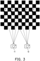
- the pictures taken by the two cameras have overlap at points B, C, and D of the flat calibration chart 20.
- the extrinsic parameter between camera 11 and camera 12 may be calibrated according to the observation of points B, C, D to estimate two poses of camera 11 and camera 12 in the coordinate system associated with the flat calibration chart 20.
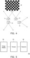
- the calibration of camera array having camera 11, 12, 13, and 14 cannot be implemented just by the flat calibration chart 20.
- the disclosure is directed to a system and a method for calibrating a camera.
- the present disclosure is directed to a system for calibrating a camera, including a storage medium storing information of a plurality of calibration charts and a processor coupled to the storage medium and the transceiver, wherein the processor is configured to: receive a plurality of images corresponding to the plurality of calibration charts; generate a virtual calibration chart according to the plurality of images and the information; receive a first image captured by a first camera, wherein the first image includes a first calibration chart of the plurality of calibration charts; and calibrate a first parameter of the first camera according to the first image and the virtual calibration chart.
- the processor is further configured to: generate the virtual calibration chart based on simultaneous localization and mapping algorithm.
- the processor is further configured to: detect a pattern on the first calibration chart in the first image to obtain an identity of the first calibration chart, wherein the identity is associated with the information; and calibrate the first parameter according to the identity.
- the first parameter includes an intrinsic parameter of the first camera.
- the processor is further configured to: receive a second image captured by a second camera, wherein the second camera includes a second calibration chart of the plurality of calibration chart; and calibrate the first parameter of the first camera and a second parameter of the second camera according to the first image, the second image, and the virtual calibration chart.
- the first parameter includes an intrinsic parameter of the first camera and an extrinsic parameter of the first camera.
- a first field of view of the first camera is not overlapped with a second field of view of the second camera.
- the first image further includes a second calibration chart of the plurality of calibration charts.
- the first calibration chart includes a black grid and a white grid.
- a first resolution of one of the plurality of images is greater than a second resolution of the first image.
- the present disclosure is directed to a method for calibrating a camera, including: receiving a plurality of images corresponding to a plurality of calibration charts; generate a virtual calibration chart according to the plurality of images and information of the plurality of calibration charts; receiving a first image captured by a first camera, wherein the first image includes a first calibration chart of the plurality of calibration charts; and calibrating a first parameter of the first camera according to the first image and the virtual calibration chart.
- FIG. 5 illustrates a schematic diagram of a system 100 for calibrating a camera according to an embodiment of the present disclosure.
- the system 100 may include a processor 110, a storage medium 120, and a transceiver 130.
- the processor 110 may be, for example, a central processing unit (CPU), or other programmable general purpose or special purpose micro control unit (MCU), a microprocessor, a digital signal processor (DSP), a programmable controller, an application specific integrated circuit (ASIC), a graphics unit (GPU), an arithmetic logic unit (ALU), a complex programmable logic device (CPLD), a field programmable gate array (FPGA), or other similar device or a combination of the above devices.
- the processor 110 may be coupled to the storage medium 120 and the transceiver 130.
- the storage medium 120 may be, for example, any type of fixed or removable random access memory (RAM), a read-only memory (ROM), a flash memory, a hard disk drive (HDD), a solid state drive (SSD) or similar element, or a combination thereof.
- the storage medium 120 may be a non-transitory computer readable storage medium configured to record a plurality of executable computer programs, modules, or applications to be loaded by the processor 110 to perform the function of the system 100.
- the transceiver 130 may be configured to transmit or receive wired/wireless signals.
- the transceiver 130 may also perform operations such as low noise amplifying, impedance matching, frequency mixing, up or down frequency conversion, filtering, amplifying, and so forth.
- the processor 110 may communicate with other devices (e.g., a camera or a camera array) via the transceiver 130.
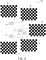
- FIG. 6 illustrates a schematic diagram of generating a virtual calibration chart according to an embodiment of the present disclosure.
- a plurality of calibration charts 60 may be spread in a calibration space 200.
- the camera 70 for generating the virtual calibration chart may capture a plurality of images corresponding to the plurality of calibration charts 60 in high resolution. Each of the images may include at least a part of one or more calibration charts 60. In one embodiment, a distance between calibration charts 60 may be less than the FOV of the camera 70 such that one or more images captured by the camera 70 may include more than one calibration chart 60.
- a pattern may be disposed on each calibration chart 60, wherein the pattern may include one or more black grids or white grids. The pattern on each calibration chart 60 may include information of the calibration chart 60 such as the identity of the calibration chart 60.
- the system may receive the plurality of images captured by the camera 70 through the transceiver 130.
- the plurality of images and the information of the plurality of calibration charts 60 may be stored in the storage medium 120 of the system 100.
- the processor 110 may detect a pattern on a calibration chart 60 in an image and obtain the identity of the calibration chart 60 according to the detection result.
- the information of the plurality of calibration charts 60 may be received by the system 100 through the transceiver 130.
- the processor 110 may generate a virtual calibration chart (e.g., virtual calibration chart 80 as shown in FIG. 7 ) corresponding to the calibration space 200 according to the plurality of images and the information of the plurality of calibration charts 60, wherein the generated virtual calibration chart 80 may include information such as information of each calibration chart 60, a relative position of two calibration charts 60, or the interpolation of the plurality of calibration charts 60.
- the processor 110 may generate the virtual calibration chart 80 based on simultaneous localization and mapping (SLAM) algorithm.
- SLAM simultaneous localization and mapping
- FIG. 7 illustrates a schematic diagram of calibrating a camera or a camera array according to an embodiment of the present disclosure.
- the system 100 may calibrate one camera to be calibrated (e.g., cameras 81, 82, 83, or 84) according to the virtual calibration chart 80.
- the user may capture, by the camera 81, one or more images of the virtual calibration chart 80 in the calibration space 200.
- the resolution of the camera to be calibrated e.g., cameras 81, 82, 83, or 84
- the system 100 may receive one or more images captured by the camera 81, wherein at least one image may include at least a part of one or more calibration charts 60, wherein the multiple calibration charts 60 may be the same as or different from each other.
- the processor 110 may detect the pattern on the calibration chart 60 in the image captured by the camera 81, so as to obtain information of the calibration chart 60 included in the image such as the identity of the calibration chart 60.
- the processor 110 may calibrate intrinsic parameters of the camera 81 according to the image captured by the camera 81 and the virtual calibration chart 80 stored in the storage medium 120, wherein the image captured by the camera 81 may include information of one or more calibration charts 60 such as an identity of a calibration chart 60 included in the captured image.
- the intrinsic parameters of camera 81 calibrated by the processor 110 may include, for example, a focal length, an optical principal point, or distortion of the camera 81.
- the system 100 may calibrate a plurality of cameras or a camera array in the same time according to the virtual calibration chart 80.
- the user may capture, by the camera 82, one or more images of the virtual calibration chart 80 in the calibration space 200, and the user may capture, by the camera 83, one or more images of the virtual chart 80 in the calibration space 200.
- the system 100 may receive one or more images captured by the camera 82 and one or more images captured by the camera 83, wherein at least one image captured by the camera 82 (and camera 83) may include at least a part of one or more calibration charts 60.
- the calibration chart 60 captured by the camera 82 may be the same as or different from the calibration chart 60 captured by the camera 83.
- the FOVs of the cameras to be calibrated may be overlapped (e.g., FOVs of camera 81 and 82) or not overlapped (e.g., FOVs of camera 82 and 83) with each other.
- the processor 110 may calibrate intrinsic parameters or extrinsic parameters of the camera 82 and camera 83 according to the image captured by the camera 81, the image captured by the camera 82 and camera 83, and the virtual calibration chart 80, wherein the image captured by the camera 82 (or camera 83) may include information of one or more calibration charts 60 such as an identity of a calibration chart 60 included in the captured image.
- the intrinsic parameters of camera 82 (or camera 83) calibrated by the processor 110 may include, for example, a focal length, an optical principal point, or distortion of the camera 82 (or camera 83).
- the extrinsic parameters of cameras 82 and 83 calibrated by the processor 110 may include, for example, a relative position between camera 82 and camera 83 or the coordinate system of camera 82 and camera 83.
- FIG. 8 illustrates a flowchart of a method for calibrating a camera according to an embodiment of the present disclosure, wherein the method may be implemented by the system 100 as shown in FIG. 5 .
- step S801 receiving a plurality of images corresponding to a plurality of calibration charts.
- step S802 generate a virtual calibration chart according to the plurality of images and information of the plurality of calibration charts.
- step S803 receiving a first image captured by a first camera, wherein the first image comprises a first calibration chart of the plurality of calibration charts.
- the system of the present disclosure may stitch multiple calibration charts distributed in a specific space into a virtual calibration chart as calibration ground truth.
- the user may take a picture of the virtual calibration chart by the camera (or camera array) to be calibrated.
- the system may calibrate the intrinsic parameters or extrinsic parameters of the camera (or camera array) according to the picture of the virtual calibration chart. Accordingly, the user of the camera with wide FOV may not need to prepare a huge calibration chart or may not need to take a lot of pictures of a calibration chart for calibrating the camera.
- calibration charts with any shapes may be used for the calibration.
- the calibration of the camera may be performed without high precision computer numerical control (CNC) engineering or unibody mechanical engineering. That is, the present disclosure provides a convenient way for calibrating a camera or a camera array.
- CNC computer numerical control
Landscapes
- Engineering & Computer Science (AREA)
- Multimedia (AREA)
- Physics & Mathematics (AREA)
- General Physics & Mathematics (AREA)
- Theoretical Computer Science (AREA)
- Signal Processing (AREA)
- Computer Vision & Pattern Recognition (AREA)
- Human Computer Interaction (AREA)
- Studio Devices (AREA)
- Testing, Inspecting, Measuring Of Stereoscopic Televisions And Televisions (AREA)
Abstract
Description
- The disclosure relates to computer vision technology, and particularly relates to a system and a method for calibrating a camera.
- Modern computer vision system implementation leverages camera (or camera array system) with wide field of view (FOV) to implement depth estimation and wide FOV, wherein the computer vision system relies on high precision intrinsic parameter and high precision extrinsic parameter of the camera. The intrinsic parameter and the extrinsic parameter can be calibrated by a known geometry (or physical dimension) calibration chart as ground truth.
- The intrinsic calibration needs to collect dataset (or chart images) fill whole camera FOV to estimate the coefficients include but not limited to principal point, distortion, and focal length of the camera, thus a camera for the intrinsic calibration needs to take a lot of pictures of a calibration chart in different view angles, as
camera 10 shown inFIG. 1 , or a huge calibration chart is needed for the intrinsic calibration, ascalibration chart 20 shown inFIG. 2 . - On the other hand, the extrinsic calibration relies on sharing coordinate system among cameras. In one embodiment shown in
FIG. 3 , whencamera 11 observes points A, B, C, and D andcamera 12 observes points B, C, D, and E of aflat calibration chart 20 , the pictures taken by the two cameras have overlap at points B, C, and D of theflat calibration chart 20. The extrinsic parameter betweencamera 11 andcamera 12 may be calibrated according to the observation of points B, C, D to estimate two poses ofcamera 11 andcamera 12 in the coordinate system associated with theflat calibration chart 20. However, for some wide FOV camera (or camera array), it is hard to retrieve overlap image by one flat calibration chart. As shown inFIG. 4 , the calibration of cameraarray having camera flat calibration chart 20. - The disclosure is directed to a system and a method for calibrating a camera.
- The present disclosure is directed to a system for calibrating a camera, including a storage medium storing information of a plurality of calibration charts and a processor coupled to the storage medium and the transceiver, wherein the processor is configured to: receive a plurality of images corresponding to the plurality of calibration charts; generate a virtual calibration chart according to the plurality of images and the information; receive a first image captured by a first camera, wherein the first image includes a first calibration chart of the plurality of calibration charts; and calibrate a first parameter of the first camera according to the first image and the virtual calibration chart.
- In one embodiment of the present disclosure, the processor is further configured to: generate the virtual calibration chart based on simultaneous localization and mapping algorithm.
- In one embodiment of the present disclosure, the processor is further configured to: detect a pattern on the first calibration chart in the first image to obtain an identity of the first calibration chart, wherein the identity is associated with the information; and calibrate the first parameter according to the identity.
- In one embodiment of the present disclosure, the first parameter includes an intrinsic parameter of the first camera.
- In one embodiment of the present disclosure, the processor is further configured to: receive a second image captured by a second camera, wherein the second camera includes a second calibration chart of the plurality of calibration chart; and calibrate the first parameter of the first camera and a second parameter of the second camera according to the first image, the second image, and the virtual calibration chart.
- In one embodiment of the present disclosure, the first parameter includes an intrinsic parameter of the first camera and an extrinsic parameter of the first camera.
- In one embodiment of the present disclosure, a first field of view of the first camera is not overlapped with a second field of view of the second camera.
- In one embodiment of the present disclosure, the first image further includes a second calibration chart of the plurality of calibration charts.
- In one embodiment of the present disclosure, the first calibration chart includes a black grid and a white grid.
- In one embodiment of the present disclosure, a first resolution of one of the plurality of images is greater than a second resolution of the first image.
- The present disclosure is directed to a method for calibrating a camera, including: receiving a plurality of images corresponding to a plurality of calibration charts; generate a virtual calibration chart according to the plurality of images and information of the plurality of calibration charts; receiving a first image captured by a first camera, wherein the first image includes a first calibration chart of the plurality of calibration charts; and calibrating a first parameter of the first camera according to the first image and the virtual calibration chart.
- To make the aforementioned more comprehensible, several embodiments accompanied with drawings are described in detail as follows.
- The accompanying drawings are included to provide a further understanding of the disclosure, and are incorporated in and constitute a part of this specification. The drawings illustrate exemplary embodiments of the disclosure and, together with the description, serve to explain the principles of the disclosure.
-
FIG. 1 illustrates a schematic diagram of taking pictures of a calibration chart. -
FIG. 2 illustrates a schematic diagram of a calibration chart with a huge size. -
FIG. 3 illustrates a schematic diagram of an extrinsic calibration for two cameras. -
FIG. 4 illustrates a schematic diagram of an extrinsic calibration for a camera array. -
FIG. 5 illustrates a schematic diagram of a system for calibrating a camera according to an embodiment of the present disclosure. -
FIG. 6 illustrates a schematic diagram of generating a virtual calibration chart according to an embodiment of the present disclosure. -
FIG. 7 illustrates a schematic diagram of calibrating a camera or a camera array according to an embodiment of the present disclosure. -
FIG. 8 illustrates a flowchart of a method for calibrating a camera according to an embodiment of the present disclosure. -
FIG. 5 illustrates a schematic diagram of asystem 100 for calibrating a camera according to an embodiment of the present disclosure. Thesystem 100 may include aprocessor 110, astorage medium 120, and atransceiver 130. Theprocessor 110 may be, for example, a central processing unit (CPU), or other programmable general purpose or special purpose micro control unit (MCU), a microprocessor, a digital signal processor (DSP), a programmable controller, an application specific integrated circuit (ASIC), a graphics unit (GPU), an arithmetic logic unit (ALU), a complex programmable logic device (CPLD), a field programmable gate array (FPGA), or other similar device or a combination of the above devices. Theprocessor 110 may be coupled to thestorage medium 120 and thetransceiver 130. - The
storage medium 120 may be, for example, any type of fixed or removable random access memory (RAM), a read-only memory (ROM), a flash memory, a hard disk drive (HDD), a solid state drive (SSD) or similar element, or a combination thereof. Thestorage medium 120 may be a non-transitory computer readable storage medium configured to record a plurality of executable computer programs, modules, or applications to be loaded by theprocessor 110 to perform the function of thesystem 100. - The
transceiver 130 may be configured to transmit or receive wired/wireless signals. Thetransceiver 130 may also perform operations such as low noise amplifying, impedance matching, frequency mixing, up or down frequency conversion, filtering, amplifying, and so forth. Theprocessor 110 may communicate with other devices (e.g., a camera or a camera array) via thetransceiver 130. -
FIG. 6 illustrates a schematic diagram of generating a virtual calibration chart according to an embodiment of the present disclosure. A plurality ofcalibration charts 60 may be spread in acalibration space 200. Thecamera 70 for generating the virtual calibration chart may capture a plurality of images corresponding to the plurality ofcalibration charts 60 in high resolution. Each of the images may include at least a part of one ormore calibration charts 60. In one embodiment, a distance betweencalibration charts 60 may be less than the FOV of thecamera 70 such that one or more images captured by thecamera 70 may include more than onecalibration chart 60. A pattern may be disposed on eachcalibration chart 60, wherein the pattern may include one or more black grids or white grids. The pattern on eachcalibration chart 60 may include information of thecalibration chart 60 such as the identity of thecalibration chart 60. The system may receive the plurality of images captured by thecamera 70 through thetransceiver 130. The plurality of images and the information of the plurality of calibration charts 60 (e.g., the location of thecalibration chart 60, the pattern or grids on thecalibration chart 60, the size of thecalibration chart 60, or the identity of the calibration chart 60) may be stored in thestorage medium 120 of thesystem 100. For example, theprocessor 110 may detect a pattern on acalibration chart 60 in an image and obtain the identity of thecalibration chart 60 according to the detection result. In one embodiment, the information of the plurality ofcalibration charts 60 may be received by thesystem 100 through thetransceiver 130. - The
processor 110 may generate a virtual calibration chart (e.g.,virtual calibration chart 80 as shown inFIG. 7 ) corresponding to thecalibration space 200 according to the plurality of images and the information of the plurality ofcalibration charts 60, wherein the generatedvirtual calibration chart 80 may include information such as information of eachcalibration chart 60, a relative position of twocalibration charts 60, or the interpolation of the plurality ofcalibration charts 60. In one embodiment, theprocessor 110 may generate thevirtual calibration chart 80 based on simultaneous localization and mapping (SLAM) algorithm. -
FIG. 7 illustrates a schematic diagram of calibrating a camera or a camera array according to an embodiment of the present disclosure. Thesystem 100 may calibrate one camera to be calibrated (e.g.,cameras virtual calibration chart 80. For example, the user may capture, by thecamera 81, one or more images of thevirtual calibration chart 80 in thecalibration space 200. The resolution of the camera to be calibrated (e.g.,cameras virtual calibration chart 80. - The
system 100 may receive one or more images captured by thecamera 81, wherein at least one image may include at least a part of one ormore calibration charts 60, wherein themultiple calibration charts 60 may be the same as or different from each other. Theprocessor 110 may detect the pattern on thecalibration chart 60 in the image captured by thecamera 81, so as to obtain information of thecalibration chart 60 included in the image such as the identity of thecalibration chart 60. After that, theprocessor 110 may calibrate intrinsic parameters of thecamera 81 according to the image captured by thecamera 81 and thevirtual calibration chart 80 stored in thestorage medium 120, wherein the image captured by thecamera 81 may include information of one ormore calibration charts 60 such as an identity of acalibration chart 60 included in the captured image. The intrinsic parameters ofcamera 81 calibrated by theprocessor 110 may include, for example, a focal length, an optical principal point, or distortion of thecamera 81. - The
system 100 may calibrate a plurality of cameras or a camera array in the same time according to thevirtual calibration chart 80. For example, the user may capture, by thecamera 82, one or more images of thevirtual calibration chart 80 in thecalibration space 200, and the user may capture, by thecamera 83, one or more images of thevirtual chart 80 in thecalibration space 200. Thesystem 100 may receive one or more images captured by thecamera 82 and one or more images captured by thecamera 83, wherein at least one image captured by the camera 82 (and camera 83) may include at least a part of one or more calibration charts 60. Thecalibration chart 60 captured by thecamera 82 may be the same as or different from thecalibration chart 60 captured by thecamera 83. In other words, the FOVs of the cameras to be calibrated may be overlapped (e.g., FOVs ofcamera 81 and 82) or not overlapped (e.g., FOVs ofcamera 82 and 83) with each other. - After that, the
processor 110 may calibrate intrinsic parameters or extrinsic parameters of thecamera 82 andcamera 83 according to the image captured by thecamera 81, the image captured by thecamera 82 andcamera 83, and thevirtual calibration chart 80, wherein the image captured by the camera 82 (or camera 83) may include information of one ormore calibration charts 60 such as an identity of acalibration chart 60 included in the captured image. The intrinsic parameters of camera 82 (or camera 83) calibrated by theprocessor 110 may include, for example, a focal length, an optical principal point, or distortion of the camera 82 (or camera 83). The extrinsic parameters ofcameras processor 110 may include, for example, a relative position betweencamera 82 andcamera 83 or the coordinate system ofcamera 82 andcamera 83. -
FIG. 8 illustrates a flowchart of a method for calibrating a camera according to an embodiment of the present disclosure, wherein the method may be implemented by thesystem 100 as shown inFIG. 5 . In step S801, receiving a plurality of images corresponding to a plurality of calibration charts. In step S802, generate a virtual calibration chart according to the plurality of images and information of the plurality of calibration charts. In step S803, receiving a first image captured by a first camera, wherein the first image comprises a first calibration chart of the plurality of calibration charts. In step S804, calibrating a first parameter of the first camera according to the first image and the virtual calibration chart. - In summary, the system of the present disclosure may stitch multiple calibration charts distributed in a specific space into a virtual calibration chart as calibration ground truth. After the virtual calibration chart being established, the user may take a picture of the virtual calibration chart by the camera (or camera array) to be calibrated. The system may calibrate the intrinsic parameters or extrinsic parameters of the camera (or camera array) according to the picture of the virtual calibration chart. Accordingly, the user of the camera with wide FOV may not need to prepare a huge calibration chart or may not need to take a lot of pictures of a calibration chart for calibrating the camera. Furthermore, calibration charts with any shapes may be used for the calibration. The calibration of the camera may be performed without high precision computer numerical control (CNC) engineering or unibody mechanical engineering. That is, the present disclosure provides a convenient way for calibrating a camera or a camera array.
- It will be apparent to those skilled in the art that various modifications and variations can be made to the disclosed embodiments without departing from the scope or spirit of the disclosure. In view of the foregoing, it is intended that the disclosure covers modifications and variations provided that they fall within the scope of the following claims and their equivalents.
Claims (11)
- A system for calibrating a camera, comprising:a storage medium, storing information of a plurality of calibration charts; anda processor, coupled to the storage medium and the transceiver, wherein the processor is configured to:receive a plurality of images corresponding to the plurality of calibration charts;generate a virtual calibration chart according to the plurality of images and the information;receive a first image captured by a first camera, wherein the first image comprises a first calibration chart of the plurality of calibration charts; andcalibrate a first parameter of the first camera according to the first image and the virtual calibration chart.
- The system of claim 1, wherein the processor is further configured to:
generate the virtual calibration chart based on simultaneous localization and mapping algorithm. - The system of claim 1, wherein the processor is further configured to:detect a pattern on the first calibration chart in the first image to obtain an identity of the first calibration chart, wherein the identity is associated with the information; andcalibrate the first parameter according to the identity.
- The system of claim 1, wherein the first parameter comprises an intrinsic parameter of the first camera.
- The system of claim 1, wherein the processor is further configured to:receive a second image captured by a second camera, wherein the second camera comprises a second calibration chart of the plurality of calibration chart; andcalibrate the first parameter of the first camera and a second parameter of the second camera according to the first image, the second image, and the virtual calibration chart.
- The system of claim 5, wherein the first parameter comprises an intrinsic parameter of the first camera and an extrinsic parameter of the first camera.
- The system of claim 5, wherein a first field of view of the first camera is not overlapped with a second field of view of the second camera.
- The system of claim 1, wherein the first image further comprises a second calibration chart of the plurality of calibration charts.
- The system of claim 1, wherein the first calibration chart comprises a black grid and a white grid.
- The system of claim 1, wherein a first resolution of one of the plurality of images is greater than a second resolution of the first image.
- A method for calibrating a camera, comprising:receiving a plurality of images corresponding to a plurality of calibration charts;generate a virtual calibration chart according to the plurality of images and information of the plurality of calibration charts;receiving a first image captured by a first camera, wherein the first image comprises a first calibration chart of the plurality of calibration charts; andcalibrating a first parameter of the first camera according to the first image and the virtual calibration chart.
Applications Claiming Priority (1)
| Application Number | Priority Date | Filing Date | Title |
|---|---|---|---|
| US18/518,631 US20250173899A1 (en) | 2023-11-24 | 2023-11-24 | System and method for calibrating camera |
Publications (3)
| Publication Number | Publication Date |
|---|---|
| EP4560576A1 true EP4560576A1 (en) | 2025-05-28 |
| EP4560576C0 EP4560576C0 (en) | 2026-03-25 |
| EP4560576B1 EP4560576B1 (en) | 2026-03-25 |
Family
ID=90789591
Family Applications (1)
| Application Number | Title | Priority Date | Filing Date |
|---|---|---|---|
| EP24170805.6A Active EP4560576B1 (en) | 2023-11-24 | 2024-04-17 | System and method for calibrating camera |
Country Status (4)
| Country | Link |
|---|---|
| US (1) | US20250173899A1 (en) |
| EP (1) | EP4560576B1 (en) |
| CN (1) | CN120050511A (en) |
| TW (1) | TWI882646B (en) |
Citations (1)
| Publication number | Priority date | Publication date | Assignee | Title |
|---|---|---|---|---|
| US20160012588A1 (en) * | 2014-07-14 | 2016-01-14 | Mitsubishi Electric Research Laboratories, Inc. | Method for Calibrating Cameras with Non-Overlapping Views |
Family Cites Families (25)
| Publication number | Priority date | Publication date | Assignee | Title |
|---|---|---|---|---|
| US8040361B2 (en) * | 2005-04-11 | 2011-10-18 | Systems Technology, Inc. | Systems and methods for combining virtual and real-time physical environments |
| US9519976B1 (en) * | 2011-01-28 | 2016-12-13 | Lucasfilm Entertainment Company Ltd. | Calibrating stereoscopic cameras |
| WO2012113732A1 (en) * | 2011-02-25 | 2012-08-30 | Fraunhofer-Gesellschaft Zur Foerderung Der Angewandten Forschung E.V. | Determining model parameters based on transforming a model of an object |
| US10176554B2 (en) * | 2015-10-05 | 2019-01-08 | Google Llc | Camera calibration using synthetic images |
| US10395389B2 (en) * | 2016-04-11 | 2019-08-27 | Hewlett-Packard Development Company, L.P. | Calibration based on intrinsic parameter selection and a projected calibration target |
| US10027954B2 (en) * | 2016-05-23 | 2018-07-17 | Microsoft Technology Licensing, Llc | Registering cameras in a multi-camera imager |
| WO2019049331A1 (en) * | 2017-09-08 | 2019-03-14 | 株式会社ソニー・インタラクティブエンタテインメント | Calibration device, calibration system, and calibration method |
| US10432912B2 (en) * | 2017-09-29 | 2019-10-01 | Waymo Llc | Target, method, and system for camera calibration |
| US11113887B2 (en) * | 2018-01-08 | 2021-09-07 | Verizon Patent And Licensing Inc | Generating three-dimensional content from two-dimensional images |
| EP3803776A4 (en) * | 2018-05-25 | 2022-03-23 | Packsize, LLC | Systems and methods for multi-camera placement |
| JP7227969B2 (en) * | 2018-05-30 | 2023-02-22 | パナソニック インテレクチュアル プロパティ コーポレーション オブ アメリカ | Three-dimensional reconstruction method and three-dimensional reconstruction apparatus |
| US10715705B2 (en) * | 2018-06-11 | 2020-07-14 | Pony Ai Inc. | Characterizing optical characteristics of optical elements |
| CN112385209B (en) * | 2018-07-17 | 2023-04-14 | 索尼公司 | Head-mounted display, control method of head-mounted display, information processing device, and display device |
| US11657535B2 (en) * | 2019-10-15 | 2023-05-23 | Nvidia Corporation | System and method for optimal camera calibration |
| TWI711010B (en) * | 2019-11-29 | 2020-11-21 | 財團法人成大研究發展基金會 | Geometric camera calibration system and method |
| IL271487B2 (en) * | 2019-12-17 | 2024-02-01 | BOROVSKY Igor | Dimensional calibration of the field-of-view of a single camera |
| US11156843B2 (en) * | 2020-01-10 | 2021-10-26 | Facebook Technologies, Llc | End-to-end artificial reality calibration testing |
| EP3905199A1 (en) * | 2020-05-01 | 2021-11-03 | Koninklijke Philips N.V. | Method of calibrating cameras |
| US11636622B2 (en) * | 2021-03-08 | 2023-04-25 | GM Cruise Holdings LLC. | Vehicle analysis environment with displays for vehicle sensor calibration and/or event simulation |
| US11908164B2 (en) * | 2021-07-23 | 2024-02-20 | Embark Trucks Inc. | Automatic extrinsic calibration using sensed data as a target |
| US11677931B2 (en) * | 2021-07-23 | 2023-06-13 | Embark Trucks Inc. | Automated real-time calibration |
| CN114419165B (en) * | 2022-01-17 | 2024-01-12 | 北京百度网讯科技有限公司 | Camera external parameter correction method, device, electronic equipment and storage medium |
| CN117474988A (en) * | 2022-07-22 | 2024-01-30 | 腾讯科技(深圳)有限公司 | A camera-based image acquisition method and related devices |
| CN115346054A (en) * | 2022-07-26 | 2022-11-15 | 重庆科技学院 | Cultural relic display augmented reality method based on visual SLAM |
| US20240046575A1 (en) * | 2022-08-05 | 2024-02-08 | Samsung Electronics Co., Ltd. | Video See-Through Augmented Reality |
-
2023
- 2023-11-24 US US18/518,631 patent/US20250173899A1/en not_active Abandoned
-
2024
- 2024-01-18 TW TW113102003A patent/TWI882646B/en active
- 2024-01-23 CN CN202410094634.1A patent/CN120050511A/en active Pending
- 2024-04-17 EP EP24170805.6A patent/EP4560576B1/en active Active
Patent Citations (1)
| Publication number | Priority date | Publication date | Assignee | Title |
|---|---|---|---|---|
| US20160012588A1 (en) * | 2014-07-14 | 2016-01-14 | Mitsubishi Electric Research Laboratories, Inc. | Method for Calibrating Cameras with Non-Overlapping Views |
Non-Patent Citations (1)
| Title |
|---|
| RAMEAU FRANCOIS ET AL: "MC-Calib: A generic and robust calibration toolbox for multi-camera systems", COMPUTER VISION AND IMAGE UNDERSTANDING, ACADEMIC PRESS, US, vol. 217, 12 January 2022 (2022-01-12), XP086988601, ISSN: 1077-3142, [retrieved on 20220112], DOI: 10.1016/J.CVIU.2021.103353 * |
Also Published As
| Publication number | Publication date |
|---|---|
| CN120050511A (en) | 2025-05-27 |
| EP4560576C0 (en) | 2026-03-25 |
| EP4560576B1 (en) | 2026-03-25 |
| TWI882646B (en) | 2025-05-01 |
| TW202522400A (en) | 2025-06-01 |
| US20250173899A1 (en) | 2025-05-29 |
Similar Documents
| Publication | Publication Date | Title |
|---|---|---|
| EP2453406B1 (en) | Ultrasonic image processing apparatus | |
| US10915998B2 (en) | Image processing method and device | |
| US11985294B2 (en) | Information processing apparatus, information processing method, and program | |
| CN112630750A (en) | Sensor calibration method and sensor calibration device | |
| CN110400342B (en) | Parameter adjustment method, device and electronic device for depth sensor | |
| JP6502511B2 (en) | Calculation device, control method of calculation device, and calculation program | |
| CN113160328A (en) | External reference calibration method, system, robot and storage medium | |
| US10708520B2 (en) | Calibration method of an image device and related image device and operational device thereof | |
| CN112907462B (en) | Ultra-wide-angle camera device distortion correction method, system and shooting device including the same | |
| JP2019091169A (en) | Image processing apparatus, control method for image processing apparatus, and program | |
| CN114463393A (en) | Image registration method, computer equipment and storage device | |
| CN114283177B (en) | Image registration method, device, electronic device and readable storage medium | |
| CN118552623A (en) | Positioning method, positioning device, terminal equipment and storage medium | |
| CN115830131B (en) | Method, device and equipment for determining fixed phase deviation | |
| CN120182337A (en) | A point cloud and image registration method and system | |
| JP2017011652A (en) | Image processing apparatus, imaging apparatus, image processing method, and program | |
| CN104915948B (en) | The system and method for selecting two-dimentional interest region for use scope sensor | |
| US20250173899A1 (en) | System and method for calibrating camera | |
| US10949988B2 (en) | Information processing apparatus, information processing method, and program | |
| CN109259793A (en) | Ultrasonic calibration system, method, electronic equipment and storage medium | |
| WO2019242394A1 (en) | Signal source space sensing method and apparatus, and active sensing system | |
| CN117392161B (en) | Calibration plate corner point for long-distance large perspective distortion and corner point number determination method | |
| US20230188692A1 (en) | Information processing apparatus using parallax in images captured from a plurality of directions, method and storage medium | |
| WO2021097807A1 (en) | Method and device for calibrating external parameters of detection device, and mobile platform | |
| JP6127399B2 (en) | Stereo camera device and program |
Legal Events
| Date | Code | Title | Description |
|---|---|---|---|
| STAA | Information on the status of an ep patent application or granted ep patent |
Free format text: STATUS: EXAMINATION IS IN PROGRESS |
|
| PUAI | Public reference made under article 153(3) epc to a published international application that has entered the european phase |
Free format text: ORIGINAL CODE: 0009012 |
|
| 17P | Request for examination filed |
Effective date: 20240417 |
|
| AK | Designated contracting states |
Kind code of ref document: A1 Designated state(s): AL AT BE BG CH CY CZ DE DK EE ES FI FR GB GR HR HU IE IS IT LI LT LU LV MC ME MK MT NL NO PL PT RO RS SE SI SK SM TR |
|
| GRAP | Despatch of communication of intention to grant a patent |
Free format text: ORIGINAL CODE: EPIDOSNIGR1 |
|
| STAA | Information on the status of an ep patent application or granted ep patent |
Free format text: STATUS: GRANT OF PATENT IS INTENDED |
|
| RIC1 | Information provided on ipc code assigned before grant |
Ipc: G06T 7/80 20170101AFI20251203BHEP Ipc: G06T 7/00 20170101ALN20251203BHEP |
|
| INTG | Intention to grant announced |
Effective date: 20251219 |
|
| GRAS | Grant fee paid |
Free format text: ORIGINAL CODE: EPIDOSNIGR3 |
|
| GRAA | (expected) grant |
Free format text: ORIGINAL CODE: 0009210 |
|
| STAA | Information on the status of an ep patent application or granted ep patent |
Free format text: STATUS: THE PATENT HAS BEEN GRANTED |
|
| AK | Designated contracting states |
Kind code of ref document: B1 Designated state(s): AL AT BE BG CH CY CZ DE DK EE ES FI FR GB GR HR HU IE IS IT LI LT LU LV MC ME MK MT NL NO PL PT RO RS SE SI SK SM TR |
|
| REG | Reference to a national code |
Ref country code: CH Ref legal event code: F10 Free format text: ST27 STATUS EVENT CODE: U-0-0-F10-F00 (AS PROVIDED BY THE NATIONAL OFFICE) Effective date: 20260325 Ref country code: GB Ref legal event code: FG4D |
|
| REG | Reference to a national code |
Ref country code: DE Ref legal event code: R096 Ref document number: 602024003351 Country of ref document: DE |
|
| REG | Reference to a national code |
Ref country code: IE Ref legal event code: FG4D |
|
| U01 | Request for unitary effect filed |
Effective date: 20260414 |
|
| U07 | Unitary effect registered |
Designated state(s): AT BE BG DE DK EE FI FR IT LT LU LV MT NL PT RO SE SI Effective date: 20260423 |
|
| U20 | Renewal fee for the european patent with unitary effect paid |
Year of fee payment: 3 Effective date: 20260429 |
|
| PG25 | Lapsed in a contracting state [announced via postgrant information from national office to epo] |
Ref country code: RS Free format text: LAPSE BECAUSE OF FAILURE TO SUBMIT A TRANSLATION OF THE DESCRIPTION OR TO PAY THE FEE WITHIN THE PRESCRIBED TIME-LIMIT Effective date: 20260625 |
|
| PG25 | Lapsed in a contracting state [announced via postgrant information from national office to epo] |
Ref country code: GR Free format text: LAPSE BECAUSE OF FAILURE TO SUBMIT A TRANSLATION OF THE DESCRIPTION OR TO PAY THE FEE WITHIN THE PRESCRIBED TIME-LIMIT Effective date: 20260626 |
|
| PG25 | Lapsed in a contracting state [announced via postgrant information from national office to epo] |
Ref country code: NO Free format text: LAPSE BECAUSE OF FAILURE TO SUBMIT A TRANSLATION OF THE DESCRIPTION OR TO PAY THE FEE WITHIN THE PRESCRIBED TIME-LIMIT Effective date: 20260625 |
|
| PG25 | Lapsed in a contracting state [announced via postgrant information from national office to epo] |
Ref country code: HR Free format text: LAPSE BECAUSE OF FAILURE TO SUBMIT A TRANSLATION OF THE DESCRIPTION OR TO PAY THE FEE WITHIN THE PRESCRIBED TIME-LIMIT Effective date: 20260325 |