EP4560415A1 - Safety protection system and test method - Google Patents
Safety protection system and test method Download PDFInfo
- Publication number
- EP4560415A1 EP4560415A1 EP22951964.0A EP22951964A EP4560415A1 EP 4560415 A1 EP4560415 A1 EP 4560415A1 EP 22951964 A EP22951964 A EP 22951964A EP 4560415 A1 EP4560415 A1 EP 4560415A1
- Authority
- EP
- European Patent Office
- Prior art keywords
- signal
- circuit
- safety protection
- output
- protection device
- Prior art date
- Legal status (The legal status is an assumption and is not a legal conclusion. Google has not performed a legal analysis and makes no representation as to the accuracy of the status listed.)
- Pending
Links
Images


Classifications
-
- G—PHYSICS
- G05—CONTROLLING; REGULATING
- G05B—CONTROL OR REGULATING SYSTEMS IN GENERAL; FUNCTIONAL ELEMENTS OF SUCH SYSTEMS; MONITORING OR TESTING ARRANGEMENTS FOR SUCH SYSTEMS OR ELEMENTS
- G05B9/00—Safety arrangements
- G05B9/02—Safety arrangements electric
- G05B9/03—Safety arrangements electric with multiple-channel loop, i.e. redundant control systems
-
- G—PHYSICS
- G21—NUCLEAR PHYSICS; NUCLEAR ENGINEERING
- G21D—NUCLEAR POWER PLANT
- G21D3/00—Control of nuclear power plant
- G21D3/04—Safety arrangements
Definitions
- the present disclosure relates to a safety protection system which outputs an operation request signal to plant equipment, for safety protection of a plant, and a test method therefor.
- the safety protection device In a case where abnormality has occurred in a nuclear power plant, the plant is controlled into a safe state by a safety protection device. Therefore, the safety protection device has a sufficiently multiplexed configuration so as to have high reliability. However, it is necessary to consider a case where the safety protection device does not normally operate when abnormality has occurred in the plant because of common factor failure between multiplexed devices due to software error or the like.
- a backup device to which equipment and a design different from those of the safety protection device are applied so as not to be influenced by common factor failure of the safety protection device, is provided.
- Patent Document 1 shows a safety protection system including a signal output circuit which receives output signals from both of a backup device and a safety protection device and outputs a predetermined safety-side operation signal when the output signals from the two devices do not coincide with each other.
- Patent Document 1 Japanese Patent No. 5675256
- devices composing a safety protection system of a nuclear power plant can be regularly confirmed about whether their functions have not been lost.
- a function implemented by software can be confirmed by a self-diagnosis function of a digital control device, but a function implemented by hardware needs to be confirmed by being actually operated.
- the signal output circuit disclosed in Patent Document 1 is a common circuit between the safety protection device and the backup device in the safety protection system, and has a circuit implemented by hardware. Therefore, in order to confirm that the function of the signal output circuit is sound, it is necessary to perform a total of three test operations for plant equipment, i.e., an operation by an operation request signal from a safety-protection-side device, an operation by an operation request signal from the backup device, and an operation for confirming a priority logic.
- the present disclosure has been made to solve the above problem, and an object of the present disclosure is to provide a safety protection system that makes it possible to test soundness of a signal output circuit which is a common circuit between a safety protection device and a backup device in the safety protection system while minimizing the number of times of operation of plant equipment.
- a safety protection system includes: a safety protection device which outputs an operation request signal to plant equipment, for safety protection of a plant; a backup device which backs up an output of the safety protection device when the safety protection device has failed; and a signal output circuit which unifies the output of the safety protection device and an output of the backup device, and outputs the operation request signal to the plant equipment so that the plant equipment operates to a safe side.
- Output signals that the backup device outputs are provided in a duplexed manner.
- the signal output circuit outputs the operation request signal only when both of the duplexed output signals of the backup device are ON, and circuit soundness is tested in a state in which the operation request signal to the plant equipment is blocked by the output signals each being turned ON one by one.
- the output signals from the backup device are duplexed, it becomes possible to test the output signal circuit in a state in which only one of the output signals from the backup device is turned ON so that the operation request signal to the plant equipment is blocked.
- the signal output circuit which is a common circuit between the safety protection device and the backup device in the safety protection system while minimizing the number of times of operation of plant equipment.
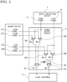
- FIG. 1 shows the entire configuration of a safety protection system according to embodiment 1 of the present disclosure.
- a safety protection system 1000 outputs a start signal and a stop signal as operation request signals to plant equipment needed for safely stopping the entire plant.
- a safety protection device 1 In a case where abnormality has occurred in the nuclear power plant, for leading the plant into a safe state, a safety protection device 1 outputs operation request signals such as a start signal 11 and a stop signal 12, to plant equipment 4 such as various pumps and valves for controlling processes for a flow rate, a pressure, a water level, and the like of a nuclear power plant system.
- the operation request signals outputted from the safety protection device 1 are transmitted through a signal output circuit 3 to the plant equipment 4. By operating the plant equipment 4, the plant is led into a safe state.
- the safety protection system 1000 is provided with a backup device 2 formed by hardware or the like.
- the backup device 2 outputs a first start signal 211 and a second start signal 212 for the plant equipment 4, and the outputted signals are transmitted through the signal output circuit 3 to the plant equipment 4.
- signals are digital signals indicating ON or OFF states, and are inputted as digital signals to an OR circuit, an AND circuit, and a NOT circuit which are logic circuits described later, and the logic circuits output digital signals of ON or OFF states.
- a case where a digital signal in an ON state is outputted may be described as an expression "a signal is outputted” or "a signal is transmitted”. When a signal is in an ON state, it may be described that "a signal is present", and when a signal is in an OFF state, it may be described that "a signal is absent”.
- the signal output circuit 3 includes a first OR circuit 301 which receives the first start signal 211 outputted from the backup device 2 and the start signal 11 outputted from the safety protection device 1, and a second OR circuit 302 which receives the second start signal 212 outputted from the backup device 2 and the start signal 11 outputted from the safety protection device 1.
- Output signals from the first OR circuit 301 and the second OR circuit 302 are inputted to a first AND circuit 311, and an output signal from the first AND circuit 311 is transmitted as a start signal to the plant equipment 4.
- the signal output circuit 3 includes a second AND circuit 312 which receives the stop signal 12 outputted from the safety protection device 1.
- the second AND circuit 312 receives an output signal from a NOT circuit 321 to which the output signal from the first AND circuit 311 is inputted. An output signal from the second AND circuit 312 is transmitted as a stop signal to the plant equipment 4.
- a start signal to the plant equipment 4 is ON, even if the stop signal 12 from the safety protection device 1 is ON, a stop signal is not transmitted to the plant equipment 4, and a start signal to the plant equipment 4 is prioritized.
- a circuit configuration is referred to as a priority circuit, and here, the priority circuit is a start signal prioritizing type.
- the signal output circuit 3 configured as described above, it is possible to start the plant equipment 4 from both of the safety protection device 1 and the backup device 2, and in a case where the safety protection device 1 and the backup device 2 transmit different operation request signals (one of them is a stop signal and the other is a start signal), the start signal can be preferentially transmitted to the plant equipment 4.
- the safety protection system 1000 includes the signal output circuit 3 which unifies operation request signals outputted from the safety protection device 1 and the backup device 2, and outputs the operation request signal to the plant equipment 4 so that the plant equipment 4 operates to a safe side, by the signal output circuit 3.
- the above signal output circuit 3 is formed by hardware such as a circuit of a relay or a discrete IC so as not to cause abnormality due to software error or the like. Therefore, in order to confirm that the function thereof is sound, a test is conducted regularly. Next, a test for confirming soundness of this circuit will be described.
- FIG. 2 is a flowchart showing a procedure of a test for confirming soundness of the signal output circuit 3 in embodiment 1.
- test input is performed by manual operation or a test device.
- the circuit configuration is provided so as to allow signal ON/OFF operation for the first start signal 211 and the second start signal 212 of the backup device and the start signal 11 and the stop signal 12 of the safety protection device 1.
- An output signal B1 from the first OR circuit 301, an output signal B2 from the second OR circuit 302, an output signal A1 from the first AND circuit 311, and an output signal A2 from the second AND circuit 312, which are output signals from the logic circuits of the signal output circuit 3, are detectable from outside, and a circuit for feeding back the output signals B1, B2 to the backup device 2 and the output signals A1, A2 to the safety protection device 1 is provided.
- step S1 the first start signal 211 and the second start signal 212 from the backup device 2 are each outputted one by one for a test, to confirm transmission to the signal output circuit 3.
- the first start signal 211 and the second start signal 212 are outputted at the same time.
- each signal is individually outputted.
- the output signal B1 from the first OR circuit 301 is fed back to the backup device 2, whereby it can be confirmed that the signal has been transmitted to the first AND circuit 311.
- step S2 the start signal 11 and the stop signal 12 from the safety protection device 1 are outputted for a test, to confirm the signal output circuit 3. Also, in this step, operation of the plant equipment 4 is confirmed. In addition, signal transmission from the safety protection device 1 to the signal output circuit 3, the function of the signal output circuit 3, and signal transmission from the signal output circuit 3 to the plant equipment 4, are confirmed.
- the start signal 11 is outputted from the safety protection device 1.
- the start signal 11 is inputted through the first OR circuit 301 and the second OR circuit 302 of the signal output circuit 3 to the first AND circuit 311. Since the output signals B1, B2 from both of the first OR circuit 301 and the second OR circuit 302 become ON, the first AND circuit 311 outputs a start signal to the plant equipment 4.
- the output signal A1 from the first AND circuit 311 is fed back to the safety protection device 1, whereby it can be confirmed that the signal has been transmitted to the plant equipment 4.
- step S1 soundness of the first OR circuit 301, the second OR circuit 302, and the first AND circuit 311 can be confirmed.
- the stop signal 12 is similarly outputted from the safety protection device 1.
- the stop signal 12 is inputted to the second AND circuit 312 of the signal output circuit 3. Since the output signal A1 from the first AND circuit 311 is OFF, an output signal from the NOT circuit 321 becomes ON and the second AND circuit 312 outputs a stop signal to the plant equipment 4.
- the output signal A2 from the second AND circuit 312 is fed back to the safety protection device 1, whereby it can be confirmed that the stop signal has been transmitted to the plant equipment 4.
- step S1 soundness of the second AND circuit 312 can be confirmed.
- step S3 the priority function for the start signal and the stop signal is tested.
- the start signal 11 and the stop signal 12 are outputted (turned ON) at the same time from the safety protection device 1.
- the output signals B1, B2 from all of the first OR circuit 301 and the second OR circuit 302 become ON, so that the output signal A1 from the first AND circuit 311 becomes ON, and the output signal A1 is fed back to the safety protection device 1.
- the output signal A1 from the first AND circuit 311 is ON, an output signal from the NOT circuit 321 becomes OFF and the state in which the output signal A2 from the second AND circuit 312 remains OFF is fed back to the safety protection device 1.
- start signal 11 is prioritized over the stop signal 12 from the safety protection device 1 by the NOT circuit 321 and the second AND circuit 312.
- soundness of the signal output circuit 3 of the safety protection system 1000 can be tested through three steps. Among these steps, a test in which the plant equipment 4 actually undergoes start and stop operation is performed only once in step S2. With the circuit configuration and the test method as described above, it becomes possible to test soundness of the signal output circuit 3 which is a common circuit between the safety protection device 1 and the backup device 2 in the safety protection system 1000 while minimizing the number of times of operation of the plant equipment 4.
- FIG. 3 shows the entirety of a safety protection system 1000 according to embodiment 2.
- the backup device 2 is configured to be able to back up not only the start signal 11 of the safety protection device 1 but also an output of the stop signal 12.
- stop signals from the backup device 2 are outputted as a first stop signal 221 and a second stop signal 222 in a duplexed manner.
- the signal output circuit 3 includes the first OR circuit 301 which receives the first start signal 211 outputted from the backup device 2 and the start signal 11 outputted from the safety protection device 1, and the second OR circuit 302 which receives the second start signal 212 outputted from the backup device 2 and the start signal 11 outputted from the safety protection device 1.
- the signal output circuit 3 includes a third OR circuit 303 which receives the first stop signal 221 outputted from the backup device 2 and the stop signal 12 outputted from the safety protection device 1, and a fourth OR circuit 304 which receives the second stop signal 222 outputted from the backup device 2 and the stop signal 12 outputted from the safety protection device 1.
- the output signals from the third OR circuit 303 and the fourth OR circuit 304 are inputted to the second AND circuit 312.
- the second AND circuit 312 receives, in addition to the signals from the third OR circuit 303 and the fourth OR circuit 304, an output signal from the NOT circuit 321 to which the output signal from the first AND circuit 311 is inputted, and an output signal from the second AND circuit 312 is transmitted as a stop signal to the plant equipment 4.
- the signal output circuit 3 configured as described above, it is possible to start or stop the plant equipment 4 from both of the safety protection device 1 and the backup device 2.
- the safety protection device 1 and the backup device 2 transmit different operation request signals (one of them is a stop signal and the other is a start signal)
- the start signal can be preferentially transmitted to the plant equipment 4.
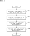
- FIG. 4 is a flowchart showing a procedure of the test for confirming soundness of the signal output circuit 3 in embodiment 2.
- test input is performed by manual operation or a test device.
- the circuit configuration is provided so as to allow signal ON/OFF operation for the first start signal 211, the second start signal 212, the first stop signal 221, and the second stop signal 222 of the backup device and the start signal 11 and the stop signal 12 of the safety protection device 1.
- the output signal B1 from the first OR circuit 301, the output signal B2 from the second OR circuit 302, an output signal B3 from the third OR circuit 303, an output signal B4 from the fourth OR circuit 304, the output signal A1 from the first AND circuit 311, and the output signal A2 from the second AND circuit 312, which are output signals from the logic circuits of the signal output circuit 3, are detectable from outside, and a circuit for feeding back the output signals B1, B2, B3, B4 to the backup device 2 and the output signals A1, A2 to the safety protection device 1 is provided.
- step S11 the first start signal 211 and the second start signal 212 from the backup device 2 are each outputted one by one for a test, to confirm transmission to the signal output circuit 3 (the same as in step S1).
- step S11 soundness of the first OR circuit 301 and the second OR circuit 302 can be confirmed.
- step S12 the first stop signal 221 and the second stop signal 222 from the backup device 2 are each outputted one by one for a test, to confirm transmission to the signal output circuit 3.
- each signal is individually outputted.
- the first stop signal 221 is outputted (turned ON), whereby the signal is inputted through the third OR circuit 303 to the second AND circuit 312.
- the output signal B3 from the third OR circuit 303 is fed back to the backup device 2, whereby it can be confirmed that the signal has been transmitted to the second AND circuit 312.
- step S13 the start signal 11 and the stop signal 12 from the safety protection device 1 are outputted for a test, to confirm the signal output circuit 3. Also, in this step, operation of the plant equipment 4 is confirmed. In addition, signal transmission from the safety protection device 1 to the signal output circuit 3, the function of the signal output circuit 3, and signal transmission from the signal output circuit 3 to the plant equipment 4, are confirmed (the same as in step S2). Through confirmation of the start signal 11, in combination with the test in step S11, soundness of the first OR circuit 301, the second OR circuit 302, and the first AND circuit 311 is confirmed.
- the stop signal 12 is outputted from the safety protection device 1.
- the stop signal 12 is inputted through the third OR circuit 303 and the fourth OR circuit 304 to the second AND circuit 312.
- the output signals B3, B4 from both of the third OR circuit 303 and the fourth OR circuit 304 become ON, and since the output signal from the first AND circuit 311 is OFF, the output signal from the NOT circuit 321 also becomes ON.
- the second AND circuit 312 outputs a stop signal to the plant equipment 4.
- the output signal A2 from the second AND circuit 312 is fed back to the safety protection device 1, whereby it can be confirmed that the signal has been outputted to the plant equipment 4.
- soundness of the third OR circuit 303, the fourth OR circuit 304, and the second AND circuit 312 can be confirmed.
- step S14 the priority function for the start signal and the stop signal is tested.
- the start signal 11 and the stop signal 12 are outputted (turned ON) at the same time from the safety protection device 1.
- the output signals B1, B2 from all of the first OR circuit 301 and the second OR circuit 302 become ON, so that the output signal A1 from the first AND circuit 311 becomes ON, and the output signal A1 is fed back to the safety protection device 1.
- output signals from the third OR circuit 303 and the fourth OR circuit 304 also become ON, but since the output signal A1 from the first AND circuit 311 is ON, an output signal from the NOT circuit 321 becomes OFF and the state in which the output signal A2 from the second AND circuit 312 remains OFF is fed back to the safety protection device 1.
- the start signal is prioritized by the NOT circuit 321 and the second AND circuit 312.
- soundness of the signal output circuit 3 of the safety protection system 1000 can be tested through four steps. Among these steps, a test in which the plant equipment 4 actually undergoes start and stop operation is performed only once in step S13. With the circuit configuration and the test method as described above, it becomes possible to test soundness of the signal output circuit 3 which is a common circuit between the safety protection device 1 and the backup device 2 in the safety protection system 1000 while minimizing the number of times of operation of the plant equipment 4.
- the backup device 2 can back up not only the start signal 11 of the safety protection device 1 but also the stop signal 12. That is, the safety protection system 1000 includes the signal output circuit 3 which unifies operation request signals for both of start and stop outputted from the safety protection device 1 and the backup device 2, and can output the operation request signal to the plant equipment 4 so that the plant equipment 4 operates to a safe side, by the signal output circuit 3.
Landscapes
- Physics & Mathematics (AREA)
- Engineering & Computer Science (AREA)
- Business, Economics & Management (AREA)
- Emergency Management (AREA)
- Plasma & Fusion (AREA)
- General Engineering & Computer Science (AREA)
- High Energy & Nuclear Physics (AREA)
- General Physics & Mathematics (AREA)
- Automation & Control Theory (AREA)
- Safety Devices In Control Systems (AREA)
- Monitoring And Testing Of Nuclear Reactors (AREA)
Abstract
Description
- The present disclosure relates to a safety protection system which outputs an operation request signal to plant equipment, for safety protection of a plant, and a test method therefor.
- In a case where abnormality has occurred in a nuclear power plant, the plant is controlled into a safe state by a safety protection device. Therefore, the safety protection device has a sufficiently multiplexed configuration so as to have high reliability. However, it is necessary to consider a case where the safety protection device does not normally operate when abnormality has occurred in the plant because of common factor failure between multiplexed devices due to software error or the like.
- In order to control the plant into a safe state in a case where common factor failure of the safety protection device is assumed, a backup device to which equipment and a design different from those of the safety protection device are applied so as not to be influenced by common factor failure of the safety protection device, is provided.
-
Patent Document 1 shows a safety protection system including a signal output circuit which receives output signals from both of a backup device and a safety protection device and outputs a predetermined safety-side operation signal when the output signals from the two devices do not coincide with each other. - Patent Document 1:
Japanese Patent No. 5675256 - It is required that devices composing a safety protection system of a nuclear power plant can be regularly confirmed about whether their functions have not been lost. A function implemented by software can be confirmed by a self-diagnosis function of a digital control device, but a function implemented by hardware needs to be confirmed by being actually operated.
- The signal output circuit disclosed in
Patent Document 1 is a common circuit between the safety protection device and the backup device in the safety protection system, and has a circuit implemented by hardware. Therefore, in order to confirm that the function of the signal output circuit is sound, it is necessary to perform a total of three test operations for plant equipment, i.e., an operation by an operation request signal from a safety-protection-side device, an operation by an operation request signal from the backup device, and an operation for confirming a priority logic. - The present disclosure has been made to solve the above problem, and an object of the present disclosure is to provide a safety protection system that makes it possible to test soundness of a signal output circuit which is a common circuit between a safety protection device and a backup device in the safety protection system while minimizing the number of times of operation of plant equipment.
- A safety protection system according to the present disclosure includes: a safety protection device which outputs an operation request signal to plant equipment, for safety protection of a plant; a backup device which backs up an output of the safety protection device when the safety protection device has failed; and a signal output circuit which unifies the output of the safety protection device and an output of the backup device, and outputs the operation request signal to the plant equipment so that the plant equipment operates to a safe side. Output signals that the backup device outputs are provided in a duplexed manner. The signal output circuit outputs the operation request signal only when both of the duplexed output signals of the backup device are ON, and circuit soundness is tested in a state in which the operation request signal to the plant equipment is blocked by the output signals each being turned ON one by one.
- According to the present disclosure, since the output signals from the backup device are duplexed, it becomes possible to test the output signal circuit in a state in which only one of the output signals from the backup device is turned ON so that the operation request signal to the plant equipment is blocked. Thus, it becomes possible to test soundness of the signal output circuit which is a common circuit between the safety protection device and the backup device in the safety protection system while minimizing the number of times of operation of plant equipment.
-
- [
FIG. 1] FIG. 1 shows the entire configuration of a safety protection system according toembodiment 1. - [
FIG. 2] FIG. 2 is a flowchart showing a test procedure for a signal output circuit in the safety protection system according toembodiment 1. - [
FIG. 3] FIG. 3 shows the entire configuration of a safety protection system according toembodiment 2. - [
FIG. 4] FIG. 4 is a flowchart showing a test procedure for a signal output circuit in the safety protection system according toembodiment 2. -
FIG. 1 shows the entire configuration of a safety protection system according toembodiment 1 of the present disclosure. In a case where abnormality has occurred in a nuclear power plant, a safety protection system 1000 outputs a start signal and a stop signal as operation request signals to plant equipment needed for safely stopping the entire plant. - In a case where abnormality has occurred in the nuclear power plant, for leading the plant into a safe state, a
safety protection device 1 outputs operation request signals such as astart signal 11 and astop signal 12, to plantequipment 4 such as various pumps and valves for controlling processes for a flow rate, a pressure, a water level, and the like of a nuclear power plant system. The operation request signals outputted from thesafety protection device 1 are transmitted through asignal output circuit 3 to theplant equipment 4. By operating theplant equipment 4, the plant is led into a safe state. - In preparation for a case where the
safety protection device 1 cannot perform output due to some failure such as software error when abnormality has occurred in the plant, the safety protection system 1000 is provided with abackup device 2 formed by hardware or the like. As with thesafety protection device 1, thebackup device 2 outputs afirst start signal 211 and asecond start signal 212 for theplant equipment 4, and the outputted signals are transmitted through thesignal output circuit 3 to theplant equipment 4. - These signals are digital signals indicating ON or OFF states, and are inputted as digital signals to an OR circuit, an AND circuit, and a NOT circuit which are logic circuits described later, and the logic circuits output digital signals of ON or OFF states. A case where a digital signal in an ON state is outputted may be described as an expression "a signal is outputted" or "a signal is transmitted". When a signal is in an ON state, it may be described that "a signal is present", and when a signal is in an OFF state, it may be described that "a signal is absent".
- The
signal output circuit 3 includes afirst OR circuit 301 which receives thefirst start signal 211 outputted from thebackup device 2 and thestart signal 11 outputted from thesafety protection device 1, and asecond OR circuit 302 which receives thesecond start signal 212 outputted from thebackup device 2 and thestart signal 11 outputted from thesafety protection device 1. - Output signals from the
first OR circuit 301 and thesecond OR circuit 302 are inputted to afirst AND circuit 311, and an output signal from thefirst AND circuit 311 is transmitted as a start signal to theplant equipment 4. - With this circuit configuration, when the
start signal 11 from thesafety protection device 1 is turned ON (signal is present), an output signal is transmitted as a start signal to theplant equipment 4. Even if thestart signal 11 from thesafety protection device 1 is OFF (signal is absent), when thefirst start signal 211 and thesecond start signal 212 which are start signals from thebackup device 2 are both ON, an output signal is transmitted as a start signal to theplant equipment 4. - Similarly, the
signal output circuit 3 includes a second ANDcircuit 312 which receives thestop signal 12 outputted from thesafety protection device 1. In addition, the second ANDcircuit 312 receives an output signal from aNOT circuit 321 to which the output signal from thefirst AND circuit 311 is inputted. An output signal from the second ANDcircuit 312 is transmitted as a stop signal to theplant equipment 4. - With this circuit configuration, when the start signal to the
plant equipment 4 is ON, even if thestop signal 12 from thesafety protection device 1 is ON, a stop signal is not transmitted to theplant equipment 4, and a start signal to theplant equipment 4 is prioritized. Such a circuit configuration is referred to as a priority circuit, and here, the priority circuit is a start signal prioritizing type. - With the
signal output circuit 3 configured as described above, it is possible to start theplant equipment 4 from both of thesafety protection device 1 and thebackup device 2, and in a case where thesafety protection device 1 and thebackup device 2 transmit different operation request signals (one of them is a stop signal and the other is a start signal), the start signal can be preferentially transmitted to theplant equipment 4. - That is, the safety protection system 1000 includes the
signal output circuit 3 which unifies operation request signals outputted from thesafety protection device 1 and thebackup device 2, and outputs the operation request signal to theplant equipment 4 so that theplant equipment 4 operates to a safe side, by thesignal output circuit 3. - The above
signal output circuit 3 is formed by hardware such as a circuit of a relay or a discrete IC so as not to cause abnormality due to software error or the like. Therefore, in order to confirm that the function thereof is sound, a test is conducted regularly. Next, a test for confirming soundness of this circuit will be described. -
FIG. 2 is a flowchart showing a procedure of a test for confirming soundness of thesignal output circuit 3 inembodiment 1. - Here, test input is performed by manual operation or a test device. The circuit configuration is provided so as to allow signal ON/OFF operation for the
first start signal 211 and thesecond start signal 212 of the backup device and thestart signal 11 and thestop signal 12 of thesafety protection device 1. - An output signal B1 from the
first OR circuit 301, an output signal B2 from thesecond OR circuit 302, an output signal A1 from thefirst AND circuit 311, and an output signal A2 from the second ANDcircuit 312, which are output signals from the logic circuits of thesignal output circuit 3, are detectable from outside, and a circuit for feeding back the output signals B1, B2 to thebackup device 2 and the output signals A1, A2 to thesafety protection device 1 is provided. - In
FIG. 2 , in step S1, thefirst start signal 211 and thesecond start signal 212 from thebackup device 2 are each outputted one by one for a test, to confirm transmission to thesignal output circuit 3. - In a case of starting the
plant equipment 4 from thebackup device 2, normally, thefirst start signal 211 and thesecond start signal 212 are outputted at the same time. In a case of testing thesignal output circuit 3, each signal is individually outputted. First, only thefirst start signal 211 is outputted (turned ON), whereby the signal is inputted through thefirst OR circuit 301 to thefirst AND circuit 311. At this time, since the output signal A1 from the first ANDcircuit 311 does not become ON, the plant equipment is not operated. The output signal B1 from thefirst OR circuit 301 is fed back to thebackup device 2, whereby it can be confirmed that the signal has been transmitted to thefirst AND circuit 311. - Similarly, only the
second start signal 212 is outputted (turned ON). This signal is inputted through thesecond OR circuit 302 to the first ANDcircuit 311. Since the output signal A1 from the first ANDcircuit 311 does not become ON, theplant equipment 4 is not operated. The output signal B2 from the second ORcircuit 302 is fed back to thebackup device 2, whereby it can be confirmed that the signal has been transmitted to the first ANDcircuit 311. - Next, in step S2, the
start signal 11 and thestop signal 12 from thesafety protection device 1 are outputted for a test, to confirm thesignal output circuit 3. Also, in this step, operation of theplant equipment 4 is confirmed. In addition, signal transmission from thesafety protection device 1 to thesignal output circuit 3, the function of thesignal output circuit 3, and signal transmission from thesignal output circuit 3 to theplant equipment 4, are confirmed. - First, the
start signal 11 is outputted from thesafety protection device 1. Thestart signal 11 is inputted through the first ORcircuit 301 and the second ORcircuit 302 of thesignal output circuit 3 to the first ANDcircuit 311. Since the output signals B1, B2 from both of the first ORcircuit 301 and the second ORcircuit 302 become ON, the first ANDcircuit 311 outputs a start signal to theplant equipment 4. The output signal A1 from the first ANDcircuit 311 is fed back to thesafety protection device 1, whereby it can be confirmed that the signal has been transmitted to theplant equipment 4. - Thus, in combination with the test in step S1, soundness of the first OR
circuit 301, the second ORcircuit 302, and the first ANDcircuit 311 can be confirmed. - Subsequently, the
stop signal 12 is similarly outputted from thesafety protection device 1. Thestop signal 12 is inputted to the second ANDcircuit 312 of thesignal output circuit 3. Since the output signal A1 from the first ANDcircuit 311 is OFF, an output signal from theNOT circuit 321 becomes ON and the second ANDcircuit 312 outputs a stop signal to theplant equipment 4. The output signal A2 from the second ANDcircuit 312 is fed back to thesafety protection device 1, whereby it can be confirmed that the stop signal has been transmitted to theplant equipment 4. - Thus, in combination with the test in step S1, soundness of the second AND
circuit 312 can be confirmed. - Lastly, in step S3, the priority function for the start signal and the stop signal is tested. The
start signal 11 and thestop signal 12 are outputted (turned ON) at the same time from thesafety protection device 1. As a result, the output signals B1, B2 from all of the first ORcircuit 301 and the second ORcircuit 302 become ON, so that the output signal A1 from the first ANDcircuit 311 becomes ON, and the output signal A1 is fed back to thesafety protection device 1. In addition, since the output signal A1 from the first ANDcircuit 311 is ON, an output signal from theNOT circuit 321 becomes OFF and the state in which the output signal A2 from the second ANDcircuit 312 remains OFF is fed back to thesafety protection device 1. - Thus, it can be confirmed that the
start signal 11 is prioritized over thestop signal 12 from thesafety protection device 1 by theNOT circuit 321 and the second ANDcircuit 312. - As described above, according to the present embodiment, soundness of the
signal output circuit 3 of the safety protection system 1000 can be tested through three steps. Among these steps, a test in which theplant equipment 4 actually undergoes start and stop operation is performed only once in step S2. With the circuit configuration and the test method as described above, it becomes possible to test soundness of thesignal output circuit 3 which is a common circuit between thesafety protection device 1 and thebackup device 2 in the safety protection system 1000 while minimizing the number of times of operation of theplant equipment 4. -
FIG. 3 shows the entirety of a safety protection system 1000 according toembodiment 2. In the safety protection system 1000 ofembodiment 2, thebackup device 2 is configured to be able to back up not only thestart signal 11 of thesafety protection device 1 but also an output of thestop signal 12. In addition, as with start signals, stop signals from thebackup device 2 are outputted as afirst stop signal 221 and asecond stop signal 222 in a duplexed manner. - The same components as those in
embodiment 1 are denoted by the same reference characters, and the detailed description thereof is omitted. - In
FIG. 3 , thesignal output circuit 3 includes the first ORcircuit 301 which receives thefirst start signal 211 outputted from thebackup device 2 and thestart signal 11 outputted from thesafety protection device 1, and the second ORcircuit 302 which receives the second start signal 212 outputted from thebackup device 2 and thestart signal 11 outputted from thesafety protection device 1. - Operations regarding the
start signal 11 from thesafety protection device 1 and thefirst start signal 211 and the second start signal 212 from thebackup device 2 therefor are the same as inembodiment 1 and therefore the description thereof is omitted. Next, operations regarding thestop signal 12 from thesafety protection device 1 and thefirst stop signal 221 and the second stop signal 222 from thebackup device 2 therefor will be described. - The
signal output circuit 3 includes a third ORcircuit 303 which receives thefirst stop signal 221 outputted from thebackup device 2 and thestop signal 12 outputted from thesafety protection device 1, and a fourth ORcircuit 304 which receives the second stop signal 222 outputted from thebackup device 2 and thestop signal 12 outputted from thesafety protection device 1. - The output signals from the third OR
circuit 303 and the fourth ORcircuit 304 are inputted to the second ANDcircuit 312. The second ANDcircuit 312 receives, in addition to the signals from the third ORcircuit 303 and the fourth ORcircuit 304, an output signal from theNOT circuit 321 to which the output signal from the first ANDcircuit 311 is inputted, and an output signal from the second ANDcircuit 312 is transmitted as a stop signal to theplant equipment 4. - With this circuit configuration, when the
stop signal 12 from thesafety protection device 1 is turned ON (signal is present), an output signal is transmitted as a stop signal to theplant equipment 4. Even if thestop signal 12 from thesafety protection device 1 is OFF (signal is absent), when thefirst stop signal 221 and the second stop signal 222 which are stop signals from thebackup device 2 are both ON, an output signal is transmitted as a stop signal to theplant equipment 4. - Also, with this circuit configuration, as in
embodiment 1, when the start signal to theplant equipment 4 is ON, even if thestop signal 12 from thesafety protection device 1 is ON, a stop signal is not transmitted to theplant equipment 4, and output of the stop signal is performed in such a manner that prioritizes the start signal to theplant equipment 4. - With the
signal output circuit 3 configured as described above, it is possible to start or stop theplant equipment 4 from both of thesafety protection device 1 and thebackup device 2. In addition, as inembodiment 1, in a case where thesafety protection device 1 and thebackup device 2 transmit different operation request signals (one of them is a stop signal and the other is a start signal), the start signal can be preferentially transmitted to theplant equipment 4. - Next, a test for confirming soundness of the
signal output circuit 3 inembodiment 2 will be described with reference toFIG. 4. FIG. 4 is a flowchart showing a procedure of the test for confirming soundness of thesignal output circuit 3 inembodiment 2. - Here, as in
embodiment 1, test input is performed by manual operation or a test device. The circuit configuration is provided so as to allow signal ON/OFF operation for thefirst start signal 211, thesecond start signal 212, thefirst stop signal 221, and the second stop signal 222 of the backup device and thestart signal 11 and thestop signal 12 of thesafety protection device 1. - The output signal B1 from the first OR
circuit 301, the output signal B2 from the second ORcircuit 302, an output signal B3 from the third ORcircuit 303, an output signal B4 from the fourth ORcircuit 304, the output signal A1 from the first ANDcircuit 311, and the output signal A2 from the second ANDcircuit 312, which are output signals from the logic circuits of thesignal output circuit 3, are detectable from outside, and a circuit for feeding back the output signals B1, B2, B3, B4 to thebackup device 2 and the output signals A1, A2 to thesafety protection device 1 is provided. - In
FIG. 4 , first, in step S11, thefirst start signal 211 and the second start signal 212 from thebackup device 2 are each outputted one by one for a test, to confirm transmission to the signal output circuit 3 (the same as in step S1). Thus, soundness of the first ORcircuit 301 and the second ORcircuit 302 can be confirmed. - In step S12, the
first stop signal 221 and the second stop signal 222 from thebackup device 2 are each outputted one by one for a test, to confirm transmission to thesignal output circuit 3. In a case of testing thesignal output circuit 3, each signal is individually outputted. First, thefirst stop signal 221 is outputted (turned ON), whereby the signal is inputted through the third ORcircuit 303 to the second ANDcircuit 312. At this time, since the output signal A2 from the second ANDcircuit 312 does not become ON, theplant equipment 4 is not stopped. The output signal B3 from the third ORcircuit 303 is fed back to thebackup device 2, whereby it can be confirmed that the signal has been transmitted to the second ANDcircuit 312. - In step S13, the
start signal 11 and thestop signal 12 from thesafety protection device 1 are outputted for a test, to confirm thesignal output circuit 3. Also, in this step, operation of theplant equipment 4 is confirmed. In addition, signal transmission from thesafety protection device 1 to thesignal output circuit 3, the function of thesignal output circuit 3, and signal transmission from thesignal output circuit 3 to theplant equipment 4, are confirmed (the same as in step S2). Through confirmation of thestart signal 11, in combination with the test in step S11, soundness of the first ORcircuit 301, the second ORcircuit 302, and the first ANDcircuit 311 is confirmed. - In addition, in confirmation of the
stop signal 12, thestop signal 12 is outputted from thesafety protection device 1. Thestop signal 12 is inputted through the third ORcircuit 303 and the fourth ORcircuit 304 to the second ANDcircuit 312. The output signals B3, B4 from both of the third ORcircuit 303 and the fourth ORcircuit 304 become ON, and since the output signal from the first ANDcircuit 311 is OFF, the output signal from theNOT circuit 321 also becomes ON. Thus, the second ANDcircuit 312 outputs a stop signal to theplant equipment 4. The output signal A2 from the second ANDcircuit 312 is fed back to thesafety protection device 1, whereby it can be confirmed that the signal has been outputted to theplant equipment 4. Thus, in combination with the test in step S12, soundness of the third ORcircuit 303, the fourth ORcircuit 304, and the second ANDcircuit 312 can be confirmed. - Lastly, in step S14, the priority function for the start signal and the stop signal is tested. The
start signal 11 and thestop signal 12 are outputted (turned ON) at the same time from thesafety protection device 1. As a result, the output signals B1, B2 from all of the first ORcircuit 301 and the second ORcircuit 302 become ON, so that the output signal A1 from the first ANDcircuit 311 becomes ON, and the output signal A1 is fed back to thesafety protection device 1. In addition, output signals from the third ORcircuit 303 and the fourth ORcircuit 304 also become ON, but since the output signal A1 from the first ANDcircuit 311 is ON, an output signal from theNOT circuit 321 becomes OFF and the state in which the output signal A2 from the second ANDcircuit 312 remains OFF is fed back to thesafety protection device 1. - Thus, it can be confirmed that the start signal is prioritized by the
NOT circuit 321 and the second ANDcircuit 312. - As described above, according to
embodiment 2, soundness of thesignal output circuit 3 of the safety protection system 1000 can be tested through four steps. Among these steps, a test in which theplant equipment 4 actually undergoes start and stop operation is performed only once in step S13. With the circuit configuration and the test method as described above, it becomes possible to test soundness of thesignal output circuit 3 which is a common circuit between thesafety protection device 1 and thebackup device 2 in the safety protection system 1000 while minimizing the number of times of operation of theplant equipment 4. - In addition, in the safety protection system 1000 according to
embodiment 2, thebackup device 2 can back up not only thestart signal 11 of thesafety protection device 1 but also thestop signal 12. That is, the safety protection system 1000 includes thesignal output circuit 3 which unifies operation request signals for both of start and stop outputted from thesafety protection device 1 and thebackup device 2, and can output the operation request signal to theplant equipment 4 so that theplant equipment 4 operates to a safe side, by thesignal output circuit 3. - Although the disclosure is described above in terms of various exemplary embodiments and implementations, it should be understood that the various features, aspects, and functionality described in one or more of the individual embodiments are not limited in their applicability to the particular embodiment with which they are described, but instead can be applied, alone or in various combinations to one or more of the embodiments of the disclosure. It is therefore understood that numerous modifications which have not been exemplified can be devised without departing from the scope of the present disclosure. For example, at least one of the constituent components may be modified, added, or eliminated. At least one of the constituent components mentioned in at least one of the preferred embodiments may be selected and combined with the constituent components mentioned in another preferred embodiment.
-
- 1 safety protection device
- 11 start signal
- 12 stop signal
- 2 backup device
- 211 first start signal
- 212 second start signal
- 221 first stop signal
- 222 second stop signal
- 3 signal output circuit
- 301 first OR circuit
- 302 second OR circuit
- 303 third OR circuit
- 304 fourth OR circuit
- 311 first AND circuit
- 312 second AND circuit
- 321 NOT circuit
- 4 plant equipment
- 1000 safety protection system
Claims (7)
- A safety protection system comprising:a safety protection device which outputs an operation request signal to plant equipment, for safety protection of a plant;a backup device which backs up an output of the safety protection device when the safety protection device has failed; anda signal output circuit which unifies the output of the safety protection device and an output of the backup device, and outputs the operation request signal to the plant equipment so that the plant equipment operates to a safe side, whereinoutput signals that the backup device outputs are provided in a duplexed manner, andthe signal output circuit outputs the operation request signal only when both of the duplexed output signals of the backup device are ON, and circuit soundness is tested in a state in which the operation request signal to the plant equipment is blocked by the output signals each being turned ON one by one.
- A safety protection system comprising:a safety protection device which outputs a start signal and a stop signal for plant equipment by ON or OFF, for safety protection of a plant;a backup device which backs up an output of the safety protection device when the safety protection device has failed; anda signal output circuit which unifies the output of the safety protection device and an output of the backup device, and outputs a start signal and a stop signal to the plant equipment, whereinstart signals to be outputted from the backup device are duplexed as a first start signal and a second start signal, andthe signal output circuit includesa first OR circuit which performs logical disjunction of the first start signal and the start signal from the safety protection device,a second OR circuit which performs logical disjunction of the second start signal and the start signal from the safety protection device,a first AND circuit which turns ON the start signal to be outputted to the plant equipment, when an output signal from the first OR circuit and an output signal from the second OR circuit are both ON, anda priority circuit of a start signal prioritizing type which turns OFF the stop signal to be outputted to the plant equipment, when the start signal to be outputted to the plant equipment is ON.
- The safety protection system according to claim 2, whereinstop signals to be outputted from the backup device are duplexed as a first stop signal and a second stop signal, andthe signal output circuit further includesa third OR circuit which performs logical disjunction of the first stop signal and the stop signal from the safety protection device,a fourth OR circuit which performs logical disjunction of the second stop signal and the stop signal from the safety protection device, anda second AND circuit which turns ON the stop signal to be outputted to the plant equipment, when an output signal from the third OR circuit and an output signal from the fourth OR circuit are both ON and an output signal from the first AND circuit is OFF.
- The safety protection system according to claim 3, wherein
output signals from the first OR circuit, the second OR circuit, the third OR circuit, the fourth OR circuit, the first AND circuit, and the second AND circuit are detectable from outside. - The safety protection system according to claim 4, wherein
the start signals and the stop signals to be inputted from the safety protection device and the backup device to the signal output circuit are allowed to be turned ON/OFF by manual operation or a test device. - The safety protection system according to any one of claims 1 to 5, wherein
the signal output circuit is configured as a circuit of a relay or a discrete IC. - A test method in the safety protection system according to claim 5, comprising the steps of:in the signal output circuit,by manual operation, turning ON the first start signal and turning OFF the second start signal to be inputted from the backup device, to confirm that the output signal from the first OR circuit becomes ON;by manual operation, turning OFF the first start signal and turning ON the second start signal to be inputted from the backup device, to confirm that the output signal from the second OR circuit becomes ON;by manual operation, turning ON the first stop signal and turning OFF the second stop signal to be inputted from the backup device, to confirm that the output signal from the third OR circuit becomes ON;by manual operation, turning OFF the first stop signal and turning ON the second stop signal to be inputted from the backup device, to confirm that the output signal from the fourth OR circuit becomes ON;by manual operation, turning ON the start signal to be inputted from the safety protection device, to confirm that the output signal from the first AND circuit becomes ON;by manual operation, turning ON the stop signal to be inputted from the safety protection device, to confirm that the output signal from the second AND circuit becomes ON; andby manual operation, turning ON both of the start signal and the stop signal to be inputted from the safety protection device, to confirm that the output signal from the first AND circuit becomes ON and the output signal from the second AND circuit becomes OFF.
Applications Claiming Priority (1)
| Application Number | Priority Date | Filing Date | Title |
|---|---|---|---|
| PCT/JP2022/028305 WO2024018578A1 (en) | 2022-07-21 | 2022-07-21 | Safety protection system and test method |
Publications (2)
| Publication Number | Publication Date |
|---|---|
| EP4560415A1 true EP4560415A1 (en) | 2025-05-28 |
| EP4560415A4 EP4560415A4 (en) | 2025-09-10 |
Family
ID=89617533
Family Applications (1)
| Application Number | Title | Priority Date | Filing Date |
|---|---|---|---|
| EP22951964.0A Pending EP4560415A4 (en) | 2022-07-21 | 2022-07-21 | SAFETY PROTECTION SYSTEM AND TEST PROCEDURES |
Country Status (4)
| Country | Link |
|---|---|
| EP (1) | EP4560415A4 (en) |
| JP (1) | JPWO2024018578A1 (en) |
| CA (1) | CA3260762A1 (en) |
| WO (1) | WO2024018578A1 (en) |
Family Cites Families (5)
| Publication number | Priority date | Publication date | Assignee | Title |
|---|---|---|---|---|
| JP2011191855A (en) * | 2010-03-12 | 2011-09-29 | Hitachi-Ge Nuclear Energy Ltd | Digital safety protection system |
| JP5675256B2 (en) * | 2010-10-12 | 2015-02-25 | 三菱重工業株式会社 | Nuclear facility control system |
| JP5798736B2 (en) * | 2010-11-05 | 2015-10-21 | 三菱重工業株式会社 | Nuclear power plant operation monitoring device |
| JP5701033B2 (en) * | 2010-12-09 | 2015-04-15 | 三菱重工業株式会社 | Reactor shutdown device |
| CA3194191A1 (en) * | 2020-11-30 | 2022-06-02 | Yoichiro Hamaya | Control switching device |
-
2022
- 2022-07-21 JP JP2024534849A patent/JPWO2024018578A1/ja active Pending
- 2022-07-21 EP EP22951964.0A patent/EP4560415A4/en active Pending
- 2022-07-21 CA CA3260762A patent/CA3260762A1/en active Pending
- 2022-07-21 WO PCT/JP2022/028305 patent/WO2024018578A1/en not_active Ceased
Also Published As
| Publication number | Publication date |
|---|---|
| WO2024018578A1 (en) | 2024-01-25 |
| JPWO2024018578A1 (en) | 2024-01-25 |
| CA3260762A1 (en) | 2025-04-07 |
| EP4560415A4 (en) | 2025-09-10 |
Similar Documents
| Publication | Publication Date | Title |
|---|---|---|
| US4583224A (en) | Fault tolerable redundancy control | |
| EP2325751B1 (en) | Architecture using integrated backup control and protection hardware | |
| US7873871B2 (en) | Communication control system and communication control method | |
| US6704630B2 (en) | Thrust control malfunction accommodation system and method | |
| EP3626571A1 (en) | Control architecture for a vehicle | |
| KR20010089261A (en) | Digital plant protection system | |
| CN111220841A (en) | Safe voltage monitoring | |
| EP3316261A1 (en) | Control system for the safety of nuclear power plant | |
| US7828008B1 (en) | Online partial stroke testing system using a modified 2004 architecture | |
| US12145737B2 (en) | Device for controlling an aircraft engine comprising two redundant control channels | |
| EP4560415A1 (en) | Safety protection system and test method | |
| US10747186B2 (en) | Multi-channel control switchover logic | |
| KR101831398B1 (en) | Diverse Protection System | |
| EP2442229A1 (en) | High reliability method of data processing, and controller unit | |
| US8831912B2 (en) | Checking of functions of a control system having components | |
| JP4673358B2 (en) | Protection system for equipment and method for inspection of protection system | |
| US12451262B2 (en) | Control switching device | |
| KR20080074347A (en) | Digital engineering safety equipment-device control system and its test method | |
| US20250157683A1 (en) | Plant control protection device | |
| US11609999B2 (en) | Control system | |
| EP4471804A1 (en) | Monitoring and controlling system | |
| KR100277457B1 (en) | Interlocking system control device and method of railway | |
| RU2812740C2 (en) | Aircraft engine control device containing two redundant control channels | |
| EP3553668B1 (en) | Method and system for output latch based data bus failure mitigation | |
| JPH02171801A (en) | Parallel multiplex electronic interlocking device and switching method |
Legal Events
| Date | Code | Title | Description |
|---|---|---|---|
| STAA | Information on the status of an ep patent application or granted ep patent |
Free format text: STATUS: THE INTERNATIONAL PUBLICATION HAS BEEN MADE |
|
| PUAI | Public reference made under article 153(3) epc to a published international application that has entered the european phase |
Free format text: ORIGINAL CODE: 0009012 |
|
| STAA | Information on the status of an ep patent application or granted ep patent |
Free format text: STATUS: REQUEST FOR EXAMINATION WAS MADE |
|
| 17P | Request for examination filed |
Effective date: 20241128 |
|
| AK | Designated contracting states |
Kind code of ref document: A1 Designated state(s): AL AT BE BG CH CY CZ DE DK EE ES FI FR GB GR HR HU IE IS IT LI LT LU LV MC MK MT NL NO PL PT RO RS SE SI SK SM TR |
|
| A4 | Supplementary search report drawn up and despatched |
Effective date: 20250812 |
|
| RIC1 | Information provided on ipc code assigned before grant |
Ipc: G05B 9/03 20060101AFI20250806BHEP Ipc: G21D 3/04 20060101ALI20250806BHEP |
|
| DAV | Request for validation of the european patent (deleted) | ||
| DAX | Request for extension of the european patent (deleted) |