EP4560234A1 - Household appliance comprising a camera arranged on a support part by a snap-fit connection, as well as mounting method - Google Patents
Household appliance comprising a camera arranged on a support part by a snap-fit connection, as well as mounting method Download PDFInfo
- Publication number
- EP4560234A1 EP4560234A1 EP24208337.6A EP24208337A EP4560234A1 EP 4560234 A1 EP4560234 A1 EP 4560234A1 EP 24208337 A EP24208337 A EP 24208337A EP 4560234 A1 EP4560234 A1 EP 4560234A1
- Authority
- EP
- European Patent Office
- Prior art keywords
- snap
- wall
- household appliance
- mounting socket
- camera
- Prior art date
- Legal status (The legal status is an assumption and is not a legal conclusion. Google has not performed a legal analysis and makes no representation as to the accuracy of the status listed.)
- Pending
Links
Images




Classifications
-
- F—MECHANICAL ENGINEERING; LIGHTING; HEATING; WEAPONS; BLASTING
- F25—REFRIGERATION OR COOLING; COMBINED HEATING AND REFRIGERATION SYSTEMS; HEAT PUMP SYSTEMS; MANUFACTURE OR STORAGE OF ICE; LIQUEFACTION SOLIDIFICATION OF GASES
- F25D—REFRIGERATORS; COLD ROOMS; ICE-BOXES; COOLING OR FREEZING APPARATUS NOT OTHERWISE PROVIDED FOR
- F25D29/00—Arrangement or mounting of control or safety devices
- F25D29/005—Mounting of control devices
-
- H—ELECTRICITY
- H04—ELECTRIC COMMUNICATION TECHNIQUE
- H04N—PICTORIAL COMMUNICATION, e.g. TELEVISION
- H04N23/00—Cameras or camera modules comprising electronic image sensors; Control thereof
- H04N23/50—Constructional details
-
- F—MECHANICAL ENGINEERING; LIGHTING; HEATING; WEAPONS; BLASTING
- F25—REFRIGERATION OR COOLING; COMBINED HEATING AND REFRIGERATION SYSTEMS; HEAT PUMP SYSTEMS; MANUFACTURE OR STORAGE OF ICE; LIQUEFACTION SOLIDIFICATION OF GASES
- F25D—REFRIGERATORS; COLD ROOMS; ICE-BOXES; COOLING OR FREEZING APPARATUS NOT OTHERWISE PROVIDED FOR
- F25D23/00—General constructional features
- F25D23/02—Doors; Covers
- F25D23/028—Details
-
- F—MECHANICAL ENGINEERING; LIGHTING; HEATING; WEAPONS; BLASTING
- F25—REFRIGERATION OR COOLING; COMBINED HEATING AND REFRIGERATION SYSTEMS; HEAT PUMP SYSTEMS; MANUFACTURE OR STORAGE OF ICE; LIQUEFACTION SOLIDIFICATION OF GASES
- F25D—REFRIGERATORS; COLD ROOMS; ICE-BOXES; COOLING OR FREEZING APPARATUS NOT OTHERWISE PROVIDED FOR
- F25D23/00—General constructional features
- F25D23/06—Walls
- F25D23/065—Details
-
- F—MECHANICAL ENGINEERING; LIGHTING; HEATING; WEAPONS; BLASTING
- F25—REFRIGERATION OR COOLING; COMBINED HEATING AND REFRIGERATION SYSTEMS; HEAT PUMP SYSTEMS; MANUFACTURE OR STORAGE OF ICE; LIQUEFACTION SOLIDIFICATION OF GASES
- F25D—REFRIGERATORS; COLD ROOMS; ICE-BOXES; COOLING OR FREEZING APPARATUS NOT OTHERWISE PROVIDED FOR
- F25D27/00—Lighting arrangements
- F25D27/005—Lighting arrangements combined with control means
-
- G—PHYSICS
- G03—PHOTOGRAPHY; CINEMATOGRAPHY; ANALOGOUS TECHNIQUES USING WAVES OTHER THAN OPTICAL WAVES; ELECTROGRAPHY; HOLOGRAPHY
- G03B—APPARATUS OR ARRANGEMENTS FOR TAKING PHOTOGRAPHS OR FOR PROJECTING OR VIEWING THEM; APPARATUS OR ARRANGEMENTS EMPLOYING ANALOGOUS TECHNIQUES USING WAVES OTHER THAN OPTICAL WAVES; ACCESSORIES THEREFOR
- G03B17/00—Details of cameras or camera bodies; Accessories therefor
- G03B17/02—Bodies
-
- G—PHYSICS
- G03—PHOTOGRAPHY; CINEMATOGRAPHY; ANALOGOUS TECHNIQUES USING WAVES OTHER THAN OPTICAL WAVES; ELECTROGRAPHY; HOLOGRAPHY
- G03B—APPARATUS OR ARRANGEMENTS FOR TAKING PHOTOGRAPHS OR FOR PROJECTING OR VIEWING THEM; APPARATUS OR ARRANGEMENTS EMPLOYING ANALOGOUS TECHNIQUES USING WAVES OTHER THAN OPTICAL WAVES; ACCESSORIES THEREFOR
- G03B17/00—Details of cameras or camera bodies; Accessories therefor
- G03B17/56—Accessories
- G03B17/561—Support related camera accessories
-
- G—PHYSICS
- G03—PHOTOGRAPHY; CINEMATOGRAPHY; ANALOGOUS TECHNIQUES USING WAVES OTHER THAN OPTICAL WAVES; ELECTROGRAPHY; HOLOGRAPHY
- G03B—APPARATUS OR ARRANGEMENTS FOR TAKING PHOTOGRAPHS OR FOR PROJECTING OR VIEWING THEM; APPARATUS OR ARRANGEMENTS EMPLOYING ANALOGOUS TECHNIQUES USING WAVES OTHER THAN OPTICAL WAVES; ACCESSORIES THEREFOR
- G03B29/00—Combinations of cameras, projectors or photographic printing apparatus with non-photographic non-optical apparatus, e.g. clocks or weapons; Cameras having the shape of other objects
-
- H—ELECTRICITY
- H04—ELECTRIC COMMUNICATION TECHNIQUE
- H04N—PICTORIAL COMMUNICATION, e.g. TELEVISION
- H04N23/00—Cameras or camera modules comprising electronic image sensors; Control thereof
- H04N23/50—Constructional details
- H04N23/51—Housings
-
- F—MECHANICAL ENGINEERING; LIGHTING; HEATING; WEAPONS; BLASTING
- F25—REFRIGERATION OR COOLING; COMBINED HEATING AND REFRIGERATION SYSTEMS; HEAT PUMP SYSTEMS; MANUFACTURE OR STORAGE OF ICE; LIQUEFACTION SOLIDIFICATION OF GASES
- F25D—REFRIGERATORS; COLD ROOMS; ICE-BOXES; COOLING OR FREEZING APPARATUS NOT OTHERWISE PROVIDED FOR
- F25D23/00—General constructional features
- F25D23/06—Walls
- F25D23/062—Walls defining a cabinet
- F25D23/064—Walls defining a cabinet formed by moulding, e.g. moulding in situ
-
- F—MECHANICAL ENGINEERING; LIGHTING; HEATING; WEAPONS; BLASTING
- F25—REFRIGERATION OR COOLING; COMBINED HEATING AND REFRIGERATION SYSTEMS; HEAT PUMP SYSTEMS; MANUFACTURE OR STORAGE OF ICE; LIQUEFACTION SOLIDIFICATION OF GASES
- F25D—REFRIGERATORS; COLD ROOMS; ICE-BOXES; COOLING OR FREEZING APPARATUS NOT OTHERWISE PROVIDED FOR
- F25D23/00—General constructional features
- F25D23/06—Walls
- F25D23/065—Details
- F25D23/067—Supporting elements
-
- H—ELECTRICITY
- H01—ELECTRIC ELEMENTS
- H01R—ELECTRICALLY-CONDUCTIVE CONNECTIONS; STRUCTURAL ASSOCIATIONS OF A PLURALITY OF MUTUALLY-INSULATED ELECTRICAL CONNECTING ELEMENTS; COUPLING DEVICES; CURRENT COLLECTORS
- H01R13/00—Details of coupling devices of the kinds covered by groups H01R12/70 or H01R24/00 - H01R33/00
- H01R13/62—Means for facilitating engagement or disengagement of coupling parts or for holding them in engagement
- H01R13/627—Snap or like fastening
- H01R13/6271—Latching means integral with the housing
- H01R13/6272—Latching means integral with the housing comprising a single latching arm
Definitions
- One aspect of the invention relates to a household appliance comprising a housing, in which at least one receiving space for food is configured.
- the household appliance moreover comprises a door, which is movably arranged on the housing.
- the household appliance comprises a camera. Same may be arranged on an inner side of the door.
- a further aspect of the invention relates to a method for mounting a camera for a household appliance.
- a household cooling appliance is known.
- a camera module is provided, which may also comprise a lighting device.
- a camera is present, by which a receiving space for food may be captured.
- a camera is arranged on a wall of an inner liner bounding the receiving space. Since especially in the case of household cooling appliances a thermal insulation between the inner liner and the outer housing of the household cooling appliance is required, such fastening is more difficult.
- a support part is used. This is usually arranged in a clearance between the inner liner and the outer housing. The support part is thus arranged in particular on the side of the foam. This means that it is arranged in the clearance between the inner liner and the outer housing, into which thermally insulating foam is inserted.
- Such design is for instance known from the DE 10 2013 216 767 A1 .
- a support part is snap-fitted in a recess of a wall of the inner liner.
- a carrier for a camera housing and a lighting unit is inserted into the support part and at the same time snap-fitted therein.
- the camera housing is introduced into the support part so that it is surrounded by the support part. Thereby the fixing of the camera in position is more difficult and these transitions are visible on the outside. Thus, dirt etc. may accumulate on these transitions.
- a household cooling appliance which comprises a camera arranged by a snap-fit connection on the support part.
- One aspect of the invention relates to a household appliance comprising a housing, in which at least one receiving space for food is configured.
- the household appliance moreover comprises a door, which is movably arranged on the housing.
- the household appliance comprises a camera.
- the camera comprises a camera housing.
- the household appliance comprises a support part comprising a mounting socket.
- the support part can be described as reinforcement part, too.
- This mounting socket is connected to the camera housing by a snap-fit connection.
- the mounting socket on an outer side comprises at least one snap-fit element.
- the camera housing on an inner side comprises at least one counter-snap element.
- the snap-fit element is snap-fitted with the counter-snap element for creating the snap-fit connection.
- the mounting socket is completely received in the interior of the camera housing.
- the protected position of the snap-fit connection is thereby once again improved.
- the mounting socket in the mounted state is not visible to the outside.
- the camera housing completely covers the mounting socket.
- the mounting socket is arranged equally protected. Also, thus, the complete stable positioning of the camera housing on the mounting socket is improved. Also, the mounting socket thereby is better protected by the camera housing also in the opposite direction.
- the mounting socket on its shell side is completely surrounded by the camera housing.
- the mounting socket which is a longitudinal axis of the mounting socket
- the mounting socket may plunge into the camera housing.
- the mounting socket is thus completely covered by the camera housing towards the outside.
- the snap-fit connection is configured to be completely internally positioned in the interior of the camera housing. In particular, thus it is also achieved that an undesired releasing of the snap-fit connection occurs.
- the mounting socket is connected to a support plate.
- the support plate may be a support flange. Same may be configured to be annular.
- the support flange according to its intended purpose is provided for resting against a wall of the inner liner, in particular an outer side of a wall of an inner liner of a household cooling appliance provided in the embodiment.
- the support plate and the mounting socket are configured to be integrally formed.
- the number of components of the mounting socket may be reduced. Also mounting effort and position tolerances may thereby be avoided, since these two components invariably remain in the same position relative to each other.
- the mounting socket is configured to be hollow at least in part. It is in particular configured to be tube-like. Thereby, the weight of the mounting socket may be reduced. Nevertheless, its stability is high. Thus, both coupling forces with the camera housing as well as lever forces acting upon the mounting socket in the mounted state through the camera housing can be easily absorbed.
- the camera housing may be arranged to be freely cantilevering.
- the snap-fit element is integrated in a wall of the mounting socket.
- the snap-fit element is integrally formed with this wall.
- the snap-fit element is arranged in fixed position on the wall.
- it may also be configured to be slightly resilient. It may be integral part of a spring shackle.
- the snap-fit element is configured to be slope-like.
- a start-up slope may be provided, by which a highly continuous mounting process, in particular a attachment process of the camera housing onto the mounting socket is facilitated. If this slope of the snap-fit element is overcome by the counter-snap element in the axial direction of the mounting direction, the counter-snap element is snap-fitted on the snap-fit element.
- the mounting socket comprises a ceiling wall.
- a first snap-fit element is configured to be integrated.
- the mounting socket in particular comprises a bottom wall.
- a second snap-fit element is configured to be integrated.
- the camera housing preferably comprises a ceiling wall, in which a first counter-snap element is configured to be integrated.
- the camera housing preferably comprises a bottom wall, in which a second counter-snap element is configured to be integrated.
- a first snap-fit connection is configured.
- a second snap-fit connection is configured between the second snap-fit element and the second counter-snap element then a second snap-fit connection is configured.
- At least one top snap-fit connection and at least one further bottom snap-fit connection that is separate therefrom and different in terms of location the fastening concept with only snap-fit connections is configured particularly advantageously. This is because thus fixing the camera housing in position on the mounting socket is improved.
- the camera housing and the mounting socket are only coupled by snap-fit connections to each other. Further fastening elements, such as for instance screws or the like, are not provided. Also, this is particularly advantageously facilitated by the camera housing being externally positioned and the mounting socket being arranged in the interior of the at least in part hollow camera housing.
- a first electrical plug connector is disposed in an interior of the support part and a second electrical plug connector is disposed inside an interior of the camera housing, wherein the second electrical plug connector is configured for connection to the first electrical plug connector.
- the first and second electrical plug connectors are separate component and completely disposed inside the interior, especially housing duct, of the support part and interior, especially housing duct, of the camera housing.
- This first electrical plug connector may be fastened, e. g. by way of a force-fit, form-fit, and/or snap-fit connection, inside the interior of the support part and the second electrical plug connector may be fastened, e. g. by way of a force-fit, form-fit, and/or snap-fit connection, inside the housing duct of the camera housing.
- the first electrical plug connection may have first snap-fit element, e.g. hook or lug, which is configured to be directly connected to a second snap-fit element, e.g. hook or lug, of the second electrical plug connection.
- first snap-fit element e.g. hook or lug
- second electrical plug connector may be connected to the first electrical plug connector directly by way of a further snap-fit connection and thus snap-fitted thereto in the mounted state.
- the plug connectors are connected to one another individually, namely by way of the further snap-fit connection. As a result, a simple mounting concept can be achieved.
- the two plug connectors are then also held together in a mechanically stable and precisely positioned manner.
- a snap-fit connection of this type in which the two electrical plug connectors are further directly snap-fitted to one another, can be produced quickly, easily and expediently, and on the other hand can also be released again easily.
- the mechanical and thus also the electrical connection between the two plug connectors is then achieved automatically in a particularly simple manner.
- a mounting effort, in particular a positioning and cabling effort for the individual plug connectors, in particular after the mounting of the camera on the reinforcement part, is thus significantly reduced.
- the proposed concept thus also makes it possible for the camera to be joined effectively blindly to the support part and in this regard for the two electrical plug connectors to be plugged together automatically, also effectively without sight, during this joining process. As a result, no separate, additional work step is required in order to join the two plug connectors together.
- the support part comprises a support structure that is different from the mounting socket.
- the support part is supported in a clearance between the inner wall and an outer wall of a household appliance component, for instance the door.
- a further advantageous fixing of the mounting socket in position is achieved.
- the mounting socket may be fastened to rest against two different walls of the door.
- a door of a household cooling appliance which is also thermally insulating, and in which thermally insulating material is inserted between the inner wall and the outer wall, thus this positioning of the mounting socket is improved once again.
- the mounting socket protrudes through the opening in the at least one wall to then be capable of being connected to the camera housing on the other side of the wall.
- the mounting socket in this regard has to be dimensioned smaller, in particular with its at least one snap-fit element, in order to be able to be passed through this opening, in the end position of the mounting socket on the wall, in particular the inner wall, there is also a certain tolerance between the mounting socket and the bounding edge of this opening.
- a certain relative movement of the mounting socket of the support part may be effected relative to this opening. Due to the support structure this may be avoided, since also when the camera housing is not yet fastened to the mounting socket and the mounting socket or the support part, respectively, is already arranged in the mounted end position, a fixing in position is achieved. This is because this is in particular achieved by the support structure, which rests against two different components, namely the inner wall and the outer wall.
- the support structure rests against an inner side of the outer wall which faces the clearance.
- the support plate already named above, in particular the support flange rests against an outer side of the inner wall.
- the support structure on the inner side of the outer wall is fastened thereto by an adhesive bond, in particular by a double-sided adhesive tape.
- the support plate by an adhesive bond, in particular a double-sided adhesive tape is fastened to the outer side of the inner wall.
- Such adhesive bonds are fast and easy to manufacture and still allow for highly accurate fixing in position of the named components relative to each other. In particular this holding is also sustained if subsequently during the manufacturing process thermally insulating material, such as for instance also thermal insulation foam, is introduced into the clearance. Then, too, the support structure and thus also the support part remain in the fixed position.
- the support structure is configured to be basket-like.
- it is configured as basket structure widening towards the outer wall.
- a basket structure which thus also represents a bar structure or a framework structure, on the one hand, is inherently mechanically stable, on the other hand, configured with low weight.
- Particularly advantageous is such a very permeable support structure if as thermally insulating material insulation foam is introduced. This is because then this insulation foam upon introduction may also completely penetrate the support structure and also preferably fill the entire area relatively void-free.
- a further aspect of the invention relates to a method for manufacturing a household appliance component, in particular a door, for a household appliance, in particular a household cooling appliance, comprising the following steps:
- an outer wall is provided.
- This outer wall may be an outer wall of a door of the household appliance, in particular of a household cooling appliance.
- this support part is attached with the support structure, in particular directly, preferably with a double-sided adhesive tape, glued thereon.
- the inner wall provided separately therefrom is then moved towards the outer wall, for instance swiveled open from its mounting deposit position onto the outer wall.
- the mounting socket is passed through the opening in the inner wall and the support plate of the support part rests against the outer side of the inner wall.
- a double-sided adhesive tape then automatically an adhesive bond is created between the support plate and the outer side of the inner wall.
- an image capture unit and a lighting unit of the household appliance may be arranged.
- the lighting unit is configured for long-term lighting of the surroundings of the camera.
- the lighting unit comprises at least one light source.
- the lighting unit comprises at least one optically effective element, in particular a lens.
- the lens is in particular positioned in the beam path of the light source.
- the light of the light source may also be directed in a targeted way through this lens.
- the light source may be at least one light-emitting diode. These may also be several light-emitting diodes.
- the lighting unit may also comprise an image projector.
- image projector it is then also facilitated to not only emit simple light, but also to represent image information. Accordingly, these may be images of the most varied objects or other items.
- the household appliance comprises a door position recognition unit. According to the intended purpose this is provided for capturing the position of the door of the household appliance.
- the door position recognition unit also comprises a control unit.
- the lighting unit may then automatically be activated or deactivated. This may then be effected in a controlled way via the control unit.
- the lighting unit is deactivated in the closed state of the door. If the door is opened, the lighting unit is automatically activated. It may then light up permanently and without interruption for as long as the door is open. If the door is closed again, the lighting unit is deactivated automatically again. Thus, an energy-efficient operation of the lighting unit may be effected.
- the lighting unit continues to be active also in the closed state of the door. Especially in the case of household cooling appliances it is thereby avoided that an undesired heat input into a cooling compartment or a freezer compartment occurs, if the lighting unit also were lighting up in the closed state of the door.
- the door position recognition unit may comprise one or several sensors, by which the door position may be captured. For instance, this may be at least one magneto-resistive sensor. Also a mechanical sensor may be provided. Equally, however, also capacitive or inductive proximity sensors or else also an acceleration sensor may be provided.
- the camera housing preferably comprises a housing duct and a front part.
- the front part comprises a front wall.
- a first, transparent window or viewing window, respectively is configured, through which light is hitting the image capture unit from outside the camera.
- the front wall comprises a second transparent window that is separate from the first transparent window, through which the light of the flash light unit exits towards the outside.
- the camera housing of the camera comprises a front part that is separate from the housing duct.
- this housing duct is connected to the front part by at least one snap-fit connection.
- Such a specific non-destructively releasable mechanical connection is easy to produce. It may then also be easily released for maintenance purposes, if required.
- the housing being composed of two separate components, the mounting of individual components of the camera in the housing duct, on the one hand, in the front part, on the other hand, may be effected in a more individual and improved manner.
- more exact positions of the individual components in the two parts of the housing can be achieved in an improved way. Not least, thus then also the accessibility to the individual components, which are installed in these two housing parts, is improved.
- the housing duct is configured to be straight and tube-like. In particular in this connection it may be a rectangular tube.
- the housing duct with regard to its basic geometry in the embodiment is symmetrical to a plane, which is configured to extend perpendicularly to the longitudinal axis of the housing duct.
- the opposite ends of the housing shaft may be configured to be equal in size.
- a further coupling with housing parts of the camera may be easily effected.
- This may for instance be a separate front part and/or in a further embodiment an additional separate arc segment of the housing of the camera.
- This also makes it easy to provide a correspondingly high number of variants for the design of various camera types.
- the housing duct is configured to be made of plastic.
- this may be an injection-molded part.
- the camera housing of the camera comprises a separate, hollow arc segment.
- this is arranged between the front part, on the one hand, and the housing duct, on the other hand.
- the arc segment is in particular configured as angle position adapter for the front part.
- the arc segment is non-destructively releasably connected to the front part, on the one hand, and the housing duct, on the other hand.
- the complete housing is then formed by the parts that are arranged in series relative to one another comprising the housing duct, the arc segment, and the front part.
- a main axis of the capture range of the image capture module is oriented at an angle to the longitudinal axis of the housing duct.
- This angle is larger than 0° and smaller than 180°. In particular, it may be between 100° and 170°.
- housing parts are in particular outer parts and as such visible components.
- This arrangement with the camera and the support part can thus be arranged on a wall of an inner liner of the household cooling appliance.
- the wall of the household cooling appliance may then also be for instance integral part of a door of the household cooling appliance.
- this may be the inner liner of the door.
- This is an example of an inner part.
- the inner liner in the closed state of the door is facing the receiving space of the household cooling appliance.
- this inner lining is a visible component of the door.
- a clearance between an outer cladding as example of an outer part and an inner liner of the door may be bounded. Also in this clearance thermally insulated material may be introduced.
- the individual components of the camera are suited for facilitating the corresponding steps in the mounting of the camera.
- individual components may comprise corresponding auxiliary means for performing the mounting steps and/or several components of the camera in effective connection with one another for facilitating the mounting scenario.
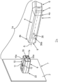
- a household appliance which here is a household cooling appliance 1 as an household apllicance.
- the household cooling appliance 1 comprises an arrangement 1a.
- the household cooling appliance 1 comprises a housing 1b.
- a receiving space 1c for receiving food is configured.
- the receiving space 1c may be a cooling compartment or a freezer compartment.
- the receiving space 1c is bounded by walls of an inner liner 1d of the household cooling appliance 1.
- the household cooling appliance 1 moreover comprises a door 1e. Same is swivably arranged on the housing 1b for closing the receiving space 1c.
- the door 1e comprises a wall 1f, which is an inner liner.
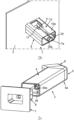
- FIG. 2a in an exploded view an embodiment of an arrangement 1a is shown.
- the arrangement 1a is configured for being mounted on at least one wall 2 of the household appliance, in particular the household cooling appliance 1.
- the mounting viewed in general, is envisaged to be performed on a wall structure with a first wall and a second wall that is separate therefrom.
- the wall structure may be formed by an inner wall and an adjacent, but spaced apart outer wall.
- the wall 2 may be the wall 1f or may be a wall of the inner liner 1d.
- the arrangement 1a comprises a camera 3.
- the camera 3 comprises a camera housing.
- the camera housing is here for instance configured to be made of several parts. It comprises in an embodiment an oblong, straight housing duct 4 or a housing channel, respectively.
- the camera housing in the embodiment comprises an arc segment 5.
- the arc segment 5 is configured for assembly with the housing duct 4.
- a snap-fit connection is provided.
- the oblong housing duct 4 comprises a longitudinal axis A. On an end 4a of the housing duct 4 that faces away from the wall 2 the connection to the arc segment 5 is provided. In the cross-section this oblong housing duct 4 is of a rectangular design. However, it may also have a different shape design.
- the housing duct 4 on a rear end 4b which in the mounted state faces the wall 2, is configured for mounting on a support part 6.
- the camera 3 may be arranged on the door 1e of the household cooling appliance 1. However, it may also be arranged on the inner liner 1d bounding the receiving space 1c for food. By the camera 3 the receiving space 1c is to be captured.
- the camera 3 in the embodiment also comprises a front part 6.
- the arrangement 1a further comprises a support part 7.
- the support part 7 is separate from the camera 3.
- the support part 7 in the embodiment is an integrally formed component. It may in particular be configured to be made of plastic.
- the support part 7 is arranged at the wall 2 such that only a mounting socket 8 can be seen.
- the support part 7 comprises a mounting socket 8.
- This mounting socket 8 is of a socket-shaped design. It may be configured to be hollow in part.
- the mounting socket 8 preferably comprises a shape design which is also configured for accurately fitting insertion into an interior 9 of the camera housing, in particular of the housing duct 4. This also means that the housing duct 4 is larger than the mounting socket 8 so that the mounting socket 8 in the mounted state may plunge into the interior 9. In particular then in the mounted state the housing duct 4 surrounds this mounting socket 8. In particular in the circumferential direction around the longitudinal axis A the mounting socket 8 then is completely surrounded by the housing duct 4.
- the mounting socket 8 comprises a ceiling wall 10. On this ceiling wall 10 in the embodiment at least one snap-fit element 11, in particular two snap-fit elements 11 and 12, are integrally formed. It is also possible that additionally on a bottom wall 15 ( fig. 3 ) of the mounting socket 8 at least one further snap-fit element, preferably two further snap-fit elements 13 and 14 are integrally formed.
- snap-fit elements 11 and 12 in this regard are configured on an outer side 10a, here a top side, of this ceiling wall 10.
- snap-fit elements 13 and 14 are configured on an outer side 15a, here a bottom side, of the bottom wall 15 of the mounting socket 8.
- a first electrical plug connector 35 is disposed in an interior 7a of the support part 7 and a second electrical plug connector 36 is disposed inside an interior 9 of the camera housing, wherein the second electrical plug connector 36 is configured for connection to the first electrical plug connector 35.
- the first 35 and second electrical plug connectors 36 are separate component and completely disposed inside the interior 7a of the support part 7 and interior 9 of the camera housing.
- the first electrical plug connector 35 may be fastened, e. g. by way of a force-fit, form-fit, and/or snap-fit connection, inside the interior, especially the housing duct, of the support part and the second electrical plug connector 36 may be fastened, e. g.
- the first electrical plug connection 35 may have first snap-fit element 35a, e.g. a hook or lug, which is configured to be directly connected to a second snap-fit element 36a, e. g. a hook or lug, of the second electrical plug connection 36.
- the second electrical plug connector 36 may be further connected to the first electrical plug connector 35 directly by way of a further snap-fit connection 35a, 36a and thus snap-fitted thereto in the mounted state.
- the plug connectors 35, 36 are connected to one another individually, namely by way of the further snap-fit connection 35a, 36a.
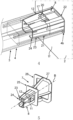
- FIG. 2b a perspective view of an embodiment of a support part 7 is shown.
- the first electrical plug connector 35 and the first snap-fit element 35a are shown.
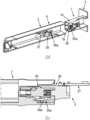
- FIG. 2d a perspective cross section view of an exploded view of an arrangement comprising the camera 3 and the support part 7 is shown.
- the position and the orientation and geometries of the snap-fit elements 35a and 36a are demonstrated as examples.
- fig. 2e a cross section view of parts of the arrangement of fig. 2d in a coupled state are shown.
- a circuit board 37 arranged within the camera 3 and connected to the second connector 36 is shown.
- the snap-fit elements 35a and 36a are in snap-fitted arrangement.
- the view in fig. 2e is in direction to the other half side of the arrangement in fig. 2d , wherein for this situation the camera 3 is on the right side and the support part 7 is on the left side. Further the housing duct 4 is not shown in fig. 2e .
- the second snap-fit element 36a is a block like element in this embodiment.
- the first snap-fit element 35a is a cantilevered element and/or especially a springy element.
- the camera housing in particular the housing duct 4, comprises a ceiling wall 16.
- a counter-snap element 17 is configured on an inner side 16a .
- the housing duct 4 comprises a bottom wall 18.
- a further counter-snap element 19 is configured on an inner side 18a of this bottom wall 18 .
- a snap-fit element receptacle is envisaged that in the mounted state the snap-fit elements 11 and 12 are snap-fitted into the counter-snap element 17 and the snap-fit elements 13 and 14 into the counter-snap element 19.
- the wall 2 comprises an opening 22. Through this opening 22 extends the mounting socket 8.
- the support part 7 is arranged on both sides of this opening 22.
- the mounting socket 8 is completely received in the interior 9 of the camera housing.
- the mounting socket 8 on its shell side is completely surrounded by the camera housing, in particular the housing duct 4.
- the snap-fit connections 20 and 21 are configured to be completely internally positioned in the interior 9 of the camera housing. They are therefore not uncovered towards the outside.
- the mounting socket 8 comprises a tapering front portion 23. The front portion 23 thus tapers towards a free front end 24.
- the slope-like shape of the snap-fit elements 11 and 12 may also be discerned in fig. 4 .
- the mounting socket 8 in the embodiment in fig. 4 is also configured to be hollow at least in part, as this is already shown for the embodiments in fig. 2 and fig. 3 .
- the support part 7 comprises a support plate 25.
- This is here configured as circumferential, in particular annular, support flange.
- this support plate 25 directly adjoins the mounting socket 8.
- the support part 7 in the shown embodiment in fig. 5 comprises a support structure 26. Same directly adjoins the support plate 25 towards the rear.
- the support structure 26 is here of a bar-like design. Starting from the support plate 25 towards the rear and thus facing away from the mounting socket 8 it is configured to be widening.
- the support structure 26 in the example is configured as basket structure. In particular, it comprises a rear contact flange 27 forming the end of the support structure 26. Same is here of an annular design.
- a mounted end state in which the support part 7 is mounted and the camera 3 is equally mounted on the support part 7.
- the support part 7 with the support structure 26 is arranged in a clearance 28.
- This clearance 28 is bounded by two walls 2 of the wall structure. Therein, one of the walls 2 may be the inner wall 1f. The other wall 2 may be an outer wall 1g.
- a thermally insulated material may be inserted. This is in particular the case if this structure is integral part of a household cooling appliance.
- the support plate 25 rests against an outer side 29 of the wall 1f, which is an inner wall.
- the support structure 26, in particular with the rear contact flange 27 rests against an inner side 30 of the outer wall 1g.
- respective adhesive bonds such as for instance a double-sided adhesive tape, are provided in each case.
- the support structure 26 extends across the entire inner width of the clearance 28 so that by the support structure 26 and the support plate 25, which may also be regarded as integral part of the support structure 26 in an example, also a positioning structure, which makes contact on both sides, is configured.
- the camera housing in particular the housing duct 4 has completely received the mounting socket 8. It may be that the rear end 4b also rests against the wall 2, in particular the inner wall 1f.
- FIG. 7 in a schematic representation an intermediate mounting step for mounting a household appliance component of the household appliance 1, here in particular the door 1e, is shown.
- the outer wall 1b is provided.
- the support part 7 is fastened, in particular by the adhesive bond.
- the contact flange 27 is glued to the inner side 30 by a double-sided adhesive tape.
- the equally provided wall 2, which here represents the inner wall 1f, in the following is applied to the outer wall 1b. This may for instance also be effected by a swiveling, as it is shown in fig. 8 in a further mounting intermediate state. This applying of the inner wall 1f to the outer wall 1g is effected long enough for the clearance 28 to be also formed.
- the mounting socket 8 of the support part 7 is passed through the opening 22 and the support plate 25 then directly rests against the outer side 29.
- the double-sided adhesive tape which has in particular been applied to the support plate 25 in advance, then creates an adhesive bond with the outer side 29.
- thermally insulating material is introduced into the clearance 28.
- the above-named snap-fit connections 20 and 21 are conceived in such a way that upon pulling the mounted camera 3 in the direction of the longitudinal axis A away from the mounting socket 8, whilst overcoming a predetermined force threshold value, these snap-fit connections 20, 21 may be automatically released.
- This force threshold value is large enough so that by simple slight pulling of the camera 3 or by a minor exertion of force when hitting the camera 3, this release of the snap-fit connections 20 and 21 does not yet occur.
- the cable 31 is guided to an upper door end part 32 of the door 1e, wherein these cables 31 lead to the support part 7.
- the camera housing in particular the housing duct 4, with its rear end 4b in part plunges into a funnel-like receptacle, which encircles the opening 22 in a boundary manner.
- the rear end 4b thus minimally plunges into the inner wall 1f.
Landscapes
- Engineering & Computer Science (AREA)
- Physics & Mathematics (AREA)
- Chemical & Material Sciences (AREA)
- Combustion & Propulsion (AREA)
- Mechanical Engineering (AREA)
- Thermal Sciences (AREA)
- General Engineering & Computer Science (AREA)
- General Physics & Mathematics (AREA)
- Multimedia (AREA)
- Signal Processing (AREA)
- Accessories Of Cameras (AREA)
Abstract
An aspect of the invention relates to a household appliance (1), comprising a housing (1b), in which at least one receiving space (1c) for food is configured, with a door (1e), which is movably arranged on the housing (1b), and comprising a camera (3), wherein the camera (3) comprises a camera housing (4, 5, 6), and comprising a support part (7), which comprises a mounting socket (8), which is connected to the camera housing (4, 5, 6) by a snap-fit connection (20, 21), characterized in that the mounting socket (8) on an outer side (10a, 15a) comprises at least one snap-fit element (11, 12) and the camera housing (4, 5, 6) on an inner side (16a, 18a) comprises a counter-snap element (17, 19), wherein in the mounted state the mounting socket (8) is received in the camera housing (4, 5, 6) and the snap-fit element (11, 12) for creating the snap-fit connection (20, 21) is snap-fitted with the counter-snap element (17, 19). One aspect also relates to a method.
Description
- One aspect of the invention relates to a household appliance comprising a housing, in which at least one receiving space for food is configured. The household appliance moreover comprises a door, which is movably arranged on the housing. Moreover, the household appliance comprises a camera. Same may be arranged on an inner side of the door. A further aspect of the invention relates to a method for mounting a camera for a household appliance.
- From
document DE 10 2013 211 099 A1 a household cooling appliance is known. There a camera module is provided, which may also comprise a lighting device. - Moreover, from
document EP 2 975 343 A1 a cooling appliance is known. On an inner side of the door there is a camera arranged. Equally, thereby a lighting unit is arranged on the inner side of the door. - In the case of modern household appliances, such as for instance a household cooling appliance, it is known that at least one camera is present, by which a receiving space for food may be captured. In the case of household cooling appliances it is known that such a camera is arranged on a wall of an inner liner bounding the receiving space. Since especially in the case of household cooling appliances a thermal insulation between the inner liner and the outer housing of the household cooling appliance is required, such fastening is more difficult. In order to facilitate this, in addition to a camera a support part is used. This is usually arranged in a clearance between the inner liner and the outer housing. The support part is thus arranged in particular on the side of the foam. This means that it is arranged in the clearance between the inner liner and the outer housing, into which thermally insulating foam is inserted.
- Such design is for instance known from the
DE 10 2013 216 767 A1 . Such a support part is snap-fitted in a recess of a wall of the inner liner. Moreover, there a carrier for a camera housing and a lighting unit is inserted into the support part and at the same time snap-fitted therein. However, there the camera housing is introduced into the support part so that it is surrounded by the support part. Thereby the fixing of the camera in position is more difficult and these transitions are visible on the outside. Thus, dirt etc. may accumulate on these transitions. - From
document DE 10 2020 210 278 A1 a household cooling appliance is known, which comprises a camera arranged by a snap-fit connection on the support part. - It is the object of the present invention to provide a household device, in which the arrangement of a camera on a support part is improved by a snap-fit connection. Equally a method is to be provided.
- This object is solved by a household appliance and a method according to the independent claims.
- One aspect of the invention relates to a household appliance comprising a housing, in which at least one receiving space for food is configured. The household appliance moreover comprises a door, which is movably arranged on the housing. Moreover, the household appliance comprises a camera.
- The camera comprises a camera housing. Moreover, the household appliance comprises a support part comprising a mounting socket. The support part can be described as reinforcement part, too. This mounting socket is connected to the camera housing by a snap-fit connection. It is of the essence that the mounting socket on an outer side comprises at least one snap-fit element. The camera housing on an inner side comprises at least one counter-snap element. In the mounted state the mounting socket is received in the camera housing. The snap-fit element is snap-fitted with the counter-snap element for creating the snap-fit connection. By such a specific arrangement between the mounting socket and the camera housing, in which the camera housing quasi surrounds the mounting socket and the snap-fit connection is arranged to be internally positioned, the mechanically stable connection between the two components may be improved. Moreover, the snap-fit connection is arranged to be protected. Movement tolerances between the components may thereby be reduced.
- In an embodiment in the mounted state the mounting socket is completely received in the interior of the camera housing. The protected position of the snap-fit connection is thereby once again improved. Moreover, the mounting socket in the mounted state is not visible to the outside. Thus, the camera housing completely covers the mounting socket. Thereby, the mounting socket is arranged equally protected. Also, thus, the complete stable positioning of the camera housing on the mounting socket is improved. Also, the mounting socket thereby is better protected by the camera housing also in the opposite direction.
- In an embodiment the mounting socket on its shell side is completely surrounded by the camera housing. Thus, viewed in the direction of a socket axis the mounting socket, which is a longitudinal axis of the mounting socket, the mounting socket may plunge into the camera housing. In the circumferential direction around this longitudinal axis the mounting socket is thus completely covered by the camera housing towards the outside. Such a complete external surrounding of the mounting socket by the camera housing in this direction supports the above-named advantages once more.
- In an embodiment the snap-fit connection is configured to be completely internally positioned in the interior of the camera housing. In particular, thus it is also achieved that an undesired releasing of the snap-fit connection occurs.
- In an embodiment, the mounting socket is connected to a support plate. The support plate may be a support flange. Same may be configured to be annular. The support flange according to its intended purpose is provided for resting against a wall of the inner liner, in particular an outer side of a wall of an inner liner of a household cooling appliance provided in the embodiment. By such a support plate or a support flange, respectively, the positioning of the mounting socket on this wall that is separate therefrom is improved. In particular, it is thereby also achieved that an increased contact surface for the mounting socket on this wall is achieved. Mechanically more stable fastenings as well as an arrangement in a more precise position are thereby facilitated.
- In an embodiment, the support plate and the mounting socket are configured to be integrally formed. Thus, the number of components of the mounting socket may be reduced. Also mounting effort and position tolerances may thereby be avoided, since these two components invariably remain in the same position relative to each other.
- In an embodiment, the mounting socket is configured to be hollow at least in part. It is in particular configured to be tube-like. Thereby, the weight of the mounting socket may be reduced. Nevertheless, its stability is high. Thus, both coupling forces with the camera housing as well as lever forces acting upon the mounting socket in the mounted state through the camera housing can be easily absorbed. The camera housing may be arranged to be freely cantilevering.
- In an embodiment, the snap-fit element is integrated in a wall of the mounting socket. Thus, the snap-fit element is integrally formed with this wall.
- It may be envisaged that the snap-fit element is arranged in fixed position on the wall. In another embodiment, it may also be configured to be slightly resilient. It may be integral part of a spring shackle.
- In an embodiment, the snap-fit element is configured to be slope-like. Thus, a start-up slope may be provided, by which a highly continuous mounting process, in particular a attachment process of the camera housing onto the mounting socket is facilitated. If this slope of the snap-fit element is overcome by the counter-snap element in the axial direction of the mounting direction, the counter-snap element is snap-fitted on the snap-fit element.
- In an embodiment, the mounting socket comprises a ceiling wall. In same a first snap-fit element is configured to be integrated. The mounting socket in particular comprises a bottom wall. In same in particular a second snap-fit element is configured to be integrated. The camera housing preferably comprises a ceiling wall, in which a first counter-snap element is configured to be integrated. The camera housing preferably comprises a bottom wall, in which a second counter-snap element is configured to be integrated. In the mounted state between the first snap-fit element and the first counter-snap element a first snap-fit connection is configured. Between the second snap-fit element and the second counter-snap element then a second snap-fit connection is configured. By such an, in particular at least one top snap-fit connection and at least one further bottom snap-fit connection that is separate therefrom and different in terms of location the fastening concept with only snap-fit connections is configured particularly advantageously. This is because thus fixing the camera housing in position on the mounting socket is improved.
- In particular the camera housing and the mounting socket are only coupled by snap-fit connections to each other. Further fastening elements, such as for instance screws or the like, are not provided. Also, this is particularly advantageously facilitated by the camera housing being externally positioned and the mounting socket being arranged in the interior of the at least in part hollow camera housing.
- In an embodiment, the mounting socket comprises a tapering front portion. Also thereby the inserting of the camera housing is supported. A jam-free and initially at the beginning of the insertion inaccurately positioned arranging of the camera housing relative to the mounting socket is thereby facilitated. By this front portion, which tapers towards the front towards its free end, also a guiding for the camera housing is facilitated, when this camera housing is slid onto the mounting socket. Thus, in this mounting process and when axially sliding the camera housing onto the mounting socket also a self-alignment of the two components relative to one another is achieved by the tapering front portion.
- In an embodiment, a first electrical plug connector is disposed in an interior of the support part and a second electrical plug connector is disposed inside an interior of the camera housing, wherein the second electrical plug connector is configured for connection to the first electrical plug connector. The first and second electrical plug connectors are separate component and completely disposed inside the interior, especially housing duct, of the support part and interior, especially housing duct, of the camera housing. This first electrical plug connector may be fastened, e. g. by way of a force-fit, form-fit, and/or snap-fit connection, inside the interior of the support part and the second electrical plug connector may be fastened, e. g. by way of a force-fit, form-fit, and/or snap-fit connection, inside the housing duct of the camera housing. The first electrical plug connection may have first snap-fit element, e.g. hook or lug, which is configured to be directly connected to a second snap-fit element, e.g. hook or lug, of the second electrical plug connection. In this way, the second electrical plug connector may be connected to the first electrical plug connector directly by way of a further snap-fit connection and thus snap-fitted thereto in the mounted state. The plug connectors are connected to one another individually, namely by way of the further snap-fit connection. As a result, a simple mounting concept can be achieved. The two plug connectors are then also held together in a mechanically stable and precisely positioned manner. A snap-fit connection of this type, in which the two electrical plug connectors are further directly snap-fitted to one another, can be produced quickly, easily and expediently, and on the other hand can also be released again easily. As a result, when the camera and the support part are joined together mechanically, the mechanical and thus also the electrical connection between the two plug connectors is then achieved automatically in a particularly simple manner. A mounting effort, in particular a positioning and cabling effort for the individual plug connectors, in particular after the mounting of the camera on the reinforcement part, is thus significantly reduced. The proposed concept thus also makes it possible for the camera to be joined effectively blindly to the support part and in this regard for the two electrical plug connectors to be plugged together automatically, also effectively without sight, during this joining process. As a result, no separate, additional work step is required in order to join the two plug connectors together.
- In an embodiment, the support part comprises a support structure that is different from the mounting socket. By same the support part is supported in a clearance between the inner wall and an outer wall of a household appliance component, for instance the door. Thus, a further advantageous fixing of the mounting socket in position is achieved. This is because the mounting socket may be fastened to rest against two different walls of the door. Especially in the case of a door of a household cooling appliance, which is also thermally insulating, and in which thermally insulating material is inserted between the inner wall and the outer wall, thus this positioning of the mounting socket is improved once again. This is particularly advantageous, when in the concept suggested above the mounting socket protrudes through the opening in the at least one wall to then be capable of being connected to the camera housing on the other side of the wall. Since preferably the mounting socket in this regard has to be dimensioned smaller, in particular with its at least one snap-fit element, in order to be able to be passed through this opening, in the end position of the mounting socket on the wall, in particular the inner wall, there is also a certain tolerance between the mounting socket and the bounding edge of this opening. Thus, at least in theory, a certain relative movement of the mounting socket of the support part may be effected relative to this opening. Due to the support structure this may be avoided, since also when the camera housing is not yet fastened to the mounting socket and the mounting socket or the support part, respectively, is already arranged in the mounted end position, a fixing in position is achieved. This is because this is in particular achieved by the support structure, which rests against two different components, namely the inner wall and the outer wall.
- In an embodiment the support structure rests against an inner side of the outer wall which faces the clearance. Moreover, in an embodiment the support plate already named above, in particular the support flange, rests against an outer side of the inner wall. Thus, on the one hand, by the support plate, on the other hand, by the support structure, a resting of the support part against two different walls at the same time is achieved. In particular, by the support structure the clearance across its entire inner width is bridged so that the support structure together with the support plate extends across this entire inner width between the outer side of the inner wall and the inner side of the outer wall. Thus, the support structure with the support plate in an embodiment, to a certain extent, is also arranged to be straddled or slightly wedged between these two sides.
- It is possible that the support structure on the inner side of the outer wall is fastened thereto by an adhesive bond, in particular by a double-sided adhesive tape. In an embodiment, it is possible that the support plate by an adhesive bond, in particular a double-sided adhesive tape, is fastened to the outer side of the inner wall. Such adhesive bonds are fast and easy to manufacture and still allow for highly accurate fixing in position of the named components relative to each other. In particular this holding is also sustained if subsequently during the manufacturing process thermally insulating material, such as for instance also thermal insulation foam, is introduced into the clearance. Then, too, the support structure and thus also the support part remain in the fixed position.
- In an embodiment, the support structure is configured to be basket-like. In particular it is configured as basket structure widening towards the outer wall. Such a basket structure, which thus also represents a bar structure or a framework structure, on the one hand, is inherently mechanically stable, on the other hand, configured with low weight. Particularly advantageous is such a very permeable support structure if as thermally insulating material insulation foam is introduced. This is because then this insulation foam upon introduction may also completely penetrate the support structure and also preferably fill the entire area relatively void-free.
- A further aspect of the invention relates to a method for manufacturing a household appliance component, in particular a door, for a household appliance, in particular a household cooling appliance, comprising the following steps:
- mounting a support part on an inner wall of the household appliance component so that a mounting socket of the support part protrudes through an opening in the inner wall;
- sliding a camera housing of a camera onto the mounting socket so that the camera housing receives the mounting socket in the interior and in the end position of the camera housing at least one snap-fit element of the mounting socket is snap-fitted with at least one counter-snap element of the camera housing and thereby a snap-fit connection located in the interior of the camera housing is created; and/or
- attaching an outer wall of the housing appliance component so that a clearance between the inner wall and the outer wall is formed, wherein by attaching the outer wall a support structure of the support part is arranged in the clearance and the support structure is brought into mechanical contact with the outer wall and rests against it.
- In an embodiment of the method, it is envisaged that an outer wall is provided. This outer wall may be an outer wall of a door of the household appliance, in particular of a household cooling appliance. On an inner side of this outer wall this support part is attached with the support structure, in particular directly, preferably with a double-sided adhesive tape, glued thereon. Further, then the inner wall provided separately therefrom is then moved towards the outer wall, for instance swiveled open from its mounting deposit position onto the outer wall. Therein, the mounting socket is passed through the opening in the inner wall and the support plate of the support part rests against the outer side of the inner wall. In particular here also by a double-sided adhesive tape then automatically an adhesive bond is created between the support plate and the outer side of the inner wall.
- In the camera housing an image capture unit and a lighting unit of the household appliance may be arranged. The lighting unit is configured for long-term lighting of the surroundings of the camera.
- In an embodiment, the lighting unit comprises at least one light source. The lighting unit comprises at least one optically effective element, in particular a lens. The lens is in particular positioned in the beam path of the light source. Thus, the light of the light source may also be directed in a targeted way through this lens. The light source may be at least one light-emitting diode. These may also be several light-emitting diodes.
- In an embodiment, the lighting unit may also comprise an image projector. Thus, it is then also facilitated to not only emit simple light, but also to represent image information. Accordingly, these may be images of the most varied objects or other items.
- In an embodiment the household appliance comprises a door position recognition unit. According to the intended purpose this is provided for capturing the position of the door of the household appliance. It may be envisaged that the door position recognition unit also comprises a control unit. Depending on the recognized door position, the lighting unit may then automatically be activated or deactivated. This may then be effected in a controlled way via the control unit. In particular it is envisaged that the lighting unit is deactivated in the closed state of the door. If the door is opened, the lighting unit is automatically activated. It may then light up permanently and without interruption for as long as the door is open. If the door is closed again, the lighting unit is deactivated automatically again. Thus, an energy-efficient operation of the lighting unit may be effected. Moreover, it is avoided that the lighting unit continues to be active also in the closed state of the door. Especially in the case of household cooling appliances it is thereby avoided that an undesired heat input into a cooling compartment or a freezer compartment occurs, if the lighting unit also were lighting up in the closed state of the door.
- The door position recognition unit may comprise one or several sensors, by which the door position may be captured. For instance, this may be at least one magneto-resistive sensor. Also a mechanical sensor may be provided. Equally, however, also capacitive or inductive proximity sensors or else also an acceleration sensor may be provided.
- The camera housing preferably comprises a housing duct and a front part.
- In an embodiment the front part comprises a front wall. In this front wall a first, transparent window or viewing window, respectively, is configured, through which light is hitting the image capture unit from outside the camera. In an embodiment the front wall comprises a second transparent window that is separate from the first transparent window, through which the light of the flash light unit exits towards the outside. By this separation of the two windows undesired light impairments may be avoided. The direct incidence of the flash light towards the image-capturing unit may be avoided by this window separation.
- In an embodiment the camera housing of the camera comprises a front part that is separate from the housing duct. In an embodiment, this housing duct is connected to the front part by at least one snap-fit connection. Such a specific non-destructively releasable mechanical connection is easy to produce. It may then also be easily released for maintenance purposes, if required. By the housing being composed of two separate components, the mounting of individual components of the camera in the housing duct, on the one hand, in the front part, on the other hand, may be effected in a more individual and improved manner. Thus, also more exact positions of the individual components in the two parts of the housing can be achieved in an improved way. Not least, thus then also the accessibility to the individual components, which are installed in these two housing parts, is improved.
- In an embodiment, the housing duct is configured to be straight and tube-like. In particular in this connection it may be a rectangular tube. The housing duct with regard to its basic geometry in the embodiment is symmetrical to a plane, which is configured to extend perpendicularly to the longitudinal axis of the housing duct. In this regard, thus, the opposite ends of the housing shaft may be configured to be equal in size. By such a design, on the one hand, a relatively simple housing part is created, which can, however, receive corresponding components, on the other hand, and facilitates a mechanically stable connection with camera-external components. On the other hand, it is also configured to be correspondingly mechanically stable and resilient. Thereby, in an embodiment, also a further coupling with housing parts of the camera may be easily effected. This may for instance be a separate front part and/or in a further embodiment an additional separate arc segment of the housing of the camera. This also makes it easy to provide a correspondingly high number of variants for the design of various camera types.
- In an embodiment, the housing duct is configured to be made of plastic. For instance this may be an injection-molded part.
- In an embodiment, the camera housing of the camera comprises a separate, hollow arc segment. In an embodiment, viewed in the direction of the longitudinal axis of the housing, this is arranged between the front part, on the one hand, and the housing duct, on the other hand. The arc segment is in particular configured as angle position adapter for the front part. The arc segment is non-destructively releasably connected to the front part, on the one hand, and the housing duct, on the other hand. The complete housing is then formed by the parts that are arranged in series relative to one another comprising the housing duct, the arc segment, and the front part. By this arc segment thus a specific orientation of the capturing range of the image-capturing module can be adjusted. In this embodiment, it is then facilitated by the arc segment that a main axis of the capture range of the image capture module is oriented at an angle to the longitudinal axis of the housing duct. This angle is larger than 0° and smaller than 180°. In particular, it may be between 100° and 170°.
- The named housing parts are in particular outer parts and as such visible components.
- This arrangement with the camera and the support part can thus be arranged on a wall of an inner liner of the household cooling appliance. The wall of the household cooling appliance, however, may then also be for instance integral part of a door of the household cooling appliance. For instance this may be the inner liner of the door. This is an example of an inner part. The inner liner in the closed state of the door is facing the receiving space of the household cooling appliance. Also, this inner lining is a visible component of the door. Also, thereby a clearance between an outer cladding as example of an outer part and an inner liner of the door may be bounded. Also in this clearance thermally insulated material may be introduced.
- Advantageous embodiments of the household appliance are to be considered as advantageous embodiments of the method. In this regard, the individual components of the camera are suited for facilitating the corresponding steps in the mounting of the camera. For this purpose, individual components may comprise corresponding auxiliary means for performing the mounting steps and/or several components of the camera in effective connection with one another for facilitating the mounting scenario.
- By the indications "top", "bottom", "front", "back", "horizontal", "vertical", "depth direction", "width direction", "height direction" the positions and orientations given in the case of use according to the intended purpose and positioning according to the intended purpose are indicated.
- Further features of the invention derive from the claims, the figures, and the description of the figures. The features and feature combinations previously named in the description, as well as the features and feature combinations named in the following in the description of the figures and/or shown in the figures alone can be used not only in the respectively indicated combination, but also in other combinations or alone, without leaving the scope of the invention. Thus, also implementations of the invention are to be considered as comprised and disclosed, which are not explicitly shown and explained in the figures, however derive from separated feature combinations from the explained implementations and can be generated from them. Also explanations and feature combinations are to be regarded as disclosed, which thus do not comprise all features of an originally formulated independent claim.
- Embodiments of the invention are explained in more detail in the following by reference to schematic drawings. These show in:
- Fig. 1
- a schematic representation of an embodiment of a household appliance;
- Fig. 2a
- an exploded view of an arrangement comprising a camera and a support part;
- Fig. 2b
- a perspective view of an embodiment of a support part;
- Fig. 2c
- a further exploded view of an arrangement comprising a camera and a support part;
- Fig. 2d
- a perspective cross section view of an exploded view of an arrangement comprising a camera and a support part;
- Fig. 2e
- a cross section view of parts of the arrangement of
fig. 2d ; - Fig. 3
- a partial view of the components of the arrangement according to
Fig. 2 ; - Fig. 4
- a perspective view, in which the camera is fastened to a mounting socket of the support part by snap-fit connections;
- Fig. 5
- a perspective view of an embodiment of a support part comprising a support structure and a mounting socket;
- Fig. 6
- a perspective view of a mounted end state of the support part on an outer wall and an inner wall and of a mounted end state of the camera on the support part;
- Fig. 7
- a schematic representation of an intermediate mounting state for mounting a household appliance component of a household appliance; and
- Fig. 8
- a further intermediate mounting state following the intermediate mounting state in
Fig. 7 . - In the figures identical or functionally identical elements are equipped with the same reference signs.
- In
fig. 1 in a schematic representation a household appliance is shown, which here is ahousehold cooling appliance 1 as an household apllicance. Thehousehold cooling appliance 1 comprises anarrangement 1a. Thehousehold cooling appliance 1 comprises ahousing 1b. Therein a receivingspace 1c for receiving food is configured. The receivingspace 1c may be a cooling compartment or a freezer compartment. The receivingspace 1c is bounded by walls of aninner liner 1d of thehousehold cooling appliance 1. Thehousehold cooling appliance 1 moreover comprises adoor 1e. Same is swivably arranged on thehousing 1b for closing the receivingspace 1c. Thedoor 1e comprises awall 1f, which is an inner liner. - In
fig. 2a in an exploded view an embodiment of anarrangement 1a is shown. Thearrangement 1a is configured for being mounted on at least onewall 2 of the household appliance, in particular thehousehold cooling appliance 1. - In particular the mounting, viewed in general, is envisaged to be performed on a wall structure with a first wall and a second wall that is separate therefrom. The wall structure may be formed by an inner wall and an adjacent, but spaced apart outer wall.
- The
wall 2 may be thewall 1f or may be a wall of theinner liner 1d. Thearrangement 1a comprises acamera 3. Thecamera 3 comprises a camera housing. The camera housing is here for instance configured to be made of several parts. It comprises in an embodiment an oblong,straight housing duct 4 or a housing channel, respectively. Moreover, the camera housing in the embodiment comprises anarc segment 5. Thearc segment 5 is configured for assembly with thehousing duct 4. In particular here a snap-fit connection is provided. Theoblong housing duct 4 comprises a longitudinal axis A. On anend 4a of thehousing duct 4 that faces away from thewall 2 the connection to thearc segment 5 is provided. In the cross-section thisoblong housing duct 4 is of a rectangular design. However, it may also have a different shape design. As may be discerned, thehousing duct 4 on arear end 4b, which in the mounted state faces thewall 2, is configured for mounting on asupport part 6. - The
camera 3 may be arranged on thedoor 1e of thehousehold cooling appliance 1. However, it may also be arranged on theinner liner 1d bounding the receivingspace 1c for food. By thecamera 3 the receivingspace 1c is to be captured. - The
camera 3 in the embodiment also comprises afront part 6. - The
arrangement 1a further comprises asupport part 7. Thesupport part 7 is separate from thecamera 3. Thesupport part 7 in the embodiment is an integrally formed component. It may in particular be configured to be made of plastic. Here, thesupport part 7 is arranged at thewall 2 such that only a mountingsocket 8 can be seen. - In
fig. 2a thesupport part 7 comprises a mountingsocket 8. This mountingsocket 8 is of a socket-shaped design. It may be configured to be hollow in part. The mountingsocket 8 preferably comprises a shape design which is also configured for accurately fitting insertion into aninterior 9 of the camera housing, in particular of thehousing duct 4. This also means that thehousing duct 4 is larger than the mountingsocket 8 so that the mountingsocket 8 in the mounted state may plunge into theinterior 9. In particular then in the mounted state thehousing duct 4 surrounds this mountingsocket 8. In particular in the circumferential direction around the longitudinal axis A the mountingsocket 8 then is completely surrounded by thehousing duct 4. - The mounting
socket 8 comprises aceiling wall 10. On thisceiling wall 10 in the embodiment at least one snap-fit element 11, in particular two snap-fit elements fig. 3 ) of the mountingsocket 8 at least one further snap-fit element, preferably two further snap-fit elements - These snap-
fit elements outer side 10a, here a top side, of thisceiling wall 10. In particular the snap-fit elements outer side 15a, here a bottom side, of thebottom wall 15 of the mountingsocket 8. - In
fig. 2a , a firstelectrical plug connector 35 is disposed in an interior 7a of thesupport part 7 and a secondelectrical plug connector 36 is disposed inside aninterior 9 of the camera housing, wherein the secondelectrical plug connector 36 is configured for connection to the firstelectrical plug connector 35. The first 35 and secondelectrical plug connectors 36 are separate component and completely disposed inside the interior 7a of thesupport part 7 andinterior 9 of the camera housing. The firstelectrical plug connector 35 may be fastened, e. g. by way of a force-fit, form-fit, and/or snap-fit connection, inside the interior, especially the housing duct, of the support part and the secondelectrical plug connector 36 may be fastened, e. g. by way of a force-fit, form-fit, and/or snap-fit connection, inside the interior, especiallyhousing duct 4, of the camera housing. The firstelectrical plug connection 35 may have first snap-fit element 35a, e.g. a hook or lug, which is configured to be directly connected to a second snap-fit element 36a, e. g. a hook or lug, of the secondelectrical plug connection 36. In this way, the secondelectrical plug connector 36 may be further connected to the firstelectrical plug connector 35 directly by way of a further snap-fit connection plug connectors fit connection - In
fig. 2b a perspective view of an embodiment of asupport part 7 is shown. The firstelectrical plug connector 35 and the first snap-fit element 35a are shown. - In
fig. 2c a further exploded view of an arrangement comprising thecamera 3 and asupport part 7 is shown. The secondelectrical plug connector 36 and the second snap-fit element 36a are shown. - In
fig. 2d a perspective cross section view of an exploded view of an arrangement comprising thecamera 3 and thesupport part 7 is shown. The position and the orientation and geometries of the snap-fit elements - In
fig. 2e a cross section view of parts of the arrangement offig. 2d in a coupled state are shown. Acircuit board 37 arranged within thecamera 3 and connected to thesecond connector 36 is shown. The snap-fit elements fig. 2e is in direction to the other half side of the arrangement infig. 2d , wherein for this situation thecamera 3 is on the right side and thesupport part 7 is on the left side. Further thehousing duct 4 is not shown infig. 2e . - As it can be seen in
fig. 2d and 2e the second snap-fit element 36a is a block like element in this embodiment. The first snap-fit element 35a is a cantilevered element and/or especially a springy element. - As may moreover be discerned in
fig. 4 , the camera housing, in particular thehousing duct 4, comprises aceiling wall 16. On aninner side 16a acounter-snap element 17 is configured. In particular this is a snap-fit element receptacle. Moreover, thehousing duct 4 comprises abottom wall 18. In particular on aninner side 18a of thisbottom wall 18 a furthercounter-snap element 19 is configured. This, too, is a snap-fit element receptacle. It is envisaged that in the mounted state the snap-fit elements counter-snap element 17 and the snap-fit elements counter-snap element 19. - In particular the mechanical coupling between the camera housing, in particular the
housing duct 4, and the mountingsocket 8 is held only by these snap-fit connections 20 and 21 (fig. 4 ). - As can be discerned in
fig. 2 andfig. 3 , thewall 2 comprises anopening 22. Through thisopening 22 extends the mountingsocket 8. Thus, thesupport part 7 is arranged on both sides of thisopening 22. In the mounted end state of thehousing duct 4 on the mountingsocket 8, as it is shown infig. 4 , the mountingsocket 8 is completely received in theinterior 9 of the camera housing. The mountingsocket 8 on its shell side is completely surrounded by the camera housing, in particular thehousing duct 4. As may be moreover discerned infig. 4 , the snap-fit connections interior 9 of the camera housing. They are therefore not uncovered towards the outside. In the embodiment infig. 4 in contrast to the examples infig. 2 andfig. 3 it is envisaged that the mountingsocket 8 comprises a taperingfront portion 23. Thefront portion 23 thus tapers towards a freefront end 24. - The slope-like shape of the snap-
fit elements fig. 4 . - The mounting
socket 8 in the embodiment infig. 4 is also configured to be hollow at least in part, as this is already shown for the embodiments infig. 2 andfig. 3 . - In
fig. 5 in a perspective view an embodiment of an integrally formedsupport part 7 is shown. In this embodiment thesupport part 7 comprises asupport plate 25. This is here configured as circumferential, in particular annular, support flange. In the direction of a longitudinal axis B of thesupport part 7 thissupport plate 25 directly adjoins the mountingsocket 8. Moreover, thesupport part 7 in the shown embodiment infig. 5 comprises asupport structure 26. Same directly adjoins thesupport plate 25 towards the rear. Thesupport structure 26 is here of a bar-like design. Starting from thesupport plate 25 towards the rear and thus facing away from the mountingsocket 8 it is configured to be widening. Thesupport structure 26 in the example is configured as basket structure. In particular, it comprises arear contact flange 27 forming the end of thesupport structure 26. Same is here of an annular design. - In
fig. 6 in a perspective view a mounted end state is shown, in which thesupport part 7 is mounted and thecamera 3 is equally mounted on thesupport part 7. As may be discerned here, thesupport part 7 with thesupport structure 26 is arranged in aclearance 28. Thisclearance 28 is bounded by twowalls 2 of the wall structure. Therein, one of thewalls 2 may be theinner wall 1f. Theother wall 2 may be anouter wall 1g. In the clearance 28 a thermally insulated material may be inserted. This is in particular the case if this structure is integral part of a household cooling appliance. - As may be discerned, the
support plate 25 rests against anouter side 29 of thewall 1f, which is an inner wall. Moreover, thesupport structure 26, in particular with therear contact flange 27 rests against aninner side 30 of theouter wall 1g. In particular here respective adhesive bonds, such as for instance a double-sided adhesive tape, are provided in each case. As may be discerned inFig. 6 , thesupport structure 26 extends across the entire inner width of theclearance 28 so that by thesupport structure 26 and thesupport plate 25, which may also be regarded as integral part of thesupport structure 26 in an example, also a positioning structure, which makes contact on both sides, is configured. Moreover, it may also be discerned that the camera housing, in particular thehousing duct 4 has completely received the mountingsocket 8. It may be that therear end 4b also rests against thewall 2, in particular theinner wall 1f. - In
fig. 7 in a schematic representation an intermediate mounting step for mounting a household appliance component of thehousehold appliance 1, here in particular thedoor 1e, is shown. For this purpose, here theouter wall 1b is provided. On theinner side 30 thesupport part 7 is fastened, in particular by the adhesive bond. In this connection, thecontact flange 27 is glued to theinner side 30 by a double-sided adhesive tape. The equally providedwall 2, which here represents theinner wall 1f, in the following is applied to theouter wall 1b. This may for instance also be effected by a swiveling, as it is shown infig. 8 in a further mounting intermediate state. This applying of theinner wall 1f to theouter wall 1g is effected long enough for theclearance 28 to be also formed. Moreover, then the mountingsocket 8 of thesupport part 7 is passed through theopening 22 and thesupport plate 25 then directly rests against theouter side 29. The double-sided adhesive tape, which has in particular been applied to thesupport plate 25 in advance, then creates an adhesive bond with theouter side 29. - In a further manufacturing step, which is not shown, then thermally insulating material is introduced into the
clearance 28. Preferably, the above-named snap-fit connections camera 3 in the direction of the longitudinal axis A away from the mountingsocket 8, whilst overcoming a predetermined force threshold value, these snap-fit connections camera 3 or by a minor exertion of force when hitting thecamera 3, this release of the snap-fit connections - In the representation in
fig. 6 , in an embodiment, additionally it may also be envisaged that thecable 31 is guided to an upperdoor end part 32 of thedoor 1e, wherein thesecables 31 lead to thesupport part 7. - In an embodiment it is also possible that the camera housing, in particular the
housing duct 4, with itsrear end 4b in part plunges into a funnel-like receptacle, which encircles theopening 22 in a boundary manner. Thus, a further fixing of thehousing duct 4 in position, in particular then also additionally on thewall 2, is performed. Therear end 4b thus minimally plunges into theinner wall 1f. -
- 1
- household appliance
- 1a
- arrangement
- 1b
- housing
- 1c
- receiving space
- 1d
- inner liner
- 1e
- door
- 1f
- inner wall
- 1g
- outer wall
- 2
- wall
- 3
- camera
- 4
- housing duct
- 4a
- front end
- 4b
- rear end
- 5
- arc segment
- 6
- front part
- 7
- support part
- 7a
- interior
- 8
- mounting socket
- 9
- interior
- 10
- ceiling wall
- 10a
- outer side
- 11
- snap-fit element
- 12
- snap-fit element
- 13
- snap-fit element
- 14
- snap-fit element
- 15
- bottom wall
- 15a
- outer side
- 16
- ceiling wall
- 16a
- inner side
- 17
- counter-snap element
- 18
- bottom wall
- 18a
- inner side
- 19
- counter-snap element
- 20
- snap-fit connections
- 22
- opening
- 23
- front portion
- 24
- end
- 25
- support plate
- 26
- support structure
- 27
- contact flange
- 28
- clearance
- 29
- outer side
- 30
- inner side
- 31
- cable
- 32
- door end part
- 35
- first electrical plug connector
- 35a
- first snap-fit element
- 36
- second electrical plug connector
- 36a
- second snap-fit element
- 37
- circuit board
- x
- width direction
- y
- height direction
- A
- longitudinal axis
Claims (15)
- Household appliance (1), comprising a housing (1b), in which at least one receiving space (1c) for food is configured, with a door (1e), which is movably arranged on the housing (1b), and comprising a camera (3), wherein the camera (3) comprises a camera housing (4, 5, 6), and comprising a support part (7), which comprises a mounting socket (8), which is connected to the camera housing (4, 5, 6) by a snap-fit connection (20, 21), characterized in that the mounting socket (8) on an outer side (10a, 15a) comprises at least one snap-fit element (11, 12) and the camera housing (4, 5, 6) on an inner side (16a, 18a) comprises a counter-snap element (17, 19), wherein in the mounted state the mounting socket (8) is received in the camera housing (4, 5, 6) and the snap-fit element (11, 12) for creating the snap-fit connection (20, 21) is snap-fitted with the counter-snap element (17, 19).
- Household appliance (1) according to claim 1, characterized in that in the mounted state the mounting socket (8) is completely received in the interior (9) of the camera housing (4, 5, 6).
- Household appliance (1) according to claim 1 or 2, characterized in that the mounting socket (8) on its shell side is completely surrounded by the camera housing (4, 5, 6).
- Household appliance (1) according to any one of the preceding claims, characterized in that the snap-fit connection (20, 21) is configured to be completely internally positioned and covered towards the outside in the interior (9) of the camera housing (4, 5, 6).
- Household appliance (1) according to any one of the preceding claims, characterized in that the mounting socket (8) is connected to a support plate (25) of the support part (7).
- Household appliance (1) according to claim 5, characterized in that the support plate (25) and the mounting socket (8) are integrally formed.
- Household appliance (1) according to any one of the preceding claims, characterized in that the mounting socket (8) is configured to be at least in part hollow, in particular tube-like.
- Household appliance (1) according to any one of the preceding claims, characterized in that the snap-fit element (11, 12, 13, 14) is integrated in a wall (10, 15) of the mounting socket (8).
- Household appliance (1) according to claim 8, characterized in that the snap-fit element (11, 12, 13, 14) is configured to comprise a slope.
- Household appliance (1) according to any one of the preceding claims, characterized in that the mounting socket (8) comprises a ceiling wall (10), in which a first snap-fit element (11, 12) is configured to be integrated, and comprises a bottom wall (15), in which a second snap-fit element (13, 14) is configured to be integrated, wherein the camera housing (4, 5, 6) comprises a ceiling wall (16), in which a first counter-snap element (17) is configured to be integrated and comprises a bottom wall (18), in which a second counter-snap element (19) is configured to be integrated, wherein in the mounted state between the first snap-fit element (11, 12) and the first counter-snap element (17) a first snap-fit connection (20) is configured and between the second snap-fit element (13, 14) and the second counter-snap element (19) a second snap-fit connection (21) is configured.
- Household appliance (1) according to any one of the preceding claims, characterized in that the mounting socket (8) comprises a tapering front portion (23).
- Household appliance (1) according to any one of the preceding claims, characterized in that the support part (7) comprises a support structure (26) that is different from the mounting socket (8), by which the support part (7) in a clearance (28) between an inner wall (1f) of a household appliance component, in particular the door (1e), and an outer wall (1g) of the household appliance component (1e) is supported.
- Household appliance (1) according to claim 12, characterized in that the support structure (26) rests against an inner side (30) of the outer wall (1g) facing the clearance (28).
- Household appliance (1) according to claim 12 or 13, characterized in that the support structure (26) is configured to be basket-like, in particular as basket structure widening towards the outer wall (1g).
- Method for manufacturing a household appliance component, in particular a door (1e), for a household appliance (1), in particular a household cooling appliance, comprising the following steps:- mounting a support part (7) on an inner wall (1e) of the household appliance component so that a mounting socket (8) of the support part (7) protrudes through a opening (22) in the inner wall (1e);- sliding a camera housing (4, 5, 6) of a camera (3) onto the mounting base (8) so that the camera housing (4, 5, 6) receives the mounting socket (8) in the interior (9) and in the end position of the camera housing (4, 5, 6) at least one snap-fit element (11, 12, 13, 14) of the mounting socket (8) is snap-fitted with at least one counter-snap element (17, 19) of the camera housing (4, 5, 6) and thereby a snap-fit connection (20, 21) located in the interior (9) of the camera housing (4, 5, 6) is created; and/or- attaching an outer wall (1g) of the household appliance component so that a clearance (28) is formed between the inner wall (1e) and the outer wall (1g), wherein by attaching the outer wall (1g) a support structure (26) of the support part (7) is arranged in the clearance (28) and the support structure (26) is brought into mechanical contact with an inner side (30) of the outer wall (1g) and rests against it.
Applications Claiming Priority (1)
| Application Number | Priority Date | Filing Date | Title |
|---|---|---|---|
| CN202311560333.5A CN120027568A (en) | 2023-11-21 | 2023-11-21 | Household appliances including cameras and installation methods |
Publications (1)
| Publication Number | Publication Date |
|---|---|
| EP4560234A1 true EP4560234A1 (en) | 2025-05-28 |
Family
ID=93258720
Family Applications (1)
| Application Number | Title | Priority Date | Filing Date |
|---|---|---|---|
| EP24208337.6A Pending EP4560234A1 (en) | 2023-11-21 | 2024-10-23 | Household appliance comprising a camera arranged on a support part by a snap-fit connection, as well as mounting method |
Country Status (3)
| Country | Link |
|---|---|
| US (1) | US20250164182A1 (en) |
| EP (1) | EP4560234A1 (en) |
| CN (1) | CN120027568A (en) |
Citations (6)
| Publication number | Priority date | Publication date | Assignee | Title |
|---|---|---|---|---|
| DE102013211099A1 (en) | 2013-06-14 | 2014-12-18 | BSH Bosch und Siemens Hausgeräte GmbH | Refrigeration unit with a camera module |
| DE102013216767A1 (en) | 2013-08-23 | 2015-02-26 | BSH Bosch und Siemens Hausgeräte GmbH | Refrigerating appliance with a backing part |
| EP2975343A1 (en) | 2013-03-12 | 2016-01-20 | Kabushiki Kaisha Toshiba | Refrigerator and camera device |
| WO2017007186A1 (en) * | 2015-07-03 | 2017-01-12 | 삼성전자주식회사 | Oven |
| DE102020210278A1 (en) | 2020-08-13 | 2022-02-17 | BSH Hausgeräte GmbH | Household appliance with a camera and a backing part connected thereto, and method |
| DE102021200495A1 (en) * | 2021-01-20 | 2022-07-21 | BSH Hausgeräte GmbH | Household appliance with a camera and a module fixed in position in a housing shaft of the camera, and method |
Family Cites Families (8)
| Publication number | Priority date | Publication date | Assignee | Title |
|---|---|---|---|---|
| EP3059535B1 (en) * | 2015-02-23 | 2019-09-04 | BSH Hausgeräte GmbH | Domestic refrigerator comprising a camera |
| CN105605879B (en) * | 2016-02-25 | 2018-08-28 | 合肥华凌股份有限公司 | Refrigerator and its control method |
| CN206707562U (en) * | 2017-05-22 | 2017-12-05 | 王兰珍 | A kind of antitheft door with the automatic upload function of image |
| CN108430185B (en) * | 2018-05-16 | 2023-12-08 | 珠海市智迪科技股份有限公司 | Electromagnetic door device capable of being automatically opened and closed |
| DE102021200493A1 (en) * | 2021-01-20 | 2022-07-21 | BSH Hausgeräte GmbH | Mounting method of a camera on an inner container wall of a household appliance, and household appliance |
| DE102021200494A1 (en) * | 2021-01-20 | 2022-07-21 | BSH Hausgeräte GmbH | Household appliance with a camera that is arranged with a flash unit and an image capture unit in a front part of the camera housing |
| DE102021205509A1 (en) * | 2021-05-31 | 2022-12-01 | BSH Hausgeräte GmbH | Household appliance with a camera in the camera housing of which a lighting unit is arranged, and method |
| DE102021210693A1 (en) * | 2021-09-24 | 2023-03-30 | BSH Hausgeräte GmbH | Spotlight and household appliance with a spotlight |
-
2023
- 2023-11-21 CN CN202311560333.5A patent/CN120027568A/en active Pending
-
2024
- 2024-09-25 US US18/896,002 patent/US20250164182A1/en active Pending
- 2024-10-23 EP EP24208337.6A patent/EP4560234A1/en active Pending
Patent Citations (6)
| Publication number | Priority date | Publication date | Assignee | Title |
|---|---|---|---|---|
| EP2975343A1 (en) | 2013-03-12 | 2016-01-20 | Kabushiki Kaisha Toshiba | Refrigerator and camera device |
| DE102013211099A1 (en) | 2013-06-14 | 2014-12-18 | BSH Bosch und Siemens Hausgeräte GmbH | Refrigeration unit with a camera module |
| DE102013216767A1 (en) | 2013-08-23 | 2015-02-26 | BSH Bosch und Siemens Hausgeräte GmbH | Refrigerating appliance with a backing part |
| WO2017007186A1 (en) * | 2015-07-03 | 2017-01-12 | 삼성전자주식회사 | Oven |
| DE102020210278A1 (en) | 2020-08-13 | 2022-02-17 | BSH Hausgeräte GmbH | Household appliance with a camera and a backing part connected thereto, and method |
| DE102021200495A1 (en) * | 2021-01-20 | 2022-07-21 | BSH Hausgeräte GmbH | Household appliance with a camera and a module fixed in position in a housing shaft of the camera, and method |
Also Published As
| Publication number | Publication date |
|---|---|
| US20250164182A1 (en) | 2025-05-22 |
| CN120027568A (en) | 2025-05-23 |
Similar Documents
| Publication | Publication Date | Title |
|---|---|---|
| US7562857B2 (en) | Attaching structure | |
| US7232967B2 (en) | Door-opening sensor and refrigerator equipped therewith | |
| CN114079721B (en) | Household appliance having a camera and a reinforcement component connected to the camera and method | |
| US20250164182A1 (en) | Household appliance including a camera disposed on a support part by a snap-fit connection, and manufacturing method | |
| JP4184070B2 (en) | Lamp unit mounting structure | |
| CN116802437B (en) | Methods for mounting cameras on the internal container walls of household appliances, and household appliances | |
| US20240060713A1 (en) | Domestic appliance having a camera and a positionally fixed arrangement of a module in a housing slot of the camera, and method | |
| US20070010187A1 (en) | Ventilator housing | |
| JP2001307823A (en) | Mounting structure for automotive electrical components | |
| US10627879B2 (en) | Computer arrangement with air-conducting element, and air-conducting element | |
| EP3982197A1 (en) | Driver monitoring system based on vision camera | |
| EP2194427B1 (en) | Video projector | |
| JP4176910B2 (en) | Electrical component mounting structure | |
| US7032405B2 (en) | Apparatus for fixing printed circuit board of refrigerator | |
| JP6444255B2 (en) | Lighting device | |
| US20110075430A1 (en) | Lamp arrangement | |
| KR101844699B1 (en) | Electronic apparatus with an improved bearing for a connecting unit, camera system for a motor vehicle and motor vehicle | |
| DE102021205509A1 (en) | Household appliance with a camera in the camera housing of which a lighting unit is arranged, and method | |
| JP4965636B2 (en) | Air conditioner | |
| KR200366471Y1 (en) | A combining structure of head lamp connector and wire connector | |
| JP6627922B2 (en) | Lighting device mounting structure and vehicle door | |
| KR101327053B1 (en) | Luggage Lamp Integrated into Cargo Screen | |
| JP2008034303A (en) | Mounting structure of ac inlet | |
| JP3674706B2 (en) | Television and television cabinet | |
| JP4756355B2 (en) | Wiring device |
Legal Events
| Date | Code | Title | Description |
|---|---|---|---|
| PUAI | Public reference made under article 153(3) epc to a published international application that has entered the european phase |
Free format text: ORIGINAL CODE: 0009012 |
|
| STAA | Information on the status of an ep patent application or granted ep patent |
Free format text: STATUS: THE APPLICATION HAS BEEN PUBLISHED |
|
| AK | Designated contracting states |
Kind code of ref document: A1 Designated state(s): AL AT BE BG CH CY CZ DE DK EE ES FI FR GB GR HR HU IE IS IT LI LT LU LV MC ME MK MT NL NO PL PT RO RS SE SI SK SM TR |
|
| STAA | Information on the status of an ep patent application or granted ep patent |
Free format text: STATUS: REQUEST FOR EXAMINATION WAS MADE |
|
| 17P | Request for examination filed |
Effective date: 20251128 |