EP4560218A1 - Air conditioning device and component unit - Google Patents
Air conditioning device and component unit Download PDFInfo
- Publication number
- EP4560218A1 EP4560218A1 EP23865191.3A EP23865191A EP4560218A1 EP 4560218 A1 EP4560218 A1 EP 4560218A1 EP 23865191 A EP23865191 A EP 23865191A EP 4560218 A1 EP4560218 A1 EP 4560218A1
- Authority
- EP
- European Patent Office
- Prior art keywords
- top panel
- component unit
- region
- support
- preventing member
- Prior art date
- Legal status (The legal status is an assumption and is not a legal conclusion. Google has not performed a legal analysis and makes no representation as to the accuracy of the status listed.)
- Pending
Links
Images




Classifications
-
- F—MECHANICAL ENGINEERING; LIGHTING; HEATING; WEAPONS; BLASTING
- F24—HEATING; RANGES; VENTILATING
- F24F—AIR-CONDITIONING; AIR-HUMIDIFICATION; VENTILATION; USE OF AIR CURRENTS FOR SCREENING
- F24F1/00—Room units for air-conditioning, e.g. separate or self-contained units or units receiving primary air from a central station
- F24F1/0007—Indoor units, e.g. fan coil units
- F24F1/0059—Indoor units, e.g. fan coil units characterised by heat exchangers
- F24F1/0063—Indoor units, e.g. fan coil units characterised by heat exchangers by the mounting or arrangement of the heat exchangers
-
- F—MECHANICAL ENGINEERING; LIGHTING; HEATING; WEAPONS; BLASTING
- F24—HEATING; RANGES; VENTILATING
- F24F—AIR-CONDITIONING; AIR-HUMIDIFICATION; VENTILATION; USE OF AIR CURRENTS FOR SCREENING
- F24F13/00—Details common to, or for air-conditioning, air-humidification, ventilation or use of air currents for screening
- F24F13/20—Casings or covers
-
- F—MECHANICAL ENGINEERING; LIGHTING; HEATING; WEAPONS; BLASTING
- F24—HEATING; RANGES; VENTILATING
- F24F—AIR-CONDITIONING; AIR-HUMIDIFICATION; VENTILATION; USE OF AIR CURRENTS FOR SCREENING
- F24F13/00—Details common to, or for air-conditioning, air-humidification, ventilation or use of air currents for screening
- F24F13/22—Means for preventing condensation or evacuating condensate
-
- F—MECHANICAL ENGINEERING; LIGHTING; HEATING; WEAPONS; BLASTING
- F24—HEATING; RANGES; VENTILATING
- F24F—AIR-CONDITIONING; AIR-HUMIDIFICATION; VENTILATION; USE OF AIR CURRENTS FOR SCREENING
- F24F1/00—Room units for air-conditioning, e.g. separate or self-contained units or units receiving primary air from a central station
- F24F1/0007—Indoor units, e.g. fan coil units
- F24F1/0043—Indoor units, e.g. fan coil units characterised by mounting arrangements
- F24F1/0047—Indoor units, e.g. fan coil units characterised by mounting arrangements mounted in the ceiling or at the ceiling
Definitions
- the present disclosure relates to an air conditioner and a component unit.
- the air conditioner of Patent Document 1 includes an indoor unit as a component unit.
- a heat exchanger having heat transfer tubes is arranged inside a casing of the indoor unit.
- the air is cooled or heated by a refrigerant.
- the air with its temperature adjusted by the heat exchanger is supplied to indoor space.
- Patent Document 1 Japanese Unexamined Patent Publication No. 2019-100643
- a heat insulating member is provided on an inner surface of a top panel of the casing of the component unit.
- the heat exchanger is fixed to the top panel of the casing by a support. Specifically, an opening is formed in the heat insulating member, and a fixing part of the support is fixed to the top panel through the opening.
- the opening is designed to be slightly larger than the fixing part of the support in consideration of manufacturing and assembly errors of the heat insulating member.
- part of the inner surface of the top panel between an edge defined by the opening and the fixing part of the support is exposed to the space inside the casing. This may sometimes cause moisture in the air to condense on the exposed surface, generating condensation water.
- the heat transfer tubes of the heat exchanger are made of an aluminum material, the heat transfer tubes have a higher ionization tendency than the top panel made of an iron-based material.
- the heat transfer tubes may be electrically corroded if the condensation water generated on the inner surface of the top panel flows to the heat exchanger along the support.
- An object of the present disclosure is to reduce electrical corrosion of a heat exchanger supported by a support.
- a first aspect of the present disclosure is directed a component unit of an air conditioner, the component unit including: a casing (35) having a top panel (36a) made of a metallic material; a heat exchanger (65) arranged in the casing (35) and having a heat transfer tube (66) made of a material having a higher ionization tendency than the top panel (36a); a heat insulating member (70) configured to cover an inner surface of the top panel (36a) and having an opening (73); a support (75) configured to support the heat exchanger (65) and having a fixing part (79) fixed to an inner surface of the top panel (36a) inside the opening (73); and a preventing member (90) configured to prevent condensation water from traveling to the support (75) from a first region (73a) of the inner surface of the top panel (36a) between a first region (R1) defined by the opening (73) and the fixing part (79).
- the heat transfer tube (66) of the heat exchanger (65) has a higher ionization tendency than the top panel (36a) of the casing (35).
- the preventing member (90) prevents the condensation water from traveling to the support (75) from the first region (R1) of the inner surface of the top panel (36a) between the first edge (73a) defined by the opening (73) and the fixing part (79). This can reduce electrical corrosion of the heat transfer tube (66).
- a second aspect is an embodiment of the first aspect.
- the preventing member (90) is configured to prevent condensation water generated in the first region (R1) from traveling to the support (75).
- the preventing member (90) prevents the condensation water from traveling to the support (75).
- a third aspect is an embodiment of the second aspect.
- the preventing member (90) includes a projection (92) extending downward from the first region (R1).
- the projection (92) that functions as the preventing member (90) prevents the condensation water from traveling to the support (75).
- a fourth aspect is an embodiment of the third aspect.
- the preventing member (90) includes the projection (92) and a base (93) that is shorter than the projection (92) and that is formed between the projection (92) and the fixing part (79).
- the projection (92) can prevent the condensation water from traveling to the support (75).
- the base (93) reduces an area of the first region (R1) exposed to the space inside the casing (35). This can reduce the generation of the condensation water in the first region (R1).
- a fifth aspect is an embodiment of the third aspect.
- the projection (92) extends to reach the fixing part (79).
- an area of the first region (R1) covered by the projection (92) is larger, and an area of the first region (R1) exposed to the space inside the casing (35) is smaller. This can reduce the generation of the condensation water in the first region (R1).
- a sixth aspect is an embodiment of the first aspect.
- the preventing member (90) is configured to eliminate or reduce the generation of the condensation water in the first region (R1) to prevent the condensation water from traveling from the first region (R1) to the support (75).
- the preventing member (90) eliminates or reduces the generation of the condensation water in the first region (R1). This can reduce electrical corrosion of the heat transfer tube (66).
- the auxiliary heat insulating member (98) covers the first region (R1) to reduce the generation of the condensation water in the first region (R1).
- an eighth aspect is an embodiment of any one of the first to seventh aspects.
- the preventing member (90) includes an intermediate portion (95) located between the top panel (36a) and the fixing part (79).
- the intermediate portion (95) is provided between the top panel (36a) and the fixing part (79). This can reduce the generation of the condensation water on part of the inner surface of the top panel (36a) where the fixing part (79) is located.
- a ninth aspect is an embodiment of the eighth aspect.
- the component unit further includes a fastening member (85) configured to fasten the fixing part (79) to the top panel (36a) together with the intermediate portion (95).
- the intermediate portion (95) of the preventing member (90) and the support (75) can be easily fixed to the top panel (36a) by tightening the fastening member (85) to the top panel (36a).
- a tenth aspect is an embodiment of the ninth aspect.
- the intermediate portion (95) has higher hardness than the heat insulating member (70).
- the tightening of the fastening member (85) causes less damage to the intermediate portion (95).
- an eleventh aspect is an embodiment of the ninth or tenth aspect.
- the fixing part (79) is provided with a fastening hole (80) through which the fastening member (85) passes, and the component unit includes a resin fixing piece (86) arranged under the fixing part (79) and fixed to the fastening member (85) to close a clearance (C) between a second edge (80a) defined by the fastening hole (80) and the fastening member (85).
- the fixing piece (86) can prevent the condensation water generated on the top panel (36a) from traveling to the support (75) through the fastening hole (80) of the fixing part (79).
- a twelfth aspect is an embodiment of any one of the eighth to eleventh aspects.
- the intermediate portion (95) is provided with a cutout (95a), and the fixing part (79) and the top panel (36a) are configured to be in contact with each other through the cutout (95a).
- the fixing part (79) of the support (75) and the top panel (36a) are in contact with each other through the cutout (95a), and thus the heat exchanger (65), the support (75), and the casing (35) can be electrically connected to each other, compensating for grounding of these components.
- a thirteenth aspect is an embodiment of any one of the first to twelfth aspects.
- the preventing member (90) is made of a resin material.
- the preventing member (90), which is made of a resin material, is less likely to corrode.
- a fourteenth aspect is directed to an air conditioner including the component unit of any one of the first to thirteenth aspects.
- an air conditioner (10) includes an outdoor unit (20) and an indoor unit (30).
- Each of the outdoor unit (20) and the indoor unit (30) is a component unit forming the air conditioner (10).
- the outdoor unit (20) and the indoor unit (30) are connected to each other through a pair of connection pipes (12).
- the outdoor unit (20), the indoor unit (30), and the connection pipes (12) form a refrigerant circuit (11) that performs a vapor compression refrigeration cycle.
- the outdoor unit (20) is placed outside.
- the outdoor unit (20) has a compressor (21), a four-way switching valve (22), an outdoor heat exchanger (23), an outdoor fan (25), an expansion valve (24), a liquid-side shutoff valve (26), and a gas-side shutoff valve (27).
- the compressor (21) is, for example, a hermetic scroll or hermetic rotary compressor.
- the compressor (21) sucks and compresses a low-pressure refrigerant, and discharges the refrigerant compressed to high pressure (high-pressure refrigerant).
- the four-way switching valve (22) is a valve for changing the flow of refrigerant in the refrigerant circuit (11).
- the four-way switching valve (22) switches between a first state indicated by solid lines in FIG. 1 and a second state indicated by broken lines in FIG. 2 .
- the first state the high-pressure refrigerant discharged from the compressor (21) is sent to the outdoor heat exchanger (23), and the low-pressure refrigerant flowed from the indoor unit (30) is sent to the compressor (21).
- the second state the high-pressure refrigerant discharged from the compressor (21) is sent to the indoor unit (30), and the low-pressure refrigerant passed through the outdoor heat exchanger (23) is sent to the compressor (21).
- the outdoor heat exchanger (23) is a heat exchanger that allows heat exchange between the refrigerant and outdoor air.
- the outdoor heat exchanger (23) is, for example, a fin-and-tube heat exchanger.
- the outdoor fan (25) is a fan for supplying the outdoor air to the outdoor heat exchanger (23).
- the expansion valve (24) is an electric expansion valve having a variable opening degree.
- the indoor unit (30) is placed in an indoor space which is a space to be air-conditioned.
- the indoor unit (30) has an indoor heat exchanger (65) and an indoor fan (50).
- the indoor unit (30) of this embodiment is a ceiling-embedded indoor unit.
- the indoor unit (30) includes a casing (35), the indoor fan (50), the indoor heat exchanger (65), a drain pan (55), and a bell mouth (52).
- the casing (35) includes a casing body (36) and a decorative panel (40).
- the casing (35) houses the indoor fan (50), the indoor heat exchanger (65), the drain pan (55), and the bell mouth (52).
- the casing body (36) is a member having a generally rectangular parallelepiped box-like shape with an open bottom.
- the casing body (36) has a generally flat plate-shaped top panel (36a), and side plates (36b) extending downward from a peripheral portion of the top panel (36a).
- the indoor fan (50) is a so-called turbo fan.
- the indoor fan (50) discharges air sucked from below outward in a radial direction.
- the indoor fan (50) is disposed at the center in the casing body (36).
- the indoor fan (50) is driven by an indoor fan motor (51).
- the indoor fan motor (51) is fixed to a center portion of the top panel (36a).
- the bell mouth (52) is disposed below the indoor fan (50).
- the bell mouth (52) is a member that guides the air flowed into the casing (35) to the indoor fan (50).
- the bell mouth (52) and the drain pan (55) divide the internal space of the casing (35) into a primary space (37a) located on the inlet side of the indoor fan (50) and a secondary space (37b) located on the outlet side of the indoor fan (50).
- the indoor heat exchanger (65) is a so-called cross-fin-type fin-and-tube heat exchanger. As illustrated in FIG. 3 , the indoor heat exchanger (65) is formed in a rectangular tubular shape in plan view and is arranged to surround the indoor fan (50). The indoor heat exchanger (65) is disposed in the secondary space (37b). The indoor heat exchanger (65) allows the air passing from the inside to the outside to exchange heat with the refrigerant in the refrigerant circuit.
- the indoor heat exchanger (65) includes a plurality of fins (67) and a heat transfer tube (66) penetrating the fins (67) in the thickness direction.
- the refrigerant flows through the heat transfer tube (66).
- the fins (67) are heat transfer members that promote the heat exchange between the refrigerant and the air.
- the drain pan (55) is a member made of so-called polystyrene foam. As illustrated in FIG. 4 , the drain pan (55) is disposed to close the lower end of the casing body (36).
- the drain pan (55) has an upper surface provided with a water receiving groove (56) extending along the lower end of the indoor heat exchanger (65).
- the water receiving groove (56) receives a lower end portion of the indoor heat exchanger (65).
- the water receiving groove (56) receives drain water generated in the indoor heat exchanger (65).
- the drain pan (55) is provided with four main outlet paths (57) and four auxiliary outlet paths (58).
- the main outlet paths (57) and the auxiliary outlet paths (58) are passages through which the air that has passed through the indoor heat exchanger (65) flows, and vertically penetrate the drain pan (55).
- the main outlet paths (57) are through holes each having an elongated rectangular cross section.
- the main outlet paths (57) are arranged along the four sides of the casing body (36), respectively.
- the auxiliary outlet paths (58) are through holes each having a slightly-curved rectangular cross section.
- the auxiliary outlet paths (58) are arranged at the four corners of the casing body (36), respectively.
- the decorative panel (40) is a resin member formed in a thick rectangular plate shape. A lower portion of the decorative panel (40) is in a square shape slightly larger than the top panel (36a) of the casing body (36). The decorative panel (40) is disposed to cover the lower end of the casing body (36). A lower surface of the decorative panel (40) is exposed to the indoor space.
- the decorative panel (40) has a square inlet (41) formed in a center portion.
- the inlet (41) penetrates the decorative panel (40) in the vertical direction to communicate with the primary space (37a) in the casing (35).
- the inlet (41) is provided with a grid-like intake grille (45).
- a filter (46) is disposed above the intake grille (45).
- the decorative panel (40) includes a substantially rectangular loop-shaped outlet (44) surrounding the inlet (41). As illustrated in FIG. 2 , the outlet (44) is divided into four main outlet openings (42) and four auxiliary outlet openings (43).
- the main outlet openings (42) are elongated rectangular openings.
- the main outlet openings (42) are arranged along the four sides of the decorative panel (40), respectively.
- the main outlet openings (42) of the decorative panel (40) correspond to the main outlet paths (57) of the drain pan (55) on a one-on-one basis.
- Each main outlet opening (42) communicates with a corresponding one of the main outlet paths (57).
- Each main outlet opening (42) is provided with an airflow direction adjusting flap (47).
- the auxiliary outlet openings (43) are quarter circular arc-shaped openings.
- the auxiliary outlet openings (43) are arranged at the four corners of the decorative panel (40), respectively.
- the auxiliary outlet openings (43) of the decorative panel (40) correspond to the auxiliary outlet paths (58) of the drain pan (55) on a one-on-one basis.
- Each auxiliary outlet opening (43) communicates with a corresponding one of the auxiliary outlet paths (58).
- the air conditioner (10) selectively performs cooling operation and heating operation.
- the four-way switching valve (22) is set to the first state, and the refrigerant circulates through the refrigerant circuit (11).
- the outdoor heat exchanger (23) functions as a radiator
- the indoor heat exchanger (31) functions as an evaporator.
- the indoor unit (30) cools the air sucked from the indoor space in the indoor heat exchanger (31), and blows the cooled air into the indoor space.
- the four-way switching valve (22) is set to the second state, and the refrigerant circulates through the refrigerant circuit (11).
- the indoor heat exchanger (31) functions as a radiator
- the outdoor heat exchanger (23) functions as an evaporator.
- the indoor unit (30) heats the air sucked from the indoor space in the indoor heat exchanger (31), and blows the heated air into the indoor space.
- the indoor fan (50) rotates during the operation of the indoor unit.
- the indoor air in the indoor space flows into the primary space (37a) in the casing (35) through the inlet (41).
- the air flowed into the primary space (37a) is sucked by the indoor fan (50) and discharged into the secondary space (37b).
- the air flowed into the secondary space (37b) is cooled or heated while passing through the indoor heat exchanger (65), and then flows separately into the four main outlet paths (57) and the four auxiliary outlet paths (58).
- the air flowed into the main outlet paths (57) is discharged to the indoor space through the main outlet openings (42).
- the air flowed into the auxiliary outlet paths (58) is discharged to the indoor space through the auxiliary outlet openings (43).
- the indoor unit (30) of the air conditioner (10) of this embodiment includes a heat insulating case (70), a support (75), a fastening member (85), and a preventing member (90).
- the heat insulating case (70) is provided inside the casing (35) of the indoor unit (30).
- the support (75) is fixed to the top panel (36a) of the casing (35) and supports the indoor heat exchanger (65) as a heat exchanger.
- the preventing member (90) prevents condensation water from traveling to the support (75). Details of these components will be described with reference to FIGS. 4 to 8 . In the following description, terms implying any directions such as “upper,” “lower,” “right,” “left,” “front,” and “rear” are used herein relative to the directions indicated by arrows in FIG. 5 in principle.
- the heat insulating case (70) covers an inner surface of the casing body (36).
- the heat insulating case (70) is a heat insulating member made of so-called polystyrene foam.
- the heat insulating case (70) is a rectangular parallelepiped box-shaped member with an open bottom.
- the heat insulating case (70) includes a top heat insulating portion (71) formed on the inner surface of the top panel (36a), and side heat insulating portions (72) respectively formed on the inner surfaces of the side plates (36b). The heat insulating case (70) reduces the generation of condensation water on the inner surface of the top panel (36a).
- the heat insulating case (70) covers the inner surface of the top panel (36a) not to expose the inner surface to the space inside the casing (35). This keeps the air from being cooled to the dew-point temperature or lower on the inner surface of the top panel (36a), reducing the generation of the condensation water on the inner surface.
- the heat insulating case (70) has an opening (73) for fixing the support (75) to the top panel (36a). Specifically, the top heat insulating portion (71) of the heat insulating case (70) has the opening (73) corresponding to a portion to which the support (75) is fixed.
- the indoor unit (30) of this example includes a plurality of supports (75).
- the heat insulating case (70) has a plurality of openings (73) respectively corresponding to the plurality of supports (75).
- the openings (73) expose the inner surface of the top panel (36a) to the space inside the casing (35).
- the supports (75) can be fixed to the top panel (36a) through the openings (73).
- the supports (75) are arranged inside the indoor heat exchanger (65) in the casing (35). In other words, the supports (75) are arranged in the primary space (37a) upstream of the indoor heat exchanger (65) in the air flow.
- the indoor unit (30) of this example includes three supports (75). The supports (75) are provided on different sides of the indoor heat exchanger (65).
- Each support (75) is formed in a plate shape extending in the vertical direction.
- the support (75) is formed by folding a sheet metal.
- the support (75) includes a main plate (76), a lower plate (77), a vertical plate (78), and an upper plate (79).
- the main plate (76) extends in the vertical direction along the inner surface of the indoor heat exchanger (65).
- the main plate (76) is formed in a vertically elongated rectangular plate shape.
- First raised portions (76a) protruding forward are formed on the left and right sides of the main plate (76).
- the lower plate (77) extends rearward from the lower end of the main plate (76) along the lower surface of the indoor heat exchanger (65).
- the vertical plate (78) extends upward from the rear end of the lower plate (77) along the outer surface of the indoor heat exchanger (65).
- the indoor heat exchanger (65) is held between the main plate (76), the lower plate (77), and the vertical plate (78).
- the support (75) includes a hook portion that supports the indoor heat exchanger (65) from below.
- the upper plate (79) extends forward from the upper end of the main plate (76).
- the upper plate (79) extends in a direction away from the indoor heat exchanger (65).
- the upper plate (79) serves as a fixing part for fixing the support (75) to the top panel (36a).
- the upper plate (79) is formed in a rectangular shape in plan view. Second raised portions (79a) protrude downward from the front end, right end, and left end of the upper plate (79).
- the opening (73) is formed in the heat insulating case (70) at a position corresponding to the upper plate (79). In other words, the upper plate (79) is located inside the opening (73).
- the upper plate (79) is provided with a first fastening hole (80) in which the fastening member (85) is inserted.
- the first fastening hole (80) penetrates the upper plate (79) in the thickness direction.
- the first fastening hole (80) is formed in a circular shape in plan view.
- the fastening member (85) is a component for fixing the support (75) to the top panel (36a).
- the fastening member (85) may be a screw, or a bolt and a nut.
- the upper plate (79) of the support (75) is fixed to the top panel (36a) by tightening the fastening member (85).
- the casing (35) and the support (75) are made of an iron-based metallic material.
- the heat transfer tube (66) and fins (67) of the indoor heat exchanger (65) are made of an aluminum-based metallic material.
- the ionization tendency of the heat transfer tube (66) is higher than that of the top panel (36a).
- the ionization tendency of the heat transfer tube (66) is higher than that of the support (75).
- the ionization tendency of the support (75) is equal to or lower than that of the top panel (36a).
- the ionization tendency of the fastening member (85) is equal to or lower than that of the top panel (36a).
- the materials of these components are merely examples, and other materials can be used.
- the above-described heat insulating case (70) is designed to have the opening (73) slightly larger than the upper plate (79) in plan view in consideration of manufacturing and assembly errors of the heat insulating case (70). If the upper plate (79) and the opening (73) are misaligned due to these errors, the fixing of the upper plate (79) to the top panel (36a) may possibly be failed.
- first region (R1) a region of the inner surface of the top panel (36a) appears between a first edge (73a) defined by the opening (73) and the upper plate (79) (hereinafter referred to as a first region (R1)).
- first region (R1) of the top panel (36a) is exposed to the internal space of the casing (35), and the air may be cooled on the first region (R1), generating the condensation water.
- the heat transfer tube (66) is made of a material having a higher ionization tendency than the top panel (36a). Thus, if the condensation water travels from the first region (R1) to the heat transfer tube (66) through the support (75), the heat transfer tube (66) may be electrically corroded.
- the indoor unit (30) of this embodiment is provided with a preventing member (90) that prevents the condensation water from traveling from the first region (R1) to the support (75).
- the preventing member (90) prevents the condensation water generated in the first region (R1) from traveling to the support (75).
- the preventing member (90) is made of a resin material.
- the preventing member (90) is preferably made of a heat insulating material.
- the preventing member (90) has higher hardness than the heat insulating case (70).
- the preventing member (90) is arranged inside the opening (73) of the heat insulating case (70).
- the preventing member (90) includes a side portion (91) located in the first region (R1) of the top panel (36a) and an intermediate portion (95) located between the top panel (36a) and the upper plate (79).
- the side portion (91) of the preventing member (90) has projections (92) and a base (93).
- the preventing member (90) of this embodiment includes a plurality of projections (92) surrounding the upper plate (79).
- the projections (92) are provided one by one at positions corresponding to the sides of the upper plate (79).
- Each projection (92) is in the form of a plate.
- the projections (92) extend downward from the first region (R1).
- the projections (92) of this embodiment include a first projection (92A), a second projection (92B), and a third projection (92C).
- the first region (R1) of this embodiment has relatively large area portions in front of and on the right and left of the upper plate (79).
- the three projections (92) are provided to correspond to these portions.
- the first projection (92A) is located in front of the upper plate (79).
- the first projection (92A) extends in the left-right direction along the front side of the upper plate (79).
- the second projection (92B) is located on the right of the upper plate (79).
- the second projection (92B) extends in the front-back direction along the right side of the upper plate (79).
- the third projection (92C) is located on the left of the upper plate (79).
- the third projection (92C) extends in the front-back direction along the left side of the upper plate (79).
- the base (93) is shorter than the projection (92) in the vertical direction.
- the base (93) is formed between the projections (92) and the upper plate (79) in plan view. In other words, the base (93) is formed to extend over the projections (92) and the upper plate (79) in plan view.
- the intermediate portion (95) is interposed between the top panel (36a) and the upper plate (79).
- the intermediate portion (95) covers a region of the inner surface of the top panel (36a) located above (on the back side of) the upper plate (79).
- the intermediate portion (95) is rectangular in plan view.
- the intermediate portion (95) has higher hardness than the heat insulating case (70).
- the intermediate portion (95) has a second fastening hole (96) through which the fastening member (85) is inserted.
- the second fastening hole (96) is formed in a circular shape in plan view.
- the center of the second fastening hole (96) and the center of the first fastening hole (80) substantially coincide with each other.
- the second fastening hole (96) has a smaller inner diameter than the first fastening hole (80).
- the indoor heat exchanger (65) is supported on the top panel (36a) by the following procedure.
- the heat insulating case (70) is attached to the inside of the casing (35). Then, the indoor heat exchanger (65) is hooked on the hook portion of the support (75). Then, the preventing member (90) and the upper plate (79) of the support (75) are positioned in the opening (73) of the heat insulating case (70). The intermediate portion (95) of the preventing member (90) is sandwiched between the upper plate (79) and the top panel (36a), and the fastening member (85) is tightened to the top panel (36a) with the axial centers of the first fastening hole (80) and the second fastening hole (96) aligned with each other. Thus, the preventing member (90) and the support (75) are fixed to the top panel (36a) with the fastening member (85).
- the preventing member (90) prevents the condensation water from traveling to the support (75) from the first region (R1) of the inner surface of the top panel (36a) between the first edge (73a) of the opening (73) and the upper plate (79). Specifically, the preventing member (90) prevents the condensation water generated in the first region (R1) from traveling to the support (75). This keeps the condensation water generated in the first region (R1) from traveling to the aluminum heat transfer tube (66) through the support (75), reducing electrical corrosion of the heat transfer tube (66).
- the preventing member (90) includes the projections (92) extending downward from the first region (R1).
- the projections (92) can prevent the condensation water from reaching the upper plate (79).
- the condensation water falls downward along the side surfaces of the projections (92), and can be prevented from moving to the upper plate (79). This can keep the condensation water generated in the first region (R1) from traveling to the support (75).
- the preventing member (90) includes the projections (92) and the base (93) that is shorter than the projections (92) and that is formed between the projections (92) and the upper plate (79).
- the projections (92) can prevent the condensation water generated in the first region (R1) from reaching the upper plate (79).
- the base (93) can reduce the generation of the condensation water around the upper plate (79). This can further keep the condensation water from traveling from the first region (R1) to the support (75).
- the preventing member (90) includes the intermediate portion (95) located between the top panel (36a) and the upper plate (79).
- the intermediate portion (95) covers a portion of the inner surface of the top panel (36a) located on the back side of the upper plate (79).
- This can keep the condensation water from traveling to the support (75) through the second fastening hole (96) and the first fastening hole (80).
- the base (93) and the intermediate portion (95) are formed continuously and integrally, and can simultaneously reduce the generation of the condensation water in part of the first region (R1) ranging from the vicinity of the upper plate (79) to the back side of the upper plate (79).
- the indoor unit (30) includes the fastening member (85) for fastening the upper plate (79) to the top panel (36a) together with the intermediate portion (95).
- tightening the fastening member (85) can fix the preventing member (90) and the support (75) to the top panel (36a) at the same time.
- the preventing member (90) can be easily aligned with the upper plate (79).
- the intermediate portion (95) has higher hardness than the heat insulating case (70).
- the tightening of the fastening member (85) causes less damage to the intermediate portion (95) or the preventing member (90). This can reduce the generation of the condensation water on the back side of the upper plate (79) due to the damage to the intermediate portion (95).
- the preventing member (90) is made of a resin material. This can reduce electrical corrosion of the preventing member (90) caused by the condensation water.
- the preventing member (90) made of a heat insulating material can reduce the generation of the condensation water on part of the top panel (36a) covered with the preventing member (90).
- a preventing member (90) of the first variation is an auxiliary heat insulating member (98).
- the auxiliary heat insulating member (98) is a component separate from the heat insulating case (70).
- the auxiliary heat insulating member (98) is arranged inside the opening (73) to cover the first region (R1).
- the auxiliary heat insulating member (98) may be made of the same material as the heat insulating case (70) or may be made of a different material.
- the auxiliary heat insulating member (98) may cover the whole of the first region (R1) or may cover part of the first region (R1).
- the auxiliary heat insulating member (98) reduces the generation of the condensation water in the first region (R1), keeping the condensation water from traveling from the first region (R1) to the support (75). This can reduce electrical corrosion of the heat transfer tube (66).
- the auxiliary heat insulating member (98) has a smaller volume than the heat insulating case (70). Thus, the auxiliary heat insulating member (98) causes less manufacturing and assembly errors than the heat insulating case (70). This allows the auxiliary heat insulating member (98) to be accurately arranged in the opening (73).
- the second variation further includes a resin fixing piece (86) added to the configuration of the above embodiment.
- the fixing piece (86) is a so-called washer made of resin.
- the fixing piece (86) is arranged between a head (85a) of the fastening member (85) and the upper plate (79).
- the fixing piece (86) has a hole through which a threaded portion (85b) of the fastening member (85) is inserted.
- the fixing piece (86) is fixed to the fastening member (85) to close a clearance (C) between a second edge (80a) defined by the first fastening hole (80) of the upper plate (79) and the threaded portion (85b) of the fastening member (85).
- the fixing piece (86) prevents the condensation water generated on the top panel (36a) from traveling to the support (75) through the clearance (C). This can reduce electrical corrosion of the heat transfer tube (66).
- the fixing piece (86), which is made of the resin material, can also be less likely to corrode.
- the third variation includes a cutout (95a) formed in the center of the intermediate portion (95) of the preventing member (90) of the embodiment.
- the cutout (95a) is a circular opening that enlarges the inner diameter of the second fastening hole (96) of the embodiment.
- the upper plate (79) and the top panel (36a) are configured to be in contact with each other through the cutout (95a). Specifically, in this example schematically shown in FIG. 11 , the center of the upper plate (79) is pressed against the top panel (36a) when the fastening member (85) is tightened. Thus, the second edge (80a) of the upper plate (79) makes contact with the top panel (36a).
- the top panel (36a) is grounded. Bringing the top panel (36a) and the support (75) into contact with each other can ground the top panel (36a), the support (75), and the heat exchanger (65). This can reduce sparks and electric shock to workers due to charging of the indoor heat exchanger (65).
- the support (75) and the preventing member (90) may be provided in the outdoor unit (20) as a component unit.
- the support (75) supports the outdoor heat exchanger (23) as a heat exchanger.
- the support (75) may be placed outside the indoor heat exchanger (65). In other words, the support (75) may be arranged in the secondary space (37b) downstream of the indoor heat exchanger (65) in the air flow.
- the preventing member (90) may be made of a metallic material.
- the ionization tendency of the preventing member (90) is preferably equal to or lower than that of the top panel (36a).
- the potential difference between the preventing member (90) and the indoor heat exchanger (65) is preferably smaller than the potential difference between the top panel (36a) and the indoor heat exchanger (65).
- the preventing member (90) may have a single projection (92), two projections (92), or four or more projections (92).
- the projections (92) are preferably arranged one by one in correspondence with the four sides of the upper plate (79).
- the projection (92) of the embodiment may extend to reach the upper plate (79).
- the preventing member (90) of this configuration does not have the base (93) shorter than the projection (92) of the above-described embodiment.
- the projection (92) has the same height in every part. In this configuration, an area of the first region (R1) covered by the projection (92) is larger, and an area of the first region (R1) exposed to the space inside the casing (35) is smaller. This can reduce the generation of the condensation water in the first region (R1).
- the present disclosure is useful for an air conditioner and a component unit.
Landscapes
- Engineering & Computer Science (AREA)
- Chemical & Material Sciences (AREA)
- Combustion & Propulsion (AREA)
- Mechanical Engineering (AREA)
- General Engineering & Computer Science (AREA)
- Physics & Mathematics (AREA)
- Thermal Sciences (AREA)
- Air Filters, Heat-Exchange Apparatuses, And Housings Of Air-Conditioning Units (AREA)
- Devices For Blowing Cold Air, Devices For Blowing Warm Air, And Means For Preventing Water Condensation In Air Conditioning Units (AREA)
Abstract
Description
- The present disclosure relates to an air conditioner and a component unit.
- The air conditioner of
Patent Document 1 includes an indoor unit as a component unit. A heat exchanger having heat transfer tubes is arranged inside a casing of the indoor unit. In the heat exchanger, the air is cooled or heated by a refrigerant. The air with its temperature adjusted by the heat exchanger is supplied to indoor space. - Patent Document 1:
Japanese Unexamined Patent Publication No. 2019-100643 - The inventors of the present application have invented the following configuration.
- A heat insulating member is provided on an inner surface of a top panel of the casing of the component unit. The heat exchanger is fixed to the top panel of the casing by a support. Specifically, an opening is formed in the heat insulating member, and a fixing part of the support is fixed to the top panel through the opening.
- In this configuration, the opening is designed to be slightly larger than the fixing part of the support in consideration of manufacturing and assembly errors of the heat insulating member. Thus, part of the inner surface of the top panel between an edge defined by the opening and the fixing part of the support is exposed to the space inside the casing. This may sometimes cause moisture in the air to condense on the exposed surface, generating condensation water.
- On the other hand, if the heat transfer tubes of the heat exchanger are made of an aluminum material, the heat transfer tubes have a higher ionization tendency than the top panel made of an iron-based material. In this case, the heat transfer tubes may be electrically corroded if the condensation water generated on the inner surface of the top panel flows to the heat exchanger along the support.
- An object of the present disclosure is to reduce electrical corrosion of a heat exchanger supported by a support.
- A first aspect of the present disclosure is directed a component unit of an air conditioner, the component unit including: a casing (35) having a top panel (36a) made of a metallic material; a heat exchanger (65) arranged in the casing (35) and having a heat transfer tube (66) made of a material having a higher ionization tendency than the top panel (36a); a heat insulating member (70) configured to cover an inner surface of the top panel (36a) and having an opening (73); a support (75) configured to support the heat exchanger (65) and having a fixing part (79) fixed to an inner surface of the top panel (36a) inside the opening (73); and a preventing member (90) configured to prevent condensation water from traveling to the support (75) from a first region (73a) of the inner surface of the top panel (36a) between a first region (R1) defined by the opening (73) and the fixing part (79).
- In the first aspect, the heat transfer tube (66) of the heat exchanger (65) has a higher ionization tendency than the top panel (36a) of the casing (35). However, the preventing member (90) prevents the condensation water from traveling to the support (75) from the first region (R1) of the inner surface of the top panel (36a) between the first edge (73a) defined by the opening (73) and the fixing part (79). This can reduce electrical corrosion of the heat transfer tube (66).
- A second aspect is an embodiment of the first aspect. In the second aspect, the preventing member (90) is configured to prevent condensation water generated in the first region (R1) from traveling to the support (75).
- In the second aspect, even if the condensation water is generated in the first region (R1), the preventing member (90) prevents the condensation water from traveling to the support (75).
- A third aspect is an embodiment of the second aspect. In the third aspect, the preventing member (90) includes a projection (92) extending downward from the first region (R1).
- In the third aspect, even if the condensation water is generated in the first region (R1), the projection (92) that functions as the preventing member (90) prevents the condensation water from traveling to the support (75).
- A fourth aspect is an embodiment of the third aspect. In the fourth aspect, the preventing member (90) includes the projection (92) and a base (93) that is shorter than the projection (92) and that is formed between the projection (92) and the fixing part (79).
- In the fourth aspect, even if the condensation water is generated in the first region (R1), the projection (92) can prevent the condensation water from traveling to the support (75). The base (93) reduces an area of the first region (R1) exposed to the space inside the casing (35). This can reduce the generation of the condensation water in the first region (R1).
- A fifth aspect is an embodiment of the third aspect. In the fifth aspect, the projection (92) extends to reach the fixing part (79).
- In the fifth aspect, an area of the first region (R1) covered by the projection (92) is larger, and an area of the first region (R1) exposed to the space inside the casing (35) is smaller. This can reduce the generation of the condensation water in the first region (R1).
- A sixth aspect is an embodiment of the first aspect. In the sixth aspect, the preventing member (90) is configured to eliminate or reduce the generation of the condensation water in the first region (R1) to prevent the condensation water from traveling from the first region (R1) to the support (75).
- In the sixth aspect, the preventing member (90) eliminates or reduces the generation of the condensation water in the first region (R1). This can reduce electrical corrosion of the heat transfer tube (66).
- A seventh aspect is an embodiment of the sixth aspect. In the seventh aspect, the preventing member (90) includes an auxiliary heat insulating member (98) that is formed separately from the heat insulating member (70) and that covers the first region (R1).
- In the seventh aspect, the auxiliary heat insulating member (98) covers the first region (R1) to reduce the generation of the condensation water in the first region (R1).
- An eighth aspect is an embodiment of any one of the first to seventh aspects. In the eighth aspect, the preventing member (90) includes an intermediate portion (95) located between the top panel (36a) and the fixing part (79).
- In the eighth aspect, the intermediate portion (95) is provided between the top panel (36a) and the fixing part (79). This can reduce the generation of the condensation water on part of the inner surface of the top panel (36a) where the fixing part (79) is located.
- A ninth aspect is an embodiment of the eighth aspect. In the ninth aspect, the component unit further includes a fastening member (85) configured to fasten the fixing part (79) to the top panel (36a) together with the intermediate portion (95).
- In the ninth aspect, the intermediate portion (95) of the preventing member (90) and the support (75) can be easily fixed to the top panel (36a) by tightening the fastening member (85) to the top panel (36a).
- A tenth aspect is an embodiment of the ninth aspect. In the tenth aspect, the intermediate portion (95) has higher hardness than the heat insulating member (70).
- In the tenth aspect, the tightening of the fastening member (85) causes less damage to the intermediate portion (95).
- An eleventh aspect is an embodiment of the ninth or tenth aspect. In the eleventh aspect, the fixing part (79) is provided with a fastening hole (80) through which the fastening member (85) passes, and the component unit includes a resin fixing piece (86) arranged under the fixing part (79) and fixed to the fastening member (85) to close a clearance (C) between a second edge (80a) defined by the fastening hole (80) and the fastening member (85).
- In the eleventh aspect, the fixing piece (86) can prevent the condensation water generated on the top panel (36a) from traveling to the support (75) through the fastening hole (80) of the fixing part (79).
- A twelfth aspect is an embodiment of any one of the eighth to eleventh aspects. In the twelfth aspect, the intermediate portion (95) is provided with a cutout (95a), and the fixing part (79) and the top panel (36a) are configured to be in contact with each other through the cutout (95a).
- In the twelfth aspect, the fixing part (79) of the support (75) and the top panel (36a) are in contact with each other through the cutout (95a), and thus the heat exchanger (65), the support (75), and the casing (35) can be electrically connected to each other, compensating for grounding of these components.
- A thirteenth aspect is an embodiment of any one of the first to twelfth aspects. In the thirteenth aspect, the preventing member (90) is made of a resin material.
- In the thirteenth aspect, the preventing member (90), which is made of a resin material, is less likely to corrode.
- A fourteenth aspect is directed to an air conditioner including the component unit of any one of the first to thirteenth aspects.
-
-
FIG. 1 is a piping system diagram illustrating an air conditioner according to an embodiment. -
FIG. 2 is a perspective view of an indoor unit as viewed obliquely from below. -
FIG. 3 is a schematic plan view of the indoor unit with a top panel of a casing body omitted. -
FIG. 4 is a schematic sectional view of the indoor unit taken along line IV-O-IV inFIG. 3 . -
FIG. 5 is an enlarged perspective view of a main portion of an indoor heat exchanger and a support. -
FIG. 6 is a view of an upper plate of the support as viewed from below. -
FIG. 7 is a cross-sectional view taken along line IIV-IIV shown inFIG. 6 . -
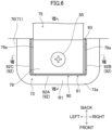
FIG. 8 is a cross-sectional view taken along line IIIV-IIIV shown inFIG. 6 . -
FIG. 9 is a view corresponding toFIG. 8 and illustrating a first variation. -
FIG. 10 is a view corresponding toFIG. 8 and illustrating a second variation. -
FIG. 11 is a view corresponding toFIG. 8 and illustrating a third variation. -
FIG. 12 is a view corresponding toFIG. 8 and illustrating another embodiment. - Embodiments of the present disclosure will be described in detail below with reference to the drawings. The present disclosure is not limited to the embodiments shown below, and various changes can be made within the scope without departing from the technical concept of the present disclosure. Since each of the drawings is intended to illustrate the present disclosure conceptually, dimensions, ratios, or numbers may be exaggerated or simplified as necessary for the sake of ease of understanding.
- As illustrated in
FIG. 1 , an air conditioner (10) includes an outdoor unit (20) and an indoor unit (30). Each of the outdoor unit (20) and the indoor unit (30) is a component unit forming the air conditioner (10). - The outdoor unit (20) and the indoor unit (30) are connected to each other through a pair of connection pipes (12). In the air conditioner (10), the outdoor unit (20), the indoor unit (30), and the connection pipes (12) form a refrigerant circuit (11) that performs a vapor compression refrigeration cycle.
- The outdoor unit (20) is placed outside. The outdoor unit (20) has a compressor (21), a four-way switching valve (22), an outdoor heat exchanger (23), an outdoor fan (25), an expansion valve (24), a liquid-side shutoff valve (26), and a gas-side shutoff valve (27).
- The compressor (21) is, for example, a hermetic scroll or hermetic rotary compressor. The compressor (21) sucks and compresses a low-pressure refrigerant, and discharges the refrigerant compressed to high pressure (high-pressure refrigerant).
- The four-way switching valve (22) is a valve for changing the flow of refrigerant in the refrigerant circuit (11). The four-way switching valve (22) switches between a first state indicated by solid lines in
FIG. 1 and a second state indicated by broken lines inFIG. 2 . In the first state, the high-pressure refrigerant discharged from the compressor (21) is sent to the outdoor heat exchanger (23), and the low-pressure refrigerant flowed from the indoor unit (30) is sent to the compressor (21). In the second state, the high-pressure refrigerant discharged from the compressor (21) is sent to the indoor unit (30), and the low-pressure refrigerant passed through the outdoor heat exchanger (23) is sent to the compressor (21). - The outdoor heat exchanger (23) is a heat exchanger that allows heat exchange between the refrigerant and outdoor air. The outdoor heat exchanger (23) is, for example, a fin-and-tube heat exchanger. The outdoor fan (25) is a fan for supplying the outdoor air to the outdoor heat exchanger (23). The expansion valve (24) is an electric expansion valve having a variable opening degree.
- The indoor unit (30) is placed in an indoor space which is a space to be air-conditioned. The indoor unit (30) has an indoor heat exchanger (65) and an indoor fan (50).
- As illustrated in
FIG. 2 , the indoor unit (30) of this embodiment is a ceiling-embedded indoor unit. As illustrated inFIGS. 3 and4 , the indoor unit (30) includes a casing (35), the indoor fan (50), the indoor heat exchanger (65), a drain pan (55), and a bell mouth (52). - The casing (35) includes a casing body (36) and a decorative panel (40). The casing (35) houses the indoor fan (50), the indoor heat exchanger (65), the drain pan (55), and the bell mouth (52).
- The casing body (36) is a member having a generally rectangular parallelepiped box-like shape with an open bottom. The casing body (36) has a generally flat plate-shaped top panel (36a), and side plates (36b) extending downward from a peripheral portion of the top panel (36a).
- As illustrated in
FIG. 4 , the indoor fan (50) is a so-called turbo fan. The indoor fan (50) discharges air sucked from below outward in a radial direction. The indoor fan (50) is disposed at the center in the casing body (36). The indoor fan (50) is driven by an indoor fan motor (51). The indoor fan motor (51) is fixed to a center portion of the top panel (36a). - The bell mouth (52) is disposed below the indoor fan (50). The bell mouth (52) is a member that guides the air flowed into the casing (35) to the indoor fan (50). The bell mouth (52) and the drain pan (55) divide the internal space of the casing (35) into a primary space (37a) located on the inlet side of the indoor fan (50) and a secondary space (37b) located on the outlet side of the indoor fan (50).
- The indoor heat exchanger (65) is a so-called cross-fin-type fin-and-tube heat exchanger. As illustrated in
FIG. 3 , the indoor heat exchanger (65) is formed in a rectangular tubular shape in plan view and is arranged to surround the indoor fan (50). The indoor heat exchanger (65) is disposed in the secondary space (37b). The indoor heat exchanger (65) allows the air passing from the inside to the outside to exchange heat with the refrigerant in the refrigerant circuit. - The indoor heat exchanger (65) includes a plurality of fins (67) and a heat transfer tube (66) penetrating the fins (67) in the thickness direction. The refrigerant flows through the heat transfer tube (66). The fins (67) are heat transfer members that promote the heat exchange between the refrigerant and the air.
- The drain pan (55) is a member made of so-called polystyrene foam. As illustrated in
FIG. 4 , the drain pan (55) is disposed to close the lower end of the casing body (36). The drain pan (55) has an upper surface provided with a water receiving groove (56) extending along the lower end of the indoor heat exchanger (65). The water receiving groove (56) receives a lower end portion of the indoor heat exchanger (65). The water receiving groove (56) receives drain water generated in the indoor heat exchanger (65). - As illustrated in
FIG. 2 , the drain pan (55) is provided with four main outlet paths (57) and four auxiliary outlet paths (58). The main outlet paths (57) and the auxiliary outlet paths (58) are passages through which the air that has passed through the indoor heat exchanger (65) flows, and vertically penetrate the drain pan (55). - The main outlet paths (57) are through holes each having an elongated rectangular cross section. The main outlet paths (57) are arranged along the four sides of the casing body (36), respectively. The auxiliary outlet paths (58) are through holes each having a slightly-curved rectangular cross section. The auxiliary outlet paths (58) are arranged at the four corners of the casing body (36), respectively.
- The decorative panel (40) is a resin member formed in a thick rectangular plate shape. A lower portion of the decorative panel (40) is in a square shape slightly larger than the top panel (36a) of the casing body (36). The decorative panel (40) is disposed to cover the lower end of the casing body (36). A lower surface of the decorative panel (40) is exposed to the indoor space.
- As illustrated in
FIGS. 2 and4 , the decorative panel (40) has a square inlet (41) formed in a center portion. The inlet (41) penetrates the decorative panel (40) in the vertical direction to communicate with the primary space (37a) in the casing (35). The inlet (41) is provided with a grid-like intake grille (45). A filter (46) is disposed above the intake grille (45). - The decorative panel (40) includes a substantially rectangular loop-shaped outlet (44) surrounding the inlet (41). As illustrated in
FIG. 2 , the outlet (44) is divided into four main outlet openings (42) and four auxiliary outlet openings (43). - The main outlet openings (42) are elongated rectangular openings. The main outlet openings (42) are arranged along the four sides of the decorative panel (40), respectively. The main outlet openings (42) of the decorative panel (40) correspond to the main outlet paths (57) of the drain pan (55) on a one-on-one basis. Each main outlet opening (42) communicates with a corresponding one of the main outlet paths (57). Each main outlet opening (42) is provided with an airflow direction adjusting flap (47).
- The auxiliary outlet openings (43) are quarter circular arc-shaped openings. The auxiliary outlet openings (43) are arranged at the four corners of the decorative panel (40), respectively. The auxiliary outlet openings (43) of the decorative panel (40) correspond to the auxiliary outlet paths (58) of the drain pan (55) on a one-on-one basis. Each auxiliary outlet opening (43) communicates with a corresponding one of the auxiliary outlet paths (58).
- The air conditioner (10) selectively performs cooling operation and heating operation.
- In the cooling operation, the four-way switching valve (22) is set to the first state, and the refrigerant circulates through the refrigerant circuit (11). In the refrigerant circuit (11), the outdoor heat exchanger (23) functions as a radiator, and the indoor heat exchanger (31) functions as an evaporator. The indoor unit (30) cools the air sucked from the indoor space in the indoor heat exchanger (31), and blows the cooled air into the indoor space.
- In the heating operation, the four-way switching valve (22) is set to the second state, and the refrigerant circulates through the refrigerant circuit (11). In the refrigerant circuit (11), the indoor heat exchanger (31) functions as a radiator, and the outdoor heat exchanger (23) functions as an evaporator. The indoor unit (30) heats the air sucked from the indoor space in the indoor heat exchanger (31), and blows the heated air into the indoor space.
- The indoor fan (50) rotates during the operation of the indoor unit. When the indoor fan (50) rotates, the indoor air in the indoor space flows into the primary space (37a) in the casing (35) through the inlet (41). The air flowed into the primary space (37a) is sucked by the indoor fan (50) and discharged into the secondary space (37b).
- The air flowed into the secondary space (37b) is cooled or heated while passing through the indoor heat exchanger (65), and then flows separately into the four main outlet paths (57) and the four auxiliary outlet paths (58). The air flowed into the main outlet paths (57) is discharged to the indoor space through the main outlet openings (42). The air flowed into the auxiliary outlet paths (58) is discharged to the indoor space through the auxiliary outlet openings (43).
- The indoor unit (30) of the air conditioner (10) of this embodiment includes a heat insulating case (70), a support (75), a fastening member (85), and a preventing member (90). The heat insulating case (70) is provided inside the casing (35) of the indoor unit (30). The support (75) is fixed to the top panel (36a) of the casing (35) and supports the indoor heat exchanger (65) as a heat exchanger. The preventing member (90) prevents condensation water from traveling to the support (75). Details of these components will be described with reference to
FIGS. 4 to 8 . In the following description, terms implying any directions such as "upper," "lower," "right," "left," "front," and "rear" are used herein relative to the directions indicated by arrows inFIG. 5 in principle. - As illustrated in
FIG. 4 , the heat insulating case (70) covers an inner surface of the casing body (36). The heat insulating case (70) is a heat insulating member made of so-called polystyrene foam. The heat insulating case (70) is a rectangular parallelepiped box-shaped member with an open bottom. The heat insulating case (70) includes a top heat insulating portion (71) formed on the inner surface of the top panel (36a), and side heat insulating portions (72) respectively formed on the inner surfaces of the side plates (36b). The heat insulating case (70) reduces the generation of condensation water on the inner surface of the top panel (36a). Specifically, the heat insulating case (70) covers the inner surface of the top panel (36a) not to expose the inner surface to the space inside the casing (35). This keeps the air from being cooled to the dew-point temperature or lower on the inner surface of the top panel (36a), reducing the generation of the condensation water on the inner surface. - The heat insulating case (70) has an opening (73) for fixing the support (75) to the top panel (36a). Specifically, the top heat insulating portion (71) of the heat insulating case (70) has the opening (73) corresponding to a portion to which the support (75) is fixed. The indoor unit (30) of this example includes a plurality of supports (75). The heat insulating case (70) has a plurality of openings (73) respectively corresponding to the plurality of supports (75).
- The openings (73) expose the inner surface of the top panel (36a) to the space inside the casing (35). Thus, with the heat insulating case (70) attached to the inside of the casing (35), the supports (75) can be fixed to the top panel (36a) through the openings (73).
- As illustrated in
FIG. 5 , the supports (75) are arranged inside the indoor heat exchanger (65) in the casing (35). In other words, the supports (75) are arranged in the primary space (37a) upstream of the indoor heat exchanger (65) in the air flow. Although not shown, the indoor unit (30) of this example includes three supports (75). The supports (75) are provided on different sides of the indoor heat exchanger (65). - Each support (75) is formed in a plate shape extending in the vertical direction. The support (75) is formed by folding a sheet metal. The support (75) includes a main plate (76), a lower plate (77), a vertical plate (78), and an upper plate (79).
- The main plate (76) extends in the vertical direction along the inner surface of the indoor heat exchanger (65). The main plate (76) is formed in a vertically elongated rectangular plate shape. First raised portions (76a) protruding forward are formed on the left and right sides of the main plate (76).
- The lower plate (77) extends rearward from the lower end of the main plate (76) along the lower surface of the indoor heat exchanger (65). The vertical plate (78) extends upward from the rear end of the lower plate (77) along the outer surface of the indoor heat exchanger (65). The indoor heat exchanger (65) is held between the main plate (76), the lower plate (77), and the vertical plate (78). In other words, the support (75) includes a hook portion that supports the indoor heat exchanger (65) from below.
- The upper plate (79) extends forward from the upper end of the main plate (76). The upper plate (79) extends in a direction away from the indoor heat exchanger (65). The upper plate (79) serves as a fixing part for fixing the support (75) to the top panel (36a). The upper plate (79) is formed in a rectangular shape in plan view. Second raised portions (79a) protrude downward from the front end, right end, and left end of the upper plate (79).
- The opening (73) is formed in the heat insulating case (70) at a position corresponding to the upper plate (79). In other words, the upper plate (79) is located inside the opening (73).
- The upper plate (79) is provided with a first fastening hole (80) in which the fastening member (85) is inserted. The first fastening hole (80) penetrates the upper plate (79) in the thickness direction. The first fastening hole (80) is formed in a circular shape in plan view.
- The fastening member (85) is a component for fixing the support (75) to the top panel (36a). The fastening member (85) may be a screw, or a bolt and a nut. The upper plate (79) of the support (75) is fixed to the top panel (36a) by tightening the fastening member (85).
- The casing (35) and the support (75) are made of an iron-based metallic material. In contrast, the heat transfer tube (66) and fins (67) of the indoor heat exchanger (65) are made of an aluminum-based metallic material. Thus, the ionization tendency of the heat transfer tube (66) is higher than that of the top panel (36a). In addition, the ionization tendency of the heat transfer tube (66) is higher than that of the support (75). The ionization tendency of the support (75) is equal to or lower than that of the top panel (36a). The ionization tendency of the fastening member (85) is equal to or lower than that of the top panel (36a). The materials of these components are merely examples, and other materials can be used.
- The above-described heat insulating case (70) is designed to have the opening (73) slightly larger than the upper plate (79) in plan view in consideration of manufacturing and assembly errors of the heat insulating case (70). If the upper plate (79) and the opening (73) are misaligned due to these errors, the fixing of the upper plate (79) to the top panel (36a) may possibly be failed.
- If the opening (73) is formed to be slightly larger in this way, a region of the inner surface of the top panel (36a) appears between a first edge (73a) defined by the opening (73) and the upper plate (79) (hereinafter referred to as a first region (R1)). Thus, the first region (R1) of the top panel (36a) is exposed to the internal space of the casing (35), and the air may be cooled on the first region (R1), generating the condensation water.
- As described above, the heat transfer tube (66) is made of a material having a higher ionization tendency than the top panel (36a). Thus, if the condensation water travels from the first region (R1) to the heat transfer tube (66) through the support (75), the heat transfer tube (66) may be electrically corroded.
- Considering this issue, the indoor unit (30) of this embodiment is provided with a preventing member (90) that prevents the condensation water from traveling from the first region (R1) to the support (75). The preventing member (90) prevents the condensation water generated in the first region (R1) from traveling to the support (75).
- The preventing member (90) is made of a resin material. The preventing member (90) is preferably made of a heat insulating material. The preventing member (90) has higher hardness than the heat insulating case (70).
- As illustrated in
FIGS. 6 to 8 , the preventing member (90) is arranged inside the opening (73) of the heat insulating case (70). The preventing member (90) includes a side portion (91) located in the first region (R1) of the top panel (36a) and an intermediate portion (95) located between the top panel (36a) and the upper plate (79). - The side portion (91) of the preventing member (90) has projections (92) and a base (93). The preventing member (90) of this embodiment includes a plurality of projections (92) surrounding the upper plate (79). The projections (92) are provided one by one at positions corresponding to the sides of the upper plate (79). Each projection (92) is in the form of a plate. The projections (92) extend downward from the first region (R1).
- Specifically, the projections (92) of this embodiment include a first projection (92A), a second projection (92B), and a third projection (92C). The first region (R1) of this embodiment has relatively large area portions in front of and on the right and left of the upper plate (79). In this embodiment, the three projections (92) are provided to correspond to these portions. The first projection (92A) is located in front of the upper plate (79). The first projection (92A) extends in the left-right direction along the front side of the upper plate (79). The second projection (92B) is located on the right of the upper plate (79). The second projection (92B) extends in the front-back direction along the right side of the upper plate (79). The third projection (92C) is located on the left of the upper plate (79). The third projection (92C) extends in the front-back direction along the left side of the upper plate (79).
- The base (93) is shorter than the projection (92) in the vertical direction. The base (93) is formed between the projections (92) and the upper plate (79) in plan view. In other words, the base (93) is formed to extend over the projections (92) and the upper plate (79) in plan view.
- The intermediate portion (95) is interposed between the top panel (36a) and the upper plate (79). The intermediate portion (95) covers a region of the inner surface of the top panel (36a) located above (on the back side of) the upper plate (79). The intermediate portion (95) is rectangular in plan view. The intermediate portion (95) has higher hardness than the heat insulating case (70). The intermediate portion (95) has a second fastening hole (96) through which the fastening member (85) is inserted. The second fastening hole (96) is formed in a circular shape in plan view. The center of the second fastening hole (96) and the center of the first fastening hole (80) substantially coincide with each other. The second fastening hole (96) has a smaller inner diameter than the first fastening hole (80).
- The indoor heat exchanger (65) is supported on the top panel (36a) by the following procedure.
- The heat insulating case (70) is attached to the inside of the casing (35). Then, the indoor heat exchanger (65) is hooked on the hook portion of the support (75). Then, the preventing member (90) and the upper plate (79) of the support (75) are positioned in the opening (73) of the heat insulating case (70). The intermediate portion (95) of the preventing member (90) is sandwiched between the upper plate (79) and the top panel (36a), and the fastening member (85) is tightened to the top panel (36a) with the axial centers of the first fastening hole (80) and the second fastening hole (96) aligned with each other. Thus, the preventing member (90) and the support (75) are fixed to the top panel (36a) with the fastening member (85).
- The preventing member (90) prevents the condensation water from traveling to the support (75) from the first region (R1) of the inner surface of the top panel (36a) between the first edge (73a) of the opening (73) and the upper plate (79). Specifically, the preventing member (90) prevents the condensation water generated in the first region (R1) from traveling to the support (75). This keeps the condensation water generated in the first region (R1) from traveling to the aluminum heat transfer tube (66) through the support (75), reducing electrical corrosion of the heat transfer tube (66).
- More specifically, the preventing member (90) includes the projections (92) extending downward from the first region (R1). Thus, if the condensation water is generated in a portion of the first region (R1) located across the side portion (91) from the upper plate (79), the projections (92) can prevent the condensation water from reaching the upper plate (79). Specifically, the condensation water falls downward along the side surfaces of the projections (92), and can be prevented from moving to the upper plate (79). This can keep the condensation water generated in the first region (R1) from traveling to the support (75).
- The preventing member (90) includes the projections (92) and the base (93) that is shorter than the projections (92) and that is formed between the projections (92) and the upper plate (79).
- The projections (92) can prevent the condensation water generated in the first region (R1) from reaching the upper plate (79). In addition, the base (93) can reduce the generation of the condensation water around the upper plate (79). This can further keep the condensation water from traveling from the first region (R1) to the support (75).
- The preventing member (90) includes the intermediate portion (95) located between the top panel (36a) and the upper plate (79). The intermediate portion (95) covers a portion of the inner surface of the top panel (36a) located on the back side of the upper plate (79). Thus, the generation of the condensation water in this portion can be reduced. This can keep the condensation water from traveling to the support (75) through the second fastening hole (96) and the first fastening hole (80).
- The base (93) and the intermediate portion (95) are formed continuously and integrally, and can simultaneously reduce the generation of the condensation water in part of the first region (R1) ranging from the vicinity of the upper plate (79) to the back side of the upper plate (79).
- The indoor unit (30) includes the fastening member (85) for fastening the upper plate (79) to the top panel (36a) together with the intermediate portion (95). Thus, tightening the fastening member (85) can fix the preventing member (90) and the support (75) to the top panel (36a) at the same time. In addition, the preventing member (90) can be easily aligned with the upper plate (79).
- The intermediate portion (95) has higher hardness than the heat insulating case (70). Thus, the tightening of the fastening member (85) causes less damage to the intermediate portion (95) or the preventing member (90). This can reduce the generation of the condensation water on the back side of the upper plate (79) due to the damage to the intermediate portion (95).
- The preventing member (90) is made of a resin material. This can reduce electrical corrosion of the preventing member (90) caused by the condensation water. The preventing member (90) made of a heat insulating material can reduce the generation of the condensation water on part of the top panel (36a) covered with the preventing member (90).
- The above embodiment may be modified as follows. Differences from the above embodiment will be described below.
- As illustrated in
FIG. 9 , a preventing member (90) of the first variation is an auxiliary heat insulating member (98). The auxiliary heat insulating member (98) is a component separate from the heat insulating case (70). The auxiliary heat insulating member (98) is arranged inside the opening (73) to cover the first region (R1). The auxiliary heat insulating member (98) may be made of the same material as the heat insulating case (70) or may be made of a different material. The auxiliary heat insulating member (98) may cover the whole of the first region (R1) or may cover part of the first region (R1). The auxiliary heat insulating member (98) reduces the generation of the condensation water in the first region (R1), keeping the condensation water from traveling from the first region (R1) to the support (75). This can reduce electrical corrosion of the heat transfer tube (66). - The auxiliary heat insulating member (98) has a smaller volume than the heat insulating case (70). Thus, the auxiliary heat insulating member (98) causes less manufacturing and assembly errors than the heat insulating case (70). This allows the auxiliary heat insulating member (98) to be accurately arranged in the opening (73).
- As illustrated in
FIG. 10 , the second variation further includes a resin fixing piece (86) added to the configuration of the above embodiment. The fixing piece (86) is a so-called washer made of resin. The fixing piece (86) is arranged between a head (85a) of the fastening member (85) and the upper plate (79). The fixing piece (86) has a hole through which a threaded portion (85b) of the fastening member (85) is inserted. The fixing piece (86) is fixed to the fastening member (85) to close a clearance (C) between a second edge (80a) defined by the first fastening hole (80) of the upper plate (79) and the threaded portion (85b) of the fastening member (85). The fixing piece (86) prevents the condensation water generated on the top panel (36a) from traveling to the support (75) through the clearance (C). This can reduce electrical corrosion of the heat transfer tube (66). The fixing piece (86), which is made of the resin material, can also be less likely to corrode. - As illustrated in
FIG. 11 , the third variation includes a cutout (95a) formed in the center of the intermediate portion (95) of the preventing member (90) of the embodiment. The cutout (95a) is a circular opening that enlarges the inner diameter of the second fastening hole (96) of the embodiment. In the third variation, the upper plate (79) and the top panel (36a) are configured to be in contact with each other through the cutout (95a). Specifically, in this example schematically shown inFIG. 11 , the center of the upper plate (79) is pressed against the top panel (36a) when the fastening member (85) is tightened. Thus, the second edge (80a) of the upper plate (79) makes contact with the top panel (36a). The top panel (36a) is grounded. Bringing the top panel (36a) and the support (75) into contact with each other can ground the top panel (36a), the support (75), and the heat exchanger (65). This can reduce sparks and electric shock to workers due to charging of the indoor heat exchanger (65). - The embodiment and variations may be modified as follows.
- The support (75) and the preventing member (90) may be provided in the outdoor unit (20) as a component unit. In this case, the support (75) supports the outdoor heat exchanger (23) as a heat exchanger.
- The support (75) may be placed outside the indoor heat exchanger (65). In other words, the support (75) may be arranged in the secondary space (37b) downstream of the indoor heat exchanger (65) in the air flow.
- The preventing member (90) may be made of a metallic material. In this case, the ionization tendency of the preventing member (90) is preferably equal to or lower than that of the top panel (36a). The potential difference between the preventing member (90) and the indoor heat exchanger (65) is preferably smaller than the potential difference between the top panel (36a) and the indoor heat exchanger (65).
- The preventing member (90) may have a single projection (92), two projections (92), or four or more projections (92). When the four projections (92) are provided, the projections (92) are preferably arranged one by one in correspondence with the four sides of the upper plate (79).
- As illustrated in
FIG. 12 , the projection (92) of the embodiment may extend to reach the upper plate (79). The preventing member (90) of this configuration does not have the base (93) shorter than the projection (92) of the above-described embodiment. The projection (92) has the same height in every part. In this configuration, an area of the first region (R1) covered by the projection (92) is larger, and an area of the first region (R1) exposed to the space inside the casing (35) is smaller. This can reduce the generation of the condensation water in the first region (R1). - While the embodiments and the variations thereof have been described above, it will be understood that various changes in form and details may be made without departing from the spirit and scope of the claims. The elements according to the embodiment, the variations thereof, and the other embodiments may be combined and replaced with each other.
- The ordinal numbers such as "first," "second," and "third" described above are used to distinguish the terms to which these expressions are given, and do not limit the number and order of the terms.
- As can be seen from the foregoing description, the present disclosure is useful for an air conditioner and a component unit.
-
- 10
- Air Conditioning Device
- 35
- Casing
- 36a
- Top Panel
- 65
- Indoor Heat Exchanger (Heat Exchanger)
- 67
- Heat Transfer Tube
- 70
- Heat Insulating Case (Heat Insulating Member)
- 73
- Opening
- 73a
- First Edge
- 75
- Support
- 79
- Upper Part (Fixing Part)
- 80
- First Fastening Hole (Fastening Hole)
- 80a
- Second Edge
- 85
- Fastening Member
- 86
- Fixing Piece
- 90
- Preventing Member
- 92
- Projection
- 93
- Base
- 95
- Intermediate Portion
- 95a
- Cutout
- 98
- Auxiliary Heat Insulating Member
- C
- Clearance
- R1
- First Region
Claims (14)
- A component unit of an air conditioner, the component unit comprising:a casing (35) having a top panel (36a) made of a metallic material;a heat exchanger (65) arranged in the casing (35) and having a heat transfer tube (66) made of a material having a higher ionization tendency than the top panel (36a);a heat insulating member (70) configured to cover an inner surface of the top panel (36a) and having an opening (73);a support (75) configured to support the heat exchanger (65) and having a fixing part (79) fixed to an inner surface of the top panel (36a) inside the opening (73); anda preventing member (90) configured to prevent condensation water from traveling to the support (75) from a first region (73a) of the inner surface of the top panel (36a) between a first region (R1) defined by the opening (73) and the fixing part (79).
- The component unit of claim 1, wherein
the preventing member (90) is configured to prevent condensation water generated in the first region (R1) from traveling to the support (75). - The component unit of claim 2, wherein
the preventing member (90) includes a projection (92) extending downward from the first region (R1). - The component unit of claim 3, wherein
the preventing member (90) includes the projection (92) and a base (93) that is shorter than the projection (92) and that is formed between the projection (92) and the fixing part (79). - The component unit of claim 3, wherein
the projection (92) extends to reach the fixing part (79). - The component unit of claim 1, wherein
the preventing member (90) is configured to eliminate or reduce the generation of the condensation water in the first region (R1) to prevent the condensation water from traveling from the first region (R1) to the support (75). - The component unit of claim 6, wherein
the preventing member (90) includes an auxiliary heat insulating member (98) that is formed separately from the heat insulating member (70) and that covers the first region (R1). - The component unit of any one of claims 1 to 7, wherein
the preventing member (90) includes an intermediate portion (95) located between the top panel (36a) and the fixing part (79). - The component unit of claim 8, further comprising:
a fastening member (85) configured to fasten the fixing part (79) to the top panel (36a) together with the intermediate portion (95). - The component unit of claim 9, wherein
the intermediate portion (95) has higher hardness than the heat insulating member (70). - The component unit of claim 9 or 10, whereinthe fixing part (79) is provided with a fastening hole (80) through which the fastening member (85) passes, andthe component unit includes a resin fixing piece (86) arranged under the fixing part (79) and fixed to the fastening member (85) to close a clearance (C) between a second edge (80a) defined by the fastening hole (80) and the fastening member (85).
- The component unit of any one of claims 8 to 11, whereinthe intermediate portion (95) is provided with a cutout (95a), andthe fixing part (79) and the top panel (36a) are configured to be in contact with each other through the cutout (95a).
- The component unit of any one of claims 1 to 12, wherein
the preventing member (90) is made of a resin material. - An air conditioner comprising the component unit according to any one of claims 1 to 13.
Applications Claiming Priority (2)
| Application Number | Priority Date | Filing Date | Title |
|---|---|---|---|
| JP2022148302A JP7460925B1 (en) | 2022-09-16 | 2022-09-16 | Air conditioning equipment and component units |
| PCT/JP2023/029991 WO2024057833A1 (en) | 2022-09-16 | 2023-08-21 | Air conditioning device and component unit |
Publications (2)
| Publication Number | Publication Date |
|---|---|
| EP4560218A1 true EP4560218A1 (en) | 2025-05-28 |
| EP4560218A4 EP4560218A4 (en) | 2025-11-12 |
Family
ID=90274965
Family Applications (1)
| Application Number | Title | Priority Date | Filing Date |
|---|---|---|---|
| EP23865191.3A Pending EP4560218A4 (en) | 2022-09-16 | 2023-08-21 | Air conditioning device and component unit |
Country Status (5)
| Country | Link |
|---|---|
| US (1) | US20250198648A1 (en) |
| EP (1) | EP4560218A4 (en) |
| JP (1) | JP7460925B1 (en) |
| CN (1) | CN119731489B (en) |
| WO (1) | WO2024057833A1 (en) |
Family Cites Families (18)
| Publication number | Priority date | Publication date | Assignee | Title |
|---|---|---|---|---|
| JPS59113127U (en) * | 1983-01-19 | 1984-07-31 | 三洋電機株式会社 | air conditioner |
| JPS59132027U (en) * | 1983-02-24 | 1984-09-04 | ダイキン工業株式会社 | air conditioner |
| JPS6453816U (en) * | 1987-09-30 | 1989-04-03 | ||
| JP3015648B2 (en) * | 1993-12-28 | 2000-03-06 | 三洋電機株式会社 | Air conditioner |
| TW384374B (en) * | 1996-10-03 | 2000-03-11 | Toshiba Corp | Indoor unit of air-conditioner |
| JP2004156886A (en) * | 2002-11-08 | 2004-06-03 | Mitsubishi Heavy Ind Ltd | Air-conditioning indoor unit and ceiling embedded air conditioner |
| KR20070099224A (en) * | 2006-04-04 | 2007-10-09 | 엘지전자 주식회사 | Ventilation Interlocking Air Clean System |
| JP5321413B2 (en) * | 2009-10-29 | 2013-10-23 | ダイキン工業株式会社 | Air conditioner |
| JP2013015296A (en) * | 2011-07-06 | 2013-01-24 | Panasonic Corp | Air conditioner |
| JP5858851B2 (en) * | 2012-04-03 | 2016-02-10 | 三菱電機株式会社 | Air conditioner indoor unit |
| JP6149494B2 (en) * | 2013-04-30 | 2017-06-21 | ダイキン工業株式会社 | Indoor unit for decorative panel and air conditioner |
| JP2017058098A (en) * | 2015-09-18 | 2017-03-23 | 東芝キヤリア株式会社 | Refrigeration cycle apparatus |
| JP6481577B2 (en) * | 2015-09-24 | 2019-03-13 | 株式会社富士通ゼネラル | Embedded ceiling air conditioner |
| JP6673318B2 (en) | 2017-12-05 | 2020-03-25 | ダイキン工業株式会社 | air conditioner |
| JP6407466B1 (en) * | 2018-04-19 | 2018-10-17 | 株式会社 エコファクトリー | Outside air conditioner and ventilation system |
| KR102203437B1 (en) * | 2018-11-16 | 2021-01-14 | 엘지전자 주식회사 | Indoor Unit for Air Conditioner |
| CN210891906U (en) * | 2019-02-28 | 2020-06-30 | 三菱电机株式会社 | Indoor unit of air conditioner and air conditioner |
| WO2020217447A1 (en) * | 2019-04-26 | 2020-10-29 | 日立ジョンソンコントロールズ空調株式会社 | Air conditioner |
-
2022
- 2022-09-16 JP JP2022148302A patent/JP7460925B1/en active Active
-
2023
- 2023-08-21 EP EP23865191.3A patent/EP4560218A4/en active Pending
- 2023-08-21 WO PCT/JP2023/029991 patent/WO2024057833A1/en not_active Ceased
- 2023-08-21 CN CN202380060262.4A patent/CN119731489B/en active Active
-
2025
- 2025-02-28 US US19/066,425 patent/US20250198648A1/en active Pending
Also Published As
| Publication number | Publication date |
|---|---|
| CN119731489B (en) | 2025-11-21 |
| WO2024057833A1 (en) | 2024-03-21 |
| CN119731489A (en) | 2025-03-28 |
| US20250198648A1 (en) | 2025-06-19 |
| JP7460925B1 (en) | 2024-04-03 |
| EP4560218A4 (en) | 2025-11-12 |
| JP2024051181A (en) | 2024-04-11 |
Similar Documents
| Publication | Publication Date | Title |
|---|---|---|
| US10782035B2 (en) | Heat exchanger assembly and outdoor unit of refrigerating apparatus | |
| EP3260785B1 (en) | Outdoor unit | |
| US9404669B2 (en) | Application of electric heat coil in fan unit | |
| US11859859B2 (en) | Outdoor unit for air-conditioning apparatus | |
| CN220669585U (en) | Air conditioner | |
| US20150316279A1 (en) | Outdoor unit for air-conditioning apparatus | |
| US20250224188A1 (en) | Component unit of air conditioning apparatus | |
| JP2000046375A (en) | Outdoor unit and air conditioner | |
| US20250198648A1 (en) | Air conditioner and component unit | |
| JP7386964B2 (en) | Air conditioner outdoor unit | |
| US7658085B2 (en) | Monolithic air conditioner | |
| EP4534927B1 (en) | Air conditioner constituent unit and air conditioner | |
| US20070044495A1 (en) | Monolithic air conditioner | |
| JP7862719B2 (en) | Heat exchanger, and indoor unit of an air conditioning system equipped with the heat exchanger | |
| EP4343251A1 (en) | Heat exchanger and outdoor unit | |
| US20250116420A1 (en) | Coil guard for an hvac system | |
| CN215295139U (en) | Indoor air conditioner | |
| US20070130987A1 (en) | Condensing unit and cooling apparatus equipped with condensing unit | |
| JP7346181B2 (en) | heat source device | |
| WO2026033585A1 (en) | Outdoor machine and refrigeration cycle device | |
| KR100308382B1 (en) | Air conditioner outdoor unit | |
| JP2023173582A (en) | Air conditioning indoor unit and air conditioner | |
| JP3363093B2 (en) | Exhaust heat structure of condenser | |
| KR100982857B1 (en) | Front suction and discharge type outdoor unit for air-conditioner | |
| JP2023104046A (en) | Outdoor unit of air conditioner |
Legal Events
| Date | Code | Title | Description |
|---|---|---|---|
| STAA | Information on the status of an ep patent application or granted ep patent |
Free format text: STATUS: THE INTERNATIONAL PUBLICATION HAS BEEN MADE |
|
| PUAI | Public reference made under article 153(3) epc to a published international application that has entered the european phase |
Free format text: ORIGINAL CODE: 0009012 |
|
| STAA | Information on the status of an ep patent application or granted ep patent |
Free format text: STATUS: REQUEST FOR EXAMINATION WAS MADE |
|
| 17P | Request for examination filed |
Effective date: 20250219 |
|
| AK | Designated contracting states |
Kind code of ref document: A1 Designated state(s): AL AT BE BG CH CY CZ DE DK EE ES FI FR GB GR HR HU IE IS IT LI LT LU LV MC ME MK MT NL NO PL PT RO RS SE SI SK SM TR |
|
| P01 | Opt-out of the competence of the unified patent court (upc) registered |
Free format text: CASE NUMBER: UPC_APP_3795_4560218/2025 Effective date: 20250820 |
|
| A4 | Supplementary search report drawn up and despatched |
Effective date: 20251015 |
|
| RIC1 | Information provided on ipc code assigned before grant |
Ipc: F24F 13/22 20060101AFI20251009BHEP Ipc: F24F 1/0047 20190101ALI20251009BHEP Ipc: F24F 13/20 20060101ALI20251009BHEP Ipc: F24F 1/0063 20190101ALI20251009BHEP |
|
| DAV | Request for validation of the european patent (deleted) | ||
| DAX | Request for extension of the european patent (deleted) | ||
| GRAP | Despatch of communication of intention to grant a patent |
Free format text: ORIGINAL CODE: EPIDOSNIGR1 |
|
| STAA | Information on the status of an ep patent application or granted ep patent |
Free format text: STATUS: GRANT OF PATENT IS INTENDED |
|
| RIC1 | Information provided on ipc code assigned before grant |
Ipc: F24F 13/22 20060101AFI20260706BHEP Ipc: F24F 1/0047 20190101ALI20260706BHEP Ipc: F24F 13/20 20060101ALI20260706BHEP Ipc: F24F 1/0063 20190101ALI20260706BHEP |