EP4560216A1 - Air-conditioning device - Google Patents
Air-conditioning device Download PDFInfo
- Publication number
- EP4560216A1 EP4560216A1 EP23842910.4A EP23842910A EP4560216A1 EP 4560216 A1 EP4560216 A1 EP 4560216A1 EP 23842910 A EP23842910 A EP 23842910A EP 4560216 A1 EP4560216 A1 EP 4560216A1
- Authority
- EP
- European Patent Office
- Prior art keywords
- outdoor unit
- outdoor
- refrigerant circuit
- refrigerant
- circuit state
- Prior art date
- Legal status (The legal status is an assumption and is not a legal conclusion. Google has not performed a legal analysis and makes no representation as to the accuracy of the status listed.)
- Pending
Links
Images




Classifications
-
- F—MECHANICAL ENGINEERING; LIGHTING; HEATING; WEAPONS; BLASTING
- F24—HEATING; RANGES; VENTILATING
- F24F—AIR-CONDITIONING; AIR-HUMIDIFICATION; VENTILATION; USE OF AIR CURRENTS FOR SCREENING
- F24F11/00—Control or safety arrangements
- F24F11/30—Control or safety arrangements for purposes related to the operation of the system, e.g. for safety or monitoring
- F24F11/49—Control or safety arrangements for purposes related to the operation of the system, e.g. for safety or monitoring ensuring correct operation, e.g. by trial operation or configuration checks
-
- F—MECHANICAL ENGINEERING; LIGHTING; HEATING; WEAPONS; BLASTING
- F24—HEATING; RANGES; VENTILATING
- F24F—AIR-CONDITIONING; AIR-HUMIDIFICATION; VENTILATION; USE OF AIR CURRENTS FOR SCREENING
- F24F11/00—Control or safety arrangements
- F24F11/30—Control or safety arrangements for purposes related to the operation of the system, e.g. for safety or monitoring
- F24F11/46—Improving electric energy efficiency or saving
-
- F—MECHANICAL ENGINEERING; LIGHTING; HEATING; WEAPONS; BLASTING
- F24—HEATING; RANGES; VENTILATING
- F24F—AIR-CONDITIONING; AIR-HUMIDIFICATION; VENTILATION; USE OF AIR CURRENTS FOR SCREENING
- F24F11/00—Control or safety arrangements
- F24F11/50—Control or safety arrangements characterised by user interfaces or communication
- F24F11/56—Remote control
-
- F—MECHANICAL ENGINEERING; LIGHTING; HEATING; WEAPONS; BLASTING
- F24—HEATING; RANGES; VENTILATING
- F24F—AIR-CONDITIONING; AIR-HUMIDIFICATION; VENTILATION; USE OF AIR CURRENTS FOR SCREENING
- F24F11/00—Control or safety arrangements
- F24F11/70—Control systems characterised by their outputs; Constructional details thereof
- F24F11/80—Control systems characterised by their outputs; Constructional details thereof for controlling the temperature of the supplied air
- F24F11/83—Control systems characterised by their outputs; Constructional details thereof for controlling the temperature of the supplied air by controlling the supply of heat-exchange fluids to heat-exchangers
- F24F11/84—Control systems characterised by their outputs; Constructional details thereof for controlling the temperature of the supplied air by controlling the supply of heat-exchange fluids to heat-exchangers using valves
-
- F—MECHANICAL ENGINEERING; LIGHTING; HEATING; WEAPONS; BLASTING
- F24—HEATING; RANGES; VENTILATING
- F24F—AIR-CONDITIONING; AIR-HUMIDIFICATION; VENTILATION; USE OF AIR CURRENTS FOR SCREENING
- F24F3/00—Air-conditioning systems in which conditioned primary air is supplied from one or more central stations to distributing units in the rooms or spaces where it may receive secondary treatment; Apparatus specially designed for such systems
- F24F3/06—Air-conditioning systems in which conditioned primary air is supplied from one or more central stations to distributing units in the rooms or spaces where it may receive secondary treatment; Apparatus specially designed for such systems characterised by the arrangements for the supply of heat-exchange fluid for the subsequent treatment of primary air in the room units
- F24F3/065—Air-conditioning systems in which conditioned primary air is supplied from one or more central stations to distributing units in the rooms or spaces where it may receive secondary treatment; Apparatus specially designed for such systems characterised by the arrangements for the supply of heat-exchange fluid for the subsequent treatment of primary air in the room units with a plurality of evaporators or condensers
-
- F—MECHANICAL ENGINEERING; LIGHTING; HEATING; WEAPONS; BLASTING
- F25—REFRIGERATION OR COOLING; COMBINED HEATING AND REFRIGERATION SYSTEMS; HEAT PUMP SYSTEMS; MANUFACTURE OR STORAGE OF ICE; LIQUEFACTION SOLIDIFICATION OF GASES
- F25B—REFRIGERATION MACHINES, PLANTS OR SYSTEMS; COMBINED HEATING AND REFRIGERATION SYSTEMS; HEAT PUMP SYSTEMS
- F25B13/00—Compression machines, plants or systems, with reversible cycle
-
- F—MECHANICAL ENGINEERING; LIGHTING; HEATING; WEAPONS; BLASTING
- F25—REFRIGERATION OR COOLING; COMBINED HEATING AND REFRIGERATION SYSTEMS; HEAT PUMP SYSTEMS; MANUFACTURE OR STORAGE OF ICE; LIQUEFACTION SOLIDIFICATION OF GASES
- F25B—REFRIGERATION MACHINES, PLANTS OR SYSTEMS; COMBINED HEATING AND REFRIGERATION SYSTEMS; HEAT PUMP SYSTEMS
- F25B41/00—Fluid-circulation arrangements
- F25B41/20—Disposition of valves, e.g. of on-off valves or flow control valves
-
- F—MECHANICAL ENGINEERING; LIGHTING; HEATING; WEAPONS; BLASTING
- F25—REFRIGERATION OR COOLING; COMBINED HEATING AND REFRIGERATION SYSTEMS; HEAT PUMP SYSTEMS; MANUFACTURE OR STORAGE OF ICE; LIQUEFACTION SOLIDIFICATION OF GASES
- F25B—REFRIGERATION MACHINES, PLANTS OR SYSTEMS; COMBINED HEATING AND REFRIGERATION SYSTEMS; HEAT PUMP SYSTEMS
- F25B41/00—Fluid-circulation arrangements
- F25B41/30—Expansion means; Dispositions thereof
-
- F—MECHANICAL ENGINEERING; LIGHTING; HEATING; WEAPONS; BLASTING
- F25—REFRIGERATION OR COOLING; COMBINED HEATING AND REFRIGERATION SYSTEMS; HEAT PUMP SYSTEMS; MANUFACTURE OR STORAGE OF ICE; LIQUEFACTION SOLIDIFICATION OF GASES
- F25B—REFRIGERATION MACHINES, PLANTS OR SYSTEMS; COMBINED HEATING AND REFRIGERATION SYSTEMS; HEAT PUMP SYSTEMS
- F25B49/00—Arrangement or mounting of control or safety devices
- F25B49/02—Arrangement or mounting of control or safety devices for compression type machines, plants or systems
-
- F—MECHANICAL ENGINEERING; LIGHTING; HEATING; WEAPONS; BLASTING
- F24—HEATING; RANGES; VENTILATING
- F24F—AIR-CONDITIONING; AIR-HUMIDIFICATION; VENTILATION; USE OF AIR CURRENTS FOR SCREENING
- F24F2221/00—Details or features not otherwise provided for
- F24F2221/54—Heating and cooling, simultaneously or alternatively
-
- F—MECHANICAL ENGINEERING; LIGHTING; HEATING; WEAPONS; BLASTING
- F25—REFRIGERATION OR COOLING; COMBINED HEATING AND REFRIGERATION SYSTEMS; HEAT PUMP SYSTEMS; MANUFACTURE OR STORAGE OF ICE; LIQUEFACTION SOLIDIFICATION OF GASES
- F25B—REFRIGERATION MACHINES, PLANTS OR SYSTEMS; COMBINED HEATING AND REFRIGERATION SYSTEMS; HEAT PUMP SYSTEMS
- F25B2313/00—Compression machines, plants or systems with reversible cycle not otherwise provided for
- F25B2313/007—Compression machines, plants or systems with reversible cycle not otherwise provided for three pipes connecting the outdoor side to the indoor side with multiple indoor units
-
- F—MECHANICAL ENGINEERING; LIGHTING; HEATING; WEAPONS; BLASTING
- F25—REFRIGERATION OR COOLING; COMBINED HEATING AND REFRIGERATION SYSTEMS; HEAT PUMP SYSTEMS; MANUFACTURE OR STORAGE OF ICE; LIQUEFACTION SOLIDIFICATION OF GASES
- F25B—REFRIGERATION MACHINES, PLANTS OR SYSTEMS; COMBINED HEATING AND REFRIGERATION SYSTEMS; HEAT PUMP SYSTEMS
- F25B2313/00—Compression machines, plants or systems with reversible cycle not otherwise provided for
- F25B2313/027—Compression machines, plants or systems with reversible cycle not otherwise provided for characterised by the reversing means
- F25B2313/02732—Compression machines, plants or systems with reversible cycle not otherwise provided for characterised by the reversing means using two three-way valves
-
- F—MECHANICAL ENGINEERING; LIGHTING; HEATING; WEAPONS; BLASTING
- F25—REFRIGERATION OR COOLING; COMBINED HEATING AND REFRIGERATION SYSTEMS; HEAT PUMP SYSTEMS; MANUFACTURE OR STORAGE OF ICE; LIQUEFACTION SOLIDIFICATION OF GASES
- F25B—REFRIGERATION MACHINES, PLANTS OR SYSTEMS; COMBINED HEATING AND REFRIGERATION SYSTEMS; HEAT PUMP SYSTEMS
- F25B2313/00—Compression machines, plants or systems with reversible cycle not otherwise provided for
- F25B2313/027—Compression machines, plants or systems with reversible cycle not otherwise provided for characterised by the reversing means
- F25B2313/02741—Compression machines, plants or systems with reversible cycle not otherwise provided for characterised by the reversing means using one four-way valve
-
- F—MECHANICAL ENGINEERING; LIGHTING; HEATING; WEAPONS; BLASTING
- F25—REFRIGERATION OR COOLING; COMBINED HEATING AND REFRIGERATION SYSTEMS; HEAT PUMP SYSTEMS; MANUFACTURE OR STORAGE OF ICE; LIQUEFACTION SOLIDIFICATION OF GASES
- F25B—REFRIGERATION MACHINES, PLANTS OR SYSTEMS; COMBINED HEATING AND REFRIGERATION SYSTEMS; HEAT PUMP SYSTEMS
- F25B2400/00—Component parts or details not otherwise provided for in this subclass
- F25B2400/06—Several compression cycles arranged in parallel
-
- F—MECHANICAL ENGINEERING; LIGHTING; HEATING; WEAPONS; BLASTING
- F25—REFRIGERATION OR COOLING; COMBINED HEATING AND REFRIGERATION SYSTEMS; HEAT PUMP SYSTEMS; MANUFACTURE OR STORAGE OF ICE; LIQUEFACTION SOLIDIFICATION OF GASES
- F25B—REFRIGERATION MACHINES, PLANTS OR SYSTEMS; COMBINED HEATING AND REFRIGERATION SYSTEMS; HEAT PUMP SYSTEMS
- F25B2600/00—Control issues
- F25B2600/02—Compressor control
- F25B2600/021—Inverters therefor
-
- F—MECHANICAL ENGINEERING; LIGHTING; HEATING; WEAPONS; BLASTING
- F25—REFRIGERATION OR COOLING; COMBINED HEATING AND REFRIGERATION SYSTEMS; HEAT PUMP SYSTEMS; MANUFACTURE OR STORAGE OF ICE; LIQUEFACTION SOLIDIFICATION OF GASES
- F25B—REFRIGERATION MACHINES, PLANTS OR SYSTEMS; COMBINED HEATING AND REFRIGERATION SYSTEMS; HEAT PUMP SYSTEMS
- F25B2600/00—Control issues
- F25B2600/02—Compressor control
- F25B2600/025—Compressor control by controlling speed
-
- F—MECHANICAL ENGINEERING; LIGHTING; HEATING; WEAPONS; BLASTING
- F25—REFRIGERATION OR COOLING; COMBINED HEATING AND REFRIGERATION SYSTEMS; HEAT PUMP SYSTEMS; MANUFACTURE OR STORAGE OF ICE; LIQUEFACTION SOLIDIFICATION OF GASES
- F25B—REFRIGERATION MACHINES, PLANTS OR SYSTEMS; COMBINED HEATING AND REFRIGERATION SYSTEMS; HEAT PUMP SYSTEMS
- F25B2600/00—Control issues
- F25B2600/25—Control of valves
- F25B2600/2507—Flow-diverting valves
-
- F—MECHANICAL ENGINEERING; LIGHTING; HEATING; WEAPONS; BLASTING
- F25—REFRIGERATION OR COOLING; COMBINED HEATING AND REFRIGERATION SYSTEMS; HEAT PUMP SYSTEMS; MANUFACTURE OR STORAGE OF ICE; LIQUEFACTION SOLIDIFICATION OF GASES
- F25B—REFRIGERATION MACHINES, PLANTS OR SYSTEMS; COMBINED HEATING AND REFRIGERATION SYSTEMS; HEAT PUMP SYSTEMS
- F25B2600/00—Control issues
- F25B2600/25—Control of valves
- F25B2600/2513—Expansion valves
-
- F—MECHANICAL ENGINEERING; LIGHTING; HEATING; WEAPONS; BLASTING
- F25—REFRIGERATION OR COOLING; COMBINED HEATING AND REFRIGERATION SYSTEMS; HEAT PUMP SYSTEMS; MANUFACTURE OR STORAGE OF ICE; LIQUEFACTION SOLIDIFICATION OF GASES
- F25B—REFRIGERATION MACHINES, PLANTS OR SYSTEMS; COMBINED HEATING AND REFRIGERATION SYSTEMS; HEAT PUMP SYSTEMS
- F25B2700/00—Sensing or detecting of parameters; Sensors therefor
- F25B2700/19—Pressures
- F25B2700/193—Pressures of the compressor
- F25B2700/1931—Discharge pressures
-
- F—MECHANICAL ENGINEERING; LIGHTING; HEATING; WEAPONS; BLASTING
- F25—REFRIGERATION OR COOLING; COMBINED HEATING AND REFRIGERATION SYSTEMS; HEAT PUMP SYSTEMS; MANUFACTURE OR STORAGE OF ICE; LIQUEFACTION SOLIDIFICATION OF GASES
- F25B—REFRIGERATION MACHINES, PLANTS OR SYSTEMS; COMBINED HEATING AND REFRIGERATION SYSTEMS; HEAT PUMP SYSTEMS
- F25B2700/00—Sensing or detecting of parameters; Sensors therefor
- F25B2700/19—Pressures
- F25B2700/193—Pressures of the compressor
- F25B2700/1933—Suction pressures
-
- F—MECHANICAL ENGINEERING; LIGHTING; HEATING; WEAPONS; BLASTING
- F25—REFRIGERATION OR COOLING; COMBINED HEATING AND REFRIGERATION SYSTEMS; HEAT PUMP SYSTEMS; MANUFACTURE OR STORAGE OF ICE; LIQUEFACTION SOLIDIFICATION OF GASES
- F25B—REFRIGERATION MACHINES, PLANTS OR SYSTEMS; COMBINED HEATING AND REFRIGERATION SYSTEMS; HEAT PUMP SYSTEMS
- F25B2700/00—Sensing or detecting of parameters; Sensors therefor
- F25B2700/21—Temperatures
- F25B2700/2115—Temperatures of a compressor or the drive means therefor
- F25B2700/21151—Temperatures of a compressor or the drive means therefor at the suction side of the compressor
-
- F—MECHANICAL ENGINEERING; LIGHTING; HEATING; WEAPONS; BLASTING
- F25—REFRIGERATION OR COOLING; COMBINED HEATING AND REFRIGERATION SYSTEMS; HEAT PUMP SYSTEMS; MANUFACTURE OR STORAGE OF ICE; LIQUEFACTION SOLIDIFICATION OF GASES
- F25B—REFRIGERATION MACHINES, PLANTS OR SYSTEMS; COMBINED HEATING AND REFRIGERATION SYSTEMS; HEAT PUMP SYSTEMS
- F25B2700/00—Sensing or detecting of parameters; Sensors therefor
- F25B2700/21—Temperatures
- F25B2700/2115—Temperatures of a compressor or the drive means therefor
- F25B2700/21152—Temperatures of a compressor or the drive means therefor at the discharge side of the compressor
Definitions
- the present invention relates to an air conditioning device that includes a plurality of outdoor units connected to each of a plurality of indoor units via refrigerant pipes.
- Patent Literature 1 discloses an air conditioning device that is capable of supporting both the cooling/heating switching system and the cooling/heating free system with one outdoor unit.
- the air conditioning device with a cooling/heating free system is capable of selectively executing a full heating operation, a full cooling operation, a heating-dominated operation, and a cooling-dominated operation.
- the full heating operation is an operation mode in which all indoor units perform a heating operation
- the full cooling operation is an operation mode in which all indoor units perform a cooling operation.
- the heating-dominated operation is an operation mode in which an indoor unit that performs a cooling operation and an indoor unit that performs a heating operation are mixed, the operation mode being performed when the total value of the capacity required by the indoor unit performing a heating operation exceeds the total value of the capacity required by the indoor unit performing a cooling operation.
- the cooling-dominated operation is an operation mode in which an indoor unit that performs a cooling operation and an indoor unit that performs a heating operation are mixed, the operation mode being performed when the total value of the capacity required by the indoor unit performing a cooling operation exceeds the total value of the capacity required by the indoor unit performing a heating operation.
- the configuration of the refrigerant circuit differs between the outdoor unit with the cooling/heating switching system and the outdoor unit with the cooling/heating free system.
- the number of connection pipes connecting the indoor units and the outdoor units is two (a gas pipe and a liquid pipe) in the cooling/heating switching system, whereas the number of connection pipes connecting the indoor units and the outdoor unit is three, i.e., two gas pipes (a high-pressure gas pipe and a low-pressure gas pipe) and one liquid pipe, in the cooling/heating free system.
- the high-pressure gas pipe is a connection pipe through which a high-pressure gas refrigerant discharged from a compressor flows during the full heating operation, the heating-dominated operation, and the cooling-dominated operation.
- the low-pressure gas pipe is a connection pipe through which a low-pressure gas refrigerant flowing out from an indoor heat exchanger that functions as an evaporator during the full cooling operation and the cooling-dominated operation.
- the liquid pipe is a refrigerant pipe through which an intermediate-pressure liquid refrigerant flowing out from an outdoor heat exchanger that functions as a condenser during the full cooling operation and the cooling-dominated operation flows, and is a connection pipe through which an intermediate-pressure liquid refrigerant flowing into an outdoor heat exchanger that functions as an evaporator during the full heating operation and the heating-dominated operation flows.
- connection pipes to be used (connected) is determined by the selected operation system (cooling/heating switching system/cooling/heating free system), and the refrigerant circuit of the outdoor unit is switched between a refrigerant circuit for a cooling/heating switching system and a refrigerant circuit for a cooling/heating free system by a flow path switching valve built into the outdoor unit.
- an air conditioning device that operates in the cooling/heating switching system is mixed with an outdoor unit with the cooling/heating free system, there is a possibility that due to nonconnection of a low-pressure gas pipe of the outdoor unit with the cooling/heating free system to a refrigerant pipe, the refrigerant and refrigerating oil do not return to the outdoor unit, which results in an excessive drop in low pressure and a shortage of refrigerating oil.
- An air conditioning device is an air conditioning device, including: a plurality of outdoor units; a plurality of indoor units; and a plurality of connection pipes that connects each of the indoor units to the plurality of outdoor units in parallel, the air conditioning device being capable of selecting either a first refrigerant circuit state or a second refrigerant circuit state, each of the indoor units being capable of individually performing a cooling operation and a heating operation in the first refrigerant circuit state, each of the indoor units being capable of simultaneously performing a cooling operation or a heating operation,
- the one outdoor unit of the plurality of outdoor units may be set as a parent outdoor unit, the different outdoor unit may be set as a child outdoor unit that operates in accordance with an instruction from the parent outdoor unit, and the child outdoor unit may select the same refrigerant circuit state as the refrigerant circuit state selected by the parent outdoor unit on the basis of the state signal transmitted from the parent outdoor unit.
- the one outdoor unit of the plurality of outdoor units may be set as a parent outdoor unit, the different outdoor unit may be set as a child outdoor unit that operates in accordance with an instruction from the parent outdoor unit, and the child outdoor unit may select, when the refrigerant circuit state selected by the switching operation unit of the child outdoor unit the refrigerant circuit state included in the state signal transmitted from the parent outdoor unit differ, the refrigerant circuit state included in the state signal transmitted from the parent outdoor unit.
- the parent outdoor unit may check, when supply of electric power to the plurality of outdoor units is started or resumed, the refrigerant circuit state selected by the switching operation unit of the parent outdoor unit and transmit the state signal including the checked refrigerant circuit state to the child outdoor unit.
- the parent outdoor unit may transmit, when supply of electric power to the child outdoor unit is started or resumed, the state signal including the refrigerant circuit state selected by the parent outdoor unit to the child outdoor unit.
- Each of the plurality of outdoor units may include a compressor, an outdoor heat exchanger, a first flow path switching means, and a second flow path switching means, and one refrigerant inlet/outlet of the outdoor heat exchanger may be selectively connected to a refrigerant suction pipe or a refrigerant discharge pipe of the compressor via the first flow path switching means.
- connection pipes including a first gas pipe and a second gas pipe that are selectively connected to the refrigerant suction pipe or the refrigerant discharge pipe via the second flow path switching means and a liquid pipe that is connected to the other refrigerant inlet/outlet of the outdoor heat exchanger may be used as the plurality of connection pipes in the first refrigerant circuit state, and two connection pipes including the first gas pipe and the liquid pipe may be used as the plurality of connection pipes in the second refrigerant circuit state.
- an air conditioning device that includes a plurality of outdoor units capable of selecting a cooling/heating switching system and a cooling/heating free system, it is possible to reliably unify all outdoor units into a cooling/heating switching system or a cooling/heating free system.
- An air conditioning device includes a plurality of outdoor units and a plurality of indoor units and is capable of selecting an operation system in which all indoor units perform either colling or heating (cooling/heating switching system) and an operation system in which each indoor unit is capable of selectively performing either cooling or heating (cooling/heating free system).
- Fig. 1 is a refrigerant circuit diagram showing a configuration example of an air conditioning device with a cooling/heating free system 10
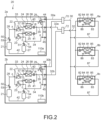
- Fig. 2 is a refrigerant circuit diagram showing a configuration example of an air conditioning device with a cooling/heating switching system 20.
- an air conditioning device in which two outdoor units 2a and 2b and three indoor units 8a, 8b, and 8c are connected in parallel will be described as an example.
- the outdoor units 2a and 2b and the indoor units 8a to 8c are common, but the number of connection pipes (a high-pressure gas pipe 30, a low-pressure gas pipe 31, and a liquid pipe 32) connecting the outdoor units 2a and 2b and the indoor units 8a to 8c differs.
- the air conditioning devices 10 and 20 with the respective systems will be described below.
- FIG. 1 A configuration and an operation example of the air conditioning device with a cooling/heating free system 10 will be described first with reference to Fig. 1 .
- the air conditioning device 10 includes the two outdoor units 2a and 2b, the three indoor units 8a, 8b, and 8c, three diversion units6a, 6b, and 6c, and branching devices 70, 71, and 72.
- the outdoor units 2a and 2b, the indoor units 8a to 8c, the diversion units 6a to 6c, and the branching devices 70 to 72 are connected to each other via the high-pressure gas pipe 30 (first gas pipe), high-pressure gas branch pipes 30a and 30b, the low-pressure gas pipe 31 (second gas pipe), low-pressure gas branch pipes 31a and 31b, the liquid pipe 32, and liquid branch pipes 32a and 32b, thereby forming the refrigerant circuit of the air conditioning device 10.
- various operations such as a heating operation (all indoor units performing a heating operation), a heating-dominated operation (where the total value of the capacity required by the indoor unit performing a heating operation exceeds the total value of the capacity required by the indoor unit performing a cooling operation), a cooling operation (all indoor units perform a cooling operation), and a cooling-dominated operation (where the total value of the capacity required by the indoor unit performing a cooling operation exceeds the total value of the capacity required by the indoor unit performing a heating operation) are possible in accordance with the open/close state of various valves provided in the outdoor units 2a and 2b and the diversion units 6a to 6c.
- the configurations of the outdoor units 2a and 2b are all the same, and corresponding parts are denoted by the same reference symbols. In the following description, only the configuration of the outdoor unit 2a will be described and description of the outdoor unit 2b will be omitted.
- the outdoor unit 2a includes a compressor 21, a first three-way valve 22 and a second three-way valve 23 that are each a first flow path switching means, a first outdoor heat exchanger 24, a second outdoor heat exchanger 25, an outdoor fan 26, an accumulator 27, a four-way valve 29 that is a second flow path switching means, a first outdoor expansion valve 40 connected to the first outdoor heat exchanger 24, and a second outdoor expansion valve 41 connected to the second outdoor heat exchanger 25.
- the compressor 21 is a variable capacity compressor whose operating capacity can be varied by being driven by a motor (not shown) whose rotation speed is controlled by an inverter.
- the discharged side of the compressor 21 is connected to a port a of the first three-way valve 22 and a port d of the second three-way valve 23 via a discharge pipe 28 and is connected to a port g of the four-way valve 29 via the discharge pipe 28 and an outdoor unit high-pressure gas pipe 33.
- the discharge pipe 28 is a refrigerant pipe that connects the discharge side of the compressor 21 and a connection point A
- the outdoor unit high-pressure gas pipe 33 is a refrigerant pipe that connects the connection point A and a stop valve 44.
- the suction side of the compressor 21 is connected to the outlet side of the accumulator 27 via a suction pipe 42, and the inlet side of the accumulator 27 is connected to a stop valve 45 via an outdoor unit low-pressure gas pipe 34.
- the first three-way valve 22 and the second three-way valve 23 are each a valve for switching the direction of the refrigerant flowing in the refrigerant circuit.
- the first three-way valve 22 includes three ports a, b, and c, and the second three-way valve 23 includes three ports d, e, and f.
- the refrigerant pipe connected to the port a is connected to the discharge pipe 28 and the outdoor unit high-pressure gas pipe 33 at the connection point A.
- the port b and one end (one refrigerant inlet/outlet) of the first outdoor heat exchanger 24 is connected via a refrigerant pipe, and the refrigerant pipe connected to the port c is connected to the outdoor unit low-pressure gas pipe 34 at a connection point D.
- the refrigerant pipe connected to the port d is connected, at the connection point A, to the refrigerant pipe connected to the discharge pipe 28 and the outdoor unit high-pressure gas pipe 33. Further, the port e and one end (one refrigerant inlet/outlet) of the second outdoor heat exchanger 25 are connected via a refrigerant pipe, and the refrigerant pipe connected to the port f is connected, at a connection point C, to the refrigerant pipe connected to the port c of the first three-way valve 22.
- the four-way valve 29 is switched such that a refrigerant flows from the outdoor unit high-pressure gas pipe 33 to each of the high-pressure gas branch pipe 30a and the high-pressure gas branch pipe 30b.
- the discharge pipe 28 is provided with a high-pressure sensor 50 that detects the pressure of the refrigerant discharged from the compressor 21 and a temperature sensor 53 that detects the temperature of the refrigerant discharged from the compressor 21. Further, between the connection point D in the outdoor unit low-pressure gas pipe 34 and the inlet side of the accumulator 27a, a low-pressure sensor 51 that detects the pressure of the refrigerant to be sucked into the compressor 21 and a suction temperature sensor 54 that detects the temperature of the refrigerant to be sucked into the compressor 21.
- One end (one refrigerant inlet/outlet) of the indoor heat exchanger 81 is connected to one port of the indoor expansion valve 82 via a refrigerant pipe, and the other end (the other refrigerant inlet/outlet) is connected to a diversion unit 6a described below via a refrigerant pipe 87.
- the indoor heat exchanger 81 functions as an evaporator in the case where the indoor unit 8a performs a cooling operation, and functions as a condenser in the case where the indoor unit 8a performs a heating operation.
- the one port of the indoor expansion valve 82 is connected to the indoor heat exchanger 81 as described above, and the other port is connected to the liquid pipe 32.
- the degree of opening of the indoor expansion valve 82 is adjusted in accordance with the required cooling capacity in the case where the indoor heat exchanger 81 functions as an evaporator, and the degree of opening is adjusted in accordance with the required heating capacity in the case where the indoor heat exchanger 81 functions as a condenser.
- the indoor fan 83 rotates by a fan motor (not shown) to take in indoor air into the indoor unit 8a, exchange heat between the refrigerant and the indoor air in the indoor heat exchanger 81, and then supply the heat-exchanged air to the inside of the room.
- various sensors are provided in the indoor unit 8a.
- the refrigerant pipe of the indoor heat exchanger 81 on the side of the indoor expansion valve 82 and the refrigerant pipe of the indoor heat exchanger 81 on the side of the diversion unit 6a are respectively provided with a refrigerant temperature sensor 84 that detects the temperature of the refrigerant and a refrigerant temperature sensor 85 that detects the temperature of the refrigerant.
- a room-temperature sensor 86 that detects the temperature of the indoor air that has flowed into the indoor unit 8a, i.e. , the indoor temperature, is provided near a suction port (not shown) of indoor air of the indoor unit 8a.
- the air conditioning device 10 includes the three diversion units 6a to 6c corresponding to the three indoor units 8a to 8c.
- the diversion units 6a to 6c respectively include first solenoid valves 61a to 61c, second solenoid valves 62a to 62c, first diversion pipes 63a to 63c, and second diversion pipes 64a to 64c. Note that since the configurations of the diversion units 6a to 6c are all the same, only the configuration of the diversion unit 6a will be described below and description of the other diversion units 6b and 6c will be omitted.
- first diversion pipe 63a is connected to the high-pressure gas pipe 30, and one end of the second diversion pipe 64a is connected to the low-pressure gas pipe 31. Further, the other end of the first diversion pipe 63a and the other end of the second diversion pipe 64a are connected to each other, and this connection part and the indoor heat exchanger 81 are connected via the refrigerant pipe 87.
- the first diversion pipe 63a and the second diversion pipe 64a are respectively provided with the first solenoid valve 61a and the second solenoid valve 62a.
- the flow path of the refrigerant in the refrigerant circuit can be switched such that the indoor heat exchanger 81 of the indoor unit 8a corresponding to the diversion unit 6a is connected to the discharge side of the compressor 21 (the side of the high-pressure gas pipe 30) or the suction side (the side of the low-pressure gas pipe 31).
- connection states of the outdoor units 2a and 2b, the indoor units 8a to 8c, and the diversion units 6a to 6c and the high-pressure gas pipe 30, the high-pressure gas branch pipes 30a and 30b, the low-pressure gas pipe 31, the low-pressure gas branch pipes 31a and 31b, the liquid pipe 32, the liquid branch pipes 32a and 32b, and the branching devices 70, 71, and 72 described above will be described with reference to Fig. 1 .
- One ends of the high-pressure gas branch pipes 30a and 30b are respectively connected to the stop valves 44 of the outdoor units 2a and 2b, and the other ends of the high-pressure gas branch pipes 30a and 30b are connected to the branching device 70.
- One end of the high-pressure gas pipe 30 is connected to this branching device 70, and the other end of the high-pressure gas pipe 30 branches to be connected to the first diversion pipes 63a to 63c of the diversion units 6a to 6c.
- One ends of the low-pressure gas branch pipes 31a and 31b are respectively connected to the stop valves 45 of the outdoor units 2a and 2b, and the other ends of the low-pressure gas branch pipes 31a and 31b are connected to the branching device 71.
- One end of the low-pressure gas pipe 31 is connected to this branching device 71, and the other end of the low-pressure gas pipe 31 branches to be connected to the second diversion pipes 64a to 64c of the diversion units 6a to 6c.
- liquid branch pipes 32a and 32b are respectively connected to the stop valves 46 of the outdoor units 2a and 2b, and the other ends of the liquid branch pipes 32a and 32b are connected to the branching device 72.
- One end of the liquid pipe 32 is connected to this branching device 72, and the other end of the liquid pipe 32 branches to be connected to the indoor expansion valves 82 of the indoor units 8a to 8c via refrigerant pipes.
- the indoor heat exchangers 81 of the indoor units 8a to 8c and the connection points between the first diversion pipes 63a to 63c and the second diversion pipes 64a to 64c in the diversion units 6a to 6c are respectively connected via the refrigerant pipes 87.
- the connections described above form the refrigerant circuit of the air conditioning device 10, and a refrigeration cycle is established by causing a refrigerant to flow through the refrigerant circuit.
- a refrigeration cycle is established by causing a refrigerant to flow through the refrigerant circuit.
- the state of the refrigerant circuit in which the indoor units 8a to 8c are capable of individually performing a cooling operation or a heating operation as shown in Fig. 1 will be referred to also as a "first refrigerant circuit state".
- the outdoor units 2a and 2b respectively include control devices 110a and 110b.
- Fig. 3 is a block diagram showing a configuration of the control devices 110a and 110b. Since the configurations of the control devices 110a and 110b are basically all the same, only the configuration of the control device 110a will be described below and description of the control device 110b will be omitted.
- the control device 110a is mounted on a control board (not shown) housed in an electrical equipment box (not shown) and includes a CPU 111a, a storage unit 112a, a refrigerant circuit selection unit 113a, and a communication unit 114a.
- the CPU 111a receives detection signals from the above-mentioned sensors of the outdoor unit 2a and receives control signals output from the indoor units 8a to 8c via the communication unit 113a.
- the CPU 111a performs various types of control such as drive control of the compressor 21, switching control of the first three-way valve 22, the second three-way valve 23, and the four-way valve 29, and control of the degree of opening of each of the first outdoor expansion valve 40 and the second outdoor expansion valve 41 on the basis of the received detection signals or control signals.
- the opening and closing control of the first solenoid valves 61a to 61c and the second solenoid valves 62a to 62c in the diversion units 6a to 6c is performed by control devices (not shown) of the indoor units 6a to 6c corresponding to the diversion units 6a to 6c, respectively.
- the storage unit 112a includes a ROM and a RAM and stores a control program of the outdoor unit 2a and a detection value corresponding to the detection signal from each sensor.
- the storage unit 112a stores a control program for executing the operation mode of the cooling/heating free system and a control program for executing the operation mode of the cooling/heating switching system described below ( Fig. 2 ).
- the refrigerant circuit selection unit 113a is for selecting either the operation mode of the cooling/heating free system or the operation mode of the cooling/heating switching system of the outdoor unit 2a.
- the CPU 111a sets the refrigerant circuit state to the first refrigerant circuit state and executes the control program for the operation mode of the cooling/heating free system.
- the CPU 111a sets the refrigerant circuit state to the second refrigerant circuit state and executes the control program for the operation mode of the cooling/heating switching system.
- the refrigerant circuit selection unit 113a is a hardware switch (switching operation unit) that is housed in the above electrical equipment box and is switched by an operator, such as a dip switch and a toggle switch.
- the refrigerant circuit selection unit 113a may be a software switch that is switched by an input signal from an electronic apparatus such as a PC. Note that the refrigerant circuit state is switched by the CPU 111a in some cases in accordance with an instruction from another outdoor unit (in this embodiment, the outdoor unit 2b) (as will be described below in detail).
- the communication unit 114a is an interface that performs communication between the outdoor unit 2a and the indoor units 8a to 8c and communication between the outdoor unit 2a and the outdoor unit 2b (communication unit 114b) and includes, for example, a short-range wireless communication module.
- control device 110b is the same as that of the control device 110a as described above, and components having the suffix "b" changed from the suffix "a" of the reference symbols given to the components (devices and members) of the control device 110a are the components of the control device 110b corresponding to the components of the control device 110a.
- the first outdoor heat exchanger 24 is caused to function as an evaporator by switching the first three-way valves 22 of the outdoor units 2a and 2b such that the port b and the port c communicate with each other (shown by a solid line in Fig. 1 ) and the second outdoor heat exchanger 25 is caused to function as an evaporator by switching the second three-way valves 23 of the outdoor units 2a and 2b such that the port e and the port f communicate with each other (shown by a solid line in Fig. 1 ).
- the four-way valves 29 of the outdoor units 2a and 2b are switched such that the port g and the port h communicate with each other and the port k and the port m communicate with each other (shown by a solid line in Fig. 1 ).
- the first solenoid valves 61a to 61c of the diversion units 6a to 6c corresponding to the indoor units 8a to 8c are opened to respectively cause refrigerants to flow through the first diversion pipes 63a to 63c and the second solenoid valves 62a to 62c are closed to shut off the second diversion pipes 64a to 64c.
- the indoor heat exchangers 81 of the indoor units 8a to 8c all function as condensers.
- the high-pressure refrigerant discharged from the compressor 21 of the outdoor unit 2a flows through the discharge pipe 28 and the outdoor unit high-pressure gas pipe 33 and flows into the high-pressure gas branch pipe 30a via the stop valve 44.
- the high-pressure refrigerant discharged from the compressor 21 of the outdoor unit 2b flows through the outdoor unit high-pressure gas pipe 33 via the discharge pipe 28 and flows into the high-pressure gas branch pipe 30b via the stop valve 44.
- the high-pressure refrigerants that have flowed into the high-pressure gas branch pipes 30a and 30b join at the branching device 70, flow through the high-pressure gas pipe 30, and branch off and flow into the diversion units 6a to 6c from the high-pressure gas pipe 30.
- the high-pressure refrigerants that have flowed into the diversion units 6a to 6c respectively flow through the first diversion pipes 63a to 63c provided with the opened first solenoid valves 61a to 61c and flow out from the diversion units 6a to 6c to flow into the indoor units 8a to 8c corresponding to the diversion units 6a to 6c.
- the high-pressure refrigerants that have flowed into the indoor units 8a to 8c flow into the respective indoor heat exchangers 81 and exchange heat with the indoor air to be condensed. This warms the indoor air, and thus, the rooms in which the indoor units 8a to 8c are installed are heated.
- the high-pressure refrigerant flowing out from the indoor heat exchanger 81 is reduced in pressure by passing through the indoor expansion valve 82.
- the degree of opening of the indoor expansion valve 82 is determined in accordance with the degree of supercooling of the refrigerant at the refrigerant outlet of the indoor heat exchanger 81.
- the degree of supercooling of the refrigerant is obtained by, for example, subtracting the refrigerant temperature at the refrigerant outlet of the indoor heat exchanger 81 detected by the refrigerant temperature sensor 84 from the high-pressure saturation temperature (corresponding to the condensation temperature in the indoor heat exchanger 81) calculated from the pressure detected by the high-pressure sensor 50 of the outdoor unit 2a/2b.
- the intermediate-pressure refrigerants flowing out from the indoor units 8a to 8c flow into the liquid pipe 32, join in the liquid pipe 32, and flow into the branching device 72.
- the intermediate-pressure refrigerant that has diverted from the branching device 72 to the liquid branch pipes 32a and 32b flows into the respective outdoor units 2a and 2b via the stop valve 46.
- the intermediate-pressure refrigerant that has flowed into the respective outdoor units 2a and 2b flows through the outdoor unit liquid pipe 35, is diverted at the connection point B, and is reduced in pressure by passing through the first outdoor expansion valve 40a and the second outdoor expansion valve 41 to be a low-pressure refrigerant.
- the degree of opening of the first outdoor expansion valve 40 is determined in accordance with the degree of superheat of the refrigerant at the refrigerant outlet of the first outdoor heat exchanger 24. Further, the degree of opening of the second outdoor expansion valve 41 is determined in accordance with the degree of superheat of the refrigerant at the refrigerant outlet of the second outdoor heat exchanger 25.
- the degree of superheat of the refrigerant is obtained by, for example, subtracting the low-pressure saturation temperature (corresponding to the evaporation temperature in the first outdoor heat exchanger 24 or the second outdoor heat exchanger 25) calculated from the pressure detected by the low-pressure sensor 51 of the outdoor unit 2a/2b from the refrigerant temperature at the refrigerant outlet of the first outdoor heat exchanger 24 or the second outdoor heat exchanger 25 detected by the first heat exchange temperature sensor 56 or the second heat exchange temperature sensor 57.
- the first outdoor heat exchanger 24 is caused to function as a condenser by switching the first three-way valves 22 of the outdoor units 2a and 2b such that the port a and the port b communicate with each other (shown by shown by a broken line in Fig. 1 ) and the second outdoor heat exchanger 25 is caused to function as a condenser by switching the second three-way valves 23 such that the port d and the port e communicate with each other (shown by shown by a broken line in Fig. 1 ).
- the four-way valves 29 of the outdoor units 2a and 2b are switched such that the port g and the port h communicate with each other and the port k and the port m communicate with each other (shown by a solid line in Fig. 1 ).
- the first solenoid valves 61a to 61c of the diversion units 6a to 6c corresponding to the indoor units 8a to 8c are closed to shut off the first diversion pipes 63a to 63c and the second solenoid valves 62a to 62c are opened to respectively cause refrigerants to flow through the second diversion pipes 64a to 64c.
- the indoor heat exchangers 81 of the indoor units 8a to 8c all function as evaporators.
- the high-pressure refrigerant discharged from the compressor 21 of the outdoor unit 2a/2b is diverted into the side of the first three-way valve 22, the side of the second three-way valve 23, and the side of the high-pressure gas pipe 30.
- the refrigerants flowing through the sides of the first three-way valve 22 and the second three-way valve 23 respectively flow into the first outdoor heat exchanger 24 and the second outdoor heat exchanger 25 and exchange heat with the outside air to be condensed.
- the refrigerant flowing through the side of the high-pressure gas pipe 30 does not flow into the indoor units 8a to 8c because the first solenoid valves 61a to 61c of the diversion units 6a to 6c are closed, and stagnates in the outdoor unit high-pressure gas pipe 33, the high-pressure gas branch pipe 30a/30b, and the high-pressure gas pipe 30.
- the cooling capacity required by the indoor units 8a to 8c exceeds a predetermined value, there is a possibility that the refrigerant in the amount necessary for achieving the required cooling capacity cannot be circulated through the refrigerant circuit when the refrigerant stagnates in the outdoor unit high-pressure gas pipe 33 and the high-pressure gas pipe 30 as described above.
- the four-way valve 29 is switched such that the port g and the port k communicate with each other and the port h and the port m communicate with each other (shown by shown by a broken line in Fig. 1 ).
- the refrigerant condensed in the first outdoor heat exchanger 24 and the second outdoor heat exchanger 25 of the outdoor unit 2a respectively pass through the first outdoor expansion valve 40 and the second outdoor expansion valve 41, which are fully opened by the control device 110a, and flow into the liquid branch pipe 32a via the stop valve 46.
- the refrigerants condensed in the first outdoor heat exchanger 24 and the second outdoor heat exchanger 25 of the outdoor unit 2b respectively pass through the first outdoor expansion valve 40 and the second outdoor expansion valve 41, which are fully opened by the control device 110b, and flow into the liquid branch pipe 32b via the stop valve 46.
- the intermediate-pressure refrigerants that have flowed into the liquid branch pipes 32a and 32b join at the branching device 72, flow through the liquid pipe 32, and branch off and flow into the indoor units 8a to 8c from the liquid pipe 32.
- the state of the refrigerant circuit is determined in accordance with the result of a comparison between the total value of the cooling capacity required by the indoor unit performing a cooling operation and the total value of the heating capacity required by the indoor unit performing a heating operation.
- a heating-dominated operation in which the first outdoor heat exchanger 24 and the second outdoor heat exchanger 25 are caused to function as evaporators is performed in the case where the indoor units 8a and 8b perform a heating operation, the indoor unit 8c performs a cooling operation, and the heating capacity required by the two indoor units 8a and 8b performing a heating operation is larger than the cooling capacity required by the one indoor unit 8c performing a cooling operation, and a cooling-dominated operation in which the first outdoor heat exchanger 24 and the second outdoor heat exchanger 25 are caused to function as condensers is performed in the case where the indoor units 8a and 8b perform a cooling operation, the indoor unit 8c performs a heating operation, and the cooling capacity required by the two indoor units 8a and 8b performing a cooling operation is larger than the heating capacity required by the one indoor unit 8c performing a heating operation.
- the first three-way valve 22 is switched such that the port b and the port c communicate with each other (shown by a solid line in Fig. 1 ), and the second three-way valve 23 is switched such that the port e and the port f communicate with each other (shown by a solid line in Fig. 1 ).
- the four-way valve 29 is switched such that the port g and the port h communicate with each other and the port k and the port m communicate with each other (shown by a solid line in Fig. 1 ).
- both the first outdoor heat exchanger 24 and the second outdoor heat exchanger 25 function as evaporators.
- first solenoid valves 61a and 61b of the two diversion units 6a and 6b corresponding to the two indoor units 8a and 8b performing a heating operation are opened to connect the first diversion pipes 63a and 63b, and the second solenoid valves 62a and 62b are closed to shut off the second diversion pipes 64a and 64b.
- the indoor heat exchangers 81 of the two indoor units 8a and 8b function as condensers.
- the first solenoid valve 61c of the diversion unit 6c corresponding to the indoor unit 8c performing a cooling operation is closed to shut off the first diversion pipe 63c, and the second solenoid valve 62c is opened to connect the second diversion pipe 64c.
- the indoor heat exchanger 81 of the indoor unit 8c function as an evaporator.
- the high-pressure refrigerants discharged from the compressors 21 of the outdoor units 2a and 2b flow through the high-pressure gas pipe 30 and branch oof and flow into the diversion units 6a and 6b.
- the high-pressure refrigerants that have flowed into the diversion units 6a and 6b respectively flow through the first diversion pipes 63a and 63b equipped with the opened first solenoid valves 61a and 61b, flow out from the diversion units 6a and 6b, and flow into the corresponding indoor units 8a and 8b.
- the high-pressure refrigerant that has flowed into the indoor unit 8a/8b flows into the indoor heat exchanger 81 and exchanges heat with the indoor air to be condensed, and thus, the rooms in which the indoor units 8a and 8b are installed are heated.
- the high-pressure refrigerant condensed in the indoor heat exchanger 81 is reduced in pressure by passing through the indoor expansion valve 82 to be an intermediate-pressure refrigerant.
- control unit of the indoor unit 8a/8b obtains the degree of supercooling of the refrigerant at the indoor heat exchanger 81 that is a condenser from the refrigerant temperature detected by the refrigerant temperature sensor 84 and the high-pressure saturation temperature obtained from the outdoor unit 2a/2b, and the degree of opening of the indoor expansion valve 82 is determined in accordance therewith.
- the intermediate-pressure refrigerants flowing out from the indoor units 8a and 8b flow into the liquid pipe 32. Then, part of the intermediate-pressure refrigerant that has joined in the liquid pipe 32 flows into the outdoor units 2a and 2b through the branching tube 72 and the liquid branch pipes 32a and 32b, and the remainer flows through the liquid pipe 32 and flows into the indoor unit 8c.
- the intermediate-pressure refrigerant that has flowed into the outdoor unit 2a/2b is reduced in pressure to be a low-pressure refrigerant when passing through the first outdoor expansion valve 40 and the second outdoor expansion valve 41 whose degrees of opening correspond to the degrees of superheat of the first outdoor heat exchanger 24 and the second outdoor heat exchanger 25, and flows into the first outdoor heat exchanger 24 and the second outdoor heat exchanger 25.
- the low-pressure refrigerants that have flowed into the first outdoor heat exchanger 24 and the second outdoor heat exchanger 25 exchange heat with the outside air to be evaporated.
- the low-pressure refrigerants flowing out from the first outdoor heat exchanger 24 and the second outdoor heat exchanger 25 respectively pass through the first three-way valve 22 and the second three-way valve 23, then pass through the accumulator 27, and are sucked into the compressor 21 to be compressed again.
- the intermediate-pressure refrigerant that has flowed into the indoor unit 8c is reduced in pressure at the indoor expansion valve 82 to be a low-pressure refrigerant and flows into the indoor heat exchanger 81.
- the low-pressure refrigerant that has flowed into the indoor heat exchanger 81 exchanges heat with the indoor air to be evaporated, and thus, the room in which the indoor unit 8c is installed is cooled.
- the degree of superheat of the refrigerant at the indoor heat exchanger 81 that is an evaporator is obtained from the refrigerant temperatures detected by the refrigerant temperature sensors 84 and 85, and the degree of opening of the indoor expansion valve 82 of the indoor unit 8c is determined in accordance therewith.
- the low-pressure refrigerant flowing out from the indoor heat exchanger 8c flows into the diversion unit 6c, flows through the second diversion pipe 64c equipped with the opened second solenoid valve 62c, and flows into the low-pressure gas pipe 31.
- the low-pressure refrigerant that has flowed into the low-pressure gas pipe 31 flows into the outdoor units 2a and 2b through the branching tube 71 and the low-pressure gas branch pipes 31a and 31b, passes through the accumulator 27, and is sucked into the compressor 21 to be compressed again.
- the first three-way valve 22 is switched such that the port a and the port b communicate with each other (shown by shown by a broken line in Fig. 1 ) and the second three-way valve 23 is switched such that the port d and the port e communicate with each other (shown by shown by a broken line in Fig. 1 ).
- the four-way valve 29 is switched such that the port g and the port h communicate with each other and the port k and the port m communicate with each other(shown by a solid line in Fig. 1 ).
- both the first outdoor heat exchanger 24 and the second outdoor heat exchanger 25 function as condensers.
- the solenoid valves 61a and 61b of the two diversion units 6a and 6b corresponding to the two indoor units 8a and 8b performing a cooling operation are closed to shut off the first diversion pipes 63a and 63b, and the second solenoid valves 62a and 62b are closed to connect the second diversion pipes 64a and 64b.
- the indoor heat exchangers 81 of the two indoor units 8a and 8b function as evaporators.
- the solenoid valve 61c of the diversion unit 6c corresponding to the indoor unit 8c performing a heating operation is closed to connect the first diversion pipe 63c, and the second solenoid valve 62c is closed to shut off the second diversion pipe 64c.
- the indoor heat exchanger 81 of the indoor unit 8c functions as a condenser.
- the refrigerants condensed in the first outdoor heat exchanger 24 and the second outdoor heat exchanger 25 respectively pass through the first outdoor expansion valve 40 and the second outdoor expansion valve 41 whose degrees of opening are set by the control devices 110a and 110b to correspond to the difference between the discharge pressure of the compressor 21 that has taken in the refrigerant and the liquid pressure to be an intermediate-pressure refrigerant, flow through the liquid pipe 32, and branch off and flow into the indoor units 8a and 8b.
- the intermediate-pressure refrigerant that has flowed into the indoor unit 8a/8b is reduced in pressure at the indoor expansion valve 82 to be a low-pressure refrigerant, and flows into the indoor heat exchanger 81.
- the low-pressure refrigerant that has flowed into the indoor heat exchanger 81 exchanges heat with the indoor air to be evaporated, and thus, the rooms in which the indoor units 8a and 8b are installed are cooled.
- the degree of superheat of the refrigerant at the indoor heat exchanger 81 that is an evaporator is obtained from the refrigerant temperatures detected by the refrigerant temperature sensors 84 and 85, and the degree of opening of the indoor expansion valve 82 is determined in accordance therewith.
- the low-pressure refrigerants flowing out from the indoor heat exchangers 81 of the indoor units 8a and 8b flow into the diversion units 6a and 6b, flow through the second diversion pipes 64a and 64b equipped with the opened second solenoid valves 62a and 62b, and flow into the low-pressure gas pipe 31.
- the high-pressure refrigerant that has flowed through the high-pressure gas pipe 30 and flowed into the diversion unit 6c flows through the first diversion pipe 63c equipped with the opened solenoid valve 61c and flows into the indoor unit 8c.
- the high-pressure refrigerant that has flowed into the indoor unit 8c flows into the indoor heat exchanger 81 and exchanges heat with the indoor air to be condensed, and thus, the room in which the indoor unit 8c is installed is heated.
- the high-pressure refrigerant flowing out from the indoor heat exchanger 81 is reduced in pressure by passing through the indoor expansion valve 82 to be an intermediate-pressure refrigerant.
- the degree of supercooling of the refrigerant at the indoor heat exchanger 81 that is a condenser is obtained from the refrigerant temperature detected by the refrigerant temperature sensor 84 and the high-pressure saturation temperature obtained from the outdoor unit 2a/2b, and the degree of opening of the indoor expansion valve 82 of the indoor unit 8c is determined in accordance therewith.
- the intermediate-pressure refrigerant that has flowed out from the indoor unit 8c and flowed into the liquid pipe 32 passes through the branching tube 72 and the liquid branching tubes 32a and 32b and flows into the outdoor units 2a and 2b.
- the intermediate-pressure refrigerant that has flowed into the outdoor unit 2a/2b is reduced in pressure to be a low-pressure refrigerant when passing through the first outdoor expansion valve 40 and the second outdoor expansion valve 41 whose degrees of opening correspond to the degrees of superheat of the first outdoor heat exchanger 24 and the second outdoor heat exchanger 25, and flows into the first outdoor heat exchanger 24 and the second outdoor heat exchanger 25.
- the air conditioning device with a cooling/heating switching system 20 does not include the diversion units 6a to 6c, the low-pressure gas pipe 31, the low-pressure gas branch pipes 31a and 31b, and the branching tube 71 unlike the above-mentioned air conditioning device with a cooling/heating free system. That is, in the air conditioning device with a cooling/heating switching system 20, the stop valves 45 of the outdoor units 2a and 2b are closed, and the outdoor units 2a and 2b and the indoor units 8a to 8c are connected in parallel via two connection pipes, i.e., a gas pipe 30 (corresponding to the high-pressure gas pipe 30 in the air conditioning device with a cooling/heating free system 10) and the liquid pipe 32. Since the outdoor units 2a and 2b and the indoor units 8a to 8c in the air conditioning device with a cooling/heating switching system 20 have the same configurations as those in the air conditioning device with a cooling/heating free system 10, description thereof is omitted.
- the first three-way valve 22 of each of the outdoor units 2a and 2b is switched such that the port b and the port c communicate with each other (shown by a solid line in Fig. 2 ) and the second three-way valve 23 is switched such that the port e and the port f communicate with each other (shown by a solid line in Fig. 2 ), as in the air conditioning device with a cooling/heating free system 10 during the full heating operation.
- the four-way valve 29 of each of the outdoor units 2a and 2b is switched such that the port g and the port h communicate with each other and the port k and the port m communicate with each other (shown by a solid line in Fig. 2 ).
- the first outdoor heat exchanger 24 and the second outdoor heat exchanger 25 of each of the outdoor units 2a and 2b to function as evaporators and cause the indoor unit 81 of each of the indoor units 8a to 8c to function as a condenser.
- the first three-way valve 22 of each of the outdoor units 2a and 2b is switched such that the port a and the port b communicates with each other (shown by a broken line in Fig. 2 ) and the second three-way valve 23 is switched such that the port d and the port e communicate with each other (shown by a broken line in Fig. 2 ), as in the air conditioning device with a cooling/heating free system 10 during the full cooling operation.
- the four-way valve 29 of each of the outdoor units 2a and 2b is switched such that the port g and the port k communicate with each other and the port h and the port m communicate with each other (shown by a broken line in Fig. 2 ).
- the first outdoor heat exchanger 24 and the second outdoor heat exchanger 25 of each of the outdoor units 2a and 2b to function as condensers and the indoor unit 81 of each of the indoor units 8a to 8c to function as an evaporator.
- the refrigerant circuit of the air conditioning device 20 is configured as described above, and a refrigeration cycle is established by causing a refrigerant to flow through the refrigerant circuit.
- a refrigeration cycle is established by causing a refrigerant to flow through the refrigerant circuit.
- the state of the refrigerant circuit in which the indoor units 8a to 8c are capable of simultaneously performing a cooling operation or a heating operation as shown in Fig. 2 will be referred to also as a "second refrigerant circuit state".
- an air conditioning device that includes the four-way valve 29 and is capable of supporting both the cooling/heating switching system and the cooling/heating free system by switching this four-way valve 29, all outdoor units need to be unified into either the cooling/heating switching system or the cooling/heating free system during operation.
- a switching means corresponding to the refrigerant circuit selection units 113a and 113b in Fig. 3
- the switching means is operated by an operator for each outdoor unit during installation.
- an air conditioning device can be operated in some cases while all outdoor units are not unified into either the cooling/heating switching system or the cooling/heating free system.
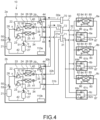
- the outdoor unit 2a is mistakenly switched to the cooling/heating switching system in an air conditioning device that operates in the cooling/heating free system.
- the four-way valve 29 of the outdoor unit 2a is switched to a state in which the port g and the port k communicate with each other and the port h and the port m communicate with each other (hereinafter, referred to also as an OFF state) and the four-way valve 29 of the outdoor unit 2b is switched to a state in which the port g and the port h communicate with each other and the port k and the port m communicate with each other (hereinafter, referred to also as an ON state).
- the refrigerant discharged from the compressor 21 of the outdoor unit 2b in which the cooling/heating free system is selected flows into the high-pressure gas branch pipe 30b via the four-way valve 29 of the outdoor unit 2b, joins with the refrigerants flowing out from the indoor heat exchangers 81 of the indoor units 8a to 8c that function as evaporators at the branching device 70, and then flows into the outdoor unit 2a in which the cooling/heating switching system is selected through the high-pressure gas branch pipe 30a.
- the high-temperature and high-pressure refrigerant that has flowed from the outdoor unit 2b flows into the outdoor unit low-pressure gas pipe 34 in the outdoor unit 2a and is sucked into the compressor 21 of the outdoor unit 2a.
- the outdoor unit 2a with the cooling/heating switching system there is a possibility that the low pressure rises and the high pressure also rises accordingly, which causes the temperature of the refrigerant discharged from the compressor 21 to exceed the upper limit value of the usable range in the performance.
- the refrigerant circuit is in the state shown in Fig. 5 .
- the four-way valve 29 of the outdoor unit 2a is set to the OFF state
- the four-way valve 29 of the outdoor unit 2b is set to the ON state
- the high-temperature and high-pressure refrigerant that has flowed from the outdoor unit 2b flows into the outdoor unit low-pressure gas pipe 34 in the outdoor unit 2a and is sucked into the compressor 21 of the outdoor unit 2a .
- one of a plurality of outdoor units transmits, when the one outdoor unit has selected either a cooling/heating free system (first refrigerant circuit state) or a cooling/heating switching system (second refrigerant circuit state), a state signal including information relating to the selected refrigerant circuit state to a different outdoor unit.
- the different outdoor unit that has received the state signal selects the same refrigerant circuit state as the refrigerant circuit state selected by the one outdoor unit, regardless of the refrigerant circuit state selected by the refrigerant circuit selection unit.
- one outdoor unit 2a is set as a parent outdoor unit and the other outdoor unit is set as a child outdoor unit that operates in accordance with an instruction from the parent outdoor unit.
- the outdoor unit 2a will be referred to also as a parent outdoor unit 2a and the outdoor unit 2b will be referred to also as a child outdoor unit 2b.
- Fig. 6 is a flowchart showing an example of a control procedure of each of the outdoor units 2a and 2b relating to the setting of the refrigerant circuit state in the present invention from when power is supplied to the air conditioning device 10 after installing the air conditioning device 10 until the operation is started.
- the control device 110a of the parent outdoor unit 2a determines the refrigerant circuit state of the parent outdoor unit 2a (Steps 101 and 102).
- the refrigerant circuit state of the parent outdoor unit 2a is determined by the CPU 111a on the basis of whether the first refrigerant circuit state or the second refrigerant circuit state is selected in the refrigerant circuit selection unit 113a of the control device 110a.
- the CPU 111a stores the determination result of the refrigerant circuit state in the storage unit 112a.
- both the outdoor units 2a and 2b need to be in the first refrigerant circuit state.
- both the outdoor units 2a and 2b need to be in the second refrigerant circuit state.
- the CPU 111a of the control device 110a generates a state signal including information relating to the refrigerant circuit state selected by the parent outdoor unit 2a and transmits the generated state signal from the communication unit 114a to the communication unit 114b of the child outdoor unit 2b (Step 103). Specifically, a state signal relating to the first refrigerant circuit state is transmitted when the parent outdoor unit 2a has selected the first refrigerant circuit state, and a state signal relating to the second refrigerant circuit state is transmitted when the parent outdoor unit 2a has selected the second refrigerant circuit state.
- the control device 110b of the child outdoor unit 2b receives the state signal by the communication unit 114b and sets the child outdoor unit 2b to the same refrigerant circuit state as the refrigerant circuit state selected by the parent outdoor unit 2a on the basis of the received state signal (Step 104).
- the CPU 111b of the child outdoor unit 2b sets the child outdoor unit 2b to the first refrigerant circuit state when the child outdoor unit 2b has received a state signal relating to the first refrigerant circuit state and sets the child outdoor unit 2b to the second refrigerant circuit state when the child outdoor unit 2b has received a state signal relating to the second refrigerant circuit state.
- the CPU 111b may store the received state signal in the storage unit 112b.
- the CPU 111b selects the refrigerant circuit state included in the state signal transmitted from the parent outdoor unit 2a as described above, and thus, the refrigerant circuit state of the child outdoor unit 2b is switched to the same refrigerant circuit state as that of the parent outdoor unit 2a even if the refrigerant circuit state of the child outdoor unit 2b is mistakenly made different from the refrigerant circuit state of the parent outdoor unit 2a by operating the refrigerant circuit selection unit 113b.
- the parent outdoor unit 2a and the child outdoor unit 2b can be set to the same refrigerant circuit state.
- Fig. 7 is a flowchart showing an example of a control procedure of each of the outdoor units 2a and 2b relating to the setting of the refrigerant circuit state in the present invention from when the power supply to the parent outdoor unit 2a and the child outdoor unit 2b is cut off and then the power supply to them is resumed until the operation is started.
- the control device 110a of the parent outdoor unit 2a checks the refrigerant circuit state of the parent outdoor unit 2a (Steps 201 and 202).
- the refrigerant circuit state of the parent outdoor unit 2a is determined by the CPU 111a on the basis of whether the refrigerant circuit selection unit 113a of the control device 110a has selected the first refrigerant circuit state or the second refrigerant circuit state, as described above.
- the CPU 111a stores the determination result of the refrigerant circuit state in the storage unit 112a.
- the CPU 111a of the control device 110a generates a state signal including information relating to the checked refrigerant circuit state of the parent outdoor unit 2a and transmits the generated state signal from the communication unit 114a to the communication unit 114b of the child outdoor unit 2b (Step 203).
- control device 110b of the child outdoor unit 2b sets the child outdoor unit 2b to the same refrigerant circuit state as the refrigerant circuit state selected by the parent outdoor unit 2a on the basis of the state signal received by the communication unit 114b (Step 204).
- the operation of the parent outdoor unit 2a and the child outdoor unit 2b is resumed (Step 205).
- the refrigerant circuit state of the child outdoor unit 2b can be set on the basis of the state signal generated in accordance with the refrigerant circuit state set by the refrigerant circuit selection unit 113a of the parent outdoor unit 2a when power is restored, and the operation can be resumed.
- the refrigerant circuit state of the child outdoor unit 2b can be automatically set to the refrigerant circuit state of the parent outdoor unit 2a before the reset when the power supply is resumed.
- the refrigerant circuit state of the child outdoor unit 2b may be set again in the same procedure as described above.
- Fig. 8 is a flowchart showing an example of a control procedure of each of the outdoor units 2a and 2b relating to the setting of the refrigerant circuit state in the present invention from when the power supply to only the child outdoor unit 2b is cut off and then the power supply to the child outdoor unit 2b is resumed until the operation is started.
- the parent outdoor unit 2a is capable of knowing whether or not the power supply to the child outdoor unit 2b is cut off on the basis of whether or not the above periodic communication is being performed.
- the control device 110a of the parent outdoor unit 2a When detecting that the power supply to the child outdoor unit 2b has been resumed due to the resumption of communication with the child outdoor unit 2b that had been interrupted, the control device 110a of the parent outdoor unit 2a generates a state signal including the refrigerant circuit state of the parent outdoor unit 2a and transmits the generated state signal to the child outdoor unit 2b (Steps 301 and 302).
- control device 110a may determine the refrigerant circuit state of the parent outdoor unit 2a again on the basis of the refrigerant circuit selection unit 113a or may read, in the case where the refrigerant circuit state determined at the start of the operation of the parent outdoor unit 2a is stored in the storage unit 112a, this refrigerant circuit state from the storage unit 112a.
- the control device 110b of the child outdoor unit 2b sets the child outdoor unit 2b to the same refrigerant circuit state as that of the refrigerant circuit state selected by the parent outdoor unit 2a on the basis of the state signal received by the communication unit 114b (Step 303). After the setting of the refrigerant circuit state of the child outdoor unit 2b is completed, the operation of the child outdoor unit 2b is resumed (Step 304).
- the refrigerant circuit state of the child outdoor unit 2b when the power supply to the child outdoor unit 2b is cut off and then the power is restored, the refrigerant circuit state of the child outdoor unit 2b can be set on the basis of the state signal including the refrigerant circuit state of the parent outdoor unit 2a and the operation can be resumed.
- the refrigerant circuit state of the child outdoor unit 2b can be automatically set to the refrigerant circuit state of the parent outdoor unit 2a before the reset when the power supply to the child outdoor unit 2a is resumed.
- the refrigerant circuit state of the child outdoor unit 2a can be automatically restored to the refrigerant circuit state before the power outage when power is restored, so that the operation of the parent outdoor unit 2a and the child outdoor unit 2b can be resumed without the need for an operator to perform an operation of setting the refrigerant circuit state again.
- the air conditioning devices 10 and 20 each including the two outdoor units 2a and 2b and the three indoor units 8a to 8c have been described as an example in the above embodiment, the numbers of outdoor units and indoor units are not limited to this example, the number of outdoor units may be three or more, and the number of indoor units may be two or four or more. Note that in the case where the number of outdoor units is three or more, one of the outdoor units only needs to be set as a parent outdoor unit and the refrigerant circuit states of the remaining outdoor units only need to match the refrigerant circuit state of the parent outdoor unit.
- connection pipes the high-pressure gas pipe 30, the low-pressure gas pipe 31, and the liquid pipe 32
- the present technology is not limited thereto and two connection pipes may be used to configure an air conditioning device with a cooling/heating free system.
- first three-way valve 22 and the second three-way valve 23 have been adopted as a first flow path switching means in the above embodiment
- the present technology is not limited thereto and another switching valve such as a four-way valve may be adopted.
- the four-way valve 29 has been adopted as a second flow path switching means
- the present technology is not limited thereto and two solenoid on-off valves may be adopted, for example, as shown in Fig. 9 .
- Fig. 9 is a refrigerant circuit diagram of the outdoor unit 2a/2b in which two solenoid on-off valves (a first solenoid on-off valve 29a and a second solenoid on-off valve 29b) have been adopted as second flow path switching means.
- the first solenoid on-off valve 29 and the second solenoid on-off valve are each a switching valve that only opens and closes.
- the first solenoid on-off valve 29a is placed on the outdoor unit high-pressure gas pipe 33 and switches the connection/disconnection between the discharge side of the compressor 21 and the stop valve 44 in accordance with a command from the control device 110a/110b.
- the second solenoid on-off valve 29b is placed on a refrigerant pipe 37 that connects the outdoor unit high-pressure gas pipe 33 and the outdoor unit low-pressure gas pipe 34 to each other and switches the connection/disconnection between the outdoor unit high-pressure gas pipe 33 and the outdoor unit low-pressure gas pipe 34 in accordance with a command from the control device 110a/110b.
- the first solenoid on-off valve 29a is set to the ON state during all of the full heating operation, the full cooling operation, the heating-dominated operation, and the cooling-dominated operation, and the second solenoid on-off valve 29b is set to the OFF state during all of the above operations.
- the first solenoid on-off valve is set to OFF and the second solenoid on-off valve is set to ON during the cooling operation, and the first solenoid on-off valve is set to ON and the second solenoid on-off valve 29b is set to OFF during the heating operation.
Landscapes
- Engineering & Computer Science (AREA)
- Mechanical Engineering (AREA)
- General Engineering & Computer Science (AREA)
- Chemical & Material Sciences (AREA)
- Combustion & Propulsion (AREA)
- Physics & Mathematics (AREA)
- Thermal Sciences (AREA)
- Human Computer Interaction (AREA)
- Air Conditioning Control Device (AREA)
- Compression-Type Refrigeration Machines With Reversible Cycles (AREA)
Abstract
[Object] To provide an air conditioning device that is capable of reliably unifying all outdoor units into a cooling/heating switching system or a cooling/heating free system.
[Solving Means] An air conditioning device according to an embodiment of the present invention includes: a plurality of outdoor units; and a plurality of indoor units, the air conditioning device being capable of selecting either a first refrigerant circuit state or a second refrigerant circuit state, each of the indoor units being capable of individually performing a cooling operation and a heating operation in the first refrigerant circuit state, each of the indoor units being capable of simultaneously performing a cooling operation or a heating operation, a communication unit of one of the plurality of outdoor units transmitting, when the one outdoor unit has selected either the first refrigerant circuit state or the second refrigerant circuit state, a state signal including information relating to the selected refrigerant circuit state to a communication unit of a different outdoor unit, the different outdoor unit that has received the state signal selecting the same refrigerant circuit state as the refrigerant circuit state selected by the one outdoor unit.
Description
- The present invention relates to an air conditioning device that includes a plurality of outdoor units connected to each of a plurality of indoor units via refrigerant pipes.
- An air conditioning device that includes a plurality of indoor units and is capable of switching between an operation system in which all indoor units perform either colling or heating (hereinafter, referred to also as a cooling/heating switching system) and an operation system in which each indoor unit is capable of selectively performing either cooling or heating (hereinafter, referred to also as a cooling/heating free system) has been known. For example,
Patent Literature 1 discloses an air conditioning device that is capable of supporting both the cooling/heating switching system and the cooling/heating free system with one outdoor unit. - The air conditioning device with a cooling/heating free system is capable of selectively executing a full heating operation, a full cooling operation, a heating-dominated operation, and a cooling-dominated operation. The full heating operation is an operation mode in which all indoor units perform a heating operation, and the full cooling operation is an operation mode in which all indoor units perform a cooling operation. The heating-dominated operation is an operation mode in which an indoor unit that performs a cooling operation and an indoor unit that performs a heating operation are mixed, the operation mode being performed when the total value of the capacity required by the indoor unit performing a heating operation exceeds the total value of the capacity required by the indoor unit performing a cooling operation. Then, the cooling-dominated operation is an operation mode in which an indoor unit that performs a cooling operation and an indoor unit that performs a heating operation are mixed, the operation mode being performed when the total value of the capacity required by the indoor unit performing a cooling operation exceeds the total value of the capacity required by the indoor unit performing a heating operation.
- The configuration of the refrigerant circuit differs between the outdoor unit with the cooling/heating switching system and the outdoor unit with the cooling/heating free system. The number of connection pipes connecting the indoor units and the outdoor units is two (a gas pipe and a liquid pipe) in the cooling/heating switching system, whereas the number of connection pipes connecting the indoor units and the outdoor unit is three, i.e., two gas pipes (a high-pressure gas pipe and a low-pressure gas pipe) and one liquid pipe, in the cooling/heating free system.
- In the cooling/heating free system, a refrigerant flows through each refrigerant pipe as follows in accordance with an operation mode. First, the high-pressure gas pipe is a connection pipe through which a high-pressure gas refrigerant discharged from a compressor flows during the full heating operation, the heating-dominated operation, and the cooling-dominated operation. Further, the low-pressure gas pipe is a connection pipe through which a low-pressure gas refrigerant flowing out from an indoor heat exchanger that functions as an evaporator during the full cooling operation and the cooling-dominated operation. Then, the liquid pipe is a refrigerant pipe through which an intermediate-pressure liquid refrigerant flowing out from an outdoor heat exchanger that functions as a condenser during the full cooling operation and the cooling-dominated operation flows, and is a connection pipe through which an intermediate-pressure liquid refrigerant flowing into an outdoor heat exchanger that functions as an evaporator during the full heating operation and the heating-dominated operation flows.
- The number of these connection pipes to be used (connected) is determined by the selected operation system (cooling/heating switching system/cooling/heating free system), and the refrigerant circuit of the outdoor unit is switched between a refrigerant circuit for a cooling/heating switching system and a refrigerant circuit for a cooling/heating free system by a flow path switching valve built into the outdoor unit.
- Patent Literature 1:
Japanese Patent Application Laid-open No. 2008-111589 - In recent years, an air conditioning device that is capable of supporting both a cooling/heating switching system and a cooling/heating free system has been developed. In this type of air conditioning device, all outdoor units need to be unified into either the cooling/heating switching system or the cooling/heating free system during operation. In general, assumption is made that each of the outdoor units that are capable of supporting both the cooling/heating switching system and the cooling/heating free system is provided with a switching means such as a dip switch for switching the refrigerant circuit to that for either a cooling/heating switching system or a cooling/heating free system and the switching means is operated by an operator for each outdoor unit during installation. However, due to an operation error or forgetting to operate the above switching means, an air conditioning device can be operated in some cases while all outdoor units are not unified into either the cooling/heating switching system or the cooling/heating free system.
- For example, if an air conditioning device that operates in the cooling/heating free system is mixed with an outdoor unit with the cooling/heating switching system, there is a possibility that a refrigerant flowing out from an outdoor unit with the cooling/heating free system flows into a gas pipe of the outdoor unit with the cooling/heating switching system, which causes the low pressure to rise and exceed the usable range in the performance of the compressor and that the high pressure rises as the low pressure rises, which causes the temperature of the refrigerant discharged from the compressor to exceed the usable range. Further, an air conditioning device that operates in the cooling/heating switching system is mixed with an outdoor unit with the cooling/heating free system, there is a possibility that due to nonconnection of a low-pressure gas pipe of the outdoor unit with the cooling/heating free system to a refrigerant pipe, the refrigerant and refrigerating oil do not return to the outdoor unit, which results in an excessive drop in low pressure and a shortage of refrigerating oil.
- In view of the circumstances as described above, it is an object of the present invention to provide an air conditioning device that includes a plurality of outdoor units and is capable of reliably unifying all outdoor units into a cooling/heating switching system or a cooling/heating free system, the outdoor units being capable of selecting the cooling/heating switching system and the cooling/heating free system.
- An air conditioning device according to an embodiment of the present invention is an air conditioning device, including: a plurality of outdoor units; a plurality of indoor units; and a plurality of connection pipes that connects each of the indoor units to the plurality of outdoor units in parallel, the air conditioning device being capable of selecting either a first refrigerant circuit state or a second refrigerant circuit state, each of the indoor units being capable of individually performing a cooling operation and a heating operation in the first refrigerant circuit state, each of the indoor units being capable of simultaneously performing a cooling operation or a heating operation,
- each of the plurality of outdoor units including a communication unit that communicates with each other and a refrigerant circuit selection unit that selects either the first refrigerant circuit state or the second refrigerant circuit state,
- the communication unit of one of the plurality of outdoor units transmitting, when the one outdoor unit has selected either the first refrigerant circuit state or the second refrigerant circuit state, a state signal including information relating to the selected refrigerant circuit state to the communication unit of a different outdoor unit,
- the different outdoor unit that has received the state signal selecting the same refrigerant circuit state as the refrigerant circuit state selected by the one outdoor unit.
- The refrigerant circuit selection unit may be a switching operation unit that selects either the first refrigerant circuit state or the second refrigerant circuit state, and the state signal may include information relating to the refrigerant circuit state selected by the switching operation unit.
- The one outdoor unit of the plurality of outdoor units may be set as a parent outdoor unit, the different outdoor unit may be set as a child outdoor unit that operates in accordance with an instruction from the parent outdoor unit, and the child outdoor unit may select the same refrigerant circuit state as the refrigerant circuit state selected by the parent outdoor unit on the basis of the state signal transmitted from the parent outdoor unit.
- The one outdoor unit of the plurality of outdoor units may be set as a parent outdoor unit, the different outdoor unit may be set as a child outdoor unit that operates in accordance with an instruction from the parent outdoor unit, and the child outdoor unit may select, when the refrigerant circuit state selected by the switching operation unit of the child outdoor unit the refrigerant circuit state included in the state signal transmitted from the parent outdoor unit differ, the refrigerant circuit state included in the state signal transmitted from the parent outdoor unit.
- The parent outdoor unit may check, when supply of electric power to the plurality of outdoor units is started or resumed, the refrigerant circuit state selected by the switching operation unit of the parent outdoor unit and transmit the state signal including the checked refrigerant circuit state to the child outdoor unit.
- The parent outdoor unit may transmit, when supply of electric power to the child outdoor unit is started or resumed, the state signal including the refrigerant circuit state selected by the parent outdoor unit to the child outdoor unit.
- Each of the plurality of outdoor units may include a compressor, an outdoor heat exchanger, a first flow path switching means, and a second flow path switching means, and one refrigerant inlet/outlet of the outdoor heat exchanger may be selectively connected to a refrigerant suction pipe or a refrigerant discharge pipe of the compressor via the first flow path switching means. Three connection pipes including a first gas pipe and a second gas pipe that are selectively connected to the refrigerant suction pipe or the refrigerant discharge pipe via the second flow path switching means and a liquid pipe that is connected to the other refrigerant inlet/outlet of the outdoor heat exchanger may be used as the plurality of connection pipes in the first refrigerant circuit state, and two connection pipes including the first gas pipe and the liquid pipe may be used as the plurality of connection pipes in the second refrigerant circuit state.
- According to the present invention, in an air conditioning device that includes a plurality of outdoor units capable of selecting a cooling/heating switching system and a cooling/heating free system, it is possible to reliably unify all outdoor units into a cooling/heating switching system or a cooling/heating free system.
-
- [
Fig. 1] Fig. 1 is a refrigerant circuit diagram showing an air conditioning device with a cooling/heating free system. - [
Fig. 2] Fig. 2 is a refrigerant circuit diagram showing an air conditioning device with a cooling/heating switching system. - [
Fig. 3] Fig. 3 is a block diagram showing a configuration of a control device. - [
Fig. 4] Fig. 4 is a refrigerant circuit diagram showing a state in which an air conditioning device with the cooling/heating free system is mixed with an outdoor unit with the cooling/heating switching system. - [
Fig. 5] Fig. 5 is a refrigerant circuit diagram showing a state in which an air conditioning device with the cooling/heating switching system is mixed with an outdoor unit with the cooling/heating free system. - [
Fig. 6] Fig. 6 is a flowchart showing an example of a control procedure of each outdoor unit. - [
Fig. 7] Fig. 7 is a flowchart showing an example of a control procedure of each outdoor unit when a power source is restored. - [
Fig. 8] Fig. 8 is a flowchart showing another example of the control procedure of each outdoor unit when a power source is restored. - [
Fig. 9] Fig. 9 is a refrigerant circuit diagram showing a modified example of the outdoor unit. Mode(s) for Carrying Out the Invention - An embodiment of the present invention will be described below with reference to the drawings.
- An air conditioning device according to this embodiment includes a plurality of outdoor units and a plurality of indoor units and is capable of selecting an operation system in which all indoor units perform either colling or heating (cooling/heating switching system) and an operation system in which each indoor unit is capable of selectively performing either cooling or heating (cooling/heating free system).
-
Fig. 1 is a refrigerant circuit diagram showing a configuration example of an air conditioning device with a cooling/heatingfree system 10, andFig. 2 is a refrigerant circuit diagram showing a configuration example of an air conditioning device with a cooling/heating switching system 20. In this embodiment, an air conditioning device in which twooutdoor units indoor units - When comparing the air conditioning device with a cooling/heating
free system 10 with the air conditioning device with a cooling/heating switching system 20, theoutdoor units indoor units 8a to 8c are common, but the number of connection pipes (a high-pressure gas pipe 30, a low-pressure gas pipe 31, and a liquid pipe 32) connecting theoutdoor units indoor units 8a to 8c differs. Theair conditioning devices - A configuration and an operation example of the air conditioning device with a cooling/heating
free system 10 will be described first with reference toFig. 1 . - As shown in
Fig. 1 , theair conditioning device 10 includes the twooutdoor units indoor units devices outdoor units indoor units 8a to 8c, thediversion units 6a to 6c, and the branchingdevices 70 to 72 are connected to each other via the high-pressure gas pipe 30 (first gas pipe), high-pressuregas branch pipes gas branch pipes liquid pipe 32, andliquid branch pipes air conditioning device 10. - In this
air conditioning device 10, various operations such as a heating operation (all indoor units performing a heating operation), a heating-dominated operation (where the total value of the capacity required by the indoor unit performing a heating operation exceeds the total value of the capacity required by the indoor unit performing a cooling operation), a cooling operation (all indoor units perform a cooling operation), and a cooling-dominated operation (where the total value of the capacity required by the indoor unit performing a cooling operation exceeds the total value of the capacity required by the indoor unit performing a heating operation) are possible in accordance with the open/close state of various valves provided in theoutdoor units diversion units 6a to 6c. - The configurations of the
outdoor units outdoor unit 2a will be described and description of theoutdoor unit 2b will be omitted. - The
outdoor unit 2a includes acompressor 21, a first three-way valve 22 and a second three-way valve 23 that are each a first flow path switching means, a firstoutdoor heat exchanger 24, a secondoutdoor heat exchanger 25, anoutdoor fan 26, anaccumulator 27, a four-way valve 29 that is a second flow path switching means, a firstoutdoor expansion valve 40 connected to the firstoutdoor heat exchanger 24, and a secondoutdoor expansion valve 41 connected to the secondoutdoor heat exchanger 25. - The
compressor 21 is a variable capacity compressor whose operating capacity can be varied by being driven by a motor (not shown) whose rotation speed is controlled by an inverter. The discharged side of thecompressor 21 is connected to a port a of the first three-way valve 22 and a port d of the second three-way valve 23 via adischarge pipe 28 and is connected to a port g of the four-way valve 29 via thedischarge pipe 28 and an outdoor unit high-pressure gas pipe 33. Thedischarge pipe 28 is a refrigerant pipe that connects the discharge side of thecompressor 21 and a connection point A, and the outdoor unit high-pressure gas pipe 33 is a refrigerant pipe that connects the connection point A and astop valve 44. Further, the suction side of thecompressor 21 is connected to the outlet side of theaccumulator 27 via asuction pipe 42, and the inlet side of theaccumulator 27 is connected to astop valve 45 via an outdoor unit low-pressure gas pipe 34. - The first three-
way valve 22 and the second three-way valve 23 are each a valve for switching the direction of the refrigerant flowing in the refrigerant circuit. The first three-way valve 22 includes three ports a, b, and c, and the second three-way valve 23 includes three ports d, e, and f. In the first three-way valve 22, the refrigerant pipe connected to the port a is connected to thedischarge pipe 28 and the outdoor unit high-pressure gas pipe 33 at the connection point A. Further, the port b and one end (one refrigerant inlet/outlet) of the firstoutdoor heat exchanger 24 is connected via a refrigerant pipe, and the refrigerant pipe connected to the port c is connected to the outdoor unit low-pressure gas pipe 34 at a connection point D. - In the second three-
way valve 23, the refrigerant pipe connected to the port d is connected, at the connection point A, to the refrigerant pipe connected to thedischarge pipe 28 and the outdoor unit high-pressure gas pipe 33. Further, the port e and one end (one refrigerant inlet/outlet) of the secondoutdoor heat exchanger 25 are connected via a refrigerant pipe, and the refrigerant pipe connected to the port f is connected, at a connection point C, to the refrigerant pipe connected to the port c of the first three-way valve 22. - The four-
way valve 29 is a valve whose control mode changes in accordance with whether theoutdoor units pressure gas pipe 33 as described above, and the port h is connected to thestop valve 44. The port k is closed, and the port m is connected to a connection point E in the outdoor unit low-pressure gas pipe 34 via a refrigerant pipe. As will be described below in detail, in the case where theoutdoor units way valve 29 is switched such that a refrigerant flows from the outdoor unit high-pressure gas pipe 33 to each of the high-pressuregas branch pipe 30a and the high-pressuregas branch pipe 30b. Further, in the case where theoutdoor units way valve 29 is switched such that a refrigerant flows from the outdoor unit high-pressure gas pipe 33 to each of the high-pressuregas branch pipe 30a and the high-pressuregas branch pipe 30b during the heating operation, and the four-way valve 29 is switched such that a refrigerant from each of the low-pressuregas branch pipe 31a and the low-pressuregas branch pipe 31b to the outdoor unit low-pressure gas pipe 34 during the cooling operation. - The one end (one refrigerant inlet/outlet) of the first
outdoor heat exchanger 24 is connected to the port b of the first three-way valve 22 via the refrigerant pipe as described above, and the other end (the other refrigerant inlet/outlet) is connected to one port of the firstoutdoor expansion valve 40 via a refrigerant pipe. The other port of the firstoutdoor expansion valve 40 is connected to astop valve 46 via an outdoor unitliquid pipe 35. Further, the one end (one refrigerant inlet/outlet) of the secondoutdoor heat exchanger 25 is connected to the port e of the second three-way valve 23 via the refrigerant pipe as described above, and the other end (the other refrigerant inlet/outlet) is connected to one port of the secondoutdoor expansion valve 41 via a refrigerant pipe. The other port of the secondoutdoor expansion valve 41 is connected to a connection point B in the outdoor unitliquid pipe 35 via a refrigerant pipe. - The inlet side of the
accumulator 27 is connected to the outdoor unit low-pressure gas pipe 34, and the outlet side is connected to the suction side of thecompressor 21 via thesuction pipe 42. Theaccumulator 27 separates the refrigerant that has flowed into it into a gas refrigerant and a liquid refrigerant, and causes only the gas refrigerant to be sucked into the compressor 21a. Theoutdoor fan 26 rotates by a fan motor (not shown) to take in outside air into theoutdoor unit 2a, exchange heat between the refrigerant and the outside air in the firstoutdoor heat exchanger 24 and the secondoutdoor heat exchanger 25, and then release the heat-exchanged outside air to the outside of theoutdoor unit 2a. - In addition to the configuration described above, various sensors are provided in the
outdoor unit 2a. As shown inFig. 1 , thedischarge pipe 28 is provided with a high-pressure sensor 50 that detects the pressure of the refrigerant discharged from thecompressor 21 and atemperature sensor 53 that detects the temperature of the refrigerant discharged from thecompressor 21. Further, between the connection point D in the outdoor unit low-pressure gas pipe 34 and the inlet side of the accumulator 27a, a low-pressure sensor 51 that detects the pressure of the refrigerant to be sucked into thecompressor 21 and asuction temperature sensor 54 that detects the temperature of the refrigerant to be sucked into thecompressor 21. - The refrigerant pipe that connects the port b of the first three-
way valve 22 and the firstoutdoor heat exchanger 24 is provided with a first heatexchange temperature sensor 56 that detects the temperature of the refrigerant that has flowed out from the firstoutdoor heat exchanger 24 or flows into the firstoutdoor heat exchanger 24. Further, the refrigerant pipe that connects the port e of the second three-way valve 23 and the secondoutdoor heat exchanger 25 is provided with a second heatexchange temperature sensor 57 that detects the temperature of the refrigerant that has flowed out from the secondoutdoor heat exchanger 25 or flows into the secondoutdoor heat exchanger 25. Further, an outsideair temperature sensor 58 that detects the temperature of the outside air that has flowed into theoutdoor unit 2a, i.e., the outside air temperature, is provided. - Each of the three
indoor units 8a to 8c includes anindoor heat exchanger 81, anindoor expansion valve 82, and anindoor fan 83. Note that since the configurations of theindoor units 8a to 8c are all the same, only the configuration of theindoor unit 8a will be described below and description of the otherindoor units - One end (one refrigerant inlet/outlet) of the
indoor heat exchanger 81 is connected to one port of theindoor expansion valve 82 via a refrigerant pipe, and the other end (the other refrigerant inlet/outlet) is connected to adiversion unit 6a described below via arefrigerant pipe 87. Theindoor heat exchanger 81 functions as an evaporator in the case where theindoor unit 8a performs a cooling operation, and functions as a condenser in the case where theindoor unit 8a performs a heating operation. - The one port of the
indoor expansion valve 82 is connected to theindoor heat exchanger 81 as described above, and the other port is connected to theliquid pipe 32. The degree of opening of theindoor expansion valve 82 is adjusted in accordance with the required cooling capacity in the case where theindoor heat exchanger 81 functions as an evaporator, and the degree of opening is adjusted in accordance with the required heating capacity in the case where theindoor heat exchanger 81 functions as a condenser. - The
indoor fan 83 rotates by a fan motor (not shown) to take in indoor air into theindoor unit 8a, exchange heat between the refrigerant and the indoor air in theindoor heat exchanger 81, and then supply the heat-exchanged air to the inside of the room. - In addition to the configurations described above, various sensors are provided in the
indoor unit 8a. The refrigerant pipe of theindoor heat exchanger 81 on the side of theindoor expansion valve 82 and the refrigerant pipe of theindoor heat exchanger 81 on the side of thediversion unit 6a are respectively provided with arefrigerant temperature sensor 84 that detects the temperature of the refrigerant and arefrigerant temperature sensor 85 that detects the temperature of the refrigerant. Further, a room-temperature sensor 86 that detects the temperature of the indoor air that has flowed into theindoor unit 8a, i.e., the indoor temperature, is provided near a suction port (not shown) of indoor air of theindoor unit 8a. - The
air conditioning device 10 includes the threediversion units 6a to 6c corresponding to the threeindoor units 8a to 8c. Thediversion units 6a to 6c respectively includefirst solenoid valves 61a to 61c,second solenoid valves 62a to 62c,first diversion pipes 63a to 63c, andsecond diversion pipes 64a to 64c. Note that since the configurations of thediversion units 6a to 6c are all the same, only the configuration of thediversion unit 6a will be described below and description of theother diversion units - One end of the
first diversion pipe 63a is connected to the high-pressure gas pipe 30, and one end of thesecond diversion pipe 64a is connected to the low-pressure gas pipe 31. Further, the other end of thefirst diversion pipe 63a and the other end of thesecond diversion pipe 64a are connected to each other, and this connection part and theindoor heat exchanger 81 are connected via therefrigerant pipe 87. Thefirst diversion pipe 63a and thesecond diversion pipe 64a are respectively provided with thefirst solenoid valve 61a and thesecond solenoid valve 62a. By opening and closing thefirst solenoid valve 61a and thesecond solenoid valve 62a, the flow path of the refrigerant in the refrigerant circuit can be switched such that theindoor heat exchanger 81 of theindoor unit 8a corresponding to thediversion unit 6a is connected to the discharge side of the compressor 21 (the side of the high-pressure gas pipe 30) or the suction side (the side of the low-pressure gas pipe 31). - The connection states of the
outdoor units indoor units 8a to 8c, and thediversion units 6a to 6c and the high-pressure gas pipe 30, the high-pressuregas branch pipes pressure gas pipe 31, the low-pressuregas branch pipes liquid pipe 32, theliquid branch pipes devices Fig. 1 . - One ends of the high-pressure
gas branch pipes stop valves 44 of theoutdoor units gas branch pipes device 70. One end of the high-pressure gas pipe 30 is connected to this branchingdevice 70, and the other end of the high-pressure gas pipe 30 branches to be connected to thefirst diversion pipes 63a to 63c of thediversion units 6a to 6c. - One ends of the low-pressure
gas branch pipes stop valves 45 of theoutdoor units gas branch pipes device 71. One end of the low-pressure gas pipe 31 is connected to this branchingdevice 71, and the other end of the low-pressure gas pipe 31 branches to be connected to thesecond diversion pipes 64a to 64c of thediversion units 6a to 6c. - One ends of the
liquid branch pipes stop valves 46 of theoutdoor units liquid branch pipes device 72. One end of theliquid pipe 32 is connected to this branchingdevice 72, and the other end of theliquid pipe 32 branches to be connected to theindoor expansion valves 82 of theindoor units 8a to 8c via refrigerant pipes. - Further, the
indoor heat exchangers 81 of theindoor units 8a to 8c and the connection points between thefirst diversion pipes 63a to 63c and thesecond diversion pipes 64a to 64c in thediversion units 6a to 6c are respectively connected via therefrigerant pipes 87. - The connections described above form the refrigerant circuit of the
air conditioning device 10, and a refrigeration cycle is established by causing a refrigerant to flow through the refrigerant circuit. In the following description, the state of the refrigerant circuit in which theindoor units 8a to 8c are capable of individually performing a cooling operation or a heating operation as shown inFig. 1 will be referred to also as a "first refrigerant circuit state". - The
outdoor units control devices Fig. 3 is a block diagram showing a configuration of thecontrol devices control devices control device 110a will be described below and description of thecontrol device 110b will be omitted. - The
control device 110a is mounted on a control board (not shown) housed in an electrical equipment box (not shown) and includes aCPU 111a, astorage unit 112a, a refrigerantcircuit selection unit 113a, and acommunication unit 114a. TheCPU 111a receives detection signals from the above-mentioned sensors of theoutdoor unit 2a and receives control signals output from theindoor units 8a to 8c via thecommunication unit 113a. TheCPU 111a performs various types of control such as drive control of thecompressor 21, switching control of the first three-way valve 22, the second three-way valve 23, and the four-way valve 29, and control of the degree of opening of each of the firstoutdoor expansion valve 40 and the secondoutdoor expansion valve 41 on the basis of the received detection signals or control signals. Note that the opening and closing control of thefirst solenoid valves 61a to 61c and thesecond solenoid valves 62a to 62c in thediversion units 6a to 6c is performed by control devices (not shown) of theindoor units 6a to 6c corresponding to thediversion units 6a to 6c, respectively. - The
storage unit 112a includes a ROM and a RAM and stores a control program of theoutdoor unit 2a and a detection value corresponding to the detection signal from each sensor. Thestorage unit 112a stores a control program for executing the operation mode of the cooling/heating free system and a control program for executing the operation mode of the cooling/heating switching system described below (Fig. 2 ). - The refrigerant
circuit selection unit 113a is for selecting either the operation mode of the cooling/heating free system or the operation mode of the cooling/heating switching system of theoutdoor unit 2a. When the refrigerantcircuit selection unit 113a selects the cooling/heating free system, theCPU 111a sets the refrigerant circuit state to the first refrigerant circuit state and executes the control program for the operation mode of the cooling/heating free system. When the refrigerantcircuit selection unit 113a selects the cooling/heating switching system, theCPU 111a sets the refrigerant circuit state to the second refrigerant circuit state and executes the control program for the operation mode of the cooling/heating switching system. - In this embodiment, the refrigerant
circuit selection unit 113a is a hardware switch (switching operation unit) that is housed in the above electrical equipment box and is switched by an operator, such as a dip switch and a toggle switch. Alternatively, the refrigerantcircuit selection unit 113a may be a software switch that is switched by an input signal from an electronic apparatus such as a PC. Note that the refrigerant circuit state is switched by theCPU 111a in some cases in accordance with an instruction from another outdoor unit (in this embodiment, theoutdoor unit 2b) (as will be described below in detail). - The
communication unit 114a is an interface that performs communication between theoutdoor unit 2a and theindoor units 8a to 8c and communication between theoutdoor unit 2a and theoutdoor unit 2b (communication unit 114b) and includes, for example, a short-range wireless communication module. - Note that the configuration of the
control device 110b is the same as that of thecontrol device 110a as described above, and components having the suffix "b" changed from the suffix "a" of the reference symbols given to the components (devices and members) of thecontrol device 110a are the components of thecontrol device 110b corresponding to the components of thecontrol device 110a. - Next, the operation of the air conditioning device with a cooling/heating
free system 10 will be described with reference toFig. 1 . - As shown in
Fig. 1 , in the case where all theindoor units 8a to 8c perform a heating operation, the firstoutdoor heat exchanger 24 is caused to function as an evaporator by switching the first three-way valves 22 of theoutdoor units Fig. 1 ) and the secondoutdoor heat exchanger 25 is caused to function as an evaporator by switching the second three-way valves 23 of theoutdoor units Fig. 1 ). Further, the four-way valves 29 of theoutdoor units Fig. 1 ). - The
first solenoid valves 61a to 61c of thediversion units 6a to 6c corresponding to theindoor units 8a to 8c are opened to respectively cause refrigerants to flow through thefirst diversion pipes 63a to 63c and thesecond solenoid valves 62a to 62c are closed to shut off thesecond diversion pipes 64a to 64c. As a result, theindoor heat exchangers 81 of theindoor units 8a to 8c all function as condensers. - The high-pressure refrigerant discharged from the
compressor 21 of theoutdoor unit 2a flows through thedischarge pipe 28 and the outdoor unit high-pressure gas pipe 33 and flows into the high-pressuregas branch pipe 30a via thestop valve 44. Similarly, the high-pressure refrigerant discharged from thecompressor 21 of theoutdoor unit 2b flows through the outdoor unit high-pressure gas pipe 33 via thedischarge pipe 28 and flows into the high-pressuregas branch pipe 30b via thestop valve 44. The high-pressure refrigerants that have flowed into the high-pressuregas branch pipes device 70, flow through the high-pressure gas pipe 30, and branch off and flow into thediversion units 6a to 6c from the high-pressure gas pipe 30. - The high-pressure refrigerants that have flowed into the
diversion units 6a to 6c respectively flow through thefirst diversion pipes 63a to 63c provided with the openedfirst solenoid valves 61a to 61c and flow out from thediversion units 6a to 6c to flow into theindoor units 8a to 8c corresponding to thediversion units 6a to 6c. - The high-pressure refrigerants that have flowed into the
indoor units 8a to 8c flow into the respectiveindoor heat exchangers 81 and exchange heat with the indoor air to be condensed. This warms the indoor air, and thus, the rooms in which theindoor units 8a to 8c are installed are heated. The high-pressure refrigerant flowing out from theindoor heat exchanger 81 is reduced in pressure by passing through theindoor expansion valve 82. The degree of opening of theindoor expansion valve 82 is determined in accordance with the degree of supercooling of the refrigerant at the refrigerant outlet of theindoor heat exchanger 81. The degree of supercooling of the refrigerant is obtained by, for example, subtracting the refrigerant temperature at the refrigerant outlet of theindoor heat exchanger 81 detected by therefrigerant temperature sensor 84 from the high-pressure saturation temperature (corresponding to the condensation temperature in the indoor heat exchanger 81) calculated from the pressure detected by the high-pressure sensor 50 of theoutdoor unit 2a/2b. - The intermediate-pressure refrigerants flowing out from the
indoor units 8a to 8c flow into theliquid pipe 32, join in theliquid pipe 32, and flow into the branchingdevice 72. The intermediate-pressure refrigerant that has diverted from the branchingdevice 72 to theliquid branch pipes outdoor units stop valve 46. The intermediate-pressure refrigerant that has flowed into the respectiveoutdoor units liquid pipe 35, is diverted at the connection point B, and is reduced in pressure by passing through the first outdoor expansion valve 40a and the secondoutdoor expansion valve 41 to be a low-pressure refrigerant. - The degree of opening of the first
outdoor expansion valve 40 is determined in accordance with the degree of superheat of the refrigerant at the refrigerant outlet of the firstoutdoor heat exchanger 24. Further, the degree of opening of the secondoutdoor expansion valve 41 is determined in accordance with the degree of superheat of the refrigerant at the refrigerant outlet of the secondoutdoor heat exchanger 25. The degree of superheat of the refrigerant is obtained by, for example, subtracting the low-pressure saturation temperature (corresponding to the evaporation temperature in the firstoutdoor heat exchanger 24 or the second outdoor heat exchanger 25) calculated from the pressure detected by the low-pressure sensor 51 of theoutdoor unit 2a/2b from the refrigerant temperature at the refrigerant outlet of the firstoutdoor heat exchanger 24 or the secondoutdoor heat exchanger 25 detected by the first heatexchange temperature sensor 56 or the second heatexchange temperature sensor 57. - The low-pressure refrigerant that has been reduced in pressure by the first
outdoor expansion valve 40 or the secondoutdoor expansion valve 41 respectively flows into the firstoutdoor heat exchanger 24 and the secondoutdoor heat exchanger 25 and exchanges heat with the outside air to be evaporated. Then, the low-pressure refrigerants flowing out from the firstoutdoor heat exchanger 24 and the secondoutdoor heat exchanger 25 join at the connection point C via the first three-way valve 22 and the second three-way valve 23 and are sucked into thecompressor 21 via the connection point D and theaccumulator 27 to be compressed again. - Next, the case where all the
indoor units 8a to 8c perform a cooling operation will be described. In the case where all theindoor units 8a to 8c perform a cooling operation, the firstoutdoor heat exchanger 24 is caused to function as a condenser by switching the first three-way valves 22 of theoutdoor units Fig. 1 ) and the secondoutdoor heat exchanger 25 is caused to function as a condenser by switching the second three-way valves 23 such that the port d and the port e communicate with each other (shown by shown by a broken line inFig. 1 ). Further, the four-way valves 29 of theoutdoor units Fig. 1 ). - The
first solenoid valves 61a to 61c of thediversion units 6a to 6c corresponding to theindoor units 8a to 8c are closed to shut off thefirst diversion pipes 63a to 63c and thesecond solenoid valves 62a to 62c are opened to respectively cause refrigerants to flow through thesecond diversion pipes 64a to 64c. As a result, theindoor heat exchangers 81 of theindoor units 8a to 8c all function as evaporators. - The high-pressure refrigerant discharged from the
compressor 21 of theoutdoor unit 2a/2b is diverted into the side of the first three-way valve 22, the side of the second three-way valve 23, and the side of the high-pressure gas pipe 30. The refrigerants flowing through the sides of the first three-way valve 22 and the second three-way valve 23 respectively flow into the firstoutdoor heat exchanger 24 and the secondoutdoor heat exchanger 25 and exchange heat with the outside air to be condensed. The refrigerant flowing through the side of the high-pressure gas pipe 30 does not flow into theindoor units 8a to 8c because thefirst solenoid valves 61a to 61c of thediversion units 6a to 6c are closed, and stagnates in the outdoor unit high-pressure gas pipe 33, the high-pressuregas branch pipe 30a/30b, and the high-pressure gas pipe 30. - Here, in the case where the cooling capacity required by the
indoor units 8a to 8c exceeds a predetermined value, there is a possibility that the refrigerant in the amount necessary for achieving the required cooling capacity cannot be circulated through the refrigerant circuit when the refrigerant stagnates in the outdoor unit high-pressure gas pipe 33 and the high-pressure gas pipe 30 as described above. In such a case, the four-way valve 29 is switched such that the port g and the port k communicate with each other and the port h and the port m communicate with each other (shown by shown by a broken line inFig. 1 ). This causes the refrigerant to stagnate only in the outdoor unit high-pressure gas pipe 33 (not to stagnate in the high-pressuregas branch pipes way valve 29 during the full cooling operation only needs to be switched from the state shown by a solid line inFig. 1 to the state shown by a broken line when the cooling capacity required by the indoor units a to 8c reaches a predetermined value or more during the full cooling operation and only needs to be switched from the state shown by a solid line inFig. 1 to the state shown by a broken line when the cooling capacity required by the indoor units a to 8c is a predetermined value or more at the start of the full cooling operation. - The refrigerant condensed in the first
outdoor heat exchanger 24 and the secondoutdoor heat exchanger 25 of theoutdoor unit 2a respectively pass through the firstoutdoor expansion valve 40 and the secondoutdoor expansion valve 41, which are fully opened by thecontrol device 110a, and flow into theliquid branch pipe 32a via thestop valve 46. Similarly, the refrigerants condensed in the firstoutdoor heat exchanger 24 and the secondoutdoor heat exchanger 25 of theoutdoor unit 2b respectively pass through the firstoutdoor expansion valve 40 and the secondoutdoor expansion valve 41, which are fully opened by thecontrol device 110b, and flow into theliquid branch pipe 32b via thestop valve 46. The intermediate-pressure refrigerants that have flowed into theliquid branch pipes device 72, flow through theliquid pipe 32, and branch off and flow into theindoor units 8a to 8c from theliquid pipe 32. - The intermediate-pressure refrigerant that has flowed into the respective
indoor units 8a to 8c is reduced in pressured by theindoor expansion valve 82 to be a low-pressure refrigerant and flows into theindoor heat exchanger 81. The low-pressure refrigerant that has flowed into theindoor heat exchanger 81 exchanges heat with the indoor air to be evaporated, and thus, the rooms in which theindoor units 8a to 8c are installed are cooled. Here, the degree of superheat of the refrigerant at the outlet of theindoor heat exchanger 81 that is an evaporator is determined from the refrigerant temperatures detected by therefrigerant temperature sensors indoor expansion valve 82 is determined in accordance therewith. - The low-pressure refrigerants flowing out from the
indoor heat exchanger 81 flow into thediversion units 6a to 6e, flow through thesecond diversion pipes 64a to 64b equipped with the openedsecond solenoid valves 62a to 62c, and flow into the low-pressure gas pipe 31. Then, the low-pressure refrigerants that have flowed into the low-pressure gas pipe 31 from thediversion units 6a to 6c and joined in the low-pressure gas pipe 31 branch off by the branchingtube 71 into the low-pressuregas branch pipes outdoor units outdoor unit 2a/2b passes through the outdoor unit low-pressure gas pipe 34 and is sucked into thecompressor 21 via theaccumulator 27 to be compressed again. - Next, the case where the
indoor units 8a to 8c perform a cooling operation and a heating operation will be described. In the case where theindoor units 8a to 8c perform a cooling operation and a heating operation, the state of the refrigerant circuit is determined in accordance with the result of a comparison between the total value of the cooling capacity required by the indoor unit performing a cooling operation and the total value of the heating capacity required by the indoor unit performing a heating operation. In this embodiment, as an example, a heating-dominated operation in which the firstoutdoor heat exchanger 24 and the secondoutdoor heat exchanger 25 are caused to function as evaporators is performed in the case where theindoor units indoor unit 8c performs a cooling operation, and the heating capacity required by the twoindoor units indoor unit 8c performing a cooling operation, and a cooling-dominated operation in which the firstoutdoor heat exchanger 24 and the secondoutdoor heat exchanger 25 are caused to function as condensers is performed in the case where theindoor units indoor unit 8c performs a heating operation, and the cooling capacity required by the twoindoor units indoor unit 8c performing a heating operation. - In the heating-dominated operation, in each of the
outdoor units way valve 22 is switched such that the port b and the port c communicate with each other (shown by a solid line inFig. 1 ), and the second three-way valve 23 is switched such that the port e and the port f communicate with each other (shown by a solid line inFig. 1 ). Further, the four-way valve 29 is switched such that the port g and the port h communicate with each other and the port k and the port m communicate with each other (shown by a solid line inFig. 1 ). As a result, both the firstoutdoor heat exchanger 24 and the secondoutdoor heat exchanger 25 function as evaporators. - Further, the
first solenoid valves diversion units indoor units first diversion pipes second solenoid valves second diversion pipes indoor heat exchangers 81 of the twoindoor units - Meanwhile, the
first solenoid valve 61c of thediversion unit 6c corresponding to theindoor unit 8c performing a cooling operation is closed to shut off thefirst diversion pipe 63c, and thesecond solenoid valve 62c is opened to connect thesecond diversion pipe 64c. As a result, theindoor heat exchanger 81 of theindoor unit 8c function as an evaporator. - The high-pressure refrigerants discharged from the
compressors 21 of theoutdoor units pressure gas pipe 30 and branch oof and flow into thediversion units diversion units first diversion pipes first solenoid valves diversion units indoor units - The high-pressure refrigerant that has flowed into the
indoor unit 8a/8b flows into theindoor heat exchanger 81 and exchanges heat with the indoor air to be condensed, and thus, the rooms in which theindoor units indoor heat exchanger 81 is reduced in pressure by passing through theindoor expansion valve 82 to be an intermediate-pressure refrigerant. Here, the control unit of theindoor unit 8a/8b obtains the degree of supercooling of the refrigerant at theindoor heat exchanger 81 that is a condenser from the refrigerant temperature detected by therefrigerant temperature sensor 84 and the high-pressure saturation temperature obtained from theoutdoor unit 2a/2b, and the degree of opening of theindoor expansion valve 82 is determined in accordance therewith. - The intermediate-pressure refrigerants flowing out from the
indoor units liquid pipe 32. Then, part of the intermediate-pressure refrigerant that has joined in theliquid pipe 32 flows into theoutdoor units tube 72 and theliquid branch pipes liquid pipe 32 and flows into theindoor unit 8c. - The intermediate-pressure refrigerant that has flowed into the
outdoor unit 2a/2b is reduced in pressure to be a low-pressure refrigerant when passing through the firstoutdoor expansion valve 40 and the secondoutdoor expansion valve 41 whose degrees of opening correspond to the degrees of superheat of the firstoutdoor heat exchanger 24 and the secondoutdoor heat exchanger 25, and flows into the firstoutdoor heat exchanger 24 and the secondoutdoor heat exchanger 25. The low-pressure refrigerants that have flowed into the firstoutdoor heat exchanger 24 and the secondoutdoor heat exchanger 25 exchange heat with the outside air to be evaporated. Then, the low-pressure refrigerants flowing out from the firstoutdoor heat exchanger 24 and the secondoutdoor heat exchanger 25 respectively pass through the first three-way valve 22 and the second three-way valve 23, then pass through theaccumulator 27, and are sucked into thecompressor 21 to be compressed again. - Meanwhile, the intermediate-pressure refrigerant that has flowed into the
indoor unit 8c is reduced in pressure at theindoor expansion valve 82 to be a low-pressure refrigerant and flows into theindoor heat exchanger 81. The low-pressure refrigerant that has flowed into theindoor heat exchanger 81 exchanges heat with the indoor air to be evaporated, and thus, the room in which theindoor unit 8c is installed is cooled. Here, the degree of superheat of the refrigerant at theindoor heat exchanger 81 that is an evaporator is obtained from the refrigerant temperatures detected by therefrigerant temperature sensors indoor expansion valve 82 of theindoor unit 8c is determined in accordance therewith. - The low-pressure refrigerant flowing out from the
indoor heat exchanger 8c flows into thediversion unit 6c, flows through thesecond diversion pipe 64c equipped with the openedsecond solenoid valve 62c, and flows into the low-pressure gas pipe 31. The low-pressure refrigerant that has flowed into the low-pressure gas pipe 31 flows into theoutdoor units tube 71 and the low-pressuregas branch pipes accumulator 27, and is sucked into thecompressor 21 to be compressed again. - In the cooling-dominated operation, in each of the
outdoor units way valve 22 is switched such that the port a and the port b communicate with each other (shown by shown by a broken line inFig. 1 ) and the second three-way valve 23 is switched such that the port d and the port e communicate with each other (shown by shown by a broken line inFig. 1 ). Further, the four-way valve 29 is switched such that the port g and the port h communicate with each other and the port k and the port m communicate with each other(shown by a solid line inFig. 1 ). As a result, both the firstoutdoor heat exchanger 24 and the secondoutdoor heat exchanger 25 function as condensers. - The
solenoid valves diversion units indoor units first diversion pipes second solenoid valves second diversion pipes indoor heat exchangers 81 of the twoindoor units - Meanwhile, the
solenoid valve 61c of thediversion unit 6c corresponding to theindoor unit 8c performing a heating operation is closed to connect thefirst diversion pipe 63c, and thesecond solenoid valve 62c is closed to shut off thesecond diversion pipe 64c. As a result, theindoor heat exchanger 81 of theindoor unit 8c functions as a condenser. - The high-pressure refrigerant discharged from the
compressor 21 of theoutdoor unit 2a/2b is diverted into the side of the first three-way valve 22, the side of the second three-way valve 23, and the side of the high-pressure gas pipe 30. The high-pressure refrigerants that have passed through the first three-way valve 22 and the second three-way valve 23 respectively flow into the firstoutdoor heat exchanger 24 and the secondoutdoor heat exchanger 25, and exchange heat with the outside air to be condensed. The refrigerants condensed in the firstoutdoor heat exchanger 24 and the secondoutdoor heat exchanger 25 respectively pass through the firstoutdoor expansion valve 40 and the secondoutdoor expansion valve 41 whose degrees of opening are set by thecontrol devices compressor 21 that has taken in the refrigerant and the liquid pressure to be an intermediate-pressure refrigerant, flow through theliquid pipe 32, and branch off and flow into theindoor units - The intermediate-pressure refrigerant that has flowed into the
indoor unit 8a/8b is reduced in pressure at theindoor expansion valve 82 to be a low-pressure refrigerant, and flows into theindoor heat exchanger 81. The low-pressure refrigerant that has flowed into theindoor heat exchanger 81 exchanges heat with the indoor air to be evaporated, and thus, the rooms in which theindoor units indoor heat exchanger 81 that is an evaporator is obtained from the refrigerant temperatures detected by therefrigerant temperature sensors indoor expansion valve 82 is determined in accordance therewith. - The low-pressure refrigerants flowing out from the
indoor heat exchangers 81 of theindoor units diversion units second diversion pipes second solenoid valves pressure gas pipe 31. Then, the low-pressure refrigerants that have flowed into the low-pressure gas pipe 31 from thediversion units pressure gas pipe 31, then flow into theoutdoor units tube 71 and the low-pressuregas branch pipes accumulator 27, and are sucked into thecompressor 21 to be compressed again. - Meanwhile, the high-pressure refrigerant that has flowed through the high-
pressure gas pipe 30 and flowed into thediversion unit 6c flows through thefirst diversion pipe 63c equipped with the openedsolenoid valve 61c and flows into theindoor unit 8c. The high-pressure refrigerant that has flowed into theindoor unit 8c flows into theindoor heat exchanger 81 and exchanges heat with the indoor air to be condensed, and thus, the room in which theindoor unit 8c is installed is heated. The high-pressure refrigerant flowing out from theindoor heat exchanger 81 is reduced in pressure by passing through theindoor expansion valve 82 to be an intermediate-pressure refrigerant. Here, the degree of supercooling of the refrigerant at theindoor heat exchanger 81 that is a condenser is obtained from the refrigerant temperature detected by therefrigerant temperature sensor 84 and the high-pressure saturation temperature obtained from theoutdoor unit 2a/2b, and the degree of opening of theindoor expansion valve 82 of theindoor unit 8c is determined in accordance therewith. - Then, the intermediate-pressure refrigerant that has flowed out from the
indoor unit 8c and flowed into theliquid pipe 32 passes through the branchingtube 72 and theliquid branching tubes outdoor units outdoor unit 2a/2b is reduced in pressure to be a low-pressure refrigerant when passing through the firstoutdoor expansion valve 40 and the secondoutdoor expansion valve 41 whose degrees of opening correspond to the degrees of superheat of the firstoutdoor heat exchanger 24 and the secondoutdoor heat exchanger 25, and flows into the firstoutdoor heat exchanger 24 and the secondoutdoor heat exchanger 25. The low-pressure refrigerants that have flowed into the firstoutdoor heat exchanger 24 and the secondoutdoor heat exchanger 25 exchange heat with the outside air to be evaporated. Then, the low-pressure refrigerants flowing out from the firstoutdoor heat exchanger 24 and the secondoutdoor heat exchanger 25 pass through the first three-way valve 22 and the second three-way valve 23, then pass through theaccumulator 27, and are sucked into thecompressor 21 to be compressed again. - Subsequently, a configuration and an operation example of the air conditioning device with a cooling/
heating switching system 20 will be described with reference toFig. 2 . - As shown in
Fig. 2 , the air conditioning device with a cooling/heating switching system 20 does not include thediversion units 6a to 6c, the low-pressure gas pipe 31, the low-pressuregas branch pipes tube 71 unlike the above-mentioned air conditioning device with a cooling/heating free system. That is, in the air conditioning device with a cooling/heating switching system 20, thestop valves 45 of theoutdoor units outdoor units indoor units 8a to 8c are connected in parallel via two connection pipes, i.e., a gas pipe 30 (corresponding to the high-pressure gas pipe 30 in the air conditioning device with a cooling/heating free system 10) and theliquid pipe 32. Since theoutdoor units indoor units 8a to 8c in the air conditioning device with a cooling/heating switching system 20 have the same configurations as those in the air conditioning device with a cooling/heatingfree system 10, description thereof is omitted. - In the air conditioning device with a cooling/
heating switching system 20, during the heating operation, the first three-way valve 22 of each of theoutdoor units Fig. 2 ) and the second three-way valve 23 is switched such that the port e and the port f communicate with each other (shown by a solid line inFig. 2 ), as in the air conditioning device with a cooling/heatingfree system 10 during the full heating operation. Then, the four-way valve 29 of each of theoutdoor units Fig. 2 ). As a result, it is possible to cause the firstoutdoor heat exchanger 24 and the secondoutdoor heat exchanger 25 of each of theoutdoor units indoor unit 81 of each of theindoor units 8a to 8c to function as a condenser. - Meanwhile, in the air conditioning device with a cooling/
heating switching system 20, during the cooling operation, the first three-way valve 22 of each of theoutdoor units Fig. 2 ) and the second three-way valve 23 is switched such that the port d and the port e communicate with each other (shown by a broken line inFig. 2 ), as in the air conditioning device with a cooling/heatingfree system 10 during the full cooling operation. Then, the four-way valve 29 of each of theoutdoor units Fig. 2 ). As a result, it is possible to cause the firstoutdoor heat exchanger 24 and the secondoutdoor heat exchanger 25 of each of theoutdoor units indoor unit 81 of each of theindoor units 8a to 8c to function as an evaporator. - The refrigerant circuit of the
air conditioning device 20 is configured as described above, and a refrigeration cycle is established by causing a refrigerant to flow through the refrigerant circuit. In the following description, the state of the refrigerant circuit in which theindoor units 8a to 8c are capable of simultaneously performing a cooling operation or a heating operation as shown inFig. 2 will be referred to also as a "second refrigerant circuit state". - Here, in an air conditioning device that includes the four-
way valve 29 and is capable of supporting both the cooling/heating switching system and the cooling/heating free system by switching this four-way valve 29, all outdoor units need to be unified into either the cooling/heating switching system or the cooling/heating free system during operation. In general, assumption is made that each of the outdoor units that are capable of supporting both the cooling/heating switching system and the cooling/heating free system is provided with a switching means (corresponding to the refrigerantcircuit selection units Fig. 3 ) such as a dip switch for switching the refrigerant circuit to that for either the cooling/heating switching system or the cooling/heating free system and the switching means is operated by an operator for each outdoor unit during installation. However, due to an operation error or forgetting to operate the above switching means, an air conditioning device can be operated in some cases while all outdoor units are not unified into either the cooling/heating switching system or the cooling/heating free system. - For example, a case where the
outdoor unit 2a is mistakenly switched to the cooling/heating switching system in an air conditioning device that operates in the cooling/heating free system is considered. In this case, when performing the full cooling operation, as shown inFig. 4 , the four-way valve 29 of theoutdoor unit 2a is switched to a state in which the port g and the port k communicate with each other and the port h and the port m communicate with each other (hereinafter, referred to also as an OFF state) and the four-way valve 29 of theoutdoor unit 2b is switched to a state in which the port g and the port h communicate with each other and the port k and the port m communicate with each other (hereinafter, referred to also as an ON state). - When the full cooling operation is started in this state, the refrigerant discharged from the
compressor 21 of theoutdoor unit 2b in which the cooling/heating free system is selected flows into the high-pressuregas branch pipe 30b via the four-way valve 29 of theoutdoor unit 2b, joins with the refrigerants flowing out from theindoor heat exchangers 81 of theindoor units 8a to 8c that function as evaporators at the branchingdevice 70, and then flows into theoutdoor unit 2a in which the cooling/heating switching system is selected through the high-pressuregas branch pipe 30a. That is, the high-temperature and high-pressure refrigerant that has flowed from theoutdoor unit 2b flows into the outdoor unit low-pressure gas pipe 34 in theoutdoor unit 2a and is sucked into thecompressor 21 of theoutdoor unit 2a. As a result, in theoutdoor unit 2a with the cooling/heating switching system, there is a possibility that the low pressure rises and the high pressure also rises accordingly, which causes the temperature of the refrigerant discharged from thecompressor 21 to exceed the upper limit value of the usable range in the performance. - Further, in the case where the
outdoor unit 2b is mistakenly switched to the cooling/heating free system in the air conditioning device that operates in the cooling/heating switching system, the refrigerant circuit is in the state shown inFig. 5 . Also in this case, as in the case where theoutdoor unit 2a is mistakenly switched to the cooling/heating switching system to perform the full cooling operation in the air conditioning device that operates in the cooling/heating free system, the four-way valve 29 of theoutdoor unit 2a is set to the OFF state, the four-way valve 29 of theoutdoor unit 2b is set to the ON state, and the high-temperature and high-pressure refrigerant that has flowed from theoutdoor unit 2b flows into the outdoor unit low-pressure gas pipe 34 in theoutdoor unit 2a and is sucked into thecompressor 21 of theoutdoor unit 2a. Therefore, in theoutdoor unit 2a with the cooling/heating switching system, there is a possibility that the low pressure rises and the high pressure also rises accordingly, which causes the temperature of the refrigerant discharged from thecompressor 21 to exceed the upper limit value of the usable range in the performance. - Such a problem occurs when the connections between the ports of the four-
way valve 29 are different between the outdoor unit with the cooling/heating free system and the outdoor unit with the cooling/heating switching system, even in the same operation mode. Since the four-way valve 29 is in the ON state in the cooling/heating free system and the four-way valve 29 is in the OFF state in the cooling/heating switching system even in the same cooling operation as described above, the above-mentioned problem that the high-temperature and high-pressure refrigerant flowing out from the outdoor unit with the cooling/heating free system flows into the low-pressure sides of the outdoor unit with the cooling/heating free system and the outdoor unit with the cooling/heating switching system occurs. - In order to solve the above problem, in the air conditioning device according to this embodiment, one of a plurality of outdoor units transmits, when the one outdoor unit has selected either a cooling/heating free system (first refrigerant circuit state) or a cooling/heating switching system (second refrigerant circuit state), a state signal including information relating to the selected refrigerant circuit state to a different outdoor unit. The different outdoor unit that has received the state signal selects the same refrigerant circuit state as the refrigerant circuit state selected by the one outdoor unit, regardless of the refrigerant circuit state selected by the refrigerant circuit selection unit.
- This makes it possible to reliably unify all outdoor units into a cooling/heating switching system or a cooling/heating free system, and thus, it is possible to prevent the above-mentioned problem caused by the mixture of an outdoor unit with the cooling/heating free system and an outdoor unit with the cooling/heating switching system from occurring.
- Details of this embodiment will be described below. In this embodiment, of the two
outdoor units outdoor unit 2a is set as a parent outdoor unit and the other outdoor unit is set as a child outdoor unit that operates in accordance with an instruction from the parent outdoor unit. In the following description, theoutdoor unit 2a will be referred to also as a parentoutdoor unit 2a and theoutdoor unit 2b will be referred to also as a childoutdoor unit 2b. -
Fig. 6 is a flowchart showing an example of a control procedure of each of theoutdoor units air conditioning device 10 after installing theair conditioning device 10 until the operation is started. - When power is supplied to the parent
outdoor unit 2a and the childoutdoor unit 2b, thecontrol device 110a of the parentoutdoor unit 2a determines the refrigerant circuit state of the parentoutdoor unit 2a (Steps 101 and 102). The refrigerant circuit state of the parentoutdoor unit 2a is determined by theCPU 111a on the basis of whether the first refrigerant circuit state or the second refrigerant circuit state is selected in the refrigerantcircuit selection unit 113a of thecontrol device 110a. TheCPU 111a stores the determination result of the refrigerant circuit state in thestorage unit 112a. - Note that power is supplied to the parent
outdoor unit 2a and the childoutdoor unit 2b after theoutdoor units indoor units 8a to 8c are connected to each other via connection pipes. As described above, in the case of the air conditioning device with a cooling/heatingfree system 10 shown inFig. 1 , both theoutdoor units heating switching system 20 shown inFig. 2 , both theoutdoor units - Subsequently, the
CPU 111a of thecontrol device 110a generates a state signal including information relating to the refrigerant circuit state selected by the parentoutdoor unit 2a and transmits the generated state signal from thecommunication unit 114a to thecommunication unit 114b of the childoutdoor unit 2b (Step 103). Specifically, a state signal relating to the first refrigerant circuit state is transmitted when the parentoutdoor unit 2a has selected the first refrigerant circuit state, and a state signal relating to the second refrigerant circuit state is transmitted when the parentoutdoor unit 2a has selected the second refrigerant circuit state. - Subsequently, the
control device 110b of the childoutdoor unit 2b receives the state signal by thecommunication unit 114b and sets the childoutdoor unit 2b to the same refrigerant circuit state as the refrigerant circuit state selected by the parentoutdoor unit 2a on the basis of the received state signal (Step 104). Specifically, theCPU 111b of the childoutdoor unit 2b sets the childoutdoor unit 2b to the first refrigerant circuit state when the childoutdoor unit 2b has received a state signal relating to the first refrigerant circuit state and sets the childoutdoor unit 2b to the second refrigerant circuit state when the childoutdoor unit 2b has received a state signal relating to the second refrigerant circuit state. TheCPU 111b may store the received state signal in thestorage unit 112b. - The
CPU 111b selects the refrigerant circuit state included in the state signal transmitted from the parentoutdoor unit 2a as described above, and thus, the refrigerant circuit state of the childoutdoor unit 2b is switched to the same refrigerant circuit state as that of the parentoutdoor unit 2a even if the refrigerant circuit state of the childoutdoor unit 2b is mistakenly made different from the refrigerant circuit state of the parentoutdoor unit 2a by operating the refrigerantcircuit selection unit 113b. As a result, even if the refrigerant circuit state of the childoutdoor unit 2b has been mistakenly selected, the parentoutdoor unit 2a and the childoutdoor unit 2b can be set to the same refrigerant circuit state. - After the setting of the refrigerant circuit state of the child
outdoor unit 2b is completed, the parentoutdoor unit 2a and the childoutdoor unit 2b start operating (Step 105). An operation control command (an operation mode such as cooling/heating, a rotation speed of thecompressor 21 according to the air conditioning capacity required by theindoor units 8a to 8c, and the like) for the childoutdoor unit 2b is transmitted from the parentoutdoor unit 2a to the childoutdoor unit 2b. Thecommunication unit 114a of the parentoutdoor unit 2a and thecommunication unit 114b of the childoutdoor unit 2b communicate with each other at a predetermined cycle, so that the parentoutdoor unit 2a is capable of knowing whether or not the power supply to the childoutdoor unit 2b has been cut off and periodically acquiring the operation state of the childoutdoor unit 2b (the rotation speed of thecompressor 21, the rotation speed of theoutdoor fan 26, and the like). At this time, detection values of various sensors of the childoutdoor unit 2b may be transmitted to the parentoutdoor unit 2a. This allows the parentoutdoor unit 2a to know the operation state of the childoutdoor unit 2b. - Subsequently, the operation of resuming operation of the parent
outdoor unit 2a and the childoutdoor unit 2b after power recovery will be described. -
Fig. 7 is a flowchart showing an example of a control procedure of each of theoutdoor units outdoor unit 2a and the childoutdoor unit 2b is cut off and then the power supply to them is resumed until the operation is started. - When the power supply to the parent
outdoor unit 2a is resumed after power recovery, thecontrol device 110a of the parentoutdoor unit 2a checks the refrigerant circuit state of the parentoutdoor unit 2a (Steps 201 and 202). The refrigerant circuit state of the parentoutdoor unit 2a is determined by theCPU 111a on the basis of whether the refrigerantcircuit selection unit 113a of thecontrol device 110a has selected the first refrigerant circuit state or the second refrigerant circuit state, as described above. TheCPU 111a stores the determination result of the refrigerant circuit state in thestorage unit 112a. - Subsequently, the
CPU 111a of thecontrol device 110a generates a state signal including information relating to the checked refrigerant circuit state of the parentoutdoor unit 2a and transmits the generated state signal from thecommunication unit 114a to thecommunication unit 114b of the childoutdoor unit 2b (Step 203). - Subsequently, the
control device 110b of the childoutdoor unit 2b sets the childoutdoor unit 2b to the same refrigerant circuit state as the refrigerant circuit state selected by the parentoutdoor unit 2a on the basis of the state signal received by thecommunication unit 114b (Step 204). After the setting of the refrigerant circuit state of the childoutdoor unit 2b is completed, the operation of the parentoutdoor unit 2a and the childoutdoor unit 2b is resumed (Step 205). - According to this embodiment, even if the power supply to the parent
outdoor unit 2b and the childoutdoor unit 2b is cut off, the refrigerant circuit state of the childoutdoor unit 2b can be set on the basis of the state signal generated in accordance with the refrigerant circuit state set by the refrigerantcircuit selection unit 113a of the parentoutdoor unit 2a when power is restored, and the operation can be resumed. As a result, even if the refrigerant circuit state of the childoutdoor unit 2b is reset due to cutting off of power supply, the refrigerant circuit state of the childoutdoor unit 2b can be automatically set to the refrigerant circuit state of the parentoutdoor unit 2a before the reset when the power supply is resumed. Therefore, it is unnecessary for an operator to perform an operation of setting the refrigerant circuit state for the parentoutdoor unit 2a again. Note that even if the power supply to only the parentoutdoor unit 2a is cut off, the refrigerant circuit state of the childoutdoor unit 2b may be set again in the same procedure as described above. -
Fig. 8 is a flowchart showing an example of a control procedure of each of theoutdoor units outdoor unit 2b is cut off and then the power supply to the childoutdoor unit 2b is resumed until the operation is started. - As described above, since the
communication unit 114a of the parentoutdoor unit 2a and thecommunication unit 114b of the childoutdoor unit 2b periodically communicate with each other, the parentoutdoor unit 2a is capable of knowing whether or not the power supply to the childoutdoor unit 2b is cut off on the basis of whether or not the above periodic communication is being performed. When detecting that the power supply to the childoutdoor unit 2b has been resumed due to the resumption of communication with the childoutdoor unit 2b that had been interrupted, thecontrol device 110a of the parentoutdoor unit 2a generates a state signal including the refrigerant circuit state of the parentoutdoor unit 2a and transmits the generated state signal to the childoutdoor unit 2b (Steps 301 and 302). - At this time, the
control device 110a may determine the refrigerant circuit state of the parentoutdoor unit 2a again on the basis of the refrigerantcircuit selection unit 113a or may read, in the case where the refrigerant circuit state determined at the start of the operation of the parentoutdoor unit 2a is stored in thestorage unit 112a, this refrigerant circuit state from thestorage unit 112a. - Subsequently, the
control device 110b of the childoutdoor unit 2b sets the childoutdoor unit 2b to the same refrigerant circuit state as that of the refrigerant circuit state selected by the parentoutdoor unit 2a on the basis of the state signal received by thecommunication unit 114b (Step 303). After the setting of the refrigerant circuit state of the childoutdoor unit 2b is completed, the operation of the childoutdoor unit 2b is resumed (Step 304). - According to this embodiment, when the power supply to the child
outdoor unit 2b is cut off and then the power is restored, the refrigerant circuit state of the childoutdoor unit 2b can be set on the basis of the state signal including the refrigerant circuit state of the parentoutdoor unit 2a and the operation can be resumed. As a result, even if the refrigerant circuit state of the childoutdoor unit 2b is reset due to cutting off of power supply, the refrigerant circuit state of the childoutdoor unit 2b can be automatically set to the refrigerant circuit state of the parentoutdoor unit 2a before the reset when the power supply to the childoutdoor unit 2a is resumed. - As described above, according to this embodiment, it is possible to reliably unify all of a plurality of
outdoor units outdoor units - Further, according to this embodiment, even if the power supply to the parent
outdoor unit 2a and the childoutdoor unit 2b is cut off due to a power outage or the like, the refrigerant circuit state of the childoutdoor unit 2a can be automatically restored to the refrigerant circuit state before the power outage when power is restored, so that the operation of the parentoutdoor unit 2a and the childoutdoor unit 2b can be resumed without the need for an operator to perform an operation of setting the refrigerant circuit state again. - Although an embodiment of the present invention has been described above, the present invention is not limited only to the above-mentioned embodiment and it goes without saying that various modifications can be made.
- For example, although the
air conditioning devices outdoor units indoor units 8a to 8c have been described as an example in the above embodiment, the numbers of outdoor units and indoor units are not limited to this example, the number of outdoor units may be three or more, and the number of indoor units may be two or four or more. Note that in the case where the number of outdoor units is three or more, one of the outdoor units only needs to be set as a parent outdoor unit and the refrigerant circuit states of the remaining outdoor units only need to match the refrigerant circuit state of the parent outdoor unit. - Further, although an example in which three connection pipes (the high-
pressure gas pipe 30, the low-pressure gas pipe 31, and the liquid pipe 32) are used for the air conditioning device with a cooling/heatingfree system 10 has been described in the above embodiment, the present technology is not limited thereto and two connection pipes may be used to configure an air conditioning device with a cooling/heating free system. - Further, although a three-way valve (the first three-
way valve 22 and the second three-way valve 23) has been adopted as a first flow path switching means in the above embodiment, the present technology is not limited thereto and another switching valve such as a four-way valve may be adopted. Similarly, although the four-way valve 29 has been adopted as a second flow path switching means, the present technology is not limited thereto and two solenoid on-off valves may be adopted, for example, as shown inFig. 9 . -
Fig. 9 is a refrigerant circuit diagram of theoutdoor unit 2a/2b in which two solenoid on-off valves (a first solenoid on-offvalve 29a and a second solenoid on-offvalve 29b) have been adopted as second flow path switching means. The first solenoid on-offvalve 29 and the second solenoid on-off valve are each a switching valve that only opens and closes. The first solenoid on-offvalve 29a is placed on the outdoor unit high-pressure gas pipe 33 and switches the connection/disconnection between the discharge side of thecompressor 21 and thestop valve 44 in accordance with a command from thecontrol device 110a/110b. The second solenoid on-offvalve 29b is placed on arefrigerant pipe 37 that connects the outdoor unit high-pressure gas pipe 33 and the outdoor unit low-pressure gas pipe 34 to each other and switches the connection/disconnection between the outdoor unit high-pressure gas pipe 33 and the outdoor unit low-pressure gas pipe 34 in accordance with a command from thecontrol device 110a/110b. - In the case where the
outdoor units valve 29a is set to the ON state during all of the full heating operation, the full cooling operation, the heating-dominated operation, and the cooling-dominated operation, and the second solenoid on-offvalve 29b is set to the OFF state during all of the above operations. Further, in the case where theoutdoor units valve 29b is set to OFF during the heating operation. -
- 2a outdoor unit (parent outdoor unit)
- 2b outdoor unit (child outdoor unit)
- 6a, 6b, 6c diversion unit
- 8a, 8b, 8c indoor unit
- 10 air conditioning device with a cooling/heating free system
- 20 air conditioning device with a cooling/heating switching system
- 21 compressor
- 22 first three-way valve (first flow path switching means)
- 23 second three-way valve (first flow path switching means)
- 24 first outdoor heat exchanger
- 25 second outdoor heat exchanger
- 29 four-way valve (second flow path switching means)
- 30 high-pressure gas pipe (gas pipe)
- 31 low-pressure gas pipe
- 32 liquid pipe
- 81 indoor heat exchanger
- 110a, 110b control device
- 111a, 111b CPU
- 112a, 112b storage unit
- 113a, 113b refrigerant circuit selection unit
- 114a, 114b communication unit
Claims (7)
- An air conditioning device, comprising:a plurality of outdoor units;a plurality of indoor units; anda plurality of connection pipes that connects each of the indoor units to the plurality of outdoor units in parallel, the air conditioning device being capable of selecting either a first refrigerant circuit state or a second refrigerant circuit state, each of the indoor units being capable of individually performing a cooling operation and a heating operation in the first refrigerant circuit state, each of the indoor units being capable of simultaneously performing a cooling operation or a heating operation,each of the plurality of outdoor units including a communication unit that communicates with each other and a refrigerant circuit selection unit that selects either the first refrigerant circuit state or the second refrigerant circuit state,the communication unit of one of the plurality of outdoor units transmitting, when the one outdoor unit has selected either the first refrigerant circuit state or the second refrigerant circuit state, a state signal including information relating to the selected refrigerant circuit state to the communication unit of a different outdoor unit,the different outdoor unit that has received the state signal selecting the same refrigerant circuit state as the refrigerant circuit state selected by the one outdoor unit.
- The air conditioning device according to claim 1, wherein
the refrigerant circuit selection unit is a switching operation unit that selects either the first refrigerant circuit state or the second refrigerant circuit state, and the state signal includes information relating to the refrigerant circuit state selected by the switching operation unit. - The air conditioning device according to claim 1 or 2, whereinthe one outdoor unit of the plurality of outdoor units is set as a parent outdoor unit, the different outdoor unit is set as a child outdoor unit that operates in accordance with an instruction from the parent outdoor unit, andthe child outdoor unit selects the same refrigerant circuit state as the refrigerant circuit state selected by the parent outdoor unit on a basis of the state signal transmitted from the parent outdoor unit.
- The air conditioning device according to claim 2, whereinthe one outdoor unit of the plurality of outdoor units is set as a parent outdoor unit, the different outdoor unit is set as a child outdoor unit that operates in accordance with an instruction from the parent outdoor unit, andthe child outdoor unit selects, when the refrigerant circuit state selected by the switching operation unit of the child outdoor unit the refrigerant circuit state included in the state signal transmitted from the parent outdoor unit differ, the refrigerant circuit state included in the state signal transmitted from the parent outdoor unit.
- The air conditioning device according to claim 4, wherein
the parent outdoor unit checks, when supply of electric power to the plurality of outdoor units is started or resumed, the refrigerant circuit state selected by the switching operation unit of the parent outdoor unit and transmits the state signal including the checked refrigerant circuit state to the child outdoor unit. - The air conditioning device according to claim 3, wherein
the parent outdoor unit transmits, when supply of electric power to the child outdoor unit is started or resumed, the state signal including the refrigerant circuit state selected by the parent outdoor unit to the child outdoor unit. - The air conditioning device according to claim 1 or 2, whereineach of the plurality of outdoor units includes a compressor, an outdoor heat exchanger, a first flow path switching means, and a second flow path switching means, one refrigerant inlet/outlet of the outdoor heat exchanger is selectively connected to a refrigerant suction pipe or a refrigerant discharge pipe of the compressor via the first flow path switching means,three connection pipes including a first gas pipe and a second gas pipe that are selectively connected to the refrigerant suction pipe or the refrigerant discharge pipe via the second flow path switching means and a liquid pipe that is connected to the other refrigerant inlet/outlet of the outdoor heat exchanger are used as the plurality of connection pipes in the first refrigerant circuit state, andtwo connection pipes including the first gas pipe and the liquid pipe are used as the plurality of connection pipes in the second refrigerant circuit state.
Applications Claiming Priority (2)
| Application Number | Priority Date | Filing Date | Title |
|---|---|---|---|
| JP2022114803A JP7544100B2 (en) | 2022-07-19 | 2022-07-19 | Air Conditioning Equipment |
| PCT/JP2023/025855 WO2024018987A1 (en) | 2022-07-19 | 2023-07-13 | Air-conditioning device |
Publications (1)
| Publication Number | Publication Date |
|---|---|
| EP4560216A1 true EP4560216A1 (en) | 2025-05-28 |
Family
ID=89617934
Family Applications (1)
| Application Number | Title | Priority Date | Filing Date |
|---|---|---|---|
| EP23842910.4A Pending EP4560216A1 (en) | 2022-07-19 | 2023-07-13 | Air-conditioning device |
Country Status (6)
| Country | Link |
|---|---|
| US (1) | US20250271167A1 (en) |
| EP (1) | EP4560216A1 (en) |
| JP (1) | JP7544100B2 (en) |
| CN (1) | CN119422023A (en) |
| AU (1) | AU2023309459A1 (en) |
| WO (1) | WO2024018987A1 (en) |
Family Cites Families (3)
| Publication number | Priority date | Publication date | Assignee | Title |
|---|---|---|---|---|
| JP4508823B2 (en) | 2004-10-26 | 2010-07-21 | 三洋電機株式会社 | Air conditioner |
| JP4079184B1 (en) | 2006-10-30 | 2008-04-23 | ダイキン工業株式会社 | Refrigeration unit heat source unit and refrigeration unit |
| JP2011047622A (en) | 2009-08-28 | 2011-03-10 | Sanyo Electric Co Ltd | Air conditioner |
-
2022
- 2022-07-19 JP JP2022114803A patent/JP7544100B2/en active Active
-
2023
- 2023-07-13 AU AU2023309459A patent/AU2023309459A1/en active Pending
- 2023-07-13 EP EP23842910.4A patent/EP4560216A1/en active Pending
- 2023-07-13 CN CN202380052338.9A patent/CN119422023A/en active Pending
- 2023-07-13 US US18/879,924 patent/US20250271167A1/en active Pending
- 2023-07-13 WO PCT/JP2023/025855 patent/WO2024018987A1/en not_active Ceased
Also Published As
| Publication number | Publication date |
|---|---|
| JP2024012950A (en) | 2024-01-31 |
| US20250271167A1 (en) | 2025-08-28 |
| AU2023309459A1 (en) | 2024-11-21 |
| WO2024018987A1 (en) | 2024-01-25 |
| JP7544100B2 (en) | 2024-09-03 |
| CN119422023A (en) | 2025-02-11 |
Similar Documents
| Publication | Publication Date | Title |
|---|---|---|
| EP2413055B1 (en) | Air conditioner | |
| EP2682686B1 (en) | Refrigeration and air-conditioning device | |
| EP3279580B1 (en) | Air-conditioning device | |
| US8794020B2 (en) | Air-conditioning apparatus | |
| EP3159630B1 (en) | Air conditioner | |
| US11415343B2 (en) | Air conditioning apparatus and control method thereof | |
| KR20080070789A (en) | Apparatus for inspecting refrigerant pipe connection of multi pipe air conditioner and method thereof | |
| WO2008059922A1 (en) | Multi-type air conditioner | |
| EP1568953B1 (en) | Control method for four-way valve of multiple heat pump | |
| KR100738780B1 (en) | Subcooling apparatus | |
| CN115427744B (en) | air conditioning unit | |
| US20250271167A1 (en) | Air conditioning device | |
| US20070157650A1 (en) | Refrigeration system | |
| KR101204443B1 (en) | Multi system air conditioner and control method thereof | |
| JPH0311256A (en) | Multi-type air conditioner | |
| WO2008114952A1 (en) | Multi-unit air conditioning system and controlling method for the same | |
| CN113874662A (en) | Air conditioner | |
| EP4737813A1 (en) | Air conditioner, heat source module, indoor unit, and method for controlling air conditioner | |
| EP4624820A1 (en) | Air conditioner | |
| JP3966345B2 (en) | Supercooling device | |
| EP4239262A1 (en) | Refrigeration cycle device | |
| KR20240036385A (en) | Chiller system and a control method the same | |
| KR100364535B1 (en) | Cooling and heating multi air conditioner | |
| KR20090067736A (en) | Control method of heat pump air conditioner | |
| JP2011012825A (en) | Control device for air conditioner |
Legal Events
| Date | Code | Title | Description |
|---|---|---|---|
| STAA | Information on the status of an ep patent application or granted ep patent |
Free format text: STATUS: THE INTERNATIONAL PUBLICATION HAS BEEN MADE |
|
| PUAI | Public reference made under article 153(3) epc to a published international application that has entered the european phase |
Free format text: ORIGINAL CODE: 0009012 |
|
| STAA | Information on the status of an ep patent application or granted ep patent |
Free format text: STATUS: REQUEST FOR EXAMINATION WAS MADE |
|
| 17P | Request for examination filed |
Effective date: 20241120 |
|
| AK | Designated contracting states |
Kind code of ref document: A1 Designated state(s): AL AT BE BG CH CY CZ DE DK EE ES FI FR GB GR HR HU IE IS IT LI LT LU LV MC ME MK MT NL NO PL PT RO RS SE SI SK SM TR |
|
| DAV | Request for validation of the european patent (deleted) | ||
| DAX | Request for extension of the european patent (deleted) |