FIELD OF THE INVENTION
-
The present invention relates to an outdoor unit for a heat pump.
BACKGROUND
-
Heat pumps rely on compression, heat rejection, expansion and heat absorption to control heat exchange and achieve a cooling or heating effect. Recently, there has been a departure from toxic types of refrigerant towards refrigerants such as, though not limited to, propane. These new refrigerants, while less toxic, present the risk of explosion if leaked in the presence of a source of ignition and sufficient volumes of oxygen.
-
EP2985550 discloses an outdoor unit using R290 refrigerant. This unit further includes a number of electrical and electro-mechanical components, among which a compressor, an electronic circuit board further comprising smaller electric and electronic components. Such a combination of elements located in the same or adjacent spaces inside the outdoor unit provide a substantial risk of explosion in event of a refrigerant leakage.
-
The present invention aims to resolve the problems and disadvantages mentioned above. The aim of the invention is to provide a device which eliminates those disadvantages and substantially raises the safety of the outdoor unit, and in this way increase user and facility safety, as well as the useful life of the outdoor unit.
SUMMARY OF THE INVENTION
-
The adoption of new refrigerants for use in air-conditioning installations has seen a transition towards low global warming potential refrigerant. However, such new refrigerants, propane in particular, are highly volatile and combustible. In the event of refrigerant leakage, there is a serious risk of explosion. The present invention aims to resolve this and other problems and disadvantages mentioned above. It should be noted that the invention at hand is particularly suitable for applications where propane or R290 is used as the refrigerant, given the risks involved in its use around electronics due to its volatile and combustible nature.
-
The present invention and embodiments thereof serve to provide a solution to one or more of above-mentioned disadvantages. To this end, a the present invention relates to an outdoor unit for a heat pump system according to claim 1. Distinct embodiments are derived from the dependent claims.
-
According to a first aspect, an outdoor unit for a heat pump system using a refrigerant having a characteristic of flammability, combustibility and/or explosiveness, comprises:
- a. a bottom plate and a plurality of casing parts, defining a housing of the outdoor unit;
- b. a first partition plate mounted to the bottom plate so as to extend upward in the housing, and internally dividing the housing in at least a first part and a second part;
- c. a second partition plate mounted to a face of the first partition plate, extending in the second part of the housing parallel to the bottom plate, and dividing the second part in at least a third part and a fourth part, wherein said third part is positioned below said fourth part;
- d. an air-sending device chamber formed in the housing in the first part of the housing.
-
The outdoor unit is configured to have a machine chamber formed in the third part of the housing, and an electrical component chamber formed in the fourth part of the housing, said electrical component chamber accommodating a PCB (printed circuit board) with a processing unit that controls the heat pump system. This arrangement of the main elements of the outdoor unit allows for the sensitive control elements, particularly the PCB and the processing unit, to be placed away from the heat bearing/emitting elements of said unit. In this way any contact between any refrigerant possibly escaping from said refrigerant circuit and any potential sources of ignition, provided by any of the elements in the electrical component chamber, is advantageously avoided. More importantly, this configuration permits the elimination of any gaseous exchanges between any refrigerant carrying element and the electrical component chamber. In this way any contact between any refrigerant possibly escaping from said refrigerant and any potential sources of ignition, provided by any of the elements in the electrical component chamber, is advantageously avoided. The risk of explosion or fire is thus advantageously avoided.
-
In an embodiment, a first opening is formed in the housing at the electrical component chamber, connecting said electrical component chamber with the outside of the housing. This first opening provides an escape route for heat and any refrigerant which may reach the electrical component chamber, thereby advantageously reducing the overall concentration of refrigerant present in the electrical component chamber via communication with the outside environment, and reducing the risk of ignition. In the most severe situations, the first opening can further serve as a pressure relief outlet should any refrigerant reach the electrical component chamber and ignite.
-
In an embodiment, a second opening is formed in the first partition plate at the electrical component chamber, connecting said electrical component chamber with the first part of the housing. This second opening allows cooling of the electrical component chamber, using air flowing from the first part of the housing, which additionally can be used to flush out any refrigerant in the electrical component chamber (whether via a first opening as discussed previously, or via another outlet). It furthermore allows for electrical communication between the electrical component chamber and air-sending device chamber by means of cables, thereby reducing the number of exposed cables on the outside of the unit, advantageously making such unit more compact and easier to install.
-
It should be noted that the term "second opening" does not necessarily indicate that a "first opening" is present, and embodiments are foreseen without the first opening. A particularly preferred embodiment however comprises both the first and the second opening.
-
In an embodiment, the first partition plate further comprises a third opening that is provided in the first partition plate at the machine chamber, connecting said machine chamber with the first part of the housing. In this way, any refrigerant leaking from any of the elements in the machine chamber can be advantageously evacuated to the air-sending device chamber and out of the outdoor unit by means of the air-sending device.
-
It should be noted that the term "third opening" does not necessarily indicate that a "first opening" and/or "second opening" are present, and embodiments are foreseen without the first and second opening. A particularly preferred embodiment however comprises both the first, the second and the third opening. Other preferred embodiments comprise the first and the third opening or the second and the third opening.
-
In an embodiment, the outdoor unit further comprises a terminal for connecting a power cable, and the terminal is arranged in a terminal space separated from the electric component chamber. In this way, the terminal is arranged in a space separated from the electrical component chamber, which further prevents the leaked refrigerant from reaching the terminal, and the ignition that occurs when said leaked refrigerant reaches the terminal.
-
In a further embodiment, the terminal is arranged on a rear face of the housing of the outdoor unit, and wherein said terminal space is sealed from an outdoor space by or with a terminal housing. In this way, the risk of refrigerant reaching the terminal space via the outdoor space is avoided. Additionally, by doing so, every electrical contact of the terminal is advantageously protected from contact with water and ice/snow, thus preventing short circuits and/or degradation of said contacts.
-
In an alternative further embodiment, the terminal is arranged on a top face or a lateral face of the housing of the outdoor unit, and wherein said terminal space is sealed from an outdoor space by or with a terminal housing. This configuration advantageously permits the placement of the outdoor unit closer to the wall of a building, should the frontal projection of said unit from said building be an issue. It furthermore allows easier access to the terminal, for instance for maintenance or during removal or deployment of the system.
-
In an embodiment, a fourth opening is provided in the housing at the machine chamber, connecting the machine chamber to the outside of the housing. This permits not only the evacuation of any refrigerant that may leak from any of the elements inside the machine chamber, but allows also the ingress of air, thus increasing the cooling of the aforementioned elements e.g. compressor. By positioning this fourth opening directly at the machine chamber, it provides for a maximized removal of leaked refrigerant, as the fourth opening is provided directly at the source this way.
-
It should be noted that the term "fourth opening" does not necessarily indicate that a "first opening", "second opening" and/or "third opening" are present, and embodiments are foreseen without the first, second and third opening. A particularly preferred embodiment however comprises both the first, the second, the third and the fourth opening. Other preferred embodiments comprise the first, the second and the fourth opening, or the second, the third and the fourth opening, or the first, the third and the fourth opening. Other embodiments comprise the first and the fourth opening, or the second and the fourth opening, or the third and the fourth opening.
-
In an embodiment, said fourth opening is provided in the bottom plate. This locations is particularly advantageous as the refrigerants typically used in air-conditioning and heat pumps are heavier than air. The location of the fourth opening at a lower position will advantageously prevent any buildup of any leaked refrigerant inside the machine chamber, and more importantly, before it reaches any other chamber/compartment of the outdoor unit.
-
In an embodiment, the machine chamber and/or the air-sending device chamber houses all refrigerant-carrying and refrigerant-processing systems. The advantage lies in the strict separation of the aforementioned systems from the electrical component chamber, thereby reducing of refrigerant reaching the electrical component chamber. In some embodiments, the electrical component chamber can even be separated in an airtight fashion from the machine chamber and/or the air-sending device chamber. In other embodiments, openings can be provided between said chambers, but can be positioned such as to minimize risk of refrigerant reaching components in the electrical component chamber, for instance by providing the openings at or near the bottom of the electrical component chamber, leading to a situation where the refrigerant will only gather at the bottom of said chamber (due to its higher density than air), and can be removed subsequently. Additionally, in this way, should any refrigerant leak from any of the refrigerant-carrying or refrigerant-processing systems, said leaked refrigerant is forced out by the draft created by the air-sending device. Another advantage of this configurations is the added cooling effect on elements such as the motor and the compressor provided by said draft.
-
In an embodiment, the outdoor unit further comprises a refrigerant input port for supplying the refrigerant to the outdoor unit, and a refrigerant output port for evacuating the refrigerant from the outdoor unit. Said refrigerant input port and said refrigerant output port are situated within the machine chamber and/or at an external wall of the housing defining said machine chamber, preferably at the rear face of the machine chamber. By preference, no piping connected to any such port traverses the electrical component chamber. In this way, the refrigerant piping inside the outdoor unit is advantageously isolated from the electrical component chamber. Furthermore, the location of the ports are advantageously located such that installation of said unit is made easier.
-
In an embodiment, the outdoor unit comprising a compressor, a heat source-side heat exchanger, an expansion means, a load-side heat exchanger and refrigerant piping for circulating the refrigerant by coupling said compressor, said heat source-side heat exchanger, said expansions means and said load-side heat exchanger to each other, wherein each of said compressor, said heat source-side heat exchanger, said expansion means, said load-side heat exchanger and said refrigerant piping are positioned within the machine chamber. In this way, at least heating, possibly cooling, of any indoor spaces reached by the heat pump system is still possible, and allows the temperature of these space to be controlled by means of heat medium piping, thereby preventing refrigerant piping from entering said indoor spaces. Furthermore, this configuration of the outdoor unit, advantageously, permits cooling and ventilating all refrigerant-bearing elements of the heat pump system using the air sending device.
-
In an embodiment, the electrical component chamber accommodates a power module for controlling an inverter electric circuit. This circuit contains a high electrical power that could generate an electric spark. By arranging the power module in the electrical component chamber, it is possible to prevent the leaked refrigerant from flowing into the electric component chamber In this way any contact between any refrigerant possibly escaping and any potential sources of ignition, provided by the power module in the electrical component chamber, is. advantageously avoided. The risk of explosion or fire is thus advantageously avoided. Also, this advantageously permits regulating temperature by controlling the speed of the compressor. The presence of an inverter unit advantageously permits a more efficient use of energy by continuously modulating the output of the system, as well as, direct connection to direct current power sources, such as solar panels, furthering the energy saving capabilities of the outdoor unit.
-
In an embodiment, the outdoor unit further comprises a heat sink for cooling the inverter power module, wherein the heat sink is exposed to the air-sending device chamber. In this way any contact between any refrigerant possibly escaping from said refrigerant and the heat sink which is likely to be hot is advantageously avoided. Also, the temperature of the electrical component chamber is kept from rising to an excessive level. This permits avoiding damage to the electrical components inside the electrical component chamber.
-
In an embodiment, the air-sending device chamber comprises at least one fan for generating an airflow. This permits forcing air through or around any refrigerant bearing elements, and in particular, the heat sink.
-
In an embodiment, the refrigerant comprises or is propane.
DESCRIPTION OF FIGURES
-
The following description of the figures of specific embodiments of the invention is merely exemplary in nature and is not intended to limit the present teachings, their application or uses. Throughout the drawings, corresponding reference numerals indicate like or corresponding parts and features.
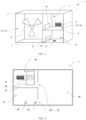
- Figure 1 shows a schematic representation of the outdoor unit (1) and the different chambers created by the partition plates.
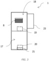
- Figure 2 shows a back view of the outdoor unit (1).
- Figure 3 shows a side view of the outdoor unit (1).
DETAILED DESCRIPTION OF THE INVENTION
-
The invention is further described by the following non-limiting examples which further illustrate the invention, and are not intended to, nor should they be interpreted to, limit the scope of the invention.
-
The present invention concerns an outdoor unit for a heat pump system, which unit is provided with a partitioned interior volume. Each of the chambers created by said partitions is advantageously allocated to one or more functional elements. In particular, the partitions divide the internal volume of the outdoor unit in an electrical component chamber, a machine chamber and an air-sending device chamber. The object of the present invention is to provide an outdoor unit which eliminates the risk of explosion or combustion due to refrigerant deflagrations, while maintaining adequate ventilation of all internal elements, thus preventing overheating of the same.
-
Unless otherwise defined, all terms used in disclosing the invention, including technical and scientific terms, have the meaning as commonly understood by one of ordinary skill in the art to which this invention belongs. By means of further guidance, term definitions are included to better appreciate the teaching of the present invention.
-
As used herein, the following terms have the following meanings:
"A", "an", and "the" as used herein refers to both singular and plural referents unless the context clearly dictates otherwise. By way of example, "a compartment" refers to one or more than one compartment.
-
"Comprise", "comprising", and "comprises" and "comprised of" as used herein are synonymous with "include", "including", "includes" or "contain", "containing", "contains" and are inclusive or open-ended terms that specifies the presence of what follows e.g. component and do not exclude or preclude the presence of additional, non-recited components, features, element, members, steps, known in the art or disclosed therein.
-
Furthermore, the terms first, second, third and the like in the description and in the claims, are used for distinguishing between similar elements and not necessarily for describing a sequential or chronological order, unless specified. It is to be understood that the terms so used are interchangeable under appropriate circumstances and that the embodiments of the invention described herein are capable of operation in other sequences than described or illustrated herein.
-
The recitation of numerical ranges by endpoints includes all numbers and fractions subsumed within that range, as well as the recited endpoints.
-
Whereas the terms "one or more" or "at least one", such as one or more or at least one member(s) of a group of members, is clear per se, by means of further exemplification, the term encompasses inter alia a reference to any one of said members, or to any two or more of said members, such as, e.g., any ≥3, ≥4, ≥5, ≥6 or ≥ 7 etc. of said members, and up to all said members.
-
Unless otherwise defined, all terms used in disclosing the invention, including technical and scientific terms, have the meaning as commonly understood by one of ordinary skill in the art to which this invention belongs. By means of further guidance, definitions for the terms used in the description are included to better appreciate the teaching of the present invention. The terms or definitions used herein are provided solely to aid in the understanding of the invention.
-
Reference throughout this specification to "one embodiment" or "an embodiment" means that a particular feature, structure or characteristic described in connection with the embodiment is included in at least one embodiment of the present invention. Thus, appearances of the phrases "in one embodiment" or "in an embodiment" in various places throughout this specification are not necessarily all referring to the same embodiment, but may. Furthermore, the particular features, structures or characteristics may be combined in any suitable manner, as would be apparent to a person skilled in the art from this disclosure, in one or more embodiments. Furthermore, while some embodiments described herein include some but not other features included in other embodiments, combinations of features of different embodiments are meant to be within the scope of the invention, and form different embodiments, as would be understood by those in the art. For example, in the following claims, any of the claimed embodiments can be used in any combination.
-
With as a goal illustrating better the properties of the invention the following presents, as an example and limiting in no way other potential applications, a description of a number of preferred embodiments is provided based on the invention, wherein:
- FIG. 1 shows a schematic representation of the outdoor unit (1) for a heat pump system, and the different chambers created by the partition plates. The outdoor unit (1), which uses a refrigerant having a characteristic of flammability, combustibility and/or explosiveness, comprises:
- a. a bottom plate (2) and a front casing part (3), a back casing part (4), top casing part (5), left casing part (6) and a right casing part (7) defining a housing (9) of the outdoor unit (1);
- b. a first partition plate (10) mounted to the bottom plate (2) so as to extend upward in the housing (9), and internally dividing the housing in at least a first part and a second part (11, 12);
- c. a second partition plate (13) mounted to a face of the first partition plate (10), extending in the second part (12) of the housing (9) parallel to the bottom plate (2), and dividing the second part (12) in at least a third part and a fourth part (14, 15), wherein said third part (14) is positioned below said fourth part (15);
- d. an air-sending device chamber (16) formed in the housing (9) in the first part (11) of the housing.
-
The outdoor unit (1) is configured to have a machine chamber formed (17) in the third part (14) of the housing, and an electrical component chamber (18) formed in the fourth part (15) of the housing, said electrical component chamber (18) accommodating a PCB with a processing unit that controls the heat pump system. This arrangement of the main elements of the outdoor unit allows for the sensitive control elements, particularly the PCB and the processing unit, to be placed away from the heat bearing/emitting elements of said unit. In this way any contact between any refrigerant possibly escaping from said refrigerant carrying element and any potential sources of ignition, provided by any of the elements in the electrical component chamber (18), is advantageously avoided. The risk of explosion is thus advantageously avoided. A fourth opening (21) is provided in the housing at the machine chamber (17), connecting the machine chamber (17) to the outside of the housing (9). In this embodiment, the fourth opening (21) is provided in the bottom plate (2). This permits not only the evacuation of any refrigerant that may leak from any of the elements inside the machine chamber (17), but allows also the ingress of air, thus increasing the cooling of the aforementioned elements e.g. compressor. Since the refrigerants typically used in air-conditioning and heat pumps are heavier than air, the location of the fourth opening (21) at a lower position will advantageously prevent any buildup of any leaked refrigerant inside the machine chamber (17). Figure 1 further shows an air sending device (22) located inside the air-sending device chamber (16), in this case, said device is a fan for generating an airflow. A second and third opening (19, 20) are shown on the first partition plate (10) and respectively located near the bottom of the electrical component chamber (18) and the machine chamber (17). The second opening (19) is advantageously located adjacent the second partition plate (13) and the third opening is located adjacent to the bottom plate (2). In this way, the heavier than air refrigerant will tend to converge the bottom of the electrical component chamber (18) and the machine chamber (17), and leave through the second and third openings (19. 20) before being forced out of the unit (1) by the air sending device (22). Other embodiments will include more than one fan. The fan permits forcing air through or around any refrigerant bearing elements, but also other elements requiring cooling, such as but not limited to, at least one heat sink (not shown) coupled to electrical components. The fan may have a single or a reversible rotation direction. In this way, if the outdoor unit (1) is exposed to wind from multiple sides, the rotation of the fan can be reversed in order to displace air in substantially the same direction as the direction of the wind, thus increasing the air flow through the unit.
-
FIG. 2 shows a back view of the outdoor unit (1). A first opening (8) is shown formed in the housing (9) at the electrical component chamber (18), connecting said electrical component chamber (18) with the outside of the housing (9). This first opening (8), provides an escape route for heat and any refrigerant which may reach the electrical component chamber (18), and in the most severe situation, the first opening serves as a pressure relief outlet should any refrigerant reach the electrical component chamber (18) and ignite. A terminal (26) for connecting a power cable is shown arranged in a terminal space inside a terminal housing (23) separated from the electric component chamber (18). In this way, the terminal is arranged in a space separated from the electrical component chamber, which further prevents the leaked refrigerant from reaching the terminal (26) and thus precluding the ignition of any leaked refrigerant. A second and third opening (19, 20) are shown on the first partition plate (10) and respectively located near the bottom of the electrical component chamber (18) and the machine chamber (17). The second opening (19) is advantageously located adjacent the second partition plate (13) and the third opening is located adjacent to the bottom plate (2). In this way, the heavier than air refrigerant will tend to converge the bottom of the electrical component chamber (18) and the machine chamber (17), and leave through the second and third openings (19. 20) before being forced out of the unit (1) by the air sending device (22).
-
In an embodiment, a second opening is formed in the first partition plate at the electrical component chamber, connecting said electrical component chamber with the first part of the housing. This second opening allows for electrical communication between the electrical component chamber and air-sending device chamber by means of cables, thereby reducing the number of exposed cables on the outside of the unit, advantageously making such unit more compact and easier to install. By preference the first and the second opening are provided with a cable gland equipped with a seal or gasket, in this way allowing for electrical cables to reach the outside of the electrical component chamber while maintaining the airtightness of said chamber. The outdoor unit (1) is shown further comprising a refrigerant input port (24) for supplying the refrigerant to the outdoor unit (1), and a refrigerant output port (25) for evacuating the refrigerant from the outdoor unit (1). Said refrigerant input port and said refrigerant output port are situated within the machine chamber (17) and at an external wall of the housing (9) defining said machine chamber (17), at the rear face of the machine chamber (17). By preference, no piping connected to any such port traverses the electrical component chamber (18). In this way, the refrigerant piping inside the outdoor unit (1) is advantageously isolated from the electrical component chamber (17). Furthermore, the locations of the ports (24, 25) are advantageously located such that installation of said unit is made easier.
-
FIG.3 shows a side view of the outdoor unit (1). The figure shows a third opening (20) that is provided in the first partition plate (10) at the machine chamber (17), connecting said machine chamber (17) with the first part (11) of the housing (9). In this way, any refrigerant leaking from any of the elements in the machine chamber (17) can be advantageously evacuated to the air-sending device chamber (16) and out of the outdoor unit (1) by means of the air-sending device (22). Figure 3 shows an alternative location of the first opening (8). Like in figure 2, also in the embodiment shown in figure 3, the terminal (26 not shown) is provided located on a rear face of the outdoor unit (1), also sealed from an outdoor space by or with a terminal housing (23).
-
In other embodiments, fourth opening (21) is provided in the housing at the machine chamber (17), connecting the machine chamber (17) to the outside of the housing (9). The fourth opening (21) is provided in the bottom plate (2). This permits not only the evacuation of any refrigerant that may leak from any of the elements inside the machine chamber (17), but allows also the ingress of air, thus increasing the cooling of the aforementioned elements e.g. compressor. Since the refrigerants typically used in air-conditioning and heat pumps are heavier than air, the location of the fourth opening (21) at a lower position will advantageously prevent any buildup of any leaked refrigerant inside the machine chamber (17).
-
In other embodiments (not shown), The terminal housing (23) positioned within the housing (9) adhered to one of the outer casing parts, sealed from the outside space and the chambers within the housing (9). By avoiding add-on parts and making use of free space within the housing (9), restrictions for the placement of the unit being physical or visual are reduced.
-
In other embodiments (not shown) according to the invention, the terminal (26) is arranged on a top face or a lateral face of the housing (9) of the outdoor unit, and wherein said terminal space is also sealed from an outdoor space by or with a terminal housing (23). This configuration advantageously permits the placement of the outdoor unit (1) closer to the wall of a building, should the frontal projection of said unit from said building be an issue.
-
In an embodiment (not shown), the machine chamber (17) and/or the air-sending device chamber (16) houses all refrigerant-carrying and refrigerant-processing systems. In this way, should any refrigerant leak from any of the refrigerant-carrying elements, said leaked refrigerant is forced out by the draft created by the air-sending device (23). Another advantage of this configurations is the added cooling effect on elements such as the motor and the compressor provided by said draft.
-
In an embodiment (not shown), the outdoor unit comprising a compressor, a heat source-side heat exchanger, an expansion means, a load-side heat exchanger and refrigerant piping for circulating the refrigerant by coupling said compressor, said heat source-side heat exchanger, said expansions means and said load-side heat exchanger to each other, wherein each of said compressor, said heat source-side heat exchanger, said expansion means, said load-side heat exchanger and said refrigerant piping are positioned within the machine chamber. In this way, at least heating, possibly cooling, of any indoor spaces reached by the heat pump system can have their temperature controlled by means of heat medium piping, thereby preventing refrigerant piping from entering said indoor spaces. Furthermore, this configuration of the outdoor unit, advantageously, permits cooling and ventilating all refrigerant-bearing elements of the heat pump system using the air sending device.
-
In an embodiment, the electrical component chamber (18) further accommodates a power module for controlling an inverter electric circuit. This advantageously permits regulating temperature by controlling the speed of the compressor. The presence of an inverter unit advantageously permits a more efficient use of energy, as well as, direct connection to direct current power sources, such as solar panels, furthering the energy saving capabilities of the outdoor unit.
-
In an embodiment, the outdoor unit further comprises a heat sink for cooling the inverter power module, wherein the heat sink is exposed to the air-sending device chamber. In this way, the temperature of the electrical component chamber is kept from rising to an excessive level. This permits avoiding damage to the electrical components inside the electrical component chamber.
-
It is supposed that the present invention is not restricted to any form of realization described previously and that some modifications can be added to the presented example of fabrication without reappraisal of the appended claims. For example, the present invention has been described referring to outdoor unit for a heat pump, but it is clear that the invention can be applied to common air conditioning installations for instance or to any other installations requiring an outdoor unit for compressing and cooling a refrigerant.
List of numbered items:
-
- 1
- outdoor unit
- 2
- bottom plate
- 3
- front casing part
- 4
- back casing part
- 5
- top casing part
- 6
- left casing part
- 7
- right casing part
- 8
- first opening
- 9
- housing
- 10
- first partition plate
- 11
- first part
- 12
- second part
- 13
- second partition plate
- 14
- third part
- 15
- fourth part
- 16
- air-sending device chamber
- 17
- machine chamber
- 18
- electrical component chamber
- 19
- second opening
- 20
- third opening
- 21
- fourth opening
- 22
- air-sending device
- 23
- terminal cover
- 24
- refrigerant input port
- 25
- refrigerant output port
- 26
- terminal