EP4560193A1 - Burner - Google Patents
Burner Download PDFInfo
- Publication number
- EP4560193A1 EP4560193A1 EP24189654.7A EP24189654A EP4560193A1 EP 4560193 A1 EP4560193 A1 EP 4560193A1 EP 24189654 A EP24189654 A EP 24189654A EP 4560193 A1 EP4560193 A1 EP 4560193A1
- Authority
- EP
- European Patent Office
- Prior art keywords
- cover
- head
- flame
- hole
- gas
- Prior art date
- Legal status (The legal status is an assumption and is not a legal conclusion. Google has not performed a legal analysis and makes no representation as to the accuracy of the status listed.)
- Pending
Links
Images








Classifications
-
- F—MECHANICAL ENGINEERING; LIGHTING; HEATING; WEAPONS; BLASTING
- F23—COMBUSTION APPARATUS; COMBUSTION PROCESSES
- F23D—BURNERS
- F23D14/00—Burners for combustion of a gas, e.g. of a gas stored under pressure as a liquid
- F23D14/02—Premix gas burners, i.e. in which gaseous fuel is mixed with combustion air upstream of the combustion zone
- F23D14/04—Premix gas burners, i.e. in which gaseous fuel is mixed with combustion air upstream of the combustion zone induction type, e.g. Bunsen burner
- F23D14/06—Premix gas burners, i.e. in which gaseous fuel is mixed with combustion air upstream of the combustion zone induction type, e.g. Bunsen burner with radial outlets at the burner head
- F23D14/065—Premix gas burners, i.e. in which gaseous fuel is mixed with combustion air upstream of the combustion zone induction type, e.g. Bunsen burner with radial outlets at the burner head with injector axis inclined to the burner head axis
-
- F—MECHANICAL ENGINEERING; LIGHTING; HEATING; WEAPONS; BLASTING
- F23—COMBUSTION APPARATUS; COMBUSTION PROCESSES
- F23D—BURNERS
- F23D14/00—Burners for combustion of a gas, e.g. of a gas stored under pressure as a liquid
- F23D14/02—Premix gas burners, i.e. in which gaseous fuel is mixed with combustion air upstream of the combustion zone
- F23D14/04—Premix gas burners, i.e. in which gaseous fuel is mixed with combustion air upstream of the combustion zone induction type, e.g. Bunsen burner
- F23D14/06—Premix gas burners, i.e. in which gaseous fuel is mixed with combustion air upstream of the combustion zone induction type, e.g. Bunsen burner with radial outlets at the burner head
-
- F—MECHANICAL ENGINEERING; LIGHTING; HEATING; WEAPONS; BLASTING
- F23—COMBUSTION APPARATUS; COMBUSTION PROCESSES
- F23D—BURNERS
- F23D14/00—Burners for combustion of a gas, e.g. of a gas stored under pressure as a liquid
- F23D14/02—Premix gas burners, i.e. in which gaseous fuel is mixed with combustion air upstream of the combustion zone
-
- F—MECHANICAL ENGINEERING; LIGHTING; HEATING; WEAPONS; BLASTING
- F23—COMBUSTION APPARATUS; COMBUSTION PROCESSES
- F23D—BURNERS
- F23D14/00—Burners for combustion of a gas, e.g. of a gas stored under pressure as a liquid
- F23D14/46—Details
-
- F—MECHANICAL ENGINEERING; LIGHTING; HEATING; WEAPONS; BLASTING
- F23—COMBUSTION APPARATUS; COMBUSTION PROCESSES
- F23D—BURNERS
- F23D14/00—Burners for combustion of a gas, e.g. of a gas stored under pressure as a liquid
- F23D14/46—Details
- F23D14/62—Mixing devices; Mixing tubes
-
- F—MECHANICAL ENGINEERING; LIGHTING; HEATING; WEAPONS; BLASTING
- F23—COMBUSTION APPARATUS; COMBUSTION PROCESSES
- F23D—BURNERS
- F23D14/00—Burners for combustion of a gas, e.g. of a gas stored under pressure as a liquid
- F23D14/46—Details
- F23D14/62—Mixing devices; Mixing tubes
- F23D14/64—Mixing devices; Mixing tubes with injectors
-
- F—MECHANICAL ENGINEERING; LIGHTING; HEATING; WEAPONS; BLASTING
- F24—HEATING; RANGES; VENTILATING
- F24C—DOMESTIC STOVES OR RANGES ; DETAILS OF DOMESTIC STOVES OR RANGES, OF GENERAL APPLICATION
- F24C3/00—Stoves or ranges for gaseous fuels
- F24C3/08—Arrangement or mounting of burners
- F24C3/085—Arrangement or mounting of burners on ranges
-
- F—MECHANICAL ENGINEERING; LIGHTING; HEATING; WEAPONS; BLASTING
- F23—COMBUSTION APPARATUS; COMBUSTION PROCESSES
- F23D—BURNERS
- F23D2207/00—Ignition devices associated with burner
-
- F—MECHANICAL ENGINEERING; LIGHTING; HEATING; WEAPONS; BLASTING
- F23—COMBUSTION APPARATUS; COMBUSTION PROCESSES
- F23D—BURNERS
- F23D2900/00—Special features of, or arrangements for burners using fluid fuels or solid fuels suspended in a carrier gas
- F23D2900/14—Special features of gas burners
- F23D2900/14062—Special features of gas burners for cooking ranges having multiple flame rings
-
- F—MECHANICAL ENGINEERING; LIGHTING; HEATING; WEAPONS; BLASTING
- F23—COMBUSTION APPARATUS; COMBUSTION PROCESSES
- F23D—BURNERS
- F23D2900/00—Special features of, or arrangements for burners using fluid fuels or solid fuels suspended in a carrier gas
- F23D2900/14—Special features of gas burners
- F23D2900/14063—Special features of gas burners for cooking ranges having one flame ring fed by multiple venturis
Definitions
- the present disclosure relates to a burner, and more specifically, a burner with a simplified flow channel structure for flow of gas.
- a burner emits a flame and generally receives gas from an external source and ignites the gas to generate a flame.
- the burner may be installed in a cooking appliance.
- the burner may be used in a gas range or a cooktop of a combined cooking appliance that uses both gas and electricity, and may receive gas from an external source and combust the gas to generate a flame.
- the burner may be composed of two flame generation portions, and each of the two flame generation portions generally generates a flame having a ring shape.
- the two flame generation portions may generate an inner flame in a small ring shape and an outer flame in a large ring shape surrounding the small ring shape, respectively.
- the burner is provided with multiple gas injection holes, a plurality of pipes connecting the external source and the gas injection holes of the burner to each other should be provided.
- the burner of the above-described structure has a complicated structure to form a gas flow path, making the overall structure of the burner complicated. Therefore, due to the complicated structure, the gas does not flow smoothly, burner performance deteriorates, and a manufacturing cost increases.
- a purpose of the present disclosure is to provide a burner with a structure that improves performance and saves a production cost.
- a purpose of the present disclosure is to provide a burner with a structure that simplifies a path through which gas flows.
- a purpose of the present disclosure is to provide a burner with a structure that smoothly guides the flow of gas.
- a burner according to one embodiment includes a body; a cover disposed on top of the body and coupled to the body to define a mixing tube in which gas and air flow and are mixed with each other; and a head disposed on top of the cover and configured to generate a flame, wherein the head includes: a first flame generation portion disposed in a central area of the head and a second flame generation portion disposed in an outer area of the head.
- the body, the cover, and the head are configured such that: the gas discharged from the mixing tube flows through the cover and flows to the central area of the cover, and then is divided into portions in the central area of the cover, and then one portion thereof flows into the first flame generation portion, and the other one portion thereof flows to the outer area of the cover and flows into the second flame generation portion.
- the burner may be configured such that the gas discharged from the single mixing tube may be supplied into the first flame generation portion and the second flame generation portion in a divided manner.
- the head may include a spreading hole which connected to the second guide tube.
- the gas may flow through the spreading hole.
- the head may include a gas spreading portion through which the gas having flowed through the spreading hole spreads.
- the gas spreading portion may be a space surrounded with the upper surface of the head and the second flame generation portion, and the gas spreading portion may extend along a circumference of the head.
- the upper surface of the head may have an inclined spreading surface disposed at a position where the spreading hole and the gas spreading portion may be connected to each other.
- the inclined spreading surface may contact each of both opposing ends of the spreading hole, and may be inclined in a circumferential or radial direction of the head.
- the gas flowing along the inclined spreading surface may be spread uniformly throughout the gas spreading portion.
- the gas that has flowed through the through-hole may flow from the outer area of the head to the central area of the head through the second guide tube and then may be divided into the portions.
- One of the portions thereof may reach the first flame generation portion and may be injected through the first flame hole, and may be burned.
- the other of the portions of the gas may flow from the central area of the head to the outer area of the head again through the second guide tube and flows through the spreading hole, and then, may reach the second flame generation portion, and may be injected through the second flame hole and may be burned.
- an overall structure of the burner according to an embodiment of the present disclosure may be simplified. Furthermore, the burner according to an embodiment of the present disclosure may be connected to an external source through a single pipe. This simple structure allows for smooth flow of the gas inside the burner, improves burner performance, and saves a manufacturing cost of the burner.
- the gas flowing into the gas spreading portion through the spreading hole flows further upwardly, the gas may be guided along the inclined spreading surface so as to smoothly spread into the gas spreading portion and then be uniformly distributed throughout the gas spreading portion.
- the second flame generation portion may receive a uniform supply of the gas in its circumferential direction and thus generate a uniform flame in its circumferential direction.
- the gas discharged from the single mixing tube may be divided into the portions which may be respectively supplied to the plurality of flame generation portions radially spaced apart from each other in the burner. Due to this structure, the flow channels for gas supply to the flame generation portions may be integrated with each other.
- the gas may be fed to the burner using a single supply pipe, and the flow channel structure in the burner may be simplified.
- first, second, third, and so on may be used herein to describe various elements, components, regions, layers and/or sections, these elements, components, regions, layers and/or sections should not be limited by these terms. These terms are used to distinguish one element, component, region, layer or section from another element, component, region, layer or section. Thus, a first element, component, region, layer or section described under could be termed a second element, component, region, layer or section.
- a and/or B means A, B, or A and B, unless otherwise specified, and "C to D” means C inclusive to D inclusive unless otherwise specified.
- a burner according to an embodiment may be used in a gas range or a cooktop of a combined cooking appliance that uses both gas and electricity, and may receive gas from an external source and combust the gas to generate a flame.
- the burner may be composed of two flame generation portions, and each of the two flame generation portions generally generates a flame having a ring shape.
- the two flame generation portions may generate an inner flame in a small ring shape and an outer flame in a large ring shape surrounding the small ring shape, respectively.
- the burner is provided with multiple gas injection holes, a plurality of pipes connecting the external source and the gas injection holes of the burner to each other should be provided.
- the burner of the above-described structure has a complicated structure to form a gas flow path, making the overall structure of the burner complicated. Therefore, due to the complicated structure, the gas does not flow smoothly, burner performance deteriorates, and a manufacturing cost increases.
- the burner according to an embodiment has a structure to solve the above-mentioned problems, and the burner according to an embodiment is described in detail below.
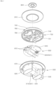
- FIG. 1 is a perspective view showing a burner according to one embodiment.
- FIG. 2 is a side view of FIG. 1 .
- FIG. 3 is a rear view of FIG. 1 .
- the burner according to an embodiment may include a body 500, a cover 600, head 700, an inner cap 820, and an outer cap 810.
- the body 500 may constitute a lower portion of the burner and may be connected to an external source through a pipe so that the body may receive gas required for combustion from the external source.
- the cover 600 may be disposed on a top of the body 500 and may be coupled to the body 500 to define a mixing tube 501 in which gas and air flow and are mixed with each other.
- the cover 600 and the body 500 are manufactured separately from each other. However, in another embodiment, the cover 600 and the body 500 may be integrated into a single body.
- the mixing tube 501 may be a space in the burner.
- the gas flowing thereto from the external source and the air flowing into the burner from a surrounding around the burner may meet and be mixed with each other in the mixing tube 501.
- the gas may be mixed with air and thus may receive oxygen from the air necessary for combustion and thus may be burned in the head 700.
- the mixing tube 501 may be formed by combining the body 500 and the cover 600 with each other.
- the body 500 may constitute (approximately) a lower half of the mixing tube 501, while the cover 600 may constitute (approximately) an upper half of the mixing tube 501.
- the head 700 may be disposed on top of the cover 600, and the flame may be generated in the head 700.
- the head 700 may be coupled to the cover 600 to form a path through which gas flowing into the head 700 and the cover 600 through the body 500 flows.
- the gas flow path formed by combining the header and the cover 600 with each other may distribute the gas to a first flame generation portion 710 and a second flame generation portion 720, which are described in detail below.
- the inner cap 820 may cover a top of the first flame generation portion 710 where the flame may be generated, and may control a spread direction of the flame so that the flame is directed outwardly in the radial direction of the head 700.
- the outer cap 810 may cover a top of the second flame generation portion 720 where the flame may be generated, and may control the spread direction of the flame so that the flame is directed outwardly in the radial direction of the head 700.
- FIG. 4 is an exploded top perspective view of FIG. 1 .
- FIG. 5 is an exploded bottom perspective view of FIG. 1 .
- the head 700 may include a flame generation portion. In the flame generation portion, while gas is discharged outwardly of the burner, the gas is ignited by a spark plug (not shown), thereby generating a flame.
- the head 700 may include the first flame generation portion 710 and the second flame generation portion 720 where the flame may be generated.
- the first flame generation portion 710 may be disposed in the central area of the head 700.
- a plurality of first flame holes 711 may be defined in the first flame generation portion 710 and may be arranged along a circumference thereof.
- the second flame generation portion 720 may be disposed in the outer area of the head 700 and may be disposed to surround the first flame generation portion 710.
- a plurality of second flame holes 721 may be defined in the second flame generation portion 720 and may be arranged along a circumference thereof. Therefore, when the flame may be generated in the burner, inner and outer ring-shaped flames may be generated in a double manner.
- the gas flowing inside the burner may be discharged through the first flame hole 711 and the second flame hole 721.
- a flame may be generated at the outlet of each of the first flame hole 711 and the second flame hole 721, such that the flame may be maintained while the gas is discharged.
- the first flame generation portion 710 and the second flame generation portion 720 may be separate components and may be spaced apart from each other. Therefore, gas needs to be individually supplied to each of the first flame generation portion 710 and the second flame generation portion 720.
- one mixing tube 501 may be used, and gas flowing thereto from one pipe may flow through the single mixing tube 501.
- the gas discharged from one mixing tube 501 should flow into the first flame generation portion 710 and the second flame generation portion 720, which are spaced apart from each other. For this reason, inside the burner, a flow channel needs to be formed to distribute the gas discharged from the mixing tube 501 to each of the first flame generation portion 710 in the central area and the second flame generation portion 720 in the outer area.
- the gas discharged from the mixing tube 501 may flow through the cover 600, and may flow to the central area of the cover 600, and may be divided into portions and then one thereof may flow into the first flame generation portion 710, and the other thereof may flow to the outer area of the cover 600 and may flow into the second flame generation portion 720.
- the gas discharged from the mixing tube 501 may flow through cover 600 and reach an outer area of an upper surfaced of the cover 600. Then, the gas may flow from the outer area of the cover 600 to the central area of the cover 600 and may be divided into the portions. One thereof may flow from the central area of the cover 600 through the head 700 and may reach an upper surface of the head 700, and may flow into the first flame generation portion 710 in the central area of the head 700.
- the other of the portions may flow from the central area to the outer area of a space on the upper surface of the cover 600, and may flow through the head 700, and may reach the upper surface of the head 700, and may flow into the second flame generation portion 720 in the outer area of the head 700.
- the gas flowing into one common mixing tube 501 may be divided into the two portions inside the burner while flowing through the flow channel formed in the burner, and then the two portions may flow into the first flame generation portion 710 and the second flame generation portion 720, respectively.
- an overall structure of the burner according to an embodiment of the present disclosure may be simplified. Furthermore, the burner according to an embodiment of the present disclosure may be connected to an external source through a single pipe. This simple structure allows for smooth flow of the gas inside the burner, improves burner performance, and saves a manufacturing cost of the burner.
- FIG. 6 is a side cross-sectional view of the burner.
- flow of the gas is indicated using a solid arrow.
- flow of air flowing into the burner from the surroundings is indicated using a hidden line arrow.
- the body 500 may include an injection portion 530 and an air receiving portion 540.
- the injection portion 530 may be formed on one side of the body 500, and a gas injection hole 531 may be defined in the injection portion 530.
- the gas injection hole 531 may be formed to extend through the injection portion 530, and may have an inlet connected to a pipe connected to the external source that supplies gas.
- the injection portion 530, the air receiving portion 540 and the mixing tube 501 may be arranged in a straight line. Due to this structure, the gas having flowed through the injection portion 530 may smoothly flow through the air receiving portion 540 and the mixing tube 501.
- the gas injection hole 531 may be formed in the injection portion 530 so as to extend through the injection portion 530.
- the air receiving portion 540 may be disposed between an inlet of the mixing tube 501 and an outlet of the injection portion 530. A space into which air is introduced and stored may be formed in the air receiving portion 540.
- an air guide 701 may protrude downwardly from the head 700 and may cover the space of the air receiving portion 540.
- the air guide 701 may be formed in a generally "U" shape so as to be combined with the air receiving portion 540 to form a space into which air flows.
- the air guide 701 may cover the space of the air receiving portion 540, but may be coupled to the air receiving portion 540 to form a hole into which surrounding air flows in a rear side of the burner. Through the hole, air around the burner may flow into the space of the air receiving portion 540.
- An inlet of the gas injection hole 531 may be relatively wide and an outlet thereof may be relatively narrow.
- the outlet of the gas injection hole 531 may be provided with an orifice, so that the gas flowing into the body 500 through the gas injection hole 531 may be injected at a very high speed from the outlet of the gas injection hole 531.
- the gas injected from the outlet of the gas injection hole 531 may flow into the mixing tube 501 without being dispersed due to its very high flow speed. At this time, the gas may meet the air flowing into the air receiving portion 540 while flowing through the air receiving portion 540, and, at the same time, the air may flow into the mixing tube 501.
- the gas may be mixed with air which has been introduced into the air receiving portion 540, and then the mixture of the gas and the air may be discharged from the mixing tube 501.
- the gas may be mixed with the air in the mixing tube 501 and may be mixed with oxygen in the air.
- the mixture when the mixture is ignited by the spark plug, the mixture may be combusted.
- the mixing tube 501 may be , for example, a Venturi tube.
- the Venturi tube may be formed so that a cross-sectional area of each of the inlet and the outlet thereof is relatively large, and a cross-sectional area of a central area thereof is relatively narrow.
- the gas flow speed is the fastest in the mixing tube 501, such that the pressure may be lowered in the central area.
- the mixing tube 501 may be the Venturi tube.
- the pressure in the neck area is lower than that of an area adjacent thereto.
- the air in the space of the air receiving portion 540 which has a relatively high pressure may smoothly flow into the mixing tube 501 due to the pressure difference and thus may be mixed with the gas in the mixing tube.
- FIG. 7 is a perspective view showing the body 500 and the cover 600 of the burner.
- FIG. 8 is an exploded view of FIG. 7 .
- FIG. 9 is a top view of FIG. 7 .
- FIG. 10 is a bottom view of FIG. 7 .
- FIG. 11 is a perspective view of the body 500.
- FIG. 12 is a top view of FIG. 11 .
- the body 500 may include a lower cell 510 and a first guide tube 520.
- the lower cell 510 may be depressed from an upper surface of the body 500 into the body 500 and may constitute a lower portion of the mixing tube 501.
- the lower cell 510 may constitute (approximately) the half of the mixing tube 501.
- the depressed space of the lower cell 510 constituting the mixing tube 501 may be deeper than a depth of the half of the mixing tube 501.
- the first guide tube 520 may be connected to the outlet of the mixing tube 501 and may have two portions be connected to the outlet of the mixing tube 501 and extending in the circumferential direction of the body 500 and respectively in opposite directions. A portion of the first guide tube 520 may be closed with the cover 600, and the gas may flow in the first guide tube 520. A top of the first guide tube 520 may be closed with the cover 600 to form a gas flow path.
- the first guide tube 520 may be a space connected to the outlet of the mixing tube 501, and may change the flow direction of the gas discharged from the mixing tube 501 to an upward direction.
- the gas discharged from the mixing tube 501 may flow upward along the first guide tube 520 and may flow into the space on the upper surface of the cover 600.
- the body 500 may include a cover receiving groove 550, a first spark plug receiving hole 560, and an extension panel 570.
- the cover receiving groove 550 may be depressed from the upper surface of the body 500 into the body, and may have a shape corresponding to that of the cover 600 so that the cover 600 is received therein.
- a hole into which fastening means such as a bolt is fastened may be formed in a bottom surface defining the cover receiving groove 550, and a corresponding hole thereto may be formed in the cover 600 so that the cover 600 may be coupled to the body 500 using the fastening means. Since the cover 600 is seated in the cover receiving groove 550, the cover 600 may be accurately positioned at a designated position of the body 500.
- the first spark plug receiving hole 560 may be formed at a position overlapping with the cover 600, and the spark plug may be inserted and mounted in the first spark plug receiving hole 560.
- the cover 600 may have a second spark plug receiving hole 650 defined therein into which the spark plug is inserted at a position corresponding to the first spark plug receiving hole 560.
- the first spark plug receiving hole 560 may be disposed adjacent to the first flame generating portion 710 disposed in the central area of the burner.
- the first flame generation portion 710 may be ignited first and the second flame generation portion 720 may be ignited later.
- the first spark plug receiving hole 560 may be disposed adjacent to the second flame generation portion 720 disposed in the outer area of the burner.
- the second flame generation portion 720 may be ignited first and the first flame generation portion 710 may be ignited later.
- the extension panel 570 may surround the cover receiving groove 550 and extend in a circumferential direction of the body 500.
- the extension panel 570 may generally be provided in a disk form. Holes into which the fastening means are inserted may be formed in the extension panel 570.
- the burner may be mounted on a gas range or a combined cooking appliance by coupling the extension panel 570 to the gas range or the cooktop of the combined cooking appliance using the fastening means.
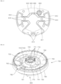
- FIG. 13 is a perspective view of the cover 600.
- FIG. 14 is a bottom view of FIG. 13 .
- FIG. 15 is a top view of FIG. 13 .
- the cover 600 may have a smaller planar area than that of the body 500. As described above, the cover 600 may be seated in the cover receiving groove 550 of the body 500 and may be coupled to the cover 600 using the fastening means.
- the cover 600 may include a through-hole 610 formed at a position that overlaps at least a portion of the first guide tube 520.
- the gas may flow through the through-hole 610.
- the through-hole 610 through which the gas may flow may be formed in the cover 600 at a portion overlapping at least the inclined guide surface 121.
- the gas may flow upwardly along the first guide tube 520 and may flow through the cover 600 through the through-hole 610 and may flow into the space on the upper surface of the cover 600.
- the cover 600 may include the upper cell 620 constituting the mixing tube 501.
- the upper cell 620 may be formed to protrude downwardly toward the body 500, and may have an inner space defined therein so as to be depressed upwardly from a lower surface thereof into the upper cell 620.
- the inner space may constitute an upper portion of the mixing tube 501.
- the upper cell 620 may constitute (approximately) a half of the mixing tube 501. However, the upper cell 620 may be inserted into a groove defined in the lower cell 510 of the body 500 to define the mixing tube 501.
- the upper cell 620 may be formed integrally with the cover 600. However, in another embodiment, the upper cell 620 may be formed as a separate structure from the cover 600. Furthermore, in still another embodiment, the upper cell 620 may be formed integrally with the lower cell 510.
- the burner may include a second guide tube 630.
- the second guide tube 630 may be formed by combining the cover 600 and the head 700 with each other and may provide a space in which the gas flowing to the space from the body 500 may flow from the outer area of the head 700 to the central area thereof.
- the gas may be divided into the portions such that the portions of the gas may be respectively supplied to the first flame generation portion 710 and the second flame generation portion 720 which are spaced apart from each other, using one gas injection hole 531 equipped with the orifice and one mixing tube 501.
- the cover 600 may include the through-hole 610 and a lower part 640.
- the through-hole 610 may be connected to the first guide tube 520 and allows gas to flow through therein. The gas may flow through the through-hole 610, and then, a portion thereof may flow into the second guide tube 630, and a remaining portion thereof may flow into the second flame generation portion 720.
- the through-hole 610 may include a pair of through-hole spaced apart from each other in the circumferential direction and extending in the circumferential direction and in the outer area of the cover 600.
- the through-hole 610 may be disposed on a top of the first guide tube 520, and the flow direction of the gas in the first guide tube 520 may be changed rapidly in the through-hole 610.
- the first guide tube 520 may be formed as a relatively large space, and thus an area size of the through-hole 610 may be increased.
- the through-hole 610 may include a pair of through-holes spaced apart from each other in the circumferential direction, while a bridge portion may be disposed between the through-holes 610 to reinforce the rigidity of the cover 600.
- fastening holes may be defined in the bridge portion between the through-holes 610 such that fastening means may be inserted and fastened to the fastening holes.
- the various holes may be efficiently arranged in an entire area of the cover 600.
- the coupling between the cover 600 and the body 500 may be strengthened using the fastening means inserted and fastened to the fastening holes.
- the lower part 640 may be formed so that a portion thereof surrounds the through-hole 610, and may protrude upwardly from the upper surface of the cover 600, and may constitute a lower portion of the second guide tube 630.
- the lower part 640 and an upper part 740 formed on the head 700 may be combined to each other to define the second guide tube 630.
- the lower part 640 may include a first flow channel-defining part 641, a first central part 642, a first outer part 643, and a first connection part 644.
- the first flow channel-defining part 641 may surround the through-hole 610 and may define a flow channel extending from the through-hole 610 to the central area of the cover 600.
- the gas that has flowed through the through-hole 610 and has flowed into the space on the upper surface of the cover may flow from the outer area of the cover 600 to the central area thereof along the first flow channel-defining part 641.
- the first central part 642 may be formed in the central area of the cover 600, may be connected to the first flow channel-defining part 641, and may define a flow channel connected to the first flame generation portion 710.
- the gas may be divided into the portions such that one portion may flow to the first flame generation portion 710 and the remaining portion may flow to the second flame generation portion 720.
- the portion of the gas flowing into the first central part 642 may flow upwardly and may flow into the first flame generation portion 710, while the other portion thereof may flow back to the outer area of the cover 600 along the first connection part 644 and may reach the first outer part 643.
- the first outer part 643 may be disposed in the outer area of the cover 600, may define a flow channel connected to the second flame generation portion 720, and may include a pair of the first outer parts spaced apart from each other in the circumferential direction.
- the gas flowing into the first outer part 643 may flow upwardly and may flow through the spreading hole 730 of the head 700 and to a space on the upper surface of the head and may reach the second flame generation portion 720.
- the first connection part 644 may define a flow channel connecting an inner space of the first outer part 643 and an inner space of the first central part 642 to each other. Since the first outer part 643 includes the pair of first outer parts, the first connection part 644 may include a pair of first connection parts respectively connected to the pair of first outer parts 643.
- the gas flowing into the first flow channel-defining part 641 may flow through the first central part 642 and the first connection part 644 and may flow upwardly in the first outer part 643.
- bottom surfaces of the first flow channel-defining part 641, the first central part 642, and the first connection part 644 may constitute a continuous plane.
- the pair of first outer parts 643 may be formed and arranged symmetrically with each around the center of the cover 600.
- the pair of first connection parts 644 may be formed and arranged symmetrically with each around the center of the cover 600.
- the first outer part 643 may be formed at a position that overlaps a side portion 780 of the head 700 in the vertical direction. Due to this structure, the gas that has reached the first outer part 643 may flow smoothly to the side portion 780 and then reach the second flame generation portion.
- the lower part may include a lower partitioning wall that protrudes upwardly from the upper surface of the cover 600, and the lower partitioning wall may surround the through-hole 610.
- the gas that has flowed through the through-hole 610 may be guided along the lower partitioning wall so as to flow to the first flow channel-defining part 641 and the first central part 642.
- the lower partitioning wall may constitute walls of the first flow channel-defining part 641, the first central part 642, the first outer part 643 and the first connection part 644. That is, the first flow channel-defining part 641, the first central part 642, the first outer part 643, and the first connection part 644 may be constituted with the lower partitioning wall protruding upwardly from the upper surface of the cover 600.
- the cover 600 may include a second spark plug receiving hole 650 into which the spark plug is inserted and mounted.
- the second spark plug receiving hole 650 may be positioned in a position corresponding to the first spark plug receiving hole 560 of the body 500. Therefore, depending on a location of the first spark plug receiving hole 560, the second spark plug receiving hole 650 may be disposed adjacent to the first flame generation portion 710 or adjacent to the second flame generation portion 720.
- FIG. 16 is a perspective view showing the cover 600 and the head 700.
- FIG. 17 is an exploded top perspective view of FIG. 16 .
- FIG. 18 is a bottom perspective view of FIG. 16 .
- FIG. 19 is a top view of FIG. 16 .
- a structure is needed to guide a position of the head 700 so that the head 700 may be disposed in a correct position on the cover 600.
- an insert protrusion 772 may be formed on the head 700, and a protrusion receiving groove 660 may be formed in the cover 600.
- the head 700 When the protrusion 772 of the head 700 is inserted into the protrusion receiving groove 660 of the cover 600, the head 700 may be disposed in the correct position on the cover 600.
- the insert protrusion 772 and the protrusion receiving groove 660 are additionally described below. Hereinafter, the head 700 is described in detail.
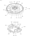
- FIG. 20 is a perspective view of the head 700.
- FIG. 21 is a bottom view of FIG. 20 .
- FIG. 22 is a top view of FIG. 20 .
- FIG. 23 is a view of FIG. 20 in a different direction.
- the head 700 may include a spreading hole 730 and the upper part 740.
- the spreading hole 730 may be connected to the second guide tube 630 and may allow gas to flow therein.
- the gas flowing into the spreading hole 730 may flow into the second flame generation portion 720 and be burned therein.
- the spreading hole 730 may include a pair of spreading holes disposed in the outer area of the head 700 and spaced from each other in the circumferential direction of the head. In the plan view, the spreading hole 730 may be spaced from the through-hole 610 in the circumferential direction of the head.
- the portion of the gas having flowed through the through-hole 610 may flow to the central area of the head 700 along the second guide tube 630.
- the other portion of the gas may flow back to the outer area of the head 700, and may flow through the spreading hole 730, and may spread in the circumferential direction in a space on the upper surface of the head 700, and then may flow into the second flame generation portion 720.
- the upper part 740 may be formed so that a portion thereof surrounds the spreading hole 730, and may protrude downwardly from a lower surface of the head 700, and may be coupled to the lower part 640 to define an upper portion of the second guide tube 630.
- the lower part 640 of the cover 600 and the upper part 740 of the head 700 may be combined with each other to define the second guide tube 630.
- the upper part 740 may include a second flow channel-defining part 741, a second central part 742, a second outer part 743, and a second connection part 744.
- the second flow channel-defining part 741 may cover the through-hole 610 and may define a flow channel extending from the through-hole 610 to the central area of the head 700.
- the gas that has flowed through the through-hole 610 and has flowed into the second flow channel-defining part 741 may flow along the second flow channel-defining part 741 from the outer area of the head 700 to the central area thereof.
- the second central part 742 may be formed in the central area of the head 700, may be connected to the second flow channel-defining part 741, and may define a flow channel connected to the first flame generation portion 710.
- the gas may be divided into the portions such that one portion may flow to the first flame generation portion 710 and a remaining portion may flow to the second flame generation portion 720.
- the portion of the gas flowing into the second central part 742 may flow upwardly and may flow into the first flame generation portion 710. The other portion thereof may flow back to the outer area of the head 700 along the second connection part 744 and may reach the second outer part 743.
- the second outer part 743 may surround the spreading hole 730 and may be disposed in the outer area of the head 700, and may define a flow channel connected to the second flame generation portion 720.
- the second outer part 743 may include a pair of second outer parts spaced apart from each other in the circumferential direction. The gas flowing into the second outer part 743 may flow upwardly and may flow through the spreading hole 730 of the head 700 and may flow along a space on the upper surface of the head 700 and may reach the second flame generation portion 720.
- the second connection part 744 may define a flow channel connecting the inner space of the second outer part 743 and the inner space of the second central part 742. Since the second outer part 743 includes the pair of second outer parts, the second connection part 744 may include a pair of second connection parts respectively connected to the pair of second outer parts 743.
- An opening may be formed in a side surface of the second central part 742, and this opening may be connected to the second outer part 743 through the second connection part 744.
- the pair of second outer parts 743 may be arranged symmetrically around a center of the head 700.
- the pair of second connection parts 744 may be arranged symmetrically around a center of the head 700.
- the upper part 740 may include an upper partitioning wall protruding downwardly from the lower surface of the head 700, and the upper partitioning wall may surround the through-hole 610 formed in the outer area of the cover 600.
- the gas flowing through through-hole 610 may be guided along the upper partitioning wall so as to flow to the second connection part 744 and the second central part 742.
- the upper partitioning wall may constitute walls of the second flow channel-defining part 741, the second central part 742, the second outer part 743, and the second connection part 744. That is, the second flow channel-defining part 741, the second central part 742, the second outer part 743, and the second connection part 744 may be constituted with the upper partitioning wall protruding downwardly from the lower surface of the head 700.
- contact surfaces of the partitioning walls respectively constituting the upper part 740 and the lower part 640 contacting each other may have the same shape.
- the gas that has flowed through the through-hole 610 may flow from the outer area of the head 700 to the central area of the head 700 through the second guide tube 630 and may be divided into the portions in the central area of the head 700.
- One of the portions into the gas has been divided into in the central area of the head 700 may reach the first flame generation portion 710 and may be injected through the first flame hole 711 and may be burned.
- the other of the portions into the gas has been divided into in the central area of the head 700 may flow from the central area of the head 700 to the outer area of the head 700 through the second guide tube 630 and the may flow through spreading hole 730, and then, may reach the second flame generation portion 720, and may be injected through the second flame hole 721 and may be burned.
- the second guide tube 630 may include a first space defined by combining the first flow channel-defining part 641 and the second flow channel-defining part 741 with each other, a second space defined by combining the first central part 642 and the second central part 742 with each other, a third space defined by combining the first connection part 644 and the second connection part 744 with each other, and a fourth space defined by combining the first outer part 643 and the second outer part 743 with each other.
- the gas may flow into the first space in the outer area of the second guide tube 630 and may flow from the first space into the second space and reach the central area of the head 700.
- the gas may be divided into the portions in the second space. One of the portions may flow upwardly directly from the second space and may flow upwardly through a central hole disposed in an upper portion of the central area of the head 700, and may reach the first flame generation portion 710 connected to this central hole.
- the other of the portions of the gas may flow through the third space, and flow into the fourth space in the outer area of the head 700, and may flow upwardly from the fourth space to reach the second flame generation portion 720 in the outer area of the head 700.
- the gas that has flowed through the through-hole 610 may be divided into the two portions in the second guide tube 630. One thereof may reach the first flame generation portion 710 while the other one thereof may reach the second flame generation portion 720.
- the first flame generation portion 710 may be disposed in the central area of the head 700 and may protrude upwardly from the upper surface of the head 700. Furthermore, the second flame generation portion 720 may protrude upwardly from the upper surface of the head 700 in the outer area of the head 700. Accordingly, the second flame generation portion 720 may surround the first flame generation portion 710.
- the head 700 may include a gas spreading portion 750 and a flame propagation portion 760.
- the gas spreading portion 750 may be a space in which the gas flowing through the spreading hole 730 spreads and which is surrounded with the upper surface of the head 700 and the second flame generation portion 720, and may extend along the circumference of the head 700.
- the gas spreading portion 750 may be a space connected to the second flame generation portion 720, and may extend in a ring shape with a constant width and may be positioned inwardly of the second flame generation portion 720. Accordingly, the gas that has flowed through the spreading hole 730 may spread along the gas spreading portion 750 and on the upper surface of the head 700 and flow into the second flame generation portion 720 uniformly in the circumferential direction of the second flame generation portion 720.
- An inclined spreading surface 761 may be disposed at a location adjacent to the spreading hole 730 to facilitate the flow and spread of gas. That is, the inclined spreading surface 761 may be defined on the upper surface of the head 700 and at an area where the spreading hole 730 and the gas spreading portion 750 are connected to each other, and may constitute each of both opposing ends of the spreading hole 730.
- the inclined spreading surface 761 may be inclined in the circumferential or radial direction.
- the inclined spreading surface 761 may be formed on the upper surface of the head 700 so as to be inclined in the circumferential or radial direction. Due to the inclined spreading surface 761, a planar area size of the spreading hole 730 may increases as the spreading hole 730 extends upwardly.
- the gas flowing into the gas spreading portion 750 through the spreading hole 730 may flows further upwardly, the gas may be guided along the inclined spreading surface 761 so as to smoothly spread into the gas spreading portion 750 and then be uniformly distributed throughout the gas spreading portion 750.
- the second flame generation portion 720 may receive a uniform supply of the gas in its circumferential direction and thus generate a uniform flame in its circumferential direction.
- the flame propagation portion 760 may occupy a partial area of the gas spreading portion 750 such that the gas spreading portion 750 may be discontinuous at the flame propagation portion 760.
- the flame propagation portion 760 may be a space in which the flame propagates between the first flame generation portion 710 and the second flame generation portion 720.
- the flame may be generated in the flame propagation portion 760, and the flame may flow from the first flame generation portion 710 to the second flame generation portion 720 or from the second flame generation portion 720 to the first flame generation portion 710 through the flame propagation portion 760.
- the head 700 may include a spreading portion-defining protrusion 762 and a propagation portion-defining protrusion 763.
- the spreading portion-defining protrusion 762 may be disposed between the first flame generation portion 710 and the second flame generation portion 720, protrude upwardly from the upper surface of the head 700, extend in the circumferential direction of the head 700, and surround the gas spreading portion 750.
- the gas spreading portion 750 may be a space surrounded with the second flame generation portion 720, the upper surface of the head 700, the spreading portion-defining protrusion 762, and the outer cap 810.
- the propagation portion-defining protrusion 763 may protrude upwardly from the upper surface of the head 700 and may include a pair of propagation portion-defining protrusions respectively disposed on both opposing sides of the flame propagation portion 760 to define the flame propagation portion 760.
- the propagation portion-defining protrusion 763 may isolate the gas spreading portion 750 and the flame propagation portion 760 from each other.
- the propagation portion-defining protrusion 763 may have a through-hole extending therethrough, so that the gas in the gas spreading portion 750 is discharged to the flame propagation portion 760 through this through-hole.
- the flame may be generated at an outlet of the through-hole, and then, this flame may propagate from the first flame generation portion 710 to the second flame generation portion 720 through the flame propagation portion 760 or vice versa.
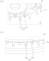
- FIG. 24 is an enlarged view of a portion 58 of FIG. 23 .
- FIG. 24 shows a portion of the first flame generation portion 710.
- FIG. 25 is an enlarged view of a portion 59 of FIG. 23 .
- FIG. 25 shows a portion of the second flame generation portion 720.
- the flame generation portion may include the flame hole through which gas is sprayed. A flame may be generated at an outlet of the flame hole.
- the first flame generation portion 710 may include the first flame hole 711, and the second flame generation portion 720 may include the second flame hole 721.
- the first flame hole 711 or the second flame hole 721 may be depressed into the upper end of the first flame generation portion 710 or the second flame generation portion 720.
- the first flame hole 711 may be covered with the inner cap 820, and the second flame hole 721 may be covered with the outer cap 810 so that a top of each of the first and second flame holes may be blocked.
- Depression depths of neighboring flame holes in the first flame generation portion 710 or the second flame generation portion 720 may be different from each other.
- the first flame generation portion 710 may have deep first flame holes 711a and shallow first flame holes 711b arranged alternately with each other along the circumference.
- the deep second flame holes 721a and the shallow second flame hole s721b may be alternately arranged each other along the circumference of the second flame generation portion 720.
- the depression depth of the flame hole may be proportional to an amount of gas discharged to the outside through the flame hole. Furthermore, a size and a length of the flame may be proportional to the discharged gas amount through the flame hole.
- the deeper the depression depth of the flame hole the larger the size of the flame generated at the outlet of the flame hole.
- a likelihood at which adjacent flames merge with each other increases.
- a relatively deep flame hole may be disposed between relatively shallow flame holes. Due to this structure, a spacing between large flames highly likely to merge with each other may be increased, and the relatively small flame may be placed therebetween, such that the merging between neighboring flames may be effectively suppressed.
- the flame generation portion is formed only to have relatively shallow flame holes, the gas amount discharged from the flame generation portion is small, so that the burner cannot generate sufficient fire power.
- a plurality of relatively deep flame holes may be arranged such that the gas may be sufficiently discharged to the outside through the flame holes.
- FIG. 26 is a perspective view showing a state in which the outer cap 810 and the inner cap 820 are installed on the head 700.
- FIG. 27 is a cross-sectional view of FIG. 26.
- FIG. 28 is an enlarged view of a portion 62 of FIG. 27 .
- FIG. 29 is a perspective view showing the inner cap 820.
- the burner may include the outer cap 810 and the inner cap 820 that cover the flame generation portion.
- the outer cap 810 may be disposed on an upper end of each of the second flame generation portion 720 and the spreading portion-defining protrusion 762 and may cover the gas spreading portion 750.
- the outer cap 810 may be disposed on the head 700 and cover an upper end of the gas spreading portion 750.
- the outer cap 810 may have an inclined cross sectional shape.
- the outer cap 810 may be formed so that its cross-sectional shape is gradually inclined upwardly as the outer cap extends outwardly in the radial direction.
- the head 700 may include a core 770, the side portion 789, a first support 791 and a second support 792.
- the core 770 may be disposed in the central area of the head 700, and the first flame generation portion 710 may be formed at an upper end of the core.
- the inner cap 820 may be disposed on the upper end of the core 770.
- the side portion 789 occupies the outer area of the head 700 and the gas spreading portion 750 may be defined in the side portion 789.
- the core 770 and the side portion 789 may be arranged to be spaced apart from each other, and may be connected to each other via the first and second supports 791 and 792 and the pair of second connection parts 744.
- the first support 791 may connect the core 770 and the side portion 780 to each other and may meet the inner end of the flame propagation portion 760.
- the second support 792 may connect the core 770 and the side portion 780 to each other, and may be opposite to the first support 791 around the core 770.
- the pair of second connection parts 744, the first support 791 and the second support 792 may connect the core 770 and the side portion 780 to each other and may be spaced from each other in the circumferential direction. A space may be defined between each of the pair of second connection parts 744 and each of the first and second supports 791 and 792.
- the first flame generation portion 710 may be formed to protrude from an outer area of the core 770. In the core 770 and in an area inwardly of the first flame generation portion 710, a space may be defined where portions of the gas flowing into the core 770 through the second guide tube 630 are merged with each other.
- the core 770 may include a plurality of guide protrusions 771 that protrude upward and are spaced apart from each other in the circumferential direction, and guides a mounting position of the inner cap 820.
- Each of the plurality of guide protrusions 771 may be disposed between adjacent ones of the plurality of first flame holes 711.
- the inner cap 820 may include a guide ring 821 which protrudes downwardly and is formed to surround the guide protrusions 771 and contacts the guide protrusions 771.
- the guide protrusions 771 may be formed on the core 770, and the guide ring 821 may be formed on the inner cap 820.
- the guide protrusion 771 may include a plurality of guide protrusions spaced apart from each other in the circumferential direction.
- the guide protrusions 771 may be located inwardly of the guide ring 821 so as to contact the guide ring. The position of the inner cap 820 may be guided along the guide protrusions 771, and thus may not deviate laterally from the core 770.
- the inner cap 820 may be stably disposed in the designed position on the upper end of core 770 and may maintain its position.
- the core 770 may include a supporter 773 that contacts a lower surface of the inner cap 820 and supports the inner cap 820.
- the supporter 773 may be formed to be inclined gradually upwardly as the support extends inwardly of the core 770.
- the inner cap 820 may be disposed on an upper surface of the supporter 773.
- the supporter 773 may be disposed inwardly of the guide protrusion 771.
- the upper surface of the supporter 773 may extend in a generally straight line, while a lower surface of the supporter may be generally curved.
- the gas discharged from the flame holes of the first flame generation portion 710 or the second flame generation portion 720 may be mixed with the secondary air around the flame generation portion to increase combustion efficiency. Since the second flame generation portion 720 is disposed in the outer area of the burner, the gas discharged from the second flame hole 721 may actively contact the surrounding secondary air.
- the first flame generation portion 710 may be disposed on the core 770 disposed in the central area of the burner, a contact area thereof in contact with the surrounding air may be reduced due to the outer cap 810 and other structures.
- a vertical level of the first flame generation portion 710 may be higher than that of the spreading portion-defining protrusion 762. Due to this structure, a vertical level of the first flame generation portion 710 may be higher than that of the outer cap 810. Thus, a contact area of the first flame generation portion 710 with the surrounding air may be increased.
- the first flame generation portion 710 smoothly contacts the surrounding air, such that the gas discharged from the first flame generation portion 710 smoothly receives the surrounding secondary air, and thus incomplete combustion due to insufficient supply of the secondary air may be suppressed.
- the core 770 may include the insert protrusion 772 protruding downwardly and inserted into the groove defined in the cover 600.
- the cover 600 may include the protrusion receiving groove 660 depressed from the upper surface of the cover into the cover, and formed in an area corresponding to the insertion protrusion 772.
- the insert protrusion 772 may be inserted into the protrusion receiving groove 660.
- the insert protrusion 772 may include at least one insert protrusion 772.
- the protrusion receiving groove 660 may include at least one protrusion receiving groove 660.
- the core 770 may be provided with the insert protrusion 772, and the cover 600 may be provided with the protrusion receiving groove 660.
- the head 700 may be stably disposed at the designed position on an upper end of the cover 600 and may maintain its position.
- FIG. 30 is a diagram for illustrating flow of gas in a burner according to one embodiment.
- the gas discharged from one mixing tube 501 may flow into the first guide tube 520 and the second guide tube 630.
- the gas may be divided into the two portions flowing in the opposite directions and in the circumferential direction. Then, the two portions may flow through the cover. Then, a portion of each of the two portions may flow to the second flame generation portion 720 disposed in the outer area of the burner, and a remaining portion thereof may flow to the first flame generation portion 710 disposed in the central area of the burner.
- the gas may be mixed with the primary air. Then, the mixture of the gas and the air may be discharged from the mixing tube 501, and then flow into the first guide tube 520.
- the gas flowing into the first guide tube 520 may flow into the second guide tube 630 through the through-hole 610.
- the gas flowing into the second guide tube 630 may flow to the central area of the head 700 and may be divided into the portions in the central area of the head 700.
- One of the portions of the gas in the central area of the head 700 may flow upwardly immediately and may flow into the first flame generation portion 710, and may be discharged through the first flame hole 711 and may be burned to generate a flame.
- the other of the portions of the gas in the central area of the head 700 may flow to the outer area of the head 700 through the space defined by the first connection part 644 and the second connection part 744 and may flow upwardly and flow through the spreading hole 730. Then, the gas may spread along the gas spreading portion 750 and may flow into the second flame generation portion 720 and may flow evenly along the circumference of the second flame generation portion 720 disposed in the outer area of the head 700, and may be discharged through the second flame hole 721 and may be burned to generate a flame.
- the gas discharged from the single mixing tube 501 may be divided into the portions which may be respectively supplied to the plurality of flame generation portions radially spaced apart from each other in the burner. Due to this structure, the flow channels for gas supply to the flame generation portions may be integrated with each other. The gas may be fed to the burner using a single supply pipe, and the flow channel structure in the burner may be simplified.
Landscapes
- Engineering & Computer Science (AREA)
- Chemical & Material Sciences (AREA)
- Combustion & Propulsion (AREA)
- Mechanical Engineering (AREA)
- General Engineering & Computer Science (AREA)
- Gas Burners (AREA)
Abstract
A burner includes a body; a cover disposed on top of the body and coupled to the body to define a mixing tube in which gas and air flow and are mixed with each other; and a head disposed on top of the cover and configured to generate a flame, wherein the head includes: a first flame generation portion disposed in a central area of the head and a second flame generation portion disposed in an outer area of the head. The body, the cover, and the head are configured such that: the gas discharged from the mixing tube flows through the cover and flows to the central area of the cover, and then is divided into portions in the central area of the cover, and then one thereof flows into the first flame generation portion, and the other thereof flows to the outer area of the cover and flows into the second flame generation portion.
Description
- The present disclosure relates to a burner, and more specifically, a burner with a simplified flow channel structure for flow of gas.
- The contents as described in this Background Section simply provides background information on the present disclosure and does not constitute a prior art.
- A burner emits a flame and generally receives gas from an external source and ignites the gas to generate a flame. The burner may be installed in a cooking appliance.
- The burner may be used in a gas range or a cooktop of a combined cooking appliance that uses both gas and electricity, and may receive gas from an external source and combust the gas to generate a flame.
- The burner may be composed of two flame generation portions, and each of the two flame generation portions generally generates a flame having a ring shape. The two flame generation portions may generate an inner flame in a small ring shape and an outer flame in a large ring shape surrounding the small ring shape, respectively.
- In this structure, it is common that separate gas flow paths are respectively formed for the two flame generation portions to deliver combusted gas between the two flame generation portions spaced apart from each other. In this general structure, a plurality of gas flow paths independent of each other should be provided in the burner.
- Furthermore, since the burner is provided with multiple gas injection holes, a plurality of pipes connecting the external source and the gas injection holes of the burner to each other should be provided.
- The burner of the above-described structure has a complicated structure to form a gas flow path, making the overall structure of the burner complicated. Therefore, due to the complicated structure, the gas does not flow smoothly, burner performance deteriorates, and a manufacturing cost increases.
- To solve this problem, it is necessary to manufacture a burner that has a single gas injection hole and a gas flow path connected to the hole and divided into to a plurality of flame generation portions spaced apart from each other.
- A purpose of the present disclosure is to provide a burner with a structure that improves performance and saves a production cost.
- Furthermore, a purpose of the present disclosure is to provide a burner with a structure that simplifies a path through which gas flows.
- Furthermore, a purpose of the present disclosure is to provide a burner with a structure that smoothly guides the flow of gas.
- Purposes according to the present disclosure are not limited to the above-mentioned purpose. Other purposes and advantages according to the present disclosure that are not mentioned may be understood based on following descriptions, and may be more clearly understood based on embodiments according to the present disclosure. Further, it will be easily understood that the purposes and advantages according to the present disclosure may be realized using means shown in the claims or combinations thereof.
- The invention is specified by the independent claim. Preferred embodiments are defined in the dependent claims. A burner according to one embodiment includes a body; a cover disposed on top of the body and coupled to the body to define a mixing tube in which gas and air flow and are mixed with each other; and a head disposed on top of the cover and configured to generate a flame, wherein the head includes: a first flame generation portion disposed in a central area of the head and a second flame generation portion disposed in an outer area of the head.
- The body, the cover, and the head are configured such that: the gas discharged from the mixing tube flows through the cover and flows to the central area of the cover, and then is divided into portions in the central area of the cover, and then one portion thereof flows into the first flame generation portion, and the other one portion thereof flows to the outer area of the cover and flows into the second flame generation portion.
- Accordingly, the burner may be configured such that the gas discharged from the single mixing tube may be supplied into the first flame generation portion and the second flame generation portion in a divided manner.
- The head may include a spreading hole which connected to the second guide tube. The gas may flow through the spreading hole.
- The head may include a gas spreading portion through which the gas having flowed through the spreading hole spreads. The gas spreading portion may be a space surrounded with the upper surface of the head and the second flame generation portion, and the gas spreading portion may extend along a circumference of the head.
- The upper surface of the head may have an inclined spreading surface disposed at a position where the spreading hole and the gas spreading portion may be connected to each other. The inclined spreading surface may contact each of both opposing ends of the spreading hole, and may be inclined in a circumferential or radial direction of the head. The gas flowing along the inclined spreading surface may be spread uniformly throughout the gas spreading portion.
- The gas that has flowed through the through-hole may flow from the outer area of the head to the central area of the head through the second guide tube and then may be divided into the portions.
- One of the portions thereof may reach the first flame generation portion and may be injected through the first flame hole, and may be burned. The other of the portions of the gas may flow from the central area of the head to the outer area of the head again through the second guide tube and flows through the spreading hole, and then, may reach the second flame generation portion, and may be injected through the second flame hole and may be burned.
- In the burner according to the present disclosure, compared to a structure in which the external source is connected to a plurality of pipes, and a plurality of gas flow paths respectively connected to the plurality of pipes and the flame generation portions may be provided independently of each other, an overall structure of the burner according to an embodiment of the present disclosure may be simplified. Furthermore, the burner according to an embodiment of the present disclosure may be connected to an external source through a single pipe. This simple structure allows for smooth flow of the gas inside the burner, improves burner performance, and saves a manufacturing cost of the burner.
- Furthermore, in the burner according to the present disclosure, while the gas flowing into the gas spreading portion through the spreading hole flows further upwardly, the gas may be guided along the inclined spreading surface so as to smoothly spread into the gas spreading portion and then be uniformly distributed throughout the gas spreading portion. As a result, the second flame generation portion may receive a uniform supply of the gas in its circumferential direction and thus generate a uniform flame in its circumferential direction.
- Furthermore, in the burner according to the present disclosure, the gas discharged from the single mixing tube may be divided into the portions which may be respectively supplied to the plurality of flame generation portions radially spaced apart from each other in the burner. Due to this structure, the flow channels for gas supply to the flame generation portions may be integrated with each other. The gas may be fed to the burner using a single supply pipe, and the flow channel structure in the burner may be simplified.
- In addition to the above-mentioned effects, the specific effects of the present disclosure are described below along with the description of the specific details for carrying out the present disclosure.
-
-
FIG. 1 is a perspective view showing a burner according to one embodiment. -
FIG. 2 is a side view ofFIG. 1 . -
FIG. 3 is a rear view ofFIG. 1 . -
FIG. 4 is an exploded top perspective view ofFIG. 1 . -
FIG. 5 is an exploded bottom perspective view ofFIG. 1 . -
FIG. 6 is a side cross-sectional view of a burner. -
FIG. 7 is a perspective view showing a body and a cover of a burner. -
FIG. 8 is an exploded view ofFIG. 7 . -
FIG. 9 is a top view ofFIG. 7 . -
FIG. 10 is a bottom view ofFIG. 7 . -
FIG. 11 is a perspective view of a body. -
FIG. 12 is a top view ofFIG. 11 . -
FIG. 13 is a perspective view of a cover. -
FIG. 14 is a bottom view ofFIG. 13 . -
FIG. 15 is a top view ofFIG. 13 . -
FIG. 16 is a perspective view showing a cover and a head. -
FIG. 17 is an exploded top perspective view ofFIG. 16 . -
FIG. 18 is a bottom perspective view ofFIG. 16 . -
FIG. 19 is a top view ofFIG. 16 . -
FIG. 20 is a perspective view of a head. -
FIG. 21 is a bottom view ofFIG. 20 . -
FIG. 22 is a top view ofFIG. 20 . -
FIG. 23 is a view ofFIG. 20 in a different direction. -
FIG. 24 is an enlarged view of a portion 24 ofFIG. 23 . -
FIG. 25 is an enlarged view of a portion 25 ofFIG. 23 . -
FIG. 26 is a perspective view showing a state in which an outer cap and an inner cap are installed on a head. -
FIG. 27 is a cross-sectional view ofFIG. 26 . -
FIG. 28 is an enlarged view of a portion 28 ofFIG. 27 . -
FIG. 29 is a perspective view showing an inner cap. -
FIG. 30 is a diagram for illustrating flow of gas in a burner according to one embodiment. - The above-mentioned purposes, features, and advantages will be described in detail later with reference to the attached drawings. In describing the present disclosure, when it is determined that a detailed description of the publicly known technology related to the present disclosure may unnecessarily obscure the gist of the present disclosure, the detailed description thereof will be omitted. Hereinafter, a preferred embodiment according to the present disclosure will be described in detail with reference to the attached drawings. In the drawings, identical reference numerals are used to indicate identical or similar components.
- It will be understood that, although the terms "first", "second", "third", and so on may be used herein to describe various elements, components, regions, layers and/or sections, these elements, components, regions, layers and/or sections should not be limited by these terms. These terms are used to distinguish one element, component, region, layer or section from another element, component, region, layer or section. Thus, a first element, component, region, layer or section described under could be termed a second element, component, region, layer or section.
- As used herein, the singular constitutes "a" and "an" are intended to include the plural constitutes as well, unless the context clearly indicates otherwise.
- It will be further understood that the terms "comprise", "comprising", "include", and "including" when used in this specification, specify the presence of the stated features, integers, operations, elements, and/or components, but do not preclude the presence or addition of one or more other features, integers, operations, elements, components, and/or portions thereof.
- Throughout the present disclosure, "A and/or B" means A, B, or A and B, unless otherwise specified, and "C to D" means C inclusive to D inclusive unless otherwise specified.
- A burner according to an embodiment may be used in a gas range or a cooktop of a combined cooking appliance that uses both gas and electricity, and may receive gas from an external source and combust the gas to generate a flame.
- The burner may be composed of two flame generation portions, and each of the two flame generation portions generally generates a flame having a ring shape. The two flame generation portions may generate an inner flame in a small ring shape and an outer flame in a large ring shape surrounding the small ring shape, respectively.
- In this structure, it is common that separate gas flow paths are respectively formed for the two flame generation portions to deliver combusted gas between the two flame generation portions spaced apart from each other. In this general structure, a plurality of gas flow paths independent of each other should be provided in the burner.
- Furthermore, since the burner is provided with multiple gas injection holes, a plurality of pipes connecting the external source and the gas injection holes of the burner to each other should be provided.
- The burner of the above-described structure has a complicated structure to form a gas flow path, making the overall structure of the burner complicated. Therefore, due to the complicated structure, the gas does not flow smoothly, burner performance deteriorates, and a manufacturing cost increases.
- To solve this problem, it is necessary to manufacture a burner that has a single gas injection hole and a gas flow path connected to the hole and divided into to a plurality of flame generation portions spaced apart from each other.
- The burner according to an embodiment has a structure to solve the above-mentioned problems, and the burner according to an embodiment is described in detail below.
-
FIG. 1 is a perspective view showing a burner according to one embodiment.FIG. 2 is a side view ofFIG. 1 .FIG. 3 is a rear view ofFIG. 1 . The burner according to an embodiment may include abody 500, acover 600,head 700, aninner cap 820, and anouter cap 810. - The
body 500 may constitute a lower portion of the burner and may be connected to an external source through a pipe so that the body may receive gas required for combustion from the external source. Thecover 600 may be disposed on a top of thebody 500 and may be coupled to thebody 500 to define a mixingtube 501 in which gas and air flow and are mixed with each other. - In the illustrated embodiment, the
cover 600 and thebody 500 are manufactured separately from each other. However, in another embodiment, thecover 600 and thebody 500 may be integrated into a single body. - The mixing
tube 501 may be a space in the burner. The gas flowing thereto from the external source and the air flowing into the burner from a surrounding around the burner may meet and be mixed with each other in the mixingtube 501. The gas may be mixed with air and thus may receive oxygen from the air necessary for combustion and thus may be burned in thehead 700. - The mixing
tube 501 may be formed by combining thebody 500 and thecover 600 with each other. Thebody 500 may constitute (approximately) a lower half of the mixingtube 501, while thecover 600 may constitute (approximately) an upper half of the mixingtube 501. - The
head 700 may be disposed on top of thecover 600, and the flame may be generated in thehead 700. Thehead 700 may be coupled to thecover 600 to form a path through which gas flowing into thehead 700 and thecover 600 through thebody 500 flows. The gas flow path formed by combining the header and thecover 600 with each other may distribute the gas to a firstflame generation portion 710 and a secondflame generation portion 720, which are described in detail below. - The
inner cap 820 may cover a top of the firstflame generation portion 710 where the flame may be generated, and may control a spread direction of the flame so that the flame is directed outwardly in the radial direction of thehead 700. Theouter cap 810 may cover a top of the secondflame generation portion 720 where the flame may be generated, and may control the spread direction of the flame so that the flame is directed outwardly in the radial direction of thehead 700. -
FIG. 4 is an exploded top perspective view ofFIG. 1 .FIG. 5 is an exploded bottom perspective view ofFIG. 1 . Thehead 700 may include a flame generation portion. In the flame generation portion, while gas is discharged outwardly of the burner, the gas is ignited by a spark plug (not shown), thereby generating a flame. - The
head 700 may include the firstflame generation portion 710 and the secondflame generation portion 720 where the flame may be generated. The firstflame generation portion 710 may be disposed in the central area of thehead 700. A plurality of first flame holes 711 may be defined in the firstflame generation portion 710 and may be arranged along a circumference thereof. - The second
flame generation portion 720 may be disposed in the outer area of thehead 700 and may be disposed to surround the firstflame generation portion 710. A plurality of second flame holes 721 may be defined in the secondflame generation portion 720 and may be arranged along a circumference thereof. Therefore, when the flame may be generated in the burner, inner and outer ring-shaped flames may be generated in a double manner. - The gas flowing inside the burner may be discharged through the
first flame hole 711 and thesecond flame hole 721. When the gas is ignited, a flame may be generated at the outlet of each of thefirst flame hole 711 and thesecond flame hole 721, such that the flame may be maintained while the gas is discharged. - The first
flame generation portion 710 and the secondflame generation portion 720 may be separate components and may be spaced apart from each other. Therefore, gas needs to be individually supplied to each of the firstflame generation portion 710 and the secondflame generation portion 720. In an embodiment, onemixing tube 501 may be used, and gas flowing thereto from one pipe may flow through thesingle mixing tube 501. - Therefore, the gas discharged from one
mixing tube 501 should flow into the firstflame generation portion 710 and the secondflame generation portion 720, which are spaced apart from each other. For this reason, inside the burner, a flow channel needs to be formed to distribute the gas discharged from the mixingtube 501 to each of the firstflame generation portion 710 in the central area and the secondflame generation portion 720 in the outer area. - In the burner according to an embodiment of the present disclosure, the gas discharged from the mixing
tube 501 may flow through thecover 600, and may flow to the central area of thecover 600, and may be divided into portions and then one thereof may flow into the firstflame generation portion 710, and the other thereof may flow to the outer area of thecover 600 and may flow into the secondflame generation portion 720. - In other words, the gas discharged from the mixing
tube 501 may flow throughcover 600 and reach an outer area of an upper surfaced of thecover 600. Then, the gas may flow from the outer area of thecover 600 to the central area of thecover 600 and may be divided into the portions. One thereof may flow from the central area of thecover 600 through thehead 700 and may reach an upper surface of thehead 700, and may flow into the firstflame generation portion 710 in the central area of thehead 700. - The other of the portions may flow from the central area to the outer area of a space on the upper surface of the
cover 600, and may flow through thehead 700, and may reach the upper surface of thehead 700, and may flow into the secondflame generation portion 720 in the outer area of thehead 700. - Due to this structure, the gas flowing into one
common mixing tube 501 may be divided into the two portions inside the burner while flowing through the flow channel formed in the burner, and then the two portions may flow into the firstflame generation portion 710 and the secondflame generation portion 720, respectively. - Therefore, compared to a structure in which the external source is connected to a plurality of pipes, and a plurality of gas flow paths respectively connected to the plurality of pipes and the flame generation portions are provided independently of each other, an overall structure of the burner according to an embodiment of the present disclosure may be simplified. Furthermore, the burner according to an embodiment of the present disclosure may be connected to an external source through a single pipe. This simple structure allows for smooth flow of the gas inside the burner, improves burner performance, and saves a manufacturing cost of the burner.
-
FIG. 6 is a side cross-sectional view of the burner. In drawings as described below, flow of the gas is indicated using a solid arrow. Furthermore, inFIG. 6 , the flow of air flowing into the burner from the surroundings is indicated using a hidden line arrow. - The
body 500 may include aninjection portion 530 and anair receiving portion 540. Theinjection portion 530 may be formed on one side of thebody 500, and agas injection hole 531 may be defined in theinjection portion 530. Thegas injection hole 531 may be formed to extend through theinjection portion 530, and may have an inlet connected to a pipe connected to the external source that supplies gas. - The
injection portion 530, theair receiving portion 540 and the mixingtube 501 may be arranged in a straight line. Due to this structure, the gas having flowed through theinjection portion 530 may smoothly flow through theair receiving portion 540 and the mixingtube 501. - The
gas injection hole 531 may be formed in theinjection portion 530 so as to extend through theinjection portion 530. - The
air receiving portion 540 may be disposed between an inlet of the mixingtube 501 and an outlet of theinjection portion 530. A space into which air is introduced and stored may be formed in theair receiving portion 540. In one example, anair guide 701 may protrude downwardly from thehead 700 and may cover the space of theair receiving portion 540. Theair guide 701 may be formed in a generally "U" shape so as to be combined with theair receiving portion 540 to form a space into which air flows. - The
air guide 701 may cover the space of theair receiving portion 540, but may be coupled to theair receiving portion 540 to form a hole into which surrounding air flows in a rear side of the burner. Through the hole, air around the burner may flow into the space of theair receiving portion 540. - An inlet of the
gas injection hole 531 may be relatively wide and an outlet thereof may be relatively narrow. For example, the outlet of thegas injection hole 531 may be provided with an orifice, so that the gas flowing into thebody 500 through thegas injection hole 531 may be injected at a very high speed from the outlet of thegas injection hole 531. - The gas injected from the outlet of the
gas injection hole 531 may flow into the mixingtube 501 without being dispersed due to its very high flow speed. At this time, the gas may meet the air flowing into theair receiving portion 540 while flowing through theair receiving portion 540, and, at the same time, the air may flow into the mixingtube 501. - While the gas flows through the mixing
tube 501, the gas may be mixed with air which has been introduced into theair receiving portion 540, and then the mixture of the gas and the air may be discharged from the mixingtube 501. In this way, the gas may be mixed with the air in the mixingtube 501 and may be mixed with oxygen in the air. Thus, when the mixture is ignited by the spark plug, the mixture may be combusted. - The mixing
tube 501 may be , for example, a Venturi tube. The Venturi tube may be formed so that a cross-sectional area of each of the inlet and the outlet thereof is relatively large, and a cross-sectional area of a central area thereof is relatively narrow. - Therefore, in a neck area as a narrow cross-sectional area of the central area of the mixing
tube 501, the gas flow speed is the fastest in the mixingtube 501, such that the pressure may be lowered in the central area. - The mixing
tube 501 may be the Venturi tube. Thus, the pressure in the neck area is lower than that of an area adjacent thereto. Thus, the air in the space of theair receiving portion 540 which has a relatively high pressure may smoothly flow into the mixingtube 501 due to the pressure difference and thus may be mixed with the gas in the mixing tube. -
FIG. 7 is a perspective view showing thebody 500 and thecover 600 of the burner.FIG. 8 is an exploded view ofFIG. 7 .FIG. 9 is a top view ofFIG. 7 .FIG. 10 is a bottom view ofFIG. 7 .FIG. 11 is a perspective view of thebody 500.FIG. 12 is a top view ofFIG. 11 . - The
body 500 may include alower cell 510 and afirst guide tube 520. Thelower cell 510 may be depressed from an upper surface of thebody 500 into thebody 500 and may constitute a lower portion of the mixingtube 501. Thelower cell 510 may constitute (approximately) the half of the mixingtube 501. - However, since at least a portion of an
upper cell 620 formed on thecover 600 is received in a depressed space of thelower cell 510, the depressed space of thelower cell 510 constituting the mixingtube 501 may be deeper than a depth of the half of the mixingtube 501. - The
first guide tube 520 may be connected to the outlet of the mixingtube 501 and may have two portions be connected to the outlet of the mixingtube 501 and extending in the circumferential direction of thebody 500 and respectively in opposite directions. A portion of thefirst guide tube 520 may be closed with thecover 600, and the gas may flow in thefirst guide tube 520. A top of thefirst guide tube 520 may be closed with thecover 600 to form a gas flow path. - The
first guide tube 520 may be a space connected to the outlet of the mixingtube 501, and may change the flow direction of the gas discharged from the mixingtube 501 to an upward direction. The gas discharged from the mixingtube 501 may flow upward along thefirst guide tube 520 and may flow into the space on the upper surface of thecover 600. - The
body 500 may include acover receiving groove 550, a first sparkplug receiving hole 560, and anextension panel 570. Thecover receiving groove 550 may be depressed from the upper surface of thebody 500 into the body, and may have a shape corresponding to that of thecover 600 so that thecover 600 is received therein. - A hole into which fastening means such as a bolt is fastened may be formed in a bottom surface defining the
cover receiving groove 550, and a corresponding hole thereto may be formed in thecover 600 so that thecover 600 may be coupled to thebody 500 using the fastening means. Since thecover 600 is seated in thecover receiving groove 550, thecover 600 may be accurately positioned at a designated position of thebody 500. - The first spark
plug receiving hole 560 may be formed at a position overlapping with thecover 600, and the spark plug may be inserted and mounted in the first sparkplug receiving hole 560. In one example, thecover 600 may have a second sparkplug receiving hole 650 defined therein into which the spark plug is inserted at a position corresponding to the first sparkplug receiving hole 560. - In the illustrated embodiment, the first spark
plug receiving hole 560 may be disposed adjacent to the firstflame generating portion 710 disposed in the central area of the burner. In this structure, the firstflame generation portion 710 may be ignited first and the secondflame generation portion 720 may be ignited later. - In another embodiment, the first spark
plug receiving hole 560 may be disposed adjacent to the secondflame generation portion 720 disposed in the outer area of the burner. In this structure, the secondflame generation portion 720 may be ignited first and the firstflame generation portion 710 may be ignited later. - The
extension panel 570 may surround thecover receiving groove 550 and extend in a circumferential direction of thebody 500. Theextension panel 570 may generally be provided in a disk form. Holes into which the fastening means are inserted may be formed in theextension panel 570. - Accordingly, the burner may be mounted on a gas range or a combined cooking appliance by coupling the
extension panel 570 to the gas range or the cooktop of the combined cooking appliance using the fastening means. -
FIG. 13 is a perspective view of thecover 600.FIG. 14 is a bottom view ofFIG. 13 .FIG. 15 is a top view ofFIG. 13 . Thecover 600 may have a smaller planar area than that of thebody 500. As described above, thecover 600 may be seated in thecover receiving groove 550 of thebody 500 and may be coupled to thecover 600 using the fastening means. - The
cover 600 may include a through-hole 610 formed at a position that overlaps at least a portion of thefirst guide tube 520. The gas may flow through the through-hole 610. The through-hole 610 through which the gas may flow may be formed in thecover 600 at a portion overlapping at least the inclined guide surface 121. The gas may flow upwardly along thefirst guide tube 520 and may flow through thecover 600 through the through-hole 610 and may flow into the space on the upper surface of thecover 600. - Furthermore, the
cover 600 may include theupper cell 620 constituting the mixingtube 501. Theupper cell 620 may be formed to protrude downwardly toward thebody 500, and may have an inner space defined therein so as to be depressed upwardly from a lower surface thereof into theupper cell 620. The inner space may constitute an upper portion of the mixingtube 501. - The
upper cell 620 may constitute (approximately) a half of the mixingtube 501. However, theupper cell 620 may be inserted into a groove defined in thelower cell 510 of thebody 500 to define the mixingtube 501. - In the illustrated embodiment, the
upper cell 620 may be formed integrally with thecover 600. However, in another embodiment, theupper cell 620 may be formed as a separate structure from thecover 600. Furthermore, in still another embodiment, theupper cell 620 may be formed integrally with thelower cell 510. - In one example, the burner may include a
second guide tube 630. Thesecond guide tube 630 may be formed by combining thecover 600 and thehead 700 with each other and may provide a space in which the gas flowing to the space from thebody 500 may flow from the outer area of thehead 700 to the central area thereof. - The gas discharged from the
first guide tube 520 may flow to the central area of thehead 700 through thesecond guide tube 630 and may be divided into portions which may be fed to the first and secondflame generation portion - The gas may be divided into the portions such that the portions of the gas may be respectively supplied to the first
flame generation portion 710 and the secondflame generation portion 720 which are spaced apart from each other, using onegas injection hole 531 equipped with the orifice and onemixing tube 501. - The
cover 600 may include the through-hole 610 and alower part 640. In addition to the above description, the through-hole 610 may be connected to thefirst guide tube 520 and allows gas to flow through therein. The gas may flow through the through-hole 610, and then, a portion thereof may flow into thesecond guide tube 630, and a remaining portion thereof may flow into the secondflame generation portion 720. - The through-
hole 610 may include a pair of through-hole spaced apart from each other in the circumferential direction and extending in the circumferential direction and in the outer area of thecover 600. The through-hole 610 may be disposed on a top of thefirst guide tube 520, and the flow direction of the gas in thefirst guide tube 520 may be changed rapidly in the through-hole 610. - Therefore, in order to allow the flow of the gas between the mixing
tube 501 and thesecond guide tube 630 to be smooth, thefirst guide tube 520 may be formed as a relatively large space, and thus an area size of the through-hole 610 may be increased. - If a single through-
hole 610 with a large area size is formed, the rigidity of thecover 600 may be weakened. Therefore, in accordance with an embodiment, the through-hole 610 may include a pair of through-holes spaced apart from each other in the circumferential direction, while a bridge portion may be disposed between the through-holes 610 to reinforce the rigidity of thecover 600. - Furthermore, fastening holes may be defined in the bridge portion between the through-
holes 610 such that fastening means may be inserted and fastened to the fastening holes. Thus, the various holes may be efficiently arranged in an entire area of thecover 600. The coupling between thecover 600 and thebody 500 may be strengthened using the fastening means inserted and fastened to the fastening holes. - The
lower part 640 may be formed so that a portion thereof surrounds the through-hole 610, and may protrude upwardly from the upper surface of thecover 600, and may constitute a lower portion of thesecond guide tube 630. Thelower part 640 and anupper part 740 formed on thehead 700 may be combined to each other to define thesecond guide tube 630. - The
lower part 640 may include a first flow channel-definingpart 641, a firstcentral part 642, a firstouter part 643, and afirst connection part 644. The first flow channel-definingpart 641 may surround the through-hole 610 and may define a flow channel extending from the through-hole 610 to the central area of thecover 600. - The gas that has flowed through the through-
hole 610 and has flowed into the space on the upper surface of the cover may flow from the outer area of thecover 600 to the central area thereof along the first flow channel-definingpart 641. - The first
central part 642 may be formed in the central area of thecover 600, may be connected to the first flow channel-definingpart 641, and may define a flow channel connected to the firstflame generation portion 710. In the firstcentral part 642, the gas may be divided into the portions such that one portion may flow to the firstflame generation portion 710 and the remaining portion may flow to the secondflame generation portion 720. - The portion of the gas flowing into the first
central part 642 may flow upwardly and may flow into the firstflame generation portion 710, while the other portion thereof may flow back to the outer area of thecover 600 along thefirst connection part 644 and may reach the firstouter part 643. - The first
outer part 643 may be disposed in the outer area of thecover 600, may define a flow channel connected to the secondflame generation portion 720, and may include a pair of the first outer parts spaced apart from each other in the circumferential direction. The gas flowing into the firstouter part 643 may flow upwardly and may flow through the spreadinghole 730 of thehead 700 and to a space on the upper surface of the head and may reach the secondflame generation portion 720. - The
first connection part 644 may define a flow channel connecting an inner space of the firstouter part 643 and an inner space of the firstcentral part 642 to each other. Since the firstouter part 643 includes the pair of first outer parts, thefirst connection part 644 may include a pair of first connection parts respectively connected to the pair of firstouter parts 643. - The gas flowing into the first flow channel-defining
part 641 may flow through the firstcentral part 642 and thefirst connection part 644 and may flow upwardly in the firstouter part 643. In order for gas to flow smoothly, bottom surfaces of the first flow channel-definingpart 641, the firstcentral part 642, and thefirst connection part 644 may constitute a continuous plane. - In one example, the pair of first
outer parts 643 may be formed and arranged symmetrically with each around the center of thecover 600. The pair offirst connection parts 644 may be formed and arranged symmetrically with each around the center of thecover 600. - The first
outer part 643 may be formed at a position that overlaps aside portion 780 of thehead 700 in the vertical direction. Due to this structure, the gas that has reached the firstouter part 643 may flow smoothly to theside portion 780 and then reach the second flame generation portion. - The lower part may include a lower partitioning wall that protrudes upwardly from the upper surface of the
cover 600, and the lower partitioning wall may surround the through-hole 610. The gas that has flowed through the through-hole 610 may be guided along the lower partitioning wall so as to flow to the first flow channel-definingpart 641 and the firstcentral part 642. - The lower partitioning wall may constitute walls of the first flow channel-defining
part 641, the firstcentral part 642, the firstouter part 643 and thefirst connection part 644. That is, the first flow channel-definingpart 641, the firstcentral part 642, the firstouter part 643, and thefirst connection part 644 may be constituted with the lower partitioning wall protruding upwardly from the upper surface of thecover 600. - In one example, the
cover 600 may include a second sparkplug receiving hole 650 into which the spark plug is inserted and mounted. The second sparkplug receiving hole 650 may be positioned in a position corresponding to the first sparkplug receiving hole 560 of thebody 500. Therefore, depending on a location of the first sparkplug receiving hole 560, the second sparkplug receiving hole 650 may be disposed adjacent to the firstflame generation portion 710 or adjacent to the secondflame generation portion 720. -
FIG. 16 is a perspective view showing thecover 600 and thehead 700.FIG. 17 is an exploded top perspective view ofFIG. 16 .FIG. 18 is a bottom perspective view ofFIG. 16 .FIG. 19 is a top view ofFIG. 16 . - Foreign substances may remain on the
head 700 due to the use of the burner. Therefore, cleaning of thehead 700 is necessary for hygiene purposes. To clean thehead 700, thehead 700 may be easily removed from the burner. - Therefore, for example, it is necessary to couple the
head 700 and thecover 600 or thebody 500 using the fastening means so that the user may easily remove thehead 700 from the burner using the fastening means when necessary. - A structure is needed to guide a position of the
head 700 so that thehead 700 may be disposed in a correct position on thecover 600. For this guide, aninsert protrusion 772 may be formed on thehead 700, and aprotrusion receiving groove 660 may be formed in thecover 600. - When the
protrusion 772 of thehead 700 is inserted into theprotrusion receiving groove 660 of thecover 600, thehead 700 may be disposed in the correct position on thecover 600. Theinsert protrusion 772 and theprotrusion receiving groove 660 are additionally described below. Hereinafter, thehead 700 is described in detail. -
FIG. 20 is a perspective view of thehead 700.FIG. 21 is a bottom view ofFIG. 20 .FIG. 22 is a top view ofFIG. 20 .FIG. 23 is a view ofFIG. 20 in a different direction. - The
head 700 may include a spreadinghole 730 and theupper part 740. The spreadinghole 730 may be connected to thesecond guide tube 630 and may allow gas to flow therein. The gas flowing into the spreadinghole 730 may flow into the secondflame generation portion 720 and be burned therein. - The spreading
hole 730 may include a pair of spreading holes disposed in the outer area of thehead 700 and spaced from each other in the circumferential direction of the head. In the plan view, the spreadinghole 730 may be spaced from the through-hole 610 in the circumferential direction of the head. - Therefore, the portion of the gas having flowed through the through-
hole 610 may flow to the central area of thehead 700 along thesecond guide tube 630. The other portion of the gas may flow back to the outer area of thehead 700, and may flow through the spreadinghole 730, and may spread in the circumferential direction in a space on the upper surface of thehead 700, and then may flow into the secondflame generation portion 720. - The
upper part 740 may be formed so that a portion thereof surrounds the spreadinghole 730, and may protrude downwardly from a lower surface of thehead 700, and may be coupled to thelower part 640 to define an upper portion of thesecond guide tube 630. Thelower part 640 of thecover 600 and theupper part 740 of thehead 700 may be combined with each other to define thesecond guide tube 630. - The
upper part 740 may include a second flow channel-definingpart 741, a secondcentral part 742, a secondouter part 743, and asecond connection part 744. The second flow channel-definingpart 741 may cover the through-hole 610 and may define a flow channel extending from the through-hole 610 to the central area of thehead 700. - The gas that has flowed through the through-
hole 610 and has flowed into the second flow channel-definingpart 741 may flow along the second flow channel-definingpart 741 from the outer area of thehead 700 to the central area thereof. - The second
central part 742 may be formed in the central area of thehead 700, may be connected to the second flow channel-definingpart 741, and may define a flow channel connected to the firstflame generation portion 710. In the secondcentral part 742, the gas may be divided into the portions such that one portion may flow to the firstflame generation portion 710 and a remaining portion may flow to the secondflame generation portion 720. - The portion of the gas flowing into the second
central part 742 may flow upwardly and may flow into the firstflame generation portion 710. The other portion thereof may flow back to the outer area of thehead 700 along thesecond connection part 744 and may reach the secondouter part 743. - The second
outer part 743 may surround the spreadinghole 730 and may be disposed in the outer area of thehead 700, and may define a flow channel connected to the secondflame generation portion 720. The secondouter part 743 may include a pair of second outer parts spaced apart from each other in the circumferential direction. The gas flowing into the secondouter part 743 may flow upwardly and may flow through the spreadinghole 730 of thehead 700 and may flow along a space on the upper surface of thehead 700 and may reach the secondflame generation portion 720. - The
second connection part 744 may define a flow channel connecting the inner space of the secondouter part 743 and the inner space of the secondcentral part 742. Since the secondouter part 743 includes the pair of second outer parts, thesecond connection part 744 may include a pair of second connection parts respectively connected to the pair of secondouter parts 743. - An opening may be formed in a side surface of the second
central part 742, and this opening may be connected to the secondouter part 743 through thesecond connection part 744. - In one example, the pair of second
outer parts 743 may be arranged symmetrically around a center of thehead 700. The pair ofsecond connection parts 744 may be arranged symmetrically around a center of thehead 700. - The
upper part 740 may include an upper partitioning wall protruding downwardly from the lower surface of thehead 700, and the upper partitioning wall may surround the through-hole 610 formed in the outer area of thecover 600. The gas flowing through through-hole 610 may be guided along the upper partitioning wall so as to flow to thesecond connection part 744 and the secondcentral part 742. - The upper partitioning wall may constitute walls of the second flow channel-defining
part 741, the secondcentral part 742, the secondouter part 743, and thesecond connection part 744. That is, the second flow channel-definingpart 741, the secondcentral part 742, the secondouter part 743, and thesecond connection part 744 may be constituted with the upper partitioning wall protruding downwardly from the lower surface of thehead 700. - To prevent the gas flowing into the
second guide tube 630 from leaking out through a gap between theupper part 740 and thelower part 640, contact surfaces of the partitioning walls respectively constituting theupper part 740 and thelower part 640 contacting each other may have the same shape. - The gas that has flowed through the through-
hole 610 may flow from the outer area of thehead 700 to the central area of thehead 700 through thesecond guide tube 630 and may be divided into the portions in the central area of thehead 700. One of the portions into the gas has been divided into in the central area of thehead 700 may reach the firstflame generation portion 710 and may be injected through thefirst flame hole 711 and may be burned. - The other of the portions into the gas has been divided into in the central area of the
head 700 may flow from the central area of thehead 700 to the outer area of thehead 700 through thesecond guide tube 630 and the may flow through spreadinghole 730, and then, may reach the secondflame generation portion 720, and may be injected through thesecond flame hole 721 and may be burned. - The
second guide tube 630 may include a first space defined by combining the first flow channel-definingpart 641 and the second flow channel-definingpart 741 with each other, a second space defined by combining the firstcentral part 642 and the secondcentral part 742 with each other, a third space defined by combining thefirst connection part 644 and thesecond connection part 744 with each other, and a fourth space defined by combining the firstouter part 643 and the secondouter part 743 with each other. - The gas may flow into the first space in the outer area of the
second guide tube 630 and may flow from the first space into the second space and reach the central area of thehead 700. The gas may be divided into the portions in the second space. One of the portions may flow upwardly directly from the second space and may flow upwardly through a central hole disposed in an upper portion of the central area of thehead 700, and may reach the firstflame generation portion 710 connected to this central hole. - The other of the portions of the gas may flow through the third space, and flow into the fourth space in the outer area of the
head 700, and may flow upwardly from the fourth space to reach the secondflame generation portion 720 in the outer area of thehead 700. - In this way, the gas that has flowed through the through-
hole 610 may be divided into the two portions in thesecond guide tube 630. One thereof may reach the firstflame generation portion 710 while the other one thereof may reach the secondflame generation portion 720. - The first
flame generation portion 710 may be disposed in the central area of thehead 700 and may protrude upwardly from the upper surface of thehead 700. Furthermore, the secondflame generation portion 720 may protrude upwardly from the upper surface of thehead 700 in the outer area of thehead 700. Accordingly, the secondflame generation portion 720 may surround the firstflame generation portion 710. - The
head 700 may include agas spreading portion 750 and aflame propagation portion 760. Thegas spreading portion 750 may be a space in which the gas flowing through the spreadinghole 730 spreads and which is surrounded with the upper surface of thehead 700 and the secondflame generation portion 720, and may extend along the circumference of thehead 700. - The
gas spreading portion 750 may be a space connected to the secondflame generation portion 720, and may extend in a ring shape with a constant width and may be positioned inwardly of the secondflame generation portion 720. Accordingly, the gas that has flowed through the spreadinghole 730 may spread along thegas spreading portion 750 and on the upper surface of thehead 700 and flow into the secondflame generation portion 720 uniformly in the circumferential direction of the secondflame generation portion 720. - An inclined spreading
surface 761 may be disposed at a location adjacent to the spreadinghole 730 to facilitate the flow and spread of gas. That is, the inclined spreadingsurface 761 may be defined on the upper surface of thehead 700 and at an area where the spreadinghole 730 and thegas spreading portion 750 are connected to each other, and may constitute each of both opposing ends of the spreadinghole 730. The inclined spreading surface 761may be inclined in the circumferential or radial direction. - The inclined spreading
surface 761 may be formed on the upper surface of thehead 700 so as to be inclined in the circumferential or radial direction. Due to the inclined spreadingsurface 761, a planar area size of the spreadinghole 730 may increases as the spreadinghole 730 extends upwardly. - Accordingly, while the gas flowing into the
gas spreading portion 750 through the spreadinghole 730 may flows further upwardly, the gas may be guided along the inclined spreadingsurface 761 so as to smoothly spread into thegas spreading portion 750 and then be uniformly distributed throughout thegas spreading portion 750. As a result, the secondflame generation portion 720 may receive a uniform supply of the gas in its circumferential direction and thus generate a uniform flame in its circumferential direction. - The
flame propagation portion 760 may occupy a partial area of thegas spreading portion 750 such that thegas spreading portion 750 may be discontinuous at theflame propagation portion 760. Theflame propagation portion 760 may be a space in which the flame propagates between the firstflame generation portion 710 and the secondflame generation portion 720. The flame may be generated in theflame propagation portion 760, and the flame may flow from the firstflame generation portion 710 to the secondflame generation portion 720 or from the secondflame generation portion 720 to the firstflame generation portion 710 through theflame propagation portion 760. - Therefore, the flame generated in the first
flame generation portion 710 may flow to the secondflame generation portion 720, or conversely, the flame generated in the secondflame generation portion 720 may flow to the firstflame generation portion 710. Accordingly, the flame may always exist in the firstflame generation portion 710 and the secondflame generation portion 720 while the gas is supplied thereto. - When a flame is not ignited or is extinguished in one flame generation portion, the flame of another flame generation portion may flow through the propagation portion, thereby generating a flame in the flame generation portion where there is no flame.
- The
head 700 may include a spreading portion-defining protrusion 762 and a propagation portion-definingprotrusion 763. The spreading portion-defining protrusion 762 may be disposed between the firstflame generation portion 710 and the secondflame generation portion 720, protrude upwardly from the upper surface of thehead 700, extend in the circumferential direction of thehead 700, and surround thegas spreading portion 750. - The
gas spreading portion 750 may be a space surrounded with the secondflame generation portion 720, the upper surface of thehead 700, the spreading portion-defining protrusion 762, and theouter cap 810. - The propagation portion-defining
protrusion 763 may protrude upwardly from the upper surface of thehead 700 and may include a pair of propagation portion-defining protrusions respectively disposed on both opposing sides of theflame propagation portion 760 to define theflame propagation portion 760. The propagation portion-definingprotrusion 763 may isolate thegas spreading portion 750 and theflame propagation portion 760 from each other. - The propagation portion-defining
protrusion 763 may have a through-hole extending therethrough, so that the gas in thegas spreading portion 750 is discharged to theflame propagation portion 760 through this through-hole. The flame may be generated at an outlet of the through-hole, and then, this flame may propagate from the firstflame generation portion 710 to the secondflame generation portion 720 through theflame propagation portion 760 or vice versa. -
FIG. 24 is an enlarged view of aportion 58 ofFIG. 23 .FIG. 24 shows a portion of the firstflame generation portion 710.FIG. 25 is an enlarged view of aportion 59 ofFIG. 23 .FIG. 25 shows a portion of the secondflame generation portion 720. - The flame generation portion may include the flame hole through which gas is sprayed. A flame may be generated at an outlet of the flame hole. The first
flame generation portion 710 may include thefirst flame hole 711, and the secondflame generation portion 720 may include thesecond flame hole 721. - The
first flame hole 711 or thesecond flame hole 721 may be depressed into the upper end of the firstflame generation portion 710 or the secondflame generation portion 720. Thefirst flame hole 711 may be covered with theinner cap 820, and thesecond flame hole 721 may be covered with theouter cap 810 so that a top of each of the first and second flame holes may be blocked. - Depression depths of neighboring flame holes in the first
flame generation portion 710 or the secondflame generation portion 720 may be different from each other. For example, the firstflame generation portion 710 may have deepfirst flame holes 711a and shallowfirst flame holes 711b arranged alternately with each other along the circumference. The deepsecond flame holes 721a and the shallow second flame hole s721b may be alternately arranged each other along the circumference of the secondflame generation portion 720. - The depression depth of the flame hole may be proportional to an amount of gas discharged to the outside through the flame hole. Furthermore, a size and a length of the flame may be proportional to the discharged gas amount through the flame hole.
- Therefore, the deeper the depression depth of the flame hole, the larger the size of the flame generated at the outlet of the flame hole. As the size of the flame increases, a likelihood at which adjacent flames merge with each other increases.
- When the size of the flame becomes larger due to the merging, the gas inside the flame may not contact the air, which may lead to incomplete combustion of the gas. Therefore, it is necessary to suppress the merging to suppress incomplete combustion.
- In an embodiment, a relatively deep flame hole may be disposed between relatively shallow flame holes. Due to this structure, a spacing between large flames highly likely to merge with each other may be increased, and the relatively small flame may be placed therebetween, such that the merging between neighboring flames may be effectively suppressed.
- Further, when the flame generation portion is formed only to have relatively shallow flame holes, the gas amount discharged from the flame generation portion is small, so that the burner cannot generate sufficient fire power. In an embodiment, a plurality of relatively deep flame holes may be arranged such that the gas may be sufficiently discharged to the outside through the flame holes.
-
FIG. 26 is a perspective view showing a state in which theouter cap 810 and theinner cap 820 are installed on thehead 700.FIG. 27 is a cross-sectional view ofFIG. 26. FIG. 28 is an enlarged view of aportion 62 ofFIG. 27 .FIG. 29 is a perspective view showing theinner cap 820. - The burner may include the
outer cap 810 and theinner cap 820 that cover the flame generation portion. Theouter cap 810 may be disposed on an upper end of each of the secondflame generation portion 720 and the spreading portion-defining protrusion 762 and may cover thegas spreading portion 750. Theouter cap 810 may be disposed on thehead 700 and cover an upper end of thegas spreading portion 750. - Referring to
FIG. 26 , theouter cap 810 may have an inclined cross sectional shape. For example, theouter cap 810 may be formed so that its cross-sectional shape is gradually inclined upwardly as the outer cap extends outwardly in the radial direction. - The
head 700 may include acore 770, the side portion 789, afirst support 791 and asecond support 792. Thecore 770 may be disposed in the central area of thehead 700, and the firstflame generation portion 710 may be formed at an upper end of the core. Theinner cap 820 may be disposed on the upper end of thecore 770. - The side portion 789 occupies the outer area of the
head 700 and thegas spreading portion 750 may be defined in the side portion 789. Thecore 770 and the side portion 789 may be arranged to be spaced apart from each other, and may be connected to each other via the first andsecond supports second connection parts 744. - The
first support 791 may connect thecore 770 and theside portion 780 to each other and may meet the inner end of theflame propagation portion 760. Thesecond support 792 may connect thecore 770 and theside portion 780 to each other, and may be opposite to thefirst support 791 around thecore 770. - The pair of
second connection parts 744, thefirst support 791 and thesecond support 792 may connect thecore 770 and theside portion 780 to each other and may be spaced from each other in the circumferential direction. A space may be defined between each of the pair ofsecond connection parts 744 and each of the first andsecond supports - The first
flame generation portion 710 may be formed to protrude from an outer area of thecore 770. In thecore 770 and in an area inwardly of the firstflame generation portion 710, a space may be defined where portions of the gas flowing into thecore 770 through thesecond guide tube 630 are merged with each other. - The
core 770 may include a plurality ofguide protrusions 771 that protrude upward and are spaced apart from each other in the circumferential direction, and guides a mounting position of theinner cap 820. Each of the plurality ofguide protrusions 771 may be disposed between adjacent ones of the plurality of first flame holes 711. Theinner cap 820 may include aguide ring 821 which protrudes downwardly and is formed to surround theguide protrusions 771 and contacts theguide protrusions 771. - In order for the
inner cap 820 to be stably disposed on the upper end of thecore 770, theguide protrusions 771 may be formed on thecore 770, and theguide ring 821 may be formed on theinner cap 820. - The
guide protrusion 771 may include a plurality of guide protrusions spaced apart from each other in the circumferential direction. When theinner cap 820 is placed on thecore 770, theguide protrusions 771 may be located inwardly of theguide ring 821 so as to contact the guide ring. The position of theinner cap 820 may be guided along theguide protrusions 771, and thus may not deviate laterally from thecore 770. - Due to this structure, the
inner cap 820 may be stably disposed in the designed position on the upper end ofcore 770 and may maintain its position. - The
core 770 may include asupporter 773 that contacts a lower surface of theinner cap 820 and supports theinner cap 820. Thesupporter 773 may be formed to be inclined gradually upwardly as the support extends inwardly of thecore 770. Theinner cap 820 may be disposed on an upper surface of thesupporter 773. - The
supporter 773 may be disposed inwardly of theguide protrusion 771. The upper surface of thesupporter 773 may extend in a generally straight line, while a lower surface of the supporter may be generally curved. - The gas discharged from the flame holes of the first
flame generation portion 710 or the secondflame generation portion 720 may be mixed with the secondary air around the flame generation portion to increase combustion efficiency. Since the secondflame generation portion 720 is disposed in the outer area of the burner, the gas discharged from thesecond flame hole 721 may actively contact the surrounding secondary air. - However, since the first
flame generation portion 710 may be disposed on thecore 770 disposed in the central area of the burner, a contact area thereof in contact with the surrounding air may be reduced due to theouter cap 810 and other structures. - Considering this problem, in accordance with an embodiment, a vertical level of the first
flame generation portion 710 may be higher than that of the spreading portion-defining protrusion 762. Due to this structure, a vertical level of the firstflame generation portion 710 may be higher than that of theouter cap 810. Thus, a contact area of the firstflame generation portion 710 with the surrounding air may be increased. - Therefore, the first
flame generation portion 710 smoothly contacts the surrounding air, such that the gas discharged from the firstflame generation portion 710 smoothly receives the surrounding secondary air, and thus incomplete combustion due to insufficient supply of the secondary air may be suppressed. - The
core 770 may include theinsert protrusion 772 protruding downwardly and inserted into the groove defined in thecover 600. Thecover 600 may include theprotrusion receiving groove 660 depressed from the upper surface of the cover into the cover, and formed in an area corresponding to theinsertion protrusion 772. Theinsert protrusion 772 may be inserted into theprotrusion receiving groove 660. Theinsert protrusion 772 may include at least oneinsert protrusion 772. Theprotrusion receiving groove 660 may include at least oneprotrusion receiving groove 660. - In order that the
head 700 is easily attached to and detached from thecover 600 and, at the same time, the head and the cover are coupled to each other at a designed position, a structure is needed to guide the positions thereof. Therefore, thecore 770 may be provided with theinsert protrusion 772, and thecover 600 may be provided with theprotrusion receiving groove 660. - Due to this structure, the
head 700 may be stably disposed at the designed position on an upper end of thecover 600 and may maintain its position. -
FIG. 30 is a diagram for illustrating flow of gas in a burner according to one embodiment. In an embodiment, the gas discharged from onemixing tube 501 may flow into thefirst guide tube 520 and thesecond guide tube 630. In thefirst guide tube 520, the gas may be divided into the two portions flowing in the opposite directions and in the circumferential direction. Then, the two portions may flow through the cover. Then, a portion of each of the two portions may flow to the secondflame generation portion 720 disposed in the outer area of the burner, and a remaining portion thereof may flow to the firstflame generation portion 710 disposed in the central area of the burner. - Specifically, while the gas flows through the mixing
tube 501, the gas may be mixed with the primary air. Then, the mixture of the gas and the air may be discharged from the mixingtube 501, and then flow into thefirst guide tube 520. The gas flowing into thefirst guide tube 520 may flow into thesecond guide tube 630 through the through-hole 610. The gas flowing into thesecond guide tube 630 may flow to the central area of thehead 700 and may be divided into the portions in the central area of thehead 700. - One of the portions of the gas in the central area of the
head 700 may flow upwardly immediately and may flow into the firstflame generation portion 710, and may be discharged through thefirst flame hole 711 and may be burned to generate a flame. - The other of the portions of the gas in the central area of the
head 700 may flow to the outer area of thehead 700 through the space defined by thefirst connection part 644 and thesecond connection part 744 and may flow upwardly and flow through the spreadinghole 730. Then, the gas may spread along thegas spreading portion 750 and may flow into the secondflame generation portion 720 and may flow evenly along the circumference of the secondflame generation portion 720 disposed in the outer area of thehead 700, and may be discharged through thesecond flame hole 721 and may be burned to generate a flame. - In an embodiment, the gas discharged from the
single mixing tube 501 may be divided into the portions which may be respectively supplied to the plurality of flame generation portions radially spaced apart from each other in the burner. Due to this structure, the flow channels for gas supply to the flame generation portions may be integrated with each other. The gas may be fed to the burner using a single supply pipe, and the flow channel structure in the burner may be simplified. - Although the present disclosure has been described with reference to the accompanying drawings, the present disclosure is not limited by the embodiments disclosed herein and drawings. In addition, although the effects based on the configuration of the present disclosure are not explicitly described and illustrated in the above description of the embodiment of the present disclosure, it is obvious that predictable effects of the corresponding configuration should also be recognized.
Claims (15)
- A burner comprising:a body (500);a cover (600) disposed on top of the body (500) and coupled to the body (500) to define a mixing tube (501) in which gas and air flow and are mixed with each other; anda head (700) disposed on top of the cover (600) and configured to generate a flame,wherein the head (700) includes:a first flame generation portion (710) disposed in a central area of the head (700); anda second flame generation portion (720) disposed in an outer area of the head (700) and surrounding the first flame generation portion (710),wherein the body (500), the cover (600), and the head (700) are configured such that:the gas discharged from the mixing tube (501) flows through the cover (600), and then flows to a central area of the cover (600),the gas is divided into portions in the central area of the cover (600), andthen, one of the portions of the gas flows into the first flame generation portion (710), and the other one thereof flows into an outer area of the cover (600) and flows into the second flame generation portion (720).
- The burner of claim 1, wherein a plurality of first flame holes (711) is defined in the first flame generation portion (710) and arranged along a circumference of the first flame generation portion (710), and/or
wherein a plurality of a plurality of second flame holes (721) is defined in the second flame generation portion (720) and arranged along a circumference of the second flame generation portion (720). - The burner of claim 1 or 2, wherein the body (500) includes:a lower cell (510) depressed from an upper surface of the body (500) into the body (500) and constituting a lower portion of the mixing tube (501); anda first guide tube (520) as a space connected to an outlet of the mixing tube (501), wherein the first guide tube (520) changes a flow direction of the gas discharged from the mixing tube (501) into an upward direction.
- The burner according to any one of claims 1 to 3, wherein the body (500) includes:an injection portion (530) constituting one side of the body (500) and having a gas injection hole (531) defined therein; andan air receiving portion (540) disposed between an inlet of the mixing tube (501) and an outlet of the injection portion (530), wherein a space into which the air is introduced and stored is defined in the air receiving portion (540), preferably wherein the body (500) further includes:a cover receiving groove (550) depressed from the upper surface of the body (500) into the body (500) and having a shape corresponding to a shape of the cover (600) so that the cover (600) is seated in the cover receiving groove (550);a first spark plug receiving hole (560) formed at a position overlapping with the cover (600), wherein a spark plug is inserted and mounted into the first spark plug receiving hole (560); andan extension panel (570) surrounding the cover receiving groove (550) and extending laterally of the body (500).
- The burner of claim 3 or 4, wherein a through-hole (610) through which the gas flows is formed in the cover (600) in an area thereof at least partially overlapping the first guide tube (520).
- The burner according to any one of claims 3 to 5, wherein the cover (600) includes an upper cell (620) protruding downwardly toward the body (500), wherein the upper cell (620) has an inner space upwardly depressed from a lower surface thereof into the upper cell (620), wherein the inner space constitutes an upper portion of the mixing tube (501).
- The burner according to any one of claims 3 to 6, wherein the burner further comprises a second guide tube (630) defined by a combination of the cover (600) and the head (700), wherein the second guide tube (630) has a space in which the gas flowing into the space from the body (500) flows between the outer area of the head (700) and the central area thereof.
- The burner of claim 7, wherein the cover (600) includes:a through-hole (610) connected to the first guide tube (520), wherein the gas flows through the through-hole (610); anda lower part (640) having a portion surrounding the through-hole (610), wherein the lower part (640) protrudes upwardly from an upper surface of the cover (600), and defines a lower portion of the second guide tube (630).
- The burner of claim 8, wherein the through-hole (610) includes a pair of through-holes (610) disposed in an outer area of the cover and spaced apart from each other along a circumferential direction of the cover (600).
- The burner of claim 8 or 9, wherein the lower part (640) includes:a first flow channel-defining part (641) surrounding the through-hole (610) and defining a flow channel extending from the through-hole (610) to the central area of the cover (600);a first central part (642) disposed in the central area of the cover (600) and connected to the first flow channel-defining part (641), wherein the first central part (642) defines a flow channel connected to the first flame generation portion (710);a first outer part (643) disposed in an outer area of the cover (600), wherein the first outer part (643) defines a flow channel connected to the second flame generation portion (720), wherein the first outer part (643) includes a pair of first outer parts (643) spaced apart from each other in a circumferential direction of the cover (600); anda first connection part (644) defining a flow channel connecting an inner space of the first outer part (643) and an inner space of the first central part (642) to each other.
- The burner according to any one of claims 8 to 10, wherein the cover (600) includes a second spark plug receiving hole (650) defined therein, wherein a spark plug is inserted and mounted into the second spark plug receiving hole (650).
- The burner according to any one of claims 8 to 11, wherein the head (700) includes:a spreading hole (730) connected to the second guide tube (630), wherein the gas flows through the spreading hole (730); andan upper part (740) having a portion surrounding the spreading hole (730), wherein the upper part (740) protrudes downwardly from a lower surface of the head (700) and is coupled to the lower part to define an upper portion of the second guide tube (630).
- The burner of claim 12, wherein the spreading hole (730) includes a pair of spreading holes (730) disposed in an outer area of the head (700) and spaced from each other in a circumferential direction of the head (700).
- The burner of claim 12 or 13, wherein the upper part (740) includes:a second flow channel-defining part (741) covering the through-hole (610) and defining a flow channel extending from the through-hole (610) to the central area of the head (700);a second central part (742) disposed in the central area of the head (700) and connected to the second flow channel-defining part (741), wherein the second central part (742) defines a flow channel connected to the first flame generation portion (710);a second outer part (743) surrounding the spreading hole (730) and disposed in the outer area of the head (700), wherein the second outer part (743) defines a flow channel connected to the second flame generation portion (720), and includes a pair of second outer parts (743) spaced apart from each other in a circumferential direction of the head (700); anda second connection part (744) defining a flow channel connecting an inner space of the second outer part (743) and an inner space of the second central part (742) to each other.
- The burner of claim 12, 13 or 14, wherein the cover (600) and the head (700) are configured such that:the gas having flowed through the through-hole (610) flows from the outer area of the head (700) to the central area of the head (700) through the second guide tube (630),one portion of the gas having reached the central area of the head (700) reaches the first flame generation portion (710), and is injected through the first flame hole (711) and is burned, andthe other portion of the gas having reached the central area of the head (700) flows from the central area of the head (700) to the outer area of the head (700) through the second guide tube (630), and flows through the spreading hole (730) and then reaches the second flame generation portion (720), and is injected through the second flame hole (721) and is burned.
Applications Claiming Priority (1)
| Application Number | Priority Date | Filing Date | Title |
|---|---|---|---|
| KR1020230165171A KR20250077790A (en) | 2023-11-24 | 2023-11-24 | Burner |
Publications (1)
| Publication Number | Publication Date |
|---|---|
| EP4560193A1 true EP4560193A1 (en) | 2025-05-28 |
Family
ID=91961828
Family Applications (1)
| Application Number | Title | Priority Date | Filing Date |
|---|---|---|---|
| EP24189654.7A Pending EP4560193A1 (en) | 2023-11-24 | 2024-07-19 | Burner |
Country Status (4)
| Country | Link |
|---|---|
| US (1) | US20250172289A1 (en) |
| EP (1) | EP4560193A1 (en) |
| KR (1) | KR20250077790A (en) |
| CN (1) | CN120043115A (en) |
Citations (3)
| Publication number | Priority date | Publication date | Assignee | Title |
|---|---|---|---|---|
| EP1531304A2 (en) * | 2003-11-11 | 2005-05-18 | FAGOR, S.Coop | Triple crown gas burner for cooking hobs |
| EP2226560A2 (en) * | 2009-03-06 | 2010-09-08 | Turas Gaz Armatürleri Sanayi. Ve Ticaret A.S. | Burner with multiple flame rings for ranges |
| EP2629010A2 (en) * | 2012-02-16 | 2013-08-21 | Jinhong Liang | Burner for gas ovens |
-
2023
- 2023-11-24 KR KR1020230165171A patent/KR20250077790A/en active Pending
-
2024
- 2024-07-19 EP EP24189654.7A patent/EP4560193A1/en active Pending
- 2024-10-02 US US18/904,322 patent/US20250172289A1/en active Pending
- 2024-10-08 CN CN202411392190.6A patent/CN120043115A/en active Pending
Patent Citations (3)
| Publication number | Priority date | Publication date | Assignee | Title |
|---|---|---|---|---|
| EP1531304A2 (en) * | 2003-11-11 | 2005-05-18 | FAGOR, S.Coop | Triple crown gas burner for cooking hobs |
| EP2226560A2 (en) * | 2009-03-06 | 2010-09-08 | Turas Gaz Armatürleri Sanayi. Ve Ticaret A.S. | Burner with multiple flame rings for ranges |
| EP2629010A2 (en) * | 2012-02-16 | 2013-08-21 | Jinhong Liang | Burner for gas ovens |
Also Published As
| Publication number | Publication date |
|---|---|
| KR20250077790A (en) | 2025-06-02 |
| CN120043115A (en) | 2025-05-27 |
| US20250172289A1 (en) | 2025-05-29 |
Similar Documents
| Publication | Publication Date | Title |
|---|---|---|
| TWI362473B (en) | Gas burner | |
| CN108613183A (en) | A kind of concealed cooker burner of ejector pipe | |
| KR20110099733A (en) | Gas Burners for Home Cookers | |
| EP4560193A1 (en) | Burner | |
| JP2003269705A (en) | Combustion device | |
| EP4560194A1 (en) | Burner with two flame rings for a cooking range | |
| KR102645953B1 (en) | Gas burner | |
| KR20250077789A (en) | Burner | |
| KR20250089804A (en) | Burner | |
| KR101885690B1 (en) | Premixed gas burner | |
| KR20250087134A (en) | Burner | |
| KR102301481B1 (en) | Burner | |
| CN210861204U (en) | Integrated kitchen of going up air inlet formula combustor and applied this combustor completely | |
| KR101947135B1 (en) | Gas burner | |
| JP2001056108A (en) | Gas burner | |
| KR102645954B1 (en) | Gas burner | |
| CN117190177B (en) | Burner and gas stove | |
| KR100678283B1 (en) | gas burner | |
| JPH11125405A (en) | Burner device | |
| CN117028990B (en) | Outer ring fire cover and combustor | |
| JP6131505B2 (en) | Stove burner | |
| CN219656072U (en) | Burner with a burner body | |
| KR102652090B1 (en) | Gas burner | |
| CN211372406U (en) | Completely upper air inlet type burner | |
| KR20250177060A (en) | The burner head for the gas burner |
Legal Events
| Date | Code | Title | Description |
|---|---|---|---|
| PUAI | Public reference made under article 153(3) epc to a published international application that has entered the european phase |
Free format text: ORIGINAL CODE: 0009012 |
|
| STAA | Information on the status of an ep patent application or granted ep patent |
Free format text: STATUS: REQUEST FOR EXAMINATION WAS MADE |
|
| 17P | Request for examination filed |
Effective date: 20240818 |
|
| AK | Designated contracting states |
Kind code of ref document: A1 Designated state(s): AL AT BE BG CH CY CZ DE DK EE ES FI FR GB GR HR HU IE IS IT LI LT LU LV MC ME MK MT NL NO PL PT RO RS SE SI SK SM TR |