EP4560162A1 - TWO-SPEED TRANSMISSION, METHOD OF LEARNING µ-V CHARACTERISTICS OF SAID TWO-SPEED TRANSMISSION, AND METHOD OF CONTROLLING GEARSHIFT BY SAID TWO-SPEED TRANSMISSION - Google Patents
TWO-SPEED TRANSMISSION, METHOD OF LEARNING µ-V CHARACTERISTICS OF SAID TWO-SPEED TRANSMISSION, AND METHOD OF CONTROLLING GEARSHIFT BY SAID TWO-SPEED TRANSMISSION Download PDFInfo
- Publication number
- EP4560162A1 EP4560162A1 EP23842812.2A EP23842812A EP4560162A1 EP 4560162 A1 EP4560162 A1 EP 4560162A1 EP 23842812 A EP23842812 A EP 23842812A EP 4560162 A1 EP4560162 A1 EP 4560162A1
- Authority
- EP
- European Patent Office
- Prior art keywords
- mode
- friction plate
- rotating
- friction
- speed transmission
- Prior art date
- Legal status (The legal status is an assumption and is not a legal conclusion. Google has not performed a legal analysis and makes no representation as to the accuracy of the status listed.)
- Pending
Links
Images


Classifications
-
- F—MECHANICAL ENGINEERING; LIGHTING; HEATING; WEAPONS; BLASTING
- F16—ENGINEERING ELEMENTS AND UNITS; GENERAL MEASURES FOR PRODUCING AND MAINTAINING EFFECTIVE FUNCTIONING OF MACHINES OR INSTALLATIONS; THERMAL INSULATION IN GENERAL
- F16H—GEARING
- F16H63/00—Control outputs from the control unit to change-speed- or reversing-gearings for conveying rotary motion or to other devices than the final output mechanism
- F16H63/02—Final output mechanisms therefor; Actuating means for the final output mechanisms
- F16H63/30—Constructional features of the final output mechanisms
- F16H63/34—Locking or disabling mechanisms
- F16H63/3416—Parking lock mechanisms or brakes in the transmission
-
- F—MECHANICAL ENGINEERING; LIGHTING; HEATING; WEAPONS; BLASTING
- F16—ENGINEERING ELEMENTS AND UNITS; GENERAL MEASURES FOR PRODUCING AND MAINTAINING EFFECTIVE FUNCTIONING OF MACHINES OR INSTALLATIONS; THERMAL INSULATION IN GENERAL
- F16D—COUPLINGS FOR TRANSMITTING ROTATION; CLUTCHES; BRAKES
- F16D48/00—External control of clutches
- F16D48/06—Control by electric or electronic means, e.g. of fluid pressure
-
- F—MECHANICAL ENGINEERING; LIGHTING; HEATING; WEAPONS; BLASTING
- F16—ENGINEERING ELEMENTS AND UNITS; GENERAL MEASURES FOR PRODUCING AND MAINTAINING EFFECTIVE FUNCTIONING OF MACHINES OR INSTALLATIONS; THERMAL INSULATION IN GENERAL
- F16H—GEARING
- F16H61/00—Control functions within control units of change-speed- or reversing-gearings for conveying rotary motion ; Control of exclusively fluid gearing, friction gearing, gearings with endless flexible members or other particular types of gearing
- F16H61/04—Smoothing ratio shift
-
- F—MECHANICAL ENGINEERING; LIGHTING; HEATING; WEAPONS; BLASTING
- F16—ENGINEERING ELEMENTS AND UNITS; GENERAL MEASURES FOR PRODUCING AND MAINTAINING EFFECTIVE FUNCTIONING OF MACHINES OR INSTALLATIONS; THERMAL INSULATION IN GENERAL
- F16H—GEARING
- F16H63/00—Control outputs from the control unit to change-speed- or reversing-gearings for conveying rotary motion or to other devices than the final output mechanism
- F16H63/02—Final output mechanisms therefor; Actuating means for the final output mechanisms
- F16H63/30—Constructional features of the final output mechanisms
- F16H63/304—Constructional features of the final output mechanisms the final output mechanisms comprising elements moved by electrical or magnetic force
- F16H63/3043—Constructional features of the final output mechanisms the final output mechanisms comprising elements moved by electrical or magnetic force comprising friction clutches or brakes
-
- F—MECHANICAL ENGINEERING; LIGHTING; HEATING; WEAPONS; BLASTING
- F16—ENGINEERING ELEMENTS AND UNITS; GENERAL MEASURES FOR PRODUCING AND MAINTAINING EFFECTIVE FUNCTIONING OF MACHINES OR INSTALLATIONS; THERMAL INSULATION IN GENERAL
- F16H—GEARING
- F16H2200/00—Transmissions for multiple ratios
- F16H2200/0021—Transmissions for multiple ratios specially adapted for electric vehicles
-
- F—MECHANICAL ENGINEERING; LIGHTING; HEATING; WEAPONS; BLASTING
- F16—ENGINEERING ELEMENTS AND UNITS; GENERAL MEASURES FOR PRODUCING AND MAINTAINING EFFECTIVE FUNCTIONING OF MACHINES OR INSTALLATIONS; THERMAL INSULATION IN GENERAL
- F16H—GEARING
- F16H2200/00—Transmissions for multiple ratios
- F16H2200/003—Transmissions for multiple ratios characterised by the number of forward speeds
- F16H2200/0034—Transmissions for multiple ratios characterised by the number of forward speeds the gear ratios comprising two forward speeds
-
- F—MECHANICAL ENGINEERING; LIGHTING; HEATING; WEAPONS; BLASTING
- F16—ENGINEERING ELEMENTS AND UNITS; GENERAL MEASURES FOR PRODUCING AND MAINTAINING EFFECTIVE FUNCTIONING OF MACHINES OR INSTALLATIONS; THERMAL INSULATION IN GENERAL
- F16H—GEARING
- F16H2200/00—Transmissions for multiple ratios
- F16H2200/20—Transmissions using gears with orbital motion
- F16H2200/2002—Transmissions using gears with orbital motion characterised by the number of sets of orbital gears
- F16H2200/2005—Transmissions using gears with orbital motion characterised by the number of sets of orbital gears with one sets of orbital gears
-
- F—MECHANICAL ENGINEERING; LIGHTING; HEATING; WEAPONS; BLASTING
- F16—ENGINEERING ELEMENTS AND UNITS; GENERAL MEASURES FOR PRODUCING AND MAINTAINING EFFECTIVE FUNCTIONING OF MACHINES OR INSTALLATIONS; THERMAL INSULATION IN GENERAL
- F16H—GEARING
- F16H2200/00—Transmissions for multiple ratios
- F16H2200/20—Transmissions using gears with orbital motion
- F16H2200/2079—Transmissions using gears with orbital motion using freewheel type mechanisms, e.g. freewheel clutches
- F16H2200/2082—Transmissions using gears with orbital motion using freewheel type mechanisms, e.g. freewheel clutches one freewheel mechanisms
-
- F—MECHANICAL ENGINEERING; LIGHTING; HEATING; WEAPONS; BLASTING
- F16—ENGINEERING ELEMENTS AND UNITS; GENERAL MEASURES FOR PRODUCING AND MAINTAINING EFFECTIVE FUNCTIONING OF MACHINES OR INSTALLATIONS; THERMAL INSULATION IN GENERAL
- F16H—GEARING
- F16H59/00—Control inputs to control units of change-speed- or reversing-gearings for conveying rotary motion
- F16H59/14—Inputs being a function of torque or torque demand
Definitions
- the present disclosure relates to a two-speed transmission for switching a reduction ratio between an input member and an output member into two stages of high and low, a method for learning a ⁇ -V characteristic of the two-speed transmission, and a transmission control method for the two-speed transmission.
- Electric motors that are a power source for electric automobiles and hybrid automobiles differ from internal combustion engines that are powered by directly burning fossil fuels in that the torque and rotational speed characteristics of the output shaft are favorable for automotive use. In other words, electric motors generally generate maximum torque at start-up, so there is no need to provide a transmission as in a case of general automobiles that are driven by internal combustion engines.
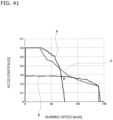
- the acceleration performance and high-speed performance can be improved by providing a transmission. More specifically, by providing a transmission, the relationship between the automobile's running speed and acceleration can be made smoother, similar to that of an automobile equipped with a gasoline engine and a transmission in the power transmission system. This point will be described with reference to FIG. 41 .
- JP H05-116549 A discloses a structure of an electric automobile drive device in which torque of an output shaft of an electric motor is increased by a two-speed transmission including a pair of planetary gear mechanisms and a pair of brakes, and then transmitted to a differential gear.
- this electric automobile drive device by switching between a connected state and a disconnected state of the pair of brakes, the components of the pair of planetary gear mechanisms are switched between a rotatable state and a non-rotatable state, making it possible to switch the reduction ratio between the output shaft of the electric motor and the differential gear between two stages of high and low.
- Patent Literature 1 JP H05-116549 A
- the torque transmitted to the brake can be calculated based on the relative rotational speed between the friction engagement elements, or in other words, the dependency of the friction coefficient with respect to the slip speed ( ⁇ -V characteristic), and the force pressing the friction engagement elements together.
- the friction coefficient between the friction engagement elements of the brake changes with changes in the usage environment and deterioration over time, and this causes the ⁇ -V characteristic to change as illustrated by the solid line to the dashed line in FIG. 42 . Therefore, when the ⁇ -V characteristic changes due to deterioration over time or due to changes in the external environment, it may become impossible to accurately estimate the torque transmitted to the brake when switching the reduction ratio, which may result in shift shock.
- an object according to the present disclosure is to achieve a structure capable of learning the ⁇ -V characteristic that changes with use in a two-speed transmission capable of switching the reduction ratio between two stages of high and low, and thereby making it possible to prevent the occurrence of shift shock regardless of changes in the usage environment or deterioration over time.
- An aspect of the present disclosure relates to a two-speed transmission.
- a two-speed transmission according to an aspect of the present disclosure includes a planetary transmission mechanism, an input member, an output member, a drive motor, a rotation transmission state switching device, and a friction engagement device.
- the planetary transmission mechanism includes an input element connected to the input member, an output element connected to the output member and capable of rotating relative to the input element, and a rotating element capable of rotating relative to the input element and the output element.
- the planetary transmission mechanism has a sun element, a ring element supported around the sun element so as to be capable of relative rotation with respect to the sun element, a carrier element supported so as to be capable of relative rotation with respect to the sun element and the ring element, and a plurality of planetary elements engaged with the sun element and the ring element so as to be capable of transmitting torque, the plurality of planetary elements rotatably supported by the carrier element.
- the input element is configured by one of the sun element, the ring element, and the carrier element.
- the output element is configured by one of the sun element, the ring element, and the carrier element, that is an element other than that of the input element.
- the rotating element is configured by a remaining element of the sun element, the ring element, and the carrier element, excluding those of the input element and the output element.
- the drive motor rotates and drives the input member directly or through a reducer.
- the rotation transmission state switching device is arranged between the rotating element and a fixed portion that does not rotate even during use, and switches between a free mode in which the rotating element is capable of rotating relative to the fixed portion and a locked mode in which the rotating element is not capable of rotating relative to the fixed portion.
- the friction engagement device has at least one first friction plate and at least one second friction plate supported to allow relative displacement in an axial direction, and is arranged between any two elements of the sun element, the ring element, and the carrier element, and switches to a connected mode in which the any two elements rotate integrally by pressing the first friction plate and the second friction plate against each other, and switches to a disconnected mode in which the any two elements rotate relative to each other by releasing a force pressing the first friction plate and the second friction plate against each other.
- the two-speed transmission includes a first mode in which the rotation transmission state switching device is in the free mode and the friction engagement device is in the connected mode, and a second mode in which the rotation transmission state switching device is in the locked mode and the friction engagement device is in the disconnected mode.
- the two-speed transmission includes a learning function that, by performing mode switching between the first mode and the second mode on a condition that a predetermined learning start condition is satisfied, and calculating a friction coefficient between the first friction plate and the second friction plate based on output torque of the drive motor and angular acceleration of an output shaft of the drive motor in an inertia phase during the mode switching, obtains a ⁇ -V characteristic that is a relationship between the friction coefficient and a differential rotation that is a difference in the rotational speed of the any two elements.
- rotational speed of the output shaft of the drive motor is kept constant, and after mode switching between the first mode and the second mode is started, it may be determined that the inertia phase has started on a condition that an amount of change per unit time of the differential rotation exceeds a predetermined threshold value.
- the two-speed transmission of an aspect of the present disclosure may include a control function that controls output torque of the drive motor and magnitude of the force pressing the first friction plate and the second friction plate against each other based on the ⁇ -V characteristic obtained by the learning function when switching between the first mode and the second mode.
- the friction engagement device may include an elastic biasing member, a cam device, and an electric actuator.
- the elastic biasing member elastically biases the first friction plate and the second friction plate in a direction so as to be pressed against each other.
- the cam device has a drive cam and a driven cam supported so as to be capable of rotating relative to the drive cam and capable of relative displacement in the axial direction.
- the cam device relatively displaces the driven cam in a direction that increases a distance in the axial direction between the drive cam and the driven cam, and thereby presses the elastic biasing member in a direction that releases the force pressing the first friction plate and the second friction plate against each other.
- the electric actuator has a shift motor and a shift reducer, and rotates and drives the drive cam by the shift motor through the shift reducer.
- the friction engagement device may include a return spring that elastically biases the first friction plate and the second friction plate in directions away from each other.
- the rotation transmission state switching device may have a one-way clutch mode in which rotation of the rotating element relative to the fixed portion is allowed only in a predetermined direction, and rotation of the rotating element relative to the fixed portion in a direction opposite to the predetermined direction is prevented.
- the two-speed transmission may include a function of setting the rotation transmission state switching device to the one-way clutch mode while the friction engagement device is being switched from the disconnected mode to the connected mode and/or while the friction engagement device is being switched from the connected mode to the disconnected mode.
- An aspect of the present disclosure relates to a method for learning a ⁇ -V characteristic, which, in the two-speed transmission, is the relationship between a friction coefficient between the first friction plate and the second friction plate and a differential rotation, which is the difference in rotational speed between the any two elements.
- the method for learning the ⁇ -V characteristic of the two-speed transmission by performing mode switching between the first mode and the second mode on a condition that a predetermined learning start condition is satisfied, and, in an inertia phase during the mode switching, calculating a friction coefficient based on output torque of the drive motor and angular acceleration of the output shaft of the drive motor, obtains the ⁇ -V characteristic.
- An aspect of the present disclosure relates to a transmission control method for the two-speed transmission.
- the transmission control method includes:
- the technique according to the present disclosure may be implemented by combining the above-described aspects as appropriate, provided that no contradiction occurs.
- the method for learning the ⁇ -V characteristic of the two-speed transmission and the transmission control method of the two-speed transmission according to an aspect of the present disclosure, it is possible to learn the ⁇ -V characteristic that changes with use, and therefore a two-speed transmission is provided that can prevent the occurrence of shift shock regardless of changes in the usage environment or deterioration over time.
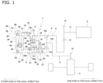
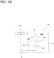
- the two-speed transmission 1 of the present example transmits output torque of the drive motor 2, which is a drive source, to a differential device 3 with increasing the output torque, that is, reducing rotational speed, or without increasing the output torque.
- each element of the two-speed transmission 1 and the differential device 3 is illustrated schematically in FIGS. 1 to FIG. 2B .
- the two-speed transmission 1 of the present example includes a drive motor 2, an input member 4, an output member 5, a friction engagement device 7, a rotation transmission state switching device 8, and a planetary transmission mechanism 9.
- the input member 4 is rotatably supported by a fixed portion 10, that is configured by a housing that accommodates the two-speed transmission 1 and does not rotate even during use, through a rolling bearing or the like (not illustrated).
- the input member 4 is configured to be cylindrical (hollow).
- the input member 4 also has an input gear 13 at an end portion on one side in the axial direction (the right side in FIG. 1 ) that engages with a drive gear 12 provided on an output shaft 11 of the drive motor 2.
- the output member 5 is supported coaxially with the input member 4 and supported so as to be capable of rotating relative to the input member 4.
- the output member 5 is supported at an inner side in the radial direction of the cylindrical input member 4 through a rolling bearing (not illustrated) or the like so as to be capable of rotating relative to the input member 4.
- the output member 5 has an output gear 14 at an end portion on the one side in the axial direction.
- the output gear 14 engages with a gear provided at an input portion of the differential device 3.
- the output member 5 rotates and drives the input portion of the differential device 3.
- the drive motor 2 rotates and drives the input member 4 thruogh a gear-type reducer consisting of a drive gear 12 and an input gear 13.
- the planetary transmission mechanism 9 includes an input element connected to the input member 4, an output element connected to the output member 5 and rotatable relative to the input element, and a rotating element rotatable relative to the input element and the output element.
- the planetary transmission mechanism 9 has a sun element, a ring element supported around the sun element so as to be capable of relative rotation with respect to the sun element, a carrier element supported so as to be capable of relative rotation with respect to the sun element and the ring element, and a plurality of planetary elements engaged with the sun element and the ring element so as to be capable of transmitting torque and rotatably supported by the carrier element.
- the input element is configured by any one of the sun element, the ring element, and the carrier element.
- the output element is configured by any one of the sun element, the ring element, and the carrier element, that is different from the input element.
- the rotating element is configured by the remaining elements of the sun element, the ring element, and the carrier element, excluding the input element and the output element.
- the planetary transmission mechanism 9 is configured by a planetary gear mechanism in which gears engage with each other. That is, the sun element is configured by a sun gear 101, the ring element is configured by a ring gear 102, the carrier element is configured by a carrier 103, and the plurality of planetary elements are configured by a plurality of planetary gears 104. Therefore, the planetary transmission mechanism 9 is configured by a single-pinion type planetary gear mechanism in which each of the plurality of planetary gears 104 engages with both the sun gear 101 and the ring gear 102.
- a double-pinion type planetary gear mechanism may also be adopted as a planetary reduction mechanism.
- the planetary transmission mechanism may be configured by a planetary roller mechanism.
- the sun element is configured by a sun roller
- the ring element is configured by a ring roller
- the plurality of planetary elements are configured by a plurality of planetary rollers.
- the sun gear 101 is provided at an end portion on the one side in the axial direction of the rotating member 6.
- the rotating member 6 is supported coaxially with the input member 4 and the output member 5 and supported so as to be capable of rotating relative to the input member 4 and the output member 5. More specifically, the rotating member 6 is rotatably supported by the fixed portion 10 through the rotation transmission state switching device 8, a cam device 28 of the friction engagement device 7, and a radial bearing 38 for rotatably supporting the drive cam 34 of the cam device 28 with respect to the rotating member 6.
- the rotating member 6 has a small diameter flange portion 15 that protrudes outward in the radial direction at an intermediate portion in the axial direction, and also has a flange portion 16 that protrudes outward in the radial direction at a portion located farther on the other side in the axial direction (the left side in FIG. 1 ) than the small diameter flange portion 15.
- the flange portion 16 has a first circular ring portion 18 in the form of a hollow circular plate, a first cylindrical portion 19 bent from an end portion on an outer side in the radial direction of the first circular ring portion 18 toward the other side in the axial direction, a second circular ring portion 20 in the form of a hollow circular plate bent from an end portion on the other side in the axial direction of the first cylindrical portion 19 toward the outer side in the radial direction, and a second cylindrical portion 21 bent from an end portion on the outer side in the radial direction of the second circular ring portion 20 toward the other side in the axial direction.
- the first circular ring portion 18 has partially arc-shaped through holes 17 at a plurality of positions in an intermediate portion in the radial direction thereof for inserting partial cylindrical portions 63 of the pressing members 58 of the friction engagement device 7 therethrough.
- the rotating member 6 is configured by externally fitting and fixing a stepped cylindrical member 23, as illustrated on the left side of FIG. 13B , to a shaft member 22 having a small diameter flange portion 15. That is, the stepped cylindrical member 23 has a flange portion 16 and a small diameter cylindrical portion 24 bent from an end portion on an inner side in the radial direction of the first circular ring portion 18 of the flange portion 16 toward the other side in the axial direction.
- the stepped cylindrical member 23 is supported and fixed by the shaft member 22 by, for example, bring a female spline portion 25 provided on the inner circumferential surface of the small diameter cylindrical portion 24 and a male spline portion provided on the outer circumferential surface of the shaft member 22 into a spline engagement.
- the rotating member may also be configured by joining and fixing the stepped cylindrical member and the shaft member by press fitting, welding, or the like.
- the rotating element is configured by the sun gear 101.
- the ring gear 102 is arranged around the sun gear 101 and coaxially with the sun gear 101, and is connected to the input member 4 so as to be capable of transmitting torque.
- the ring gear 102 is provided at an intermediate portion in the axial direction of the input member 4.
- the input element is configured by the ring gear 102.
- the carrier 103 is arranged between the sun gear 101 and the ring gear 102 in the radial direction and coaxially with the sun gear 101 and the ring gear 102, and is connected to the output member 5 so as to be capable of transmitting torque.
- the output element is configured by the carrier 103.
- the plurality of planetary gears 104 engage with the sun gear 101 and the ring gear 102.
- Each of the plurality of planetary gears 104 is supported by the carrier 103 so as to be capable of rotation (spinning) about its own central axis.
- the rotation transmission state switching device 8 is arranged between the rotating element (in the present example, the sun gear 101) and the fixed portion 10 that does not rotate even during use, and switches between the free mode in which the sun gear 101 as the rotating element can rotate relative to the fixed portion 10, and a locked mode in which the sun gear 101 cannot rotate.
- the rotation transmission state switching device 8 includes a first member 71 and a second member 72 arranged coaxially with each other, and a mode selection member 73 that rotates in conjunction with the rotation of the drive cam 34.
- the first member 71 is connected to the sun gear 101 so as to be capable of transmitting torque, and the second member 72 is supported by and fixed to the fixed portion 10.
- the rotation transmission state switching device 8 in the present example has a free mode in which rotation of the first member 71 relative to the fixed portion 10 is allowed regardless of the rotation direction of the first member 71, a locked mode in which rotation of the first member 71 relative to the fixed portion 10 is prevented regardless of the rotation direction of the first member 71, and a one-way clutch mode in which rotation of the first member 71 is only allowed in a predetermined direction. More specifically, the rotation transmission state switching device 8 of the present example switches among the free mode, the locked mode, and the one-way clutch mode based on the rotation of the mode selection member 73.
- the first member 71 has on the outer circumferential surface thereof, a gear-shaped uneven portion 76 in which engaging recessed portions 74 and protruding portions 75 are alternately arranged in the circumferential direction.
- the first member 71 has an outer diameter side uneven engaging portion 77 on the inner circumferential surface thereof, with recessed portions and protruding portions being arranged alternately in the circumferential direction.
- the first member 71 is supported so as not to rotate relative to the rotating member 6 by engaging the outer diameter side uneven engaging portion 77 with an inner diameter side uneven engaging portion 78 provided on the outer circumferential surface of the second cylindrical portion 21 of the rotating member 6, and rotates integrally with the rotating member 6 and the sun gear 101.
- the second member 72 is supported around the first member 71 and coaxially with the first member 71 and is capable of relative rotation with respect to the first member 71.
- the inner circumferential surface of the second member 72 faces the tip-end surfaces of the protruding portions 75 of the first member 71 with a gap therebetween.
- the second member 72 has an inner diameter side uneven engaging portion 79 on the outer circumferential surface thereof, with recessed portions and protruding portions being arranged alternately in the circumferential direction.
- the second member 72 is supported so as not to rotate relative to the fixed portion 10 by engaging the inner diameter side uneven engaging portion 79 with the outer diameter side uneven engaging portion provided on the inner circumferential surface of the fixed portion 10.
- the second member 72 includes a base portion 80 having a rectangular cross-sectional shape, and a cylindrical portion 81 that protrudes from an end portion on the outer side in the radial direction of a surface on the one side in the axial direction of the base portion 80 over the entire circumference towards the one side in the axial direction.
- the base portion 80 has a plurality of first retaining recessed portions 82 and a plurality of second retaining recessed portions 83 (six each in the illustrated example) that are alternately arranged in the circumferential direction.
- Each of the first retaining recessed portions 82 opens to the inner circumferential surface and a surface on the other side in the axial direction of the base portion 80.
- Each first retaining recessed portion 82 includes a spring retaining portion 84a and a pedestal portion 85a.
- the spring retaining portion 84a has a roughly rectangular opening shape with a long axis thereof extending outward in the radial direction as approaching the one side in the circumferential direction (the front clockwise side in FIGS. 17 to 19 ) when viewed from the other side in the axial direction.
- the pedestal portion 85a has a generally circular opening shape when viewed from the other side in the axial direction, and is arranged adjacent to the other side in the circumferential direction of the spring retaining portion 84a (the rear side in the clockwise direction in FIGS. 17 to 19 ).
- Each of the second retaining recessed portions 83 opens to the inner circumferential surface and the other side surface in the axial direction of the base portion 80, and includes a spring retaining portion 84b and a pedestal portion 85b.
- the second retaining recessed portion 83 has a shape symmetrical to the first retaining recessed portion 82 with respect to an imaginary plane including the central axis of the second member 72.
- the rotation transmission state switching device 8 has a first claw member 86, a second claw member 87, a first claw biasing member 88, and a second claw biasing member 89 between the first member 71 and the second member 72.
- the number of first claw members 86, second claw members 87, first claw biasing members 88, and second claw biasing members 89 are plural and equal.
- Each of the first claw members 86 includes a first base portion 90 and a first engagement claw 91.
- the first base portion 90 is configured in a substantially cylindrical shape and is supported (pivoted) on the pedestal portion 85a of the first retaining recessed portion 82 so as to be able to pivot about a pivot axis parallel to the central axis of the second member 72.
- the first engagement claw 91 is formed in a substantially flat plate shape and extends from the first base portion 90 towards one side in the circumferential direction.
- a portion on the other side in the axial direction is made to face (engage with) the outer circumferential surface of an annular protruding portion 92 of the mode selection member 73, and a portion on the one side in the axial direction is made to face an uneven portion 76 of the first member 71 (engages with the engagement recess 74 so as to be able to engage and disengage).
- Each second claw member 87 includes a second base portion 93 supported to be pivotable on the pedestal portion 85b of the second retaining recessed portion 83, and a second engagement claw 94 extending from the second base portion 93 toward the other side in the circumferential direction.
- the second claw member 87 When viewed from the other side in the axial direction, the second claw member 87 has a shape symmetrical to the first engagement claw 91 with respect to an imaginary plane including the central axis of the second member 72, and is arranged symmetrical to the first engagement claw 91.
- the first claw biasing member 88 elastically biases the first engagement claw 91 of the first claw member 86 in a direction to engage with an engaging recessed portion 74 of the first member 71. That is, the first claw biasing member 88 applies a biasing force to the first claw member 86 in a direction that causes the first claw member 86 to pivot in the clockwise direction in FIG. 18 around the central axis (pivot) of the first base portion 90.
- the first claw biasing member 88 is configured by an elastic member such as a coil spring, and is held in an elastically compressed state between a bottom surface (surface facing inward in the radial direction) of the spring retaining portion 84a of the first retaining recessed portion 82 and the outer side surface in the radial direction of the first engagement claw 91.
- the second claw biasing member 89 is configured by an elastic member similar to the first claw biasing member 88, and is arranged symmetrically to the first claw biasing member 88 with respect to an imaginary plane including the central axis of the second member 72 when viewed from the other side in the axial direction. That is, the second claw biasing member 89 is held in an elastically compressed state between a bottom surface of the spring retaining portion 84b of the second retaining recessed portion 83 and an outer side surface in the radial direction of the second engagement claw 94, and elastically biases the second engagement claw 94 of the second claw member 87 in a direction to engage with the engaging recessed portion 74 of the first member 71.
- the mode selection member 73 includes a substantially circular plate-shaped base portion 95 and an annular protruding portion 92 that protrudes from an intermediate portion in the radial direction of a surface on the other side in the axial direction of the base portion 95 toward the other side in the axial direction over the entire circumference.
- the base portion 95 has plate side engagement holes 96 at a plurality of locations (three locations in the illustrated example) at equal intervals in the circumferential direction of an intermediate portion in the radial direction of the surface on the other side in the axial direction. End portions on the one side in the axial direction of pin portions 50 are respectively fitted (engaged) into the plate-side engagement holes 96 without any looseness. That is, the mode selection member 73 rotates integrally with (in the same direction and at the same speed as) the drive cam 34.
- the annular protruding portion 92 has protrusions 97 that protrude outward in the radial direction at a plurality of locations in the circumferential direction on the outer circumferential surface. That is, the annular protruding portion 92 has a gear-shaped uneven portion 98 in which protrusions 97 and recessed portions are alternately arranged in the circumferential direction on the outer circumferential surface.
- the first member 71, the second member 72, and the mode selection member 73 are combined by a cover body 99 and a retaining ring 100 so as to be capable of relative rotation but not capable of relative displacement in the axial direction (so as to prevent inadvertent separation in the axial direction), thereby forming the rotation transmission state switching device 8.
- a circular ring-shaped cover body 99 is supported by and fixed to a surface on the one side in the axial direction of the second member 72 by screwing, and a surface on the other side in the axial direction of the inner portion in the radial direction of the cover body 99 faces the surface on the one side in the axial direction of the first member 71. This prevents the first member 71 from displacing toward the one side in the axial direction with respect to the second member 72.
- the retaining ring 100 is engaged with the end portion on the other side in the axial direction of the inner circumferential surface of the cylindrical portion 81 of the second member 72. This prevents the first member 71 and the mode selection member 73 from displacing toward the other side in the axial direction with respect to the second member 72.
- the rotation transmission state switching device 8 is configured to be able to switch between the free mode, the locked mode, and the one-way clutch mode by switching the engagement state between the first engagement claw 91 of the first claw member 86 and the engaging recessed portion 74 of the first member 71, and the engagement state between the second engagement claw 94 of the second claw member 87 and the engaging recessed portion 74 based on the rotation of the mode selection member 73.
- the phase in the circumferential direction of the mode selection member 73 relative to the second member 72 is adjusted, and as illustrated in FIG. 19A , the protrusion 97 pushes the first engagement claw 91 outward in the radial direction against the elastic force of the first claw biasing member 88, and pushes the second engagement claw 94 outward in the radial direction against the elastic force of the second claw biasing member 89.
- the engaging recessed portions 74 of the first member 71 are disengaged from the first engagement claw 91 and the second engagement claw 94.
- the first member 71 is allowed to rotate relative to the second member 72. In other words, regardless of the rotation direction of the first member 71, rotation of the first member 71 relative to the fixed portion 10 is allowed.
- the phase in the circumferential direction of the mode selection member 73 with respect to the second member 72 is adjusted, and as illustrated in FIG. 19B , the protrusions 97 are positioned at portions offset in the circumferential direction from the first engagement claw 91 of the first claw member 86 and the second engagement claw 94 of the second claw member 87. That is, in the circumferential direction, the recessed portions of the uneven portion 98 are aligned in phase with the first engagement claws 91 and the second engagement claws 94.
- the engaging recessed portions 74 of the first member 71 engage with the first engagement claws 91 and the second engagement claws 94.
- the first member 71 is prevented from rotating relative to the second member 72. That is, regardless of the direction of rotation of the first member 71, rotation of the first member 71 relative to the fixed portion 10 is prevented.
- the phase in the circumferential direction of the mode selection member 73 relative to the second member 72 is adjusted, and as illustrated in FIG. 19C , the protrusion 97 pushes only the second engagement claw 94 outward in the radial direction against the elastic force of the second claw biasing member 89.
- the rotation transmission state switching device 8 operates as a ratchet-type one-way clutch.
- the predetermined direction coincides with the forward rotation direction of the input member 4.
- the normal rotation direction of the input member 4 refers to the rotation direction of the input member 4 when moving the automobile forward.
- the friction engagement device 7 has at least one first friction plate 30 and at least one second friction plate 31 supported so as to be capable of relative displacement in the axial direction, and is arranged between any two elements of the sun element (sun gear 101), the ring element (ring gear 102), and the carrier element (carrier 103), and by pressing the first friction plate 30 and the second friction plate 31 against each other, switches to the connected mode in which the any two elements rotate together, and by releasing the force pressing the first friction plate 30 and the second friction plate 31 against each other, switches to the disconnected mode in which the any two elements rotate relative to each other.
- the friction engagement device 7 is provided between the sun gear 101 and the ring gear 102, and in the connected mode, the sun gear 101 and the ring gear 102 rotate together, and in the disconnected mode, the sun gear 101 and the ring gear 102 rotate relative to each other.
- torque is transmitted between the input member 4 and the rotating member 6, and in the disconnected mode, torque is not transmitted between the input member 4 and the rotating member 6.
- the friction engagement device 7 includes a friction engagement portion 26, an elastic biasing member 27, a cam device 28, and an electric actuator 29.
- the friction engagement portion 26 is configured by a multi-plate clutch in which a plurality of first friction plates 30 supported by the rotating member 6 and a plurality of second friction plates 31 supported by the input member 4 are alternately stacked.
- the plurality of first friction plates 30 are supported on the outer circumferential surface of the first cylindrical portion 19 so as to be capable of displacement in the axial direction, and so as not to be capable of relative rotation with respect to the first cylindrical portion 19.
- the plurality of second friction plates 31 are supported on the inner circumferential surface of an end portion on the other side in the axial direction of the input member 4 so as to be capable of displacement in the axial direction and so as not to be capable of relative rotation with respect to the input member 4.
- the elastic biasing member 27 is provided between the rotating member 6 and the frictional engagement portion 26, and elastically biases the first friction plate 30 and the second friction plate 31 in a direction in which they are pressed against each other.
- the elastic biasing member 27 has a piston 32 and an elastic member 33.
- the piston 32 is supported so as to be capable of displacement in the axial direction relative to the rotating member 6.
- the piston 32 is configured as a hollow circular plate, and is supported around a portion of the rotating member 6 between the small diameter flange portion 15 and the flange portion 16 in the axial direction so as to be capable of displacement in the axial direction relative to the rotating member 6.
- an end surface on the other side in the axial direction of a portion on the outer side in the radial direction faces a surface on the one side in the axial direction of the first friction plate 30 or the second friction plate 31 that is located the farthest on the one side in the axial direction of the first friction plate 30 or the second friction plate 31.
- the elastic member 33 is provided between the rotating member 6 and the piston 32.
- the elastic member 33 is sandwiched in an elastically compressed state between the surface on the other side in the axial direction of the small diameter flange portion 15 of the rotating member 6 and the surface on the one side in the axial direction of the piston 32.
- the elastic biasing member 27 elastically biases the first friction plate 30 and the second friction plate 31 in directions pressing against each other.
- the elastic member 33 is composed of at least one disc spring (two disc springs in the present example).
- the specific configuration of the elastic member is not particularly limited.
- the elastic member may be configured by at least one coil spring.
- the cam device 28 has a drive cam 34 and a driven cam 35 supported so as to be capable of relative rotation with respect to the drive cam 34 and capable of relative displacement in the axial direction.
- the cam device 28 relatively displaces the driven cam 35 in a direction that increases a distance in the axial direction between the drive cam 34 and the driven cam 35, and thereby presses the elastic biasing member 27 in a direction that releases the force pressing the first friction plate 30 and the second friction plate 31 against each other.
- the drive cam 34 is supported by the rotating member 6 so as to be capable of rotating relative to the rotating member 6 and the input member 4 and so as not to be capable of displacement in the axial direction relative to the rotating member 6. More specifically, as illustrated in FIG. 4 and other figures, the drive cam 34 is supported by the rotating member 6 through a tubular member 37, a radial bearing 38, and an angular ball bearing 39 so as to be capable of rotating relative to the rotating member 6.
- the tubular member 37 has a cylindrical portion 40 and an outward-facing flange portion 41 bent outward in the radial direction from an end portion on the other side in the axial direction of the cylindrical portion 40.
- the outward-facing flange portion 41 of the tubular member 37 is supported by and fixed to the fixed portion 10 by screwing or the like.
- the radial bearing 38 has an inner ring 42 externally fitted and fixed to an end portion on the other side in the axial direction of the rotating member 6, an outer ring 43 internally fitted and fixed to the cylindrical portion 40 of the tubular member 37, and a plurality of rolling elements 44 arranged between the inner ring 42 and the outer ring 43 so as to be able freely roll.
- the radial bearing 38 is configured as a double-row deep groove ball bearing that uses balls as the rolling elements 44.
- the radial bearing is not particularly limited as long as the radial bearing can support radial and axial loads, and could be, for example, a deep groove ball bearing, a radial angular contact ball bearing, or a radial tapered roller bearing.
- the angular ball bearing 39 has an inner ring 45 externally fitted and fixed to the cylindrical portion 40 of the tubular member 37, an outer ring 46 internally fitted and fixed to the drive cam 34, and a plurality of balls 47 arranged between the inner ring 45 and the outer ring 46 so as to be able to freely roll.
- the drive cam 34 has wheel teeth 49 as a helical gear on the outer circumferential surface, and also has pin portions 50 that protrude toward the one side in the axial direction at a plurality of locations in the circumferential direction (three locations in the illustrated example) of an intermediate portion in the radial direction of a surface on the one side in the axial direction.
- the driven cam 35 is arranged around the rotating member 6 so as to be capable of displacement only in the axial direction.
- the driven cam 35 has a hollow circular plate shape, and is supported by the fixed portion 10 so as to be capable of displacement in the axial direction.
- a female spline portion 51 provided on the inner circumferential surface of the driven cam 35 is engaged using a spline engagement with a male spline portion 52 provided on the outer circumferential surface of a portion on the one side in the axial direction of the cylindrical portion 40 of the tubular member 37, thereby supporting the driven cam 35 by the fixed portion 10 so as to be capable of displacement in the axial direction.
- the method of supporting the driven cam by the fixed portion is not particularly limited as long as the driven cam can be supported by the fixed portion so as to be capable of only displacement in the axial direction.
- the driven cam can be supported by the fixed portion so as to be capable of displacement in the axial direction by a key engagement between a protruding portion on one of the driven cam and the fixed portion with a recessed groove in the other.
- the driven cam 35 has rectangular holes 53 penetrating in the axial direction at a plurality of locations (three locations in the illustrated example) in the circumferential direction of an intermediate portion in the radial direction, and has support plate portions 54a, 54b having an approximately semicircular plate shape protruding toward the other side in the axial direction from portions on both sides in the radial direction of each of the rectangular holes 53.
- the support plate portion 54a on the outer side in the radial direction has a support hole 55 that is a circular hole that penetrates in the radial direction
- the support plate portion 54b on the inner side in the radial direction has a support recessed portion 56 with a circular opening on the surface on the outer side in the radial direction.
- the driven cam 35 faces the piston 32 of the elastic biasing member 27 through a thrust bearing 57 and a pressing member 58.
- the thrust bearing 57 is provided between the pressing member 58 and the driven cam 35.
- the thrust bearing 57 has a pair of raceways 59a, 59b and a plurality of rolling elements 60 arranged to roll freely between the pair of raceways 59a, 59b.
- the raceway 59b on the other side in the axial direction is supported by and fixed to the driven cam 35.
- the pressing member 58 has a cylindrical base portion 62 and partial cylindrical portions 63 that protrude toward the one side in the axial direction from a plurality of locations in the circumferential direction (three locations in the illustrated example) of an end portion on the one side in the axial direction of the base portion 62.
- the raceway 59a on the one side in the axial direction is supported by and fixed to an end portion on the other side in the axial direction of the base portion 62.
- the partial cylindrical portions 63 are respectively inserted into the through holes 17 of the rotating member 6, and the tip-end portions (end portions on the one side in the axial direction) of the partial cylindrical portions 63 face an intermediate portion in the radial direction of a surface on the other side in the axial direction of the piston 32.
- a preload applying means 61 for applying a preload to the thrust bearing 57 is provided between the pressing member 58 and the rotating member 6.
- the preload applying means 61 is sandwiched in an elastically compressed state between the pressing member 58 and a surface on the other side in the axial direction of the first circular ring portion 18 of the flange portion 16 of the rotating member 6.
- the preload applying means 61 can be configured by, for example, at least one disc spring or at least one coil spring. In the present example, the preload applying means 61 is configured by one coil spring.
- the cam device 28 has a plurality of rolling elements 36 (three in the present example) and a drive cam surface 48 provided on the drive cam 34 as a means for relatively displacing the drive cam 34 and the driven cam 35.
- the drive cam surface 48 is formed by arranging an equal number of recessed portions and protruding portions alternately in the circumferential direction on an inner side portion in the radial direction of a surface on the one side in the axial direction of the drive cam 34.
- the drive cam surface 48 is configured by arranging a first bottom portion 48a, a first inclined surface portion 48b, a first flat surface portion 48c, a second inclined surface portion 48d, a second bottom portion 48e, a third inclined surface portion 48f, a second flat surface portion 48g, and a fourth inclined surface portion 48h in this order, with the number of times being repeated corresponding to the number of rolling elements 36 (three times in the present example).
- the first flat surface portion 48c and the second flat surface portion 48g are located the farthest on the one side in the axial direction, that is, are located at the tip-end portion of protruding portions, and the first bottom portion 48a and the second bottom portion 48e are located the farthest on the other side in the axial direction.
- the inclination angles of the third inclined surface portion 48f and the fourth inclined surface portion 48h with respect to an imaginary plane P perpendicular to the central axis of the drive cam 34 are larger than the inclination angle of the first inclined surface portion 48b with respect to the imaginary plane P.
- the inclination angle of the first inclined surface portion 48b and the inclination angles of the third inclined surface portion 48f and the fourth inclined surface portion 48h are all set to a magnitude that allows the rolling elements 36 to move either in a rolling down manner or in rolling up manner.
- the third inclined surface portion 48f and the fourth inclined surface portion 48h are inclined in opposite directions from each other and have the same inclination angle as each other.
- the inclination angles of the third inclined surface portion 48f and the fourth inclined surface portion 48h may be different from each other.
- the inclination angle of the first inclined surface portion 48b and the inclination angles of the third inclined surface portion 48f and the fourth inclined surface portion 48h may be the same as each other.
- the inclination angle of the second inclined surface portion 48d with respect to the imaginary plane P may be set to any value as long as the rolling elements 36 can ride up thereon.
- Each of the rolling elements 36 has a cylindrical shape and is supported by a columnar support shaft 64 and a plurality of rollers 65 so as to be able to freely rotate about its own axis relative to the support plate portions 54a, 54b. That is, an end portion on the outer side in the radial direction of the support shaft 64 centered on the central axis of the driven cam 35 is internally fitted and fixed into the support hole 55 of the support plate portion 54a on the outer side in the radial direction, and an end portion on the inner side in the radial direction of the support shaft 64 centered on the central axis of the driven cam 35 is internally fitted and fixed into the support recess 56 of the support plate portion 54b on the inner side in the radial direction.
- the plurality of rollers 65 are sandwiched between the inner circumferential surface of the rolling element 36 and the outer circumferential surface of an intermediate portion in the axial direction of the support shaft 64 so as to be able to freely roll.
- the rolling element 36 is supported by the driven cam 35 so as to be freely rotatable (rotating) about a rotation axis C that faces in a radial direction centered on the central axis of the driven cam 35.
- the drive cam 34 is rotationally driven to increase or decrease the amount that the rolling element 36 rides up from the first bottom portion 48a or the second bottom portion 48e of the drive cam surface 48, thereby moving the driven cam 35 in the axial direction and switching the friction engagement portion 26 between the connected state and the disconnected state.
- the rolling element 36 is positioned on the first flat surface portion 48c or the second flat surface portion 48g of the drive cam surface 48, or the amount that the rolling elements 36 rides up onto the first inclined surface portion 48b, the second inclined surface portion 48d, the third inclined surface portion 48f, or the fourth inclined surface portion 48h is increased.
- the piston 32 of the elastic biasing member 27 is pressed toward the one side in the axial direction through the thrust bearing 57 and the pressing member 58, and the elastic member 33 is elastically compressed. This reduces the force pressing the first friction plate 30 and the second friction plate 31 against each other, and ultimately causes the force to be lost. In this manner, the friction engagement portion 26 is disconnected, and the friction engagement device 7 is switched to the disconnected mode.
- the rolling element 36 is positioned at the first bottom portion 48a or the second bottom portion 48e of the drive cam surface 48, or the amount that the rolling elements 36 rides up onto the first inclined surface portion 48b, the second inclined surface portion 48d, the third inclined surface portion 48f, or the fourth inclined surface portion 48h is reduced.
- the driven cam 35 can be reliably displaced in the axial direction based on the rotation of the drive cam 34, and switching the mode of the two-speed transmission 1 can be performed with high precision.
- the driven cam may not be able to displace in the axial direction, or the amount of displacement in the axial direction of the driven cam relative to the amount of rotation of the drive cam may not be sufficiently secured.
- rollers are used as the rolling elements 36, and the rolling elements 36 are supported so as to be able to freely rotate (spin) around a rotation axis C facing in the radial direction centered on the central axis of the driven cam 35. Therefore, it is possible to prevent slippage from occurring at the area of rolling contact between the outer circumferential surface of the rolling element 36 and the drive cam surface 48, and due to the rotation of the drive cam 34, the driven cam 35 can be reliably displaced in the axial direction. As a result, switching the mode of the two-speed transmission 1 can be performed with high accuracy.
- balls may also be used as the rolling elements of the cam device.
- the cam device 28 is configured by sandwiching the rolling elements 36 between the drive cam 34 and the driven cam 35; however, in a case of implementing the technique according to the present disclosure, the cam device is not particularly limited as long as the cam device can press the elastic biasing member in the direction to release the force pressing the first friction plate and the second friction plate against each other, and any other known means may also be applied.
- the cam device may have a structure in which the rolling elements are arranged between the drive cam surface of the drive cam and the driven cam surface of the driven cam, a structure in which the drive cam surface of the drive cam and the driven cam surface of the driven cam are directly engaged (sliding) with each other, or a structure in which the driven cam has a guide groove that extends in the circumferential direction on the outer circumferential surface thereof and changes in the axial direction, and the drive cam has an engaging protruding portion that engages with the guide groove to enable displacement along the guide groove.
- the electric actuator 29 has a shift motor 66 and a reducer 67, and the drive cam 34 is rotated and driven by the shift motor 66 through the reducer 67.
- the reducer 67 is configured by a worm reducer. That is, the reducer 67 is configured by worm teeth provided on the outer circumferential surface of a worm 68 connected to an output shaft of the shift motor 66 engaging with wheel teeth 49 provided on the outer circumferential surface of the drive cam 34.
- the worm 68 is rotatably supported by the fixed portion 10 by a pair of support bearings 69a, 69b.
- the reducer 67 may also be configured by engaging a spur gear or a bevel gear provided on an output shaft of an electric motor with a spur gear or bevel gear provided on the drive cam, or by passing a belt or chain between an output shaft of an electric motor and the drive cam.
- a return spring 70 is further provided between the first friction plate 30 and the second friction plate 31, and elastically biases the first friction plate 30 and the second friction plate 31 in directions to increase the gap between them.
- the elastic force of the return spring 70 is smaller than the elastic restoring force of the elastic member 33 of the elastic biasing member 27.
- the two-speed transmission 1 of the present example has a first mode in which the rotation transmission state switching device 8 is in the free mode and the friction engagement device 7 is in the connected mode, and a second mode in which the rotation transmission state switching device 8 is in the locked mode and the friction engagement device 7 is in the disconnected mode.
- the planetary transmission mechanism 9 enters a glued state in which the entire mechanism rotates as one unit. In this state, the torque input to the input member 4 is transmitted to the output member 5 as is without being increased.
- the two-speed transmission 1 when the two-speed transmission 1 is switched to the second mode by setting the rotation transmission state switching device 8 to the locked mode and the friction engagement device 7 to the disconnected mode, the torque input to the input member 4 is increased by the planetary transmission mechanism 9 and then transmitted to the output member 5. That is, in the two-speed transmission 1 of the present example, the first mode corresponds to a low reduction ratio mode in which the reduction ratio between the input member 4 and the output member 5 is small, and the second mode corresponds to a high reduction ratio mode in which the reduction ratio is larger than that in the low reduction ratio mode.
- the two-speed transmission 1 of the present example passes through a reduction ratio switching mode during switching from the high reduction ratio mode (second mode) to the low reduction ratio mode (first mode). Furthermore, the two-speed transmission 1 of the present example can be switched to a neutral mode in which no torque is transmitted between the input member 4 and the output member 5, and a parking mode in which the rotation of the output member 5 is locked.
- the friction engagement device 7 is switched to the connected mode, and the rotation transmission state switching device 8 is switched to the free mode.
- the rolling element 36 is positioned at the first bottom portion 48a of the drive cam surface 48, and the driven cam 35 is displaced in a direction in which the distance in the axial direction between the driven cam 35 and the drive cam 34 is reduced (toward the other side in the axial direction).
- the force of the elastic biasing member 27 pressing the piston 32 toward the one side in the axial direction is lost.
- the piston 32, thrust bearing 57 and pressing member 58 are pressed toward the other side in the axial direction mainly by the elastic restoring force of the first friction plate 30 and the elastic member 33, and the piston 32 presses the first friction plate 30 or the second friction plate 31 that closest to the one side in the axial direction toward the other side in the axial direction.
- the phase in the circumferential direction of the mode selection member 73 relative to the second member 72 is adjusted at the same time, and due to this, as illustrated in FIG. 19A , the protrusion 97 pushes up the first engagement claw 91 outward in the radial direction, and also pushes up the second engagement claw 94 outward in the radial direction.
- the engaging recessed portion 74 of the first member 71 disengages from the first engagement claw 91 and the second engagement claw 94, and the rotation transmission state switching device 8 switches to the free mode in which rotation of the first member 71 relative to the second member 72 is allowed regardless of the relative rotational direction between the first member 71 and the second member 72.
- the rotating member 6 is allowed to rotate relative to the fixed portion 10, and the sun gear 101 is allowed to rotate.
- the sun gear 101, the ring gear 102, and the carrier 103 rotate in the same direction and at the same speed, and the entire planetary transmission mechanism 9 rotates as a unit, in a glued state. Therefore, the rotational torque of the input member 4 is transmitted in the order of the input member 4, the carrier 103, and the output member 5, as indicated by the thick line in FIG. 2A , and is extracted from the output member 5.
- the friction engagement device 7 is switched to the disconnected mode, and the rotation transmission state switching device 8 is switched to the locked mode.
- the rolling element 36 is positioned on the first flat surface portion 48c of the drive cam surface 48, and the driven cam 35 is displaced in a direction (toward the one side in the axial direction) in which the distance in the axial direction between the driven cam 35 and the drive cam 34 increases.
- the piston 32 of the elastic biasing member 27 being pressed toward the one side in the axial direction through the thrust bearing 57 and the pressing member 58, the elastic member 33 is elastically compressed, and the force pressing the first friction plate 30 and the second friction plate 31 against each other is lost.
- the phase in the circumferential direction of the mode selection member 73 relative to the second member 72 is adjusted at the same time, and due to this, the protrusion 97 is positioned at a portion offset in the circumferential direction from the first engagement claw 91 and the second engagement claw 94, as illustrated in FIG. 19B .
- the engaging recessed portions 74 of the first member 71 engage with the first engagement claw 91 and the second engagement claw 94, and the rotation transmission state switching device 8 switches to the locked mode in which rotation of the first member 71 relative to the second member 72 is prevented regardless of the relative rotation direction between the first member 71 and the second member 72.
- rotation of the rotating member 6 relative to the fixed portion 10 is prevented, and rotation of the sun gear 101 is prevented.
- the rotational torque of the input member 4 is transmitted as illustrated by the thick line in FIG. 2B in the order of the input member 4, the ring gear 102, the rotational motion of the planetary gear 104, the orbital motion of the planetary gear 104 based on engagement with the sun gear 101 and the carrier 103, and the output member 5, and is then extracted from the output member 5.
- the reduction ratio between the input member 4 and the output member 5 is determined by the gear ratio between the ring gear 102 and the sun gear 101 (number of teeth of the ring gear 102/number of teeth of the sun gear 101).
- the reduction ratio between the input member 4 and the output member 5 can be switched between two stages of high and low, by switching the mode of the friction engagement device 7 and the mode of the rotation transmission state switching device 8 based on the rotational drive of one drive cam 34 by one electric actuator 29.
- the two-speed transmission 1 when the power input to the input member 4 is in a low-speed and high-torque region, the two-speed transmission 1 is switched to the high reduction ratio mode, and when the power input to the input member 4 is in a high-speed and low-torque region, the two-speed transmission 1 is switched to a low reduction ratio mode.
- the acceleration and high-speed performance of an electric automobile or hybrid automobile running using only an electric motor as a drive source can be made to have characteristics that are a continuation of the portion of the solid line on the left side of point P and the portion of the chain line b on the right side of P in FIG. 41 , and can be made to be similar to those of a gasoline engine automobile illustrated by the dashed line c in FIG. 41 .
- the mode of the friction engagement device 7 and the mode of the rotation transmission state switching device 8 are switched by the electric actuator 29 driving and rotating one drive cam 34. That is, in the two-speed transmission 1 of the present example, there is no need for a hydraulic system to control friction engagement devices such as clutches and brakes. This allows the system in electric automobiles and hybrid automobiles to be simplified, reducing costs and improving electricity consumption performance.
- the mode switching of the friction engagement device and the mode switching of the rotation transmission state switching device can be performed by separate actuators.
- the output torque and rotational speed R s of the drive motor 2 and the rotational speed of the shift motor 66 are controlled, and the two-speed transmission 1 is switched to the reduction ratio switching mode.
- the two-speed transmission 1 is switched to the reduction ratio switching mode.
- the protrusion 97 pushes only the second engagement claw 94 outward in the radial direction against the elastic force of the second claw biasing member 89, as illustrated in FIG. 19C .
- the rotation transmission state switching device 8 switches to the one-way clutch mode which allows only rotation of the first member 71 relative to the second member 72 in the predetermined direction (the predetermined direction in FIG. 19C ) and prevents rotation in the direction opposite to the predetermined direction.
- the friction engagement device 7 starts to switch from the disconnected mode to the connected mode.
- the rolling element 36 moves down the first inclined surface portion 48b of the drive cam surface 48 from the state illustrated in FIG. 14B to the state illustrated in FIG. 14A based on the rotation of the drive cam 34.
- the friction engagement device 7 is switched to the disconnected mode, and the rotation transmission state switching device 8 is switched to the free mode.
- the rolling element 36 By rotating the driving cam 34 by the electric actuator 29, the rolling element 36 is positioned on the second flat surface portion 48g of the drive cam surface 48, and the driven cam 35 is displaced in the direction (toward the one side in the axial direction) in which the distance in the axial direction between the driven cam 35 and the drive cam 34 increases.
- the piston 32 of the elastic biasing member 27 being pressed toward the one side in the axial direction through the thrust bearing 57 and the pressing member 58, the elastic member 33 is elastically compressed, and the force pressing the first friction plate 30 and the second friction plate 31 against each other is lost.
- the phase in the circumferential direction of the mode selection member 73 relative to the second member 72 is adjusted at the same time, and due to this, as illustrated in FIG. 19A , the protrusion 97 pushes up the first engagement claw 91 outward in the radial direction, and also pushes up the second engagement claw 94 outward in the radial direction.
- the engaging recessed portion 74 of the first member 71 disengages from the first engagement claw 91 and the second engagement claw 94, and the rotation transmission state switching device 8 switches to the free mode in which rotation of the first member 71 relative to the second member 72 is allowed regardless of the relative rotational direction between the first member 71 and the second member 72.
- the rotating member 6 is allowed to rotate relative to the fixed portion 10, and the sun gear 101 is allowed to rotate.
- the friction engagement device 7 is switched to the connected mode, and the rotation transmission state switching device 8 is switched to the locked mode.
- the rolling element 36 By rotating the drive cam 34 by the electric actuator 29, the rolling element 36 is positioned at the second bottom portion 48e of the drive cam surface 48, and the driven cam 35 is displaced in a direction (toward the other side in the axial direction) in which the distance in the axial direction between the driven cam 35 and drive cam 34 is reduced. As a result, the force of the elastic biasing member 27 pressing the piston 32 toward the one side in the axial direction is lost.
- the piston 32, the thrust bearing 57 and the pressing member 58 are pressed toward the other side in the axial direction mainly by the elastic restoring force of the first friction plate 30 and the elastic member 33, and the piston 32 presses the first friction plate 30 or the second friction plate 31 that is closest to the one side in the axial direction toward the other side in the axial direction.
- the first friction plate 30 and the second friction plate 31 are pressed against each other, and by the friction engagement portion 26 being connected, the friction engagement device 7 is switched to the connected mode.
- the input member 4 is prevented from rotating relative to the rotating member 6, and the ring gear 102 is prevented from rotating relative to the sun gear 101.
- the phase in the circumferential direction of the mode selection member 73 relative to the second member 72 is adjusted, and at the same time, the protrusion 97 is positioned in a portion offset in the circumferential direction from the first engagement claw 91 and the second engagement claw 94, as illustrated in FIG. 19B .
- the engaging recessed portions 74 of the first member 71 engage with the first engagement claw 91 and the second engagement claw 94, and the rotation transmission state switching device 8 switches to the locked mode in which rotation of the first member 71 relative to the second member 72 is prevented regardless of the relative rotation direction between the first member 71 and the second member 72.
- rotation of the rotating member 6 relative to the fixed portion 10 is prevented, and rotation of the sun gear 101 is prevented.
- FIGS. 25 and 26 The control of the drive motor 2 and the shift motor 66 for preventing discontinuous (sudden) changes in the rotational torque of the output member 5 and preventing the occurrence of shift shock when switching from the high reduction ratio mode to the low reduction ratio mode will be described using FIGS. 25 and 26 .
- an example will be described for a case in which the rotational torque of the output member 5 is maintained substantially constant before and after switching from the high reduction ratio mode to the low reduction ratio mode.
- the clutch touch point ⁇ f is a point at which the elastic biasing member 27 starts to generate a force that presses the first friction plate 30 and the second friction plate 31 against each other.
- the clutch touch point ⁇ f is the point where the end portion on the other side in the axial direction of the piston 32 begins to come into contact with the first friction plate 30 or the second friction plate 31 that is located farthest to the one side in the axial direction, that is, the point where a clutch clearance Cf (see FIG. 24 ) becomes zero.
- the clutch touch point ⁇ f is obtained in advance by a function to be described later.
- a transition to a torque phase occurs.
- the electric actuator 29 rotates and drives the drive cam 34 at a predetermined rotational speed to reduce the amount that the rolling element 36 rides up from the first bottom portion 48a, thereby gradually increasing the pressing force between the first friction plate 30 and the second friction plate 31, that is, the fastening force F of the friction engagement portion 26.
- the output torque of the drive motor 2 is gradually increased.
- the output torque of the drive motor 2 is gradually increased in accordance with the increase in the fastening force F of the friction engagement portion 26, that is, the amount of rotation of the drive cam 34, so that the rotational torque of the output member 5 can be maintained substantially constant regardless of the increase in the fastening force F of the friction engagement portion 26.
- the relationship between the amount of rotation of the drive cam 34 and the amount of increase in the output torque of the drive motor 2 is determined in advance by experiment or calculation.
- the rotational speed of the drive cam 34 in S2 is set to be smaller than the rotational speed of the drive cam 34 in S1.
- the rotational speed of the drive cam 34 in S2 may be the same as the rotational speed of the drive cam 34 in S1, or may be greater than the rotational speed of the drive cam 34 in S1.
- the drive cam 34 is rotated by a predetermined angle, and at the same time, the output torque of the drive motor 2 is increased by an amount corresponding to the amount of rotation of the drive cam 34.
- the next step S3 it is determined whether or not the torque phase has ended.
- the clutch torque which is the torque transmitted to the friction engagement portion 26 (passing through the friction engagement portion 26), increases, and the torque applied to the second member 72 of the rotation transmission state switching device 8 in a direction opposite to the predetermined direction gradually decreases.
- the direction of the torque applied to the second member 72 reverses (torque in the predetermined direction is applied to the second member 72), and at that moment, rotation of the second member 72 in the predetermined direction is allowed, and rotation of the sun gear 101 is allowed.
- the sun gear 101 rotates, the rotational speed R s of the output shaft 11 of the drive motor 2 starts to decrease.
- the output torque of the drive motor 2 is quickly reduced to promote a further decrease in the rotational speed R s of the output shaft 11 (S4-1).
- the amount of reduction in the output torque of the drive motor 2 is not particularly limited as long as that reduction can promote a further reduction in the rotational speed R s of the output shaft 11. More specifically, for example, the output torque of the drive motor 2 can be reduced to 0 or a negative value.
- the output torque of the drive motor 2 is increased so that the rotational torque of the input member 4 becomes a target torque, which is the rotational torque that should be output by the output member 5 when the two-speed transmission 1 has completed switching to the low reduction ratio mode (S4-2).
- the rotational torque of the output member 5 is kept approximately constant before and after switching from the high reduction ratio mode to the low reduction ratio mode, and thus the output torque of the drive motor 2 is increased until the rotational torque of the input member 4 becomes equal to the rotational torque of the output member 5 at the start of switching from the high reduction ratio mode to the low reduction ratio mode.
- the speed at which the output torque of the drive motor 2 is increased is controlled so that the rotational torque of the input member 4 can be increased to a target torque by the time that the inertia phase is completed.
- the output torque of the drive motor 2 is controlled based on a friction coefficient ⁇ between the first friction plate 30 and the second friction plate 31 and a difference (differential rotation) V between an input rotational speed R in and an output rotational speed R out of the friction engagement portion 26.
- the input rotational speed R in of the friction engagement portion 26 is the rotational speed of the first friction plate 30, and in the present example, is the same as the rotational speed of the ring gear 102 and the rotational speed of the input member 4.
- the output rotational speed R out of the friction engagement portion 26 is the rotational speed of the second friction plate 31, which is the same as the rotational speed of the sun gear 101 in the present example.
- the rotational speed of the input member 4 and the rotational speed of the output member 5 are equal to each other, thereby determining whether or not the differential rotation V is 0. More specifically, it is determined whether or not the difference ⁇ R between the rotational speed of the input member 4 and the rotational speed of the output member 5 falls within a predetermined range. This determination is made based on the output signals of the rotation sensors attached to the output shaft 11 or the input member 4 and the output member 5, respectively.
- the electric actuator 29 rotates the drive cam 34 to a predetermined phase in the circumferential direction, positioning the rolling element 36 at the first bottom portion 48a of the drive cam surface 48, and displaces the driven cam 35 toward the other side in the axial direction, which is a direction that reduces the distance in the axial direction between the drive cam 34 and the driven cam 35.
- This ensures a piston clearance Cp between the end portion on the one side in the axial direction of the pressing member 58 and the surface on the other side in the axial direction of the piston 32.
- the piston clearance Cp is set to 0 or more, and preferably to greater than 0.
- the process proceeds to the end.
- the two-speed transmission 1 is switched from the high reduction ratio mode to the low reduction ratio mode.
- the phase in the circumferential direction of the drive cam 34 is maintained, thereby maintaining the two-speed transmission 1 in the low reduction ratio mode.
- the drive motor 2 and the shift motor 66 by controlling the drive motor 2 and the shift motor 66, it is possible to prevent the rotational torque of the output member 5 from changing (suddenly), even when switching between the high reduction ratio mode and the low reduction ratio mode, thereby preventing the occurrence of shift shock.
- the timing for controlling the output torque and rotational speed R s of the drive motor 2 and the rotation of the shift motor 66 becomes important.
- the amount of wear on the first friction plate 30 and the second friction plate 31 increases, the amount of pressure required by the elastic biasing member 27 to press the first friction plate 30 or the second friction plate 31 that is closest to the one side in the axial direction toward the other side in the axial direction in order to switch the friction engagement device 7 to the connected mode increases.
- FIG. 21A and FIG. 21B are graphs showing the relationship between the rotational angle ⁇ of the drive cam 34 and the output torque T and current value A of the shift motor 66 when the friction engagement device 7 is switched from the connected mode to the disconnected mode.
- FIG. 21A shows the first friction plate 30 and the second friction plate 31 when they are new and not worn
- FIG. 21B shows the first friction plate 30 and the second friction plate 31 when they have been significantly worn.
- a piston touch point ⁇ p is a point at which, when the drive cam 34 is rotated in a direction that switches the friction engagement portion 26 from the connected state to the disconnected state, the elastic biasing member 27 begins to be pressed in a direction that releases the force pressing the first friction plate 30 and the second friction plate 31 against each other.
- the piston touch point ⁇ p is a point at which the piston clearance Cp (see FIG.
- the two-speed transmission 1 of the present example has a function for preventing shift shock regardless of wear of the first friction plate 30 and the second friction plate 31. More specifically, the two-speed transmission 1 of the present example has a first function of detecting the piston touch point ⁇ p , a second function of detecting the clutch touch point ⁇ f , and a third function of adjusting the amount of rotation of the drive cam 34 based on the piston touch point ⁇ p and/or the clutch touch point ⁇ f when switching between the high reduction ratio mode and the low reduction ratio mode.
- the two-speed transmission 1 of the present example detects the piston touch point ⁇ p and the clutch touch point ⁇ f based on the current value A of the shift motor 66 when the friction engagement device 7 is switched from the connected mode to the disconnected mode.
- the force of the elastic member 33 attempting to elastically restore the shape of the elastic member 33 causes the piston 32 to be elastically pressed toward the other side in the axial direction, and the piston 32 presses the first friction plate 30 or the second friction plate 31 that is closest to the one side in the axial direction toward the other side in the axial direction, causing the first friction plate 30 and the second friction plate 31 to be pressed against each other.
- the drive cam 34 is rotated in the predetermined direction based on the energization of the shift motor 66, and the amount by which the rolling element 36 rides up from the first bottom portion 48a is increased.
- the current value A of shift motor 66 is approximately constant (range ⁇ in FIGS. 21A and 21B ), except for the starting current that flows temporarily.
- the pressing member 58 By increasing the amount that the rolling element 36 rides up from the first bottom portion 48a, the pressing member 58 is moved toward the one side in the axial direction, and as illustrated in FIG. 23 , the end portion on the one side in the axial direction of the pressing member 58 comes into contact with the surface on the other side in the axial direction of the piston 32. In other words, the piston clearance Cp becomes zero.
- the force pressing the first friction plate 30 and the second friction plate 31 against each other gradually decreases, mainly based on the elastic restoring force of the second friction plate 31 and the elastic member 33. That is, the fastening force F of the friction engagement portion 26 gradually decreases.
- the current value A of the shift motor 66 increases at a substantially constant rate of increase (constant gradient) (range ⁇ in FIGS. 21A and 21B ). That is, the rate of increase of the current value A in the range ⁇ is greater than the rate of increase of the current value A in the range ⁇ .
- the phase (rotational angle from a reference position (for example, an initial position where the rolling element 36 is located at the bottom portion of the recessed portion)) ⁇ in the rotational direction of the drive cam 34 when the current value A of the shift motor 66 begins to increase at an increase rate equal to or greater than a predetermined first threshold value after starting of current supply to the shift motor 66 in order to switch the friction engagement device 7 from the connected mode to the disconnected mode, is detected as the piston touch point ⁇ p at which the piston clearance Cp becomes 0.
- the first threshold value can be obtained in advance by experiment, simulation, or the like.
- the rate of increase in the current value A is the amount of increase ⁇ A in the current value A per unit rotation angle ⁇ of the drive cam 34. Note that when the drive cam 34 is rotated in the predetermined direction at a constant rotational speed, the increase ⁇ A in the current value A per unit time can also be used for the judgment.
- the fastening force F of the friction engagement portion 26 gradually decreases, and at the moment when the fastening force F becomes 0, as illustrated in FIG. 24 , the clutch clearance Cf begins to be generated between the end portion on the other side in the axial direction of the piston 32 and the first friction plate 30 or the second friction plate 31 that is located the farthest on the one side in the axial direction.
- the clutch clearance Cf begins to be generated, almost the entire elastic restoring force of the elastic member 33 is supported by the cam device 28 through the pressing member 58 and the thrust bearing 57.
- the current value A of the shift motor 66 increases gently and logarithmically (range ⁇ in FIGS. 21A and 21B ). That is, the rate of increase of the current value A in the range ⁇ is smaller than the rate of increase of the current value A in the range ⁇ .
- the second threshold value is smaller than the first threshold value.
- the second threshold value can be obtained in advance by experiment, simulation, or the like.
- the detection of the piston touch point ⁇ p and the clutch touch point ⁇ f can be performed at any timing as long as it does not interfere with the running of the automobile equipped with the two-speed transmission 1. More specifically, the detection of the piston touch point ⁇ p and the clutch touch point ⁇ f can be implemented immediately after the ignition key is turned ON or at timing such as when the two-speed transmission 1 is switched from the low reduction ratio mode to the high reduction ratio mode like during kickdown acceleration or when the engine brake is activated.
- the drive cam 34 cannot be driven at an arbitrary rotational speed. Therefore, it is preferable to detect the piston touch point ⁇ p and the clutch touch point ⁇ f while the automobile is stopped, such as immediately after the ignition key is turned ON. Note that the detection of the piston touch point ⁇ p and the clutch touch point ⁇ f can also be performed at timing such as every time when the detection can be performed, or can be performed when a predetermined time has passed since the previous detection.
- the two-speed transmission 1 of the present example adjusts the amount of rotation of the drive cam 34, which is rotated and driven by the shift motor 66 through the reducer 67, based on the piston touch point ⁇ p detected by the first function and/or the clutch touch point ⁇ f detected by the second function. More specifically, for example, in a case of maintaining the rotational torque of the output member 5 approximately constant before and after switching from the high reduction ratio mode to the low reduction ratio mode, in S1, the clutch touch point ⁇ f detected by the second function is used as the target value of the phase in the rotational direction of the drive cam 34.
- the two-speed transmission 1 of the present example has a function of, by performing mode switching between a first mode (in this example, a low reduction ratio mode) and a second mode (in this example, a high reduction ratio mode) on the condition that a predetermined learning start condition is satisfied, and by calculating the friction coefficient between the first friction plate 30 and the second friction plate 31 based on the output torque of the drive motor 2 and angular acceleration of the output shaft 11 of the drive motor 2 in the inertia phase during the mode switching, obtaining a ⁇ -V characteristic, which is the relationship between the friction coefficient and the differential rotation, which is the difference in rotational speed between the any two elements (in this example, the sun gear 101 and the ring gear 102), (executing a ⁇ -V characteristic learning method).
- a first mode in this example, a low reduction ratio mode
- a second mode in this example, a high reduction ratio mode
- the two-speed transmission 1 of the present example has a function of controlling the output torque of the drive motor 2 and the magnitude of the force pressing the first friction plate 30 and the second friction plate 31 against each other (executing a transmission control method of the two-speed transmission 1) based on the ⁇ -V characteristic obtained by the learning function when switching the mode between a first mode (in this example, a low reduction ratio mode) and a second mode (in this example, a high reduction ratio mode).
- a first mode in this example, a low reduction ratio mode
- a second mode in this example, a high reduction ratio mode
- the ⁇ -V characteristic of the friction engagement portion 26 changes with changes in the usage environment, such as the oil temperature of the lubricating oil and the surface temperature of the contact portion (sliding portion) between the first friction plate 30 and the second friction plate 31, as well as with deterioration over time.
- the two-speed transmission 1 of the present example executes the learning function to obtain the ⁇ -V characteristic of the friction engagement portion 26, provided that predetermined learning start conditions are satisfied, and when switching between the high reduction ratio mode and the low reduction ratio mode, executes, based on the ⁇ -V characteristic obtained by the learning function, the transmission control function to control the output torque of the drive motor 2 in the torque phase and the magnitude of the force pressing the first friction plate 30 and the second friction plate 31 against each other in the inertia phase, that is, the fastening force F of the friction engagement unit 26.
- the difference V between the input rotational speed and the output rotational speed to the friction engagement portion 26 (the difference between the rotational speed of the first friction plate 30 and the rotational speed of the second friction plate 31, the differential rotation) is used as the differential rotation, which is the difference between the rotational speeds of the any two elements (in this example, the sun gear 101 and the ring gear 102).
- the learning start condition can be any condition as long as the two-speed transmission 1 can be switched between the high reduction ratio mode and the low reduction ratio mode without hindering the running of the automobile equipped with the two-speed transmission 1. For example, this can be implemented when the two-speed transmission 1 is switched from a high reduction ratio mode to a low reduction ratio mode, or from a low reduction ratio mode to a high reduction ratio mode while the automobile is traveling.
- the ⁇ -V characteristic learning function can be executed every time the learning function can be executed.
- the learning start condition may include a predetermined time having passed since the last execution, and/or a change in the usage environment, such as a change in the oil temperature of the lubricating oil, the surface temperature of the sliding contact area between the first friction plate 30 and the second friction plate 31, or the outside air temperature, by more than a predetermined temperature.
- the learning function may be executed immediately before the mode switching between the high reduction ratio mode and the low reduction ratio mode, that is, after the execution of the learning function has begun, or the learning function can be performed immediately after the mode switching, that is, immediately after the mode switching has begun.
- the mode is switched between the high reduction ratio mode and the low reduction ratio mode so that the rotational torque and the rotational speed R out of the output member 5 can be maintained substantially constant before and after the mode switching.
- Learning of the ⁇ -V characteristic may be performed in the inertia phase during switching from the high reduction ratio mode to the low reduction ratio mode and/or during switching from the low reduction ratio mode to the high reduction ratio mode. In the following, a case will be described in which learning the ⁇ -V characteristic will be performed in the inertia phase during the switching from the high reduction ratio mode to the low reduction ratio mode.
- the switching from the high reduction ratio mode to the low reduction ratio mode is started, and the phase ⁇ in the rotational direction of the drive cam 34 moves to the clutch touch point ⁇ f . Thereafter, as the phase ⁇ in the rotational direction of the drive cam 34 increases, the two-speed transmission 1 passes through the torque phase and the inertia phase in that order, and is then switched to the low reduction ratio mode.
- the clutch torque T cl does not change and is maintained constant, whereas the rotational speed R s of the output shaft 11 of the drive motor 2 starts to decrease.
- the rotational speed R s of the output shaft 11 decreases, the rotational speed R in of the input member 4 decreases, and the differential rotation V, which is the difference between the input rotational speed R in and the output rotational speed R out of the friction engagement portion 26, decreases.
- the inertia phase has started when the differential rotation V begins to decrease, that is, when the amount of change dV/dt of the differential rotation V per unit time exceeds a predetermined threshold value. More specifically, in the present example, in a case in which it is determined that the rotational speed R s of the output shaft 11 of the drive motor 2 has decreased by a predetermined value or more based on the output signal of a rotation sensor attached to the output shaft 11 of the drive motor 2, it is determined that the inertia phase has started.
- the clutch torque T cl is calculated based on the rotational torque T in of the input member 4 and the angular acceleration d ⁇ in /dt of the input member 4. Furthermore, the friction coefficient ⁇ between the first friction plate 30 and the second friction plate 31 is calculated based on the clutch torque T cl and the clutch load F cl , and the ⁇ -V characteristic, which is the relationship between the friction coefficient ⁇ and the differential rotation V, is obtained.
- the clutch torque T cl [N ⁇ m] in the inertia phase can be calculated by the following Equation (1).
- I in represents the inertia (moment of inertia) of a portion connected to the input member 4.
- the portion connected to the input member 4 is a portion that rotates integrally with the input member 4 regardless of the mode of the friction engagement device 7 and the mode of the rotation transmission state switching device 8. That is, I in is the inertia of a combination of the input member 4, the ring gear 102, and the plurality of first friction plates 30.
- I sun represents the inertia of a portion connected to the sun gear 101.
- the portion connected to the sun gear 101 rotates integrally with the sun gear 101 when the sun gear 101 rotates, regardless of the mode of the friction engagement device 7 and the mode of the rotation transmission state switching device 8, and does not rotate when the sun gear 101 does not rotate. That is, I sun is the inertia of a combination of the rotating member 6, the sun gear 101, the plurality of second friction plates 31, and the first member 71.
- the clutch torque T cl in the inertia phase can also be calculated by the following Equation (2).
- F cl represents the force with which the first friction plate 30 and the second friction plate 31 press against each other, that is, the clutch load.
- the clutch load F cl can be determined in advance by experiment or calculation in relation to the phase ⁇ in the rotational direction of the drive cam 34 at the time of shipment from the factory, or at the time of shipment and/or inspection of an automobile equipped with the two-speed transmission 1.
- R cl represents the effective radius of the friction engagement portion 26.
- the effective radius R cl may be set to 1/4 of the sum of the outer diameter and the inner diameter of the sliding contact area between the first friction plate 30 and the second friction plate 31, or may be set to a radius such that the area of an outer portion in the radial direction and the area an inner portion in the radial direction of the sliding contact area between the first friction plate 30 and the second friction plate 31 are equal.
- Equation (3) Tcl Fcl ⁇ Rcl
- Equation 4 ⁇ 1 + ⁇ Tin ⁇ d ⁇ in dt ⁇ I in ⁇ I sun ⁇ 2 / Fcl ⁇ Rcl
- Equation (4) the rotational torque T in of the input member 4 can be obtained based on the command value (control value) T mot of the torque generated by the drive motor 2. That is, the rotational torque T in of the input member 4 can be calculated by the following Equation (5).
- Equation 5] Tin ⁇ ⁇ Tmot
- the angular acceleration d ⁇ in /dt of the input member 4 can be obtained based on the output signal of a rotational speed sensor attached to the input member 4 or the output shaft 11 of the drive motor 2.
- the clutch load F cl can be estimated according to a relationship previously determined by experiment or calculation, based on the phase ⁇ in the rotational direction of the drive cam 34.
- the clutch torque T cl can be calculated based on the rotational torque T in of the input member 4 and the angular acceleration d ⁇ in /dt of the input member 4, and further, the friction coefficient ⁇ between the first friction plate 30 and the second friction plate 31 can be calculated based on the clutch torque T cl and the clutch load F cl .
- the differential rotation V can be obtained based on output signals of rotational speed sensors attached to the input member 4 and the output member 5, respectively.
- the friction coefficient ⁇ and the differential rotation V are calculated at predetermined time intervals, making it possible to obtain the ⁇ -V characteristic as illustrated in FIG. 42 .
- the ⁇ -V characteristic is stored as a map or an equation in a memory of a controller (not illustrated).
- the clutch load F cl also changes over time due to the effects of wear of the first friction plate 30 and the second friction plate 31, deterioration of the elastic member 33 and the return spring 70, and the like.
- the friction coefficient ⁇ is calculated based on the clutch load F cl that is determined in advance by experiment or calculation at the time of shipment from the factory, or at the time of shipment and/or inspection of an automobile equipped with the two-speed transmission 1. Therefore, it is possible to obtain the ⁇ -V characteristic that includes the influence of change over time on the clutch load F cl .
- the transmission control function of the two-speed transmission 1 in the present example it is possible to control the output torque of the drive motor 2 in the torque phase and the fastening force F of the friction engagement portion 26 in the inertia phase when switching between the high reduction ratio mode and the low reduction ratio mode, based on the ⁇ -V characteristic determined by the learning function, thereby making it possible to control the rotational torque of the output member 5. More specifically, in order to control the fastening force F of the friction engagement portion 26, the shift motor 66 is controlled to control the rotation of the drive cam 34.
- the two-speed transmission 1 of the present example even in a case in which the friction coefficient ⁇ of the friction engagement portion 26 changes due to effects such as changes in the usage environment or deterioration over time, the two-speed transmission 1 can perform transmission control based on the ⁇ -V characteristic that has been corrected for fluctuations due to these factors. Therefore, with the two-speed transmission 1 of the present example, it is possible to prevent the occurrence of shift shock, regardless of the effects of changes in the usage environment, deterioration over time, and the like on the friction coefficient ⁇ .
- FIG. 27 illustrates a part of a two-speed transmission as a comparative example.
- the two-speed transmission of the comparative example includes a first friction engagement device 105 that switches whether or not relative rotation will be possible between the input member 4 and the rotating member 6, in other words, whether or not relative rotation will be possible between the ring gear 102 and the sun gear 101, and a second friction engagement device 106 that switches whether or not rotation will be possible of the rotating member 6 relative to the fixed portion 10, in other words, whether or not the sun gear 101 will be able to rotate.
- the two-speed transmission of the comparative example employs the second friction engagement device 106, which switches modes by pressing or separating the first friction plate 30 and the second friction plate 31, instead of the rotation transmission state switching device 8 of the two-speed transmission of the present example.
- a drive cam 34z of a cam device 28z is rotationally driven by an electric actuator, and the mode of the first friction engagement device 105 and the mode of the second friction engagement device 106 are switched based on the displacement in the axial direction of a first driven cam 107 and a second driven cam 108.
- the first driven cam 107 and the second driven cam 108 are displaced in different phases with the rotation of the drive cam 34z (they are displaced (forward and backward) in opposite directions in the axial direction).
- the fastening force of the first friction engagement device 105 gradually increases, the torque applied to the sun gear 101 in the direction opposite to the predetermined direction gradually decreases to zero, and then the direction of the torque applied to the sun gear 101 reverses.
- the fastening force of the second friction engagement device 106 cannot be made sufficiently large.
- the sun gear 101 is dragged relative to the fixed portion 10, causing a loss of torque between the sun gear 101 and the fixed portion 10.
- the rotation transmission state switching device 8 in order to switch from the high reduction ratio mode to the low reduction ratio mode based on the rotation of the drive cam 34, the rotation transmission state switching device 8 is set to the one-way clutch mode before the friction engagement device 7 begins to switch from the disconnected mode to the connected mode. Therefore, in order to switch the friction engagement device 7 from the disconnected mode to the connected mode, the fastening force F of the friction engagement portion 26 is gradually increased, so that at the moment when the direction of the torque applied to the sun gear 101 is reversed, the sun gear 101 is allowed to rotate in the predetermined direction. Therefore, it is possible to suppress torque loss in the two-speed transmission 1 while suppressing shift shock that accompanies mode switching.
- the reduction ratio between the input member 4 and the output member 5 is the same as the reduction ratio in the high reduction ratio mode when the fastening force F of the friction engagement portion 26 is small enough that no torque loss occurs at the contact areas between both side surfaces in the axial direction of the first friction plate 30 and both side surfaces in the axial direction of the second friction plate 31.
- the reduction ratio is the same as the reduction ratio in the low reduction ratio mode, that is, 1.
- the reduction ratio between the input member 4 and the output member 5 becomes a value that corresponds to the magnitude of the input torque, the rotational speed, and the like.
- the vehicle is mainly in a decelerating state when switching from the low reduction ratio mode to the high reduction ratio mode. In this case, power is not transmitted from the input member 4 to the output member 5, and thus there is little need to switch the two-speed transmission 1 to the reduction ratio switching mode.
- raceway ring 59a on the one side in the axial direction of the thrust bearing 57 is supported by the rotating member 6 through the pressing member 58 and the piston 32, and the raceway ring 59b on the other side in the axial direction is supported by the fixed portion 10 through the cam device 28, the angular ball bearing 39, and the tubular member 37.
- the inner ring 42 of the radial bearing 38 is externally fitted and fixed to the rotating member 6, and the outer ring 43 is supported by the drive cam 34 of the cam device 28 through the tubular member 37 and the angular ball bearing 39.
- the rotation transmission state switching device 8 enters the locked mode.
- the high reduction ratio mode in which the friction engagement device 7 is disconnected and the rotation transmission state switching device 8 is switched to the locked mode, the relative rotation of the rotating member 6 with respect to the fixed portion 10 is prevented.
- the pressing force generated by the cam device 28 is applied from the driven cam 35 through the pressing member 58, the thrust bearing 57, the piston 32, and the elastic member 33 to the rotating member 6 in a direction toward the one side in the axial direction.
- the reaction force generated by the cam device 28 generating the pressing force is applied from the drive cam 34 through the radial bearing 38 to the rotating member 6 in a direction toward the other side in the axial direction. In this way, the forces in the axial direction generated by the cam device 28 generating the pressing force are cancelled out within the rotating member 6.
- the thrust bearing 57 and the radial bearing 38 do not rotate in a state that the force in the axial direction caused by the pressing force generated by the cam device 28 is applied and the rolling resistance becomes large. Therefore, it is possible to prevent excessive torque loss from occurring in the thrust bearing 57 and the radial bearing 38, and the torque transmission efficiency of the two-speed transmission 1 can be ensured favorably.
- the two-speed transmission of the present disclosure may also be applied to a structure that does not have a one-way clutch mode, that is, that includes a rotation transmission state switching device that has only a free mode and a locked mode.
- a modification such as this when switching from the high reduction ratio mode to the low reduction ratio mode, as illustrated in FIG. 29 , the rotation transmission state switching device is switched from the locked mode to the free mode, and then the friction engagement device is switched from the disconnected mode to the connected mode.
- FIG. 30 illustrates a second example of an embodiment according to the present disclosure.
- a two-speed transmission 1a of the present example is different from the two-speed transmission 1 of the first example only in the arrangement of a friction engagement device 7a. More specifically, in the present example, the friction engagement device 7a is arranged between the sun gear 101 and the carrier 103.
- the two-speed transmission 1a of the present example when the rotation transmission state switching device 8 is set to free mode and the friction engagement device 7a is set to the connected mode, the two-speed transmission 1a is switched to the first mode, and the planetary transmission mechanism 9 is placed in a glued state in which the entirety rotates as one unit. That is, the torque input to the input member 4 is transmitted to the output member 5 as is without being increased.
- the torque input to the input member 4 is increased by the planetary transmission mechanism 9 and then transmitted to the output member 5. More specifically, the rotational torque of the input member 4 is transmitted in the following order: the input member 4, the ring gear 102, rotational motion of the planetary gear 104, orbital motion of the planetary gear 104 based on engagement with the sun gear 101, the carrier 103, and the output member 5, and is extracted from the output member 5.
- the first mode corresponds to a low reduction ratio mode in which the reduction ratio between the input member 4 and the output member 5 is small
- the second mode corresponds to a high reduction ratio mode in which the reduction ratio is larger than that in the low reduction ratio mode.
- the ⁇ -V characteristic can be obtained by determining the friction coefficient ⁇ and the differential rotation V at predetermined time intervals in the inertia phase during mode switching between the high reduction ratio mode and the low reduction ratio mode.
- the output torque of the drive motor 2 in the torque phase and the fastening force F of the friction engagement portion 26 in the inertia phase can be controlled based on the ⁇ -V characteristic determined by the learning function, and the occurrence of shift shock can be prevented regardless of the effects on the friction coefficient ⁇ due to changes in the usage environment, deterioration over time, and the like.
- the configuration and the effects of the other parts of the second example are similar to those of the first example.
- FIG. 31 illustrates a third example of an embodiment according to the present disclosure.
- the two-speed transmission 1b of the present embodiment is also different from the two-speed transmission 1 of the first example and the two-speed transmission 1a of the second example only in the arrangement of a friction engagement device 7b. More specifically, in the present example, the friction engagement device 7b is arranged between the ring gear 102 and the carrier 103.
- the planetary transmission mechanism 9 When the two-speed transmission 1b of the present example is switched to the first mode, the planetary transmission mechanism 9 is in a glued state, and the torque input to the input member 4 is transmitted to the output member 5 as is without being increased. In contrast to this, when the two-speed transmission 1b is switched to the second mode, the torque input to the input member 4 is increased by the planetary transmission mechanism 9 and then transmitted to the output member 5b.
- the ⁇ -V characteristic can be obtained by determining the friction coefficient ⁇ and the differential rotation V at predetermined time intervals in the inertia phase during mode switching between the high reduction ratio mode, which is the second mode, and the low reduction ratio mode, which is the first mode.
- FIG. 32 illustrates a fourth example of an embodiment according to the present disclosure.
- the input member 4a is connected to the sun gear 101 of the planetary transmission mechanism 9 so as to be capable of transmitting torque
- the output member 5a is connected to the carrier 103 so as to be capable of transmitting torque.
- the friction engagement device 7c is arranged between the sun gear 101 and the carrier 103
- the rotation transmission state switching device 8a is arranged between the fixed portion 10 and the ring gear 102.
- the planetary transmission mechanism 9 is placed in a glued state. That is, the torque input to the input member 4a is transmitted as is to the output member 5a.
- the torque input to the input member 4a is increased by the planetary transmission mechanism 9 and then transmitted to the output member 5a. More specifically, the rotational torque of the input member 4a is transmitted in the following order: the input member 4a, the sun gear 101, the rotational motion of the planetary gear 104, the orbital motion of the planetary gear 104 based on engagement with the ring gear 102, the carrier 103, and the output member 5a, and is extracted from output member 5a.
- the ⁇ -V characteristic can be obtained by determining the friction coefficient ⁇ and the differential rotation V at predetermined time intervals in the inertia phase during switching from the high reduction ratio mode, which is the second mode, to the low reduction ratio mode, which is the first mode.
- I ring represents the inertia of a portion connected to the ring gear 102.
- the portion connected to the ring gear 102 rotates integrally with the ring gear 102 when the ring gear 102 rotates, regardless of the mode of the friction engagement device 7c and the mode of the rotation transmission state switching device 8a, and does not rotate when the ring gear 102 does not rotate.
- the configuration and the effects of the other parts of the fourth example are similar to those of the first example.
- FIG. 33 illustrates a fifth example of an embodiment according to the present disclosure.
- the two-speed transmission 1d of the present example is different from the two-speed transmission 1c of the fourth example only in the arrangement of a friction engagement device 7d. More specifically, in the present example, the friction engagement device 7d is arranged between the ring gear 102 and the carrier 103.
- the ⁇ -V characteristic can be obtained by calculating the friction coefficient ⁇ and the differential rotation V at predetermined time intervals in the inertia phase during mode switching between the high reduction ratio mode, which is the second mode, and the low reduction ratio mode, which is the first mode.
- FIG. 34 illustrates a sixth example of an embodiment according to the present disclosure.
- the two-speed transmission 1e of the present example is different from the two-speed transmission 1c of the fourth example and the two-speed transmission 1d of the fifth example only in the arrangement of a friction engagement device 7e. More specifically, in the present example, the friction engagement device 7e is arranged between the sun gear 101 and the ring gear 102.
- the ⁇ -V characteristic can be obtained by determining the friction coefficient ⁇ and the differential rotation V at predetermined time intervals in the inertia phase during mode switching between the high reduction ratio mode, which is the second mode, and the low reduction ratio mode, which is the first mode.
- FIG. 35 illustrates a seventh example of an embodiment according to the present disclosure.
- the planetary speed change mechanism 9a is configured by a double-pinion type planetary gear mechanism. That is, a planetary transmission mechanism 9a includes a plurality of planetary gears 104a on the inner diameter side engaged with a sun gear 101a and a plurality of planetary gears 104b on the outer diameter side engaged with a ring gear 102a, and the planetary gears 104a on the inner diameter side and the planetary gears 104b on the outer diameter side engage with each other and are rotatably supported by a carrier 103a.
- the input member 4b is connected to the carrier 103a so as to be able to transmit torque
- the output member 5b is connected to the ring gear 102a so as to be able to transmit torque.
- the friction engagement device 7f is arranged between the sun gear 101a and the carrier 103a
- the rotation transmission state switching device 8b is arranged between the fixed portion 10 and the sun gear 101a.
- the planetary transmission mechanism 9a is placed in a glued state. That is, the torque input to the input member 4b is transmitted as is to the output member 5b.
- the torque input to the input member 4b is increased by the planetary speed change mechanism 9a and then transmitted to the output member 5b. More specifically, the rotational torque of the input member 4b is transmitted in the following order: the input member 4b, the carrier 103a, the orbital motion of the planetary gears 104a, 104b, the rotational motion of the inner diameter side planetary gear 104a based on engagement with the sun gear 101a, the rotational motion of the outer diameter side planetary gear 104b, the ring gear 102a, and the output member 5b, and is then extracted from output member 5b.
- the ⁇ -V characteristic can be obtained by calculating the friction coefficient ⁇ and the differential rotation V at predetermined time intervals in the inertia phase during mode switching between the high reduction ratio mode, which is the second mode, and the low reduction ratio mode, which is the first mode.
- FIG. 36 illustrates an eighth example of an embodiment according to the present disclosure.
- a two-speed transmission 1g of the present example is different from the two-speed transmission 1f of the seventh example only in the arrangement of a friction engagement device 7g. More specifically, in the present example, the friction engagement device 7g is arranged between the ring gear 102a and the carrier 103a.
- the ⁇ -V characteristic can be obtained by calculating the friction coefficient ⁇ and the differential rotation V at predetermined time intervals in the inertia phase during mode switching between the high reduction ratio mode, which is the second mode, and the low reduction ratio mode, which is the first mode.
- FIG. 37 illustrates a ninth example of an embodiment according to the present disclosure.
- a two-speed transmission 1h of the present example is different from the two-speed transmission 1f of the seventh embodiment and the two-speed transmission 1g of the eighth embodiment only in the arrangement of a friction engagement device 7h. More specifically, in the present example, the friction engagement device 7h is arranged between the sun gear 101a and the ring gear 102a.
- the ⁇ -V characteristic can be obtained by calculating the friction coefficient ⁇ and the differential rotation V at predetermined time intervals in the inertia phase during mode switching between the high reduction ratio mode, which is the second mode, and the low reduction ratio mode, which is the first mode.
- FIG. 38 illustrates a tenth example of an embodiment according to the present disclosure.
- the input member 4c is connected to the sun gear 101a of the planetary transmission mechanism 9a so as to be capable of transmitting torque
- the output member 5c is connected to the ring gear 102a so as to be capable of transmitting torque.
- a friction engagement device 7i is arranged between the sun gear 101a and the carrier 103a
- the rotation transmission state switching device 8c is arranged between the fixed portion 10 and the carrier 103a.
- the planetary transmission mechanism 9a is placed in a glued state. That is, the torque input to the input member 4c is transmitted as is to the output member 5c.
- the torque input to the input member 4c is increased by the planetary transmission mechanism 9a and then transmitted to the output member 5c. More specifically, the rotational torque of the input member 4c is transmitted in the following order: the input member 4c, the sun gear 101a, the rotational motion of the inner diameter side planetary gear 104a, the rotational motion of the outer diameter side planetary gear 104b, the ring gear 102a, and the output member 5c, and is then extracted from the output member 5c.
- the ⁇ -V characteristic can be obtained by determining the friction coefficient ⁇ and the differential rotation V at predetermined time intervals in the inertia phase during mode switching between the high reduction ratio mode, which is the second mode, and the low reduction ratio mode, which is the first mode.
- I carrier represents inertia of a portion connected to the carrier 103a.
- the portion connected to the carrier 103a rotates integrally with the carrier 103a when the carrier 103a rotates, regardless of the mode of the friction engagement device 7i and the mode of the rotation transmission state switching device 8c, and does not rotate when the carrier 103a does not rotate.
- the configuration and the effects of the other parts of the tenth example are similar to those of the first and seventh examples.
- FIG. 39 illustrates an eleventh example of an embodiment according to the present disclosure.
- a two-speed transmission 1j of the present example is different from the two-speed transmission 1i of the tenth embodiment only in the arrangement of a friction engagement device 7j. More specifically, in the present example, the friction engagement device 7j is arranged between the ring gear 102a and the carrier 103a.
- the ⁇ -V characteristic can be obtained by determining the friction coefficient ⁇ and the differential rotation V at predetermined time intervals in the inertia phase during mode switching between the high reduction ratio mode, which is the second mode, and the low reduction ratio mode, which is the first mode.
- FIG. 40 illustrates a twelfth example of an embodiment according to the present disclosure.
- a two-speed transmission 1k of the present example is different from the two-speed transmission 1i of the tenth embodiment and the two-speed transmission 1j of the eleventh embodiment only in the arrangement of a friction engagement device 7k. More specifically, in the present example, the friction engagement device 7k is arranged between the sun gear 101a and the ring gear 102a.
- the ⁇ -V characteristic can be obtained by calculating the friction coefficient ⁇ and the differential rotation V at predetermined time intervals in the inertia phase during mode switching between the high reduction ratio mode, which is the second mode, and the low reduction ratio mode, which is the first mode.
Landscapes
- Engineering & Computer Science (AREA)
- General Engineering & Computer Science (AREA)
- Mechanical Engineering (AREA)
- Physics & Mathematics (AREA)
- Fluid Mechanics (AREA)
- Structure Of Transmissions (AREA)
Abstract
[Problem] To prevent the occurrence of shift shock in a two-speed transmission capable of switching the reduction ratio into the two stages of high and low.
[Solution] A two-speed transmission 1 includes a learning function performing mode switching between a first mode and a second mode on a condition that a predetermined learning start condition is satisfied, and, in an inertia phase during the mode switching, calculating a friction coefficient µ between a first friction plate 30 and a second friction plate 31 based on output torque of a drive motor 2 and angular acceleration of an output shaft 11 of the drive motor 2, and obtaining a µ-V characteristic that is a relationship between the friction coefficient µ and a differential rotation V that is a difference in the rotational speed of any two elements of a planetary transmission mechanism 9.
Description
- The present disclosure relates to a two-speed transmission for switching a reduction ratio between an input member and an output member into two stages of high and low, a method for learning a µ-V characteristic of the two-speed transmission, and a transmission control method for the two-speed transmission.
- In response to a recent trend towards reducing fossil fuel consumption, research into electric automobiles and hybrid automobiles has progressed and some have already been implemented. Electric motors that are a power source for electric automobiles and hybrid automobiles differ from internal combustion engines that are powered by directly burning fossil fuels in that the torque and rotational speed characteristics of the output shaft are favorable for automotive use. In other words, electric motors generally generate maximum torque at start-up, so there is no need to provide a transmission as in a case of general automobiles that are driven by internal combustion engines.
- However, even in a case in which an electric motor is used as a drive source, the acceleration performance and high-speed performance can be improved by providing a transmission. More specifically, by providing a transmission, the relationship between the automobile's running speed and acceleration can be made smoother, similar to that of an automobile equipped with a gasoline engine and a transmission in the power transmission system. This point will be described with reference to
FIG. 41 . - For example, when a power transmission device with a large reduction ratio is arranged between an output shaft of an electric motor and an input portion of a differential gear connected to drive wheels, the relationship between acceleration (G) and running speed (km/h) of the electric automobile will be as illustrated by solid line a in
FIG. 41 . In other words, the acceleration performance at low speeds is excellent, but high speed driving is not possible. On the other hand, when a power transmission device with a small reduction ratio is arranged between the output shaft and the input portion, the relationship will be as illustrated by chain line b inFIG. 41 . In other words, high-speed driving becomes possible; however, acceleration performance at low speeds is impaired. - On the other hand, when a transmission is provided between the output shaft and the input portion and the reduction ratio of this transmission is changed according to the automobile speed, a characteristic can be obtained in which a left side portion farther on the left side than a point P on the solid line a is continuous with a right side portion farther on the right side than the point P on the chain line b. This characteristic is roughly equivalent to that of a gasoline engine automobile having a similar output, as illustrated by a dashed line c in
FIG. 41 , and it can be seen that in terms of acceleration performance and high-speed performance, it is possible to obtain performance equivalent to that of a gasoline engine automobile having a transmission in the power transmission system. -
JP H05-116549 A - Patent Literature 1:
JP H05-116549 A - In automobiles, including electric automobiles, in order to ensure ride comfort and other performance, it is important to prevent the occurrence of shock (shift shock) that occurs when switching reduction ratios. In the electric automobile drive device described in
JP H05-116549 A - Here, the torque transmitted to the brake can be calculated based on the relative rotational speed between the friction engagement elements, or in other words, the dependency of the friction coefficient with respect to the slip speed (µ-V characteristic), and the force pressing the friction engagement elements together. The friction coefficient between the friction engagement elements of the brake changes with changes in the usage environment and deterioration over time, and this causes the µ-V characteristic to change as illustrated by the solid line to the dashed line in
FIG. 42 . Therefore, when the µ-V characteristic changes due to deterioration over time or due to changes in the external environment, it may become impossible to accurately estimate the torque transmitted to the brake when switching the reduction ratio, which may result in shift shock. - In view of the circumstances described above, an object according to the present disclosure is to achieve a structure capable of learning the µ-V characteristic that changes with use in a two-speed transmission capable of switching the reduction ratio between two stages of high and low, and thereby making it possible to prevent the occurrence of shift shock regardless of changes in the usage environment or deterioration over time.
- An aspect of the present disclosure relates to a two-speed transmission. A two-speed transmission according to an aspect of the present disclosure includes a planetary transmission mechanism, an input member, an output member, a drive motor, a rotation transmission state switching device, and a friction engagement device.
- The planetary transmission mechanism includes an input element connected to the input member, an output element connected to the output member and capable of rotating relative to the input element, and a rotating element capable of rotating relative to the input element and the output element.
- The planetary transmission mechanism has a sun element, a ring element supported around the sun element so as to be capable of relative rotation with respect to the sun element, a carrier element supported so as to be capable of relative rotation with respect to the sun element and the ring element, and a plurality of planetary elements engaged with the sun element and the ring element so as to be capable of transmitting torque, the plurality of planetary elements rotatably supported by the carrier element.
- The input element is configured by one of the sun element, the ring element, and the carrier element.
- The output element is configured by one of the sun element, the ring element, and the carrier element, that is an element other than that of the input element.
- The rotating element is configured by a remaining element of the sun element, the ring element, and the carrier element, excluding those of the input element and the output element.
- The drive motor rotates and drives the input member directly or through a reducer.
- The rotation transmission state switching device is arranged between the rotating element and a fixed portion that does not rotate even during use, and switches between a free mode in which the rotating element is capable of rotating relative to the fixed portion and a locked mode in which the rotating element is not capable of rotating relative to the fixed portion.
- The friction engagement device has at least one first friction plate and at least one second friction plate supported to allow relative displacement in an axial direction, and is arranged between any two elements of the sun element, the ring element, and the carrier element, and switches to a connected mode in which the any two elements rotate integrally by pressing the first friction plate and the second friction plate against each other, and switches to a disconnected mode in which the any two elements rotate relative to each other by releasing a force pressing the first friction plate and the second friction plate against each other.
- The two-speed transmission includes a first mode in which the rotation transmission state switching device is in the free mode and the friction engagement device is in the connected mode, and a second mode in which the rotation transmission state switching device is in the locked mode and the friction engagement device is in the disconnected mode.
- The two-speed transmission includes a learning function that, by performing mode switching between the first mode and the second mode on a condition that a predetermined learning start condition is satisfied, and calculating a friction coefficient between the first friction plate and the second friction plate based on output torque of the drive motor and angular acceleration of an output shaft of the drive motor in an inertia phase during the mode switching, obtains a µ-V characteristic that is a relationship between the friction coefficient and a differential rotation that is a difference in the rotational speed of the any two elements.
- In the two-speed transmission of an aspect of the present disclosure, when executing the learning function, rotational speed of the output shaft of the drive motor is kept constant, and after mode switching between the first mode and the second mode is started, it may be determined that the inertia phase has started on a condition that an amount of change per unit time of the differential rotation exceeds a predetermined threshold value.
- The two-speed transmission of an aspect of the present disclosure may include a control function that controls output torque of the drive motor and magnitude of the force pressing the first friction plate and the second friction plate against each other based on the µ-V characteristic obtained by the learning function when switching between the first mode and the second mode.
- In the two-speed transmission of an aspect of the present disclosure, the friction engagement device may include an elastic biasing member, a cam device, and an electric actuator.
- The elastic biasing member elastically biases the first friction plate and the second friction plate in a direction so as to be pressed against each other.
- The cam device has a drive cam and a driven cam supported so as to be capable of rotating relative to the drive cam and capable of relative displacement in the axial direction. As the drive cam rotates, the cam device relatively displaces the driven cam in a direction that increases a distance in the axial direction between the drive cam and the driven cam, and thereby presses the elastic biasing member in a direction that releases the force pressing the first friction plate and the second friction plate against each other.
- The electric actuator has a shift motor and a shift reducer, and rotates and drives the drive cam by the shift motor through the shift reducer.
- In the two-speed transmission of an aspect of the present disclosure, the friction engagement device may include a return spring that elastically biases the first friction plate and the second friction plate in directions away from each other.
- In the two-speed transmission of an aspect of the present disclosure, the rotation transmission state switching device may have a one-way clutch mode in which rotation of the rotating element relative to the fixed portion is allowed only in a predetermined direction, and rotation of the rotating element relative to the fixed portion in a direction opposite to the predetermined direction is prevented.
- In this case, the two-speed transmission may include a function of setting the rotation transmission state switching device to the one-way clutch mode while the friction engagement device is being switched from the disconnected mode to the connected mode and/or while the friction engagement device is being switched from the connected mode to the disconnected mode.
- An aspect of the present disclosure relates to a method for learning a µ-V characteristic, which, in the two-speed transmission, is the relationship between a friction coefficient between the first friction plate and the second friction plate and a differential rotation, which is the difference in rotational speed between the any two elements. The method for learning the µ-V characteristic of the two-speed transmission, by performing mode switching between the first mode and the second mode on a condition that a predetermined learning start condition is satisfied, and, in an inertia phase during the mode switching, calculating a friction coefficient based on output torque of the drive motor and angular acceleration of the output shaft of the drive motor, obtains the µ-V characteristic.
- An aspect of the present disclosure relates to a transmission control method for the two-speed transmission. The transmission control method includes:
- a learning step of obtaining the µ-V characteristic by the µ-V characteristic learning method; and
- a step of controlling output torque of the drive motor and magnitude of the force pressing the first friction plate and the second friction plate against each other based on the µ-V characteristic obtained in the learning step when switching between the first mode and the second mode.
- The technique according to the present disclosure may be implemented by combining the above-described aspects as appropriate, provided that no contradiction occurs.
- With the two-speed transmission, the method for learning the µ-V characteristic of the two-speed transmission, and the transmission control method of the two-speed transmission according to an aspect of the present disclosure, it is possible to learn the µ-V characteristic that changes with use, and therefore a two-speed transmission is provided that can prevent the occurrence of shift shock regardless of changes in the usage environment or deterioration over time.
-
-
FIG. 1 is a cross-sectional view illustrating a drive system incorporating a two-speed transmission of a first example of an embodiment according to the present disclosure. -
FIG. 2A is a diagram illustrating a torque transmission path in a low reduction ratio mode of the two-speed transmission of the first example, andFIG. 2B is a diagram illustrating the torque transmission path in a high reduction ratio mode of the two-speed transmission of the first example. -
FIG. 3 is a perspective view of the two-speed transmission of the first example. -
FIG. 4 is a cross-sectional view of the two-speed transmission of the first example. -
FIG. 5 is a perspective view illustrating the two-speed transmission of the first example with a planetary transmission mechanism removed. -
FIG. 6 is a cross-sectional view illustrating the two-speed transmission of the first example with the planetary transmission mechanism removed. -
FIG. 7 is an exploded perspective view of the two-speed transmission of the first example. -
FIG. 8 is an exploded perspective view illustrating a worm and two support bearings removed from a friction engagement device of the two-speed transmission of the first example. -
FIG. 9 is an exploded perspective view illustrating a first friction plate and a second friction plate removed from the friction engagement device. -
FIG. 10 is an enlarged view of a portion X inFIG. 4 . -
FIG. 11 is a perspective view illustrating a drive cam removed from the friction engagement device. -
FIG. 12 is an exploded perspective view illustrating a driven cam and rolling elements removed from the friction engagement device. -
FIG. 13A is a perspective view illustrating a flange portion and a pressing member of a rotating member that is removed from the two-speed transmission of the first example, andFIG. 13B is an exploded perspective view illustrating the flange portion and the pressing member of the rotating member that is removed from the two-speed transmission. -
FIG. 14A to FIG. 14D are schematic diagrams of a cam device of the friction engagement device as viewed from outside in the radial direction. -
FIG. 15 is a perspective view of a rotation transmission state switching device of the two-speed transmission of the first example, as viewed from the other side in the axial direction. -
FIG. 16 is an exploded perspective view of the rotation transmission state switching device. -
FIG. 17 is an end view of the rotation transmission state switching device as seen from the other side in the axial direction with a selection plate removed. -
FIG. 18 is an enlarged view of a portion Y inFIG. 17 . -
FIG. 19A is a schematic diagram illustrating an engagement relationship between a first engagement claw and a second engagement claw, an engagement recessed portion, and a protruding portion in a free mode of the rotation transmission state switching device,FIG. 19B is a schematic diagram illustrating an engagement relationship in a locked mode, andFIG. 19C is a schematic diagram illustrating an engagement relationship in a one-way clutch mode. -
FIG. 20 is a diagram illustrating a schematic diagram of the modes of the friction engagement device and the modes of the rotation transmission state switching device in the two-speed transmission of the first example. -
FIGS. 21A and 21B are graphs illustrating a relationship between a rotational angle of the drive cam and output torque and current value of a shift motor when the friction engagement device is switched from a connected mode to a disconnected mode, withFIG. 21A illustrating a case in which the first friction plate and the second friction plate are new and not worn, andFIG. 21B illustrating a case in which the first friction plate and the second friction plate have been significantly worn. -
FIG. 22 is a cross-sectional view illustrating a state in which the friction engagement device is switched to the connected mode. -
FIG. 23 is a cross-sectional view illustrating a state in which a pressing member and a piston are in contact with each other during switching of the friction engagement device from the connected mode to the disconnected mode. -
FIG. 24 is a cross-sectional view illustrating a state in which the friction engagement device is switched to the disconnected mode. -
FIG. 25 is a flowchart showing the operation of the two-speed transmission of the first example when switching from a high reduction ratio mode to a low reduction ratio mode. -
FIG. 26 is a diagram illustrating change over time of each parameter when the two-speed transmission of the first example is switched from the high reduction ratio mode to the low reduction ratio mode. -
FIG. 27 is a cross-sectional view illustrating a part of a two-speed transmission of a comparative example. -
FIG. 28 is a diagram schematically illustrating the connected state and the disconnected state between the first friction engagement device and the second friction engagement device in the two-speed transmission of the comparative example. -
FIG. 29 is a diagram corresponding toFIG. 20 and illustrating a two-speed transmission according to a modified example of the first embodiment. -
FIG. 30 is a schematic diagram illustrating a two-speed transmission of a second example of an embodiment of the present invention. -
FIG. 31 is a schematic diagram illustrating a two-speed transmission of a third example of an embodiment of the present invention. -
FIG. 32 is a schematic diagram illustrating a two-speed transmission of a fourth example of an embodiment of the present invention. -
FIG. 33 is a schematic diagram illustrating a two-speed transmission of a fifth example of an embodiment of the present invention. -
FIG. 34 is a schematic diagram illustrating a two-speed transmission of a sixth example of an embodiment of the present invention. -
FIG. 35 is a schematic diagram illustrating a two-speed transmission of a seventh example of an embodiment of the present invention. -
FIG. 36 is a schematic diagram illustrating a two-speed transmission of an eighth example of an embodiment of the present invention. -
FIG. 37 is a schematic diagram illustrating a two-speed transmission of a ninth example of an embodiment of the present invention. -
FIG. 38 is a schematic diagram illustrating a two-speed transmission of a tenth example of an embodiment of the present invention. -
FIG. 39 is a schematic diagram illustrating a two-speed transmission of an eleventh example of an embodiment of the present invention. -
FIG. 40 is a schematic diagram illustrating a two-speed transmission of a twelfth example of an embodiment of the present invention. -
FIG. 41 is a diagram for explaining the effect of incorporating a transmission into a drive device that uses an electric motor as a drive source. -
FIG. 42 is a diagram illustrating a µ-V characteristic. - A first example of an embodiment according to the present disclosure will be described with reference to
FIG. 1 to FIG. 26 . The two-speed transmission 1 of the present example transmits output torque of the drive motor 2, which is a drive source, to adifferential device 3 with increasing the output torque, that is, reducing rotational speed, or without increasing the output torque. - In order to facilitate understanding of the invention, each element of the two-speed transmission 1 and the
differential device 3 is illustrated schematically inFIGS. 1 to FIG. 2B . - The two-speed transmission 1 of the present example includes a drive motor 2, an
input member 4, anoutput member 5, afriction engagement device 7, a rotation transmissionstate switching device 8, and aplanetary transmission mechanism 9. - The
input member 4 is rotatably supported by a fixedportion 10, that is configured by a housing that accommodates the two-speed transmission 1 and does not rotate even during use, through a rolling bearing or the like (not illustrated). In the present example, theinput member 4 is configured to be cylindrical (hollow). In addition, theinput member 4 also has aninput gear 13 at an end portion on one side in the axial direction (the right side inFIG. 1 ) that engages with adrive gear 12 provided on anoutput shaft 11 of the drive motor 2. - The
output member 5 is supported coaxially with theinput member 4 and supported so as to be capable of rotating relative to theinput member 4. In the present example, theoutput member 5 is supported at an inner side in the radial direction of thecylindrical input member 4 through a rolling bearing (not illustrated) or the like so as to be capable of rotating relative to theinput member 4. In addition, theoutput member 5 has anoutput gear 14 at an end portion on the one side in the axial direction. Theoutput gear 14 engages with a gear provided at an input portion of thedifferential device 3. Theoutput member 5 rotates and drives the input portion of thedifferential device 3. - The drive motor 2 rotates and drives the
input member 4 thruogh a gear-type reducer consisting of adrive gear 12 and aninput gear 13. - The
planetary transmission mechanism 9 includes an input element connected to theinput member 4, an output element connected to theoutput member 5 and rotatable relative to the input element, and a rotating element rotatable relative to the input element and the output element. - The
planetary transmission mechanism 9 has a sun element, a ring element supported around the sun element so as to be capable of relative rotation with respect to the sun element, a carrier element supported so as to be capable of relative rotation with respect to the sun element and the ring element, and a plurality of planetary elements engaged with the sun element and the ring element so as to be capable of transmitting torque and rotatably supported by the carrier element. - The input element is configured by any one of the sun element, the ring element, and the carrier element.
- The output element is configured by any one of the sun element, the ring element, and the carrier element, that is different from the input element.
- The rotating element is configured by the remaining elements of the sun element, the ring element, and the carrier element, excluding the input element and the output element.
- In the present example, the
planetary transmission mechanism 9 is configured by a planetary gear mechanism in which gears engage with each other. That is, the sun element is configured by asun gear 101, the ring element is configured by aring gear 102, the carrier element is configured by acarrier 103, and the plurality of planetary elements are configured by a plurality ofplanetary gears 104. Therefore, theplanetary transmission mechanism 9 is configured by a single-pinion type planetary gear mechanism in which each of the plurality ofplanetary gears 104 engages with both thesun gear 101 and thering gear 102. - In a case of implementing the technique according to the present disclosure, a double-pinion type planetary gear mechanism may also be adopted as a planetary reduction mechanism. Alternatively, the planetary transmission mechanism may be configured by a planetary roller mechanism. In this case, the sun element is configured by a sun roller, the ring element is configured by a ring roller, and the plurality of planetary elements are configured by a plurality of planetary rollers.
- In the present example, the
sun gear 101 is provided at an end portion on the one side in the axial direction of the rotatingmember 6. - The rotating
member 6 is supported coaxially with theinput member 4 and theoutput member 5 and supported so as to be capable of rotating relative to theinput member 4 and theoutput member 5. More specifically, the rotatingmember 6 is rotatably supported by the fixedportion 10 through the rotation transmissionstate switching device 8, acam device 28 of thefriction engagement device 7, and aradial bearing 38 for rotatably supporting thedrive cam 34 of thecam device 28 with respect to the rotatingmember 6. - The rotating
member 6 has a smalldiameter flange portion 15 that protrudes outward in the radial direction at an intermediate portion in the axial direction, and also has aflange portion 16 that protrudes outward in the radial direction at a portion located farther on the other side in the axial direction (the left side inFIG. 1 ) than the smalldiameter flange portion 15. - The
flange portion 16 has a firstcircular ring portion 18 in the form of a hollow circular plate, a firstcylindrical portion 19 bent from an end portion on an outer side in the radial direction of the firstcircular ring portion 18 toward the other side in the axial direction, a secondcircular ring portion 20 in the form of a hollow circular plate bent from an end portion on the other side in the axial direction of the firstcylindrical portion 19 toward the outer side in the radial direction, and a secondcylindrical portion 21 bent from an end portion on the outer side in the radial direction of the secondcircular ring portion 20 toward the other side in the axial direction. The firstcircular ring portion 18 has partially arc-shaped throughholes 17 at a plurality of positions in an intermediate portion in the radial direction thereof for inserting partialcylindrical portions 63 of thepressing members 58 of thefriction engagement device 7 therethrough. - In the present example, the rotating
member 6 is configured by externally fitting and fixing a steppedcylindrical member 23, as illustrated on the left side ofFIG. 13B , to ashaft member 22 having a smalldiameter flange portion 15. That is, the steppedcylindrical member 23 has aflange portion 16 and a small diametercylindrical portion 24 bent from an end portion on an inner side in the radial direction of the firstcircular ring portion 18 of theflange portion 16 toward the other side in the axial direction. The steppedcylindrical member 23 is supported and fixed by theshaft member 22 by, for example, bring afemale spline portion 25 provided on the inner circumferential surface of the small diametercylindrical portion 24 and a male spline portion provided on the outer circumferential surface of theshaft member 22 into a spline engagement. However, the rotating member may also be configured by joining and fixing the stepped cylindrical member and the shaft member by press fitting, welding, or the like. - In the present example, the rotating element is configured by the
sun gear 101. - The
ring gear 102 is arranged around thesun gear 101 and coaxially with thesun gear 101, and is connected to theinput member 4 so as to be capable of transmitting torque. In the present example, thering gear 102 is provided at an intermediate portion in the axial direction of theinput member 4. - In the present example, the input element is configured by the
ring gear 102. - The
carrier 103 is arranged between thesun gear 101 and thering gear 102 in the radial direction and coaxially with thesun gear 101 and thering gear 102, and is connected to theoutput member 5 so as to be capable of transmitting torque. - In the present example, the output element is configured by the
carrier 103. - The plurality of
planetary gears 104 engage with thesun gear 101 and thering gear 102. Each of the plurality ofplanetary gears 104 is supported by thecarrier 103 so as to be capable of rotation (spinning) about its own central axis. - The rotation transmission
state switching device 8 is arranged between the rotating element (in the present example, the sun gear 101) and the fixedportion 10 that does not rotate even during use, and switches between the free mode in which thesun gear 101 as the rotating element can rotate relative to the fixedportion 10, and a locked mode in which thesun gear 101 cannot rotate. - In the present example, as illustrated in
FIGS. 15 to 18 , the rotation transmissionstate switching device 8 includes afirst member 71 and asecond member 72 arranged coaxially with each other, and amode selection member 73 that rotates in conjunction with the rotation of thedrive cam 34. - The
first member 71 is connected to thesun gear 101 so as to be capable of transmitting torque, and thesecond member 72 is supported by and fixed to the fixedportion 10. The rotation transmissionstate switching device 8 in the present example has a free mode in which rotation of thefirst member 71 relative to the fixedportion 10 is allowed regardless of the rotation direction of thefirst member 71, a locked mode in which rotation of thefirst member 71 relative to the fixedportion 10 is prevented regardless of the rotation direction of thefirst member 71, and a one-way clutch mode in which rotation of thefirst member 71 is only allowed in a predetermined direction. More specifically, the rotation transmissionstate switching device 8 of the present example switches among the free mode, the locked mode, and the one-way clutch mode based on the rotation of themode selection member 73. - The
first member 71 has on the outer circumferential surface thereof, a gear-shapeduneven portion 76 in which engaging recessedportions 74 and protrudingportions 75 are alternately arranged in the circumferential direction. Thefirst member 71 has an outer diameter side uneven engagingportion 77 on the inner circumferential surface thereof, with recessed portions and protruding portions being arranged alternately in the circumferential direction. Thefirst member 71 is supported so as not to rotate relative to the rotatingmember 6 by engaging the outer diameter side uneven engagingportion 77 with an inner diameter side uneven engagingportion 78 provided on the outer circumferential surface of the secondcylindrical portion 21 of the rotatingmember 6, and rotates integrally with the rotatingmember 6 and thesun gear 101. - The
second member 72 is supported around thefirst member 71 and coaxially with thefirst member 71 and is capable of relative rotation with respect to thefirst member 71. The inner circumferential surface of thesecond member 72 faces the tip-end surfaces of the protrudingportions 75 of thefirst member 71 with a gap therebetween. Thesecond member 72 has an inner diameter side uneven engagingportion 79 on the outer circumferential surface thereof, with recessed portions and protruding portions being arranged alternately in the circumferential direction. Thesecond member 72 is supported so as not to rotate relative to the fixedportion 10 by engaging the inner diameter side uneven engagingportion 79 with the outer diameter side uneven engaging portion provided on the inner circumferential surface of the fixedportion 10. - The
second member 72 includes abase portion 80 having a rectangular cross-sectional shape, and acylindrical portion 81 that protrudes from an end portion on the outer side in the radial direction of a surface on the one side in the axial direction of thebase portion 80 over the entire circumference towards the one side in the axial direction. - The
base portion 80 has a plurality of first retaining recessedportions 82 and a plurality of second retaining recessed portions 83 (six each in the illustrated example) that are alternately arranged in the circumferential direction. - Each of the first retaining recessed
portions 82 opens to the inner circumferential surface and a surface on the other side in the axial direction of thebase portion 80. Each first retaining recessedportion 82 includes aspring retaining portion 84a and apedestal portion 85a. Thespring retaining portion 84a has a roughly rectangular opening shape with a long axis thereof extending outward in the radial direction as approaching the one side in the circumferential direction (the front clockwise side inFIGS. 17 to 19 ) when viewed from the other side in the axial direction. Thepedestal portion 85a has a generally circular opening shape when viewed from the other side in the axial direction, and is arranged adjacent to the other side in the circumferential direction of thespring retaining portion 84a (the rear side in the clockwise direction inFIGS. 17 to 19 ). - Each of the second retaining recessed
portions 83 opens to the inner circumferential surface and the other side surface in the axial direction of thebase portion 80, and includes aspring retaining portion 84b and apedestal portion 85b. When viewed from the other side in the axial direction, the second retaining recessedportion 83 has a shape symmetrical to the first retaining recessedportion 82 with respect to an imaginary plane including the central axis of thesecond member 72. - In order to achieve the free mode, the locked mode, and the one-way clutch mode, the rotation transmission
state switching device 8 has afirst claw member 86, asecond claw member 87, a firstclaw biasing member 88, and a secondclaw biasing member 89 between thefirst member 71 and thesecond member 72. In the present example, the number offirst claw members 86,second claw members 87, firstclaw biasing members 88, and secondclaw biasing members 89 are plural and equal. - Each of the
first claw members 86 includes afirst base portion 90 and afirst engagement claw 91. - The
first base portion 90 is configured in a substantially cylindrical shape and is supported (pivoted) on thepedestal portion 85a of the first retaining recessedportion 82 so as to be able to pivot about a pivot axis parallel to the central axis of thesecond member 72. - The
first engagement claw 91 is formed in a substantially flat plate shape and extends from thefirst base portion 90 towards one side in the circumferential direction. In thefirst engagement claw 91, a portion on the other side in the axial direction is made to face (engage with) the outer circumferential surface of an annular protruding portion 92 of themode selection member 73, and a portion on the one side in the axial direction is made to face anuneven portion 76 of the first member 71 (engages with theengagement recess 74 so as to be able to engage and disengage). - Each
second claw member 87 includes asecond base portion 93 supported to be pivotable on thepedestal portion 85b of the second retaining recessedportion 83, and asecond engagement claw 94 extending from thesecond base portion 93 toward the other side in the circumferential direction. When viewed from the other side in the axial direction, thesecond claw member 87 has a shape symmetrical to thefirst engagement claw 91 with respect to an imaginary plane including the central axis of thesecond member 72, and is arranged symmetrical to thefirst engagement claw 91. - The first
claw biasing member 88 elastically biases thefirst engagement claw 91 of thefirst claw member 86 in a direction to engage with an engaging recessedportion 74 of thefirst member 71. That is, the firstclaw biasing member 88 applies a biasing force to thefirst claw member 86 in a direction that causes thefirst claw member 86 to pivot in the clockwise direction inFIG. 18 around the central axis (pivot) of thefirst base portion 90. More specifically, the firstclaw biasing member 88 is configured by an elastic member such as a coil spring, and is held in an elastically compressed state between a bottom surface (surface facing inward in the radial direction) of thespring retaining portion 84a of the first retaining recessedportion 82 and the outer side surface in the radial direction of thefirst engagement claw 91. - The second
claw biasing member 89 is configured by an elastic member similar to the firstclaw biasing member 88, and is arranged symmetrically to the firstclaw biasing member 88 with respect to an imaginary plane including the central axis of thesecond member 72 when viewed from the other side in the axial direction. That is, the secondclaw biasing member 89 is held in an elastically compressed state between a bottom surface of thespring retaining portion 84b of the second retaining recessedportion 83 and an outer side surface in the radial direction of thesecond engagement claw 94, and elastically biases thesecond engagement claw 94 of thesecond claw member 87 in a direction to engage with the engaging recessedportion 74 of thefirst member 71. - As illustrated in
FIG. 16 , themode selection member 73 includes a substantially circular plate-shapedbase portion 95 and an annular protruding portion 92 that protrudes from an intermediate portion in the radial direction of a surface on the other side in the axial direction of thebase portion 95 toward the other side in the axial direction over the entire circumference. - The
base portion 95 has plate side engagement holes 96 at a plurality of locations (three locations in the illustrated example) at equal intervals in the circumferential direction of an intermediate portion in the radial direction of the surface on the other side in the axial direction. End portions on the one side in the axial direction ofpin portions 50 are respectively fitted (engaged) into the plate-side engagement holes 96 without any looseness. That is, themode selection member 73 rotates integrally with (in the same direction and at the same speed as) thedrive cam 34. - The annular protruding portion 92 has
protrusions 97 that protrude outward in the radial direction at a plurality of locations in the circumferential direction on the outer circumferential surface. That is, the annular protruding portion 92 has a gear-shapeduneven portion 98 in which protrusions 97 and recessed portions are alternately arranged in the circumferential direction on the outer circumferential surface. - The
first member 71, thesecond member 72, and themode selection member 73 are combined by acover body 99 and a retainingring 100 so as to be capable of relative rotation but not capable of relative displacement in the axial direction (so as to prevent inadvertent separation in the axial direction), thereby forming the rotation transmissionstate switching device 8. - With the
first member 71 arranged at an inner side in the radial direction of a portion on the one side in the axial direction of thebase portion 80 of thesecond member 72, a circular ring-shapedcover body 99 is supported by and fixed to a surface on the one side in the axial direction of thesecond member 72 by screwing, and a surface on the other side in the axial direction of the inner portion in the radial direction of thecover body 99 faces the surface on the one side in the axial direction of thefirst member 71. This prevents thefirst member 71 from displacing toward the one side in the axial direction with respect to thesecond member 72. - With the annular protruding portion 92 of the
mode selection member 73 arranged at an inner side in the radial direction of a portion on the other side in the axial direction of thebase portion 80 of thesecond member 72, with the tip-end surface (surface on the one side in the axial direction) of the annular protruding portion 92 in sliding contact with or closely facing the surface on the other side in the axial direction of thefirst member 71, and with the surface on the one side in the axial direction of a portion on the outer side in the radial direction of thebase portion 95 in sliding contact with or closely facing the surface on the other side in the axial direction of thebase portion 80 of thesecond member 72, the retainingring 100 is engaged with the end portion on the other side in the axial direction of the inner circumferential surface of thecylindrical portion 81 of thesecond member 72. This prevents thefirst member 71 and themode selection member 73 from displacing toward the other side in the axial direction with respect to thesecond member 72. - The rotation transmission
state switching device 8 is configured to be able to switch between the free mode, the locked mode, and the one-way clutch mode by switching the engagement state between thefirst engagement claw 91 of thefirst claw member 86 and the engaging recessedportion 74 of thefirst member 71, and the engagement state between thesecond engagement claw 94 of thesecond claw member 87 and the engaging recessedportion 74 based on the rotation of themode selection member 73. - In the free mode, the phase in the circumferential direction of the
mode selection member 73 relative to thesecond member 72 is adjusted, and as illustrated inFIG. 19A , theprotrusion 97 pushes thefirst engagement claw 91 outward in the radial direction against the elastic force of the firstclaw biasing member 88, and pushes thesecond engagement claw 94 outward in the radial direction against the elastic force of the secondclaw biasing member 89. - As a result, the engaging recessed
portions 74 of thefirst member 71 are disengaged from thefirst engagement claw 91 and thesecond engagement claw 94. In this state, regardless of the relative rotation direction between thefirst member 71 and thesecond member 72, thefirst member 71 is allowed to rotate relative to thesecond member 72. In other words, regardless of the rotation direction of thefirst member 71, rotation of thefirst member 71 relative to the fixedportion 10 is allowed. - In the locked mode, the phase in the circumferential direction of the
mode selection member 73 with respect to thesecond member 72 is adjusted, and as illustrated inFIG. 19B , theprotrusions 97 are positioned at portions offset in the circumferential direction from thefirst engagement claw 91 of thefirst claw member 86 and thesecond engagement claw 94 of thesecond claw member 87. That is, in the circumferential direction, the recessed portions of theuneven portion 98 are aligned in phase with thefirst engagement claws 91 and thesecond engagement claws 94. - As a result, the engaging recessed
portions 74 of thefirst member 71 engage with thefirst engagement claws 91 and thesecond engagement claws 94. In this state, regardless of the relative rotation direction between thefirst member 71 and thesecond member 72, thefirst member 71 is prevented from rotating relative to thesecond member 72. That is, regardless of the direction of rotation of thefirst member 71, rotation of thefirst member 71 relative to the fixedportion 10 is prevented. - In the one-way clutch mode, the phase in the circumferential direction of the
mode selection member 73 relative to thesecond member 72 is adjusted, and as illustrated inFIG. 19C , theprotrusion 97 pushes only thesecond engagement claw 94 outward in the radial direction against the elastic force of the secondclaw biasing member 89. - As a result, the engaging recessed
portions 74 of thefirst member 71 and thefirst engagement claws 91 are engaged, and the engaging recessedportions 74 and thesecond engagement claws 94 are disengaged. In this state, only rotation of thefirst member 71 relative to thesecond member 72 in the predetermined direction (clockwise inFIG. 19C ) is allowed, and rotation in the direction opposite to the predetermined direction (counterclockwise inFIG. 19C ) is prevented. - That is, when the
first member 71 attempts to rotate in the predetermined direction relative to thesecond member 72, thefirst engagement claws 91 are pushed outward in the radial direction by the protrudingportion 75 of theuneven portion 76 against the elastic force of the firstclaw biasing members 88. As a result, thefirst member 71 is allowed to rotate in the predetermined direction. On the other hand, in a case in which thefirst member 71 attempts to rotate relative to thesecond member 72 in the direction opposite to the predetermined direction, the engagement between the engaging recessedportions 74 and thefirst engagement claws 91 prevents thefirst member 71 from rotating in the direction opposite to the predetermined direction. In short, the rotation transmissionstate switching device 8 operates as a ratchet-type one-way clutch. - Note that the predetermined direction coincides with the forward rotation direction of the
input member 4. The normal rotation direction of theinput member 4 refers to the rotation direction of theinput member 4 when moving the automobile forward. - The
friction engagement device 7 has at least onefirst friction plate 30 and at least onesecond friction plate 31 supported so as to be capable of relative displacement in the axial direction, and is arranged between any two elements of the sun element (sun gear 101), the ring element (ring gear 102), and the carrier element (carrier 103), and by pressing thefirst friction plate 30 and thesecond friction plate 31 against each other, switches to the connected mode in which the any two elements rotate together, and by releasing the force pressing thefirst friction plate 30 and thesecond friction plate 31 against each other, switches to the disconnected mode in which the any two elements rotate relative to each other. - In the present example, the
friction engagement device 7 is provided between thesun gear 101 and thering gear 102, and in the connected mode, thesun gear 101 and thering gear 102 rotate together, and in the disconnected mode, thesun gear 101 and thering gear 102 rotate relative to each other. Thus, in the connected mode, torque is transmitted between theinput member 4 and the rotatingmember 6, and in the disconnected mode, torque is not transmitted between theinput member 4 and the rotatingmember 6. - In the present example, the
friction engagement device 7 includes afriction engagement portion 26, anelastic biasing member 27, acam device 28, and anelectric actuator 29. - In the present example, the
friction engagement portion 26 is configured by a multi-plate clutch in which a plurality offirst friction plates 30 supported by the rotatingmember 6 and a plurality ofsecond friction plates 31 supported by theinput member 4 are alternately stacked. - The plurality of
first friction plates 30 are supported on the outer circumferential surface of the firstcylindrical portion 19 so as to be capable of displacement in the axial direction, and so as not to be capable of relative rotation with respect to the firstcylindrical portion 19. - The plurality of
second friction plates 31 are supported on the inner circumferential surface of an end portion on the other side in the axial direction of theinput member 4 so as to be capable of displacement in the axial direction and so as not to be capable of relative rotation with respect to theinput member 4. - The
elastic biasing member 27 is provided between the rotatingmember 6 and thefrictional engagement portion 26, and elastically biases thefirst friction plate 30 and thesecond friction plate 31 in a direction in which they are pressed against each other. In the present example, the elastic biasingmember 27 has apiston 32 and anelastic member 33. - The
piston 32 is supported so as to be capable of displacement in the axial direction relative to the rotatingmember 6. In the present example, thepiston 32 is configured as a hollow circular plate, and is supported around a portion of the rotatingmember 6 between the smalldiameter flange portion 15 and theflange portion 16 in the axial direction so as to be capable of displacement in the axial direction relative to the rotatingmember 6. In thepiston 32, an end surface on the other side in the axial direction of a portion on the outer side in the radial direction faces a surface on the one side in the axial direction of thefirst friction plate 30 or thesecond friction plate 31 that is located the farthest on the one side in the axial direction of thefirst friction plate 30 or thesecond friction plate 31. - The
elastic member 33 is provided between the rotatingmember 6 and thepiston 32. In the present example, theelastic member 33 is sandwiched in an elastically compressed state between the surface on the other side in the axial direction of the smalldiameter flange portion 15 of the rotatingmember 6 and the surface on the one side in the axial direction of thepiston 32. In other words, by pressing thefirst friction plate 30 or thesecond friction plate 31 that is located the farthest on the one side in the axial direction toward the other side in the axial direction through thepiston 32 by the force of theelastic member 33 attempting to elastically restore, the elastic biasingmember 27 elastically biases thefirst friction plate 30 and thesecond friction plate 31 in directions pressing against each other. - In the present example, the
elastic member 33 is composed of at least one disc spring (two disc springs in the present example). However, in a case of implementing the technique according to the present disclosure, the specific configuration of the elastic member is not particularly limited. For example, the elastic member may be configured by at least one coil spring. - The
cam device 28 has adrive cam 34 and a drivencam 35 supported so as to be capable of relative rotation with respect to thedrive cam 34 and capable of relative displacement in the axial direction. As thedrive cam 34 rotates, thecam device 28 relatively displaces the drivencam 35 in a direction that increases a distance in the axial direction between thedrive cam 34 and the drivencam 35, and thereby presses the elastic biasingmember 27 in a direction that releases the force pressing thefirst friction plate 30 and thesecond friction plate 31 against each other. - In the present example, the
drive cam 34 is supported by the rotatingmember 6 so as to be capable of rotating relative to the rotatingmember 6 and theinput member 4 and so as not to be capable of displacement in the axial direction relative to the rotatingmember 6. More specifically, as illustrated inFIG. 4 and other figures, thedrive cam 34 is supported by the rotatingmember 6 through atubular member 37, aradial bearing 38, and anangular ball bearing 39 so as to be capable of rotating relative to the rotatingmember 6. - The
tubular member 37 has acylindrical portion 40 and an outward-facingflange portion 41 bent outward in the radial direction from an end portion on the other side in the axial direction of thecylindrical portion 40. The outward-facingflange portion 41 of thetubular member 37 is supported by and fixed to the fixedportion 10 by screwing or the like. - The
radial bearing 38 has aninner ring 42 externally fitted and fixed to an end portion on the other side in the axial direction of the rotatingmember 6, anouter ring 43 internally fitted and fixed to thecylindrical portion 40 of thetubular member 37, and a plurality of rollingelements 44 arranged between theinner ring 42 and theouter ring 43 so as to be able freely roll. In the illustrated example, theradial bearing 38 is configured as a double-row deep groove ball bearing that uses balls as the rollingelements 44. However, the radial bearing is not particularly limited as long as the radial bearing can support radial and axial loads, and could be, for example, a deep groove ball bearing, a radial angular contact ball bearing, or a radial tapered roller bearing. - The
angular ball bearing 39 has aninner ring 45 externally fitted and fixed to thecylindrical portion 40 of thetubular member 37, anouter ring 46 internally fitted and fixed to thedrive cam 34, and a plurality ofballs 47 arranged between theinner ring 45 and theouter ring 46 so as to be able to freely roll. - In the present example, the
drive cam 34 haswheel teeth 49 as a helical gear on the outer circumferential surface, and also haspin portions 50 that protrude toward the one side in the axial direction at a plurality of locations in the circumferential direction (three locations in the illustrated example) of an intermediate portion in the radial direction of a surface on the one side in the axial direction. - The driven
cam 35 is arranged around the rotatingmember 6 so as to be capable of displacement only in the axial direction. In the present example, the drivencam 35 has a hollow circular plate shape, and is supported by the fixedportion 10 so as to be capable of displacement in the axial direction. In the present example, afemale spline portion 51 provided on the inner circumferential surface of the drivencam 35 is engaged using a spline engagement with amale spline portion 52 provided on the outer circumferential surface of a portion on the one side in the axial direction of thecylindrical portion 40 of thetubular member 37, thereby supporting the drivencam 35 by the fixedportion 10 so as to be capable of displacement in the axial direction. - However, the method of supporting the driven cam by the fixed portion is not particularly limited as long as the driven cam can be supported by the fixed portion so as to be capable of only displacement in the axial direction. For example, the driven cam can be supported by the fixed portion so as to be capable of displacement in the axial direction by a key engagement between a protruding portion on one of the driven cam and the fixed portion with a recessed groove in the other.
- As illustrated in
FIG. 12 , the drivencam 35 hasrectangular holes 53 penetrating in the axial direction at a plurality of locations (three locations in the illustrated example) in the circumferential direction of an intermediate portion in the radial direction, and hassupport plate portions support plate portions support plate portion 54a on the outer side in the radial direction has asupport hole 55 that is a circular hole that penetrates in the radial direction, and thesupport plate portion 54b on the inner side in the radial direction has a support recessedportion 56 with a circular opening on the surface on the outer side in the radial direction. - The driven
cam 35 faces thepiston 32 of the elastic biasingmember 27 through athrust bearing 57 and a pressingmember 58. - The
thrust bearing 57 is provided between the pressingmember 58 and the drivencam 35. Thethrust bearing 57 has a pair ofraceways elements 60 arranged to roll freely between the pair ofraceways raceways raceway 59b on the other side in the axial direction is supported by and fixed to the drivencam 35. - The pressing
member 58 has acylindrical base portion 62 and partialcylindrical portions 63 that protrude toward the one side in the axial direction from a plurality of locations in the circumferential direction (three locations in the illustrated example) of an end portion on the one side in the axial direction of thebase portion 62. Of the pair ofraceways thrust bearing 57, theraceway 59a on the one side in the axial direction is supported by and fixed to an end portion on the other side in the axial direction of thebase portion 62. The partialcylindrical portions 63 are respectively inserted into the throughholes 17 of the rotatingmember 6, and the tip-end portions (end portions on the one side in the axial direction) of the partialcylindrical portions 63 face an intermediate portion in the radial direction of a surface on the other side in the axial direction of thepiston 32. - In the present example, a
preload applying means 61 for applying a preload to thethrust bearing 57 is provided between the pressingmember 58 and the rotatingmember 6. Thepreload applying means 61 is sandwiched in an elastically compressed state between the pressingmember 58 and a surface on the other side in the axial direction of the firstcircular ring portion 18 of theflange portion 16 of the rotatingmember 6. As a result, as illustrated inFIG. 2B , even in a state in which thepiston 32 is pressed toward the one side in the axial direction against the elastic restoring force of theelastic member 33, a preload is applied to thethrust bearing 57 and thethrust bearing 57 is prevented from falling out from between the elastic biasingmember 27 and thecam device 28. - Note that the elastic force of the
preload applying means 61 is smaller than the elastic restoring force of theelastic member 33. Thepreload applying means 61 can be configured by, for example, at least one disc spring or at least one coil spring. In the present example, thepreload applying means 61 is configured by one coil spring. - In the present example, the
cam device 28 has a plurality of rolling elements 36 (three in the present example) and adrive cam surface 48 provided on thedrive cam 34 as a means for relatively displacing thedrive cam 34 and the drivencam 35. - As illustrated in
FIG. 11 , thedrive cam surface 48 is formed by arranging an equal number of recessed portions and protruding portions alternately in the circumferential direction on an inner side portion in the radial direction of a surface on the one side in the axial direction of thedrive cam 34. As illustrated inFIGS. 14A to 14D , thedrive cam surface 48 is configured by arranging afirst bottom portion 48a, a firstinclined surface portion 48b, a firstflat surface portion 48c, a secondinclined surface portion 48d, asecond bottom portion 48e, a thirdinclined surface portion 48f, a secondflat surface portion 48g, and a fourthinclined surface portion 48h in this order, with the number of times being repeated corresponding to the number of rolling elements 36 (three times in the present example). - Of the
drive cam surface 48, the firstflat surface portion 48c and the secondflat surface portion 48g are located the farthest on the one side in the axial direction, that is, are located at the tip-end portion of protruding portions, and thefirst bottom portion 48a and thesecond bottom portion 48e are located the farthest on the other side in the axial direction. The inclination angles of the thirdinclined surface portion 48f and the fourthinclined surface portion 48h with respect to an imaginary plane P perpendicular to the central axis of thedrive cam 34 are larger than the inclination angle of the firstinclined surface portion 48b with respect to the imaginary plane P. - The inclination angle of the first
inclined surface portion 48b and the inclination angles of the thirdinclined surface portion 48f and the fourthinclined surface portion 48h are all set to a magnitude that allows the rollingelements 36 to move either in a rolling down manner or in rolling up manner. The thirdinclined surface portion 48f and the fourthinclined surface portion 48h are inclined in opposite directions from each other and have the same inclination angle as each other. - However, the inclination angles of the third
inclined surface portion 48f and the fourthinclined surface portion 48h may be different from each other. In addition, the inclination angle of the firstinclined surface portion 48b and the inclination angles of the thirdinclined surface portion 48f and the fourthinclined surface portion 48h may be the same as each other. - The inclination angle of the second
inclined surface portion 48d with respect to the imaginary plane P may be set to any value as long as the rollingelements 36 can ride up thereon. - Each of the rolling
elements 36 has a cylindrical shape and is supported by acolumnar support shaft 64 and a plurality ofrollers 65 so as to be able to freely rotate about its own axis relative to thesupport plate portions support shaft 64 centered on the central axis of the drivencam 35 is internally fitted and fixed into thesupport hole 55 of thesupport plate portion 54a on the outer side in the radial direction, and an end portion on the inner side in the radial direction of thesupport shaft 64 centered on the central axis of the drivencam 35 is internally fitted and fixed into thesupport recess 56 of thesupport plate portion 54b on the inner side in the radial direction. - The plurality of
rollers 65 are sandwiched between the inner circumferential surface of the rollingelement 36 and the outer circumferential surface of an intermediate portion in the axial direction of thesupport shaft 64 so as to be able to freely roll. Thus, the rollingelement 36 is supported by the drivencam 35 so as to be freely rotatable (rotating) about a rotation axis C that faces in a radial direction centered on the central axis of the drivencam 35. - In a state in which the rolling
elements 36 are supported by the drivencam 35, a portion on the one side in the axial direction of the rollingelement 36 is arranged inside the rectangular holes 53. The outer circumferential surface of each of the rollingelements 36 is in rolling contact with thedrive cam surface 48 provided on the surface on the other side in the axial direction of thedrive cam 34. - In the two-speed transmission 1 of the present example, the
drive cam 34 is rotationally driven to increase or decrease the amount that the rollingelement 36 rides up from thefirst bottom portion 48a or thesecond bottom portion 48e of thedrive cam surface 48, thereby moving the drivencam 35 in the axial direction and switching thefriction engagement portion 26 between the connected state and the disconnected state. - In a case in which the
frictional engagement portion 26 is in the disconnected state, as illustrated inFIG. 14B and FIG. 14D , the rollingelement 36 is positioned on the firstflat surface portion 48c or the secondflat surface portion 48g of thedrive cam surface 48, or the amount that the rollingelements 36 rides up onto the firstinclined surface portion 48b, the secondinclined surface portion 48d, the thirdinclined surface portion 48f, or the fourthinclined surface portion 48h is increased. - By moving the driven
cam 35 to the one side in the axial direction, which is the direction in which the distance in the axial direction between thedrive cam 34 and the drivencam 35 increases, thepiston 32 of the elastic biasingmember 27 is pressed toward the one side in the axial direction through thethrust bearing 57 and the pressingmember 58, and theelastic member 33 is elastically compressed. This reduces the force pressing thefirst friction plate 30 and thesecond friction plate 31 against each other, and ultimately causes the force to be lost. In this manner, thefriction engagement portion 26 is disconnected, and thefriction engagement device 7 is switched to the disconnected mode. - On the other hand, in a case in which the
frictional engagement portion 26 is in the connected state, as illustrated inFIG. 14A and FIG. 14C , the rollingelement 36 is positioned at thefirst bottom portion 48a or thesecond bottom portion 48e of thedrive cam surface 48, or the amount that the rollingelements 36 rides up onto the firstinclined surface portion 48b, the secondinclined surface portion 48d, the thirdinclined surface portion 48f, or the fourthinclined surface portion 48h is reduced. - As a result, by moving the driven
cam 35 to the other side in the axial direction, which is the direction in which the distance in the axial direction between thedrive cam 34 and the drivencam 35 decreases, the force of the elastic biasingmember 27 pressing thepiston 32 toward the one side in the axial direction is reduced. When the force pressing thepiston 32 toward the one side in the axial direction decreases, thepiston 32, thrustbearing 57, and pressingmember 58 are pressed toward the other side in the axial direction mainly by the elastic restoring force of thefirst friction plate 30 and theelastic member 33, and thepiston 32 presses thefirst friction plate 30 or thesecond friction plate 31 closest to the one side in the axial direction toward the other side in the axial direction. Therefore, by thefirst friction plate 30 and thesecond friction plate 31 being pressed against each other, and thefriction engagement portion 26 being connected, thefriction engagement device 7 is switched to the connected mode. - In the two-speed transmission 1 of the present example, the driven
cam 35 can be reliably displaced in the axial direction based on the rotation of thedrive cam 34, and switching the mode of the two-speed transmission 1 can be performed with high precision. - In a case in which balls are used as the rolling elements and the drive cam is rotated, there is a possibility that slippage may occur at the area of rolling contact between the surface of the rolling element and the drive cam surface. In a case in which slippage occurs at the area of rolling contact between the surface of the rolling element and the drive cam surface, the driven cam may not be able to displace in the axial direction, or the amount of displacement in the axial direction of the driven cam relative to the amount of rotation of the drive cam may not be sufficiently secured.
- In the two-speed transmission 1 of the present example, rollers are used as the rolling
elements 36, and the rollingelements 36 are supported so as to be able to freely rotate (spin) around a rotation axis C facing in the radial direction centered on the central axis of the drivencam 35. Therefore, it is possible to prevent slippage from occurring at the area of rolling contact between the outer circumferential surface of the rollingelement 36 and thedrive cam surface 48, and due to the rotation of thedrive cam 34, the drivencam 35 can be reliably displaced in the axial direction. As a result, switching the mode of the two-speed transmission 1 can be performed with high accuracy. However, balls may also be used as the rolling elements of the cam device. - In the present example, the
cam device 28 is configured by sandwiching the rollingelements 36 between thedrive cam 34 and the drivencam 35; however, in a case of implementing the technique according to the present disclosure, the cam device is not particularly limited as long as the cam device can press the elastic biasing member in the direction to release the force pressing the first friction plate and the second friction plate against each other, and any other known means may also be applied. - For example, the cam device may have a structure in which the rolling elements are arranged between the drive cam surface of the drive cam and the driven cam surface of the driven cam, a structure in which the drive cam surface of the drive cam and the driven cam surface of the driven cam are directly engaged (sliding) with each other, or a structure in which the driven cam has a guide groove that extends in the circumferential direction on the outer circumferential surface thereof and changes in the axial direction, and the drive cam has an engaging protruding portion that engages with the guide groove to enable displacement along the guide groove.
- The
electric actuator 29 has ashift motor 66 and areducer 67, and thedrive cam 34 is rotated and driven by theshift motor 66 through thereducer 67. - In the present example, the
reducer 67 is configured by a worm reducer. That is, thereducer 67 is configured by worm teeth provided on the outer circumferential surface of aworm 68 connected to an output shaft of theshift motor 66 engaging withwheel teeth 49 provided on the outer circumferential surface of thedrive cam 34. Theworm 68 is rotatably supported by the fixedportion 10 by a pair ofsupport bearings - However, the
reducer 67 may also be configured by engaging a spur gear or a bevel gear provided on an output shaft of an electric motor with a spur gear or bevel gear provided on the drive cam, or by passing a belt or chain between an output shaft of an electric motor and the drive cam. - In the present example, a
return spring 70 is further provided between thefirst friction plate 30 and thesecond friction plate 31, and elastically biases thefirst friction plate 30 and thesecond friction plate 31 in directions to increase the gap between them. The elastic force of thereturn spring 70 is smaller than the elastic restoring force of theelastic member 33 of the elastic biasingmember 27. In a case in which thefriction engagement portion 26 is brought into the disconnected state, the action of thereturn spring 70 widens the distance between thefirst friction plate 30 and thesecond friction plate 31, making it possible to reliably disconnect thefriction engagement portion 26. - The two-speed transmission 1 of the present example has a first mode in which the rotation transmission
state switching device 8 is in the free mode and thefriction engagement device 7 is in the connected mode, and a second mode in which the rotation transmissionstate switching device 8 is in the locked mode and thefriction engagement device 7 is in the disconnected mode. - More specifically, when the two-speed transmission 1 is switched to the first mode by setting the rotation transmission
state switching device 8 to the free mode and thefriction engagement device 7 to the connected mode, theplanetary transmission mechanism 9 enters a glued state in which the entire mechanism rotates as one unit. In this state, the torque input to theinput member 4 is transmitted to theoutput member 5 as is without being increased. - On the other hand, when the two-speed transmission 1 is switched to the second mode by setting the rotation transmission
state switching device 8 to the locked mode and thefriction engagement device 7 to the disconnected mode, the torque input to theinput member 4 is increased by theplanetary transmission mechanism 9 and then transmitted to theoutput member 5. That is, in the two-speed transmission 1 of the present example, the first mode corresponds to a low reduction ratio mode in which the reduction ratio between theinput member 4 and theoutput member 5 is small, and the second mode corresponds to a high reduction ratio mode in which the reduction ratio is larger than that in the low reduction ratio mode. - The two-speed transmission 1 of the present example passes through a reduction ratio switching mode during switching from the high reduction ratio mode (second mode) to the low reduction ratio mode (first mode). Furthermore, the two-speed transmission 1 of the present example can be switched to a neutral mode in which no torque is transmitted between the
input member 4 and theoutput member 5, and a parking mode in which the rotation of theoutput member 5 is locked. - To switch the two-speed transmission 1 to the low reduction ratio mode, the
friction engagement device 7 is switched to the connected mode, and the rotation transmissionstate switching device 8 is switched to the free mode. - In the present example, by rotating the
drive cam 34 using theelectric actuator 29, the rollingelement 36 is positioned at thefirst bottom portion 48a of thedrive cam surface 48, and the drivencam 35 is displaced in a direction in which the distance in the axial direction between the drivencam 35 and thedrive cam 34 is reduced (toward the other side in the axial direction). As a result, the force of the elastic biasingmember 27 pressing thepiston 32 toward the one side in the axial direction is lost. - The
piston 32, thrustbearing 57 and pressingmember 58 are pressed toward the other side in the axial direction mainly by the elastic restoring force of thefirst friction plate 30 and theelastic member 33, and thepiston 32 presses thefirst friction plate 30 or thesecond friction plate 31 that closest to the one side in the axial direction toward the other side in the axial direction. - As a result, the
first friction plate 30 and thesecond friction plate 31 are pressed against each other, and by thefriction engagement portion 26 being connected, thefriction engagement device 7 is switched to the connected mode. As a result, theinput member 4 and the rotatingmember 6 rotate integrally, and thesun gear 101 and thering gear 102 rotate integrally. - When the
friction engagement device 7 is switched to the connected mode, the phase in the circumferential direction of themode selection member 73 relative to thesecond member 72 is adjusted at the same time, and due to this, as illustrated inFIG. 19A , theprotrusion 97 pushes up thefirst engagement claw 91 outward in the radial direction, and also pushes up thesecond engagement claw 94 outward in the radial direction. - As a result, the engaging recessed
portion 74 of thefirst member 71 disengages from thefirst engagement claw 91 and thesecond engagement claw 94, and the rotation transmissionstate switching device 8 switches to the free mode in which rotation of thefirst member 71 relative to thesecond member 72 is allowed regardless of the relative rotational direction between thefirst member 71 and thesecond member 72. As a result, the rotatingmember 6 is allowed to rotate relative to the fixedportion 10, and thesun gear 101 is allowed to rotate. - In the low reduction ratio mode, the
sun gear 101, thering gear 102, and thecarrier 103 rotate in the same direction and at the same speed, and the entireplanetary transmission mechanism 9 rotates as a unit, in a glued state. Therefore, the rotational torque of theinput member 4 is transmitted in the order of theinput member 4, thecarrier 103, and theoutput member 5, as indicated by the thick line inFIG. 2A , and is extracted from theoutput member 5. - To switch the two-speed transmission 1 to the high reduction ratio mode, the
friction engagement device 7 is switched to the disconnected mode, and the rotation transmissionstate switching device 8 is switched to the locked mode. - In the present example, by rotating the
drive cam 34 using theelectric actuator 29, the rollingelement 36 is positioned on the firstflat surface portion 48c of thedrive cam surface 48, and the drivencam 35 is displaced in a direction (toward the one side in the axial direction) in which the distance in the axial direction between the drivencam 35 and thedrive cam 34 increases. As a result, by thepiston 32 of the elastic biasingmember 27 being pressed toward the one side in the axial direction through thethrust bearing 57 and the pressingmember 58, theelastic member 33 is elastically compressed, and the force pressing thefirst friction plate 30 and thesecond friction plate 31 against each other is lost. - Due to the action of the
return spring 70, the distance between thefirst friction plate 30 and thesecond friction plate 31 widens, and thefriction engagement portion 26 is disconnected, whereby thefriction engagement device 7 switches to the disconnected mode. As a result, theinput member 4 and the rotatingmember 6 rotate relative to each other, and thesun gear 101 and thering gear 102 become capable of rotating relative to each other. - When the
friction engagement device 7 is switched to the disconnected mode, the phase in the circumferential direction of themode selection member 73 relative to thesecond member 72 is adjusted at the same time, and due to this, theprotrusion 97 is positioned at a portion offset in the circumferential direction from thefirst engagement claw 91 and thesecond engagement claw 94, as illustrated inFIG. 19B . - As a result, the engaging recessed
portions 74 of thefirst member 71 engage with thefirst engagement claw 91 and thesecond engagement claw 94, and the rotation transmissionstate switching device 8 switches to the locked mode in which rotation of thefirst member 71 relative to thesecond member 72 is prevented regardless of the relative rotation direction between thefirst member 71 and thesecond member 72. As a result, rotation of the rotatingmember 6 relative to the fixedportion 10 is prevented, and rotation of thesun gear 101 is prevented. - In the high reduction ratio mode, the rotational torque of the
input member 4 is transmitted as illustrated by the thick line inFIG. 2B in the order of theinput member 4, thering gear 102, the rotational motion of theplanetary gear 104, the orbital motion of theplanetary gear 104 based on engagement with thesun gear 101 and thecarrier 103, and theoutput member 5, and is then extracted from theoutput member 5. In the high reduction ratio mode, the reduction ratio between theinput member 4 and theoutput member 5 is determined by the gear ratio between thering gear 102 and the sun gear 101 (number of teeth of thering gear 102/number of teeth of the sun gear 101). - In the two-speed transmission 1 of the present example, the reduction ratio between the
input member 4 and theoutput member 5 can be switched between two stages of high and low, by switching the mode of thefriction engagement device 7 and the mode of the rotation transmissionstate switching device 8 based on the rotational drive of onedrive cam 34 by oneelectric actuator 29. - More specifically, for example, when the power input to the
input member 4 is in a low-speed and high-torque region, the two-speed transmission 1 is switched to the high reduction ratio mode, and when the power input to theinput member 4 is in a high-speed and low-torque region, the two-speed transmission 1 is switched to a low reduction ratio mode. As a result, the acceleration and high-speed performance of an electric automobile or hybrid automobile running using only an electric motor as a drive source can be made to have characteristics that are a continuation of the portion of the solid line on the left side of point P and the portion of the chain line b on the right side of P inFIG. 41 , and can be made to be similar to those of a gasoline engine automobile illustrated by the dashed line c inFIG. 41 . - In the two-speed transmission 1 of the present example, the mode of the
friction engagement device 7 and the mode of the rotation transmissionstate switching device 8 are switched by theelectric actuator 29 driving and rotating onedrive cam 34. That is, in the two-speed transmission 1 of the present example, there is no need for a hydraulic system to control friction engagement devices such as clutches and brakes. This allows the system in electric automobiles and hybrid automobiles to be simplified, reducing costs and improving electricity consumption performance. - In a case of implementing the two-speed transmission according to the present disclosure, the mode switching of the friction engagement device and the mode switching of the rotation transmission state switching device can be performed by separate actuators.
- In the present example, in order to prevent the occurrence of shift shock associated with switching from the high reduction ratio mode to the low reduction ratio mode, the output torque and rotational speed Rs of the drive motor 2 and the rotational speed of the
shift motor 66 are controlled, and the two-speed transmission 1 is switched to the reduction ratio switching mode. As a result, it is possible to switch from the high reduction ratio mode to the low reduction ratio mode while preventing discontinuous changes in the rotational torque of theoutput member 5. - When the two-speed transmission 1 begins to switch from the high reduction ratio mode to the low reduction ratio mode, first, based on adjusting the phase in the circumferential direction of the
mode selection member 73 relative to thesecond member 72, theprotrusion 97 pushes only thesecond engagement claw 94 outward in the radial direction against the elastic force of the secondclaw biasing member 89, as illustrated inFIG. 19C . - As a result, only the
first engagement claw 91 engages with the engaging recessedportions 74 of thefirst member 71, and the rotation transmissionstate switching device 8 switches to the one-way clutch mode which allows only rotation of thefirst member 71 relative to thesecond member 72 in the predetermined direction (the predetermined direction inFIG. 19C ) and prevents rotation in the direction opposite to the predetermined direction. - At the same time that the rotation transmission
state switching device 8 switches to the one-way clutch mode, or after the rotation transmissionstate switching device 8 has switched to the one-way clutch mode, thefriction engagement device 7 starts to switch from the disconnected mode to the connected mode. During thefriction engagement device 7 is switching from the disconnected mode to the connected mode, the rollingelement 36 moves down the firstinclined surface portion 48b of thedrive cam surface 48 from the state illustrated inFIG. 14B to the state illustrated inFIG. 14A based on the rotation of thedrive cam 34. - As the amount that the rolling
element 36 rides up from thefirst bottom portion 48a of thedrive cam surface 48 gradually decreases, the force pressing thefirst friction plate 30 and thesecond friction plate 31 against each other gradually increases (the fastening force F of thefriction engagement portion 26 gradually increases). At this time, theinput member 4 rotates while causing both side surfaces in the axial direction of thesecond friction plate 31 to slide over (come in sliding contact with) both side surfaces in the axial direction of thefirst friction plate 30. - When the fastening force F of the
friction engagement portion 26 gradually increases during rotation of theinput member 4 in the forward direction, the torque applied to thesecond member 72 of the rotation transmissionstate switching device 8 in the direction opposite to the predetermined direction gradually decreases. At this time, the rotation transmissionstate switching device 8 has been switched to the one-way clutch mode, and thus even though a torque may be applied to thesecond member 72 in the direction opposite to the predetermined direction, thesecond member 72 does not rotate. After the torque applied to thesecond member 72 in the direction opposite to the predetermined direction gradually decreases to zero, the direction of the torque applied to thesecond member 72 reverses (torque is applied to thesecond member 72 in the predetermined direction), and at that moment, rotation of thesecond member 72 in the predetermined direction is allowed. - To switch the two-speed transmission 1 to the neutral mode, the
friction engagement device 7 is switched to the disconnected mode, and the rotation transmissionstate switching device 8 is switched to the free mode. - By rotating the driving
cam 34 by theelectric actuator 29, the rollingelement 36 is positioned on the secondflat surface portion 48g of thedrive cam surface 48, and the drivencam 35 is displaced in the direction (toward the one side in the axial direction) in which the distance in the axial direction between the drivencam 35 and thedrive cam 34 increases. As a result, by thepiston 32 of the elastic biasingmember 27 being pressed toward the one side in the axial direction through thethrust bearing 57 and the pressingmember 58, theelastic member 33 is elastically compressed, and the force pressing thefirst friction plate 30 and thesecond friction plate 31 against each other is lost. - Due to the action of the
return spring 70, the distance between thefirst friction plate 30 and thesecond friction plate 31 widens, and thefriction engagement portion 26 is disconnected, whereby thefriction engagement device 7 switches to the disconnected mode. As a result, theinput member 4 and the rotatingmember 6 rotate relative to each other, and thesun gear 101 and thering gear 102 become capable of rotating relative to each other. - When the
friction engagement device 7 is switched to the connected mode, the phase in the circumferential direction of themode selection member 73 relative to thesecond member 72 is adjusted at the same time, and due to this, as illustrated inFIG. 19A , theprotrusion 97 pushes up thefirst engagement claw 91 outward in the radial direction, and also pushes up thesecond engagement claw 94 outward in the radial direction. - As a result, the engaging recessed
portion 74 of thefirst member 71 disengages from thefirst engagement claw 91 and thesecond engagement claw 94, and the rotation transmissionstate switching device 8 switches to the free mode in which rotation of thefirst member 71 relative to thesecond member 72 is allowed regardless of the relative rotational direction between thefirst member 71 and thesecond member 72. As a result, the rotatingmember 6 is allowed to rotate relative to the fixedportion 10, and thesun gear 101 is allowed to rotate. - In the neutral mode, the
input member 4 and theoutput member 5 rotate freely relative to each other, and no torque is transmitted between theinput member 4 and theoutput member 5. - To switch the two-speed transmission 1 to the parking locked mode, the
friction engagement device 7 is switched to the connected mode, and the rotation transmissionstate switching device 8 is switched to the locked mode. - By rotating the
drive cam 34 by theelectric actuator 29, the rollingelement 36 is positioned at thesecond bottom portion 48e of thedrive cam surface 48, and the drivencam 35 is displaced in a direction (toward the other side in the axial direction) in which the distance in the axial direction between the drivencam 35 and drivecam 34 is reduced. As a result, the force of the elastic biasingmember 27 pressing thepiston 32 toward the one side in the axial direction is lost. Then, thepiston 32, thethrust bearing 57 and the pressingmember 58 are pressed toward the other side in the axial direction mainly by the elastic restoring force of thefirst friction plate 30 and theelastic member 33, and thepiston 32 presses thefirst friction plate 30 or thesecond friction plate 31 that is closest to the one side in the axial direction toward the other side in the axial direction. - As a result, the
first friction plate 30 and thesecond friction plate 31 are pressed against each other, and by thefriction engagement portion 26 being connected, thefriction engagement device 7 is switched to the connected mode. As a result, theinput member 4 is prevented from rotating relative to the rotatingmember 6, and thering gear 102 is prevented from rotating relative to thesun gear 101. - When the
friction engagement device 7 is switched to the connected mode, the phase in the circumferential direction of themode selection member 73 relative to thesecond member 72 is adjusted, and at the same time, theprotrusion 97 is positioned in a portion offset in the circumferential direction from thefirst engagement claw 91 and thesecond engagement claw 94, as illustrated inFIG. 19B . - As a result, the engaging recessed
portions 74 of thefirst member 71 engage with thefirst engagement claw 91 and thesecond engagement claw 94, and the rotation transmissionstate switching device 8 switches to the locked mode in which rotation of thefirst member 71 relative to thesecond member 72 is prevented regardless of the relative rotation direction between thefirst member 71 and thesecond member 72. As a result, rotation of the rotatingmember 6 relative to the fixedportion 10 is prevented, and rotation of thesun gear 101 is prevented. - In the parking locked mode, the
input member 4 and theoutput member 5 are locked against rotation. - The control of the drive motor 2 and the
shift motor 66 for preventing discontinuous (sudden) changes in the rotational torque of theoutput member 5 and preventing the occurrence of shift shock when switching from the high reduction ratio mode to the low reduction ratio mode will be described usingFIGS. 25 and26 . In the following, an example will be described for a case in which the rotational torque of theoutput member 5 is maintained substantially constant before and after switching from the high reduction ratio mode to the low reduction ratio mode. - When switching from the high reduction ratio mode to the low reduction ratio mode is started based on conditions such as the running speed and the accelerator opening of the automobile, first, by the
electric actuator 29 driving and rotating thedrive cam 34, the rotation transmissionstate switching device 8 is switched to the one-way clutch mode, and the phase of thedrive cam 34 in the rotational direction is moved to a clutch touch point θf (S1). - The clutch touch point θf is a point at which the elastic biasing
member 27 starts to generate a force that presses thefirst friction plate 30 and thesecond friction plate 31 against each other. In other words, the clutch touch point θf is the point where the end portion on the other side in the axial direction of thepiston 32 begins to come into contact with thefirst friction plate 30 or thesecond friction plate 31 that is located farthest to the one side in the axial direction, that is, the point where a clutch clearance Cf (seeFIG. 24 ) becomes zero. In the present example, the clutch touch point θf is obtained in advance by a function to be described later. - When the phase in the rotational direction of the
drive cam 34 is moved to the clutch touch point θf, a transition to a torque phase (S2) occurs. In the torque phase, theelectric actuator 29 rotates and drives thedrive cam 34 at a predetermined rotational speed to reduce the amount that the rollingelement 36 rides up from thefirst bottom portion 48a, thereby gradually increasing the pressing force between thefirst friction plate 30 and thesecond friction plate 31, that is, the fastening force F of thefriction engagement portion 26. At the same time, the output torque of the drive motor 2 is gradually increased. - In other words, in a case in which, for example, the output torque of the drive motor 2 is maintained constant, in the torque phase, as the fastening force F of the
friction engagement portion 26 increases, the torque transmitted to thefriction engagement portion 26 increases, and the rotational torque of theoutput member 5 decreases. In the two-speed transmission 1 of the present example, the output torque of the drive motor 2 is gradually increased in accordance with the increase in the fastening force F of thefriction engagement portion 26, that is, the amount of rotation of thedrive cam 34, so that the rotational torque of theoutput member 5 can be maintained substantially constant regardless of the increase in the fastening force F of thefriction engagement portion 26. - The relationship between the amount of rotation of the
drive cam 34 and the amount of increase in the output torque of the drive motor 2 is determined in advance by experiment or calculation. In the present example, the rotational speed of thedrive cam 34 in S2 is set to be smaller than the rotational speed of thedrive cam 34 in S1. However, the rotational speed of thedrive cam 34 in S2 may be the same as the rotational speed of thedrive cam 34 in S1, or may be greater than the rotational speed of thedrive cam 34 in S1. - More specifically, in S2, the
drive cam 34 is rotated by a predetermined angle, and at the same time, the output torque of the drive motor 2 is increased by an amount corresponding to the amount of rotation of thedrive cam 34. In the next step S3, it is determined whether or not the torque phase has ended. - In the torque phase, as the fastening force F of the
friction engagement portion 26 increases, the clutch torque, which is the torque transmitted to the friction engagement portion 26 (passing through the friction engagement portion 26), increases, and the torque applied to thesecond member 72 of the rotation transmissionstate switching device 8 in a direction opposite to the predetermined direction gradually decreases. After the torque applied to thesecond member 72 in the direction opposite to the predetermined direction gradually decreases to zero, the direction of the torque applied to thesecond member 72 reverses (torque in the predetermined direction is applied to the second member 72), and at that moment, rotation of thesecond member 72 in the predetermined direction is allowed, and rotation of thesun gear 101 is allowed. When thesun gear 101 rotates, the rotational speed Rs of theoutput shaft 11 of the drive motor 2 starts to decrease. - In the two-speed transmission 1 of the present example, in a case in which it is determined that the rotational speed Rs of the
output shaft 11 has decreased by a predetermined value or more based on an output signal of a rotation sensor attached to theoutput shaft 11 of the drive motor 2, it is determined that the torque phase has ended. This determination is made based on the rotation sensor attached to theoutput shaft 11 of the drive motor 2. - In a case in which it is determined that the rotational speed Rs of the
output shaft 11 is substantially constant, that is, the amount of decrease in the rotational speed Rs of theoutput shaft 11 is smaller than a predetermined value and the torque phase has not ended, the process returns to S2. - In S3, in a case in which it is determined that the amount of decrease in the rotational speed Rs of the
output shaft 11 is equal to or greater than a predetermined value and the torque phase has ended, the process moves to an inertia phase (S4-1 to S4-3). - In the inertia phase, first, the output torque of the drive motor 2 is quickly reduced to promote a further decrease in the rotational speed Rs of the output shaft 11 (S4-1). The amount of reduction in the output torque of the drive motor 2 is not particularly limited as long as that reduction can promote a further reduction in the rotational speed Rs of the
output shaft 11. More specifically, for example, the output torque of the drive motor 2 can be reduced to 0 or a negative value. - When the rotational speed Rs of the
output shaft 11 begins to decrease, the output torque of the drive motor 2 is increased so that the rotational torque of theinput member 4 becomes a target torque, which is the rotational torque that should be output by theoutput member 5 when the two-speed transmission 1 has completed switching to the low reduction ratio mode (S4-2). In the present example, the rotational torque of theoutput member 5 is kept approximately constant before and after switching from the high reduction ratio mode to the low reduction ratio mode, and thus the output torque of the drive motor 2 is increased until the rotational torque of theinput member 4 becomes equal to the rotational torque of theoutput member 5 at the start of switching from the high reduction ratio mode to the low reduction ratio mode. - The speed at which the output torque of the drive motor 2 is increased is controlled so that the rotational torque of the
input member 4 can be increased to a target torque by the time that the inertia phase is completed. In the present example, the output torque of the drive motor 2 is controlled based on a friction coefficient µ between thefirst friction plate 30 and thesecond friction plate 31 and a difference (differential rotation) V between an input rotational speed Rin and an output rotational speed Rout of thefriction engagement portion 26. The input rotational speed Rin of thefriction engagement portion 26 is the rotational speed of thefirst friction plate 30, and in the present example, is the same as the rotational speed of thering gear 102 and the rotational speed of theinput member 4. In addition, the output rotational speed Rout of thefriction engagement portion 26 is the rotational speed of thesecond friction plate 31, which is the same as the rotational speed of thesun gear 101 in the present example. - In the two-speed transmission 1 of the present example, as the rotational speed Rs of the
output shaft 11 decreases, the rotational speed of theinput member 4 decreases, and as the differential rotation V becomes smaller, the output torque of the drive motor 2 is increased, and when the differential rotation V becomes zero, the rotational torque of theinput member 4 is controlled to become a target torque. A µ-V characteristic, which is the relationship between the friction coefficient µ and the differential rotation V, is obtained in advance using a function to be described later. - Next, in S4-3, it is determined whether or not the differential rotation V is 0 or not. In the two-speed transmission 1 of the present example, when the differential rotation V becomes 0 and the input rotational speed Rin and the output rotational speed Rout of the
friction engagement portion 26 become equal, theplanetary transmission mechanism 9 enters a glued state, and the rotational speed of theinput member 4 and the rotational speed of theoutput member 5 become equal. - In the present example, it is determined whether or not the rotational speed of the
input member 4 and the rotational speed of theoutput member 5 are equal to each other, thereby determining whether or not the differential rotation V is 0. More specifically, it is determined whether or not the difference ΔR between the rotational speed of theinput member 4 and the rotational speed of theoutput member 5 falls within a predetermined range. This determination is made based on the output signals of the rotation sensors attached to theoutput shaft 11 or theinput member 4 and theoutput member 5, respectively. - In a case in which it is determined that the difference ΔR is not within the predetermined range, that is, the differential rotation V is not 0, S4-3 is executed again after a predetermined time has elapsed.
- In a case in which it is determined that the difference ΔR is within a predetermined range, that is, the differential rotation V is 0, it is determined that the inertia phase has ended, and the process proceeds to the next step S5.
- In S5, the
electric actuator 29 rotates thedrive cam 34 to a predetermined phase in the circumferential direction, positioning the rollingelement 36 at thefirst bottom portion 48a of thedrive cam surface 48, and displaces the drivencam 35 toward the other side in the axial direction, which is a direction that reduces the distance in the axial direction between thedrive cam 34 and the drivencam 35. This ensures a piston clearance Cp between the end portion on the one side in the axial direction of the pressingmember 58 and the surface on the other side in the axial direction of thepiston 32. In other words, the piston clearance Cp is set to 0 or more, and preferably to greater than 0. - After the rolling
element 36 has been moved to thefirst bottom portion 48a, the process proceeds to the end. In this manner, the two-speed transmission 1 is switched from the high reduction ratio mode to the low reduction ratio mode. Thereafter, the phase in the circumferential direction of thedrive cam 34 is maintained, thereby maintaining the two-speed transmission 1 in the low reduction ratio mode. - In the two-speed transmission 1 of the present example, by controlling the drive motor 2 and the
shift motor 66, it is possible to prevent the rotational torque of theoutput member 5 from changing (suddenly), even when switching between the high reduction ratio mode and the low reduction ratio mode, thereby preventing the occurrence of shift shock. However, in order to prevent the occurrence of shift shock, the timing for controlling the output torque and rotational speed Rs of the drive motor 2 and the rotation of theshift motor 66 becomes important. - For example, in a case in which the process moves to S2 and the output torque of the drive motor 2 is increased even though the phase in the rotational direction of the
drive cam 34 has not yet reached the clutch touch point θf, as illustrated by the dashed line inFIG. 26F , there is a possibility that the rotational torque of theoutput member 5 will inadvertently increase. - As the two-speed transmission 1 is used, the amount of wear on the
first friction plate 30 and thesecond friction plate 31 increases, the amount of pressure required by the elastic biasingmember 27 to press thefirst friction plate 30 or thesecond friction plate 31 that is closest to the one side in the axial direction toward the other side in the axial direction in order to switch thefriction engagement device 7 to the connected mode increases. - In other words, the amount of pressure required for the
cam device 28 to press thepiston 32 to the one side in the axial direction when thefriction engagement device 7 is switched to the disconnected mode is reduced. As a result, the relationship between the rotational angle θ of thedrive cam 34 and a current value A of theshift motor 66 changes from the state illustrated inFIG. 21A to the state illustrated inFIG. 21B . That is, as the amount of wear of thefirst friction plate 30 and thesecond friction plate 31 increases, the clutch touch point θf decreases. -
FIG. 21A and FIG. 21B are graphs showing the relationship between the rotational angle θ of thedrive cam 34 and the output torque T and current value A of theshift motor 66 when thefriction engagement device 7 is switched from the connected mode to the disconnected mode.FIG. 21A shows thefirst friction plate 30 and thesecond friction plate 31 when they are new and not worn, andFIG. 21B shows thefirst friction plate 30 and thesecond friction plate 31 when they have been significantly worn. - As the amount of wear of the
first friction plate 30 and thesecond friction plate 31 increases, a piston touch point θp also decreases. The piston touch point θp is a point at which, when thedrive cam 34 is rotated in a direction that switches thefriction engagement portion 26 from the connected state to the disconnected state, the elastic biasingmember 27 begins to be pressed in a direction that releases the force pressing thefirst friction plate 30 and thesecond friction plate 31 against each other. In other words, the piston touch point θp is a point at which the piston clearance Cp (seeFIG. 22 ) begins to be generated between the end portion on the one side in the axial direction of the pressingmember 58 and the surface on the other side in the axial direction of thepiston 32 in a case in which thedrive cam 34 is rotated in a direction that switches thefriction engagement portion 26 from the disconnected state to the connected state. - The two-speed transmission 1 of the present example has a function for preventing shift shock regardless of wear of the
first friction plate 30 and thesecond friction plate 31. More specifically, the two-speed transmission 1 of the present example has a first function of detecting the piston touch point θp, a second function of detecting the clutch touch point θf, and a third function of adjusting the amount of rotation of thedrive cam 34 based on the piston touch point θp and/or the clutch touch point θf when switching between the high reduction ratio mode and the low reduction ratio mode. - As is apparent from
FIGS. 21A and 21B , when switching the mode of thefriction engagement device 7, the output torque T of theshift motor 66 and the current value A of theshift motor 66 change with the same tendency. The two-speed transmission 1 of the present example detects the piston touch point θp and the clutch touch point θf based on the current value A of theshift motor 66 when thefriction engagement device 7 is switched from the connected mode to the disconnected mode. - When the
friction engagement device 7 is switched to the connected mode, the rollingelement 36 of thecam device 28 is located at thefirst bottom portion 48a of thedrive cam surface 48. In this state, as illustrated inFIG. 22 , a piston clearance Cp exists between the end portion on the one side in the axial direction of the pressingmember 58 and the surface on the other side in the axial direction of thepiston 32. Thepiston 32 is permitted to displace to the other side in the axial direction based on the presence of this piston clearance Cp. Therefore, the force of theelastic member 33 attempting to elastically restore the shape of theelastic member 33 causes thepiston 32 to be elastically pressed toward the other side in the axial direction, and thepiston 32 presses thefirst friction plate 30 or thesecond friction plate 31 that is closest to the one side in the axial direction toward the other side in the axial direction, causing thefirst friction plate 30 and thesecond friction plate 31 to be pressed against each other. - To switch the
friction engagement device 7 from the connected mode to the disconnected mode, thedrive cam 34 is rotated in the predetermined direction based on the energization of theshift motor 66, and the amount by which the rollingelement 36 rides up from thefirst bottom portion 48a is increased. At this time, the current value A ofshift motor 66 is approximately constant (range α inFIGS. 21A and 21B ), except for the starting current that flows temporarily. - By increasing the amount that the rolling
element 36 rides up from thefirst bottom portion 48a, the pressingmember 58 is moved toward the one side in the axial direction, and as illustrated inFIG. 23 , the end portion on the one side in the axial direction of the pressingmember 58 comes into contact with the surface on the other side in the axial direction of thepiston 32. In other words, the piston clearance Cp becomes zero. - When the
drive cam 34 is further rotated and driven in the predetermined direction by theshift motor 66 from the state illustrated inFIG. 23 , thepiston 32 is pressed toward the one side in the axial direction by the drivencam 35, through the pressingmember 58, against the elastic restoring force of theelastic member 33. In this state, a portion of the elastic restoring force of theelastic member 33 is supported by thecam device 28 through the pressingmember 58 and thethrust bearing 57, and the rest is supported by the fixedportion 10 through thefriction engagement portion 26 and the rotation transmissionstate switching device 8. - As the
piston 32 is pressed toward the one side in the axial direction, the force pressing thefirst friction plate 30 and thesecond friction plate 31 against each other gradually decreases, mainly based on the elastic restoring force of thesecond friction plate 31 and theelastic member 33. That is, the fastening force F of thefriction engagement portion 26 gradually decreases. - While the fastening force F of the
friction engagement portion 26 is gradually reduced, the current value A of theshift motor 66 increases at a substantially constant rate of increase (constant gradient) (range β inFIGS. 21A and 21B ). That is, the rate of increase of the current value A in the range β is greater than the rate of increase of the current value A in the range α. - In the two-speed transmission 1 of the present example, by the first function, the phase (rotational angle from a reference position (for example, an initial position where the rolling
element 36 is located at the bottom portion of the recessed portion)) θ in the rotational direction of thedrive cam 34 when the current value A of theshift motor 66 begins to increase at an increase rate equal to or greater than a predetermined first threshold value after starting of current supply to theshift motor 66 in order to switch thefriction engagement device 7 from the connected mode to the disconnected mode, is detected as the piston touch point θp at which the piston clearance Cp becomes 0. The first threshold value can be obtained in advance by experiment, simulation, or the like. - The rate of increase in the current value A is the amount of increase ΔA in the current value A per unit rotation angle Δθ of the
drive cam 34. Note that when thedrive cam 34 is rotated in the predetermined direction at a constant rotational speed, the increase ΔA in the current value A per unit time can also be used for the judgment. - The fastening force F of the
friction engagement portion 26 gradually decreases, and at the moment when the fastening force F becomes 0, as illustrated inFIG. 24 , the clutch clearance Cf begins to be generated between the end portion on the other side in the axial direction of thepiston 32 and thefirst friction plate 30 or thesecond friction plate 31 that is located the farthest on the one side in the axial direction. When the clutch clearance Cf begins to be generated, almost the entire elastic restoring force of theelastic member 33 is supported by thecam device 28 through the pressingmember 58 and thethrust bearing 57. - After the clutch clearance Cf begins to be generated in this manner, the current value A of the
shift motor 66 increases gently and logarithmically (range γ inFIGS. 21A and 21B ). That is, the rate of increase of the current value A in the range γ is smaller than the rate of increase of the current value A in the range β. - In the two-speed transmission 1 of the present example, by the second function, the phase θ in the rotational direction of the
drive cam 34 when the rate of increase of the current value A of theshift motor 66 becomes equal to or lower than a predetermined second threshold value after the phase in the rotational direction of thedrive cam 34 exceeds the piston touch point θp when thefriction engagement device 7 is switched from the connected mode to the disconnected mode, is detected as the clutch touch point θf at which the clutch clearance Cf becomes 0. The second threshold value is smaller than the first threshold value. The second threshold value can be obtained in advance by experiment, simulation, or the like. - The detection of the piston touch point θp and the clutch touch point θf can be performed at any timing as long as it does not interfere with the running of the automobile equipped with the two-speed transmission 1. More specifically, the detection of the piston touch point θp and the clutch touch point θf can be implemented immediately after the ignition key is turned ON or at timing such as when the two-speed transmission 1 is switched from the low reduction ratio mode to the high reduction ratio mode like during kickdown acceleration or when the engine brake is activated.
- However, in a case in which an attempt is made to implement the above operation while the automobile is running, there is a problem in that the
drive cam 34 cannot be driven at an arbitrary rotational speed. Therefore, it is preferable to detect the piston touch point θp and the clutch touch point θf while the automobile is stopped, such as immediately after the ignition key is turned ON. Note that the detection of the piston touch point θp and the clutch touch point θf can also be performed at timing such as every time when the detection can be performed, or can be performed when a predetermined time has passed since the previous detection. - When switching between the high reduction ratio mode and the low reduction ratio mode, the two-speed transmission 1 of the present example adjusts the amount of rotation of the
drive cam 34, which is rotated and driven by theshift motor 66 through thereducer 67, based on the piston touch point θp detected by the first function and/or the clutch touch point θf detected by the second function. More specifically, for example, in a case of maintaining the rotational torque of theoutput member 5 approximately constant before and after switching from the high reduction ratio mode to the low reduction ratio mode, in S1, the clutch touch point θf detected by the second function is used as the target value of the phase in the rotational direction of thedrive cam 34. - In the two-speed transmission 1 of the present example, even in a case in which the piston touch point θp and the clutch touch point θf change from their initial positions due to wear of the
first friction plate 30 and thesecond friction plate 31, transmission control may be performed based on the corrected piston touch point θp and clutch touch point θf. Therefore, with the two-speed transmission 1 of the present example, regardless of wear of thefirst friction plate 30 and thesecond friction plate 31, the occurrence of shift shock can be prevented. - The two-speed transmission 1 of the present example has a function of, by performing mode switching between a first mode (in this example, a low reduction ratio mode) and a second mode (in this example, a high reduction ratio mode) on the condition that a predetermined learning start condition is satisfied, and by calculating the friction coefficient between the
first friction plate 30 and thesecond friction plate 31 based on the output torque of the drive motor 2 and angular acceleration of theoutput shaft 11 of the drive motor 2 in the inertia phase during the mode switching, obtaining a µ-V characteristic, which is the relationship between the friction coefficient and the differential rotation, which is the difference in rotational speed between the any two elements (in this example, thesun gear 101 and the ring gear 102), (executing a µ-V characteristic learning method). - The two-speed transmission 1 of the present example has a function of controlling the output torque of the drive motor 2 and the magnitude of the force pressing the
first friction plate 30 and thesecond friction plate 31 against each other (executing a transmission control method of the two-speed transmission 1) based on the µ-V characteristic obtained by the learning function when switching the mode between a first mode (in this example, a low reduction ratio mode) and a second mode (in this example, a high reduction ratio mode). - The µ-V characteristic of the
friction engagement portion 26 changes with changes in the usage environment, such as the oil temperature of the lubricating oil and the surface temperature of the contact portion (sliding portion) between thefirst friction plate 30 and thesecond friction plate 31, as well as with deterioration over time. The two-speed transmission 1 of the present example executes the learning function to obtain the µ-V characteristic of thefriction engagement portion 26, provided that predetermined learning start conditions are satisfied, and when switching between the high reduction ratio mode and the low reduction ratio mode, executes, based on the µ-V characteristic obtained by the learning function, the transmission control function to control the output torque of the drive motor 2 in the torque phase and the magnitude of the force pressing thefirst friction plate 30 and thesecond friction plate 31 against each other in the inertia phase, that is, the fastening force F of thefriction engagement unit 26. - In the learning function of the two-speed transmission 1 of the present example, the difference V between the input rotational speed and the output rotational speed to the friction engagement portion 26 (the difference between the rotational speed of the
first friction plate 30 and the rotational speed of thesecond friction plate 31, the differential rotation) is used as the differential rotation, which is the difference between the rotational speeds of the any two elements (in this example, thesun gear 101 and the ring gear 102). - The learning start condition can be any condition as long as the two-speed transmission 1 can be switched between the high reduction ratio mode and the low reduction ratio mode without hindering the running of the automobile equipped with the two-speed transmission 1. For example, this can be implemented when the two-speed transmission 1 is switched from a high reduction ratio mode to a low reduction ratio mode, or from a low reduction ratio mode to a high reduction ratio mode while the automobile is traveling.
- The µ-V characteristic learning function can be executed every time the learning function can be executed. Alternatively, the learning start condition may include a predetermined time having passed since the last execution, and/or a change in the usage environment, such as a change in the oil temperature of the lubricating oil, the surface temperature of the sliding contact area between the
first friction plate 30 and thesecond friction plate 31, or the outside air temperature, by more than a predetermined temperature. - As for the timing of executing the learning function, assuming that a predetermined learning condition is satisfied, the learning function may be executed immediately before the mode switching between the high reduction ratio mode and the low reduction ratio mode, that is, after the execution of the learning function has begun, or the learning function can be performed immediately after the mode switching, that is, immediately after the mode switching has begun.
- More specifically, the mode is switched between the high reduction ratio mode and the low reduction ratio mode so that the rotational torque and the rotational speed Rout of the
output member 5 can be maintained substantially constant before and after the mode switching. Learning of the µ-V characteristic may be performed in the inertia phase during switching from the high reduction ratio mode to the low reduction ratio mode and/or during switching from the low reduction ratio mode to the high reduction ratio mode. In the following, a case will be described in which learning the µ-V characteristic will be performed in the inertia phase during the switching from the high reduction ratio mode to the low reduction ratio mode. - The switching from the high reduction ratio mode to the low reduction ratio mode is started, and the phase θ in the rotational direction of the
drive cam 34 moves to the clutch touch point θf. Thereafter, as the phase θ in the rotational direction of thedrive cam 34 increases, the two-speed transmission 1 passes through the torque phase and the inertia phase in that order, and is then switched to the low reduction ratio mode. - As illustrated in
FIG. 26 , in the torque phase, the differential rotation V does not change and is maintained constant, whereas the clutch torque Tcl transmitted to the friction engagement portion 26 (passing through the friction engagement portion 26) increases. - In the inertia phase, the clutch torque Tcl does not change and is maintained constant, whereas the rotational speed Rs of the
output shaft 11 of the drive motor 2 starts to decrease. When the rotational speed Rs of theoutput shaft 11 decreases, the rotational speed Rin of theinput member 4 decreases, and the differential rotation V, which is the difference between the input rotational speed Rin and the output rotational speed Rout of thefriction engagement portion 26, decreases. - It is possible to determine that the inertia phase has started when the differential rotation V begins to decrease, that is, when the amount of change dV/dt of the differential rotation V per unit time exceeds a predetermined threshold value. More specifically, in the present example, in a case in which it is determined that the rotational speed Rs of the
output shaft 11 of the drive motor 2 has decreased by a predetermined value or more based on the output signal of a rotation sensor attached to theoutput shaft 11 of the drive motor 2, it is determined that the inertia phase has started. - In the inertia phase, the clutch torque Tcl is calculated based on the rotational torque Tin of the
input member 4 and the angular acceleration dωin/dt of theinput member 4. Furthermore, the friction coefficient µ between thefirst friction plate 30 and thesecond friction plate 31 is calculated based on the clutch torque Tcl and the clutch load Fcl, and the µ-V characteristic, which is the relationship between the friction coefficient µ and the differential rotation V, is obtained. - In the two-speed transmission 1 of the present example, the clutch torque Tcl [N·m] in the inertia phase can be calculated by the following Equation (1).
[Equation 1]
- In Equation (1), α represents the reduction ratio of the planetary transmission mechanism 9 (=number of teeth of the
sun gear 101/number of teeth of the ring gear 102). Iin represents the inertia (moment of inertia) of a portion connected to theinput member 4. The portion connected to theinput member 4 is a portion that rotates integrally with theinput member 4 regardless of the mode of thefriction engagement device 7 and the mode of the rotation transmissionstate switching device 8. That is, Iin is the inertia of a combination of theinput member 4, thering gear 102, and the plurality offirst friction plates 30. - Isun represents the inertia of a portion connected to the
sun gear 101. The portion connected to thesun gear 101 rotates integrally with thesun gear 101 when thesun gear 101 rotates, regardless of the mode of thefriction engagement device 7 and the mode of the rotation transmissionstate switching device 8, and does not rotate when thesun gear 101 does not rotate. That is, Isun is the inertia of a combination of the rotatingmember 6, thesun gear 101, the plurality ofsecond friction plates 31, and thefirst member 71. - The clutch torque Tcl in the inertia phase can also be calculated by the following Equation (2).
[Equation 2]
- In Equation (2), Fcl represents the force with which the
first friction plate 30 and thesecond friction plate 31 press against each other, that is, the clutch load. The clutch load Fcl can be determined in advance by experiment or calculation in relation to the phase θ in the rotational direction of thedrive cam 34 at the time of shipment from the factory, or at the time of shipment and/or inspection of an automobile equipped with the two-speed transmission 1. - Rcl represents the effective radius of the
friction engagement portion 26. The effective radius Rcl may be set to 1/4 of the sum of the outer diameter and the inner diameter of the sliding contact area between thefirst friction plate 30 and thesecond friction plate 31, or may be set to a radius such that the area of an outer portion in the radial direction and the area an inner portion in the radial direction of the sliding contact area between thefirst friction plate 30 and thesecond friction plate 31 are equal. - By transforming Equation (2), the following Equation (3) may be obtained.
[Equation 3]
- Furthermore, by substituting Equation (1) into Equation (3), the friction coefficient µ may be expressed by the following Equation (4).
[Equation 4]
- In Equation (4), the rotational torque Tin of the
input member 4 can be obtained based on the command value (control value) Tmot of the torque generated by the drive motor 2. That is, the rotational torque Tin of theinput member 4 can be calculated by the following Equation (5).
[Equation 5]
- In Equation (5), β represents the reduction ratio between the
drive gear 12 and the input gear 13 (=number of teeth of theinput gear 13/number of teeth of the drive gear 12). - In Equation (4), the angular acceleration dωin/dt of the
input member 4 can be obtained based on the output signal of a rotational speed sensor attached to theinput member 4 or theoutput shaft 11 of the drive motor 2. The clutch load Fcl can be estimated according to a relationship previously determined by experiment or calculation, based on the phase θ in the rotational direction of thedrive cam 34. - As described above, in the inertia phase, the clutch torque Tcl can be calculated based on the rotational torque Tin of the
input member 4 and the angular acceleration dωin/dt of theinput member 4, and further, the friction coefficient µ between thefirst friction plate 30 and thesecond friction plate 31 can be calculated based on the clutch torque Tcl and the clutch load Fcl. - The differential rotation V can be obtained based on output signals of rotational speed sensors attached to the
input member 4 and theoutput member 5, respectively. - In the two-speed transmission 1 of the present example, in the inertia phase during switching from the high reduction ratio mode to the low reduction ratio mode, the friction coefficient µ and the differential rotation V are calculated at predetermined time intervals, making it possible to obtain the µ-V characteristic as illustrated in
FIG. 42 . The µ-V characteristic is stored as a map or an equation in a memory of a controller (not illustrated). - In reality, the clutch load Fcl also changes over time due to the effects of wear of the
first friction plate 30 and thesecond friction plate 31, deterioration of theelastic member 33 and thereturn spring 70, and the like. However, in the two-speed transmission 1 of the present example, as illustrated in Equations (4) and (5), the friction coefficient µ is calculated based on the clutch load Fcl that is determined in advance by experiment or calculation at the time of shipment from the factory, or at the time of shipment and/or inspection of an automobile equipped with the two-speed transmission 1. Therefore, it is possible to obtain the µ-V characteristic that includes the influence of change over time on the clutch load Fcl. - In the above explanation, a case of learning the µ-V characteristic in the inertia phase during switching from the high reduction ratio mode to the low reduction ratio mode was explained; however, the µ-V characteristic can also be learned during the inertia phase during switching from the low reduction ratio mode to the high reduction ratio mode.
- With the transmission control function of the two-speed transmission 1 in the present example, it is possible to control the output torque of the drive motor 2 in the torque phase and the fastening force F of the
friction engagement portion 26 in the inertia phase when switching between the high reduction ratio mode and the low reduction ratio mode, based on the µ-V characteristic determined by the learning function, thereby making it possible to control the rotational torque of theoutput member 5. More specifically, in order to control the fastening force F of thefriction engagement portion 26, theshift motor 66 is controlled to control the rotation of thedrive cam 34. - In the two-speed transmission 1 of the present example, even in a case in which the friction coefficient µ of the
friction engagement portion 26 changes due to effects such as changes in the usage environment or deterioration over time, the two-speed transmission 1 can perform transmission control based on the µ-V characteristic that has been corrected for fluctuations due to these factors. Therefore, with the two-speed transmission 1 of the present example, it is possible to prevent the occurrence of shift shock, regardless of the effects of changes in the usage environment, deterioration over time, and the like on the friction coefficient µ. - In the two-speed transmission 1 of the present example, switching from the from the high reduction ratio mode to the low reduction ratio mode is executed by passing through the reduction ratio switching mode, and thus the torque loss can be suppressed while suppressing the shift shock associated with the mode switching. The reason for this will be explained with reference to
FIG. 27 andFIG. 28 . -
FIG. 27 illustrates a part of a two-speed transmission as a comparative example. The two-speed transmission of the comparative example includes a firstfriction engagement device 105 that switches whether or not relative rotation will be possible between theinput member 4 and the rotatingmember 6, in other words, whether or not relative rotation will be possible between thering gear 102 and thesun gear 101, and a secondfriction engagement device 106 that switches whether or not rotation will be possible of the rotatingmember 6 relative to the fixedportion 10, in other words, whether or not thesun gear 101 will be able to rotate. In other words, the two-speed transmission of the comparative example employs the secondfriction engagement device 106, which switches modes by pressing or separating thefirst friction plate 30 and thesecond friction plate 31, instead of the rotation transmissionstate switching device 8 of the two-speed transmission of the present example. - In the comparative example, a
drive cam 34z of acam device 28z is rotationally driven by an electric actuator, and the mode of the firstfriction engagement device 105 and the mode of the secondfriction engagement device 106 are switched based on the displacement in the axial direction of a first drivencam 107 and a second drivencam 108. The first drivencam 107 and the second drivencam 108 are displaced in different phases with the rotation of thedrive cam 34z (they are displaced (forward and backward) in opposite directions in the axial direction). - In the two-speed transmission of the comparative example, during switching from a high reduction ratio mode with a large reduction ratio to a low reduction ratio mode with a small reduction ratio, as illustrated in
FIG. 28 , the fastening force of the firstfriction engagement device 105 gradually increases and the fastening force of the secondfriction engagement device 106 gradually decreases. Therefore, when switching from the high reduction ratio mode to the low reduction ratio mode, in a case in which the fastening force of the secondfriction engagement device 106 gradually decreases and becomes insufficient, thesun gear 101 is dragged by the revolution of theplanetary gear 104, causing a loss of torque between the rotatingmember 6 and the fixedportion 10. - In the two-speed transmission of the comparative example, as the fastening force of the first
friction engagement device 105 gradually increases, the torque applied to thesun gear 101 in the direction opposite to the predetermined direction gradually decreases to zero, and then the direction of the torque applied to thesun gear 101 reverses. However, in the two-speed transmission of the comparative example, at the moment when the direction of the torque applied to thesun gear 101 is reversed and the orbital direction of theplanetary gear 104 and the rotational direction of thesun gear 101 coincide with each other, the fastening force of the secondfriction engagement device 106 cannot be made sufficiently large. As a result, thesun gear 101 is dragged relative to the fixedportion 10, causing a loss of torque between thesun gear 101 and the fixedportion 10. - In the two-speed transmission 1 of the present example, in order to switch from the high reduction ratio mode to the low reduction ratio mode based on the rotation of the
drive cam 34, the rotation transmissionstate switching device 8 is set to the one-way clutch mode before thefriction engagement device 7 begins to switch from the disconnected mode to the connected mode. Therefore, in order to switch thefriction engagement device 7 from the disconnected mode to the connected mode, the fastening force F of thefriction engagement portion 26 is gradually increased, so that at the moment when the direction of the torque applied to thesun gear 101 is reversed, thesun gear 101 is allowed to rotate in the predetermined direction. Therefore, it is possible to suppress torque loss in the two-speed transmission 1 while suppressing shift shock that accompanies mode switching. - In the reduction ratio switching mode, the reduction ratio between the
input member 4 and theoutput member 5 is the same as the reduction ratio in the high reduction ratio mode when the fastening force F of thefriction engagement portion 26 is small enough that no torque loss occurs at the contact areas between both side surfaces in the axial direction of thefirst friction plate 30 and both side surfaces in the axial direction of thesecond friction plate 31. On the other hand, when the fastening force F of thefriction engagement portion 26 is increased to a magnitude sufficient to transmit torque without causing slippage at the contact areas between both side surfaces in the axial direction of thefirst friction plate 30 and both side surfaces in the axial direction of thesecond friction plate 31, the reduction ratio is the same as the reduction ratio in the low reduction ratio mode, that is, 1. - In a state in which the fastening force F of the
friction engagement portion 26 is such that slippage occurs at the contact areas between both side surfaces in the axial direction of thefirst friction plate 30 and both side surfaces in the axial direction of thesecond friction plate 31, the reduction ratio between theinput member 4 and theoutput member 5 becomes a value that corresponds to the magnitude of the input torque, the rotational speed, and the like. - When the
input member 4 is in a state of rotating in the forward direction and switching is being performed from the high reduction ratio mode to the reduction ratio switching mode, a torque is applied to thesecond member 72 of the rotation transmissionstate switching device 8 in the direction opposite to the predetermined direction. Here, in the rotation transmissionstate switching device 8, rotation of thesecond member 72 in the direction opposite to the predetermined direction is prevented even during switching from the locked mode to the one-way clutch mode. That is, the reduction ratio between theinput member 4 and theoutput member 5 during switching from the high reduction ratio mode to the reduction ratio switching mode is the same as the reduction ratio in the high reduction ratio mode. - In a case in which the
input member 4 is rotating in the forward direction and switching is being performed from the reduction ratio switching mode to the low reduction ratio mode, a torque is applied to thesecond member 72 of the rotation transmissionstate switching device 8 in the predetermined direction. Here, in the rotation transmissionstate switching device 8, rotation of thesecond member 72 in the predetermined direction is allowed even during switching from the one-way clutch mode to the free mode. - In a case in which the
input member 4 rotates in the reverse direction, that is, when an automobile equipped with the two-speed transmission 1 of the present example is moving backwards, the vehicle seldom travels at high speed. Therefore, in a case in which theinput member 4 is rotating in the reverse direction, by switching thefriction engagement device 7 to the one-way clutch mode as in the case of rotation in the forward direction when switching from the high reduction ratio mode to the low reduction ratio mode, at the moment when the direction of the torque applied to thesun gear 101 is reversed, there is little need to switch to the reduction ratio change mode that allows thesun gear 101 to rotate. - Even in a case in which the
input member 4 rotates in the forward direction, the vehicle is mainly in a decelerating state when switching from the low reduction ratio mode to the high reduction ratio mode. In this case, power is not transmitted from theinput member 4 to theoutput member 5, and thus there is little need to switch the two-speed transmission 1 to the reduction ratio switching mode. - With the two-speed transmission 1 of the present example, it is possible to ensure good torque transmission efficiency. The reason for this will be explained in the following.
- When the
cam device 28 is in a state of generating a pressing force, that is, a state in which the drivencam 35 presses thepiston 32 toward the one side in the axial direction through thethrust bearing 57 and the pressing member 58 (the state illustrated inFIG. 2B ), a force directed toward the one side in the axial direction is applied to thethrust bearing 57. In addition, a reaction force caused by the drivencam 35 pressing thepiston 32 toward the one side in the axial direction is applied to theradial bearing 38 toward the other side in the axial direction through the rollingelements 36 and thedrive cam 34. - The
raceway ring 59a on the one side in the axial direction of thethrust bearing 57 is supported by the rotatingmember 6 through the pressingmember 58 and thepiston 32, and theraceway ring 59b on the other side in the axial direction is supported by the fixedportion 10 through thecam device 28, theangular ball bearing 39, and thetubular member 37. In addition, theinner ring 42 of theradial bearing 38 is externally fitted and fixed to the rotatingmember 6, and theouter ring 43 is supported by thedrive cam 34 of thecam device 28 through thetubular member 37 and theangular ball bearing 39. - In the two-speed transmission 1 of the present example, when the
cam device 28 is in a state of generating a pressing force, that is, in a state in which thepiston 32 is pressed toward the one side in the axial direction, the axial dimension of theelastic member 33 elastically contracts, and the force pressing thefirst friction plate 30 and thesecond friction plate 31 against each other is released and thefriction engagement device 7 is disconnected, the rotation transmissionstate switching device 8 enters the locked mode. In the high reduction ratio mode in which thefriction engagement device 7 is disconnected and the rotation transmissionstate switching device 8 is switched to the locked mode, the relative rotation of the rotatingmember 6 with respect to the fixedportion 10 is prevented. - In this state, the
raceway ring 59a on the one side in the axial direction and theraceway ring 59b on the other side in the axial direction of the thrust bearing 57 do not rotate relative to each other, and theinner ring 42 and theouter ring 43 of theradial bearing 38 do not rotate relative to each other. In short, in a state in which an axial force (left and right direction inFIG. 2B ) is applied to thethrust bearing 57 and theradial bearing 38 and the rolling resistance becomes large, theraceway ring 59a on the one side in the axial direction and theraceway ring 59b on the other side in the axial direction of the thrust bearing 57 do not rotate relative to each other, and theinner ring 42 and theouter ring 43 of theradial bearing 38 do not rotate relative to each other. Therefore, torque loss in thethrust bearing 57 and theradial bearing 38 can be prevented. - The pressing force generated by the
cam device 28 is applied from the drivencam 35 through the pressingmember 58, thethrust bearing 57, thepiston 32, and theelastic member 33 to the rotatingmember 6 in a direction toward the one side in the axial direction. In response to this, the reaction force generated by thecam device 28 generating the pressing force is applied from thedrive cam 34 through theradial bearing 38 to the rotatingmember 6 in a direction toward the other side in the axial direction. In this way, the forces in the axial direction generated by thecam device 28 generating the pressing force are cancelled out within the rotatingmember 6. - When the rotation transmission
state switching device 8 is switched to the free mode and relative rotation of the rotatingmember 6 with respect to the fixedportion 10 is allowed (the state illustrated inFIG. 2A ), thefriction engagement device 7 is connected and thecam device 28 does not generate a pressing force. In this state, no force in the axial direction (left and right direction inFIG. 2A ) is applied to thethrust bearing 57 and theradial bearing 38 due to the pressing force generated by thecam device 28, so the rolling resistance of thethrust bearing 57 and theradial bearing 38 does not become unnecessarily large, and torque loss does not become excessively large. - In the two-speed transmission 1 of the present example, except for a short period of time during mode switching, the
thrust bearing 57 and theradial bearing 38 do not rotate in a state that the force in the axial direction caused by the pressing force generated by thecam device 28 is applied and the rolling resistance becomes large. Therefore, it is possible to prevent excessive torque loss from occurring in thethrust bearing 57 and theradial bearing 38, and the torque transmission efficiency of the two-speed transmission 1 can be ensured favorably. - However, the two-speed transmission of the present disclosure may also be applied to a structure that does not have a one-way clutch mode, that is, that includes a rotation transmission state switching device that has only a free mode and a locked mode. In a modification such as this, when switching from the high reduction ratio mode to the low reduction ratio mode, as illustrated in
FIG. 29 , the rotation transmission state switching device is switched from the locked mode to the free mode, and then the friction engagement device is switched from the disconnected mode to the connected mode. -
FIG. 30 illustrates a second example of an embodiment according to the present disclosure. A two-speed transmission 1a of the present example is different from the two-speed transmission 1 of the first example only in the arrangement of afriction engagement device 7a. More specifically, in the present example, thefriction engagement device 7a is arranged between thesun gear 101 and thecarrier 103. - In the two-
speed transmission 1a of the present example, when the rotation transmissionstate switching device 8 is set to free mode and thefriction engagement device 7a is set to the connected mode, the two-speed transmission 1a is switched to the first mode, and theplanetary transmission mechanism 9 is placed in a glued state in which the entirety rotates as one unit. That is, the torque input to theinput member 4 is transmitted to theoutput member 5 as is without being increased. - In contrast, when the two-
speed transmission 1a is switched to the second mode by setting the rotation transmissionstate switching device 8 to the locked mode and thefriction engagement device 7a to the disconnected mode, the torque input to theinput member 4 is increased by theplanetary transmission mechanism 9 and then transmitted to theoutput member 5. More specifically, the rotational torque of theinput member 4 is transmitted in the following order: theinput member 4, thering gear 102, rotational motion of theplanetary gear 104, orbital motion of theplanetary gear 104 based on engagement with thesun gear 101, thecarrier 103, and theoutput member 5, and is extracted from theoutput member 5. - In the present example, the first mode corresponds to a low reduction ratio mode in which the reduction ratio between the
input member 4 and theoutput member 5 is small, and the second mode corresponds to a high reduction ratio mode in which the reduction ratio is larger than that in the low reduction ratio mode. - In the two-
speed transmission 1a of the present example as well, the µ-V characteristic can be obtained by determining the friction coefficient µ and the differential rotation V at predetermined time intervals in the inertia phase during mode switching between the high reduction ratio mode and the low reduction ratio mode. In the two-speed transmission 1a of the present example, the friction coefficient µ can be calculated by the following Equation (6).
[Equation 6]
- In the two-
speed transmission 1a of the present example, when switching between the high reduction ratio mode and the low reduction ratio mode, the output torque of the drive motor 2 in the torque phase and the fastening force F of thefriction engagement portion 26 in the inertia phase can be controlled based on the µ-V characteristic determined by the learning function, and the occurrence of shift shock can be prevented regardless of the effects on the friction coefficient µ due to changes in the usage environment, deterioration over time, and the like. The configuration and the effects of the other parts of the second example are similar to those of the first example. -
FIG. 31 illustrates a third example of an embodiment according to the present disclosure. The two-speed transmission 1b of the present embodiment is also different from the two-speed transmission 1 of the first example and the two-speed transmission 1a of the second example only in the arrangement of afriction engagement device 7b. More specifically, in the present example, thefriction engagement device 7b is arranged between thering gear 102 and thecarrier 103. - When the two-
speed transmission 1b of the present example is switched to the first mode, theplanetary transmission mechanism 9 is in a glued state, and the torque input to theinput member 4 is transmitted to theoutput member 5 as is without being increased. In contrast to this, when the two-speed transmission 1b is switched to the second mode, the torque input to theinput member 4 is increased by theplanetary transmission mechanism 9 and then transmitted to theoutput member 5b. - In the two-
speed transmission 1b of the present example, as well, the µ-V characteristic can be obtained by determining the friction coefficient µ and the differential rotation V at predetermined time intervals in the inertia phase during mode switching between the high reduction ratio mode, which is the second mode, and the low reduction ratio mode, which is the first mode. In the two-speed transmission 1b of the present example, the friction coefficient µ can be calculated by the following Equation (7).
[Equation 7]
- The configuration and the effects of the other parts of the third example are similar to those of the first and second examples.
-
FIG. 32 illustrates a fourth example of an embodiment according to the present disclosure. In the two-speed transmission 1c of the present example, theinput member 4a is connected to thesun gear 101 of theplanetary transmission mechanism 9 so as to be capable of transmitting torque, and theoutput member 5a is connected to thecarrier 103 so as to be capable of transmitting torque. Thefriction engagement device 7c is arranged between thesun gear 101 and thecarrier 103, and the rotation transmissionstate switching device 8a is arranged between the fixedportion 10 and thering gear 102. - When the two-
speed transmission 1c of the present example is switched to the first mode by setting the rotation transmissionstate switching device 8 to the free mode and thefriction engagement device 7c to the connected mode, theplanetary transmission mechanism 9 is placed in a glued state. That is, the torque input to theinput member 4a is transmitted as is to theoutput member 5a. - When the two-
speed transmission 1c is switched to the second mode by setting the rotation transmissionstate switching device 8a to the locked mode and thefriction engagement device 7c to the disconnected mode, the torque input to theinput member 4a is increased by theplanetary transmission mechanism 9 and then transmitted to theoutput member 5a. More specifically, the rotational torque of theinput member 4a is transmitted in the following order: theinput member 4a, thesun gear 101, the rotational motion of theplanetary gear 104, the orbital motion of theplanetary gear 104 based on engagement with thering gear 102, thecarrier 103, and theoutput member 5a, and is extracted fromoutput member 5a. - In the two-
speed transmission 1c of the present example, as well, the µ-V characteristic can be obtained by determining the friction coefficient µ and the differential rotation V at predetermined time intervals in the inertia phase during switching from the high reduction ratio mode, which is the second mode, to the low reduction ratio mode, which is the first mode. In the two-speed transmission 1c of the present example, the friction coefficient µ can be calculated by the following Equation (8).
[Equation 8]
- In Equation (8), Iring represents the inertia of a portion connected to the
ring gear 102. The portion connected to thering gear 102 rotates integrally with thering gear 102 when thering gear 102 rotates, regardless of the mode of thefriction engagement device 7c and the mode of the rotation transmissionstate switching device 8a, and does not rotate when thering gear 102 does not rotate. The configuration and the effects of the other parts of the fourth example are similar to those of the first example. -
FIG. 33 illustrates a fifth example of an embodiment according to the present disclosure. The two-speed transmission 1d of the present example is different from the two-speed transmission 1c of the fourth example only in the arrangement of afriction engagement device 7d. More specifically, in the present example, thefriction engagement device 7d is arranged between thering gear 102 and thecarrier 103. - In the two-
speed transmission 1d of the present example, as well, the µ-V characteristic can be obtained by calculating the friction coefficient µ and the differential rotation V at predetermined time intervals in the inertia phase during mode switching between the high reduction ratio mode, which is the second mode, and the low reduction ratio mode, which is the first mode. In the two-speed transmission 1d of the present example, the friction coefficient µ can be calculated by the following Equation (9).
[Equation 9]
- The configuration and the effects of the other parts of the fifth example are similar to those of the first and fourth examples.
-
FIG. 34 illustrates a sixth example of an embodiment according to the present disclosure. The two-speed transmission 1e of the present example is different from the two-speed transmission 1c of the fourth example and the two-speed transmission 1d of the fifth example only in the arrangement of afriction engagement device 7e. More specifically, in the present example, thefriction engagement device 7e is arranged between thesun gear 101 and thering gear 102. - In the two-
speed transmission 1e of the present example, as well, the µ-V characteristic can be obtained by determining the friction coefficient µ and the differential rotation V at predetermined time intervals in the inertia phase during mode switching between the high reduction ratio mode, which is the second mode, and the low reduction ratio mode, which is the first mode. In the two-speed transmission 1e of the present example, the friction coefficient µ can be calculated by the following Equation (10).
[Equation 10]
- The configuration and the effects of the other parts of the sixth example are similar to those of the first and fourth examples.
-
FIG. 35 illustrates a seventh example of an embodiment according to the present disclosure. In the two-speed transmission 1f of the present example, the planetaryspeed change mechanism 9a is configured by a double-pinion type planetary gear mechanism. That is, aplanetary transmission mechanism 9a includes a plurality ofplanetary gears 104a on the inner diameter side engaged with asun gear 101a and a plurality ofplanetary gears 104b on the outer diameter side engaged with aring gear 102a, and theplanetary gears 104a on the inner diameter side and theplanetary gears 104b on the outer diameter side engage with each other and are rotatably supported by acarrier 103a. - In the present example, the
input member 4b is connected to thecarrier 103a so as to be able to transmit torque, and theoutput member 5b is connected to thering gear 102a so as to be able to transmit torque. Thefriction engagement device 7f is arranged between thesun gear 101a and thecarrier 103a, and the rotation transmissionstate switching device 8b is arranged between the fixedportion 10 and thesun gear 101a. - When the two-
speed transmission 1f of the present example is switched to the first mode by setting the rotation transmissionstate switching device 8b to the free mode and thefriction engagement device 7f to the connected mode, theplanetary transmission mechanism 9a is placed in a glued state. That is, the torque input to theinput member 4b is transmitted as is to theoutput member 5b. - When the two-
speed transmission 1f is switched to the second mode by setting the rotation transmissionstate switching device 8b to the locked mode and thefriction engagement device 7f to the disconnected mode, the torque input to theinput member 4b is increased by the planetaryspeed change mechanism 9a and then transmitted to theoutput member 5b. More specifically, the rotational torque of theinput member 4b is transmitted in the following order: theinput member 4b, thecarrier 103a, the orbital motion of theplanetary gears planetary gear 104a based on engagement with thesun gear 101a, the rotational motion of the outer diameter sideplanetary gear 104b, thering gear 102a, and theoutput member 5b, and is then extracted fromoutput member 5b. - In the two-
speed transmission 1f of the present example, as well, the µ-V characteristic can be obtained by calculating the friction coefficient µ and the differential rotation V at predetermined time intervals in the inertia phase during mode switching between the high reduction ratio mode, which is the second mode, and the low reduction ratio mode, which is the first mode. In the two-speed transmission 1f of the present example, the friction coefficient µ can be calculated by the following Equation (11).
[Equation 11]
- The configuration and the effects of the other parts of the seventh example are similar to those of the first example.
-
FIG. 36 illustrates an eighth example of an embodiment according to the present disclosure. A two-speed transmission 1g of the present example is different from the two-speed transmission 1f of the seventh example only in the arrangement of afriction engagement device 7g. More specifically, in the present example, thefriction engagement device 7g is arranged between thering gear 102a and thecarrier 103a. - In the two-
speed transmission 1g of the present example, as well, the µ-V characteristic can be obtained by calculating the friction coefficient µ and the differential rotation V at predetermined time intervals in the inertia phase during mode switching between the high reduction ratio mode, which is the second mode, and the low reduction ratio mode, which is the first mode. In the two-speed transmission 1g of the present example, the friction coefficient µ can be calculated by the following Equation (12).
[Equation 12]
- The remaining configuration and the effects of the eighth example are similar to those of the first and seventh examples.
-
FIG. 37 illustrates a ninth example of an embodiment according to the present disclosure. A two-speed transmission 1h of the present example is different from the two-speed transmission 1f of the seventh embodiment and the two-speed transmission 1g of the eighth embodiment only in the arrangement of afriction engagement device 7h. More specifically, in the present example, thefriction engagement device 7h is arranged between thesun gear 101a and thering gear 102a. - In the two-
speed transmission 1h of the present example, as well, the µ-V characteristic can be obtained by calculating the friction coefficient µ and the differential rotation V at predetermined time intervals in the inertia phase during mode switching between the high reduction ratio mode, which is the second mode, and the low reduction ratio mode, which is the first mode. In the two-speed transmission 1h of the present example, the friction coefficient µ can be calculated by the following Equation (13).
[Equation 13]
- The configuration and the effects of the other parts of the ninth example are similar to those of the first and seventh examples.
-
FIG. 38 illustrates a tenth example of an embodiment according to the present disclosure. In a two-speed transmission 1i of the present example, theinput member 4c is connected to thesun gear 101a of theplanetary transmission mechanism 9a so as to be capable of transmitting torque, and theoutput member 5c is connected to thering gear 102a so as to be capable of transmitting torque. Afriction engagement device 7i is arranged between thesun gear 101a and thecarrier 103a, and the rotation transmissionstate switching device 8c is arranged between the fixedportion 10 and thecarrier 103a. - When the two-
speed transmission 1i of the present example is switched to the first mode by setting the rotation transmissionstate switching device 8c to the free mode and thefriction engagement device 7i to the connected mode, theplanetary transmission mechanism 9a is placed in a glued state. That is, the torque input to theinput member 4c is transmitted as is to theoutput member 5c. - In contrast to this, when the two-
speed transmission 1i is switched to the second mode by setting the rotation transmissionstate switching device 8c to the locked mode and thefriction engagement device 7i to the disconnected mode, the torque input to theinput member 4c is increased by theplanetary transmission mechanism 9a and then transmitted to theoutput member 5c. More specifically, the rotational torque of theinput member 4c is transmitted in the following order: theinput member 4c, thesun gear 101a, the rotational motion of the inner diameter sideplanetary gear 104a, the rotational motion of the outer diameter sideplanetary gear 104b, thering gear 102a, and theoutput member 5c, and is then extracted from theoutput member 5c. - In the two-
speed transmission 1i of the present example, as well, the µ-V characteristic can be obtained by determining the friction coefficient µ and the differential rotation V at predetermined time intervals in the inertia phase during mode switching between the high reduction ratio mode, which is the second mode, and the low reduction ratio mode, which is the first mode. In the two-speed transmission 1i of the present example, the friction coefficient µ can be calculated by the following Equation (14).
[Equation 14]
- In Equation (14), Icarrier represents inertia of a portion connected to the
carrier 103a. The portion connected to thecarrier 103a rotates integrally with thecarrier 103a when thecarrier 103a rotates, regardless of the mode of thefriction engagement device 7i and the mode of the rotation transmissionstate switching device 8c, and does not rotate when thecarrier 103a does not rotate. The configuration and the effects of the other parts of the tenth example are similar to those of the first and seventh examples. -
FIG. 39 illustrates an eleventh example of an embodiment according to the present disclosure. A two-speed transmission 1j of the present example is different from the two-speed transmission 1i of the tenth embodiment only in the arrangement of afriction engagement device 7j. More specifically, in the present example, thefriction engagement device 7j is arranged between thering gear 102a and thecarrier 103a. - In the two-speed transmission 1j of the present example as well, the µ-V characteristic can be obtained by determining the friction coefficient µ and the differential rotation V at predetermined time intervals in the inertia phase during mode switching between the high reduction ratio mode, which is the second mode, and the low reduction ratio mode, which is the first mode. In the two-speed transmission 1j of the present example, the friction coefficient µ can be calculated by the following Equation (15).
[Equation 15]
- The configuration and the effects of the other parts of the eleventh example are similar to those of the first and tenth examples.
-
FIG. 40 illustrates a twelfth example of an embodiment according to the present disclosure. A two-speed transmission 1k of the present example is different from the two-speed transmission 1i of the tenth embodiment and the two-speed transmission 1j of the eleventh embodiment only in the arrangement of afriction engagement device 7k. More specifically, in the present example, thefriction engagement device 7k is arranged between thesun gear 101a and thering gear 102a. - In the two-
speed transmission 1k of the present example, as well, the µ-V characteristic can be obtained by calculating the friction coefficient µ and the differential rotation V at predetermined time intervals in the inertia phase during mode switching between the high reduction ratio mode, which is the second mode, and the low reduction ratio mode, which is the first mode. In the two-speed transmission 1k of the present example, the friction coefficient µ can be calculated by the following Equation (16).
[Equation 16]
- The configuration and the effects of the other parts of the twelfth example are similar to those of the first and tenth examples.
-
- 1, 1a to 1k Two-speed transmission
- 2 Drive motor
- 3 Differential device
- 4, 4a to 4c Input member
- 5, 5a to 5c Output member
- 6 Rotating member
- 7, 7a to 7k Friction engagement device
- 8, 8a to 8c Rotation transmission state switching device
- 9, 9a Planetary transmission mechanism
- 10 Fixed portion
- 11 Output shaft
- 12 Drive gear
- 13 Input gear
- 14 Output gear
- 15 Small diameter flange portion
- 16 Flange portion
- 17 Through hole
- 18 First circular ring portion
- 19 First cylindrical portion
- 20 Second circular ring portion
- 21 Second cylindrical portion
- 22 Shaft member
- 23 Stepped cylindrical member
- 24 Small diameter cylindrical portion
- 25 Female spline portion
- 26 Friction engagement portion
- 27 Elastic biasing member
- 28, 28z Cam device
- 29 Electric actuator
- 30 First friction plate
- 31 Second friction plate
- 32 Piston
- 33 Elastic member
- 34, 34z Drive cam
- 35 Driven cam
- 36 Rolling element
- 37 Tubular member
- 38 Radial bearing
- 39 Angular ball bearing
- 40 Cylindrical portion
- 41 Outward-facing flange portion
- 42 Inner ring
- 43 Outer ring
- 44 Rolling element
- 45 Inner ring
- 46 Outer ring
- 47 Ball
- 48 Drive cam surface
- 48a First bottom portion
- 48b First inclined surface portion
- 48c First flat surface portion
- 48d Second inclined surface portion
- 48e Second bottom portion
- 48f Third inclined surface portion
- 48g Second flat surface portion
- 48h Fourth inclined surface portion
- 49 Wheel teeth
- 50 Pin portion
- 51 Female spline portion
- 52 Male spline portion
- 53 Rectangular hole
- 54a, 54b Support plate portion
- 55 Support hole
- 56 Support recessed portion
- 57 Thrust bearing
- 58 Pressing member
- 59a, 59b Raceway ring
- 60 Rolling element
- 61 Preload applying means
- 62 Base portion
- 63 Partial cylindrical portion
- 64 Support shaft
- 65 Roller
- 66 Shift motor
- 67 Reducer
- 68 Worm
- 69a, 69b Support bearing
- 70 Return spring
- 71 First member
- 72 Second member
- 73 Mode selection member
- 74 Engaging recessed portion
- 75 Protruding portion
- 76 Uneven portion
- 77 Outer diameter side uneven engaging portion
- 78 Inner diameter side uneven engaging portion
- 79 Inner diameter side uneven engaging portion
- 80 Base portion
- 81 Cylindrical portion
- 82 First retaining recessed portion
- 83 Second retaining recessed portion
- 84a, 84b Spring retaining portion
- 85a, 85b Pedestal portion
- 86 First claw member
- 87 Second claw member
- 88 First claw biasing member
- 89 Second claw biasing member
- 90 First base portion
- 91 First engagement claw
- 92 Annular protruding portion
- 93 Second base portion
- 94 Second engagement claw
- 95 Base portion
- 96 Plate-side engagement hole
- 97 Protrusion
- 98 Uneven portion
- 99 Cover body
- 100 Retaining ring
- 101, 101a Sun gear
- 102, 102a Ring gear
- 103, 103a Carrier
- 104, 104a, 104b Planetary gear
- 105 First friction engagement device
- 106 Second friction engagement device
- 107 First driven cam
- 108 Second driven cam
Claims (9)
- A two-speed transmission, comprising:a planetary transmission mechanism; an input member; an output member; a drive motor; a rotation transmission state switching device; and a friction engagement device;the planetary transmission mechanism comprising: an input element connected to the input member; an output element connected to the output member and capable of rotating relative to the input element; and a rotating element capable of rotating relative to the input element and the output element;the planetary transmission mechanism including: a sun element; a ring element supported around the sun element to be capable of rotating relative to the sun element; a carrier element supported to be capable of rotating relative to the sun element and the ring element; and a plurality of planetary elements engaged with the sun element and the ring element to be capable of transmitting torque and being rotatably supported by the carrier element;the input element configured by one of the sun element, the ring element, and the carrier element;the output element configured by one of the sun element, the ring element, and the carrier element, that is an element other than that of the input element;the rotating element configured by a remaining element of the sun element, the ring element, and the carrier element, excluding those of the input element and the output element;the drive motor rotating and driving the input member directly or through a reducer;the rotation transmission state switching device arranged between the rotating element and a fixed portion that does not rotate even during use, and switching between a free mode in which the rotating element is capable of rotating relative to the fixed portion and a locked mode in which the rotating element is not capable of rotating relative to the fixed portion;the friction engagement device having at least one first friction plate and at least one second friction plate supported to allow relative displacement in an axial direction, and arranged between any two elements of the sun element, the ring element, and the carrier element, and switching to a connected mode in which the any two elements rotate integrally by pressing the first friction plate and the second friction plate against each other, and switching to a disconnected mode in which the any two elements rotate relative to each other by releasing a force pressing the first friction plate and the second friction plate against each other;the two-speed transmission equipped with: a first mode in which the rotation transmission state switching device is in the free mode and the friction engagement device is in the connected mode; and a second mode in which the rotation transmission state switching device is in the locked mode and the friction engagement device is in the disconnected mode; andthe two-speed transmission having a learning function that, by performing mode switching between the first mode and the second mode on a condition that a predetermined learning start condition is satisfied, and calculating a friction coefficient between the first friction plate and the second friction plate based on output torque of the drive motor and angular acceleration of an output shaft of the drive motor in an inertia phase during the mode switching, obtains a µ-V characteristic that is a relationship between the friction coefficient and a differential rotation that is a difference in rotational speeds of the any two elements.
- The two-speed transmission according to claim 1, wherein
when executing the learning function, rotational speed of the output shaft of the drive motor is kept constant, and after mode switching between the first mode and the second mode is started, it is determined that the inertia phase has started on a condition that an amount of change per unit time of the differential rotation exceeds a predetermined threshold value. - The two-speed transmission according to claim 1 or 2, comprising
a control function that controls output torque of the drive motor and magnitude of the force pressing the first friction plate and the second friction plate against each other based on the µ-V characteristic obtained by the learning function when switching between the first mode and the second mode. - The two-speed transmission according to any one of claims 1 to 3; wherein
the friction engagement device comprises:an elastic biasing member that elastically biases the first friction plate and the second friction plate in a direction so as to be pressed against each other;a cam device having a drive cam and a driven cam supported to be capable of rotating relative to the drive cam and capable of relative displacement in the axial direction, the cam device pressing the elastic biasing member in a direction to release the force pressing the first friction plate and the second friction plate against each other by relatively displacing the driven cam in a direction to increase a distance in the axial direction between the drive cam and the driven cam as the drive cam rotates; andan electric actuator having a shift motor and a shift reducer, the electric actuator rotating and driving the drive cam by the shift motor through the shift reducer. - The two-speed transmission according to claim 4, wherein
the friction engagement device includes a return spring that elastically biases the first friction plate and the second friction plate in directions away from each other. - The two-speed transmission according to any one of claims 1 to 5, wherein
the rotation transmission state switching device has a one-way clutch mode in which rotation of the rotating element relative to the fixed portion is allowed only in a predetermined direction, and rotation of the rotating element relative to the fixed portion in a direction opposite to the predetermined direction is prevented. - The two-speed transmission according to claim 6, comprising
a function of setting the rotation transmission state switching device to the one-way clutch mode while the friction engagement device is being switched from the disconnected mode to the connected mode and/or while the friction engagement device is being switched from the connected mode to the disconnected mode. - A method for learning a µ-V characteristic of a two-speed transmission,
the two-speed transmission, comprising:a planetary transmission mechanism; an input member; an output member; a drive motor; a rotation transmission state switching device; and a friction engagement device;the planetary transmission mechanism comprising: an input element connected to the input member; an output element connected to the output member and capable of rotating relative to the input element; and a rotating element capable of rotating relative to the input element and the output element;the planetary transmission mechanism including: a sun element; a ring element supported around the sun element to be capable of rotating relative to the sun element; a carrier element supported to be capable of rotating relative to the sun element and the ring element; and a plurality of planetary elements engaged with the sun element and the ring element to be capable of transmitting torque and being rotatably supported by the carrier element;the input element configured by one of the sun element, the ring element, and the carrier element;the output element configured by one of the sun element, the ring element, and the carrier element, that is an element other than that of the input element;the rotating element configured by a remaining element of the sun element, the ring element, and the carrier element, excluding those of the input element and the output element;the drive motor rotating and driving the input member directly or through a reducer;the rotation transmission state switching device arranged between the rotating element and a fixed portion that does not rotate even during use, and switches between a free mode in which the rotating element is capable of rotating relative to the fixed portion and a locked mode in which the rotating element is not capable of rotating relative to the fixed portion;the friction engagement device having at least one first friction plate and at least one second friction plate supported to allow relative displacement in an axial direction, and arranged between any two elements of the sun element, the ring element, and the carrier element, and switching to a connected mode in which the any two elements rotate integrally by pressing the first friction plate and the second friction plate against each other, and switching to a disconnected mode in which the any two elements rotate relative to each other by releasing a force pressing the first friction plate and the second friction plate against each other; andthe two-speed transmission equipped with: a first mode in which the rotation transmission state switching device is in the free mode and the friction engagement device is in the connected mode, and a second mode in which the rotation transmission state switching device is in the locked mode and the friction engagement device is in the disconnected mode;the method comprising a step of:
performing mode switching between the first mode and the second mode on a condition that a predetermined learning start condition is satisfied, calculating a friction coefficient between the first friction plate and the second friction plate based on output torque of the drive motor and angular acceleration of an output shaft of the drive motor in an inertia phase during the mode switching, obtaining a µ-V characteristic that is a relationship between the friction coefficient and a differential rotation that is a difference in the rotational speed of the any two elements. - A transmission control method for a two-speed transmission;
the two-speed transmission comprising:an input member; an output member; a planetary transmission mechanism; a drive motor; a rotation transmission state switching device; and a friction engagement device;the planetary transmission mechanism comprising: an input element connected to the input member; an output element connected to the output member and capable of rotating relative to the input element; and a rotating element capable of rotating relative to the input element and the output element;the planetary transmission mechanism including: a sun element; a ring element supported around the sun element to be capable of rotating relative to the sun element; a carrier element supported to be capable of rotating relative to the sun element and the ring element; and a plurality of planetary elements engaged with the sun element and the ring element to be capable of transmitting torque and being rotatably supported by the carrier element;the input element configured by one of the sun element, the ring element, and the carrier element;the output element configured by one of the sun element, the ring element, and the carrier element, that is an element other than that of the input element;the rotating element configured by a remaining element of the sun element, the ring element, and the carrier element, excluding those of the input element and the output element;the drive motor rotating and driving the input member directly or through a reducer;the rotation transmission state switching device arranged between the rotating element and a fixed portion that does not rotate even during use, and switches between a free mode in which the rotating element is capable of rotating relative to the fixed portion and a locked mode in which the rotating element is not capable of rotating relative to the fixed portion;the friction engagement device having at least one first friction plate and at least one second friction plate supported to allow relative displacement in an axial direction, and is arranged between any two elements of the sun element, the ring element, and the carrier element, and switching to a connected mode in which the any two elements rotate integrally by pressing the first friction plate and the second friction plate against each other, and switching to a disconnected mode in which the any two elements rotate relative to each other by releasing a force pressing the first friction plate and the second friction plate against each other;the two-speed transmission equipped with: a first mode in which the rotation transmission state switching device is in the free mode and the friction engagement device is in the connected mode, and a second mode in which the rotation transmission state switching device is in the locked mode and the friction engagement device is in the disconnected mode; andthe transmission control method comprising:a learning step of obtaining the µ-V characteristic by the µ-V characteristic learning method according to claim 8; anda step of controlling output torque of the drive motor and magnitude of the force pressing the first friction plate and the second friction plate against each other based on the µ-V characteristic obtained in the learning step when switching between the first mode and the second mode.
Applications Claiming Priority (2)
| Application Number | Priority Date | Filing Date | Title |
|---|---|---|---|
| JP2022115260 | 2022-07-20 | ||
| PCT/JP2023/024671 WO2024018887A1 (en) | 2022-07-20 | 2023-07-03 | TWO-SPEED TRANSMISSION, METHOD OF LEARNING μ-V CHARACTERISTICS OF SAID TWO-SPEED TRANSMISSION, AND METHOD OF CONTROLLING GEARSHIFT BY SAID TWO-SPEED TRANSMISSION |
Publications (1)
| Publication Number | Publication Date |
|---|---|
| EP4560162A1 true EP4560162A1 (en) | 2025-05-28 |
Family
ID=89617743
Family Applications (1)
| Application Number | Title | Priority Date | Filing Date |
|---|---|---|---|
| EP23842812.2A Pending EP4560162A1 (en) | 2022-07-20 | 2023-07-03 | TWO-SPEED TRANSMISSION, METHOD OF LEARNING µ-V CHARACTERISTICS OF SAID TWO-SPEED TRANSMISSION, AND METHOD OF CONTROLLING GEARSHIFT BY SAID TWO-SPEED TRANSMISSION |
Country Status (4)
| Country | Link |
|---|---|
| EP (1) | EP4560162A1 (en) |
| JP (1) | JPWO2024018887A1 (en) |
| CN (1) | CN119452184A (en) |
| WO (1) | WO2024018887A1 (en) |
Family Cites Families (3)
| Publication number | Priority date | Publication date | Assignee | Title |
|---|---|---|---|---|
| JPH05116549A (en) | 1991-10-24 | 1993-05-14 | Aisin Aw Co Ltd | Drive unit for electric car |
| JP2016125648A (en) * | 2015-01-08 | 2016-07-11 | いすゞ自動車株式会社 | Clutch friction coefficient estimation method and clutch transmission torque control method |
| JP2020085073A (en) * | 2018-11-20 | 2020-06-04 | いすゞ自動車株式会社 | Estimation device and estimation method |
-
2023
- 2023-07-03 EP EP23842812.2A patent/EP4560162A1/en active Pending
- 2023-07-03 CN CN202380050853.3A patent/CN119452184A/en active Pending
- 2023-07-03 WO PCT/JP2023/024671 patent/WO2024018887A1/en active Application Filing
- 2023-07-03 JP JP2024535005A patent/JPWO2024018887A1/ja active Pending
Also Published As
| Publication number | Publication date |
|---|---|
| CN119452184A (en) | 2025-02-14 |
| JPWO2024018887A1 (en) | 2024-01-25 |
| WO2024018887A1 (en) | 2024-01-25 |
Similar Documents
| Publication | Publication Date | Title |
|---|---|---|
| US8753240B2 (en) | Power transmitting device | |
| US9033851B2 (en) | Motor drive assembly for a vehicle and a motor vehicle | |
| EP1225370A2 (en) | Transmission unit | |
| CA2865283C (en) | Mechanically-actuated direction-sensing roller clutch | |
| EP4075005A1 (en) | Motive power transmission route switching device and two-speed transmission | |
| JP7211572B1 (en) | differential | |
| EP4545817A1 (en) | Two-speed transmission | |
| EP4560162A1 (en) | TWO-SPEED TRANSMISSION, METHOD OF LEARNING µ-V CHARACTERISTICS OF SAID TWO-SPEED TRANSMISSION, AND METHOD OF CONTROLLING GEARSHIFT BY SAID TWO-SPEED TRANSMISSION | |
| US20230366451A1 (en) | Two-speed transmission | |
| JP2005140145A (en) | Power transmitting device for hybrid vehicle | |
| JP3259427B2 (en) | Drive transmission device for vehicle using internal combustion engine and electric motor | |
| WO2025115300A1 (en) | Electric vehicle drive device | |
| WO2025115301A1 (en) | Electric vehicle drive device | |
| EP4556737A1 (en) | Electric friction engagement device, and touch point detection method and anomaly detection method therefor | |
| WO2023248571A1 (en) | Two-speed transmission | |
| KR102827361B1 (en) | Power transmission path switching device and two-speed transmission | |
| US20250084901A1 (en) | Power transmission path switching device and two-speed transmission | |
| KR20230026430A (en) | Power transmission path shifter and 2-speed gearbox | |
| CN110949129A (en) | Intelligent adaptive automatic transmission system with transmission sensing function |
Legal Events
| Date | Code | Title | Description |
|---|---|---|---|
| STAA | Information on the status of an ep patent application or granted ep patent |
Free format text: STATUS: THE INTERNATIONAL PUBLICATION HAS BEEN MADE |
|
| PUAI | Public reference made under article 153(3) epc to a published international application that has entered the european phase |
Free format text: ORIGINAL CODE: 0009012 |
|
| STAA | Information on the status of an ep patent application or granted ep patent |
Free format text: STATUS: REQUEST FOR EXAMINATION WAS MADE |
|
| 17P | Request for examination filed |
Effective date: 20250109 |
|
| AK | Designated contracting states |
Kind code of ref document: A1 Designated state(s): AL AT BE BG CH CY CZ DE DK EE ES FI FR GB GR HR HU IE IS IT LI LT LU LV MC ME MK MT NL NO PL PT RO RS SE SI SK SM TR |