EP4560137A1 - Bladeless wind energy harvester - Google Patents
Bladeless wind energy harvester Download PDFInfo
- Publication number
- EP4560137A1 EP4560137A1 EP24211464.3A EP24211464A EP4560137A1 EP 4560137 A1 EP4560137 A1 EP 4560137A1 EP 24211464 A EP24211464 A EP 24211464A EP 4560137 A1 EP4560137 A1 EP 4560137A1
- Authority
- EP
- European Patent Office
- Prior art keywords
- bluff body
- obstacle
- gear
- wind
- wind energy
- Prior art date
- Legal status (The legal status is an assumption and is not a legal conclusion. Google has not performed a legal analysis and makes no representation as to the accuracy of the status listed.)
- Granted
Links
Images




Classifications
-
- F—MECHANICAL ENGINEERING; LIGHTING; HEATING; WEAPONS; BLASTING
- F03—MACHINES OR ENGINES FOR LIQUIDS; WIND, SPRING, OR WEIGHT MOTORS; PRODUCING MECHANICAL POWER OR A REACTIVE PROPULSIVE THRUST, NOT OTHERWISE PROVIDED FOR
- F03D—WIND MOTORS
- F03D5/00—Other wind motors
- F03D5/06—Other wind motors the wind-engaging parts swinging to-and-fro and not rotating
-
- F—MECHANICAL ENGINEERING; LIGHTING; HEATING; WEAPONS; BLASTING
- F03—MACHINES OR ENGINES FOR LIQUIDS; WIND, SPRING, OR WEIGHT MOTORS; PRODUCING MECHANICAL POWER OR A REACTIVE PROPULSIVE THRUST, NOT OTHERWISE PROVIDED FOR
- F03D—WIND MOTORS
- F03D15/00—Transmission of mechanical power
- F03D15/10—Transmission of mechanical power using gearing not limited to rotary motion, e.g. with oscillating or reciprocating members
-
- F—MECHANICAL ENGINEERING; LIGHTING; HEATING; WEAPONS; BLASTING
- F03—MACHINES OR ENGINES FOR LIQUIDS; WIND, SPRING, OR WEIGHT MOTORS; PRODUCING MECHANICAL POWER OR A REACTIVE PROPULSIVE THRUST, NOT OTHERWISE PROVIDED FOR
- F03D—WIND MOTORS
- F03D9/00—Adaptations of wind motors for special use; Combinations of wind motors with apparatus driven thereby; Wind motors specially adapted for installation in particular locations
- F03D9/20—Wind motors characterised by the driven apparatus
- F03D9/25—Wind motors characterised by the driven apparatus the apparatus being an electrical generator
-
- F—MECHANICAL ENGINEERING; LIGHTING; HEATING; WEAPONS; BLASTING
- F03—MACHINES OR ENGINES FOR LIQUIDS; WIND, SPRING, OR WEIGHT MOTORS; PRODUCING MECHANICAL POWER OR A REACTIVE PROPULSIVE THRUST, NOT OTHERWISE PROVIDED FOR
- F03D—WIND MOTORS
- F03D80/00—Details, components or accessories not provided for in groups F03D1/00 - F03D17/00
- F03D80/005—Details, components or accessories not provided for in groups F03D1/00 - F03D17/00 for reducing noise pollution
-
- F—MECHANICAL ENGINEERING; LIGHTING; HEATING; WEAPONS; BLASTING
- F05—INDEXING SCHEMES RELATING TO ENGINES OR PUMPS IN VARIOUS SUBCLASSES OF CLASSES F01-F04
- F05B—INDEXING SCHEME RELATING TO WIND, SPRING, WEIGHT, INERTIA OR LIKE MOTORS, TO MACHINES OR ENGINES FOR LIQUIDS COVERED BY SUBCLASSES F03B, F03D AND F03G
- F05B2240/00—Components
- F05B2240/10—Stators
- F05B2240/12—Fluid guiding means, e.g. vanes
- F05B2240/122—Vortex generators, turbulators, or the like, for mixing
-
- F—MECHANICAL ENGINEERING; LIGHTING; HEATING; WEAPONS; BLASTING
- F05—INDEXING SCHEMES RELATING TO ENGINES OR PUMPS IN VARIOUS SUBCLASSES OF CLASSES F01-F04
- F05B—INDEXING SCHEME RELATING TO WIND, SPRING, WEIGHT, INERTIA OR LIKE MOTORS, TO MACHINES OR ENGINES FOR LIQUIDS COVERED BY SUBCLASSES F03B, F03D AND F03G
- F05B2260/00—Function
- F05B2260/50—Kinematic linkage, i.e. transmission of position
- F05B2260/503—Kinematic linkage, i.e. transmission of position using gears
-
- Y—GENERAL TAGGING OF NEW TECHNOLOGICAL DEVELOPMENTS; GENERAL TAGGING OF CROSS-SECTIONAL TECHNOLOGIES SPANNING OVER SEVERAL SECTIONS OF THE IPC; TECHNICAL SUBJECTS COVERED BY FORMER USPC CROSS-REFERENCE ART COLLECTIONS [XRACs] AND DIGESTS
- Y02—TECHNOLOGIES OR APPLICATIONS FOR MITIGATION OR ADAPTATION AGAINST CLIMATE CHANGE
- Y02E—REDUCTION OF GREENHOUSE GAS [GHG] EMISSIONS, RELATED TO ENERGY GENERATION, TRANSMISSION OR DISTRIBUTION
- Y02E10/00—Energy generation through renewable energy sources
- Y02E10/70—Wind energy
Definitions
- the present invention relates to a wind Energy Harvester, more specifically to a bladeless wind energy generator capable of converting the strong vortex-induced vibrations of the bluff body, produced by the fluid-structure interaction between wind and bluff body, to continuous rotary motion through mechanical rectification. To do so the downstream vortices are intensified through merging of added obstacle vortices.
- a wind turbine is a device that converts wind energy into electric energy using the rotational forces generated from blades rotating.
- a conventional wind turbine having a blade orientation angle-adjuster is disclosed in Korean Patent No. 10-0960042 (May 31, 2010 ).
- Patent literature 1 Korean Patent No. 10-0960042 (May 31, 2010 )
- the present invention has been made given the problems mentioned above occurring in the related art, and it is an object of the present invention to provide a bladeless wind energy harvester that is capable of using the strong vortex-induced vibrations generated by downstream vortices that are intensified through the merging of obstacle vortices. Oscillations the bluff body, which performs the role of an inverted pendulum, prepares the continuous rotation of the generator, and consequently, the wind energy will convert into electric energy.
- a bladeless wind energy harvester may include: a bluff body; an obstacle spaced apart from the bluff body and having a longer plane section than the bluff body; a gear box located below the bluff body to rotatably support the bluff body and transferring the rotation of the bluff body; and a generator connected to the gear box and mechanical rectifier by means of a shaft, wherein the bluff body and the obstacle are parallel to each other so that the bluff body rotates by means of vortices generated from the interaction between wind and the obstacle to allow the generator to generate electric energy.
- the gear box may include a mechanical rectifier adapted to convert the reciprocal rotations of the shaft into a unidirectional rotation.
- the wind turbine may further include a distance adjuster coupled to the obstacle and transferring the obstacle to adjust a distance between the bluff body and the obstacle.
- the wind turbine may further include a plate supporting the gear box and the obstacle in such a way as to be rotatable around a shaft vertical to the surface of the ground.
- the wind energy generator includes a flow guide attached to the foundation plate that holds the bluff body and the obstacle in such a way as to have a plane section in a vertical direction to the obstacle, wherein if the wind blows different with the flow guide direction, the foundation plate rotates to allow the obstacle to be placed in a direction toward the wind.
- the bladeless wind energy harvester is capable to use the vortex induced vibrations generated upon interaction between wind and the bluff body to rotate the generator and convert wind energy into electric energy.
- the main principle of the bladeless wind energy generator according to the present invention makes use of vibrations produced from the vortices generated when wind blows across the wind energy generator to convert wind energy into electric energy.
- the conventional wind turbine having blades has power generation efficiency of 40 to 45%, but the bladeless wind turbine according to the present invention has power generation efficiency of about 60% or more.
- the bladeless wind turbine according to the present invention is reduced in manufacturing, delivering, installing, and repairing costs, and as rotations of blades do not exist, the bladeless wind energy harvester according to the present invention is provided with parts that do not require a lot of motions, so that the time and cost for the maintenance of the parts are reduced.
- the bladeless wind energy harvester according to the present invention has no blade with rotary motion, thereby allowing humans and animals to live safely near it, it generates lower acoustic noise, all mechanical and electrical parts are close to the ground and it can easily be maintained, and it can be located on regions relatively close to cities or energy consumption districts.
- Flow-induced vibration is a physical phenomenon widely observed in an engineering field, which is generated by aerodynamic instability or vortex shedding when a fluid blows across a thin structure. That is, a wind turbine of the present invention is an FIV energy harvesting device that extracts (harvests) energy from a flow field therearound and thus provides power. While a fluid is flowing along a bluff body, a vortex distance or Karman vortex distance is generated from a vortex region. Periodical vortex shedding from the surface of the bluff body applies asymmetrical pressure to the structure and thus produces alternating aerodynamic forces. Such alternating aerodynamic forces cause the vibrations of the bluff body, and the vibrations are used to produce power.
- FIV Flow-induced vibration
- a wind turbine includes a bluff body 100, an obstacle 300 spaced apart from the bluff body 100 and having a larger plane section than the bluff body 100, a gear box 200 located below the bluff body 100 to rotatably support the bluff body 100 and transferring the rotation of the bluff body 100, and a generator 400 connected to the gear box 200 by means of a shaft, wherein the bluff body 100 and the obstacle 300 are parallel to each other so that the bluff body 100 rotates by means of vortices generated from the collision between wind and the obstacle 300 to allow the generator 400 to produce electric energy.
- the bluff body 100 is provided.
- the bluff body 100 is a massive object that rotates by means of the vortices generated from the interaction between wind and the obstacle 300 and thus transmits wind energy in the form of a pendulum motion.
- the bluff body 100 includes a cylindrical main body 110, a connection bar 120 extending from the underside of the main body 110, a partial gear 130 located on the underside of the connection bar 120 and having at least a portion as a toothed gear, and a rotary shaft 140 located at the center of the partial gear 130 to allow the bluff body 100 to be rotatable.
- the rotary shaft 140 is supportedly inserted into a rotary shaft hole 211 as will be discussed later, and the bluff body 100 performs the pendulum motion around the rotary shaft 140.
- the partial gear 130 rotates to allow a first transmission gear 220 or second transmission gear 230 as will be discussed later to rotate, and then, the rotation of the bluff body 100 is converted into unidirectional rotation through a mechanical rectifier 250 as will be discussed later, so that the rotation of the bluff body 100 is transferred to the generator 400 to allow electric energy to be generated from the generator 400.
- the gear box 200 transfers the rotation of the bluff body 100 generated by the vortices of wind to the generator 400 in the form of a rotational motion.
- the gear box 200 includes a rotational frame 210 having an empty space formed therein and the first transmission gear 220 and the second transmission gear 230 arranged side by side in such a way as to be rotatable inside the rotational frame 210, and the rotational frame 210 has the rotary shaft hole 211 formed on an upper portion thereof in such a way as to insert the rotary shaft 140 thereinto and rotatably support the rotary shaft 140 and bearings.
- the partial gear 130 is located engaged with the first transmission gear 220 and the second transmission gear 230, so that the rotation of the partial gear 130 is transferred to the first transmission gear 220 and the second transmission gear 230.
- the gear box 200 includes the mechanical rectifier 250 adapted to convert the rotation of the shaft into unidirectional rotation. That is, while the mechanical rectifier 250 is receiving the pendulum motion of the bluff body 100, it converts rotations of one direction and the other direction into the unidirectional rotation and transfers the converted rotation to the generator 400. In detail, the mechanical rectifier 250 converts a clockwise rotation and a counterclockwise rotation into the unidirectional rotation to allow the shaft connecting the gear box 200 and the generator 400 to rotate unidirectionally.
- the shaft performs a reciprocal rotation, not a unidirectional rotation, as the partial gear 130 moves. That is, if the partial gear 130 rotates in a clockwise direction, the first transmission gear 220 and the second transmission gear 230 rotate in counterclockwise directions to allow the shaft to rotate in the counterclockwise direction, and if the partial gear 130 is returned to its original position or rotates in the counterclockwise direction, the first transmission gear 220 and the second transmission gear 230 rotate in the clockwise directions to allow the shaft to rotate in the clockwise direction. That is, the mechanical rectifier 250 converts the reciprocal rotation into the unidirectional rotation to allow the rotation in a given direction to be transferred to the generator 400.
- the mechanical rectifier 250 may further include a planetary gear (not shown) adapted to increase a rotational speed.
- the mechanical rectifier 250 includes a first shaft 251 rotating by receiving the rotational motion of the partial gear 130 through the first transmission gear, a first gear 252 rotating together with the first shaft 251, a second gear 253 rotating together with the first shaft 251 in such a way to be spaced apart from the first gear 252, a third gear 255 located close to the first gear 252 in such a way as to rotate together with the first gear 252 in the opposite direction to the rotational direction of the first gear 252, a second shaft 256 rotating together with the third gear 255 or rotating by receiving the rotational motion of the partial gear 130 or the rotational motion of the second transmission gear 230, a fourth gear 257 rotating together with the second shaft 256 in such a way as to be arranged on the same line as the second gear 253, an output gear 258 located between the second gear 253 and the fourth gear 257, an output shaft 259 rotating together with the output gear 258 to transfer the rotational motion to the generator 400, and unidirectional clutches 254
- the rotational motion of the partial gear 130 is transferred to the first transmission gear 220 and then transferred to the first gear 252 through the first shaft 251.
- the clockwise rotational motion of the first shaft 251 rotates the first gear 252 in the clockwise direction
- the unidirectional clutch 254 located on the second gear 253 rotates in the clockwise direction.
- the clockwise rotational motion of the first shaft 251 is transferred to the second gear 253.
- the counterclockwise rotational motion of the third gear 255 operating through the clockwise rotational motion of the first gear 252 is transferred to the unidirectional clutch 254 located on the fourth gear 257 through the second shaft 256.
- the counterclockwise rotational motion of the first shaft 251 rotates the first gear 252 in the counterclockwise direction.
- the unidirectional clutch 254 located on the second gear 253 is open in the counterclockwise direction, the counterclockwise rotational motion of the first shaft 251 is not transferred to the second gear 253.
- the third gear 255 rotates in the clockwise direction through the counterclockwise rotational motion of the first gear 252, and the clockwise rotation of the third gear 255 is transferred to the unidirectional clutch 254 located on the fourth gear 257 through the second shaft 256.
- the fourth gear 257 rotates in the clockwise direction through the clockwise rotational motion of the second shaft 256. Accordingly, the output gear 258 rotates in the counterclockwise direction through the clockwise rotation of the fourth gear 257, and also, the output shaft 259 rotates in the counterclockwise direction. As a result, the output shaft 259 rotates unidirectionally, that is, only in the counterclockwise direction, without being influenced by the rotational direction of the shaft.
- the obstacle 300 serves to collide against wind to induce the wind to generate vortices.
- the obstacle 300 has the shape of a plate with a longer horizontal length than a diameter of the main body 110. That is, the obstacle 300 includes a plane section portion 310 having the shape of a rectangular plate and coupling bars 320 coupled between the underside of the plane section portion 310 and a slider 510 as will be discussed later. Further, the obstacle 300 is linearly transferred by means of a distance adjuster 500 as will be discussed later, so that a distance between the obstacle 300 and the bluff body 100 can be adjusted. Furthermore, the obstacle 300 is arranged parallel to the bluff body 100 and a flow guide 700 as will be discussed later in a straight line.
- the bladeless wind energy harvester further includes the distance adjuster 500 coupled to the obstacle 300 and linearly transferring the obstacle 300 to adjust a distance between the bluff body 100 and the obstacle 300. That is, the distance adjuster 500 is configured to allow the obstacle 300 to linearly reciprocate in a direction toward the bluff body 100 so that the distance between the obstacle 300 and the bluff body 100 is adjustable.
- the distance adjuster 500 includes the slider 510 coupled to the coupling bars 320, a screw 520 inserted into the slider 510 and thus rotating, linear bearings 521, a step motor 530 connected to the screw 520 to provide a driving force for rotating the screw 520, and a rigid frame 540 coupled to a plate 600 as will be discussed later and supporting the step motor 530. If the step motor 530 rotates in one direction, the screw 520 rotates in one direction to allow the slider 510 to be linearly transferred in the direction toward the bluff body 100, and if the step motor 530 rotates in the other direction, the screw 520 rotates in the other direction to allow the slider 510 to be linearly transferred in the opposite direction to the direction toward the bluff body 100. As a result, the distance between the obstacle 300 and the bluff body 100 is adjustable.
- the bladeless wind energy harvester further includes the plate 600 supporting the gear box 200 and the obstacle 300 in such a way as to be rotatable around a shaft vertical to the surface of the ground.
- the plate 600 has the shape of a disc and is supported against a trust bearing 620 in such a way as to rotate by means of the flow guide 700 as will be discussed later according to the direction of the wind. That is, the plate 600 includes a plate body 610 having the shape of a disc, a support body 620 located under the plate body 610 to support the plate body 610, and the trust bearing 630 located between the plate body 610 and the support body 620 to rotate the plate body 610.
- a vertical rotational shaft is provided for the plate body 610, so that the plate body 610 rotates around the rotational shaft vertical to the surface of the ground.
- the bladeless wind energy harvester includes the flow guide 700 arranged side by side with the bluff body 100 and the obstacle 300 above the plate 600 in such a way as to have a plane section in a vertical direction to the obstacle 300, and if the wind collides against the flow guide 700, the plate 600 rotates to allow the obstacle 300 to be placed in a direction toward the wind. That is, the obstacle 300 and the flow guide 700 are arranged in directions vertical to each other.
- the plane section portion 310 of the obstacle 300 and a plane section portion 710 of the flow guide 700 are arranged vertical to each other to allow the obstacle 300 to be placed in a direction toward the wind. For example, referring to FIG.
- the plate body 610 rotates in the counterclockwise direction to allow the plane section portion 310 of the obstacle 300 to be placed in the direction toward the wind.
- the plate body 610 rotates according to real-time flow of wind to allow the plane section portion 310 of the obstacle 300 to be placed in the direction toward the wind, thereby enabling consistent power generation.
- the bluff body 100 rotates through the vortices generated by the collision between the wind and the obstacle 300, and the rotational motion of the bluff body 100 is transferred to the generator 400 through the gear box 200.
- a ratio of a distance Z between the bluff body 100 and the obstacle 300 to a diameter D of the bluff body 100 is 0.3 to 0.4.
- a ratio of the distance Z between the bluff body 100 and the obstacle 300 to the diameter D of the bluff body 100 is 0.36, the highest power generation efficiency is obtained.
- the bladeless wind energy harvester obtains high power generation efficiency as vortices having high Reynolds number are generated. Accordingly, the cross-sectional shape of the bluff body 100 may be made to a shape capable of inducing the wind to have a turbulent flow.
- a bluff body 102 has the cross-sectional shape of ' ', so that the Reynolds number of the wind colliding against the bluff body 102 increases, thereby improving power generation efficiency.
- an obstacle 301 located on the downstream flow of the bluff body 100 is bent at the central portion thereof, so that the wind colliding against the obstacle 301 is prevented from flowing outward and thus induced to flow toward the bluff body 100.
- an obstacle 302 located on the downstream flow of the bluff body 100 is entirely rounded around the central portion thereof, so that the wind colliding against the obstacle 302 is prevented from flowing outward and thus induced to flow toward the bluff body 100.
- the bladeless wind energy harvester according to the present invention is capable to use the vibrations produced by vortex induced vibration of the bluff body and consequently rotation of generator to convert wind energy into electric energy, thereby advantageously improving the energy generation efficiency.
- such new geometric shapes for the bluff body are suggested, and the obstacle behind the bluff body is also utilized, so that a distance between the obstacle and the bluff body is optimized to improve the energy generation efficiency of the FIV-based energy harvesting device.
- the bluff body has the optimized geometric structure, and if the flat obstacle behind the bluff body is utilized, further, vibration amplitudes increase to raise the harvested energy. That is, as the Reynolds number increases, an amount of power generated increases.
- the cylindrical bluff body utilizing the obstacle has an amount of power generated larger by about 85% than that utilizing no obstacle. If the width of the obstacle is equal to the diameter of the cylindrical bluff body, the bladeless wind energy harvester has better performance.
- the geometric structure of the bladeless wind energy harvester with the suggested obstacle allows the largest number of vortices to be generated. In the case of a convex model with the obstacle, the highest value of turbulent flow energy is greater by 41% than a simple model, which is obtained by unstable aerodynamic force applied to the model. According to an instant flow pattern and a speed vector image, vortex shedding of the convex model with the obstacle increases the vortex shedding of the obstacle behind the model, and the vortices shed are added to produce stronger vortices.
- the obstacle is located on the downstream of the bluff body providing important influences on induced voltages.
- the geometric shape of the bluff body which is inspired by nature, has an optimal width, and further, the obstacle is located at an optimal distance from the bluff body, so that the bladeless wind energy harvester according to the present invention can have an amount of harvested energy of about 86% larger than the existing bladeless wind turbine.
Landscapes
- Engineering & Computer Science (AREA)
- Life Sciences & Earth Sciences (AREA)
- Sustainable Development (AREA)
- Sustainable Energy (AREA)
- Chemical & Material Sciences (AREA)
- Combustion & Propulsion (AREA)
- Mechanical Engineering (AREA)
- General Engineering & Computer Science (AREA)
- Power Engineering (AREA)
- Environmental & Geological Engineering (AREA)
- Aviation & Aerospace Engineering (AREA)
- Wind Motors (AREA)
Abstract
Description
- The present invention relates to a wind Energy Harvester, more specifically to a bladeless wind energy generator capable of converting the strong vortex-induced vibrations of the bluff body, produced by the fluid-structure interaction between wind and bluff body, to continuous rotary motion through mechanical rectification. To do so the downstream vortices are intensified through merging of added obstacle vortices.
- Generally, a wind turbine is a device that converts wind energy into electric energy using the rotational forces generated from blades rotating. For example, a conventional wind turbine having a blade orientation angle-adjuster is disclosed in
Korean Patent No. 10-0960042 (May 31, 2010 - In the case of the conventional wind turbine, however, a low energy generation efficiency of about 40 to 45% is made, and disadvantageously, a lot of time and costs in manufacturing, delivering, installing, and repairing the wind turbine are needed.
- (Patent literature 1)
Korean Patent No. 10-0960042 (May 31, 2010 - Accordingly, the present invention has been made given the problems mentioned above occurring in the related art, and it is an object of the present invention to provide a bladeless wind energy harvester that is capable of using the strong vortex-induced vibrations generated by downstream vortices that are intensified through the merging of obstacle vortices. Oscillations the bluff body, which performs the role of an inverted pendulum, prepares the continuous rotation of the generator, and consequently, the wind energy will convert into electric energy.
- The technical problems to be achieved through the present invention are not limited as mentioned above, and other technical problems not mentioned herein will be obviously understood by one of ordinary skill in the art through the following description.
- To accomplish the above-mentioned objects of the present invention, a bladeless wind energy harvester according to an embodiment of the present invention may include: a bluff body; an obstacle spaced apart from the bluff body and having a longer plane section than the bluff body; a gear box located below the bluff body to rotatably support the bluff body and transferring the rotation of the bluff body; and a generator connected to the gear box and mechanical rectifier by means of a shaft, wherein the bluff body and the obstacle are parallel to each other so that the bluff body rotates by means of vortices generated from the interaction between wind and the obstacle to allow the generator to generate electric energy.
- According to the embodiment of the present invention, further, the gear box may include a mechanical rectifier adapted to convert the reciprocal rotations of the shaft into a unidirectional rotation.
- According to the embodiment of the present invention, the wind turbine may further include a distance adjuster coupled to the obstacle and transferring the obstacle to adjust a distance between the bluff body and the obstacle.
- According to the embodiment of the present invention, the wind turbine may further include a plate supporting the gear box and the obstacle in such a way as to be rotatable around a shaft vertical to the surface of the ground.
- According to the embodiment of the present invention, the wind energy generator includes a flow guide attached to the foundation plate that holds the bluff body and the obstacle in such a way as to have a plane section in a vertical direction to the obstacle, wherein if the wind blows different with the flow guide direction, the foundation plate rotates to allow the obstacle to be placed in a direction toward the wind.
- According to the embodiment of the present invention, the bladeless wind energy harvester is capable to use the vortex induced vibrations generated upon interaction between wind and the bluff body to rotate the generator and convert wind energy into electric energy.
- That is, the main principle of the bladeless wind energy generator according to the present invention makes use of vibrations produced from the vortices generated when wind blows across the wind energy generator to convert wind energy into electric energy. The conventional wind turbine having blades has power generation efficiency of 40 to 45%, but the bladeless wind turbine according to the present invention has power generation efficiency of about 60% or more. Further, the bladeless wind turbine according to the present invention is reduced in manufacturing, delivering, installing, and repairing costs, and as rotations of blades do not exist, the bladeless wind energy harvester according to the present invention is provided with parts that do not require a lot of motions, so that the time and cost for the maintenance of the parts are reduced. Furthermore, the bladeless wind energy harvester according to the present invention has no blade with rotary motion, thereby allowing humans and animals to live safely near it, it generates lower acoustic noise, all mechanical and electrical parts are close to the ground and it can easily be maintained, and it can be located on regions relatively close to cities or energy consumption districts.
- The effectiveness of the invention is not limited as mentioned above, and it should be understood to those skilled in the art that the effectiveness of the invention may include another effectiveness as not mentioned above from the detailed description of the present invention.
-
-
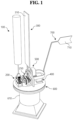
FIG. 1 is a perspective view showing a bladeless wind energy harvester according to an embodiment of the present invention. -
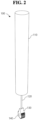
FIG. 2 is a perspective view showing a bluff body of the bladeless wind energy harvester according to the embodiment of the present invention. -
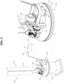
FIG. 3 is a perspective view showing a gear box of the wind turbine according to the embodiment of the present invention. -
FIG. 4 is a perspective view showing a mechanical rectifier of the wind turbine according to the embodiment of the present invention. -
FIG. 5 is an enlarged perspective view showing a distance adjuster and a plate of the bladeless wind energy harvester according to the embodiment of the present invention. -
FIGs. 6a to 6c are perspective views showing the pendulum motion of the bluff body by means of the wind in the bladeless wind energy harvester according to the embodiment of the present invention. -
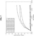
FIGs. 7 and8 are graphs showing voltages by Reynolds number per a bluff body diameter and a distance between the bluff body and an obstacle in the bladeless wind energy harvester according to the embodiment of the present invention. -
FIGs. 9 and 10 are top views showing other examples of the bluff body of the bladeless wind energy harvester according to the embodiment of the present invention. -
FIGs. 11a and 11b are top views showing other examples of the obstacle of the bladeless wind energy harvester according to the embodiment of the present invention. - Terms used in the specification will be explained briefly, and an embodiment of the present invention will be explained in detail.
- All terms as will be discussed later are defined in accordance with the functions of the present invention, but may be varied under the intention or regulation of a user or operator. Therefore, they should be defined on the basis of the whole scope of the present invention.
- In the description, when it is said that one portion is described as "includes" any component, one element further may include other components unless no specific description is suggested.
- Hereinafter, the embodiment of the present invention will be explained in detail with reference to the attached drawings to be easily understood by those of ordinary skill in the art. However, the present invention may be freely modified within the scope of the invention, without being limited to the embodiment as will be discussed later.
- Technical problems and solutions of the present invention and the effectiveness of the present invention will be included in the detailed description as will be described below and the attached drawings. Objects, characteristics and advantages of the present invention will be more clearly understood from the detailed description as will be described below and the attached drawings.
- Flow-induced vibration (FIV) is a physical phenomenon widely observed in an engineering field, which is generated by aerodynamic instability or vortex shedding when a fluid blows across a thin structure. That is, a wind turbine of the present invention is an FIV energy harvesting device that extracts (harvests) energy from a flow field therearound and thus provides power. While a fluid is flowing along a bluff body, a vortex distance or Karman vortex distance is generated from a vortex region. Periodical vortex shedding from the surface of the bluff body applies asymmetrical pressure to the structure and thus produces alternating aerodynamic forces. Such alternating aerodynamic forces cause the vibrations of the bluff body, and the vibrations are used to produce power.
- Hereinafter, an embodiment of the present invention will be described in detail with referent to the attached drawings.
- Referring to
FIG. 1 , a wind turbine according to an embodiment of the present invention includes abluff body 100, anobstacle 300 spaced apart from thebluff body 100 and having a larger plane section than thebluff body 100, agear box 200 located below thebluff body 100 to rotatably support thebluff body 100 and transferring the rotation of thebluff body 100, and agenerator 400 connected to thegear box 200 by means of a shaft, wherein thebluff body 100 and theobstacle 300 are parallel to each other so that thebluff body 100 rotates by means of vortices generated from the collision between wind and theobstacle 300 to allow thegenerator 400 to produce electric energy. - First, the
bluff body 100 is provided. Thebluff body 100 is a massive object that rotates by means of the vortices generated from the interaction between wind and theobstacle 300 and thus transmits wind energy in the form of a pendulum motion. For example, referring toFIG. 2 , thebluff body 100 includes a cylindricalmain body 110, aconnection bar 120 extending from the underside of themain body 110, apartial gear 130 located on the underside of theconnection bar 120 and having at least a portion as a toothed gear, and arotary shaft 140 located at the center of thepartial gear 130 to allow thebluff body 100 to be rotatable. In this case, therotary shaft 140 is supportedly inserted into arotary shaft hole 211 as will be discussed later, and thebluff body 100 performs the pendulum motion around therotary shaft 140. As thebluff body 100 rotates, further, thepartial gear 130 rotates to allow afirst transmission gear 220 orsecond transmission gear 230 as will be discussed later to rotate, and then, the rotation of thebluff body 100 is converted into unidirectional rotation through amechanical rectifier 250 as will be discussed later, so that the rotation of thebluff body 100 is transferred to thegenerator 400 to allow electric energy to be generated from thegenerator 400. - Next, the
gear box 200 is provided. Thegear box 200 transfers the rotation of thebluff body 100 generated by the vortices of wind to thegenerator 400 in the form of a rotational motion. For example, referring toFIG. 3 , thegear box 200 includes arotational frame 210 having an empty space formed therein and thefirst transmission gear 220 and thesecond transmission gear 230 arranged side by side in such a way as to be rotatable inside therotational frame 210, and therotational frame 210 has therotary shaft hole 211 formed on an upper portion thereof in such a way as to insert therotary shaft 140 thereinto and rotatably support therotary shaft 140 and bearings. In this case, thepartial gear 130 is located engaged with thefirst transmission gear 220 and thesecond transmission gear 230, so that the rotation of thepartial gear 130 is transferred to thefirst transmission gear 220 and thesecond transmission gear 230. - Further, the
gear box 200 includes themechanical rectifier 250 adapted to convert the rotation of the shaft into unidirectional rotation. That is, while themechanical rectifier 250 is receiving the pendulum motion of thebluff body 100, it converts rotations of one direction and the other direction into the unidirectional rotation and transfers the converted rotation to thegenerator 400. In detail, themechanical rectifier 250 converts a clockwise rotation and a counterclockwise rotation into the unidirectional rotation to allow the shaft connecting thegear box 200 and thegenerator 400 to rotate unidirectionally. - In more detail, if the
mechanical rectifier 250 is not provided, the shaft performs a reciprocal rotation, not a unidirectional rotation, as thepartial gear 130 moves. That is, if thepartial gear 130 rotates in a clockwise direction, thefirst transmission gear 220 and thesecond transmission gear 230 rotate in counterclockwise directions to allow the shaft to rotate in the counterclockwise direction, and if thepartial gear 130 is returned to its original position or rotates in the counterclockwise direction, thefirst transmission gear 220 and thesecond transmission gear 230 rotate in the clockwise directions to allow the shaft to rotate in the clockwise direction. That is, themechanical rectifier 250 converts the reciprocal rotation into the unidirectional rotation to allow the rotation in a given direction to be transferred to thegenerator 400. In this case, themechanical rectifier 250 may further include a planetary gear (not shown) adapted to increase a rotational speed. - For example, referring to
FIG. 4 , themechanical rectifier 250 includes afirst shaft 251 rotating by receiving the rotational motion of thepartial gear 130 through the first transmission gear, afirst gear 252 rotating together with thefirst shaft 251, asecond gear 253 rotating together with thefirst shaft 251 in such a way to be spaced apart from thefirst gear 252, athird gear 255 located close to thefirst gear 252 in such a way as to rotate together with thefirst gear 252 in the opposite direction to the rotational direction of thefirst gear 252, asecond shaft 256 rotating together with thethird gear 255 or rotating by receiving the rotational motion of thepartial gear 130 or the rotational motion of thesecond transmission gear 230, afourth gear 257 rotating together with thesecond shaft 256 in such a way as to be arranged on the same line as thesecond gear 253, anoutput gear 258 located between thesecond gear 253 and thefourth gear 257, anoutput shaft 259 rotating together with theoutput gear 258 to transfer the rotational motion to thegenerator 400, andunidirectional clutches 254 located on thesecond gear 253 and thefourth gear 257 to allow thesecond gear 253 and thefourth gear 257 to rotate unidirectionally. - Accordingly, the rotational motion of the
partial gear 130 is transferred to thefirst transmission gear 220 and then transferred to thefirst gear 252 through thefirst shaft 251. In this case, the clockwise rotational motion of thefirst shaft 251 rotates thefirst gear 252 in the clockwise direction, and also, theunidirectional clutch 254 located on thesecond gear 253 rotates in the clockwise direction. As theunidirectional clutch 254 closed in the clockwise direction is coupled to thesecond gear 253, the clockwise rotational motion of thefirst shaft 251 is transferred to thesecond gear 253. Contrarily, the counterclockwise rotational motion of thethird gear 255 operating through the clockwise rotational motion of thefirst gear 252 is transferred to theunidirectional clutch 254 located on thefourth gear 257 through thesecond shaft 256. In this case, also, as theunidirectional clutch 254 located on thefourth gear 257 is closed in the clockwise direction and open in the counterclockwise direction, the counterclockwise rotational motion of thesecond shaft 256 is not transferred to thefourth gear 257. Accordingly, theoutput gear 258 rotates in the counterclockwise direction, and also, theoutput shaft 259 rotates in the counterclockwise direction. - Contrarily, the counterclockwise rotational motion of the
first shaft 251 rotates thefirst gear 252 in the counterclockwise direction. As theunidirectional clutch 254 located on thesecond gear 253 is open in the counterclockwise direction, the counterclockwise rotational motion of thefirst shaft 251 is not transferred to thesecond gear 253. Contrarily, thethird gear 255 rotates in the clockwise direction through the counterclockwise rotational motion of thefirst gear 252, and the clockwise rotation of thethird gear 255 is transferred to theunidirectional clutch 254 located on thefourth gear 257 through thesecond shaft 256. In this case, also, as theunidirectional clutch 254 located on thefourth gear 257 is closed in the clockwise direction, thefourth gear 257 rotates in the clockwise direction through the clockwise rotational motion of thesecond shaft 256. Accordingly, theoutput gear 258 rotates in the counterclockwise direction through the clockwise rotation of thefourth gear 257, and also, theoutput shaft 259 rotates in the counterclockwise direction. As a result, theoutput shaft 259 rotates unidirectionally, that is, only in the counterclockwise direction, without being influenced by the rotational direction of the shaft. That is, the reciprocal rotation of thepartial gear 130 through the pendulum motion of thebluff body 100 is transferred to theoutput shaft 259, so that as theoutput shaft 259 rotates only in the counterclockwise direction, the electric power can be generated consistently through thegenerator 400. - Next, the
obstacle 300 is provided. Theobstacle 300 serves to collide against wind to induce the wind to generate vortices. For example, theobstacle 300 has the shape of a plate with a longer horizontal length than a diameter of themain body 110. That is, theobstacle 300 includes aplane section portion 310 having the shape of a rectangular plate andcoupling bars 320 coupled between the underside of theplane section portion 310 and aslider 510 as will be discussed later. Further, theobstacle 300 is linearly transferred by means of adistance adjuster 500 as will be discussed later, so that a distance between theobstacle 300 and thebluff body 100 can be adjusted. Furthermore, theobstacle 300 is arranged parallel to thebluff body 100 and aflow guide 700 as will be discussed later in a straight line. - Next, referring to
FIG. 5 , the bladeless wind energy harvester according to the present invention further includes thedistance adjuster 500 coupled to theobstacle 300 and linearly transferring theobstacle 300 to adjust a distance between thebluff body 100 and theobstacle 300. That is, thedistance adjuster 500 is configured to allow theobstacle 300 to linearly reciprocate in a direction toward thebluff body 100 so that the distance between theobstacle 300 and thebluff body 100 is adjustable. For example, thedistance adjuster 500 includes theslider 510 coupled to the coupling bars 320, ascrew 520 inserted into theslider 510 and thus rotating, linear bearings 521, astep motor 530 connected to thescrew 520 to provide a driving force for rotating thescrew 520, and arigid frame 540 coupled to aplate 600 as will be discussed later and supporting thestep motor 530. If thestep motor 530 rotates in one direction, thescrew 520 rotates in one direction to allow theslider 510 to be linearly transferred in the direction toward thebluff body 100, and if thestep motor 530 rotates in the other direction, thescrew 520 rotates in the other direction to allow theslider 510 to be linearly transferred in the opposite direction to the direction toward thebluff body 100. As a result, the distance between theobstacle 300 and thebluff body 100 is adjustable. - Next, the bladeless wind energy harvester according to the present invention further includes the
plate 600 supporting thegear box 200 and theobstacle 300 in such a way as to be rotatable around a shaft vertical to the surface of the ground. For example, theplate 600 has the shape of a disc and is supported against a trust bearing 620 in such a way as to rotate by means of theflow guide 700 as will be discussed later according to the direction of the wind. That is, theplate 600 includes aplate body 610 having the shape of a disc, asupport body 620 located under theplate body 610 to support theplate body 610, and the trust bearing 630 located between theplate body 610 and thesupport body 620 to rotate theplate body 610. In this case, a vertical rotational shaft is provided for theplate body 610, so that theplate body 610 rotates around the rotational shaft vertical to the surface of the ground. - Further, the bladeless wind energy harvester according to the present invention includes the
flow guide 700 arranged side by side with thebluff body 100 and theobstacle 300 above theplate 600 in such a way as to have a plane section in a vertical direction to theobstacle 300, and if the wind collides against theflow guide 700, theplate 600 rotates to allow theobstacle 300 to be placed in a direction toward the wind. That is, theobstacle 300 and theflow guide 700 are arranged in directions vertical to each other. In detail, theplane section portion 310 of theobstacle 300 and aplane section portion 710 of theflow guide 700 are arranged vertical to each other to allow theobstacle 300 to be placed in a direction toward the wind. For example, referring toFIG. 5 , if wind blows from the bottom on the left side toward the top on the right side, that is, if wind blows toward a thin side portion of theobstacle 300 in a direction vertical to the direction toward theplane section portion 310 of theobstacle 300, the number of vortices generated is reduced. In this case, as the wind blowing in the direction vertical to the direction toward theplane section portion 310 of theobstacle 300 collides against theplane section portion 710 of theflow guide 700, theplate body 610 rotates in the counterclockwise direction to allow theplane section portion 310 of theobstacle 300 to be placed in the direction toward the wind. As a result, theplate body 610 rotates according to real-time flow of wind to allow theplane section portion 310 of theobstacle 300 to be placed in the direction toward the wind, thereby enabling consistent power generation. - Referring to
FIGs. 6a to 6c , accordingly, thebluff body 100 rotates through the vortices generated by the collision between the wind and theobstacle 300, and the rotational motion of thebluff body 100 is transferred to thegenerator 400 through thegear box 200. - In this case, referring to
FIGs. 7 and8 , a ratio of a distance Z between thebluff body 100 and theobstacle 300 to a diameter D of thebluff body 100 is 0.3 to 0.4. In detail, if a ratio of the distance Z between thebluff body 100 and theobstacle 300 to the diameter D of thebluff body 100 is 0.36, the highest power generation efficiency is obtained. - Further, the bladeless wind energy harvester according to the present invention obtains high power generation efficiency as vortices having high Reynolds number are generated. Accordingly, the cross-sectional shape of the
bluff body 100 may be made to a shape capable of inducing the wind to have a turbulent flow. - For example, referring to
FIGs. 9c and 10 , abluff body 102 has the cross-sectional shape of '', so that the Reynolds number of the wind colliding against the
bluff body 102 increases, thereby improving power generation efficiency. - Further, referring to
FIG. 11a , anobstacle 301 located on the downstream flow of thebluff body 100 is bent at the central portion thereof, so that the wind colliding against theobstacle 301 is prevented from flowing outward and thus induced to flow toward thebluff body 100. - Furthermore, referring to
FIG. 11b , anobstacle 302 located on the downstream flow of thebluff body 100 is entirely rounded around the central portion thereof, so that the wind colliding against theobstacle 302 is prevented from flowing outward and thus induced to flow toward thebluff body 100. - As described above, the bladeless wind energy harvester according to the present invention is capable to use the vibrations produced by vortex induced vibration of the bluff body and consequently rotation of generator to convert wind energy into electric energy, thereby advantageously improving the energy generation efficiency.
- Although the embodiments above have been described in considerable detail, numerous variations and modifications will become apparent to those skilled in the art once the above disclosure is fully appreciated.
- While the present invention has been described with reference to the particular illustrative embodiments, it is not to be restricted by the embodiments but only by the appended claims. It is to be appreciated that those skilled in the art can change or modify the embodiments without departing from the scope and spirit of the present invention. It is therefore intended that the scope of the invention be limited not by this detailed description, but rather by the claims appended hereto.
- According to the present invention, such new geometric shapes for the bluff body are suggested, and the obstacle behind the bluff body is also utilized, so that a distance between the obstacle and the bluff body is optimized to improve the energy generation efficiency of the FIV-based energy harvesting device. According to the present invention, the bluff body has the optimized geometric structure, and if the flat obstacle behind the bluff body is utilized, further, vibration amplitudes increase to raise the harvested energy. That is, as the Reynolds number increases, an amount of power generated increases. The optimal distance of Z/D is 0.36, and as the obstacle is used at the optimal distance, the highest amount of power generated through the geometric structure suggested when the Reynolds number = 16000 is larger by 26% than the cylindrical bluff body having the obstacle. The cylindrical bluff body utilizing the obstacle has an amount of power generated larger by about 85% than that utilizing no obstacle. If the width of the obstacle is equal to the diameter of the cylindrical bluff body, the bladeless wind energy harvester has better performance. The geometric structure of the bladeless wind energy harvester with the suggested obstacle allows the largest number of vortices to be generated. In the case of a convex model with the obstacle, the highest value of turbulent flow energy is greater by 41% than a simple model, which is obtained by unstable aerodynamic force applied to the model. According to an instant flow pattern and a speed vector image, vortex shedding of the convex model with the obstacle increases the vortex shedding of the obstacle behind the model, and the vortices shed are added to produce stronger vortices. To produce manual control for wake parameters and suggest a new generation bladeless wind energy harvester, lastly, there is suggested a new configuration wherein the obstacle is located on the downstream of the bluff body providing important influences on induced voltages. The geometric shape of the bluff body, which is inspired by nature, has an optimal width, and further, the obstacle is located at an optimal distance from the bluff body, so that the bladeless wind energy harvester according to the present invention can have an amount of harvested energy of about 86% larger than the existing bladeless wind turbine.
Claims (5)
- A bladeless wind energy harvester comprising:a bluff body;an obstacle spaced apart from the bluff body and having a larger plane section than the bluff body;a gear box located below the bluff body to rotatably support the bluff body and transferring the rotation of the bluff body; anda generator connected to the gear box by means of a shaft,wherein the bluff body and the obstacle are parallel to each other so that the bluff body oscillates by means of vortices generated from the interaction of wind with the bluff body and obstacle to allow the generator to generate electric energy.
- The bladeless wind energy harvester according to claim 1, wherein the gear box comprises a mechanical rectifier adapted to convert the reciprocal rotations of the shaft into a unidirectional rotation.
- The bladeless wind energy harvester according to claim 1, further comprising a distance adjuster coupled to the obstacle and transferring the obstacle to adjust a distance between the bluff body and the obstacle.
- The bladeless wind energy harvester according to claim 1, further comprising a plate supporting the gear box and the obstacle in such a way as to be rotatable around a shaft vertical to the surface of the ground.
- The bladeless wind energy harvester according to claim 4, further comprising a flow guide attached to the foundation plate that holds the bluff body and the obstacle in such a way as to have a plane section in a vertical direction to the obstacle, wherein if the wind blows different with the flow guide direction, the foundation plate rotates to allow the obstacle to be placed in a direction toward the wind.
Applications Claiming Priority (2)
| Application Number | Priority Date | Filing Date | Title |
|---|---|---|---|
| KR20230165698 | 2023-11-24 | ||
| KR1020240027111A KR102927115B1 (en) | 2023-11-24 | 2024-02-26 | Wind power generator |
Publications (3)
| Publication Number | Publication Date |
|---|---|
| EP4560137A1 true EP4560137A1 (en) | 2025-05-28 |
| EP4560137C0 EP4560137C0 (en) | 2025-12-03 |
| EP4560137B1 EP4560137B1 (en) | 2025-12-03 |
Family
ID=93455810
Family Applications (1)
| Application Number | Title | Priority Date | Filing Date |
|---|---|---|---|
| EP24211464.3A Active EP4560137B1 (en) | 2023-11-24 | 2024-11-07 | Bladeless wind energy harvester |
Country Status (3)
| Country | Link |
|---|---|
| US (1) | US20250172123A1 (en) |
| EP (1) | EP4560137B1 (en) |
| CN (1) | CN120042744A (en) |
Citations (3)
| Publication number | Priority date | Publication date | Assignee | Title |
|---|---|---|---|---|
| US20060064972A1 (en) * | 2004-01-14 | 2006-03-30 | Allen James J | Bluff body energy converter |
| KR100960042B1 (en) | 2009-11-24 | 2010-05-31 | 손정희 | Wind generator with blade diretion angle controller |
| WO2016116657A1 (en) * | 2015-01-23 | 2016-07-28 | Medrano Sánchez Carlos | System to obtain energy from a fluid |
Family Cites Families (21)
| Publication number | Priority date | Publication date | Assignee | Title |
|---|---|---|---|---|
| US640003A (en) * | 1899-02-01 | 1899-12-26 | Judson Stuart Landon | Wind-motor. |
| DE433513C (en) * | 1924-05-17 | 1926-09-06 | Export Imp & Commission G M B | Wind engine |
| US7199480B2 (en) * | 2004-04-15 | 2007-04-03 | Halliburton Energy Services, Inc. | Vibration based power generator |
| US7208845B2 (en) * | 2004-04-15 | 2007-04-24 | Halliburton Energy Services, Inc. | Vibration based power generator |
| US20080048455A1 (en) * | 2006-08-25 | 2008-02-28 | Matthew Eli Carney | Energy capture in flowing fluids |
| US7839009B2 (en) * | 2008-02-28 | 2010-11-23 | Philip A Rink | Buoyant blade free stream tidal power device |
| WO2009110997A2 (en) * | 2008-03-04 | 2009-09-11 | Johnnie Williams | Oscillating windmill |
| ES2374233B8 (en) * | 2010-08-02 | 2013-02-27 | Deutecno S.L. | RESONANT AIRCRAFT BY VORTICITY. |
| DK177654B1 (en) * | 2012-06-20 | 2014-02-03 | Subcpartner Holding Aps | WAVE POWER CONVERTER |
| US10641243B2 (en) * | 2014-10-06 | 2020-05-05 | Vortex Bladeless, S.L. | Electrical power generator harnessing a swaying movement of a pole and including a system for generating a magnetic repulsion force |
| SK288982B6 (en) * | 2015-11-10 | 2022-08-10 | Archee, s.r.o | Apparatus for obtaining mechanical work and/or generating power from fluid flows |
| WO2017174161A1 (en) * | 2016-04-07 | 2017-10-12 | Vortex Bladeless, S.L. | Electrical power generator |
| JP2020509278A (en) * | 2017-02-17 | 2020-03-26 | ヴォルテックス・ブラデレス・エス・エルVortex Bladeless, S.L. | Generator |
| US10367434B2 (en) * | 2017-05-30 | 2019-07-30 | Saudi Arabian Oil Company | Harvesting energy from fluid flow |
| WO2019075445A1 (en) * | 2017-10-13 | 2019-04-18 | In Esther | Method and apparatus for harvesting electrical energy from air flow in a moving system |
| US11187205B2 (en) * | 2017-11-07 | 2021-11-30 | Graf S.p A. | Resonance wind turbine |
| CN108111058B (en) * | 2018-01-08 | 2019-04-16 | 河海大学 | A kind of modified piezoelectric cantilever vortex-induced vibration power generator |
| US10982648B2 (en) * | 2019-03-30 | 2021-04-20 | Ehsan Azadi Yazdi | Bladeless wind turbine with a telescoping natural frequency tuning mechanism |
| CN111852771B (en) * | 2020-07-29 | 2022-03-08 | 西南石油大学 | Small wind power generation device and method adaptive to wind direction and wind speed |
| CN114421854B (en) * | 2021-12-24 | 2024-06-18 | 国网江苏省电力有限公司电力科学研究院 | A micro-power wind-solar hybrid energy-harvesting power generation device and energy-harvesting method |
| KR102713792B1 (en) * | 2022-09-29 | 2024-10-04 | 부산대학교 산학협력단 | Energy harvester using both roll or pitch motion |
-
2024
- 2024-09-26 CN CN202411346460.XA patent/CN120042744A/en active Pending
- 2024-10-23 US US18/924,390 patent/US20250172123A1/en active Pending
- 2024-11-07 EP EP24211464.3A patent/EP4560137B1/en active Active
Patent Citations (3)
| Publication number | Priority date | Publication date | Assignee | Title |
|---|---|---|---|---|
| US20060064972A1 (en) * | 2004-01-14 | 2006-03-30 | Allen James J | Bluff body energy converter |
| KR100960042B1 (en) | 2009-11-24 | 2010-05-31 | 손정희 | Wind generator with blade diretion angle controller |
| WO2016116657A1 (en) * | 2015-01-23 | 2016-07-28 | Medrano Sánchez Carlos | System to obtain energy from a fluid |
Non-Patent Citations (3)
| Title |
|---|
| LI H T ET AL: "Dynamics and performance evaluation of a vortex-induced vibration energy harvester with hybrid bluff body", SMART MATERIALS AND STRUCTURES, IOP PUBLISHING LTD., BRISTOL, GB, vol. 32, no. 4, 16 March 2023 (2023-03-16), XP020446777, ISSN: 0964-1726, [retrieved on 20230316], DOI: 10.1088/1361-665X/ACC1B8 * |
| LIAO WEILIN ET AL: "A Novel Magnetic-Coupling Non-Contact Piezoelectric Wind Energy Harvester With a Compound-Embedded Structure", IEEE SENSORS JOURNAL, IEEE, USA, vol. 22, no. 9, 23 March 2022 (2022-03-23), pages 8428 - 8438, XP011907130, ISSN: 1530-437X, [retrieved on 20220323], DOI: 10.1109/JSEN.2022.3161833 * |
| WANG JUNLEI ET AL: "Wake galloping energy harvesting in heat exchange systems under the influence of ash deposition", ENERGY, ELSEVIER, AMSTERDAM, NL, vol. 253, 6 May 2022 (2022-05-06), XP087087728, ISSN: 0360-5442, [retrieved on 20220506], DOI: 10.1016/J.ENERGY.2022.124175 * |
Also Published As
| Publication number | Publication date |
|---|---|
| US20250172123A1 (en) | 2025-05-29 |
| EP4560137C0 (en) | 2025-12-03 |
| CN120042744A (en) | 2025-05-27 |
| EP4560137B1 (en) | 2025-12-03 |
Similar Documents
| Publication | Publication Date | Title |
|---|---|---|
| US4387318A (en) | Piezoelectric fluid-electric generator | |
| EP2738925B1 (en) | Dynamo | |
| US9447774B2 (en) | Non-rotating wind energy generator | |
| US6688842B2 (en) | Vertical axis wind engine | |
| US20080048455A1 (en) | Energy capture in flowing fluids | |
| US8535008B2 (en) | Turbine and compressor employing tubercle leading edge rotor design | |
| US7224077B2 (en) | Bluff body energy converter | |
| US7762776B2 (en) | Vortex shedding cyclical propeller | |
| US20120049523A1 (en) | Wind jet turbine ii | |
| US20140001761A1 (en) | Adaptive hydrokinetic energy harvesting | |
| CN109312713B (en) | dynamo | |
| CA2863612A1 (en) | Bluff body turbine and method | |
| Zhang et al. | Vertical axis wind turbine with individual active blade pitch control | |
| US20240218853A1 (en) | Energy Harvesting Device, System and Method of Manufacture | |
| KR101269109B1 (en) | Buliding integrated wind power generator | |
| EP4560137B1 (en) | Bladeless wind energy harvester | |
| US9541058B2 (en) | Energy converters and energy conversion systems | |
| EP0147391A1 (en) | Piezoelectric fluid-electric generator | |
| CN106014761B (en) | A kind of self-oscillation aerofoil profile power generator using vortex shedding effect | |
| JP2010520414A (en) | Hubless windmill | |
| KR102927115B1 (en) | Wind power generator | |
| JP7497260B2 (en) | Vertical axis wind turbines and vertical axis wind power generation equipment | |
| Farthing | Vertical axis wind turbine induced velocity vector theory | |
| Olinger et al. | Performance characteristics of a 1 kw scale kite-powered system | |
| Holmes | Energy harvesting from fluid flows |
Legal Events
| Date | Code | Title | Description |
|---|---|---|---|
| PUAI | Public reference made under article 153(3) epc to a published international application that has entered the european phase |
Free format text: ORIGINAL CODE: 0009012 |
|
| STAA | Information on the status of an ep patent application or granted ep patent |
Free format text: STATUS: REQUEST FOR EXAMINATION WAS MADE |
|
| 17P | Request for examination filed |
Effective date: 20241107 |
|
| AK | Designated contracting states |
Kind code of ref document: A1 Designated state(s): AL AT BE BG CH CY CZ DE DK EE ES FI FR GB GR HR HU IE IS IT LI LT LU LV MC ME MK MT NL NO PL PT RO RS SE SI SK SM TR |
|
| GRAP | Despatch of communication of intention to grant a patent |
Free format text: ORIGINAL CODE: EPIDOSNIGR1 |
|
| STAA | Information on the status of an ep patent application or granted ep patent |
Free format text: STATUS: GRANT OF PATENT IS INTENDED |
|
| RIC1 | Information provided on ipc code assigned before grant |
Ipc: F03D 5/06 20060101AFI20250722BHEP Ipc: F03D 9/25 20160101ALI20250722BHEP |
|
| INTG | Intention to grant announced |
Effective date: 20250813 |
|
| GRAS | Grant fee paid |
Free format text: ORIGINAL CODE: EPIDOSNIGR3 |
|
| GRAA | (expected) grant |
Free format text: ORIGINAL CODE: 0009210 |
|
| STAA | Information on the status of an ep patent application or granted ep patent |
Free format text: STATUS: THE PATENT HAS BEEN GRANTED |
|
| AK | Designated contracting states |
Kind code of ref document: B1 Designated state(s): AL AT BE BG CH CY CZ DE DK EE ES FI FR GB GR HR HU IE IS IT LI LT LU LV MC ME MK MT NL NO PL PT RO RS SE SI SK SM TR |
|
| REG | Reference to a national code |
Ref country code: CH Ref legal event code: F10 Free format text: ST27 STATUS EVENT CODE: U-0-0-F10-F00 (AS PROVIDED BY THE NATIONAL OFFICE) Effective date: 20251203 Ref country code: GB Ref legal event code: FG4D |
|
| REG | Reference to a national code |
Ref country code: DE Ref legal event code: R096 Ref document number: 602024001525 Country of ref document: DE |
|
| REG | Reference to a national code |
Ref country code: IE Ref legal event code: FG4D |
|
| U01 | Request for unitary effect filed |
Effective date: 20251222 |
|
| U07 | Unitary effect registered |
Designated state(s): AT BE BG DE DK EE FI FR IT LT LU LV MT NL PT RO SE SI Effective date: 20260109 |
|
| PG25 | Lapsed in a contracting state [announced via postgrant information from national office to epo] |
Ref country code: ES Free format text: LAPSE BECAUSE OF FAILURE TO SUBMIT A TRANSLATION OF THE DESCRIPTION OR TO PAY THE FEE WITHIN THE PRESCRIBED TIME-LIMIT Effective date: 20251203 |
|
| PG25 | Lapsed in a contracting state [announced via postgrant information from national office to epo] |
Ref country code: NO Free format text: LAPSE BECAUSE OF FAILURE TO SUBMIT A TRANSLATION OF THE DESCRIPTION OR TO PAY THE FEE WITHIN THE PRESCRIBED TIME-LIMIT Effective date: 20260303 |
|
| PG25 | Lapsed in a contracting state [announced via postgrant information from national office to epo] |
Ref country code: HR Free format text: LAPSE BECAUSE OF FAILURE TO SUBMIT A TRANSLATION OF THE DESCRIPTION OR TO PAY THE FEE WITHIN THE PRESCRIBED TIME-LIMIT Effective date: 20251203 |
|
| PG25 | Lapsed in a contracting state [announced via postgrant information from national office to epo] |
Ref country code: RS Free format text: LAPSE BECAUSE OF FAILURE TO SUBMIT A TRANSLATION OF THE DESCRIPTION OR TO PAY THE FEE WITHIN THE PRESCRIBED TIME-LIMIT Effective date: 20260303 |
|
| PG25 | Lapsed in a contracting state [announced via postgrant information from national office to epo] |
Ref country code: PL Free format text: LAPSE BECAUSE OF FAILURE TO SUBMIT A TRANSLATION OF THE DESCRIPTION OR TO PAY THE FEE WITHIN THE PRESCRIBED TIME-LIMIT Effective date: 20251203 |