EP4560120A1 - Oil filler tube assembly for aircraft engine - Google Patents
Oil filler tube assembly for aircraft engine Download PDFInfo
- Publication number
- EP4560120A1 EP4560120A1 EP24214477.2A EP24214477A EP4560120A1 EP 4560120 A1 EP4560120 A1 EP 4560120A1 EP 24214477 A EP24214477 A EP 24214477A EP 4560120 A1 EP4560120 A1 EP 4560120A1
- Authority
- EP
- European Patent Office
- Prior art keywords
- filler tube
- piston
- oil
- seal
- top end
- Prior art date
- Legal status (The legal status is an assumption and is not a legal conclusion. Google has not performed a legal analysis and makes no representation as to the accuracy of the status listed.)
- Pending
Links
Images



Classifications
-
- F—MECHANICAL ENGINEERING; LIGHTING; HEATING; WEAPONS; BLASTING
- F01—MACHINES OR ENGINES IN GENERAL; ENGINE PLANTS IN GENERAL; STEAM ENGINES
- F01M—LUBRICATING OF MACHINES OR ENGINES IN GENERAL; LUBRICATING INTERNAL COMBUSTION ENGINES; CRANKCASE VENTILATING
- F01M11/00—Component parts, details or accessories, not provided for in, or of interest apart from, groups F01M1/00 - F01M9/00
- F01M11/04—Filling or draining lubricant of or from machines or engines
-
- F—MECHANICAL ENGINEERING; LIGHTING; HEATING; WEAPONS; BLASTING
- F01—MACHINES OR ENGINES IN GENERAL; ENGINE PLANTS IN GENERAL; STEAM ENGINES
- F01D—NON-POSITIVE DISPLACEMENT MACHINES OR ENGINES, e.g. STEAM TURBINES
- F01D25/00—Component parts, details, or accessories, not provided for in, or of interest apart from, other groups
- F01D25/18—Lubricating arrangements
- F01D25/183—Sealing means
-
- F—MECHANICAL ENGINEERING; LIGHTING; HEATING; WEAPONS; BLASTING
- F01—MACHINES OR ENGINES IN GENERAL; ENGINE PLANTS IN GENERAL; STEAM ENGINES
- F01M—LUBRICATING OF MACHINES OR ENGINES IN GENERAL; LUBRICATING INTERNAL COMBUSTION ENGINES; CRANKCASE VENTILATING
- F01M11/00—Component parts, details or accessories, not provided for in, or of interest apart from, groups F01M1/00 - F01M9/00
- F01M11/10—Indicating devices; Other safety devices
- F01M11/12—Indicating devices; Other safety devices concerning lubricant level
-
- F—MECHANICAL ENGINEERING; LIGHTING; HEATING; WEAPONS; BLASTING
- F02—COMBUSTION ENGINES; HOT-GAS OR COMBUSTION-PRODUCT ENGINE PLANTS
- F02C—GAS-TURBINE PLANTS; AIR INTAKES FOR JET-PROPULSION PLANTS; CONTROLLING FUEL SUPPLY IN AIR-BREATHING JET-PROPULSION PLANTS
- F02C7/00—Features, components parts, details or accessories, not provided for in, or of interest apart form groups F02C1/00 - F02C6/00; Air intakes for jet-propulsion plants
- F02C7/12—Cooling of plants
- F02C7/16—Cooling of plants characterised by cooling medium
-
- F—MECHANICAL ENGINEERING; LIGHTING; HEATING; WEAPONS; BLASTING
- F16—ENGINEERING ELEMENTS AND UNITS; GENERAL MEASURES FOR PRODUCING AND MAINTAINING EFFECTIVE FUNCTIONING OF MACHINES OR INSTALLATIONS; THERMAL INSULATION IN GENERAL
- F16N—LUBRICATING
- F16N19/00—Lubricant containers for use in lubricators or lubrication systems
- F16N19/003—Indicating oil level
-
- F—MECHANICAL ENGINEERING; LIGHTING; HEATING; WEAPONS; BLASTING
- F01—MACHINES OR ENGINES IN GENERAL; ENGINE PLANTS IN GENERAL; STEAM ENGINES
- F01M—LUBRICATING OF MACHINES OR ENGINES IN GENERAL; LUBRICATING INTERNAL COMBUSTION ENGINES; CRANKCASE VENTILATING
- F01M11/00—Component parts, details or accessories, not provided for in, or of interest apart from, groups F01M1/00 - F01M9/00
- F01M11/04—Filling or draining lubricant of or from machines or engines
- F01M11/0408—Sump drainage devices, e.g. valves, plugs
- F01M2011/0416—Plugs
- F01M2011/0433—Plugs with a device defining the lubricant level during filling
-
- F—MECHANICAL ENGINEERING; LIGHTING; HEATING; WEAPONS; BLASTING
- F01—MACHINES OR ENGINES IN GENERAL; ENGINE PLANTS IN GENERAL; STEAM ENGINES
- F01M—LUBRICATING OF MACHINES OR ENGINES IN GENERAL; LUBRICATING INTERNAL COMBUSTION ENGINES; CRANKCASE VENTILATING
- F01M11/00—Component parts, details or accessories, not provided for in, or of interest apart from, groups F01M1/00 - F01M9/00
- F01M11/04—Filling or draining lubricant of or from machines or engines
- F01M2011/0491—Filing cap with special features
-
- F—MECHANICAL ENGINEERING; LIGHTING; HEATING; WEAPONS; BLASTING
- F05—INDEXING SCHEMES RELATING TO ENGINES OR PUMPS IN VARIOUS SUBCLASSES OF CLASSES F01-F04
- F05D—INDEXING SCHEME FOR ASPECTS RELATING TO NON-POSITIVE-DISPLACEMENT MACHINES OR ENGINES, GAS-TURBINES OR JET-PROPULSION PLANTS
- F05D2220/00—Application
- F05D2220/30—Application in turbines
- F05D2220/32—Application in turbines in gas turbines
- F05D2220/323—Application in turbines in gas turbines for aircraft propulsion, e.g. jet engines
-
- F—MECHANICAL ENGINEERING; LIGHTING; HEATING; WEAPONS; BLASTING
- F05—INDEXING SCHEMES RELATING TO ENGINES OR PUMPS IN VARIOUS SUBCLASSES OF CLASSES F01-F04
- F05D—INDEXING SCHEME FOR ASPECTS RELATING TO NON-POSITIVE-DISPLACEMENT MACHINES OR ENGINES, GAS-TURBINES OR JET-PROPULSION PLANTS
- F05D2230/00—Manufacture
- F05D2230/72—Maintenance
-
- F—MECHANICAL ENGINEERING; LIGHTING; HEATING; WEAPONS; BLASTING
- F05—INDEXING SCHEMES RELATING TO ENGINES OR PUMPS IN VARIOUS SUBCLASSES OF CLASSES F01-F04
- F05D—INDEXING SCHEME FOR ASPECTS RELATING TO NON-POSITIVE-DISPLACEMENT MACHINES OR ENGINES, GAS-TURBINES OR JET-PROPULSION PLANTS
- F05D2240/00—Components
- F05D2240/55—Seals
- F05D2240/58—Piston ring seals
-
- F—MECHANICAL ENGINEERING; LIGHTING; HEATING; WEAPONS; BLASTING
- F05—INDEXING SCHEMES RELATING TO ENGINES OR PUMPS IN VARIOUS SUBCLASSES OF CLASSES F01-F04
- F05D—INDEXING SCHEME FOR ASPECTS RELATING TO NON-POSITIVE-DISPLACEMENT MACHINES OR ENGINES, GAS-TURBINES OR JET-PROPULSION PLANTS
- F05D2260/00—Function
- F05D2260/60—Fluid transfer
- F05D2260/608—Aeration, ventilation, dehumidification or moisture removal of closed spaces
Definitions
- the disclosure relates generally to oil systems of aircraft engines and, more particularly, to systems and methods used for determining a level of oil in an oil tank of such engines and for filling the oil tank.
- Aircraft engines such as gas turbine engines, include an oil system for distributing an oil to required portions of the engine for lubrication and/or cooling purposes.
- oil may be directed to and from a bearing cavity of the aircraft engine. It may be required to add some oil in an oil tank of the oil system.
- a filler tube may be used. The filler tube is closed off with a cap and a dipstick is secured to the cap. The dipstick is used to determine a level of oil in the oil tank. In some cases, a volume of air in the filler tube may cause a false reading on the dipstick. Improvements are therefore sought.
- an oil filler assembly for an aircraft engine, comprising: a filler tube extending from a bottom end to a top end; a valve having a tube side fluidly connected to the filler tube and a tank side fluidly connectable to an oil tank; a cap removably secured to the top end of the filler tube; a dipstick secured to the cap and extending into the filler tube towards the bottom end; and a piston secured to the dipstick and sized to be received in the filler tube between the top end and the valve, the piston having: a sealing configuration in which the piston sealingly engages the filler tube to fluidly disconnect the top end from the valve, the piston being in the sealing configuration when the cap is secured to the top end of the filler tube; and a venting configuration in which the piston permits fluid communication between the top end and the valve, the piston being in the venting configuration when the cap is moved away from the top end of the filler tube.
- the oil filler assembly may include any of the following features, in any combinations.
- the valve includes a ball and a seat, a movement of the piston away from the top end of the filler tube and towards the valve increases a pressure inside the filler tube to unseat the ball from the seat.
- the piston includes a body secured to the dipstick and a seal mounted to the body, the seal movable relative to the body to move the piston between the sealing configuration and the venting configuration.
- the body defines an annular groove, the seal in register with the annular groove.
- the body has a top face facing the cap and a bottom face facing away from the cap, the body defining a vent passage extending from an inlet to an outlet, the inlet located into the annular groove, the outlet defined by the bottom face.
- the seal is movable within the annular groove, the seal overlapping the inlet of the vent passage in the sealing configuration of the piston, the seal offset from the inlet of the vent passage in the venting configuration of the piston.
- the piston includes a secondary body slidably engaged to the body, the secondary body received in the annular groove, the secondary body defining a second annular groove, the seal received in the second annular groove.
- the secondary body has a top face facing the top end and a bottom face opposite the top face, the secondary body defining a vent passage extending from the top face to the bottom face, the body defining a shoulder facing the top face of the secondary body, the top face of the secondary body in abutment against the shoulder and the shoulder overlapping the vent passage in the sealing configuration of the piston, the top face spaced apart from the shoulder in the venting configuration of the piston.
- the filler tube has a wall having a section defining a frustoconical shape, the seal being an annular elastomeric web extending from the body to a peripheral edge, the peripheral edge in abutment against the section of the wall in the sealing configuration, the peripheral edge spaced apart from the wall in the venting configuration thereby defining an air passage between the peripheral edge and the wall of the filler tube.
- an aircraft engine comprising: an oil tank; a filler tube; a valve between the oil tank and the filler tube, the valve operable to selectively fluidly connect the filler tube to the oil tank; a cap removably securable to a top end of the filler tube; a dipstick secured to the cap and extending into the filler tube; and a piston secured to the dipstick and sized to be received in the filler tube, the piston sealingly engaged to a wall of the filler tube and fluidly disconnecting the top end of the filler tube from the valve when the cap is secured to the top end of the filler tube, the piston permitting fluid communication between the top end of the filler tube and the valve when the cap is moved away from the top end of the filler tube.
- the aircraft engine may include any of the following features, in any combinations.
- the valve includes a ball and a seat, a movement of the piston away from the top end of the filler tube and towards the valve increases a pressure inside the filler tube to unseat the ball from the seat thereby opening the valve to allow oil to flow from the oil tank into the filler tube.
- the piston includes a body secured to the dipstick and a seal mounted to the body, the seal movable relative to the body.
- the body defines an annular groove, the seal in register with the annular groove.
- the body has a top face facing the cap and a bottom face facing away from the cap, the body defining a vent passage extending from an inlet to an outlet, the inlet located into the annular groove, the outlet defined by the bottom face.
- the seal is movable within the annular groove, the seal overlapping the inlet of the vent passage when the cap is secured to the top end, the seal offset from the inlet of the vent passage in the cap is detached from the top end.
- the piston includes a secondary body slidably engaged to the body, the secondary body received in the annular groove, the secondary body defining a second annular groove, the seal received in the second annular groove.
- the secondary body has a top face facing the top and a bottom face opposite the top face, the secondary body defining a vent passage extending from the top face to the bottom face, the body defining a shoulder facing the top face, the top face of the secondary body in abutment against the shoulder and the shoulder overlapping the vent passage when the cap is secured to the top end, the top face spaced apart from the shoulder when the cap is detached from the top end.
- the filler tube has a wall having a section defining a frustoconical shape, the seal being an annular elastomeric web extending from the body to a peripheral edge, the peripheral edge in abutment against the section of the wall when the cap is secured to the top end, the peripheral edge spaced apart from the wall when the cap is detached from the top end thereby defining an air passage between the peripheral edge and the wall of the filler tube.
- a method for mitigating detrimental effects of air in a filler tube the filler tube fluidly connected to an oil tank via a valve, the filler tube closable with a cap secured to a dipstick, the filler tube fluidly disconnectable from an environment with a piston secured to the dipstick, the method comprising: upon removing the cap from a top end of the filler tube, breaking a seal defined between the piston and the filler tube; and upon inserting the dipstick in the filler tube, increasing a pressure in the filler tube via a sealing engagement defined between the piston and the filler tube, the pressure sufficient to open the valve.
- the increasing of the pressure includes closing a vent defined by a body of the piston with a seal movable relative to the body.
- Fig. 1 illustrates an aircraft engine, such as a gas turbine engine 10, of a type preferably provided for use in subsonic flight.
- the gas turbine engine 10 includes in serial flow communication a fan 12 through which ambient air is propelled, a compressor section 14 for pressurizing the air, a combustor 16 in which the compressed air is mixed with fuel and ignited for generating an annular stream of hot combustion gases, and a turbine section 18 for extracting energy from the combustion gases.
- the fan 12, the compressor section 14, and the turbine section 18 are rotatable about a central axis 11 of the gas turbine engine 10.
- the gas turbine engine 10 includes an oil system 100 for lubricating and/or cooling components in need of lubrication and/or cooling.
- these components may include, for instance, a bearing cavity 13 of the gas turbine engine 10, gearboxes, and so on.
- the bearing cavity 13 may include a plurality of bearing cavities for the different bearings of the gas turbine engine 10.
- the bearing cavity 13 is an enclosure surrounding a shaft (e.g., highpressure shaft, low-pressure shaft) of the gas turbine engine 10 and containing one or more bearing(s).
- the bearing cavity 13 is supplied with a flow of oil F1 during operation to maintain proper lubricating conditions for the bearings. Used oil is scavenged out of the bearing cavity 13 and returned back to a reservoir.
- the oil system 100 includes an oil circuit 102 including conduits 104 for flowing the oil.
- a pump 106 is used for driving the flow of the oil F1 in the oil circuit 102.
- the oil system 100 includes an oil tank 108 that contains a volume of the oil.
- the oil system 100 is operable to draw oil from the oil tank 108 and to flow this oil within the conduits 104 to distribute the oil into the different components requiring oil. Oil is scavenged and flown back to the oil tank 108.
- the oil system 100 may also include additional components such as valve(s), heat exchangers, filters, scavenged pump(s), etc.
- a filler tube assembly 200 may be used.
- the filler tube assembly 200 is fluidly connected to the oil tank 108 at or proximate a bottom of the oil tank 108. Therefore, the filler tube assembly 200 and the oil tank 108 may define a U-shape structure.
- the level of oil in the oil tank 108 denoted by line S in Fig. 2 , may be the same in the oil tank 108 as in the filler tube assembly 200.
- the filler tube assembly 200 may include a dipstick that defines markings indicating if the level of oil is adequate, or if more oil is to be added in the oil tank 108.
- the filler tube assembly 200 includes a filler tube 201 extending from a bottom end 201A to a top end 201B.
- the bottom end 201A is fluidly connected to the oil tank 108 as shown in Fig. 2 .
- the top end 201B of the filler tube assembly 200 is selectively open or close by a cap 202.
- the top end 201B defines an inlet of the oil tank 108 as it is via this port that oil may be added to the oil tank 108 in some embodiments.
- the cap 202 is used to close the top end 201B of the filler tube assembly 200 to avoid oil leaking out of the filler tube assembly 200 during flight.
- the cap 202 is therefore removably securable to the top end 201B. Any suitable mechanism, such as bayonet, threads, and so on may be used to removably secure the cap 202 to the filler tube 201.
- the filler tube assembly 200 includes a dipstick 203 secured to the cap 202 and extending into the filler tube 201 towards the bottom end 201A.
- the dipstick 203 is received within the filler tube 201 and has a length sufficient to be at least partially submerged in oil contained in the filler tube 201.
- the dipstick 203 may have markings on it indicating different levels of oil as known in the art.
- the filler tube assembly 200 includes a non-return valve 204 fluidly connected to the filler tube 201 proximate the bottom end 201A.
- the valve 204 is operable to selectively fluidly connect the filler tube 201 to the oil tank 108.
- the valve 204 has a tube side fluidly connected to the filler tube 201 and a tank side fluidly connected to the oil tank 108.
- valve 204 is used as a safety feature to keep the oil in the oil tank 108 during manoeuvre of the aircraft (e.g., pitch, roll, etc). Put differently, the purpose of this valve 204 is to protect loss of oil from the oil tank during flight if by inadvertence the cap was forgotten during oil replenishment.
- the valve 204 is depicted as a ball valve, but any other suitable valve may be used.
- the valve 204 includes a conduit 204A that extends from a seat 204B to a stopper 204C. A ball 204D is movably received within the conduit 204A between the seat 204B and the stopper 204C.
- the stopper 204C is closer to the bottom end 201A of the filler tube 201 than the seat 204B.
- the valve 204 is configured such that, if the aircraft makes a manoeuvre that causes oil to flow in the filler tube 201, the oil will push the ball 204D against the seat 204B thereby preventing oil from overflowing in the filler tube 201 and escaping to the environment if the cap is missing.
- the stopper 204C is used to prevent the ball 204D from leaving the conduit 204A.
- the greater height of oil in the oil tank 108 biases the ball 204D against the seat 204B thereby preventing oil from equilibrating between the filler tube 201 and the oil tank 108.
- this causes false reading of the oil level on the dipstick 203.
- the dipstick 203 might indicate that there is not enough oil in the oil tank 108 while this may not actually be the case.
- it may cause difficulties during oil replenishment since the ball may get stuck closed and oil cannot flow to the oil tank.
- the filler tube assembly 200 of the present disclosure may at least partially alleviate these drawbacks.
- the filler tube assembly 200 includes a piston 210 secured to the dipstick 203.
- the piston 210 may be directly secured to the dipstick 203 as shown in Fig. 3 or, alternatively, secured to the dipstick 203 via the cap 202 for instance.
- the piston 210 is received in the filler tube 201 between the top end 201B of the filler tube 201 and the valve 204 and is operable to sealingly engage a wall of the filler tube 201 as will be explained below.
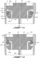
- the piston 210 has a venting configuration ( Fig. 4A ) in which the piston 210 permits fluid communication between the top end 201B of the filler tube 201 and the valve 204, and has a sealing configuration ( Fig. 4B ) in which the piston 210 sealingly engages the filler tube 201 to fluidly disconnect the top end 201B of the filler tube 201 from the valve 204.
- the piston 210 is in the venting configuration when the cap 202 is moved away from the top end 201B of the filler tube, and is in the sealing configuration when the cap 202 is moved towards the top end 201B of the filler tube 201.
- the piston 210 is sealingly engaged to a wall of the filler tube 201 and fluidly disconnects the top end 201B of the filler tube 201 from the valve 204 when the cap 202 is secured to the top end 201B of the filler tube 201.
- the piston 210 permits fluid communication between the top end 201B of the filler tube 201 and the valve 204 when the cap 202 is detached from the top end 201B of the filler tube 201 and spaced apart therefrom.
- the increasing air pressure pushes on the ball 204D to unseat the ball 204D from the seat 204B thereby opening the valve 204 to allow a portion of the oil to flow from the oil tank 108 into the filler tube 201. This may therefore alleviate the effects of the volume of air in the filler tube 201 expanding with a decrease of atmospheric pressure.
- the oil pressure on opposite sides of the ball 204D may equilibrate such that the ball 204D is "floating" between the seat and the stopper. By “floating” it is implied that the ball 204D is not biased against any of the seat or the stopper.
- the ball when checking the oil level with the dipstick, the ball may be dislodge from its seat, as it might be stuck in a closed position from the previously explained phenomenon (differential pressure at altitude, air expansion, and so on). Therefore, this may allow proper oil level check by dislodging the ball and proper oil replenishment since the ball valve may not be stuck.
- the piston 210 has a body 211 secured to the dipstick 203.
- the body 211 may be annular and the dipstick 203 extend through a bore defined through the body 211.
- Other configurations are contemplated.
- the body 211 has a top face 211A facing the cap 202 and a bottom face 211B facing away from the cap 202.
- the body 211 defines an annular groove 211C, which is defined by a peripheral face of the body 211.
- the annular groove 211C is located between the top face 211A and the bottom face 211B.
- the piston 210 further includes a seal 212 that is received into the annular groove 211C.
- the seal 212 may be, for instance, an O-ring or any suitable sealing member and may be made of an elastomeric material.
- the seal 212 is in register with the annular groove 211C and compressed between a wall of the filler tube 201 and the body 211 of the piston.
- the body 211 further defines a vent passage 211D, or simply vent, two vent passages in the embodiment shown, but more or less may be used.
- the vent passages 211D have inlets 211E communicating with the annular groove 211C and outlets 211F defined by the bottom face 211B.
- the inlets 211E are opening to the annular groove 211C. In other words, the inlets 211E are in register with the annular groove 211C.
- the seal 212 is smaller than the annular groove 211C to allow the seal 212 to move relative to the body 211. Movements of the seal 212 relative to the body 211 moves the piston 210 between the sealing configuration and the venting configuration. More specifically, and as shown in Fig. 4A , when a user separates the cap 202 from the top end 201B of the filler tube 201, the dipstick 203 and the piston 210 are pulled in an upward direction D1 to pull the dipstick 203 out of the filler tube 201 to allow the user to read the oil level.
- the seal 212 stays substantially immobile until it is abutted by a lower shoulder 211G that axially delimits the annular groove 211C.
- This relative movement between the seal 212 and the body 211 creates an offset between the seal 212 and the inlets 211E of the vent passages 211D.
- the seal 212 is offset from the inlets 211E of the vent passages 211D in the venting configuration of the piston 210. Therefore, an environment E outside the filler tube 201 is fluidly connected to a volume located between the piston 210 and the valve 204 through the vent passages 211D. This therefore permits air to flow from the environment E into this volume thereby preventing a suctioning effect that might pull oil out of the oil tank 108 into the filler tube 201 and which might cause false reading of the oil level.
- the piston 210 is inserted into the filler tube 201 and moved along a downward direction D2 opposite the upward direction D1.
- the frictional engagement between the seal 212 and the wall of the filler tube 201 opposes movements of the seal 212 to cause a relative movement between the seal 212 and the body 211 of the piston 210 until the seal 212 is abutted by an upper shoulder 211H located above the annular groove 211C.
- This relative movement causes the seal 212 to become in register with the inlets 211E of the vent passages 211D such that the seal 212 overlaps the inlets 211E to close the vent passages 211D.
- the seal 212 overlaps the inlets 211E of the vent passages 211D in the sealing configuration of the piston 210.
- the volume of air between the piston 210 and the valve 204 is fluidly disconnected from the environment E outside the filler tube 201 and further motion of the piston 210 along the downwards direction D2 compresses air located in this volume to unseat the ball 204D of the valve 204 from the seat 204B ( Fig. 3 ) to permit a volume of oil to leave the oil tank 108 and enters the filler tube 201.
- the drawbacks caused by the air in the volume may thus be at least partially avoided.
- the piston 310 includes a body 311 and a secondary body 313 disposed around the body 311 and slidably engaged to the body 311.
- the secondary body 313 is received within an annular groove 311A defined by the body 311.
- the secondary body 313 is movable relative to the body 311 within the annular groove 311A and between a top shoulder 311B and a bottom shoulder 311C.
- the top shoulder 311B faces downwardly away from the cap 202 ( Fig. 3 ).
- the secondary body 313 defines an annular groove 313A that receives the seal 312, which is compressed between the wall of the filler tube 201 and the secondary body 313.
- the secondary body 313 defines vent passages 313B, two shown but more or less may be used, that extend from a top face to a bottom face of the secondary body 313. Inlets of the vent passages 313B are facing the top shoulder 311B and are radially overlapped by the top shoulder 311B.
- the top face of the secondary body 313 is in abutment against the top shoulder 311B and the top shoulder 311B overlaps the vent passages 313B thereby fluidly disconnecting the environment E from the volume of air located below the piston 310.
- a sealing surface with a sealing feature e.g., gasket
- the seal 312 opposes this movement thereby creating a space between the top shoulder 311B and the secondary body 313 to open the vent passages 313B thereby fluidly connecting the environment E to the volume. This may prevent the suctioning effect as discussed above.
- the top face of the secondary body 313 is spaced apart from the top shoulder 311B. It will be appreciated that the bottom shoulder 311C is dimensioned to not overlap the vent passages 313B.
- the seal 312 may be an O-ring.
- the seal 412 may be a V-cup seal.
- the V-cup seal may define two legs spaced apart by a gap. The two legs oriented downwardly such that when pushing the piston 310 into the filler tube 201, the two legs tend to separate from one another to increase a sealing effect with the filler tube 201. When pulling the piston 310 out of the filler tube 201, the two legs may move toward one another to decrease the sealing effect to facilitate the removal of the piston 310.
- the piston 510 includes a body 511 and a seal 512 mounted to the body 511.
- the piston 510 and the seal 512 are two parts of a single monolithic member, which may be made of an elastomeric material. These two parts may alternatively be secured together via any suitable means.
- the seal 512 is located within a frustoconical section 201C of the filler tube 201.
- the seal 512 may be regarded as an annular elastomeric web extending from the body 511 to a peripheral edge 512A. The peripheral edge 512A abuts the frustoconical section 201C of the wall in the sealing configuration.
- the peripheral edge 512A eventually becomes in register with a portion of the frustoconical section 201C of the filler tube 201 that has a greater diameter and the peripheral edge 512A no longer contacts the wall of the filler tube 201. This creates a gap between the peripheral edge 512A and the filler tube 201 to fluidly connect the environment E to the volume below the piston 510. At some point, the web of the seal 512 may invert as shown in Fig. 7B .
- the peripheral edge 512A When re-inserting the dipstick 203 and the piston 510, the peripheral edge 512A may abut the frustoconical section 201C of the filler tube 201 to fluidly disconnect the environment E from the volume below the piston 510. Further downward motion of the piston 510 pushes on the air to open the valve 204 as described herein above. Therefore, in this embodiment, the peripheral edge 512A is spaced apart from the wall in the venting configuration thereby defining an air passage between the peripheral edge 512A and the wall of the filler tube 201. The peripheral edge 512A is in abutment against the wall of the filler tube 201 in the sealing configuration.
- the method 800 includes upon removing the cap 202 from the top end 201B of the filler tube 201, breaking a seal defined between the piston 210, 310, 510 and the filler tube 201 thereby preventing a suction of oil from the oil tank 108 into the filler tube 201 at 802; and upon inserting the dipstick 203 in the filler tube 201, increasing a pressure in the filler tube 201 via a sealing engagement defined between the piston 210, 310, 510 and the filler tube 201 thereby opening the valve 204 to allow a portion of the oil to flow from the oil tank 108 and into the filler tube 201 at 804.
- the pressure is sufficient to open the valve 204.
- the increasing of the pressure at 804 includes closing the vents defined by the body of the piston 210, 310, 510 with the seal 212, 312, 412, 512 movable relative to the body 211, 311, 511.
- connections are set forth between elements in the preceding description and in the drawings. It is noted that these connections are general and, unless specified otherwise, may be direct or indirect and that this specification is not intended to be limiting in this respect.
- a coupling between two or more entities may refer to a direct connection or an indirect connection.
- An indirect connection may incorporate one or more intervening entities.
- the term "connected” or “coupled to” may therefore include both direct coupling (in which two elements that are coupled to each other contact each other) and indirect coupling (in which at least one additional element is located between the two elements).
- indefinite article “a” as used herein with reference to a particular element is intended to encompass “one or more” such elements, and similarly the use of the definite article “the” in reference to a particular element is not intended to exclude the possibility that multiple of such elements may be present.
- top and bottom are in relation to an elevation from a ground when an aircraft equipped with the gas turbine engine 10 is on the ground.
Landscapes
- Engineering & Computer Science (AREA)
- General Engineering & Computer Science (AREA)
- Mechanical Engineering (AREA)
- Chemical & Material Sciences (AREA)
- Combustion & Propulsion (AREA)
- Lubrication Details And Ventilation Of Internal Combustion Engines (AREA)
Abstract
Description
- The disclosure relates generally to oil systems of aircraft engines and, more particularly, to systems and methods used for determining a level of oil in an oil tank of such engines and for filling the oil tank.
- Aircraft engines, such as gas turbine engines, include an oil system for distributing an oil to required portions of the engine for lubrication and/or cooling purposes. For example, oil may be directed to and from a bearing cavity of the aircraft engine. It may be required to add some oil in an oil tank of the oil system. To do so, a filler tube may be used. The filler tube is closed off with a cap and a dipstick is secured to the cap. The dipstick is used to determine a level of oil in the oil tank. In some cases, a volume of air in the filler tube may cause a false reading on the dipstick. Improvements are therefore sought.
- In one aspect of the present invention, there is provided an oil filler assembly for an aircraft engine, comprising: a filler tube extending from a bottom end to a top end; a valve having a tube side fluidly connected to the filler tube and a tank side fluidly connectable to an oil tank; a cap removably secured to the top end of the filler tube; a dipstick secured to the cap and extending into the filler tube towards the bottom end; and a piston secured to the dipstick and sized to be received in the filler tube between the top end and the valve, the piston having: a sealing configuration in which the piston sealingly engages the filler tube to fluidly disconnect the top end from the valve, the piston being in the sealing configuration when the cap is secured to the top end of the filler tube; and a venting configuration in which the piston permits fluid communication between the top end and the valve, the piston being in the venting configuration when the cap is moved away from the top end of the filler tube.
- The oil filler assembly may include any of the following features, in any combinations.
- In an embodiment of the above, the valve includes a ball and a seat, a movement of the piston away from the top end of the filler tube and towards the valve increases a pressure inside the filler tube to unseat the ball from the seat.
- In an embodiment according to any of the previous embodiments, the piston includes a body secured to the dipstick and a seal mounted to the body, the seal movable relative to the body to move the piston between the sealing configuration and the venting configuration.
- In an embodiment according to any of the previous embodiments, the body defines an annular groove, the seal in register with the annular groove.
- In an embodiment according to any of the previous embodiments, the body has a top face facing the cap and a bottom face facing away from the cap, the body defining a vent passage extending from an inlet to an outlet, the inlet located into the annular groove, the outlet defined by the bottom face.
- In an embodiment according to any of the previous embodiments, the seal is movable within the annular groove, the seal overlapping the inlet of the vent passage in the sealing configuration of the piston, the seal offset from the inlet of the vent passage in the venting configuration of the piston.
- In an embodiment according to any of the previous embodiments, the piston includes a secondary body slidably engaged to the body, the secondary body received in the annular groove, the secondary body defining a second annular groove, the seal received in the second annular groove.
- In an embodiment according to any of the previous embodiments, the secondary body has a top face facing the top end and a bottom face opposite the top face, the secondary body defining a vent passage extending from the top face to the bottom face, the body defining a shoulder facing the top face of the secondary body, the top face of the secondary body in abutment against the shoulder and the shoulder overlapping the vent passage in the sealing configuration of the piston, the top face spaced apart from the shoulder in the venting configuration of the piston.
- In an embodiment according to any of the previous embodiments, the filler tube has a wall having a section defining a frustoconical shape, the seal being an annular elastomeric web extending from the body to a peripheral edge, the peripheral edge in abutment against the section of the wall in the sealing configuration, the peripheral edge spaced apart from the wall in the venting configuration thereby defining an air passage between the peripheral edge and the wall of the filler tube.
- In another aspect of the present invention, there is provided an aircraft engine, comprising: an oil tank; a filler tube; a valve between the oil tank and the filler tube, the valve operable to selectively fluidly connect the filler tube to the oil tank; a cap removably securable to a top end of the filler tube; a dipstick secured to the cap and extending into the filler tube; and a piston secured to the dipstick and sized to be received in the filler tube, the piston sealingly engaged to a wall of the filler tube and fluidly disconnecting the top end of the filler tube from the valve when the cap is secured to the top end of the filler tube, the piston permitting fluid communication between the top end of the filler tube and the valve when the cap is moved away from the top end of the filler tube.
- The aircraft engine may include any of the following features, in any combinations.
- In an embodiment of the above, the valve includes a ball and a seat, a movement of the piston away from the top end of the filler tube and towards the valve increases a pressure inside the filler tube to unseat the ball from the seat thereby opening the valve to allow oil to flow from the oil tank into the filler tube.
- In an embodiment according to any of the previous embodiments, the piston includes a body secured to the dipstick and a seal mounted to the body, the seal movable relative to the body.
- In an embodiment according to any of the previous embodiments, the body defines an annular groove, the seal in register with the annular groove.
- In an embodiment according to any of the previous embodiments, the body has a top face facing the cap and a bottom face facing away from the cap, the body defining a vent passage extending from an inlet to an outlet, the inlet located into the annular groove, the outlet defined by the bottom face.
- In an embodiment according to any of the previous embodiments, the seal is movable within the annular groove, the seal overlapping the inlet of the vent passage when the cap is secured to the top end, the seal offset from the inlet of the vent passage in the cap is detached from the top end.
- In an embodiment according to any of the previous embodiments, the piston includes a secondary body slidably engaged to the body, the secondary body received in the annular groove, the secondary body defining a second annular groove, the seal received in the second annular groove.
- In an embodiment according to any of the previous embodiments, the secondary body has a top face facing the top and a bottom face opposite the top face, the secondary body defining a vent passage extending from the top face to the bottom face, the body defining a shoulder facing the top face, the top face of the secondary body in abutment against the shoulder and the shoulder overlapping the vent passage when the cap is secured to the top end, the top face spaced apart from the shoulder when the cap is detached from the top end.
- In an embodiment according to any of the previous embodiments, the filler tube has a wall having a section defining a frustoconical shape, the seal being an annular elastomeric web extending from the body to a peripheral edge, the peripheral edge in abutment against the section of the wall when the cap is secured to the top end, the peripheral edge spaced apart from the wall when the cap is detached from the top end thereby defining an air passage between the peripheral edge and the wall of the filler tube.
- In yet another aspect of the present invention, there is provided a method for mitigating detrimental effects of air in a filler tube, the filler tube fluidly connected to an oil tank via a valve, the filler tube closable with a cap secured to a dipstick, the filler tube fluidly disconnectable from an environment with a piston secured to the dipstick, the method comprising: upon removing the cap from a top end of the filler tube, breaking a seal defined between the piston and the filler tube; and upon inserting the dipstick in the filler tube, increasing a pressure in the filler tube via a sealing engagement defined between the piston and the filler tube, the pressure sufficient to open the valve.
- In an embodiment of the above, the increasing of the pressure includes closing a vent defined by a body of the piston with a seal movable relative to the body.
- Reference is now made to the accompanying figures in which:
-
Fig. 1 is a schematic cross sectional view of an aircraft engine provided in the form of a gas turbine engine; -
Fig. 2 is a schematic view of an oil system in accordance with one embodiment for the aircraft engine ofFig. 1 ; -
Fig. 3 is a cutaway view of a filler tube assembly in accordance with one embodiment for the oil system ofFig. 2 ; -
Fig. 4A is an enlarged view of a portion of the filler tube assembly ofFig. 3 in a venting configuration; -
Fig. 4B is an enlarged view of a portion of the filler tube assembly ofFig. 3 in a sealing configuration; -
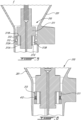
Fig. 5 is an enlarged view of another embodiment of a piston for the filler tube assembly ofFig. 3 shown in a sealing configuration; -
Fig. 6 is a cutaway view of a variant of the filler tube assembly ofFig. 5 ; -
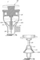
Fig. 7A is a cutaway view of a filler tube assembly in accordance with yet another embodiment for the oil system ofFig. 2 , the filler tube assembly shown in a sealing configuration; -
Fig. 7B is a three dimensional view of a piston of the filler tube assembly of Fig. 8A; and -
Fig. 8 is a flowchart illustrating steps of a method for mitigating detrimental effects of air in a filler tube. -
Fig. 1 illustrates an aircraft engine, such as agas turbine engine 10, of a type preferably provided for use in subsonic flight. Thegas turbine engine 10 includes in serial flow communication afan 12 through which ambient air is propelled, acompressor section 14 for pressurizing the air, acombustor 16 in which the compressed air is mixed with fuel and ignited for generating an annular stream of hot combustion gases, and aturbine section 18 for extracting energy from the combustion gases. Thefan 12, thecompressor section 14, and theturbine section 18 are rotatable about acentral axis 11 of thegas turbine engine 10. - It will be appreciated that the principle of the present disclosure may be applied to any aircraft engines including a lubrication system or a cooling system, such as turbofan, turboprop, turboshaft, internal combustion engines, and so on.
- Referring to
Figs. 1 and 2 , thegas turbine engine 10 includes anoil system 100 for lubricating and/or cooling components in need of lubrication and/or cooling. These components may include, for instance, abearing cavity 13 of thegas turbine engine 10, gearboxes, and so on. Thebearing cavity 13 may include a plurality of bearing cavities for the different bearings of thegas turbine engine 10. Thebearing cavity 13 is an enclosure surrounding a shaft (e.g., highpressure shaft, low-pressure shaft) of thegas turbine engine 10 and containing one or more bearing(s). Thebearing cavity 13 is supplied with a flow of oil F1 during operation to maintain proper lubricating conditions for the bearings. Used oil is scavenged out of thebearing cavity 13 and returned back to a reservoir. - In the embodiment shown, the
oil system 100 includes anoil circuit 102 includingconduits 104 for flowing the oil. Apump 106 is used for driving the flow of the oil F1 in theoil circuit 102. Theoil system 100 includes anoil tank 108 that contains a volume of the oil. Theoil system 100 is operable to draw oil from theoil tank 108 and to flow this oil within theconduits 104 to distribute the oil into the different components requiring oil. Oil is scavenged and flown back to theoil tank 108. Theoil system 100 may also include additional components such as valve(s), heat exchangers, filters, scavenged pump(s), etc. - In some cases, it may be required to verify a level of oil in the
oil tank 108. To do so, afiller tube assembly 200 may be used. Thefiller tube assembly 200 is fluidly connected to theoil tank 108 at or proximate a bottom of theoil tank 108. Therefore, thefiller tube assembly 200 and theoil tank 108 may define a U-shape structure. Hence, the level of oil in theoil tank 108, denoted by line S inFig. 2 , may be the same in theoil tank 108 as in thefiller tube assembly 200. As known in the art, thefiller tube assembly 200 may include a dipstick that defines markings indicating if the level of oil is adequate, or if more oil is to be added in theoil tank 108. - Referring now to
Fig. 3 , thefiller tube assembly 200 is described in more detail. Thefiller tube assembly 200 includes afiller tube 201 extending from abottom end 201A to atop end 201B. Thebottom end 201A is fluidly connected to theoil tank 108 as shown inFig. 2 . Thetop end 201B of thefiller tube assembly 200 is selectively open or close by acap 202. Thetop end 201B defines an inlet of theoil tank 108 as it is via this port that oil may be added to theoil tank 108 in some embodiments. Thecap 202 is used to close thetop end 201B of thefiller tube assembly 200 to avoid oil leaking out of thefiller tube assembly 200 during flight. Thecap 202 is therefore removably securable to thetop end 201B. Any suitable mechanism, such as bayonet, threads, and so on may be used to removably secure thecap 202 to thefiller tube 201. - The
filler tube assembly 200 includes adipstick 203 secured to thecap 202 and extending into thefiller tube 201 towards thebottom end 201A. Thedipstick 203 is received within thefiller tube 201 and has a length sufficient to be at least partially submerged in oil contained in thefiller tube 201. Thedipstick 203 may have markings on it indicating different levels of oil as known in the art. - In the embodiment shown, the
filler tube assembly 200 includes anon-return valve 204 fluidly connected to thefiller tube 201 proximate thebottom end 201A. Thevalve 204 is operable to selectively fluidly connect thefiller tube 201 to theoil tank 108. Thevalve 204 has a tube side fluidly connected to thefiller tube 201 and a tank side fluidly connected to theoil tank 108. - More specifically, the
valve 204 is used as a safety feature to keep the oil in theoil tank 108 during manoeuvre of the aircraft (e.g., pitch, roll, etc). Put differently, the purpose of thisvalve 204 is to protect loss of oil from the oil tank during flight if by inadvertence the cap was forgotten during oil replenishment. Thevalve 204 is depicted as a ball valve, but any other suitable valve may be used. Thevalve 204 includes aconduit 204A that extends from aseat 204B to astopper 204C. Aball 204D is movably received within theconduit 204A between theseat 204B and thestopper 204C. Thestopper 204C is closer to thebottom end 201A of thefiller tube 201 than theseat 204B. Thevalve 204 is configured such that, if the aircraft makes a manoeuvre that causes oil to flow in thefiller tube 201, the oil will push theball 204D against theseat 204B thereby preventing oil from overflowing in thefiller tube 201 and escaping to the environment if the cap is missing. Thestopper 204C is used to prevent theball 204D from leaving theconduit 204A. - It has been observed by the inventors of the present disclosure that, in some cases, a volume of air trapped inside the
filler tube 201 between thecap 202 and the oil expands when an altitude of the aircraft is increasing since atmospheric pressure is decreasing. The air, which now takes more space, pushes on the oil that leaves thefiller tube 201 to flow into theoil tank 108 through thevalve 204 by unseating theball 204D from theseat 204B. Then, when the aircraft is back on the ground, there is a discrepancy between the level of oil in theoil tank 108 and the level of oil in thefiller tube 201. It has been observed, that the greater height of oil in theoil tank 108 biases theball 204D against theseat 204B thereby preventing oil from equilibrating between thefiller tube 201 and theoil tank 108. In turn, this causes false reading of the oil level on thedipstick 203. Indeed, thedipstick 203 might indicate that there is not enough oil in theoil tank 108 while this may not actually be the case. Also, in some cases, it may cause difficulties during oil replenishment since the ball may get stuck closed and oil cannot flow to the oil tank. Thefiller tube assembly 200 of the present disclosure may at least partially alleviate these drawbacks. - Still referring to
Fig. 3 , in the embodiment shown, thefiller tube assembly 200 includes apiston 210 secured to thedipstick 203. Thepiston 210 may be directly secured to thedipstick 203 as shown inFig. 3 or, alternatively, secured to thedipstick 203 via thecap 202 for instance. Thepiston 210 is received in thefiller tube 201 between thetop end 201B of thefiller tube 201 and thevalve 204 and is operable to sealingly engage a wall of thefiller tube 201 as will be explained below. - Referring to
Figs. 4A and 4B , thepiston 210 has a venting configuration (Fig. 4A ) in which thepiston 210 permits fluid communication between thetop end 201B of thefiller tube 201 and thevalve 204, and has a sealing configuration (Fig. 4B ) in which thepiston 210 sealingly engages thefiller tube 201 to fluidly disconnect thetop end 201B of thefiller tube 201 from thevalve 204. Thepiston 210 is in the venting configuration when thecap 202 is moved away from thetop end 201B of the filler tube, and is in the sealing configuration when thecap 202 is moved towards thetop end 201B of thefiller tube 201. Put differently, thepiston 210 is sealingly engaged to a wall of thefiller tube 201 and fluidly disconnects thetop end 201B of thefiller tube 201 from thevalve 204 when thecap 202 is secured to thetop end 201B of thefiller tube 201. Thepiston 210 permits fluid communication between thetop end 201B of thefiller tube 201 and thevalve 204 when thecap 202 is detached from thetop end 201B of thefiller tube 201 and spaced apart therefrom. - Therefore, a movement of the
piston 210 away from thetop end 201B of thefiller tube 201 and towards thebottom end 201A of thefiller tube 201, such as when inserting thedipstick 203 for closing thetop end 201B with thecap 202, increases a pressure inside thefiller tube 201. The increasing air pressure pushes on theball 204D to unseat theball 204D from theseat 204B thereby opening thevalve 204 to allow a portion of the oil to flow from theoil tank 108 into thefiller tube 201. This may therefore alleviate the effects of the volume of air in thefiller tube 201 expanding with a decrease of atmospheric pressure. At some point, the oil pressure on opposite sides of theball 204D may equilibrate such that theball 204D is "floating" between the seat and the stopper. By "floating" it is implied that theball 204D is not biased against any of the seat or the stopper. - Put differently, when checking the oil level with the dipstick, the ball may be dislodge from its seat, as it might be stuck in a closed position from the previously explained phenomenon (differential pressure at altitude, air expansion, and so on). Therefore, this may allow proper oil level check by dislodging the ball and proper oil replenishment since the ball valve may not be stuck.
- In the embodiment shown, the
piston 210 has abody 211 secured to thedipstick 203. In the present embodiment, thebody 211 may be annular and thedipstick 203 extend through a bore defined through thebody 211. Other configurations are contemplated. In the depicted embodiment, thebody 211 has atop face 211A facing thecap 202 and abottom face 211B facing away from thecap 202. Thebody 211 defines anannular groove 211C, which is defined by a peripheral face of thebody 211. Theannular groove 211C is located between thetop face 211A and thebottom face 211B. Thepiston 210 further includes aseal 212 that is received into theannular groove 211C. Theseal 212 may be, for instance, an O-ring or any suitable sealing member and may be made of an elastomeric material. Theseal 212 is in register with theannular groove 211C and compressed between a wall of thefiller tube 201 and thebody 211 of the piston. - The
body 211 further defines avent passage 211D, or simply vent, two vent passages in the embodiment shown, but more or less may be used. Thevent passages 211D haveinlets 211E communicating with theannular groove 211C andoutlets 211F defined by thebottom face 211B. Theinlets 211E are opening to theannular groove 211C. In other words, theinlets 211E are in register with theannular groove 211C. - The
seal 212 is smaller than theannular groove 211C to allow theseal 212 to move relative to thebody 211. Movements of theseal 212 relative to thebody 211 moves thepiston 210 between the sealing configuration and the venting configuration. More specifically, and as shown inFig. 4A , when a user separates thecap 202 from thetop end 201B of thefiller tube 201, thedipstick 203 and thepiston 210 are pulled in an upward direction D1 to pull thedipstick 203 out of thefiller tube 201 to allow the user to read the oil level. Because of a frictional engagement between theseal 212 and the wall of thefiller tube 201, theseal 212 stays substantially immobile until it is abutted by alower shoulder 211G that axially delimits theannular groove 211C. This relative movement between theseal 212 and thebody 211 creates an offset between theseal 212 and theinlets 211E of thevent passages 211D. In other words, theseal 212 is offset from theinlets 211E of thevent passages 211D in the venting configuration of thepiston 210. Therefore, an environment E outside thefiller tube 201 is fluidly connected to a volume located between thepiston 210 and thevalve 204 through thevent passages 211D. This therefore permits air to flow from the environment E into this volume thereby preventing a suctioning effect that might pull oil out of theoil tank 108 into thefiller tube 201 and which might cause false reading of the oil level. - As shown in
Fig. 4B , when thedipstick 203 and thecap 202 are reinstalled, thepiston 210 is inserted into thefiller tube 201 and moved along a downward direction D2 opposite the upward direction D1. The frictional engagement between theseal 212 and the wall of thefiller tube 201 opposes movements of theseal 212 to cause a relative movement between theseal 212 and thebody 211 of thepiston 210 until theseal 212 is abutted by anupper shoulder 211H located above theannular groove 211C. This relative movement causes theseal 212 to become in register with theinlets 211E of thevent passages 211D such that theseal 212 overlaps theinlets 211E to close thevent passages 211D. Hence, theseal 212 overlaps theinlets 211E of thevent passages 211D in the sealing configuration of thepiston 210. - Therefore, as explained above, once the
seal 212 closes thevent passages 211D, the volume of air between thepiston 210 and thevalve 204 is fluidly disconnected from the environment E outside thefiller tube 201 and further motion of thepiston 210 along the downwards direction D2 compresses air located in this volume to unseat theball 204D of thevalve 204 from theseat 204B (Fig. 3 ) to permit a volume of oil to leave theoil tank 108 and enters thefiller tube 201. The drawbacks caused by the air in the volume may thus be at least partially avoided. - Referring now to
Fig. 5 , another embodiment of a piston is shown at 310. Thepiston 310 includes abody 311 and asecondary body 313 disposed around thebody 311 and slidably engaged to thebody 311. Thesecondary body 313 is received within anannular groove 311A defined by thebody 311. Thesecondary body 313 is movable relative to thebody 311 within theannular groove 311A and between atop shoulder 311B and abottom shoulder 311C. Thetop shoulder 311B faces downwardly away from the cap 202 (Fig. 3 ). Thesecondary body 313 defines anannular groove 313A that receives the seal 312, which is compressed between the wall of thefiller tube 201 and thesecondary body 313. - The
secondary body 313 defines ventpassages 313B, two shown but more or less may be used, that extend from a top face to a bottom face of thesecondary body 313. Inlets of thevent passages 313B are facing thetop shoulder 311B and are radially overlapped by thetop shoulder 311B. In the sealing configuration of thepiston 310 depicted inFig. 5 , the top face of thesecondary body 313 is in abutment against thetop shoulder 311B and thetop shoulder 311B overlaps thevent passages 313B thereby fluidly disconnecting the environment E from the volume of air located below thepiston 310. In some embodiments, a sealing surface with a sealing feature (e.g., gasket) may be included. When pulling thepiston 310 out of thefiller tube 201, as explained above, the seal 312 opposes this movement thereby creating a space between thetop shoulder 311B and thesecondary body 313 to open thevent passages 313B thereby fluidly connecting the environment E to the volume. This may prevent the suctioning effect as discussed above. Hence, in the venting configuration of thepiston 310, the top face of thesecondary body 313 is spaced apart from thetop shoulder 311B. It will be appreciated that thebottom shoulder 311C is dimensioned to not overlap thevent passages 313B. - As shown in
Fig. 5 , the seal 312 may be an O-ring. As shown inFig. 6 , theseal 412 may be a V-cup seal. The V-cup seal may define two legs spaced apart by a gap. The two legs oriented downwardly such that when pushing thepiston 310 into thefiller tube 201, the two legs tend to separate from one another to increase a sealing effect with thefiller tube 201. When pulling thepiston 310 out of thefiller tube 201, the two legs may move toward one another to decrease the sealing effect to facilitate the removal of thepiston 310. - Referring now to
Figs. 7A , another embodiment of a piston is shown at 510. Thepiston 510 includes abody 511 and aseal 512 mounted to thebody 511. In this embodiment, thepiston 510 and theseal 512 are two parts of a single monolithic member, which may be made of an elastomeric material. These two parts may alternatively be secured together via any suitable means. Theseal 512 is located within afrustoconical section 201C of thefiller tube 201. Theseal 512 may be regarded as an annular elastomeric web extending from thebody 511 to aperipheral edge 512A. Theperipheral edge 512A abuts thefrustoconical section 201C of the wall in the sealing configuration. - When removing the
cap 202 and pulling on thepiston 510, theperipheral edge 512A eventually becomes in register with a portion of thefrustoconical section 201C of thefiller tube 201 that has a greater diameter and theperipheral edge 512A no longer contacts the wall of thefiller tube 201. This creates a gap between theperipheral edge 512A and thefiller tube 201 to fluidly connect the environment E to the volume below thepiston 510. At some point, the web of theseal 512 may invert as shown inFig. 7B . When re-inserting thedipstick 203 and thepiston 510, theperipheral edge 512A may abut thefrustoconical section 201C of thefiller tube 201 to fluidly disconnect the environment E from the volume below thepiston 510. Further downward motion of thepiston 510 pushes on the air to open thevalve 204 as described herein above. Therefore, in this embodiment, theperipheral edge 512A is spaced apart from the wall in the venting configuration thereby defining an air passage between theperipheral edge 512A and the wall of thefiller tube 201. Theperipheral edge 512A is in abutment against the wall of thefiller tube 201 in the sealing configuration. - Referring to
Fig. 8 , a method for mitigating detrimental effects of air in thefiller tube 201 is shown at 800. Themethod 800 includes upon removing thecap 202 from thetop end 201B of thefiller tube 201, breaking a seal defined between thepiston filler tube 201 thereby preventing a suction of oil from theoil tank 108 into thefiller tube 201 at 802; and upon inserting thedipstick 203 in thefiller tube 201, increasing a pressure in thefiller tube 201 via a sealing engagement defined between thepiston filler tube 201 thereby opening thevalve 204 to allow a portion of the oil to flow from theoil tank 108 and into thefiller tube 201 at 804. The pressure is sufficient to open thevalve 204. - In some embodiments, the increasing of the pressure at 804 includes closing the vents defined by the body of the
piston seal body - It is noted that various connections are set forth between elements in the preceding description and in the drawings. It is noted that these connections are general and, unless specified otherwise, may be direct or indirect and that this specification is not intended to be limiting in this respect. A coupling between two or more entities may refer to a direct connection or an indirect connection. An indirect connection may incorporate one or more intervening entities. The term "connected" or "coupled to" may therefore include both direct coupling (in which two elements that are coupled to each other contact each other) and indirect coupling (in which at least one additional element is located between the two elements).
- It is further noted that various method or process steps for embodiments of the present disclosure are described in the following description and drawings. The description may present the method and/or process steps as a particular sequence. However, to the extent that the method or process does not rely on the particular order of steps set forth herein, the method or process should not be limited to the particular sequence of steps described. As one of ordinary skill in the art would appreciate, other sequences of steps may be possible. Therefore, the particular order of the steps set forth in the description should not be construed as a limitation.
- Furthermore, no element, component, or method step in the present disclosure is intended to be dedicated to the public regardless of whether the element, component, or method step is explicitly recited in the claims. As used herein, the terms "comprises", "comprising", or any other variation thereof, are intended to cover a non-exclusive inclusion, such that a process, method, article, or apparatus that comprises a list of elements does not include only those elements but may include other elements not expressly listed or inherent to such process, method, article, or apparatus.
- While various aspects of the present disclosure have been disclosed, it will be apparent to those of ordinary skill in the art that many more embodiments and implementations are possible within the scope of the present disclosure. For example, the present disclosure as described herein includes several aspects and embodiments that include particular features. Although these particular features may be described individually, it is within the scope of the present disclosure that some or all of these features may be combined with any one of the aspects and remain within the scope of the present disclosure. References to "various embodiments," "one embodiment," "an embodiment," "an example embodiment," etc., indicate that the embodiment described may include a particular feature, structure, or characteristic, but every embodiment may not necessarily include the particular feature, structure, or characteristic. Moreover, such phrases are not necessarily referring to the same embodiment. The use of the indefinite article "a" as used herein with reference to a particular element is intended to encompass "one or more" such elements, and similarly the use of the definite article "the" in reference to a particular element is not intended to exclude the possibility that multiple of such elements may be present.
- In the context of the present disclosure, the expressions "top" and "bottom" are in relation to an elevation from a ground when an aircraft equipped with the
gas turbine engine 10 is on the ground. - The embodiments described in this document provide non-limiting examples of possible implementations of the present technology. Upon review of the present disclosure, a person of ordinary skill in the art will recognize that changes may be made to the embodiments described herein without departing from the scope of the present technology. Yet further modifications could be implemented by a person of ordinary skill in the art in view of the present disclosure, which modifications would be within the scope of the present technology.
Claims (12)
- An oil filler assembly (200) for an aircraft engine (10), comprising:a filler tube (201) extending from a bottom end (201A) to a top end (201B);a valve (204) having a tube side fluidly connected to the filler tube (201) and a tank side fluidly connectable to an oil tank (108);a cap (202) removably secured to the top end (201B) of the filler tube (201);a dipstick (203) secured to the cap (202) and extending into the filler tube (201) towards the bottom end (201A); anda piston (210; 310; 510) secured to the dipstick (203) and sized to be received in the filler tube (201) between the top end (201B) and the valve (204), the piston (210; 310; 510) having:a sealing configuration in which the piston (210; 310; 510) sealingly engages the filler tube (201) to fluidly disconnect the top end (201B) from the valve (204), the piston (210; 310; 510) being in the sealing configuration when the cap (202) is secured to the top end (201B) of the filler tube (201); anda venting configuration in which the piston (210; 310; 510) permits fluid communication between the top end (201B) and the valve (204), the piston (210; 310; 510) being in the venting configuration when the cap (202) is moved away from the top end (201B) of the filler tube (201).
- The oil filler assembly (200) of claim 1, wherein the valve (204) includes a ball (204D) and a seat (204B), a movement of the piston (210; 310; 510) away from the top end (201B) of the filler tube (201) and towards the valve (204) increases a pressure inside the filler tube (201) to unseat the ball (204D) from the seat (204B).
- The oil filler assembly (200) of claim 1 or 2, wherein the piston (210; 310; 510) includes a body (211; 311; 511) secured to the dipstick (203) and a seal (212; 312; 412; 512) mounted to the body (211; 311; 511), the seal (212...512) movable relative to the body (211; 311; 511) to move the piston (210; 310; 510) between the sealing configuration and the venting configuration.
- The oil filler assembly (200) of claim 3, wherein the body (211; 311; 511) defines an annular groove (211C; 311A), the seal (212...512) in register with the annular groove (211C; 311A).
- The oil filler assembly (200) of claim 4, wherein the body (211) has a top face (211A) facing the cap (202) and a bottom face (211B) facing away from the cap (202), the body (211) defining a vent passage (211D) extending from an inlet (211E) to an outlet (211F), the inlet (211E) located into the annular groove (211C), the outlet (211F) defined by the bottom face (211B).
- The oil filler assembly (200) of claim 5, wherein the seal (212) is movable within the annular groove (211C), the seal (212) overlapping the inlet (211E) of the vent passage (211D) in the sealing configuration of the piston (210), the seal (212) offset from the inlet (211E) of the vent passage (211D) in the venting configuration of the piston (210).
- The oil filler assembly (200) of claim 4, wherein the piston (310) includes a secondary body (313) slidably engaged to the body (311), the secondary body (313) received in the annular groove (311A), the secondary body (313) defining a second annular groove (313A), the seal (312) received in the second annular groove (313A).
- The oil filler assembly (200) of claim 7 wherein the secondary body (313) has a top face facing the top end and a bottom face opposite the top face, the secondary body (313) defining a vent passage (313B) extending from the top face to the bottom face, the body (311) defining a shoulder (311B) facing the top face of the secondary body (313), the top face of the secondary body (313) in abutment against the shoulder (311B) and the shoulder (311B) overlapping the vent passage (313B) in the sealing configuration of the piston (310), the top face spaced apart from the shoulder (311B) in the venting configuration of the piston (310).
- The oil filler assembly (200) of claim 3, wherein the filler tube (201) has a wall having a section (201C) defining a frustoconical shape, the seal (512) being an annular elastomeric web extending from the body (511) to a peripheral edge (512A), the peripheral edge (512A) in abutment against the section (201C) of the wall in the sealing configuration, the peripheral edge (512A) spaced apart from the wall in the venting configuration thereby defining an air passage between the peripheral edge (512A) and the wall of the filler tube (201).
- An aircraft engine (10), comprising:an oil tank (108); andan oil filler assembly (200) according to any of the preceding claims.
- A method for mitigating detrimental effects of air in a filler tube (201), the filler tube (201) fluidly connected to an oil tank (108) via a valve (204), the filler tube (201) closable with a cap (202) secured to a dipstick (203), the filler tube (201) fluidly disconnectable from an environment with a piston (210; 310; 510) secured to the dipstick (203), the method comprising:upon removing the cap (202) from a top end (201B) of the filler tube (201), breaking a seal (212; 312; 412; 512) defined between the piston (210; 310; 510) and the filler tube (201); andupon inserting the dipstick (203) in the filler tube (201), increasing a pressure in the filler tube (201) via a sealing engagement defined between the piston (210; 310; 510) and the filler tube (201), the pressure sufficient to open the valve (204).
- The method of claim 11, wherein the increasing of the pressure includes closing a vent defined by a body (211; 311; 511) of the piston (210...510) with a seal (212; 312; 412; 512) movable relative to the body (211; 311; 511).
Applications Claiming Priority (1)
| Application Number | Priority Date | Filing Date | Title |
|---|---|---|---|
| US18/516,209 US12264594B1 (en) | 2023-11-21 | 2023-11-21 | Oil filler tube assembly for aircraft engine |
Publications (1)
| Publication Number | Publication Date |
|---|---|
| EP4560120A1 true EP4560120A1 (en) | 2025-05-28 |
Family
ID=93647913
Family Applications (1)
| Application Number | Title | Priority Date | Filing Date |
|---|---|---|---|
| EP24214477.2A Pending EP4560120A1 (en) | 2023-11-21 | 2024-11-21 | Oil filler tube assembly for aircraft engine |
Country Status (2)
| Country | Link |
|---|---|
| US (1) | US12264594B1 (en) |
| EP (1) | EP4560120A1 (en) |
Citations (4)
| Publication number | Priority date | Publication date | Assignee | Title |
|---|---|---|---|---|
| US3662470A (en) * | 1970-09-02 | 1972-05-16 | Power Parts Co | Dipstick assembly |
| US20040065512A1 (en) * | 2002-10-04 | 2004-04-08 | Roger Gates | Oil filler cap with ball valve anti-sticking device |
| CA3082169A1 (en) * | 2019-07-02 | 2021-01-02 | Pratt & Whitney Canada Corp. | Aircraft engine oil filler apparatus |
| CA3106775A1 (en) * | 2020-01-28 | 2021-07-28 | Pratt & Whitney Canada Corp. | Lubricant filler assembly |
Family Cites Families (28)
| Publication number | Priority date | Publication date | Assignee | Title |
|---|---|---|---|---|
| US2333711A (en) * | 1942-04-15 | 1943-11-09 | John F Dwiggins | Oil level gauge |
| US3377708A (en) * | 1965-04-19 | 1968-04-16 | Dcere & Company | Combined ullage rod and breather cap |
| US3371418A (en) * | 1966-05-18 | 1968-03-05 | Moeller Mfg Co Inc | Oil level testing dip stick with closure |
| US3722102A (en) * | 1971-02-24 | 1973-03-27 | Gits Bros Mfg Co | Dip stick |
| DE2405779A1 (en) | 1974-02-07 | 1975-08-21 | Motoren Turbinen Union | STOCK CONTROL DEVICE |
| US4067113A (en) * | 1976-10-06 | 1978-01-10 | Estan Manufacturing Company | Dipstick with pressure relief valve |
| US4155166A (en) * | 1977-11-23 | 1979-05-22 | Moeller Manufacturing Co., Inc. | Dipstick and plug assembly |
| US4285238A (en) * | 1978-04-25 | 1981-08-25 | Wilson Thomas E | Device for measuring lubricating oil temperature supplied to an internal combustion motorcycle engine |
| US4331185A (en) * | 1980-07-14 | 1982-05-25 | Caterpillar Tractor Co. | Transmission filler assembly |
| FR2576997B1 (en) * | 1985-02-06 | 1987-02-27 | Snecma | AUTOCLAVE TANK CLOSING DEVICE WITH MANUAL GAUGE |
| US4787528A (en) * | 1985-04-08 | 1988-11-29 | Stant Inc. | Tip-proof car and filler neck |
| US5718281A (en) * | 1994-05-13 | 1998-02-17 | Contech Division, Spx Corporation | Cooler reservoir/filter holder |
| DE19523645A1 (en) * | 1995-06-29 | 1997-01-02 | Stihl Maschf Andreas | Valve for aerating and ventilating vehicle fuel tank of hand-held work tools |
| US5829153A (en) * | 1997-01-07 | 1998-11-03 | Moeller Products Co., Inc. | Lockable cap assembly |
| US6279247B1 (en) * | 1999-09-09 | 2001-08-28 | Caterpillar Inc. | Combination relief vent and dipstick apparatus for an oil filled pin joint |
| JP4717996B2 (en) * | 2000-10-11 | 2011-07-06 | サーパス工業株式会社 | Container and plug used therefor |
| GB0214478D0 (en) * | 2002-06-22 | 2002-08-07 | Cnh Uk Ltd | Internal combustion engine |
| ITMI20060019U1 (en) * | 2006-01-20 | 2007-07-21 | Elesa Spa | BREATHER CAP FOR OIL TANKS FOR MACHINERY AND SIMILAR PARTS |
| US7678169B1 (en) * | 2006-07-12 | 2010-03-16 | Cummins Filtration Ip Inc. | Oil fill cap with air/oil separator |
| ITTO20060802A1 (en) * | 2006-11-10 | 2008-05-11 | Avio Spa | FILLER CAP AND SAFETY CLOSURE OF A MOTOR OIL TANK, IN PARTICULAR AIRCRAFT ENGINES |
| JP2014501358A (en) * | 2010-12-28 | 2014-01-20 | ボルボ コンストラクション イクイップメント アーベー | Level gauge |
| US8881421B2 (en) * | 2012-05-18 | 2014-11-11 | Center Manufacturing, Inc. | Dipstick assembly with lock system |
| EP2937675A4 (en) * | 2012-12-19 | 2016-08-17 | Volvo Truck Corp | Oil level gauge device |
| CN105781671B (en) | 2016-05-23 | 2018-07-03 | 潍柴动力股份有限公司 | A kind of jettison gear and oil sump |
| US10527479B2 (en) * | 2018-03-23 | 2020-01-07 | RB Distribution, Inc. | Dip stick housing and closure assembly |
| DE102018216512A1 (en) * | 2018-09-26 | 2020-03-26 | Bayerische Motoren Werke Aktiengesellschaft | Dipstick, in particular oil dipstick, for an internal combustion engine, in particular a motor vehicle, arrangement of such a dipstick in a guide tube and motor vehicle |
| EP4039947B1 (en) * | 2021-02-03 | 2024-08-14 | ELESA S.p.A. | Venting cap with splash guard |
| US11787601B2 (en) * | 2021-04-27 | 2023-10-17 | Deere & Company | Fluid port assembly and plug |
-
2023
- 2023-11-21 US US18/516,209 patent/US12264594B1/en active Active
-
2024
- 2024-11-21 EP EP24214477.2A patent/EP4560120A1/en active Pending
Patent Citations (4)
| Publication number | Priority date | Publication date | Assignee | Title |
|---|---|---|---|---|
| US3662470A (en) * | 1970-09-02 | 1972-05-16 | Power Parts Co | Dipstick assembly |
| US20040065512A1 (en) * | 2002-10-04 | 2004-04-08 | Roger Gates | Oil filler cap with ball valve anti-sticking device |
| CA3082169A1 (en) * | 2019-07-02 | 2021-01-02 | Pratt & Whitney Canada Corp. | Aircraft engine oil filler apparatus |
| CA3106775A1 (en) * | 2020-01-28 | 2021-07-28 | Pratt & Whitney Canada Corp. | Lubricant filler assembly |
Also Published As
| Publication number | Publication date |
|---|---|
| US12264594B1 (en) | 2025-04-01 |
Similar Documents
| Publication | Publication Date | Title |
|---|---|---|
| EP1936123B1 (en) | Oil scavenge system for a gas turbine engine | |
| EP3085926B1 (en) | Air turbine starters having oil feed shutoff valves and gas turbine engines including the same | |
| US5046306A (en) | Secondary oil system | |
| EP3070304A1 (en) | Gas turbine engine oil tank with integrated packaging configuration | |
| US11181010B2 (en) | Aircraft engine and air-oil separator system therefore | |
| EP3845741B1 (en) | Oil reservoir vent valve for an aircraft engine | |
| CA2859775C (en) | Adaptive eductor system | |
| EP3677753B1 (en) | Generator with jet pump | |
| US10816007B2 (en) | Oil tank installation in gas turbine engine | |
| US12264594B1 (en) | Oil filler tube assembly for aircraft engine | |
| CN103228333B (en) | Oil discharge devices and turbines incorporating such oil discharge devices | |
| CA3255426A1 (en) | Oil filler tube assembly for aircraft engine | |
| CA2967438C (en) | Oil tank assembly for gas turbine engine | |
| US20220065170A1 (en) | Sealing arrangement with vent for an engine component with a service port | |
| US10851688B2 (en) | Oil leakage recovery system for gas turbine engine | |
| EP4560121A1 (en) | Oil filler tube assembly for aircraft engine | |
| US12221927B2 (en) | Flammable fluid reservoir | |
| EP4696870A1 (en) | Air purging arrangement | |
| CN114251178B (en) | Gas turbine engine and oil extraction method for gas turbine engine | |
| CN215719127U (en) | Valve chamber cover, engine and vehicle | |
| RU42860U1 (en) | GAS-TURBINE ENGINE ROTOR SUPPORT |
Legal Events
| Date | Code | Title | Description |
|---|---|---|---|
| PUAI | Public reference made under article 153(3) epc to a published international application that has entered the european phase |
Free format text: ORIGINAL CODE: 0009012 |
|
| STAA | Information on the status of an ep patent application or granted ep patent |
Free format text: STATUS: THE APPLICATION HAS BEEN PUBLISHED |
|
| AK | Designated contracting states |
Kind code of ref document: A1 Designated state(s): AL AT BE BG CH CY CZ DE DK EE ES FI FR GB GR HR HU IE IS IT LI LT LU LV MC ME MK MT NL NO PL PT RO RS SE SI SK SM TR |
|
| STAA | Information on the status of an ep patent application or granted ep patent |
Free format text: STATUS: REQUEST FOR EXAMINATION WAS MADE |
|
| 17P | Request for examination filed |
Effective date: 20251107 |
|
| GRAP | Despatch of communication of intention to grant a patent |
Free format text: ORIGINAL CODE: EPIDOSNIGR1 |
|
| STAA | Information on the status of an ep patent application or granted ep patent |
Free format text: STATUS: GRANT OF PATENT IS INTENDED |