EP4560116A1 - Installation for delivering highly decarbonized electricity and heat - Google Patents
Installation for delivering highly decarbonized electricity and heat Download PDFInfo
- Publication number
- EP4560116A1 EP4560116A1 EP23307016.8A EP23307016A EP4560116A1 EP 4560116 A1 EP4560116 A1 EP 4560116A1 EP 23307016 A EP23307016 A EP 23307016A EP 4560116 A1 EP4560116 A1 EP 4560116A1
- Authority
- EP
- European Patent Office
- Prior art keywords
- unit
- electricity
- thermal
- installation
- steam
- Prior art date
- Legal status (The legal status is an assumption and is not a legal conclusion. Google has not performed a legal analysis and makes no representation as to the accuracy of the status listed.)
- Pending
Links
Images

Classifications
-
- F—MECHANICAL ENGINEERING; LIGHTING; HEATING; WEAPONS; BLASTING
- F01—MACHINES OR ENGINES IN GENERAL; ENGINE PLANTS IN GENERAL; STEAM ENGINES
- F01K—STEAM ENGINE PLANTS; STEAM ACCUMULATORS; ENGINE PLANTS NOT OTHERWISE PROVIDED FOR; ENGINES USING SPECIAL WORKING FLUIDS OR CYCLES
- F01K3/00—Plants characterised by the use of steam or heat accumulators, or intermediate steam heaters, therein
- F01K3/18—Plants characterised by the use of steam or heat accumulators, or intermediate steam heaters, therein having heaters
- F01K3/186—Plants characterised by the use of steam or heat accumulators, or intermediate steam heaters, therein having heaters using electric heat
Definitions
- the present disclosure deals with an installation for delivering electricity and heat.
- the disclosure also deals with a corresponding process for delivering electricity and heat.
- One known type of installation includes a CCGT (Combined Cycle Gas Turbine), able to produce said electricity and heat.
- CCGT Combined Cycle Gas Turbine
- Such an installation performs well in terms of electricity and heat production, particularly for internal or local users, but also for external users, such as district heating and local, regional or national electricity grids.
- renewable energy units such as a photovoltaic and/or solar thermal units in an industrial installation
- integration of renewable energy units such as a photovoltaic and/or solar thermal units in an industrial installation
- Using a photovoltaic unit may allow a significant reduction of the gas turbine average load, or even a reduction of the number of gas turbines installed.
- the CCGT needs to operate in a continuous mode, above a minimum load rate mainly imposed by the gas turbine. Even when a lot of renewable energy is available, the CCGT will still consume a certain amount a fuel, so that, on average, the level of decarbonization of the delivered electricity and heat remains modest.
- a 100% decarbonization level is an ideal situation where no hydrocarbon fuel at all is consumed. On the contrary, a 0% decarbonization level correspond to a fully fuel based installation. In practice, the decarbonization level achieved by the existing installations with renewable energy units remains below 40%.
- An aim of the invention is to solve or improve the above issues, in particular to provide an installation for delivering electricity and heat that increases the level of decarbonization.
- the invention proposes an installation for delivering electricity and heat, comprising:
- the installation comprises one or several of the following features, taken in isolation or any technically feasible combination:
- the invention also deals with a process for delivering electricity and heat, the process comprising:
- the installation 10 is adapted for delivering electricity 12 and heat 14.
- the installation 10 comprises a production facility 16 adapted for delivering said electricity 12 and heat 14, and local users 18 of said electricity and heat.
- the installation 10 is advantageously adapted for exporting at least part of the electricity 12 to a local, regional or national grid 20.
- the installation 10 is also advantageously adapted for delivering at least part of the heat 14 to one or several external users 22, such as a district heating system.
- the installation 10 is for example also adapted to receive electricity from said local, regional or national grid 20.
- the split between the production facility 16 and the users 18 in the installation 10 is somewhat "artificial" here, as some of the users 18 could be considered as part of the production facility 16 itself. In other words, at least some of the local users 18 are internal users of the production facility.
- the users 18 advantageously comprise one or several electricity user(s) 24 and one or several heat user(s) 26.
- One electricity user may also be a heat user.
- said one or several heat user(s) 26 comprise(s) one or several users among:
- said one or several electricity user(s) 24 comprise(s) one or several users among:
- the production facility 16 comprises an electricity production unit 28 adapted for producing renewable electricity 30, and a renewable energy thermal assembly 32 comprising a hot fluid(s) generation system 33 adapted for producing one or several renewable hot fluid(s) 34 and renewable energy based steam 36.
- renewable it is meant that the considered energy is based on a natural renewable source, such as sun and wind. Such a source is rapidly renewable, and does not produce direct wastes, nor direct CO2 emissions.
- the production facility 16 comprises a boiler unit 38 adapted for burning fuel 40 and producing at least fuel based steam 42, and a steam turbine unit 44 adapted for using the renewable energy based steam 36 and/or the fuel based steam 42 in order to produce steam based electricity 48.
- the installation 10 further comprises a source of green fuel 50 adapted for supplying green fuel 52 to the boiler unit 38, and a carbon capture unit 54 adapted for receiving exhausts 56 from the boiler unit and for producing a CO2 rich fluid 58 intended to be transported, for example by pipelines or tanker ships, to a long term storage 59, such as an aquifer.
- a source of green fuel 50 adapted for supplying green fuel 52 to the boiler unit 38
- a carbon capture unit 54 adapted for receiving exhausts 56 from the boiler unit and for producing a CO2 rich fluid 58 intended to be transported, for example by pipelines or tanker ships, to a long term storage 59, such as an aquifer.
- the CO2 rich fluid 58 for example contains more than 80mol.%, preferably more than 90mol.%, of CO2.
- the installation 10 is configured for switching at least between three operation modes.
- the delivered electricity 12 is produced by the electricity production unit 28 alone, or by the electricity production unit 28 and the steam turbine unit 44, or by the steam turbine unit 44 alone, the steam turbine unit 44 exclusively using the renewable energy based steam 36 and not the fuel based steam 42.
- the hot fluid(s) generation system 33 produces the delivered heat 14.
- the delivered electricity 12 and the delivered heat 14 are fully renewable.
- the delivered electricity 12 is produced by the electricity production unit 28 alone, or by the electricity production unit 28 and the steam turbine unit 44, or by the steam turbine unit 44 alone, the steam turbine unit 44 using the renewable energy based steam 36 exclusively, the fuel based steam 42 exclusively, or the renewable energy based steam 36 and the fuel based steam 42.
- the hot fluid(s) generation system 33 and the boiler unit 38 altogether produce the delivered heat 14.
- the delivered heat 14 is partially renewable, and the delivered electricity 12 is either renewable, or partially renewable, or non-renewable.
- the boiler unit 38 burns the fuel 40 and produces the delivered heat 14 and the fuel based steam 42, and the steam turbine unit 44 uses the fuel based steam 42 to produce the delivered electricity.
- the delivered electricity 12 and the delivered heat 14 are non-renewable, or just less renewable in case the green fuel 52 and/or carbon capture unit 54 are advantageously used.
- the first operation mode and the second operation mode are preferred compared with the third operation mode, and the first operation mode is preferred compared with the second operation mode.
- the installation 10 is further configured to switch from these three operation modes to one or several other operation modes, which may be "intermediate” between the three operation modes, or different.
- the electricity production unit 28 for example comprises photovoltaic cells 60 and/or at least one wind turbine 62.
- the electricity production unit 28 advantageously comprises a battery electricity storage 64 adapted for storing electricity from the photovoltaic cells 60 and/or the at least one wind turbine 62, and advantageously from the steam turbine unit 44 or from the grid 20.
- the battery electricity storage 64 for example comprises lithium-ion batteries.
- the renewable energy thermal assembly 32 comprises a first thermal storage 66 unit adapted for storing thermal energy 67, and an electrical heater unit 68 electrically connected to the electricity production unit 28 and adapted for producing electricity based thermal energy 70 using at least one part 72 of the electricity 30 produced by the electricity production unit 28.
- the renewable energy thermal assembly 32 further comprises a solar thermal unit 74 adapted for producing solar based thermal energy 76.
- the solar thermal unit 74 is configured for delivering the solar based thermal energy 76 to the first thermal storage 66
- the electrical heater unit 68 is configured for delivering the electricity based thermal energy 70 to the first thermal storage unit 66.
- the solar thermal unit 74 and the electrical heater unit 68 are mounted in parallel to each other.
- the solar thermal unit 74, the electrical heater unit 68 and the first thermal storage unit 66 are configured for producing hot flows 78, 80, 82, 84, each of said hot flows having a temperature comprised between 350°C and 420°C.
- the electrical unit 68 for example comprises at least one electrical heater (not represented).
- the solar thermal unit 74 is known in itself and will not be described in detail.
- the solar thermal unit 74 for example comprises parabolic trough collectors (PTC technology) or a solar power tower (SPT technology), which are not shown.
- PTC technology parabolic trough collectors
- SPT technology solar power tower
- the first thermal storage unit 66 for example comprises molten salts 86, for example a binary salt with 40wt.% KNO 3 and 60wt.% NaNOs .
- molten salts 86 for example a binary salt with 40wt.% KNO 3 and 60wt.% NaNOs .
- Such a thermal storage unit is known in itself and will not be described in detail.
- the first thermal storage unit 66 for example comprises a first heat exchanger 88 adapted for recovering the solar based thermal energy 76, and a first thermal storage 90 adapted for storing thermal energy.
- the thermal storage unit 66 may further comprise one or several of the following elements (not represented):
- the hot fluid(s) generation system 33 is adapted for using internal renewable energy generated or present within the renewable energy thermal assembly 32 in order to produce said one or several hot fluid(s) 34 and the renewable energy based steam 36.
- the internal renewable energy includes the electricity based thermal energy 70, the stored thermal energy 67, and, in the example, the solar based thermal energy 76 coming from the solar thermal unit 74.
- the hot fluid(s) generation system 33 is configured for exclusively using the stored thermal energy 67, the electricity based thermal energy 70, and the solar thermal energy 76 being received in the first thermal storage unit 66 before being used by the hot fluid(s) generation system 33. This provides stability in the supply of heat (thermal energy) to the hot fluid(s) generation system 33.
- the hot fluid(s) generation system 33 for example comprises a second heat exchanger 92 adapted for producing said one or several hot fluid(s) 34 using the hot fluid 82 from the first thermal storage unit 66.
- the hot fluid(s) generation system 33 for example comprises a third heat exchanger 94 adapted for producing the renewable energy based steam 36 using the flow 84 from the first thermal storage unit 66.
- the boiler unit 38 for example comprises a first boiler 96 and a second boiler 98.
- the boiler unit 38 comprises one boiler, or more than two boilers.
- the boiler unit 38 is adapted to burn the fuel 40, which is a hydrocarbon one, and/or the green fuel 52.
- the boiler unit 38, and the installation 10 are deprived of any gas turbine.
- the first boiler 96 is for example adapted for producing one or several hot fluids 100 intended to constitute at least part of the delivered heat 14.
- the second boiler 98 is for example adapted for producing the fuel based steam 42.
- the steam turbine unit 44 comprises at least one steam turbine 102 and at least one electricity generator 104.
- the steam turbine unit 44 may comprise more than one steam turbine and/or more than one electricity generator.
- the steam turbine unit 44 is designed for expanding a nominal amount of steam.
- the hot fluid(s) generation system 33 is configured for continuously producing the renewable energy based steam 36, at a flowrate equal to or larger than a minimal turn down of the steam turbine unit 44, for example 10% of said nominal amount of steam, and the steam turbine unit 44 uses the renewable energy based steam 36 in order to produce the part 48 of the delivered electricity 12. This allows quick ramp-up of the steam turbine unit 44, if more electricity is needed from the steam turbine unit 44.
- the installation 10 delivers said electricity 12 for the users 18 and advantageously the grid 20, or may sometimes receive electricity from the grid 20.
- the installation 10 also delivers the heat 14 to the users 18, and advantageously to the external users 22.
- the installation 10 is switched between at least the first operation mode, the second operation mode and the third operational mode.
- the hot fluid(s) generation system 33 produces the delivered heat 14.
- the delivered electricity 12 may be entirely produced by the electricity production unit 28, for example when the latter can produce enough and the steam turbine unit 44 is idle.
- the delivered electricity 12 may be produced by the electricity production unit 28 and the steam turbine unit 44, for example in order to be ready for a quick ramp-up of the steam turbine unit 44, or because the electricity production unit 28 cannot produce enough electricity.
- the electricity production unit 28 produces a part 106 of the delivered electricity 12 and the steam turbine unit 44 produces the part 48, using the renewable energy based steam 36 produced by hot fluid(s) generation system 33.
- At least one part of it may be stored in the battery electricity storage 64. Possibly, the part 72 of the produced electricity 30 is sent to the electrical heater unit 68.
- the delivered electricity 12 may be produced by the steam turbine unit 44 using the renewable energy based steam 36.
- the boiler unit 38 is idle.
- the solar thermal unit 74 when it works, produces the solar based thermal energy 76.
- the first heat exchanger 88 recovers the solar based thermal energy 76.
- the first heat exchanger 88 performs a heat exchange between the flow 78 coming from the solar thermal unit 74, for example at 390°C, and a flow 108 for example at 300°C, in order to obtain a flow 110, for example at 310°C, which is returned to the solar thermal unit 74, and a flow 112, for example at 380°C.
- the flow 78 and the flow 110 are for example hot oil.
- the flow 108 and the flow 112 are for example molten salts. This allows storing the solar thermal energy 76 in the first thermal storage unit 66 or, as a variant, passing it or some of it directly to the hot fluid(s) generation system 33.
- the first thermal storage 90 stores part of the internal renewable energy.
- the first thermal storage 90 may receive a flow 114, for example at 380°C, in order to store heat.
- the first thermal storage 90 may produce a flow 116, for example at 380°C.
- the flows 114, 116 are for example molten salts.
- the hot fluid(s) generation system 33 uses the internal renewable energy and produce said one or several hot fluid(s) 34.
- the second heat exchanger 92 uses the flow 82 coming from the first thermal storage unit 66, for example at 380°C, in order to produce said one or several hot fluid(s) 34, and a flow 120 returned to the first thermal storage unit 66, for example at 300°C.
- the flows 82, 120 are for example molten salts.
- the hot fluid(s) generation system 33 also produces a flow of fluid 122, the steam turbine unit 44 being heated (kept at a certain temperature) by the flow of fluid 122 without expanding the flow of fluid 122. This allows keeping the steam turbine unit 44 in warm stand-by.
- the steam turbine unit 44 runs at its minimum load, using the renewable energy based steam 36 and produces the part 48 of the delivered electricity 12. This allows a quick ramp-up of the steam turbine unit 44.
- the electricity stored in the battery electricity storage 64 is used to supply the users 18.
- the steam turbine unit 44 is run at a higher load, using the renewable energy based steam 36.
- the battery electricity storage 64 may also store electricity in order to allow a ramp-up or a ramp-down of the steam turbine unit 44.
- the renewable energy based steam 36 is produced by the third heat exchanger 94.
- the third heat exchanger 94 receives the flow 84, for example at 380°C coming from the first thermal storage unit 66, in order to produce the renewable energy based steam 36, and a flow 124 returned to the first thermal storage unit 66, for example at 300°C.
- the flows 84, 124 are for example molten salts.
- the excess electricity is advantageously used to charge the battery electricity storage 64 as a first priority, and the part 72 is sent to the electrical heater unit 68 as a second priority in order to provide the electricity based thermal energy 70 to the first thermal storage unit 66.
- the renewable energy thermal assembly 32 uses the stored thermal energy 67 or the electricity based thermal energy 70.
- the thermal storage unit 66 and the battery electricity storage unit 64 are advantageously used to manage intermittency or for peak shifting supply, or for optimizing the efficiency of the electricity and heat delivery.
- the battery electricity storage unit 64 is advantageously used for short term intermittency. For example when there are clouds, the battery electricity storage unit 64 can compensate for the missing electricity production.
- the thermal storage unit 66 is advantageously used for long term intermittency, such as the night/day one.
- the other part 72 of the electricity 30 When the other part 72 of the electricity 30 is sent to the electrical heater unit 68, the latter uses said other part 72 and heats a flow 126 coming from the first thermal storage unit 66, for example at 300°C, in order to obtain the flow 80 which is returned to the first thermal storage unit 66, for example at 380°C.
- the flows 80, 126 are for example molten salts. This allows storing the electricity based thermal energy 70 in the first thermal storage unit 66 or, as a variant, passing it or some of it directly to the hot fluid(s) generation system 33.
- the hot fluid(s) generation system 33 and the boiler unit 38 produce the delivered heat 14.
- the hot fluid(s) generation system 33 produces said one or several hot fluid(s), forming a first part of the delivered heat 14, in the same manner as in the first operation mode.
- the boiler unit 38 produces said one or several hot fluids 100, forming a second part of the delivered heat 14.
- the first boiler 96 burns the fuel 40, or advantageously the green fuel 52, in order to produce said second part.
- the delivered electricity 12 is produced in the same manner as in the first operation mode, except that the steam turbine unit 44, if it runs, uses the renewable energy based steam 36 and/or the fuel based steam 42, the latter being less preferred. In some cases where there is not enough internal renewable energy, the steam turbine unit 44 may use steam that is for example partially or totally produced by the second boiler 98 using the fuel 40, or preferably the green fuel 52.
- the exhausts 56 from the boiler unit 38 are preferably received and treated by the carbon capture unit 54.
- the boiler unit 38 is used at least for producing the second part of the delivered heat 14, and possibly for producing the fuel based steam 42 processed by the steam turbine unit 44.
- the boiler unit 38 burns the fuel 40, or preferably the green fuel 52, and produces the delivered heat 14 and the fuel based steam 42.
- the steam turbine unit 44 uses the fuel based steam 42 to produce the part 48 which forms all of the delivered electricity 12.
- the exhausts 56 from the boiler unit 38 are preferably received and treated by the carbon capture unit 54.
- the installation 130 is analogous to the installation 10 represented in Figure 1 . Similar elements bear the same numeral references and will not be described again. Only the differences will be described in detail hereafter.
- the renewable energy thermal assembly 32 further comprises a second thermal storage unit 132 adapted for storing the solar based thermal energy 76.
- the second thermal storage unit 132 comprises the first heat exchanger 88 (which is not any more in the first thermal storage unit 66) and a second storage 134.
- the second thermal storage unit 132 is configured for delivering the stored solar based thermal energy 76 to the electrical heater unit
- electrical heater unit 68 is configured for delivering the electricity based thermal energy 70 to the first thermal storage unit 66.
- the solar thermal unit 74 and the electrical heater unit 68 are mounted in series.
- the second thermal storage unit 132 is adapted to work as a buffer between the solar thermal unit 74 and the electrical heater unit 68 in order to help managing the production of the solar thermal energy 76 and of the electricity based thermal energy 70.
- the second thermal storage unit 132 is configured for producing a flow 136 having a temperature for example comprised between 350 and 420°C
- the electrical heater unit 68 and the first thermal storage unit 66 are configured for producing the flows 80, 82, 84 each of said flows having a temperature for example comprised between 500°C and 750°C.
- the installation 130 operates in a manner analogous to that of the installation 10 with the following differences.
- the first heat exchanger 88 recovers the solar based thermal energy 76.
- the first heat exchanger 88 performs a heat exchange between the first flow 78 coming from the solar thermal unit 74, for example at 390°C, and the flow 108, for example still at 300°C, in order to obtain the flow 110, for example at 310°C, which is returned to the solar thermal unit 74, and the flow 112, for example at 380°C.
- the flow 112 is not returned to the first thermal storage unit 66, but received by the second thermal storage 134, where thermal energy can be stored, or, as a variant, directly passed to the electrical heater unit 68.
- the part 72 of the produced electricity 30 is sent to the electrical heater unit 68, the latter uses said part 72 in order to heat the flow 136 coming from the second thermal storage unit 132, for example at 380°C, in order to obtain the flow 80 sent to the first thermal storage unit, for example at 565°C.
- the flow 136 is for example molten salts.
- the flows 80, 82, 84, 114, 116, are for example at 565°C instead of 380°C.
- the installation 150 is analogous to the installation 10 represented in Figure 1 . Similar elements bear the same numeral references and will not be described again. Only the differences will be described in detail hereafter.
- the installation 150 does not comprise the solar thermal unit 74 and the first heat exchanger 88 shown in Figure 1 .
- the internal renewable energy (generated or present with the renewable energy thermal assembly 32) includes the electricity based thermal energy, the stored thermal energy, and no solar thermal energy.
- the installation 150 operates in a manner analogous to that of the installation 10 with the following differences.
- the installation 150 is switched between at least the first operation mode, the second operation mode and the third operational mode.
- the flows 80, 82, 84, 114, 116, are for example at 565°C instead of 380°C.
- Table 1 defines a Reference case (not according to the invention) and four examples (according to the invention) and provides installed capacities of the units: Table 1 - Definition of reference and examples Case Definition Non renewable Units Electricity Production Unit 28 Renewable Energy Thermal Assembly 32 Boiler Unit 38 Gas Turbine WHRU Photovoltaic Cells 60 Battery Electricity Storage 64 Solar Thermal Unit 74 Thermal Storage Unit 66 Electrical Heater Unit 68 MW th MWe MWth GW p MWh MW th GWh th MW Reference Gas turbine, waste heat recovery unit (WHRU), and gas boiler 65 285 140 N/A N/A N/A N/A N/A Example 1 Installation 130 630 N/A N/A 1.0 170 737 6.2 600 Example 2 Installation 150 630 N/A N/A 1.4 170 0 5.3 889 Example 3 Installation 130 630 N/A N/A 1.0 188 2 319 8.3 531 Example 4 Installation 150 630 N/A N/A 2.0 170 0 7.5 1 183
- Examples 1 and 3 are based on the installation 130 described above with thermal energy storage with temperature at 380°C.
- Examples 2 and 4 are based on the installation 150 described above with thermal energy storage with temperature at 565°C.
- Table 2 shows how long the examples could run in the first, second and third operation modes in time percentages: Table 2 - time percentages in the first, second and third operation modes Case Operation modes First Second Third % time % time % time Reference 0% 0% 100% Example 1 58% 21% 21% Example 2 51% 30% 19% Example 3 79% 11% 11% Example 4 71% 22% 7%
- Table 3 shows the footprints and performances of the examples: Table 3 - Footprints and performance Case Footprints CO2 Photovoltaic Cells 60 Solar Thermal Unit 74 Total emissions reduction abatement efficiency ha ha ha ktCO2 / yr % ktCO2 / yr / ha Reference N/A N/A N/A 990 N/A N/A Example 1 1 680 1 123 2 821 396 60% 0.21 Example 2 2 407 0 2 423 396 60% 0.25 Example 3 1 680 3 536 5 239 198 80% 0.15 Example 4 3 362 0 3 382 198 80% 0.23
- Examples 1 and 2 allow a 60% reduction in CO2 emissions, with moderate footprints.
- Examples 3 and 4 allow a 80% reduction in CO2 emissions, with comparatively larger footprints.
- the installations 10, 130, 150 may run preferably in the first operation mode when renewable energy is produced in sufficient quantity for delivering the electricity 12 and the heat 14 without burning fuel, and in the second operation mode when there is not enough renewable energy.
- the first thermal storage unit 66 allows storing thermal energy when renewable energy is produced in excess, and provides a smooth supply of heat even when the renewable energy production decreases or stops, or is simply irregular.
- the electrical heater unit 68 allows converting some of the produced electricity 30 into the electricity based thermal energy 70, when the produced electricity is in relative excess compared to the optional production of solar thermal energy 76.
- the steam turbine unit 44 allows converting the internal renewable energy into the electricity part 48 when there is a lack of produced electricity 30. This provides the installations 10, 130, 150 with an increased intra-day flexibility, as well as a flexibility in the installed production capacities throughout their lifetime.
- the installations 10, 130, 150 are thus able to deliver the electricity 12 and the heat 14 with an increased level of decarbonization compared to the prior art.
- the achieved level of decarbonization is above 50% and may go up to 80%.
- the boiler unit 38 can run at a very minimal load or being idle.
- the boiler unit 38 may advantageously be kept in warm stand-by or at a minimum load allowing a quick ramp-up.
- Any excess in the produced electricity 30 is advantageously stored first in the optional battery electricity storage 64, and secondly converted in thermal energy when the battery electricity storage 64 is full.
- the optional use of the green fuel 52 and the carbon capture unit 54 may further improve the level of decarbonization.
- the availability of the installations 10, 130, 150 is increased, particularly in case of an isolated site or a dispatchable installation connected to the grid, thanks to the flexible back-up brought by the boiler unit 38.
Landscapes
- Engineering & Computer Science (AREA)
- Chemical & Material Sciences (AREA)
- Combustion & Propulsion (AREA)
- Mechanical Engineering (AREA)
- General Engineering & Computer Science (AREA)
- Engine Equipment That Uses Special Cycles (AREA)
Abstract
An installation (10) for delivering electricity (12) and heat (14), comprising:
- an electricity production unit (28) comprising photovoltaic cells (60) and/or at least one wind turbine (62),
- a renewable energy thermal assembly (32) comprising:
. a first thermal storage unit (66),
. an electrical heater unit (68),
. a hot fluid(s) generation system (33) for using renewable energy to produce one or several hot fluid(s) (34) and renewable energy based steam (36),
- a boiler unit (38) for producing fuel based steam (42),
- a steam turbine unit (44).
- an electricity production unit (28) comprising photovoltaic cells (60) and/or at least one wind turbine (62),
- a renewable energy thermal assembly (32) comprising:
. a first thermal storage unit (66),
. an electrical heater unit (68),
. a hot fluid(s) generation system (33) for using renewable energy to produce one or several hot fluid(s) (34) and renewable energy based steam (36),
- a boiler unit (38) for producing fuel based steam (42),
- a steam turbine unit (44).
The installation is configured for switching between:
- a first operation mode: the delivered electricity and heat are fully renewable,
- a second operation mode: the delivered electricity and heat are partly renewable,
- a third operation mode: the delivered electricity and heat are fuel based.
- a first operation mode: the delivered electricity and heat are fully renewable,
- a second operation mode: the delivered electricity and heat are partly renewable,
- a third operation mode: the delivered electricity and heat are fuel based.
Description
- The present disclosure deals with an installation for delivering electricity and heat.
- The disclosure also deals with a corresponding process for delivering electricity and heat.
- One known type of installation includes a CCGT (Combined Cycle Gas Turbine), able to produce said electricity and heat. Such an installation performs well in terms of electricity and heat production, particularly for internal or local users, but also for external users, such as district heating and local, regional or national electricity grids.
- However, such an installation consumes fuel, for example natural gas, and produces exhausts containing CO2 as well as some pollutants. There are techniques for capturing and sequestrating fatal CO2, and for filtering pollutants, but they are complex, and are rather costly. There is a growing need for reducing CO2 emissions and fuel consumption, the latter naturally contributing to the former.
- Integration of renewable energy units, such as a photovoltaic and/or solar thermal units in an industrial installation is known for both reducing fuel consumption and CO2 emissions for electricity generation, as well as capital expenditures in some cases. Using a photovoltaic unit may allow a significant reduction of the gas turbine average load, or even a reduction of the number of gas turbines installed.
- However, this also reduces the amount of recoverable waste heat, and results in a heat production reduction. In order to avoid a heat shortage, additional combustion of hydrocarbon fuel is performed so as to meet the heat needs. This of course increases CO2 emissions and fuel consumption again, and reduces the benefits of the renewable energy units.
- Besides, in order to provide electricity and heat at night when the photovoltaic unit and/or the solar thermal unit are down, or to satisfy additional energy needs, the CCGT needs to operate in a continuous mode, above a minimum load rate mainly imposed by the gas turbine. Even when a lot of renewable energy is available, the CCGT will still consume a certain amount a fuel, so that, on average, the level of decarbonization of the delivered electricity and heat remains modest.
- A 100% decarbonization level is an ideal situation where no hydrocarbon fuel at all is consumed. On the contrary, a 0% decarbonization level correspond to a fully fuel based installation. In practice, the decarbonization level achieved by the existing installations with renewable energy units remains below 40%.
- An aim of the invention is to solve or improve the above issues, in particular to provide an installation for delivering electricity and heat that increases the level of decarbonization.
- To this end, the invention proposes an installation for delivering electricity and heat, comprising:
- an electricity production unit, the electricity production unit comprising photovoltaic cells and/or at least one wind turbine, and being adapted for producing electricity,
- a renewable energy thermal assembly comprising:
- . a first thermal storage unit adapted for storing thermal energy,
- . an electrical heater unit electrically connected to the electricity production unit and adapted for producing electricity based thermal energy using at least a part of the electricity produced by the electricity production unit, and
- . a hot fluid(s) generation system adapted for using internal renewable energy generated or present within the renewable energy thermal assembly in order to produce one or several hot fluid(s) and renewable energy based steam,
- a boiler unit comprising at least one boiler and adapted for burning fuel and producing fuel based steam, and
- a steam turbine unit comprising at least one steam turbine and at least one electricity generator,
- a first operation mode, in which the delivered electricity is produced by the electricity production unit, or by the electricity production unit and the steam turbine unit, or by the steam turbine unit, the steam turbine unit using the renewable energy based steam, and in which the hot fluid(s) generation system produces the delivered heat,
- a second operation mode, in which the delivered electricity is produced by the electricity production unit, or by the electricity production unit and the steam turbine unit, or by the steam turbine unit, the steam turbine unit using the renewable energy based steam and/or the fuel based steam, and in which the hot fluid(s) generation system and the boiler unit produce the delivered heat, and
- a third operation mode, in which the boiler unit burns the fuel and produces the delivered heat and the fuel based steam, and the steam turbine unit uses the fuel based steam to produce the delivered electricity.
- In other embodiments, the installation comprises one or several of the following features, taken in isolation or any technically feasible combination:
- the hot fluid(s) generation system is configured for exclusively using thermal energy coming from the first thermal storage unit, the electricity based thermal energy being entirely received by the first thermal storage unit;
- the electricity production unit comprises a battery electricity storage adapted for storing electricity;
- the installation comprises a source of green fuel adapted for supplying green fuel to the boiler unit;
- the installation comprises a carbon capture unit configured for receiving exhausts from the boiler unit and for producing a CO2 rich fluid intended to be transported to a long term storage;
- the hot fluid(s) generation system, at least in the first operation mode, continuously produces the renewable energy based steam at a flowrate equal to or larger than a minimum turn down of the steam turbine unit, and the steam turbine unit uses the renewable energy based steam in order to produce a part of the delivered electricity;
- in the first operation mode, the hot fluid(s) generation system produces a flow of fluid, the steam turbine unit being heated by the flow of fluid without expanding the flow of fluid;
- the first thermal storage unit comprises molten salts;
- the renewable energy thermal assembly comprises a solar thermal unit adapted for producing solar based thermal energy, said internal renewable energy including the stored thermal energy, the solar based thermal energy and the electricity based thermal energy;
- the solar thermal unit is configured for delivering the solar based thermal energy to the first thermal storage unit, and the electrical heater unit is configured for delivering the electricity based thermal energy to the first thermal storage unit;
- the solar thermal unit, the electrical heater unit and the first thermal storage unit are configured for producing flows, each of said flows having a temperature comprised between 350°C and 420°C;
- the renewable energy thermal assembly comprises a second thermal storage unit adapted for storing the solar based thermal energy;
- the second thermal storage unit is configured for delivering the stored solar based thermal energy to the electrical heater unit, and electrical heater unit is configured for delivering the electricity based thermal energy to the first thermal storage unit; and
- the second thermal storage unit is configured for producing a flow having a temperature comprised between 350 and 420°C, and the electrical heater unit and the first thermal storage unit are configured for producing flows, each of said flows having a temperature comprised between 500°C and 750°C.
- The invention also deals with a process for delivering electricity and heat, the process comprising:
- obtaining an installation as described above, and
- switching at least between:
- a first operation mode, in which the delivered electricity is produced by the electricity production unit, or by the electricity production unit and the steam turbine unit, or by the steam turbine unit, the steam turbine unit using the renewable energy based steam, and in which the hot fluid(s) generation system produces the delivered heat,
- a second operation mode, in which the delivered electricity is produced by the electricity production unit, or by the electricity production unit and the steam turbine unit, or by the steam turbine unit, the steam turbine unit using the renewable energy based steam and/or the fuel based steam, and in which the hot fluid(s) generation system and the boiler unit produce the delivered heat, and
- a third operation mode, in which the boiler unit burns the fuel and produces the delivered heat and the fuel based steam, and the steam turbine unit uses the fuel based steam to produce the delivered electricity.
- The invention and its advantages will be better understood upon reading the following description, given solely by way of example and with reference to the appended drawings, in which:
-
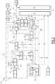
Figure 1 is a schematic block diagram of an installation according to a first embodiment of the invention, -
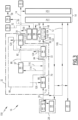
Figure 2 is a schematic block diagram of an installation according to a second embodiment of the invention, and -
Figure 3 is a schematic block diagram of an installation according to a third embodiment of the invention. - An
installation 10 according to a first embodiment of the invention will now be described with reference toFigure 1 . - The
installation 10 is adapted for deliveringelectricity 12 andheat 14. - In the example, the
installation 10 comprises aproduction facility 16 adapted for delivering saidelectricity 12 andheat 14, andlocal users 18 of said electricity and heat. Theinstallation 10 is advantageously adapted for exporting at least part of theelectricity 12 to a local, regional ornational grid 20. Theinstallation 10 is also advantageously adapted for delivering at least part of theheat 14 to one or severalexternal users 22, such as a district heating system. - The
installation 10 is for example also adapted to receive electricity from said local, regional ornational grid 20. - The split between the
production facility 16 and theusers 18 in theinstallation 10 is somewhat "artificial" here, as some of theusers 18 could be considered as part of theproduction facility 16 itself. In other words, at least some of thelocal users 18 are internal users of the production facility. - The
users 18 advantageously comprise one or several electricity user(s) 24 and one or several heat user(s) 26. One electricity user may also be a heat user. - For example, said one or several heat user(s) 26 comprise(s) one or several users among:
- a crude storage tank heating unit,
- a flare drums heating unit,
- a closed drain and open drain drums heating unit,
- a fire water storage tank, demineralization water storage tank, potable water storage tank,
- a steam tracing unit,
- export crude oil heaters,
- an amine regenerator,
- an LPG fractionation and condensate stabilization unit,
- a gas dehydration unit,
- a produced water treatment unit,
- an oil separation interstage heating unit,
- an electrostatic coalescer heater for oil and water separation, and
- any kind of process heat exchanger or heat loads.
- For example, said one or several electricity user(s) 24 comprise(s) one or several users among:
- pumps,
- compressors,
- refrigeration or cooling units,
- heat pumps, and
- lighting members.
- The
production facility 16 comprises anelectricity production unit 28 adapted for producingrenewable electricity 30, and a renewable energythermal assembly 32 comprising a hot fluid(s)generation system 33 adapted for producing one or several renewable hot fluid(s) 34 and renewable energy based steam 36. - By "renewable", it is meant that the considered energy is based on a natural renewable source, such as sun and wind. Such a source is rapidly renewable, and does not produce direct wastes, nor direct CO2 emissions.
- The
production facility 16 comprises aboiler unit 38 adapted for burningfuel 40 and producing at least fuel basedsteam 42, and a steam turbine unit 44 adapted for using the renewable energy based steam 36 and/or the fuel basedsteam 42 in order to produce steam basedelectricity 48. - Advantageously, the
installation 10 further comprises a source ofgreen fuel 50 adapted for supplyinggreen fuel 52 to theboiler unit 38, and acarbon capture unit 54 adapted for receivingexhausts 56 from the boiler unit and for producing a CO2rich fluid 58 intended to be transported, for example by pipelines or tanker ships, to along term storage 59, such as an aquifer. - The CO2
rich fluid 58 for example contains more than 80mol.%, preferably more than 90mol.%, of CO2. - The
installation 10 is configured for switching at least between three operation modes. - In a first operation mode of the three, the delivered
electricity 12 is produced by theelectricity production unit 28 alone, or by theelectricity production unit 28 and the steam turbine unit 44, or by the steam turbine unit 44 alone, the steam turbine unit 44 exclusively using the renewable energy based steam 36 and not the fuel basedsteam 42. The hot fluid(s)generation system 33 produces the deliveredheat 14. In the first operation mode, the deliveredelectricity 12 and the deliveredheat 14 are fully renewable. - In a second operation mode, the delivered
electricity 12 is produced by theelectricity production unit 28 alone, or by theelectricity production unit 28 and the steam turbine unit 44, or by the steam turbine unit 44 alone, the steam turbine unit 44 using the renewable energy based steam 36 exclusively, the fuel basedsteam 42 exclusively, or the renewable energy based steam 36 and the fuel basedsteam 42. The hot fluid(s)generation system 33 and theboiler unit 38 altogether produce the deliveredheat 14. In the second operation mode, the deliveredheat 14 is partially renewable, and the deliveredelectricity 12 is either renewable, or partially renewable, or non-renewable. - In a third operation mode, the
boiler unit 38 burns thefuel 40 and produces the deliveredheat 14 and the fuel basedsteam 42, and the steam turbine unit 44 uses the fuel basedsteam 42 to produce the delivered electricity. In the third operation mode, the deliveredelectricity 12 and the deliveredheat 14 are non-renewable, or just less renewable in case thegreen fuel 52 and/orcarbon capture unit 54 are advantageously used. - The first operation mode and the second operation mode are preferred compared with the third operation mode, and the first operation mode is preferred compared with the second operation mode.
- In variants, the
installation 10 is further configured to switch from these three operation modes to one or several other operation modes, which may be "intermediate" between the three operation modes, or different. - The
electricity production unit 28 for example comprisesphotovoltaic cells 60 and/or at least onewind turbine 62. - In the example, the
electricity production unit 28 advantageously comprises abattery electricity storage 64 adapted for storing electricity from thephotovoltaic cells 60 and/or the at least onewind turbine 62, and advantageously from the steam turbine unit 44 or from thegrid 20. - The
battery electricity storage 64 for example comprises lithium-ion batteries. - Apart from the hot fluid(s)
generation system 33, the renewable energythermal assembly 32 comprises a firstthermal storage 66 unit adapted for storingthermal energy 67, and anelectrical heater unit 68 electrically connected to theelectricity production unit 28 and adapted for producing electricity basedthermal energy 70 using at least onepart 72 of theelectricity 30 produced by theelectricity production unit 28. - In the example, the renewable energy
thermal assembly 32 further comprises a solarthermal unit 74 adapted for producing solar basedthermal energy 76. - In the first embodiment, the solar
thermal unit 74 is configured for delivering the solar basedthermal energy 76 to the firstthermal storage 66, and theelectrical heater unit 68 is configured for delivering the electricity basedthermal energy 70 to the firstthermal storage unit 66. In other words, the solarthermal unit 74 and theelectrical heater unit 68 are mounted in parallel to each other. - For example, the solar
thermal unit 74, theelectrical heater unit 68 and the firstthermal storage unit 66 are configured for producinghot flows - The
electrical unit 68 for example comprises at least one electrical heater (not represented). - The solar
thermal unit 74 is known in itself and will not be described in detail. The solarthermal unit 74 for example comprises parabolic trough collectors (PTC technology) or a solar power tower (SPT technology), which are not shown. - The first
thermal storage unit 66 for example comprisesmolten salts 86, for example a binary salt with 40wt.% KNO3 and 60wt.% NaNOs . Such a thermal storage unit is known in itself and will not be described in detail. - The first
thermal storage unit 66 for example comprises afirst heat exchanger 88 adapted for recovering the solar basedthermal energy 76, and a firstthermal storage 90 adapted for storing thermal energy. - The
thermal storage unit 66 may further comprise one or several of the following elements (not represented): - a concentration system using water and steam for example at 250°C,
- hot oil, for example at 393°C,
- molten salts, for example up to 750°C,
- thermocline with solid materials.
- The hot fluid(s)
generation system 33 is adapted for using internal renewable energy generated or present within the renewable energythermal assembly 32 in order to produce said one or several hot fluid(s) 34 and the renewable energy based steam 36. - The internal renewable energy includes the electricity based
thermal energy 70, the storedthermal energy 67, and, in the example, the solar basedthermal energy 76 coming from the solarthermal unit 74. - For example, the hot fluid(s)
generation system 33 is configured for exclusively using the storedthermal energy 67, the electricity basedthermal energy 70, and the solarthermal energy 76 being received in the firstthermal storage unit 66 before being used by the hot fluid(s)generation system 33. This provides stability in the supply of heat (thermal energy) to the hot fluid(s)generation system 33. - The hot fluid(s)
generation system 33 for example comprises asecond heat exchanger 92 adapted for producing said one or several hot fluid(s) 34 using thehot fluid 82 from the firstthermal storage unit 66. The hot fluid(s)generation system 33 for example comprises athird heat exchanger 94 adapted for producing the renewable energy based steam 36 using theflow 84 from the firstthermal storage unit 66. - The
boiler unit 38 for example comprises afirst boiler 96 and asecond boiler 98. - As variants (not shown), the
boiler unit 38 comprises one boiler, or more than two boilers. - The
boiler unit 38 is adapted to burn thefuel 40, which is a hydrocarbon one, and/or thegreen fuel 52. - Advantageously, the
boiler unit 38, and theinstallation 10, are deprived of any gas turbine. - The
first boiler 96 is for example adapted for producing one or severalhot fluids 100 intended to constitute at least part of the deliveredheat 14. - The
second boiler 98 is for example adapted for producing the fuel basedsteam 42. - The steam turbine unit 44 comprises at least one
steam turbine 102 and at least oneelectricity generator 104. - As variants (not shown), the steam turbine unit 44 may comprise more than one steam turbine and/or more than one electricity generator.
- The steam turbine unit 44 is designed for expanding a nominal amount of steam. Advantageously, in the first operation mode, the hot fluid(s)
generation system 33 is configured for continuously producing the renewable energy based steam 36, at a flowrate equal to or larger than a minimal turn down of the steam turbine unit 44, for example 10% of said nominal amount of steam, and the steam turbine unit 44 uses the renewable energy based steam 36 in order to produce thepart 48 of the deliveredelectricity 12. This allows quick ramp-up of the steam turbine unit 44, if more electricity is needed from the steam turbine unit 44. - The operation of the
installation 10 will now be described and illustrates a process according to the invention. - The
installation 10 delivers saidelectricity 12 for theusers 18 and advantageously thegrid 20, or may sometimes receive electricity from thegrid 20. Theinstallation 10 also delivers theheat 14 to theusers 18, and advantageously to theexternal users 22. - Depending in particular on the weather conditions, especially the amount of sun and/or wind, and on the availability of the
electricity production unit 28 and of the solarthermal unit 74, theinstallation 10 is switched between at least the first operation mode, the second operation mode and the third operational mode. - In the first operation mode, the hot fluid(s)
generation system 33 produces the deliveredheat 14. - The delivered
electricity 12 may be entirely produced by theelectricity production unit 28, for example when the latter can produce enough and the steam turbine unit 44 is idle. - The delivered
electricity 12 may be produced by theelectricity production unit 28 and the steam turbine unit 44, for example in order to be ready for a quick ramp-up of the steam turbine unit 44, or because theelectricity production unit 28 cannot produce enough electricity. In this case, theelectricity production unit 28 produces apart 106 of the deliveredelectricity 12 and the steam turbine unit 44 produces thepart 48, using the renewable energy based steam 36 produced by hot fluid(s)generation system 33. - In case there is excess production of the
electricity 30, at least one part of it may be stored in thebattery electricity storage 64. Possibly, thepart 72 of the producedelectricity 30 is sent to theelectrical heater unit 68. - If the
electricity production unit 28 is idle, the deliveredelectricity 12 may be produced by the steam turbine unit 44 using the renewable energy based steam 36. - In any case, in the first operation mode, the
boiler unit 38 is idle. - The solar
thermal unit 74, when it works, produces the solar basedthermal energy 76. - The
first heat exchanger 88 recovers the solar basedthermal energy 76. For example, thefirst heat exchanger 88 performs a heat exchange between theflow 78 coming from the solarthermal unit 74, for example at 390°C, and aflow 108 for example at 300°C, in order to obtain aflow 110, for example at 310°C, which is returned to the solarthermal unit 74, and aflow 112, for example at 380°C. Theflow 78 and theflow 110 are for example hot oil. Theflow 108 and theflow 112 are for example molten salts. This allows storing the solarthermal energy 76 in the firstthermal storage unit 66 or, as a variant, passing it or some of it directly to the hot fluid(s)generation system 33. - The first
thermal storage 90 stores part of the internal renewable energy. The firstthermal storage 90 may receive aflow 114, for example at 380°C, in order to store heat. The firstthermal storage 90 may produce aflow 116, for example at 380°C. The flows 114, 116 are for example molten salts. - The hot fluid(s)
generation system 33 uses the internal renewable energy and produce said one or several hot fluid(s) 34. For example, thesecond heat exchanger 92 uses theflow 82 coming from the firstthermal storage unit 66, for example at 380°C, in order to produce said one or several hot fluid(s) 34, and aflow 120 returned to the firstthermal storage unit 66, for example at 300°C. The flows 82, 120 are for example molten salts. - In a particular embodiment, the hot fluid(s)
generation system 33 also produces a flow offluid 122, the steam turbine unit 44 being heated (kept at a certain temperature) by the flow offluid 122 without expanding the flow offluid 122. This allows keeping the steam turbine unit 44 in warm stand-by. - Optionally, the steam turbine unit 44 runs at its minimum load, using the renewable energy based steam 36 and produces the
part 48 of the deliveredelectricity 12. This allows a quick ramp-up of the steam turbine unit 44. - If more electricity needs to be delivered, or there is not enough renewable electricity produced, as a first priority the electricity stored in the
battery electricity storage 64 is used to supply theusers 18. As a second priority, the steam turbine unit 44 is run at a higher load, using the renewable energy based steam 36. - The
battery electricity storage 64 may also store electricity in order to allow a ramp-up or a ramp-down of the steam turbine unit 44. - The renewable energy based steam 36 is produced by the
third heat exchanger 94. For example, thethird heat exchanger 94 receives theflow 84, for example at 380°C coming from the firstthermal storage unit 66, in order to produce the renewable energy based steam 36, and aflow 124 returned to the firstthermal storage unit 66, for example at 300°C. The flows 84, 124 are for example molten salts. - When the
electricity 30 produced by theelectricity production unit 28 is in excess, the excess electricity is advantageously used to charge thebattery electricity storage 64 as a first priority, and thepart 72 is sent to theelectrical heater unit 68 as a second priority in order to provide the electricity basedthermal energy 70 to the firstthermal storage unit 66. - If the solar
thermal unit 74 does not produce enough solar basedthermal energy 76 to cover what the hot fluid(s)generation system 33 needs, the renewable energythermal assembly 32 uses the storedthermal energy 67 or the electricity basedthermal energy 70. - The
thermal storage unit 66 and the batteryelectricity storage unit 64 are advantageously used to manage intermittency or for peak shifting supply, or for optimizing the efficiency of the electricity and heat delivery. - The battery
electricity storage unit 64 is advantageously used for short term intermittency. For example when there are clouds, the batteryelectricity storage unit 64 can compensate for the missing electricity production. - The
thermal storage unit 66 is advantageously used for long term intermittency, such as the night/day one. - When the
other part 72 of theelectricity 30 is sent to theelectrical heater unit 68, the latter uses saidother part 72 and heats aflow 126 coming from the firstthermal storage unit 66, for example at 300°C, in order to obtain theflow 80 which is returned to the firstthermal storage unit 66, for example at 380°C. The flows 80, 126 are for example molten salts. This allows storing the electricity basedthermal energy 70 in the firstthermal storage unit 66 or, as a variant, passing it or some of it directly to the hot fluid(s)generation system 33. - In the second operation mode, the hot fluid(s)
generation system 33 and theboiler unit 38 produce the deliveredheat 14. The hot fluid(s)generation system 33 produces said one or several hot fluid(s), forming a first part of the deliveredheat 14, in the same manner as in the first operation mode. Theboiler unit 38 produces said one or severalhot fluids 100, forming a second part of the deliveredheat 14. For example, thefirst boiler 96 burns thefuel 40, or advantageously thegreen fuel 52, in order to produce said second part. - The delivered
electricity 12 is produced in the same manner as in the first operation mode, except that the steam turbine unit 44, if it runs, uses the renewable energy based steam 36 and/or the fuel basedsteam 42, the latter being less preferred. In some cases where there is not enough internal renewable energy, the steam turbine unit 44 may use steam that is for example partially or totally produced by thesecond boiler 98 using thefuel 40, or preferably thegreen fuel 52. - The
exhausts 56 from theboiler unit 38 are preferably received and treated by thecarbon capture unit 54. - In any case, in the second operation mode, the
boiler unit 38 is used at least for producing the second part of the deliveredheat 14, and possibly for producing the fuel basedsteam 42 processed by the steam turbine unit 44. - In the third operation mode, as already mentioned, the
boiler unit 38 burns thefuel 40, or preferably thegreen fuel 52, and produces the deliveredheat 14 and the fuel basedsteam 42. The steam turbine unit 44 uses the fuel basedsteam 42 to produce thepart 48 which forms all of the deliveredelectricity 12. - Like in in the second operation mode, the
exhausts 56 from theboiler unit 38 are preferably received and treated by thecarbon capture unit 54. - An
installation 130 according to a second embodiment of the invention will now be described with reference toFigure 2 . - The
installation 130 is analogous to theinstallation 10 represented inFigure 1 . Similar elements bear the same numeral references and will not be described again. Only the differences will be described in detail hereafter. - The renewable energy
thermal assembly 32 further comprises a secondthermal storage unit 132 adapted for storing the solar basedthermal energy 76. - The second
thermal storage unit 132 comprises the first heat exchanger 88 (which is not any more in the first thermal storage unit 66) and asecond storage 134. - The second
thermal storage unit 132 is configured for delivering the stored solar basedthermal energy 76 to the electrical heater unit, andelectrical heater unit 68 is configured for delivering the electricity basedthermal energy 70 to the firstthermal storage unit 66. In other words, the solarthermal unit 74 and theelectrical heater unit 68 are mounted in series. - The second
thermal storage unit 132 is adapted to work as a buffer between the solarthermal unit 74 and theelectrical heater unit 68 in order to help managing the production of the solarthermal energy 76 and of the electricity basedthermal energy 70. - The second
thermal storage unit 132 is configured for producing aflow 136 having a temperature for example comprised between 350 and 420°C, and theelectrical heater unit 68 and the firstthermal storage unit 66 are configured for producing theflows - The
installation 130 operates in a manner analogous to that of theinstallation 10 with the following differences. - When the solar
thermal unit 74 runs, thefirst heat exchanger 88 recovers the solar basedthermal energy 76. For example, thefirst heat exchanger 88 performs a heat exchange between thefirst flow 78 coming from the solarthermal unit 74, for example at 390°C, and theflow 108, for example still at 300°C, in order to obtain theflow 110, for example at 310°C, which is returned to the solarthermal unit 74, and theflow 112, for example at 380°C. - The
flow 112 is not returned to the firstthermal storage unit 66, but received by the secondthermal storage 134, where thermal energy can be stored, or, as a variant, directly passed to theelectrical heater unit 68. - If the
part 72 of the producedelectricity 30 is sent to theelectrical heater unit 68, the latter uses saidpart 72 in order to heat theflow 136 coming from the secondthermal storage unit 132, for example at 380°C, in order to obtain theflow 80 sent to the first thermal storage unit, for example at 565°C. Theflow 136 is for example molten salts. - The
flows - An
installation 150 according to a third embodiment of the invention will now be described with reference toFigure 3 . - The
installation 150 is analogous to theinstallation 10 represented inFigure 1 . Similar elements bear the same numeral references and will not be described again. Only the differences will be described in detail hereafter. - The
installation 150 does not comprise the solarthermal unit 74 and thefirst heat exchanger 88 shown inFigure 1 . As a consequence, the internal renewable energy (generated or present with the renewable energy thermal assembly 32) includes the electricity based thermal energy, the stored thermal energy, and no solar thermal energy. - The
installation 150 operates in a manner analogous to that of theinstallation 10 with the following differences. - Depending in particular on the weather conditions, especially the amount of sun and/or wind, and on the availability of the
electricity production unit 28, theinstallation 150 is switched between at least the first operation mode, the second operation mode and the third operational mode. - The
flows - The following table 1 defines a Reference case (not according to the invention) and four examples (according to the invention) and provides installed capacities of the units:
Table 1 - Definition of reference and examples Case Definition Non renewable Units Electricity Production Unit 28Renewable Energy Thermal Assembly 32Boiler Unit 38Gas Turbine WHRU Photovoltaic Cells 60Battery Electricity Storage 64Solar Thermal Unit 74Thermal Storage Unit 66Electrical Heater Unit 68MWth MWe MWth GWp MWh MWth GWhth MW Reference Gas turbine, waste heat recovery unit (WHRU), and gas boiler 65 285 140 N/A N/A N/A N/A N/A Example 1 Installation 130630 N/A N/A 1.0 170 737 6.2 600 Example 2 Installation 150630 N/A N/A 1.4 170 0 5.3 889 Example 3 Installation 130630 N/A N/A 1.0 188 2 319 8.3 531 Example 4 Installation 150630 N/A N/A 2.0 170 0 7.5 1 183 - In each case 170 MWe of
electricity 12 and 205 MWth ofheat 14 are provided to the users. Examples 1 and 3 are based on theinstallation 130 described above with thermal energy storage with temperature at 380°C. Examples 2 and 4 are based on theinstallation 150 described above with thermal energy storage with temperature at 565°C. - The following table 2 shows how long the examples could run in the first, second and third operation modes in time percentages:
Table 2 - time percentages in the first, second and third operation modes Case Operation modes First Second Third % time % time % time Reference 0% 0% 100% Example 1 58% 21% 21% Example 2 51% 30% 19% Example 3 79% 11% 11% Example 4 71% 22% 7% - The following table 3 shows the footprints and performances of the examples:
Table 3 - Footprints and performance Case Footprints CO2 Photovoltaic Cells 60Solar Thermal Unit 74Total emissions reduction abatement efficiency ha ha ha ktCO2/yr % ktCO2/yr/ha Reference N/A N/A N/A 990 N/A N/A Example 1 1 680 1 123 2 821 396 60% 0.21 Example 2 2 407 0 2 423 396 60% 0.25 Example 3 1 680 3 536 5 239 198 80% 0.15 Example 4 3 362 0 3 382 198 80% 0.23 - Examples 1 and 2 allow a 60% reduction in CO2 emissions, with moderate footprints. Examples 3 and 4 allow a 80% reduction in CO2 emissions, with comparatively larger footprints.
- Thanks to the above described features, the
installations electricity 12 and theheat 14 without burning fuel, and in the second operation mode when there is not enough renewable energy. In particular, the firstthermal storage unit 66 allows storing thermal energy when renewable energy is produced in excess, and provides a smooth supply of heat even when the renewable energy production decreases or stops, or is simply irregular. Theelectrical heater unit 68 allows converting some of the producedelectricity 30 into the electricity basedthermal energy 70, when the produced electricity is in relative excess compared to the optional production of solarthermal energy 76. Conversely, the steam turbine unit 44 allows converting the internal renewable energy into theelectricity part 48 when there is a lack of producedelectricity 30. This provides theinstallations - The
installations electricity 12 and theheat 14 with an increased level of decarbonization compared to the prior art. The achieved level of decarbonization is above 50% and may go up to 80%. - Being advantageously deprived of any gas turbine, the
boiler unit 38 can run at a very minimal load or being idle. Theboiler unit 38 may advantageously be kept in warm stand-by or at a minimum load allowing a quick ramp-up. - Any excess in the produced
electricity 30 is advantageously stored first in the optionalbattery electricity storage 64, and secondly converted in thermal energy when thebattery electricity storage 64 is full. - The optional use of the
green fuel 52 and thecarbon capture unit 54 may further improve the level of decarbonization. - Besides, the availability of the
installations boiler unit 38.
Claims (15)
- An installation (10; 130; 150) for delivering electricity (12) and heat (14), comprising:- an electricity production unit (28), the electricity production unit (28) comprising photovoltaic cells (60) and/or at least one wind turbine (62), and being adapted for producing electricity (30),- a renewable energy thermal assembly (32) comprising:. a first thermal storage unit (66) adapted for storing thermal energy,. an electrical heater unit (68) electrically connected to the electricity production unit (28) and adapted for producing electricity based thermal energy (70) using at least a part (72) of the electricity (30) produced by the electricity production unit (28), and. a hot fluid(s) generation system (33) adapted for using internal renewable energy generated or present within the renewable energy thermal assembly (32) in order to produce one or several hot fluid(s) (34) and renewable energy based steam (36),- a boiler unit (38) comprising at least one boiler (96) and adapted for burning fuel (40) and producing fuel based steam (42), and- a steam turbine unit (44) comprising at least one steam turbine (102) and at least one electricity generator (104),the installation (10; 130; 150) being configured for switching at least between:- a first operation mode, in which the delivered electricity (12) is produced by the electricity production unit (28), or by the electricity production unit (28) and the steam turbine unit (44), or by the steam turbine unit (44), the steam turbine unit (44) using the renewable energy based steam (36), and in which the hot fluid(s) generation system (33) produces the delivered heat (14),- a second operation mode, in which the delivered electricity (12) is produced by the electricity production unit (28), or by the electricity production unit (28) and the steam turbine unit (44), or by the steam turbine unit (44), the steam turbine unit (44) using the renewable energy based steam (36) and/or the fuel based steam (42), and in which the hot fluid(s) generation system (33) and the boiler unit (38) produce the delivered heat (14), and- a third operation mode, in which the boiler unit (44) burns the fuel (40) and produces the delivered heat (14) and the fuel based steam (42), and the steam turbine unit (44) uses the fuel based steam (42) to produce the delivered electricity (14).
- The installation (10; 130; 150) according to claim 1, wherein the hot fluid(s) generation system (33) is configured for exclusively using thermal energy coming from the first thermal storage unit (66), the electricity based thermal energy (70) being entirely received by the first thermal storage unit (66).
- The installation 10; 130; 150) according to claim 1 or 2, wherein the electricity production unit (28) comprises a battery electricity storage (64) adapted for storing electricity.
- The installation 10; 130; 150) according to any one of claims 1 to 3, further comprising a source of green fuel (50) adapted for supplying green fuel (52) to the boiler unit (38).
- The installation 10; 130; 150) according to any one of claims 1 to 4, further comprising a carbon capture unit (54) configured for receiving exhausts (56) from the boiler unit (38) and for producing a CO2 rich fluid (58) intended to be transported to a long term storage (59).
- The installation (10; 130; 150) according to any one of claims 1 to 5, wherein the hot fluid(s) generation system (33), at least in the first operation mode, continuously produces the renewable energy based steam (36) at a flowrate equal to or larger than a minimum turn down of the steam turbine unit (44), and the steam turbine unit (44) uses the renewable energy based steam (36) in order to produce a part (48) of the delivered electricity (14).
- The installation (10; 130; 150) according to any one of claims 1 to 6, wherein, in the first operation mode, the hot fluid(s) generation system (33) produces a flow of fluid (122), the steam turbine unit (44) being heated by the flow of fluid (122) without expanding the flow of fluid (122).
- The installation (10; 130; 150) according to any one of claims 1 to 7, wherein the first thermal storage unit (66) comprises molten salts (86).
- The installation (10; 130) according to any one of claims 1 to 7, wherein the renewable energy thermal assembly (32) comprises a solar thermal unit (74) adapted for producing solar based thermal energy (76), said internal renewable energy including the stored thermal energy, the solar based thermal energy and the electricity based thermal energy.
- The installation (10) according to claim 9, wherein the solar thermal unit (74) is configured for delivering the solar based thermal energy (76) to the first thermal storage unit (66), and the electrical heater unit (68) is configured for delivering the electricity based thermal energy (76) to the first thermal storage unit (66).
- The installation (10) according to claim 9 or 10, wherein the solar thermal unit (74), the electrical heater unit (68) and the first thermal storage unit (66) are configured for producing flows (78, 80, 82, 84), each of said flows having a temperature comprised between 350°C and 420°C.
- The installation (130) according to claim 9, wherein the renewable energy thermal assembly (32) comprises a second thermal storage unit (132) adapted for storing the solar based thermal energy (76).
- The installation (130) according to claim 12, wherein the second thermal storage unit (132) is configured for delivering the stored solar based thermal energy (76) to the electrical heater unit (68), and electrical heater unit (68) is configured for delivering the electricity based thermal energy (70) to the first thermal storage unit (66).
- The installation (130) according to claim 12 or 13, wherein the second thermal storage unit (132) is configured for producing a flow (78) having a temperature comprised between 350 and 420°C, and the electrical heater unit (68) and the first thermal storage unit (66) are configured for producing flows (80, 82, 84), each of said flows (80, 82, 84) having a temperature comprised between 500°C and 750°C.
- A process for delivering electricity and heat, the process comprising:- obtaining an installation (10; 130; 150) as described by any of claims 1 to 14, and- switching at least between:- a first operation mode, in which the delivered electricity (12) is produced by the electricity production unit (28), or by the electricity production unit (28) and the steam turbine unit (44), or by the steam turbine unit (44), the steam turbine unit (44) using the renewable energy based steam (36), and in which the hot fluid(s) generation system (33) produces the delivered heat (14),- a second operation mode, in which the delivered electricity (12) is produced by the electricity production unit (28), or by the electricity production unit (28) and the steam turbine unit (44), or by the steam turbine unit (44), the steam turbine unit (44) using the renewable energy based steam (36) and/or the fuel based steam (42), and in which the hot fluid(s) generation system (33) and the boiler unit (38) produce the delivered heat (14), and- a third operation mode, in which the boiler unit (34) burns the fuel (40) and produces the delivered heat (14) and the fuel based steam (42), and the steam turbine unit (44) uses the fuel based steam (42) to produce the delivered electricity (14).
Priority Applications (2)
| Application Number | Priority Date | Filing Date | Title |
|---|---|---|---|
| EP23307016.8A EP4560116A1 (en) | 2023-11-21 | 2023-11-21 | Installation for delivering highly decarbonized electricity and heat |
| PCT/EP2024/082994 WO2025109004A1 (en) | 2023-11-21 | 2024-11-20 | Installation for delivering highly decarbonized electricity and heat |
Applications Claiming Priority (1)
| Application Number | Priority Date | Filing Date | Title |
|---|---|---|---|
| EP23307016.8A EP4560116A1 (en) | 2023-11-21 | 2023-11-21 | Installation for delivering highly decarbonized electricity and heat |
Publications (1)
| Publication Number | Publication Date |
|---|---|
| EP4560116A1 true EP4560116A1 (en) | 2025-05-28 |
Family
ID=89119549
Family Applications (1)
| Application Number | Title | Priority Date | Filing Date |
|---|---|---|---|
| EP23307016.8A Pending EP4560116A1 (en) | 2023-11-21 | 2023-11-21 | Installation for delivering highly decarbonized electricity and heat |
Country Status (2)
| Country | Link |
|---|---|
| EP (1) | EP4560116A1 (en) |
| WO (1) | WO2025109004A1 (en) |
Citations (8)
| Publication number | Priority date | Publication date | Assignee | Title |
|---|---|---|---|---|
| EP3081770A1 (en) * | 2015-04-17 | 2016-10-19 | Siemens Aktiengesellschaft | Energy storage system and method |
| CN113669039A (en) * | 2021-09-13 | 2021-11-19 | 中国石油大学(华东) | Steam-assisted heavy oil thermal recovery system |
| US20220149697A1 (en) * | 2018-12-18 | 2022-05-12 | Nicholas Pan. Pittas | Automatic wins and photovoltaic energy storage system for uninterrupted electricity generation and energy autonomy |
| US11359521B2 (en) * | 2015-11-05 | 2022-06-14 | William M. Conlon | Dispatchable storage combined cycle power plants |
| US20220275755A1 (en) * | 2019-07-19 | 2022-09-01 | Siemens Energy Global GmbH & Co. KG | Gas turbine comprising thermal energy store, method for operating same, and method for modifying same |
| US20230052951A1 (en) * | 2020-01-29 | 2023-02-16 | Siemens Energy Global GmbH & Co. KG | System comprising thermal accumulator, method for operating same, and method for modifying same |
| US20230243338A1 (en) * | 2020-06-16 | 2023-08-03 | Siemens Gamesa Renewable Energy Innovation & Technology S.L. | Wind power plant with power conversion system |
| US20230296034A1 (en) * | 2020-11-30 | 2023-09-21 | Rondo Energy, Inc. | Thermal energy storage system coupled with thermal power cycle systems |
-
2023
- 2023-11-21 EP EP23307016.8A patent/EP4560116A1/en active Pending
-
2024
- 2024-11-20 WO PCT/EP2024/082994 patent/WO2025109004A1/en active Pending
Patent Citations (8)
| Publication number | Priority date | Publication date | Assignee | Title |
|---|---|---|---|---|
| EP3081770A1 (en) * | 2015-04-17 | 2016-10-19 | Siemens Aktiengesellschaft | Energy storage system and method |
| US11359521B2 (en) * | 2015-11-05 | 2022-06-14 | William M. Conlon | Dispatchable storage combined cycle power plants |
| US20220149697A1 (en) * | 2018-12-18 | 2022-05-12 | Nicholas Pan. Pittas | Automatic wins and photovoltaic energy storage system for uninterrupted electricity generation and energy autonomy |
| US20220275755A1 (en) * | 2019-07-19 | 2022-09-01 | Siemens Energy Global GmbH & Co. KG | Gas turbine comprising thermal energy store, method for operating same, and method for modifying same |
| US20230052951A1 (en) * | 2020-01-29 | 2023-02-16 | Siemens Energy Global GmbH & Co. KG | System comprising thermal accumulator, method for operating same, and method for modifying same |
| US20230243338A1 (en) * | 2020-06-16 | 2023-08-03 | Siemens Gamesa Renewable Energy Innovation & Technology S.L. | Wind power plant with power conversion system |
| US20230296034A1 (en) * | 2020-11-30 | 2023-09-21 | Rondo Energy, Inc. | Thermal energy storage system coupled with thermal power cycle systems |
| CN113669039A (en) * | 2021-09-13 | 2021-11-19 | 中国石油大学(华东) | Steam-assisted heavy oil thermal recovery system |
Also Published As
| Publication number | Publication date |
|---|---|
| WO2025109004A1 (en) | 2025-05-30 |
Similar Documents
| Publication | Publication Date | Title |
|---|---|---|
| US10340693B2 (en) | Systems and methods for generating energy using a hydrogen cycle | |
| CN102200103B (en) | Integrated solar combined-cycle power generation plant and How It Works thereof | |
| KR100849578B1 (en) | High efficiency energy saving heating system with combined heat source | |
| CN114386263B (en) | A mid- to long-term planning approach for an integrated energy system considering carbon reduction constraints and hydrogen energy | |
| US6536215B1 (en) | Method for optimally operating co-generation of electricity and heat and optimally operating district heating power plant | |
| CN102926955A (en) | Independently distributed comprehensive utilization system for renewable energy sources | |
| CN112963212B (en) | Low-carbon energy utilization system of oilfield steam and power cogeneration | |
| US12196499B2 (en) | Energy storage and retrieval system comprising a regenerator and an electrical machine coupled to a compressor and an expander | |
| CN115234965B (en) | Regional heating system and method with coordinated source network and charge storage | |
| CN114844102A (en) | Integrated energy system suitable for thermal power plant, operation method and storage medium | |
| CN117588790A (en) | Light-fire complementary wide-load adjustable high back-pressure heating unit | |
| EP4377558B1 (en) | Installation for producing electricity and heat, comprising a gas turbine unit | |
| CN217903155U (en) | Combined cycle combined cooling heating and power system integrating fuel cell and solar energy | |
| WO2025109004A1 (en) | Installation for delivering highly decarbonized electricity and heat | |
| RU157771U1 (en) | GAS TURBINE INSTALLATION | |
| CN210624681U (en) | Cold, heat, electricity trigeminy supplies new forms of energy storage energy supply and peak shaving system | |
| CN209639302U (en) | A combined cooling, heating and power supply system for households combining wind and gas | |
| CN110173371B (en) | Distributed energy system of natural gas internal combustion engine with high-efficiency operation and operation method | |
| CN114498693B (en) | A device system and method based on multi-energy storage in the steel industry | |
| Zhao et al. | Capacity optimization allocation of electrothermal hydrogen integrated energy system considering start-stop characteristics of multiple electrolyzers | |
| CN114719322B (en) | Mining area multifunctional complementary clean heating system and application method thereof | |
| CN119353814B (en) | Low-carbon running-considered ground source heat pump distributed energy system running strategy | |
| CN224191645U (en) | A low-carbon baseload power source that couples new energy sources with gas electricity | |
| CN215370046U (en) | Gas turbine combined heat and power supply device | |
| Iyanova et al. | Innovative Technologies for Utility Power System |
Legal Events
| Date | Code | Title | Description |
|---|---|---|---|
| PUAI | Public reference made under article 153(3) epc to a published international application that has entered the european phase |
Free format text: ORIGINAL CODE: 0009012 |
|
| STAA | Information on the status of an ep patent application or granted ep patent |
Free format text: STATUS: THE APPLICATION HAS BEEN PUBLISHED |
|
| AK | Designated contracting states |
Kind code of ref document: A1 Designated state(s): AL AT BE BG CH CY CZ DE DK EE ES FI FR GB GR HR HU IE IS IT LI LT LU LV MC ME MK MT NL NO PL PT RO RS SE SI SK SM TR |
|
| STAA | Information on the status of an ep patent application or granted ep patent |
Free format text: STATUS: REQUEST FOR EXAMINATION WAS MADE |
|
| 17P | Request for examination filed |
Effective date: 20251113 |