EP4560089A2 - Bodenplatte zur bildung eines bodenbelags - Google Patents
Bodenplatte zur bildung eines bodenbelags Download PDFInfo
- Publication number
- EP4560089A2 EP4560089A2 EP25169724.9A EP25169724A EP4560089A2 EP 4560089 A2 EP4560089 A2 EP 4560089A2 EP 25169724 A EP25169724 A EP 25169724A EP 4560089 A2 EP4560089 A2 EP 4560089A2
- Authority
- EP
- European Patent Office
- Prior art keywords
- floor panel
- directed
- locking
- pair
- downward
- Prior art date
- Legal status (The legal status is an assumption and is not a legal conclusion. Google has not performed a legal analysis and makes no representation as to the accuracy of the status listed.)
- Pending
Links
Images


Classifications
-
- E—FIXED CONSTRUCTIONS
- E04—BUILDING
- E04F—FINISHING WORK ON BUILDINGS, e.g. STAIRS, FLOORS
- E04F15/00—Flooring
- E04F15/02—Flooring or floor layers composed of a number of similar elements
-
- E—FIXED CONSTRUCTIONS
- E04—BUILDING
- E04F—FINISHING WORK ON BUILDINGS, e.g. STAIRS, FLOORS
- E04F15/00—Flooring
- E04F15/02—Flooring or floor layers composed of a number of similar elements
- E04F15/02005—Construction of joints, e.g. dividing strips
- E04F15/02033—Joints with beveled or recessed upper edges
-
- E—FIXED CONSTRUCTIONS
- E04—BUILDING
- E04F—FINISHING WORK ON BUILDINGS, e.g. STAIRS, FLOORS
- E04F15/00—Flooring
- E04F15/02—Flooring or floor layers composed of a number of similar elements
- E04F15/02038—Flooring or floor layers composed of a number of similar elements characterised by tongue and groove connections between neighbouring flooring elements
-
- E—FIXED CONSTRUCTIONS
- E04—BUILDING
- E04F—FINISHING WORK ON BUILDINGS, e.g. STAIRS, FLOORS
- E04F15/00—Flooring
- E04F15/02—Flooring or floor layers composed of a number of similar elements
- E04F15/10—Flooring or floor layers composed of a number of similar elements of other materials, e.g. fibrous or chipped materials, organic plastics, magnesite tiles, hardboard, or with a top layer of other materials
- E04F15/107—Flooring or floor layers composed of a number of similar elements of other materials, e.g. fibrous or chipped materials, organic plastics, magnesite tiles, hardboard, or with a top layer of other materials composed of several layers, e.g. sandwich panels
-
- E—FIXED CONSTRUCTIONS
- E04—BUILDING
- E04F—FINISHING WORK ON BUILDINGS, e.g. STAIRS, FLOORS
- E04F2201/00—Joining sheets or plates or panels
- E04F2201/01—Joining sheets, plates or panels with edges in abutting relationship
- E04F2201/0138—Joining sheets, plates or panels with edges in abutting relationship by moving the sheets, plates or panels perpendicular to the main plane
- E04F2201/0146—Joining sheets, plates or panels with edges in abutting relationship by moving the sheets, plates or panels perpendicular to the main plane with snap action of the edge connectors
-
- E—FIXED CONSTRUCTIONS
- E04—BUILDING
- E04F—FINISHING WORK ON BUILDINGS, e.g. STAIRS, FLOORS
- E04F2201/00—Joining sheets or plates or panels
- E04F2201/01—Joining sheets, plates or panels with edges in abutting relationship
- E04F2201/0153—Joining sheets, plates or panels with edges in abutting relationship by rotating the sheets, plates or panels around an axis which is parallel to the abutting edges, possibly combined with a sliding movement
-
- E—FIXED CONSTRUCTIONS
- E04—BUILDING
- E04F—FINISHING WORK ON BUILDINGS, e.g. STAIRS, FLOORS
- E04F2201/00—Joining sheets or plates or panels
- E04F2201/02—Non-undercut connections, e.g. tongue and groove connections
- E04F2201/023—Non-undercut connections, e.g. tongue and groove connections with a continuous tongue or groove
-
- E—FIXED CONSTRUCTIONS
- E04—BUILDING
- E04F—FINISHING WORK ON BUILDINGS, e.g. STAIRS, FLOORS
- E04F2201/00—Joining sheets or plates or panels
- E04F2201/04—Other details of tongues or grooves
-
- E—FIXED CONSTRUCTIONS
- E04—BUILDING
- E04F—FINISHING WORK ON BUILDINGS, e.g. STAIRS, FLOORS
- E04F2201/00—Joining sheets or plates or panels
- E04F2201/04—Other details of tongues or grooves
- E04F2201/041—Tongues or grooves with slits or cuts for expansion or flexibility
-
- E—FIXED CONSTRUCTIONS
- E04—BUILDING
- E04F—FINISHING WORK ON BUILDINGS, e.g. STAIRS, FLOORS
- E04F2201/00—Joining sheets or plates or panels
- E04F2201/04—Other details of tongues or grooves
- E04F2201/042—Other details of tongues or grooves with grooves positioned on the rear-side of the panel
-
- E—FIXED CONSTRUCTIONS
- E04—BUILDING
- E04F—FINISHING WORK ON BUILDINGS, e.g. STAIRS, FLOORS
- E04F2201/00—Joining sheets or plates or panels
- E04F2201/04—Other details of tongues or grooves
- E04F2201/043—Other details of tongues or grooves with tongues and grooves being formed by projecting or recessed parts of the panel layers
Definitions
- This invention relates to a floor panel for forming a floor covering, more particularly for forming a floor covering which can be installed on an underlying surface. More particularly, the invention relates to floor panels which can be coupled to each other by means of mechanical coupling parts.
- the aim of the invention is that a floor covering of such floor panels can be installed easily, however, that simultaneously also sufficient strength is obtained in the floor covering, more particularly sufficiently strong connections can be realized among the floor panels, such in combination with production techniques which keep the production costs limited.
- the invention relates to floor panels which can be installed by means of the so-called fold-down technique, such in order to be able to fulfill the targeted requirement of a simple installation.
- a fact herein is that two of the edges, in the case of oblong floor panels mostly the short edges, must be able to be joined to each other by means of a downward movement, bringing about a vertical locking.
- a good vertical locking can be realized by means of separate elastic locking strips.
- An example of such approach is disclosed in WO2017/068523 .
- one-piece or substantially one-piece coupling profiles can be used for the edges of floor panels to be joined by a downward movement thereby creating a vertical locking.
- Such approach is disclosed in WO2017/115202 , WO2018/172955 , WO2019/137964 , WO2019/082141 , US2015/0267418A1 , US2013/0276398A1 and US2017/0241136A1 .
- it is known that such coupling parts realized in one piece mostly offer a less stable connection; either the connection is too taut and the floor panels cannot be joined to each other or can only be joined together by damaging them, or the coupling offers too little resistance against unlocking. It seems that the quality of the coupling is extremely dependent on configuration details and applied materials.
- the present invention specifically provides floor panels with coupling parts that are easier to produce; and that allow coupling edges of a floor panel by means of a downward movement whereby a vertical locking is provided between the coupled edges. More specifically, the present invention provides floor panels that can be installed by means of the fold-down technique, that can be produced more easily and wherein the installed floor panels can be un-installed by means of a turning movement. This un-installing - involving unlocking - can be required when errors have been made during installation of the floor panel. This unlocking is also required when the floor panels are removed in order to install them in another room, e.g. when moving from one house to another house. This unlocking is also required when a floor panel is damaged and replacement of the damaged floor panel by another floor panel is envisaged.
- the invention is a floor panel for forming a floor covering.
- the floor panel comprises a first pair of opposite edges, as well as a second pair of opposite edges.
- the first pair of opposite edges comprises coupling parts, which allow that two of such floor panels mutually can be coupled to each other.
- the coupling parts of the first pair of opposite edges show the following characteristics:
- the horizontally active locking system of the second pair of edges is formed at least of an upward-directed lower hook-shaped part which is situated on one of said two edges, as well as a downward-directed upper hook-shaped part, which is situated on the opposite edge.
- the upward-directed lower hook-shaped part consists of a lip with an upward-directed locking element, which proximally thereof defines a female part in the form of a recess.
- the downward-directed upper hook-shaped part consists of a lip with a downward-directed locking element forming a male part.
- the coupling parts of the second pair of opposing edges are configured such that two of such floor panels can be coupled to each other at their respective edges by means of a downward movement - preferably involving a downward snapping movement - of the one floor panel in respect to the other.
- the vertically active locking system of the second pair of opposing edges comprises vertically active locking parts, which, by means of respective locking surfaces, define at least a first vertical locking zone and a second vertical locking zone. In coupled condition of two such panels the first vertical locking zone is located at the distal end of the upward-directed locking element. In coupled condition of two such panels the second vertical locking zone is situated at the distal end of the downward-directed locking element.
- the aforementioned vertically active locking parts comprise a first locking part at the edge of the panel at the proximal end of the lip of the upper hook-shaped part, a second locking part at the distal end of the downward-directed locking element, as well as a third locking part at the distal end of the lip of the lower hook-shaped part and a fourth locking part at the proximal end of the female part.
- the first and the third locking part in the coupled condition of two of such floor panels, define the first vertical locking zone;
- the second and the fourth locking part in the coupled condition of two of such floor panels, define the second vertical locking zone.
- Floor panels according to the invention can be installed more easily as less force is required when coupling the floor panels to each other.
- the invention creates that installed floor panels can be uninstalled in an easy way. E.g. by unlocking and removing - by means of a turning movement - a row of panels; and then again by turning movements, removing the individual floor panels from the removed row of panels. This is made possible by the configuration of the coupling parts at the second pair of opposite edges.
- no vertical locking is provided between the proximal end of the downward-directed locking element and the proximal end of the upward-directed locking element.
- Such embodiments facilitate the coupling of the floor panels, meaning that less force is required to couple floor panels at the second pair of edges when installing such floor panels.
- floor panels according to such embodiments can be more easily uncoupled from installed floor coverings.
- the floor panel is configured such that the first vertical locking zone and the second vertical locking zone are the only zones where a vertical locking is provided in coupled condition of two such floor panels between the edges of their second pair of opposite edges.
- Such embodiments facilitate the coupling of the floor panels, meaning that less force is required to couple floor panels at the second pair of edges when installing such floor panels.
- floor panels according to such embodiments can be more easily uncoupled from installed floor coverings.
- the first vertical locking zone is provided at least at 2/3 of the thickness of the floor panel from the surface of the floor panel.
- the angle between the proximal end of the downward-directed locking element and the horizontal direction in the proximal direction of the upper hook-shaped part is less than 90°, preferably less than 80°, preferably more than 60°, e.g. 75° or e.g. 86°.
- the angle relevant for this preferred embodiment is the angle at the middle of the proximal end of the downward-directed locking element.
- the angle between the proximal end of the upward-directed locking element and the horizontal direction in the distal direction of the lower hook-shaped part is less than 90°, preferably less than 80°, preferably more than 60°, e.g. 75°.
- the angle relevant for this preferred embodiment is the angle at the middle of the proximal end of the upward-directed locking element.
- the proximal end of the downward-directed locking element contacts the proximal end of the upward-directed locking element. More preferably, the angle of the contact between the proximal end of the downward-directed locking element and the proximal end of the upward-directed locking element, and the horizontal direction in the direction towards the distal end of the upward-directed locking element is less than 90°, preferably less than 80°, preferably more than 60°, e.g. 75°.The angle to be observed for such embodiments it at the middle of the contact between the proximal end of the downward-directed locking element and the proximal end of the upward-directed locking element.
- the proximal end of the downward-directed locking element contacts the proximal end of the upward-directed locking element with pretension.
- Such pretension can be created when there is an overlap of the downward-directed locking element and the upward-directed locking element, such that when coupling two such floor panels, the one locking element has to push away the other locking element. More preferably, this results in an elastic bending - creating the pretension - of the lip with the upward-directed locking element.
- the proximal end of the downward-directed locking element contacts the proximal end of the upward-directed locking element without pretension.
- the second locking part is provided by a first undercut at the distal end of the downward-directed locking element.
- the fourth locking part is provided by a first protrusion at the proximal end of the female part. More preferably, in coupled condition of two such floor panels at the second pair of opposite edges, the bottom of the first undercut contacts the bottom of the first protrusion.
- the included angle of the first protrusion is larger than the included angle of the first undercut.
- the difference is preferably more than 5°.
- the first undercut has a triangular shape with rounded corner points.
- the first protrusion comprises two inclined outer surfaces with in between the two inclined outer surfaces a vertical surface. More preferably the upper inclined surface is more inclined with respect to the surface of the floor panel than the lower inclined surface.
- the bottom of the first protrusion has an angle between 25° and 35° with the surface of the floor panel.
- the bottom of the first undercut has an angle between 25° and 35° with the surface of the floor panel.
- the bottom of the first protrusion has an angle less than 10°, and more preferably less than 5°, with the surface of the floor panel. Even more preferably, the bottom of the first protrusion is parallel with the surface of the floor panel.
- the bottom of the first undercut has an angle less than 10°, and more preferably less than 5°, with the surface of the floor panel. Even more preferably the bottom of the first protrusion is parallel with the surface of the floor panel.
- the bottom of the first undercut is substantially parallel with the bottom of the first protrusion.
- a space is present in horizontal direction between the distal end of the first protrusion and the proximal end of the first undercut; and/or a space is present between the top end of the first protrusion and the top end of the first undercut. If both spaces are present, preferably they form one continuous space.
- the first protrusion is provided at its panel edge below a first vertical closing plane of its edge.
- the first vertical closing plane is provided for making contact in coupled condition of two such floor panels with a second vertical closing plane of the corresponding edge of the coupled panel.
- the first undercut is provided below the second vertical closing plane.
- a closing plane is provided by the first vertical closing plane contacting the second vertical closing plane.
- the downwards extension of the closing plane runs through the contact zone between the second and fourth locking part. More preferably, the intersection between the downwards extension of the closing plane and the second vertical contact zone occurs within the middle quarter of the second vertical contact zone.
- a second undercut is provided at the proximal end of the female part, above the first protrusion.
- the second undercut is provided between the first protrusion and the first vertical closing plane. More preferably, the second undercut is smaller than the first undercut.
- a first space is present between the coupled opposite edges below the contact between the bottom of the first protrusion and the bottom of the first undercut on the one hand and on the other hand distal to the distal end of the downward-directed locking element.
- the first space continues into a second space between the bottom part of the downward-directed locking element and the upper part of the lip of the lower hook-shaped part.
- a section of the distal end of the downward-directed locking element below the first undercut extends in distal direction beyond the second closing plane.
- the first locking part is provided by a second protrusion at the proximal end of the downward-directed upper hook-shaped part.
- the third locking part is provided by a third undercut at the distal end of the upward-directed locking element.
- the bottom of the upward-directed locking element comprises a fourth undercut, more preferably over substantially the full length of the upward-directed locking element.
- the height of the fourth undercut increases - more preferably continuously - in the distal direction of the upward directed lower hook-shaped part.
- the third undercut extends deeper into the panel than the fourth undercut.
- the third undercut is divided from the fourth undercut by a plane making an angle between 70° and 100° with the horizontal direction of the floor panel, more preferably this plane is substantially vertical.
- the second protrusion extends to the bottom of the floor panel.
- a preferred floor panel comprises a first vertical closing plane provided at the edge of the second pair of opposite edges comprising the upward-directed lower hook-shaped part.
- the first vertical closing plane is provided for making contact in coupled condition of two such floor panels with a second vertical closing plane of the corresponding edge of the coupled panel.
- the ratio of the horizontal distance between the first vertical closing plane and the distal end of the lip comprising the upward-directed locking element, over the thickness of the floor panel is less than 1.1, preferably less than 1, more preferably less than 0.85. It is a benefit of such embodiments that floor panels are provided wherein a minimized amount of waste is created when milling the coupling parts of the second pair of opposite edges, while the floor panels can be coupled more easily and can be uncoupled by a turning movement.
- a further undercut is provided at the proximal end of the upper hook-shaped part below the second undercut.
- the upper surface of the second protrusion has an angle between 10 and 20° - for instance 15° - with the surface of the floor panel.
- the angle with the surface of the floor panel of the upper surface of the third undercut is between 5 and 15°, e.g. 10°.
- the angle with the surface of the floor panel of the upper surface of the third undercut is smaller than the angle with the surface of the floor panel of the upper surface of the second protrusion. More preferably the difference between these angles is at least 5°.
- the floor panel is configured such that in coupled condition of two such panels at the second pair of opposite edges no contact is present between the second protrusion and the third undercut.
- the floor panel is configured such that in coupled condition of two such panels at the second pair of opposite edges the second protrusion contacts the third undercut.
- the second protrusion extends till the level of the bottom surface of the floor panel
- a space is provided along the full upper side of the upward-directed locking element and along the lip of the upper hook-shaped part.
- the second undercut comprises an included angle larger than 90° between its top surface and its side surface.
- the bottom of the downward-directed locking element comprises a concave section.
- the bottom of the downward-directed locking element comprises a distal convex section and a proximal convex section.
- the concave section is provided between the distal convex section and the proximal distant section.
- the bottom of the downward-directed locking element is configured according to one or a combination of the following characteristics:
- the second vertical locking zone is provided closer to the surface of the floor panel than the first vertical locking zone.
- Such embodiments facilitate the uncoupling of coupled floor panels by means of a turning movement.
- the second vertical locking zone is provided in the bottom half of the thickness of the floor panel.
- guiding surfaces such as inclined parts or rounded parts, are present. These guiding surfaces are configured such that the male part during the downward movement thereof automatically is guided into the female part.
- the locking part of the second pair of edges has a locking surface, which, in downward direction, by means of a bend, merges into a lower-situated distal surface.
- This distal surface in downward direction also extends further in distal direction, more particularly is made sloping in downward direction.
- the lip of the lower hook-shaped part at the second pair of edges, seen in a cross-section transverse to the respective edge is characterized by a first longitudinal portion, being the portion extending from the proximal end of the lower hook-shaped part up to the location where the upward-directed locking element is starting, and by a second longitudinal portion, which is defined as being the most distal 75% of the first longitudinal portion, wherein the lip is reduced in thickness by at least 5%, and more preferably at least 10% and even more preferably at least 30% inside the aforementioned second longitudinal portion.
- a more preferred floor panel comprises the following characteristics:
- the upper surface of the lip of the upward-directed lower hook-shaped part comprises a proximal plane which is substantially parallel with the surface of the floor panel; and a distal plane which is substantially parallel with the surface of the floor panel.
- An inclined plane - flat or curved - is provided between - and preferably separates - the proximal plane and the distal plane. More preferably, the proximal plane is provided closer to the surface of the floor panel than the distal plane.
- the distal plane is in contact with the downward-directed locking element.
- This contact can be made with or without pretension.
- a space is provided at the inclined plane between the lip of the upward directed lower hook-shaped part and the downward-directed locking element.
- the upward-directed locking element is elastically bendable, preferably assisted by the presence of a fourth undercut on the lower side of the lip of the upward-directed lower hook-shaped part. More preferably the fourth undercut extends substantially along the full length of the upward-directed locking element, but not further.
- a fourth undercut is present on the lower side of the lip of the lower hook-shaped part.
- the height of the fourth undercut increases - preferably continuously - in the distal direction of the lower hook-shaped part.
- the male part is not split.
- the bottom of the panel at the edge where the upward-directed lower hook-shaped part is provided comprises a third protrusion directed substantially downwards.
- the second protrusion is provided extending from the third protrusion.
- the third protrusion directing substantially downwards can e.g. be provided by removal (e.g. by means of milling) of material at the bottom of the panel or can be otherwise provided, e.g. by extrusion.
- the third protrusion provides flexibility to the position of the second protrusion when coupling panels or when uncoupling coupled panels, as the third protrusion can be elastically bent.
- the coupling parts of the first pair of opposite edges are configured such that two of such panels can be coupled to each other at these edges by means of a turning movement (R).
- the coupling parts at the first pair of opposite edges more preferably comprise a tongue and a groove; and locking parts.
- the vertically active locking system and horizontally active locking system of the first pair of edges can be realized in any manner.
- use can be made of a tongue and a groove, which groove is preferably bordered by a lower lip and an upper lip.
- the horizontally active locking system use is preferably made of locking parts, which are provided at the tongue and the groove and which, in coupled condition, hook behind each other. It is preferred that the lower lip distally extends to beyond the upper lip and that the locking part also shows a locking surface, which is situated beyond the distal end of the upper lip.
- a plurality of such floor panels can be coupled to each other at their respective edges by means of the fold-down principle to form a floor covering.
- the coupling parts of the first pair of opposite edges are configured such that two of such panels can be coupled to each other at these edges by means of a downward movement. More preferably, the coupling parts of the first pair of opposite edges are configured as described for the coupling parts of the second pair of opposite edges in any embodiment of the invention.
- Preferred floor panels are oblong; wherein the first pair of opposite edges forms the long sides of the floor panel; and the second pair of opposite edges forms the short sides of the floor panel.
- the upward-directed locking element and the downward-directed locking element are configured such that in coupled condition the proximal end of the downward-directed locking element contacts the proximal end of the upward-directed locking element.
- the upward-directed locking element adopts a somewhat tilted position in respect to its position in uncoupled condition.
- the edge of the second pair of opposite edges comprising the upward-directed lower hook-shaped part comprises a first vertical closing plane.
- the edge of the second pair of opposite edges comprising the downward-directed upper hook-shaped part comprises a second vertical closing plane.
- the first vertical closing plane of the floor panel is provided for contacting the second vertical closing plane of another such floor panel with which the floor panel is coupled at its second pair of opposite edges.
- the contact in coupled condition of two such floor panels at their second pair of opposite edges of the first vertical closing plane with the second vertical closing plane defines a closing plane.
- the locking surface of the downward-directed locking element is provided over its full surface proximal to the downwards extension of the second vertical closing plane.
- proximal to the downwards extension of the second vertical closing plane is meant that the locking surface of the downward-directed locking element does not extend from proximal to the downwards extension of the second vertical closing plane beyond the downwards extension of the second vertical closing plane.
- the locking surface of the downward-directed locking element can extend up to the downwards extension of the second vertical closing plane.
- the downward-directed locking element does not comprise parts extending in distal direction beyond the downwards extension of the second vertical closing plane.
- the second vertical locking zone in coupled condition of two such floor panels at their second pair of opposite edges, from the point of view of the edge comprising the downward-directed upper hook-shaped part the second vertical locking zone is located proximal to the downward extension of the closing plane.
- the coupling parts at the first edge of the first pair of opposite edges comprise a tongue and locking parts.
- the coupling parts at the second edge of the first pair of opposite edges comprise a groove and locking parts.
- the coupling parts of the first pair of opposite edges are configured such that two of such panels can be coupled to each other at these edges by means of a turning movement, wherein a locking is established in the direction perpendicular to the plane of the so-coupled panels as well as in the direction parallel with the plane of the so-coupled panels and perpendicular to the first pair of opposite edges.
- the upward-directed lower hook-shaped part Over a certain length extending from the first edge of the first pair of opposite edges and measured along the edge comprising the upward-directed lower hook-shaped part, the upward-directed lower hook-shaped part consists of a lip devoid of the upward-directed locking element.
- the length over which the upward-directed lower hook-shaped part is devoid of the upward-directed locking element is at least 7 millimeter, more preferably at least 10 millimeter, more preferably at least 15 mm.
- a floor panel is coupled at the edge of the first pair of opposite edges comprising the tongue by means of a turning coupling.
- the panel is brought close to the edge of the second pair of opposite edges of an already installed panel; more specifically to the edge which comprises the female part.
- the panel is coupled to the already installed panel by means of a downward movement.
- the operation of the installation of the floor panel is facilitated as the panel can be brought closer to the edge of the already installed panel while being turned already lower, as the absence over a certain length of the upward-directed lower hook-shaped part means removal of a potential obstacle for the easy coupling of the panels.
- the edge of the second pair of opposite edges comprising the upward-directed lower hook-shaped part comprises a first vertical closing plane.
- the edge of the second pair of opposite edges comprising the downward-directed upper hook-shaped part comprises a second vertical closing plane.
- the second vertical closing plane of the floor panel is provided for contacting the first vertical closing plane of another such floor panel with which the floor panel is coupled at its second pair of opposite edges. In coupled condition, the contact of the first vertical closing plane of the floor panel with the second vertical closing plane of the another such floor panel defines a closing plane.
- the gap in horizontal direction and measured in the direction perpendicular to the second pair of opposite edges between the second vertical closing plane of the floor panel and the first vertical closing plane of the another such floor panel is less than 0.15 millimeter, preferably less than 0.1 millimeter, more preferably 0.08 millimeter.
- the lip of the upward-directed lower hook-shaped part comprises a slit parallel with the surface of the panel. More preferably, the slit extends in proximal direction to beyond the upward-directed locking element.
- the slit is towards the back of the panel delimited by a lower lip; and the lower lip extends distally less than the distal end of the upward-directed locking element.
- the slit parallel with the surface of the panel is provided to enhance the ability of the upward-directed locking element to bend backwards when coupling two such panels.
- Such embodiments are of particular interest for panels comprising a substrate out of HDF (High Density Fiberboard); and even more for such panels that are thicker than 8 mm, or even being at least 10 mm thick.
- a preferred floor panel further comprises one or more of the following characteristics, or any combination of these characteristics in mutual respect, and/or in combination with any of the characteristics of any embodiment of the invention, this as far as such combination does not have any contradictory characteristics:
- a preferred floor panel comprises a substrate; or comprises or consists of one or a plurality of substrate layers.
- the substrate or, in the case of a plurality of substrate layers, at least one of the substrate layers consists of a material fulfilling one or more, or any combination of the following characteristics, as far as such combination is not contradictory:
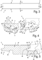
- the invention relates to floor panels (1) for forming a floor covering, which floor panels (1) comprise a first pair of opposite edges (2, 3), as well as a second pair of opposite edges (4, 5).
- the floor panels are rectangular and oblong.
- the represented floor panels (1) are configured such at their edges that they can be mutually coupled according to the so-called fold-down principle, which is a principle known as such and which consists in that such floor panels (1) can be coupled to each other at the first pair of edges (2, 3) by means of a turning movement (R) and can be coupled to each other at the second pair of edges (4, 5) by means of a downward movement (M), wherein the downward movement (M) is the result of the turning movement (R) and thus substantially is realized simultaneously.
- the floor panels (1) are configured such that at their edges (2, 3) and (4, 5) a locking in vertical direction (V) as well as in horizontal direction (H) is obtained, this latter perpendicular to the respective edges.
- such floor panel 1 can be provided with coupling parts (6, 7) at its first pair of edges (2, 3). At the second pair of edges (4, 5) coupling parts (8, 9) are also provided.
- the coupling parts will be described in greater detail in figures 4 to 6 .
- the coupling parts (6, 7) of the first pair of edges (2, 3) can show at least the following characteristics:
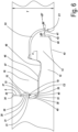
- Figure 4 represent the cross-section according to lines IV-IV of figure 3 .
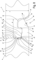
- Figure 6 represents the coupling parts (8, 9) of the second pair of edges (4,5), which are visible in figure 4 , at a larger scale, in coupled condition.
- the second pair of opposite edges (4-5) comprises coupling parts (8-9) on both edges, which allow that two of such floor panels (1) mutually can be coupled to each other.
- the coupling parts (8-9) comprise a horizontally active locking system, which, in a coupled condition of two of such floor panels (1), effects a locking in the plane of the floor panels (1) and perpendicular to the respective edges (4-5).
- the coupling parts (8-9) also comprise a vertically active locking system, which, in a coupled condition of two of such floor panels (1), effects a locking transverse to the plane of the floor panels.
- the coupling parts (8-9) substantially are realized from the material of the floor panel (1) itself.
- the horizontally active locking system of the second pair of edges (4, 5) is formed at least of an upward-directed lower hook-shaped part (10) which is situated on one of said two edges (4), as well as a downward-directed upper hook-shaped part (11), which is situated on the opposite edge (5).
- the upward-directed lower hook-shaped part (10) consists of a lip (12) with an upward-directed locking element (13), which proximally thereof defines a female part (14) in the form of a recess
- the downward-directed upper hook-shaped part (11) consists of a lip (15) with a downward-directed locking element (16) forming a male part (17).
- the male part (17) is not split.
- the coupling parts (8-9) of the second pair of opposing edges (4,5) are configured such that two of such floor panels (1) can be coupled to each other at their respective edges (4-5) by means of a downward movement (M) - in the example involving a downward snapping movement - of the one floor panel in respect to the other.
- the vertically active locking system of the second pair of opposing edges (4,5) comprises vertically active locking parts (18-19-20-21), which, by means of respective locking surfaces (22-23-24-25), define at least a first vertical locking zone (C1) and a second vertical locking zone (C2).
- first vertical locking zone (C1) is located at the distal end of the upward-directed locking element (13); and the second vertical locking zone (C2) is situated at the distal end of the downward-directed locking element (16).
- the vertically active locking parts comprise a first locking part (18) at the edge of the panel at the proximal end of the lip (15) of the upper hook-shaped part (11), a second locking part (19) at the distal end of the downward-directed locking element (16), as well as a third locking part (20) at the distal end of the lip (12) of the lower hook-shaped part (10) and a fourth locking part (21) at the proximal end of the female part (14).
- the first and the third locking part (18, 20) in the coupled condition of two of such floor panels (1), define the first vertical locking zone (C1).
- the second and fourth locking part (19, 21) in the coupled condition of two of such floor panels (1), define said second vertical locking zone (C2).
- the floor panels (1) are configured such that the first vertical locking zone (C1) and the second vertical locking zone (C2) are the only zones where a vertical locking is provided in coupled condition of two such floor panels between the edges of their second pair of opposite edges (4,5).
- the first vertical locking zone (C1) is provided at least at 2/3 of the thickness (T) of the floor panel from the surface of the floor panel.
- the angle ( ⁇ ) between the proximal end of the downward-directed locking element (16) and the horizontal direction in the proximal direction of the upper hook-shaped part (11) is 75°.
- the angle ( ⁇ ) between the proximal end of the upward-directed locking element (13) and the horizontal direction in the distal direction of the lower hook-shaped part (10) is 75°.
- the proximal end of the downward-directed locking element (16) contacts the proximal end of the upward-directed locking element (13).
- the angle ( ⁇ ) of the contact between the proximal end of the downward-directed locking element (16) and the proximal end of the upward-directed locking element (13); and the horizontal direction in the direction towards the distal end of the upward-directed locking element (13) is 75°.
- the proximal end of the downward-directed locking element (16) contacts the proximal end of the upward-directed locking element (13) with pretension.
- the proximal end of the downward-directed locking element (16) contacts the proximal end of the upward-directed locking element (13) without pretension.
- the second locking part (19) is provided by a first undercut (27) at the distal end of the downward-directed locking element (16) and the fourth locking part (21) is provided by a first protrusion (28) at the proximal end of the female part (14).
- the bottom of the first undercut (27) contacts the bottom of the first protrusion (28).
- the included angle ( ⁇ 1) of the first protrusion (28) is larger than the included angle ( ⁇ 2) of the first undercut (27), in the example, ⁇ 2 equals 84° and the angle ⁇ 1 equals 90°.
- the first undercut (27) has a triangular shape with rounded corner points.
- the bottom of the first protrusion (28) in the example is parallel with the surface of the floor panel; the bottom of the first undercut (27) is parallel with the surface of the floor panel. The bottom of the first undercut (27) is substantially parallel with the bottom of the first protrusion (28).
- a space (32) is present in horizontal direction between the distal end of the first protrusion (28) and the proximal end of the first undercut (27); and a space (33) is present between the top end of the first protrusion (28) and the top end of the first undercut (27). Both spaces (32, 33) form one continuous space.
- the first protrusion (28) is provided at its panel edge below a first vertical closing plane (34) of its edge.
- the first vertical closing plane (34) is provided for making contact in coupled condition of two such floor panels with a second vertical closing plane (35) of the corresponding edge of the coupled panel.
- the first undercut (27) is provided below the second vertical closing plane (35).
- a closing plane (S) is provided by the first vertical closing plane (34) contacting the second vertical closing plane (35).
- the downwards extension of the closing plane (S) runs through the contact zone between the second and fourth locking part (19, 21).
- the intersection between the downwards extension of the closing plane (S) and the second vertical contact zone (C2) occurs within the middle quarter of the second vertical contact zone (C2).
- a second undercut (37) is provided above the first protrusion (28).
- the second undercut (37) is provided between the first protrusion (28) and the first vertical closing plane (34).
- the second undercut (37) is smaller than the first undercut (27).
- a first space (38) is present between the coupled opposite edges (4,5) below the contact between the bottom of the first protrusion (28) and the bottom of the first undercut (27) on the one hand and on the other hand distal to the distal end of the downward-directed locking element (16).
- the first space (38) continues into a second space (39) between the bottom part of the downward-directed locking element (16) and the upper part of the lip (12) of the lower hook-shaped part (10).
- a section (40) of the distal end of the downward-directed locking element below the first undercut (27) extends in distal direction beyond the second closing plane (35).
- the first locking part (18) is provided by a second protrusion (41) at the proximal end of the downward directed upper hook-shaped part (11).
- the third locking part (20) is provided by a third undercut (42) at the distal end of the upward-directed locking element (13).
- the bottom of the upward-directed locking element (13) comprises a fourth undercut (43), extending over substantially the full length of the upward-directed locking element (13).
- the height of the fourth undercut (43) increases continuously in the distal direction of the upward directed lower hook-shaped part (10). From the bottom of the floor panel, the third undercut (42) extends deeper into the panel than the fourth undercut (43).
- the third undercut (42) is divided from the fourth undercut (43) by a plane (44) making an angle ( ⁇ 5) of 90° with the horizontal direction of the floor panel.
- the second protrusion (41) extends to the bottom of the floor panel.
- a further undercut (45) is provided at the proximal end of the upper hook-shaped part (11) below the second undercut (37).
- the upper surface of the second protrusion (41) has an angle ( ⁇ 6) 15° with the surface of the floor panel.
- the angle ( ⁇ 7) with the surface of the floor panel of the upper surface of the third undercut (42) is 10°.
- the angle ( ⁇ 7) with the surface of the floor panel of the upper surface of the third undercut (42) is smaller than the angle ( ⁇ 6) with the surface of the floor panel of the upper surface of the second protrusion (41); the difference in the example being 5°.
- the floor panel is configured such that in coupled condition of two such panels at the second pair of opposite edges (4,5) no contact is present between the second protrusion (41) and the third undercut (42).
- the second protrusion (41) extends till the level of the bottom surface of the floor panel
- a space (53) is provided along the full upper side of the upward-directed locking element (13) and along the lip (15) of the upper hook-shaped part (11).
- the second undercut (37) comprises an included angle larger than 90° between its top surface and its side surface.
- the bottom of the downward-directed locking element (16) comprises a concave section (46).
- the bottom of the downward-directed locking element (16) comprises a distal convex section (47) and a proximal convex section (48).
- the concave section (46) is provided between the distal convex section and the proximal distant section.
- the bottom of the downward-directed locking element (16) is configured according to the following characteristics:
- the second vertical locking zone (C2) is provided closer to the surface of the floor panel than the first vertical locking zone (C1).
- the second vertical locking zone (C2) is provided in the bottom half of the thickness (T) of the floor panel.
- guiding surfaces (49, 50), in the example inclined and rounded parts, are present, which are configured such that the male part during the downward movement thereof is guided automatically into the female part.
- the locking part (19) of the second pair of edges (4-5) has a locking surface (23), which, in downward direction, by means of a bend, merges into a lower-situated distal surface (51), wherein this distal surface (51) in downward direction also extends further in distal direction, more particularly is made sloping in downward direction.
- the upper surface of the lip (12) of the lower hook-shaped part (10) comprises a proximal plane which is substantially parallel with the surface of the floor panel and a distal plane which is substantially parallel with the surface of the floor panel, wherein a flat inclined plane is provided between and separating the proximal plane and the distal plane.
- the proximal plane is provided closer to the surface of the floor panel than the distal plane.
- the distal plane is in contact with the downward-directed locking element (16), wherein the contact is made with pretension. It is meant the downward-directed locking element (16) pushes during coupling onto the lip (12), resulting in an elastic bending of the lip (12).
- the upward-directed locking element (13) is elastically bendable, in the exemplary embodiment assisted by the presence of the fourth undercut (43) on the lower side of the lip of the lower hook-shaped part (10).
- the fourth undercut (43) extends substantially along the full length of the upward-directed locking element (13), but not further.
- the fourth undercut (43) is present on the lower side of the lip of the lower hook-shaped part (10).
- the height of the fourth undercut (43) increases continuously in the distal direction of the lower hook-shaped part (10).
- the upward-directed locking element (13) and the downward-directed locking element (16) can be configured such that in coupled condition the proximal end of the downward-directed locking element(16) contacts the proximal end of the upward-directed locking element (13) wherein the upward-directed locking element (13) adopts a somewhat tilted position in respect to its position in uncoupled condition.
- Figure 7 shows - in coupled condition - an alternative embodiment according to the invention for the coupling parts of the second pair of opposite edges (4, 5) shown in figure 6 .
- the coupling parts of the example of figure 7 are to a large extent similar to the coupling parts of figure 6 , however, there are a few differences.
- the second pair of opposite edges (4, 5) - as shown in figure 7 - comprises coupling parts (8, 9) on both edges, which allow that two of such floor panels (1) mutually can be coupled to each other.
- These coupling parts comprise a horizontally active locking system, which, in a coupled condition of two of such floor panels (1), effects a locking in the plane of the floor panels (1) and perpendicular to the respective edges (4-5).
- the coupling parts (8, 9) also comprise a vertically active locking system, which, in a coupled condition of two of such floor panels (1), effects a locking transverse to the plane of the floor panels.
- the coupling parts (8-9) substantially are realized from the material of the floor panel (1) itself.
- the horizontally active locking system of the second pair of edges (4, 5) is formed of an upward-directed lower hook-shaped part (10) which is situated on one of said two edges (4), as well as a downward-directed upper hook-shaped part (11), which is situated on the opposite edge (5).
- the upward-directed lower hook-shaped part (10) consists of a lip (12) with an upward-directed locking element (13), which proximally thereof defines a female part (14) in the form of a recess.
- the downward-directed upper hook-shaped part (11) consists of a lip (15) with a downward-directed locking element (16) forming a male part (17). The male part is not split.
- the coupling parts (8-9) of the second pair of opposing edges (4,5) are configured such that two of such floor panels (1) can be coupled to each other at their respective edges (4-5) by means of a downward movement (M) involving a downward snapping movement of the one floor panel in respect to the other.
- the vertically active locking system of the second pair of opposing edges (4, 5) comprises vertically active locking parts (18, 19, 20, 21), which, by means of respective locking surfaces (22, 23, 24, 25), define at least a first vertical locking zone (C1) and a second vertical locking zone (C2). In coupled condition of two such panels, the first vertical locking zone (C1) is located at the distal end of the upward-directed locking element (13); and the second vertical locking zone (C2) is situated at the distal end of the downward-directed locking element (16).
- the vertically active locking parts comprise a first locking part (18) at the edge of the panel at the proximal end of the lip (15) of the upper hook-shaped part (11), a second locking part (19) at the distal end of the downward-directed locking element (16), as well as a third locking part (20) at the distal end of the lip (12) of the lower hook-shaped part (10) and a fourth locking part (21) at the proximal end of the female part (14).
- the first and third locking part (18, 20) in the coupled condition of two of such floor panels (1), define the first vertical locking zone (C1).
- the second and fourth locking part (19, 21) in the coupled condition of two of such floor panels (1), define the second vertical locking zone (C2).
- the floor panel is configured such that the first vertical locking zone (C1) and the second vertical locking zone (C2) are the only zones where a vertical locking is provided in coupled condition of two such floor panels between the edges of their second pair of opposite edges (4,5).
- the first vertical locking zone (C1) is provided at least at 2/3 of the thickness (T) of the floor panel from the surface of the floor panel.
- the angle ( ⁇ ) between the proximal end of the downward-directed locking element (16) and the horizontal direction in the proximal direction of the upper hook-shaped part (11) is 86° in the example shown in figure 7 .
- the angle ( ⁇ ) between the proximal end of the upward-directed locking element (13) and the horizontal direction in the distal direction of the lower hook-shaped part (10) 86° in the example of figure 7 .
- the proximal end of the downward-directed locking element (16) contacts the proximal end of the upward-directed locking element (13).
- the angle ( ⁇ ) of the contact between the proximal end of the downward-directed locking element (16) and the proximal end of the upward-directed locking element (13); and the horizontal direction in the direction towards the distal end of the upward-directed locking element (13) is 86°.
- the second locking part (19) is provided by a first undercut (27) at the distal end of the downward-directed locking element (16).
- the fourth locking part (21) is provided by a first protrusion (28) at the proximal end of the female part (14). In coupled condition of two such floor panels (1) at the second pair of opposite edges (4, 5), the bottom of the first undercut (27) contacts the bottom of the first protrusion (28).
- the included angle ( ⁇ 1, 90°) of the first protrusion (28) is larger than the included angle ( ⁇ 2, 84°) of the first undercut (27).
- the first undercut (27) has a triangular shape with rounded corner points.
- the first protrusion (28) comprises two inclined outer surfaces (29, 30) with in between the two inclined outer surfaces a vertical surface (31).
- the upper inclined surface (29) is more inclined with respect to the surface of the floor panel than the lower inclined surface (30).
- the bottom of the first protrusion (28) has an angle ( ⁇ 3) of 30° with the surface of the floor panel.
- the bottom of the first undercut (27) also has an angle ( ⁇ 4) of 30° with the surface of the floor panel.
- the bottom of the first undercut (27) is substantially parallel with the bottom of the first protrusion (28).
- a space (32) is present in horizontal direction between the distal end of the first protrusion (28) and the proximal end of the first undercut (27).
- a space (33) is present between the top end of the first protrusion (28) and the top end of the first undercut (27) Both spaces (32, 33) form one continuous space.
- the first protrusion (28) is provided at its panel edge below a first vertical closing plane (34) of its edge.
- the first vertical closing plane (34) is provided for making contact in coupled condition of two such floor panels with a second vertical closing plane (35) of the corresponding edge of the coupled panel.
- the first undercut (27) is provided below the second vertical closing plane (35).
- a closing plane (S) is provided by the first vertical closing plane (34) contacting the second vertical closing plane (35).
- the downwards extension of the closing plane (S) runs through the contact zone between the second and fourth locking part (19, 21).
- the intersection between the downwards extension of the closing plane (S) and the second vertical contact zone (C2) occurs within the middle quarter of the second vertical contact zone (C2).
- the ratio (D/T) of the horizontal distance D between the first vertical closing plane (34) and the distal end of the lip (12) comprising the upward-directed locking element (13), over the thickness (T) of the floor panel is 0.81 in the exemplary floor panels shown in figure 7 .
- a second undercut (37) is provided above the first protrusion (28).
- the second undercut (37) is provided between the first protrusion (28) and the first vertical closing plane (34).
- the second undercut (37) is smaller than the first undercut (27).
- a first space (38) is present between the coupled opposite edges (4,5) below the contact between the bottom of the first protrusion (28) and the bottom of the first undercut (27) on the one hand and on the other hand distal to the distal end of the downward-directed locking element (16).
- This first space (38) continues into a second space (39) between the bottom part of the downward-directed locking element (16) and the upper part of the lip (12) of the lower hook-shaped part (10).
- a section (40) of the distal end of the downward-directed locking element below the first undercut (27) extends in distal direction beyond the second closing plane (35).
- the first locking part (18) is provided by a second protrusion (41) at the proximal end of the downward directed upper hook-shaped part (11).
- the third locking part (20) is provided by a third undercut (42) at the distal end of the upward-directed locking element (13).
- the bottom of the upward-directed locking element (13) comprises a fourth undercut (43), extending over substantially the full length of the upward-directed locking element (13).
- the height of the fourth undercut (43) increases continuously in the distal direction of the upward directed lower hook-shaped part (10). From the bottom of the floor panel, the third undercut (42) extends deeper into the panel than the fourth undercut (43).
- the second protrusion (41) extends to the bottom of the floor panel.
- a further undercut (45) is provided at the proximal end of the upper hook-shaped part (11) below the second undercut (37).
- the upper surface of the second protrusion (41) has an angle ( ⁇ 6) of 30° with the surface of the floor panel.
- the angle ( ⁇ 7) with the surface of the floor panel of the upper surface of the third undercut (42) is 30°.
- the floor panel is configured such that in coupled condition of two such panels at the second pair of opposite edges (4,5) no contact is present between the second protrusion (41) and the third undercut (42).
- the second protrusion (41) extends till the level of the bottom surface of the floor panel.
- a space (53) is provided along the full upper side of the upward-directed locking element (13) and along the lip (15) of the upper hook-shaped part (11).
- the bottom of the downward-directed locking element (16) comprises a concave section (46).
- the bottom of the downward-directed locking element (16) comprises a distal convex section (47) and a proximal convex section (48).
- the concave section (46) is provided between the distal convex section and the proximal distant section.
- the bottom of the downward-directed locking element (16) is configured according to the following characteristics:
- the second vertical locking zone (C2) is provided closer to the surface of the floor panel than the first vertical locking zone (C1).
- the second vertical locking zone (C2) is provided in the bottom half of the thickness (T) of the floor panel.
- guiding surfaces (49, 50), more particularly inclined parts with rounded parts are present, which are configured such that the male part during the downward movement thereof automatically is guided into the female part.
- the locking part (19) of the second pair of edges (4, 5) has a locking surface (23), which, in downward direction, by means of a bend, merges into a lower-situated distal surface (51), wherein this distal surface (51) in downward direction also extends further in distal direction, more particularly is made sloping in downward direction.
- the upper surface of the lip (12) of the lower hook-shaped part (10) comprises a proximal plane which is substantially parallel with the surface of the floor panel and a distal plane which is substantially parallel with the surface of the floor panel.
- An inclined plane - flat in the example of figure 7 - is provided between and separates the proximal plane and the distal plane.
- the proximal plane is provided closer to the surface of the floor panel than the distal plane.
- the upward-directed locking element (13) is elastically bendable, assisted by the presence of a fourth undercut (43) on the lower side of the lip of the lower hook-shaped part (10).
- the fourth undercut (43) extends substantially along the full length of the upward-directed locking element (13), but not further.
- a fourth undercut (43) is present on the lower side of the lip of the lower hook-shaped part (10). The height of the fourth undercut (43) increases continuously in the distal direction of the lower hook-shaped part (10).
- Figure 8 illustrates - in a view similar as in figure 6 - an embodiment of the invention.
- the reference numerals of figure 8 not explained in this paragraph have the same meaning as in figure 6 .
- Figure 8 illustrates two panels according to the invention coupled at their second pair of opposite edges (4, 5).
- the edge (4) of the second pair of opposite edges (4, 5) comprising the upward-directed lower hook-shaped part (10) comprises a first vertical closing plane (34).
- the edge (5) of the second pair of opposite edges (4, 5) comprising the downward-directed upper hook-shaped part (11) comprises a second vertical closing plane (35).
- the first vertical closing plane (34) of the floor panel is provided for contacting the second vertical closing plane (35) of another such floor panel with which the floor panel is coupled at its second pair of opposite edges.
- the contact in coupled condition of two such floor panels at their second pair of opposite edges of the first vertical closing plane (34) with the second vertical closing plane (35) defines a closing plane (S).
- the locking surface (23) of the downward-directed locking element (16) is provided over its full surface proximal to the downwards extension (73) of the second vertical closing plane (35).
- the locking surface of the downward-directed locking element does not extend from proximal to the downwards extension of the second vertical closing plane beyond the downwards extension of the second vertical closing plane. In the example shown, the locking surface of the downward-directed locking element extends up to the downwards extension of the second vertical closing plane.
- the downward-directed locking element (16) does not comprise parts extending in distal direction beyond the downwards extension (73) of the second vertical closing plane (35).
- the second vertical locking zone (C2) is located proximal to the downward extension (73) of the closing plane (S).
- the panel edges shown in figure 8 are provided with bevels (71).
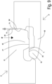
- Figure 9 shows - in a view illustrating the downward movement (M) of two panels for coupling these panels at their second pair of opposite edges - an embodiment of the invention.
- the edge (4) of the second pair of opposite edges (4, 5) comprising the upward-directed lower hook-shaped part (10) comprises a first vertical closing plane (34).
- the edge (5) of the second pair of opposite edges (4, 5) comprising the downward-directed upper hook-shaped part (11) comprises a second vertical closing plane (35).
- the second vertical closing plane (35) of the floor panel is provided for contacting the first vertical closing plane (34) of another such floor panel with which the floor panel is coupled at its second pair of opposite edges.
- the contact of the first vertical closing plane (34) of the floor panel with the second vertical closing plane (35) of the another such floor panel defines a closing plane.
- the distal edge of the downward-directed locking element (16) continuously contacts the proximal end of the opposing edge of the another such floor panel with which the floor panel is being coupled, at the moment the lowest point (77) of the downward-directed locking element (16) being moved downwards reaches the same height level (L) as the highest point (78) of the upward-directed locking element (13) of the another such panel, the gap (G) in horizontal direction and measured in the direction perpendicular to the second pair of opposite edges (4, 5) between the second vertical closing plane (35) of the floor panel and the first vertical closing plane (34) of the another such floor panel is less than 0.15 millimeter, preferably less than 0.1 millimeter, more preferably 0.08 millimeter.
- the panel edges shown in figure 8 are provided with bevels (71).
- Figure 10 illustrates in schematic representation an embodiment of the invention.
- Figure 10 shows a view onto the edge (4) of the second pair of opposite edges comprising the upward-directed lower hook-shaped part (10) of a floor panel according to the invention.
- the coupling parts (6) at the first edge of the first pair of opposite edges comprise a tongue (58) and locking parts (62).
- the coupling parts at the second edge of the first pair of opposite edges comprise a groove and locking parts (63).
- the coupling parts of the first pair of opposite edges are configured such that two of such panels can be coupled to each other at these edges by means of a turning movement, wherein a locking is established in the direction perpendicular to the plane of the so-coupled panels as well as in the direction parallel with the plane of the so-coupled panels and perpendicular to the first pair of opposite edges.
- L1 e.g. 12 mm
- the upward-directed lower hook-shaped part (10) consists of a lip (12) devoid of the upward-directed locking element (13).
- Figure 11 in a view similar to figure 4 , illustrates a feature that can be used in the panels according to the invention.
- Figure 11 illustrates the panel edge (4) comprising the upward-directed lower hook-shaped part (10).
- the reference numerals of figure 11 have the same meaning as in the other figures.
- the panel edge (4) comprising the upward-directed lower hook-shaped part (10) has the additional feature that the lip (12) comprises a slit (75) parallel with the surface of the panel.
- the slit (75) is provided to enhance the ability of the upward-directed locking element (13) to bend backwards when coupling two such panels.
- the slit (75) extends in proximal direction to beyond the upward-directed locking element (13)
- the slit (75) is towards the back of the panel delimited by a lower lip (76).
- the lower lip (76) extends distally less than the distal end of the upward-directed locking element (13).
- the features of figure 11 are of particular interest for panels comprising a substrate out of HDF (High Density Fiberboard).
Landscapes
- Engineering & Computer Science (AREA)
- Architecture (AREA)
- Civil Engineering (AREA)
- Structural Engineering (AREA)
- Floor Finish (AREA)
Applications Claiming Priority (4)
| Application Number | Priority Date | Filing Date | Title |
|---|---|---|---|
| US201962942861P | 2019-12-03 | 2019-12-03 | |
| US202062976504P | 2020-02-14 | 2020-02-14 | |
| PCT/IB2020/060310 WO2021111210A1 (en) | 2019-12-03 | 2020-11-03 | Floor panel for forming a floor covering |
| EP20807504.4A EP4069917B1 (de) | 2019-12-03 | 2020-11-03 | Bodenpaneel zur formung eines bodenbelags |
Related Parent Applications (2)
| Application Number | Title | Priority Date | Filing Date |
|---|---|---|---|
| EP20807504.4A Division EP4069917B1 (de) | 2019-12-03 | 2020-11-03 | Bodenpaneel zur formung eines bodenbelags |
| EP20807504.4A Division-Into EP4069917B1 (de) | 2019-12-03 | 2020-11-03 | Bodenpaneel zur formung eines bodenbelags |
Publications (2)
| Publication Number | Publication Date |
|---|---|
| EP4560089A2 true EP4560089A2 (de) | 2025-05-28 |
| EP4560089A3 EP4560089A3 (de) | 2025-11-05 |
Family
ID=73449123
Family Applications (2)
| Application Number | Title | Priority Date | Filing Date |
|---|---|---|---|
| EP25169724.9A Pending EP4560089A3 (de) | 2019-12-03 | 2020-11-03 | Bodenplatte zur bildung eines bodenbelags |
| EP20807504.4A Active EP4069917B1 (de) | 2019-12-03 | 2020-11-03 | Bodenpaneel zur formung eines bodenbelags |
Family Applications After (1)
| Application Number | Title | Priority Date | Filing Date |
|---|---|---|---|
| EP20807504.4A Active EP4069917B1 (de) | 2019-12-03 | 2020-11-03 | Bodenpaneel zur formung eines bodenbelags |
Country Status (9)
| Country | Link |
|---|---|
| US (2) | US12203274B2 (de) |
| EP (2) | EP4560089A3 (de) |
| CN (2) | CN114729541B (de) |
| CA (1) | CA3157230A1 (de) |
| ES (1) | ES3040667T3 (de) |
| PL (1) | PL4069917T3 (de) |
| SA (1) | SA522432813B1 (de) |
| TW (1) | TWI894181B (de) |
| WO (1) | WO2021111210A1 (de) |
Families Citing this family (19)
| Publication number | Priority date | Publication date | Assignee | Title |
|---|---|---|---|---|
| SE544438C2 (en) | 2019-12-13 | 2022-05-31 | Vilox Ab | Releasable joining system for floor panels, a floor panel, a floor system, a method for laying and a method for releasing a floor panel |
| JP7808587B2 (ja) * | 2020-07-31 | 2026-01-29 | アイ4エフ・ライセンシング・エヌヴィ | パネルおよびカバー材 |
| US11814838B2 (en) * | 2021-07-02 | 2023-11-14 | I4F Licensing Nv | Wall panel for forming a wall covering with multiple panels |
| BE1029978B1 (nl) | 2021-12-02 | 2023-07-03 | Flooring Ind Ltd Sarl | Decoratief paneel. |
| WO2023131873A1 (en) | 2022-01-05 | 2023-07-13 | Flooring Industries Limited, Sarl | Floor covering |
| EP4209643A1 (de) | 2022-01-05 | 2023-07-12 | Flooring Industries Limited, SARL | Bodenbelag |
| WO2023233251A1 (en) | 2022-06-01 | 2023-12-07 | Flooring Industries Limited, Sarl | Wall or ceiling panel, connection member and assembly of a wall or ceiling panel and a connection member |
| US20260079004A1 (en) | 2022-09-27 | 2026-03-19 | Unilin, Bv | Method for inspecting panels, and device used for this |
| BE1030916B1 (nl) | 2022-09-27 | 2024-04-22 | Flooring Ind Ltd Sarl | Werkwijze voor het inspecteren van panelen, en inrichting hierbij aangewend |
| DE202023102907U1 (de) | 2022-09-27 | 2023-08-09 | Flooring Industries Limited, Sarl | Vorrichtung zum Prüfen von Paneelen |
| EP4461902A3 (de) | 2023-05-11 | 2024-11-20 | Unilin, BV | Satz von paneelen |
| US20250012086A1 (en) | 2023-07-03 | 2025-01-09 | Unilin, Bv | Floor or wall covering |
| EP4494861A1 (de) | 2023-07-19 | 2025-01-22 | Unilin, BV | Paneel und verfahren zur herstellung eines paneels |
| BE1031978B1 (nl) | 2023-09-07 | 2025-04-14 | Unilin Bv | Paneel voor het vormen van een bekleding |
| WO2025088483A1 (en) | 2023-10-27 | 2025-05-01 | Unilin, Bv | Covering comprising panels |
| WO2025120491A1 (en) | 2023-12-05 | 2025-06-12 | Unilin, Bv | Connection member for installing panels |
| WO2025252373A1 (de) * | 2024-06-05 | 2025-12-11 | Akzenta Paneele + Profile Gmbh | Dekorpaneel mit durchlaufsicheren verbindungsmitteln |
| EP4660393A1 (de) * | 2024-06-05 | 2025-12-10 | Akzenta Paneele + Profile GmbH | Dekorpaneel mit durchlaufsicheren verbindungsmitteln |
| CN119392884A (zh) * | 2024-10-30 | 2025-02-07 | 常州市贝美家居科技有限公司 | 一种包含耦合部件的地板 |
Citations (8)
| Publication number | Priority date | Publication date | Assignee | Title |
|---|---|---|---|---|
| US20130276398A1 (en) | 2010-12-22 | 2013-10-24 | Akzenta Paneele + Profile Gmbh | Panel |
| US20150267418A1 (en) | 2014-03-24 | 2015-09-24 | Ivc N.V. | Set of mutually lockable panels |
| WO2017068523A1 (en) | 2015-10-23 | 2017-04-27 | Flooring Industries Limited, Sarl | Set of floor panels for forming a floor covering |
| WO2017115202A1 (en) | 2015-12-31 | 2017-07-06 | Flooring Industries Limited, Sarl | Floor panel for forming a floor covering |
| US20170241136A1 (en) | 2014-08-29 | 2017-08-24 | Inotec Global Ltd | Vertical Joint System for a Surface Covering Panel |
| WO2018172955A2 (en) | 2017-03-21 | 2018-09-27 | Flooring Industries Limited, Sarl | Floor panel for forming a floor covering |
| WO2019082141A1 (en) | 2017-10-26 | 2019-05-02 | Flooring Industries Limited, Sarl | PLURALITY OF FLOOR PANELS AND FLOOR PANELS USED IN THIS PLURALITY |
| WO2019137964A1 (en) | 2018-01-09 | 2019-07-18 | Innovations4Flooring Holding N.V. | Panel |
Family Cites Families (15)
| Publication number | Priority date | Publication date | Assignee | Title |
|---|---|---|---|---|
| FR2831908B1 (fr) * | 2001-11-02 | 2004-10-22 | Europ De Laquage Et De Faconna | Dispositif d'assemblage des bords de panneaux, lattes ou lambris |
| DE10224540B4 (de) * | 2002-05-31 | 2007-03-08 | Kronotec Ag | Fussbodenpaneel |
| DE10242647B4 (de) | 2002-09-13 | 2007-06-14 | Kronotec Ag | Paneel |
| US20130139478A1 (en) * | 2005-03-31 | 2013-06-06 | Flooring Industries Limited, Sarl | Methods for packaging floor panels, as well as packed set of floor panels |
| US8925275B2 (en) * | 2010-05-10 | 2015-01-06 | Flooring Industries Limited, Sarl | Floor panel |
| DE202011110452U1 (de) | 2011-01-28 | 2014-02-11 | Akzenta Paneele + Profile Gmbh | Paneel |
| FR3024990B1 (fr) * | 2014-08-25 | 2018-11-16 | Gerflor | Panneau de sol pour la realisation d'un revetement. |
| DE102015006902B3 (de) * | 2015-06-04 | 2016-06-30 | Drägerwerk AG & Co. KGaA | Vorrichtung zur Verarbeitung und Visualisierung von Daten eines Elektro-lmpedanz-Tomographie-Gerätes zu einer Ermittlung und Visualisierung von regionalen Verzögerungen der Ventilation in der Lunge |
| CN114182913A (zh) * | 2017-06-27 | 2022-03-15 | 地板工业有限公司 | 墙壁组件和用于安装墙壁面板的方法 |
| PL3447210T3 (pl) * | 2017-08-23 | 2021-11-15 | Flooring Industries Limited, Sarl | Panele podłogowe do tworzenia pokrycia podłogowego |
| WO2019064113A1 (en) * | 2017-09-28 | 2019-04-04 | Flooring Industries Limited, Sarl | SIGN |
| US11208814B2 (en) * | 2018-01-11 | 2021-12-28 | Flooring Industries Limited, Sarl | Set of floor panels and method for installing this set of floor panels |
| BE1026806B1 (nl) * | 2018-11-27 | 2020-06-30 | Flooring Ind Ltd Sarl | Paneel en werkwijze voor het vervaardigen van dergelijk paneel |
| BE1027083B1 (nl) * | 2019-02-26 | 2020-09-24 | Flooring Ind Ltd Sarl | Glij- of drukschoen voor een doorloopfreesmachine en werkwijze voor het vervaardigen van panelen |
| BE1027299B1 (nl) | 2019-05-22 | 2020-12-22 | Flooring Ind Ltd Sarl | Vloerpaneel voor het vormen van een vloerbekleding |
-
2020
- 2020-11-03 CN CN202080083937.3A patent/CN114729541B/zh active Active
- 2020-11-03 US US17/781,997 patent/US12203274B2/en active Active
- 2020-11-03 PL PL20807504.4T patent/PL4069917T3/pl unknown
- 2020-11-03 EP EP25169724.9A patent/EP4560089A3/de active Pending
- 2020-11-03 CA CA3157230A patent/CA3157230A1/en active Pending
- 2020-11-03 WO PCT/IB2020/060310 patent/WO2021111210A1/en not_active Ceased
- 2020-11-03 EP EP20807504.4A patent/EP4069917B1/de active Active
- 2020-11-03 CN CN202410307849.7A patent/CN118208015A/zh active Pending
- 2020-11-03 ES ES20807504T patent/ES3040667T3/es active Active
- 2020-11-20 TW TW109140740A patent/TWI894181B/zh active
-
2022
- 2022-05-31 SA SA522432813A patent/SA522432813B1/ar unknown
-
2024
- 2024-11-14 US US18/947,494 patent/US20250067059A1/en active Pending
Patent Citations (8)
| Publication number | Priority date | Publication date | Assignee | Title |
|---|---|---|---|---|
| US20130276398A1 (en) | 2010-12-22 | 2013-10-24 | Akzenta Paneele + Profile Gmbh | Panel |
| US20150267418A1 (en) | 2014-03-24 | 2015-09-24 | Ivc N.V. | Set of mutually lockable panels |
| US20170241136A1 (en) | 2014-08-29 | 2017-08-24 | Inotec Global Ltd | Vertical Joint System for a Surface Covering Panel |
| WO2017068523A1 (en) | 2015-10-23 | 2017-04-27 | Flooring Industries Limited, Sarl | Set of floor panels for forming a floor covering |
| WO2017115202A1 (en) | 2015-12-31 | 2017-07-06 | Flooring Industries Limited, Sarl | Floor panel for forming a floor covering |
| WO2018172955A2 (en) | 2017-03-21 | 2018-09-27 | Flooring Industries Limited, Sarl | Floor panel for forming a floor covering |
| WO2019082141A1 (en) | 2017-10-26 | 2019-05-02 | Flooring Industries Limited, Sarl | PLURALITY OF FLOOR PANELS AND FLOOR PANELS USED IN THIS PLURALITY |
| WO2019137964A1 (en) | 2018-01-09 | 2019-07-18 | Innovations4Flooring Holding N.V. | Panel |
Also Published As
| Publication number | Publication date |
|---|---|
| CN114729541B (zh) | 2024-03-19 |
| TW202124824A (zh) | 2021-07-01 |
| US12203274B2 (en) | 2025-01-21 |
| PL4069917T3 (pl) | 2025-10-06 |
| SA522432813B1 (ar) | 2024-03-03 |
| US20250067059A1 (en) | 2025-02-27 |
| EP4069917A1 (de) | 2022-10-12 |
| TWI894181B (zh) | 2025-08-21 |
| CN114729541A (zh) | 2022-07-08 |
| CA3157230A1 (en) | 2021-06-10 |
| EP4069917B1 (de) | 2025-07-09 |
| WO2021111210A1 (en) | 2021-06-10 |
| EP4560089A3 (de) | 2025-11-05 |
| CN118208015A (zh) | 2024-06-18 |
| US20230003034A1 (en) | 2023-01-05 |
| ES3040667T3 (en) | 2025-11-04 |
Similar Documents
| Publication | Publication Date | Title |
|---|---|---|
| EP4069917B1 (de) | Bodenpaneel zur formung eines bodenbelags | |
| US20250012087A1 (en) | Floor panel for forming a floor covering | |
| US12312817B2 (en) | Floor panel for forming a floor covering | |
| US6385936B1 (en) | Floor tile | |
| KR102559702B1 (ko) | 플로어 커버링을 형성하기 위한 플로어 패널 | |
| US11015351B2 (en) | Floor panel for forming a floor covering | |
| EP3839170B1 (de) | Bodenplatte zur formung eines bodenbelags und verfahren zur herstellung einer bodenplatte | |
| EP3973115B1 (de) | Bodenplatte zur formung eines bodenbelags | |
| RU2779864C2 (ru) | Система соединения для панелей напольного настила | |
| RU2779864C9 (ru) | Система соединения для панелей напольного настила | |
| EP3327217A1 (de) | Verbindungsprofil und fliesenanordnung zum horizontalen verlegen |
Legal Events
| Date | Code | Title | Description |
|---|---|---|---|
| PUAI | Public reference made under article 153(3) epc to a published international application that has entered the european phase |
Free format text: ORIGINAL CODE: 0009012 |
|
| STAA | Information on the status of an ep patent application or granted ep patent |
Free format text: STATUS: THE APPLICATION HAS BEEN PUBLISHED |
|
| AC | Divisional application: reference to earlier application |
Ref document number: 4069917 Country of ref document: EP Kind code of ref document: P |
|
| AK | Designated contracting states |
Kind code of ref document: A2 Designated state(s): AL AT BE BG CH CY CZ DE DK EE ES FI FR GB GR HR HU IE IS IT LI LT LU LV MC MK MT NL NO PL PT RO RS SE SI SK SM TR |
|
| PUAL | Search report despatched |
Free format text: ORIGINAL CODE: 0009013 |
|
| AK | Designated contracting states |
Kind code of ref document: A3 Designated state(s): AL AT BE BG CH CY CZ DE DK EE ES FI FR GB GR HR HU IE IS IT LI LT LU LV MC MK MT NL NO PL PT RO RS SE SI SK SM TR |
|
| RIC1 | Information provided on ipc code assigned before grant |
Ipc: E04F 15/02 20060101AFI20250930BHEP |
|
| P01 | Opt-out of the competence of the unified patent court (upc) registered |
Free format text: CASE NUMBER: UPC_APP_0013685_4560089/2025 Effective date: 20251117 |