EP4560079A1 - Control device and control method - Google Patents
Control device and control method Download PDFInfo
- Publication number
- EP4560079A1 EP4560079A1 EP23857411.5A EP23857411A EP4560079A1 EP 4560079 A1 EP4560079 A1 EP 4560079A1 EP 23857411 A EP23857411 A EP 23857411A EP 4560079 A1 EP4560079 A1 EP 4560079A1
- Authority
- EP
- European Patent Office
- Prior art keywords
- control
- velocity
- pressure actuator
- liquid pressure
- target
- Prior art date
- Legal status (The legal status is an assumption and is not a legal conclusion. Google has not performed a legal analysis and makes no representation as to the accuracy of the status listed.)
- Pending
Links
Images






Classifications
-
- E—FIXED CONSTRUCTIONS
- E02—HYDRAULIC ENGINEERING; FOUNDATIONS; SOIL SHIFTING
- E02F—DREDGING; SOIL-SHIFTING
- E02F9/00—Component parts of dredgers or soil-shifting machines, not restricted to one of the kinds covered by groups E02F3/00 - E02F7/00
- E02F9/20—Drives; Control devices
- E02F9/22—Hydraulic or pneumatic drives
- E02F9/2217—Hydraulic or pneumatic drives with energy recovery arrangements, e.g. using accumulators, flywheels
-
- E—FIXED CONSTRUCTIONS
- E02—HYDRAULIC ENGINEERING; FOUNDATIONS; SOIL SHIFTING
- E02F—DREDGING; SOIL-SHIFTING
- E02F9/00—Component parts of dredgers or soil-shifting machines, not restricted to one of the kinds covered by groups E02F3/00 - E02F7/00
- E02F9/20—Drives; Control devices
- E02F9/22—Hydraulic or pneumatic drives
- E02F9/2221—Control of flow rate; Load sensing arrangements
- E02F9/2225—Control of flow rate; Load sensing arrangements using pressure-compensating valves
- E02F9/2228—Control of flow rate; Load sensing arrangements using pressure-compensating valves including an electronic controller
-
- E—FIXED CONSTRUCTIONS
- E02—HYDRAULIC ENGINEERING; FOUNDATIONS; SOIL SHIFTING
- E02F—DREDGING; SOIL-SHIFTING
- E02F9/00—Component parts of dredgers or soil-shifting machines, not restricted to one of the kinds covered by groups E02F3/00 - E02F7/00
- E02F9/20—Drives; Control devices
- E02F9/22—Hydraulic or pneumatic drives
- E02F9/2278—Hydraulic circuits
- E02F9/2296—Systems with a variable displacement pump
-
- E—FIXED CONSTRUCTIONS
- E02—HYDRAULIC ENGINEERING; FOUNDATIONS; SOIL SHIFTING
- E02F—DREDGING; SOIL-SHIFTING
- E02F3/00—Dredgers; Soil-shifting machines
- E02F3/04—Dredgers; Soil-shifting machines mechanically-driven
- E02F3/28—Dredgers; Soil-shifting machines mechanically-driven with digging tools mounted on a dipper- or bucket-arm, i.e. there is either one arm or a pair of arms, e.g. dippers, buckets
- E02F3/36—Component parts
- E02F3/42—Drives for dippers, buckets, dipper-arms or bucket-arms
- E02F3/43—Control of dipper or bucket position; Control of sequence of drive operations
- E02F3/435—Control of dipper or bucket position; Control of sequence of drive operations for dipper-arms, backhoes or the like
- E02F3/437—Control of dipper or bucket position; Control of sequence of drive operations for dipper-arms, backhoes or the like providing automatic sequences of movements, e.g. linear excavation, keeping dipper angle constant
Definitions
- the present invention relates to a control device and a control method that control a position of a control object driven by a liquid pressure actuator or a force acting on the control object.
- a control method for automatically shifting, e.g., a bucket or a working device of a machine such as an excavator driven by an oil pressure actuator to a target position has been developed.
- a response characteristic of a liquid pressure actuator including an oil pressure actuator indicates a strong nonlinearity and greatly varies according to opening and closing of a relief valve. Therefore, it is difficult to achieve an automatic position determining control with a simple control law.
- Patent Literature 1 involves simplifying a control algorithm by solving simultaneous equations of a predictive equation for predicting a position and a velocity of a control object in a next timestep based on prior information on a dynamic characteristic of the control object and an equation representing a sliding mode control law to calculate a valve opening degree instruction as a manipulated variable to the liquid pressure actuator.
- Patent Literature 1 Japanese Unexamined Patent Publication No. 2021-121717
- Patent Literature 1 utilizes the dynamic characteristic of the control object in the calculation of the valve opening degree instruction to the liquid pressure actuator.
- accuracy of the predictive equation cannot be ensured, and therefore a desired control characteristic may not be achieved.
- An object of the present invention is to provide a control device and a control method that achieve a high control performance in position control or force control even in a case where prior information on a dynamic characteristic of a control object is inaccurate and a case where there is a time delay in response of a liquid pressure actuator.
- a control device includes: a movement instruction part that controls a liquid pressure actuator for driving a machine that is a control object; a desirable velocity calculation part that calculates a desirable velocity to be produced in a next timestep for the machine based on a target position and a current position of the machine; a reference velocity calculation part that calculates a reference velocity and a reference generative force based on a quasistatic characteristic of the liquid pressure actuator, the reference velocity being a target velocity closest to the desirable velocity among target velocities from which actuator forces producible by performing PID control or PD control for the liquid pressure actuator are calculable, and the reference generative force being an actuator force to be produced by performing the PID control or PD control when the reference velocity serves as the target velocity; and a manipulated variable calculation part that calculates a manipulated variable for the liquid pressure actuator based on the quasistatic characteristic of the liquid pressure actuator, the reference generative force, and the reference velocity.
- a control method includes: a desirable velocity calculation step of calculating a desirable velocity to be produced in a next timestep for a machine that is a control object and is driven by a liquid pressure actuator, based on a target position and a current position of the machine; a reference velocity calculation step of calculating a reference velocity and a reference generative force based on a quasistatic characteristic of the liquid pressure actuator, the reference velocity being a target velocity closest to the desirable velocity among target velocities from which actuator forces producible by performing PID control or PD control for the liquid pressure actuator are calculable, and the reference generative force being an actuator force to be produced by performing the PID control or PD control when the reference velocity serves as the target velocity; and a manipulated variable calculation step of calculating a manipulated variable for the liquid pressure actuator based on the quasistatic characteristic of the liquid pressure actuator, the reference generative force, and the reference velocity.
- a control law i.e., a control algorithm for determining a manipulated variable u for a liquid pressure actuator in a case where a machine as a control object is driven by the liquid pressure actuator and the control object is shifted to a target position
- an oil pressure actuator 1 shown in FIG. 1 is supposed to serve as the liquid pressure actuator.
- the oil pressure actuator 1 includes an oil pressure pump 11a for providing oil pressure, a pump relief valve 11b, a bleed valve 11c, a pump check valve 11d, main control valves 12 for controlling the oil pressure, a rod-side relief valve 13a, a rod-side check valve 13b, a head-side relief valve 14a, a head-side check valve 14b, and a cylinder 15 actuated by control of the oil pressure.
- the oil pressure actuator 1 includes a regeneration circuit 16.
- the regeneration circuit 16 includes a check valve 16a and a flowrate control valve 16b.
- the embodiment involves a closed unit ball B and functions represented by Formulae (1), (2), (3), and (4) below.
- X denotes a real closed interval
- the liquid pressure actuator is represented by Formulae (6a), (6b), and (6c) below.
- p denotes a position of a control object
- v denotes a velocity of the control object
- M denotes mass of the control object
- the control object represented by Formulae above receives an actuator force f and an external force g.
- the set-valued function ⁇ represents a quasistatic model of the liquid pressure actuator, and is defined as a set-valued function from a current velocity v and the manipulated variable u as a valve opening degree instruction to the actuator force f.
- Specific forms of the set-valued function ⁇ which is the quasistatic model of the oil pressure actuator 1 driven in a state where the regeneration circuit 16 is eliminated from a hydraulic circuit of the oil pressure actuator 1, i.e., in a state where the regeneration circuit 16 is always closed, are shown by Formula (19) in a known Document 1 ( R. Kikuuwe, et al., "A nonsmooth quasi-static modeling approach for hydraulic actuators," J.
- the manipulated variable u ⁇ B which is the second argument of the function ⁇ , represents opening degrees of four main control valves 12 shown in FIG. 1 .
- the manipulated variable u and the opening degrees u* ⁇ [0, 1] (* ⁇ ph, pr, th, tr ⁇ ) of the main control valves 12 are in a relationship represented by Formula (7) below.
- a positive control input which is a manipulated variable u
- a negative control input which is a manipulated variable u
- the embodiment involves a position control law for the oil pressure actuator, which is represented by Formulae (8a), (8b), (8c), and (8d) below.
- K, L, and D denote PID gains
- H denotes a time constant
- p d denotes a target position
- p denotes a current position
- v r denotes a reference velocity
- u denotes an instruction to the actuator
- f ⁇ denotes a reference generative force of the actuator
- a denotes an integral value of errors in a PID controller.
- g denotes an estimation value of the external force.
- the function ⁇ is an inverse function with respect to the second argument of the set-valued function ⁇ , and is a set-valued function in a relationship with the set-valued function ⁇ , the relationship being represented by Formula (9) below.
- Formula (8a) represents a PID control law based on the velocity p ⁇ and the reference velocity v r .
- Formula (8a) representing the PID control law and Formula (8b) representing the sliding mode control law are combined.
- this approach is referred to as differential algebraic relaxation.
- Formula (8b) representing the sliding mode control law, of which right-hand side is set-valued cannot give a unique value, and thus is not appropriate for implementation if used solely; however, this problem can be avoided by the combination with Formula (8a) representing the PID control law, enabling calculation (computation, the same applies hereinafter) of the reference generative force f ⁇
- a symbol such as a dot placed above a sign in each of Formulae is written after the sign in the description, both mean the same.
- a discrete-time control algorithm is considered to implement the control law described above.
- a discretization of the control law represented by Formulae (8) (Formulae (8a) to (8d)) using the backward Euler method results in Formulae (11) below (Formulae (11a) to (11f)).
- T denotes a sampling interval
- k ⁇ Z denotes a discrete-time index
- v s,k can be interpreted as a desirable velocity to be reached in a next step according to the sliding mode control law.
- v f,k can be interpreted as a provisional target velocity to cause the generative force by the liquid pressure actuator to be zero when the PID control law is performed for the liquid pressure actuator.
- Formula (12a) can be rewritten as Formula (14) below by using Formula (13).
- f ⁇ sat ⁇ s 1 / A , ⁇ f , k , B A ⁇ s , k ⁇ ⁇ f , k
- the function ⁇ s and the function ⁇ s are single-valued functions that have a relationship with the function ⁇ s and the function ⁇ s as shown in Formulae (16) and (17) below.
- f ⁇ s ⁇ ⁇ u ⁇ f ⁇ ⁇ + ⁇ f , u ⁇ s ⁇ f ⁇ ⁇ ⁇ , sat ⁇ ⁇ B f
- the set-valued function ⁇ can be obtained from a quasistatic characteristic (relationship between the velocity v in a steady state, the generative force f, and the manipulated variable u representing the valve opening degree instruction) of the liquid pressure actuator.
- the set-valued function ⁇ can be obtained from the set-valued function ⁇ by using Formula (9).
- the single-valued function ⁇ s and the single-valued function ⁇ s can be obtained by using these relationships, and Formulae (16) and (17).
- Specific forms of the single-valued function ⁇ s and the single-valued function ⁇ s for the oil pressure actuator 1 driven in the state where the regeneration circuit 16 is eliminated from the hydraulic circuit of the oil pressure actuator 1 shown in FIG. 1 i.e., in the state where the regeneration circuit 16 is always closed are shown by Formulae (34) and in Section III.C in the known Document 2.
- a pair ⁇ f k ⁇ , v r,k ) in real numbers for a generative force f k producible in the oil pressure actuator 1 and a target velocity v r,k to produce the generative force f k at a time k satisfies two Formulae (18a) and (18b) below.
- ⁇ r , k ⁇ f , k + f ⁇ k / A f ⁇ k ⁇ ⁇ ⁇ r , k B
- Formulae (15b), (15c), and (15d) represent a step (reference velocity calculation step) of calculating the reference velocity v r,k and the reference generative force f k ⁇ based on the quasistatic characteristic of the liquid pressure actuator, the reference velocity being a target velocity closest to the desirable velocity v s,k among target velocities v f,k from which actuator forces producible by performing PID control for the oil pressure actuator 1 are calculable, and the reference generative force being an actuator force to be produced by performing the PID control when the reference velocity v r,k serves as the target velocity v f,k .
- the conventional control law in the known Document 2 which is based on a quasistatic model similarly to the embodiment, involves a double-implicit implementation scheme to deal with set-valuedness of the sliding mode control law.
- both the control law and a dynamic characteristic model of a control object are discretized by the backward Euler method and combined to construct a control algorithm.
- the control method based on the differential algebraic relaxation according to the embodiment which does not require the dynamic characteristic model for the implementation, is more robust against modeling errors than the conventional control method. Additionally, sensitivity to the modeling errors and deadtime can be adjusted by adjusting a gain of the PID controller connected by the differential algebraic relaxation.
- the desirable velocity v s,k to be produced in the liquid pressure actuator in the next timestep is calculated based on the target position p d,k and the current position p k of the liquid pressure actuator, specifically, based on the target position p d,k , the current position p k , the target velocity v d,k obtained from these positions, and the current velocity v k (the desirable velocity calculation step, Formula (19a)).
- the reference velocity v r,k and the reference generative force f k ⁇ are then calculated based on the quasistatic model ⁇ of the liquid pressure actuator, the reference velocity being a target velocity closest to the desirable velocity v s,k among target velocities v f,k from which actuator forces f producible by performing PID control or PD control for the liquid pressure actuator are calculable, and the reference generative force being an actuator force to be produced by performing the PID control or PD control when the reference velocity v r,k serves as the target velocity (the reference velocity calculation step, Formulae (19b) to (19e)).
- the manipulated variable u k for the liquid pressure actuator is calculated based on the quasistatic model ⁇ of the liquid pressure actuator, and the calculated reference generative force f k ⁇ and reference velocity v r,k (the manipulated variable calculation step, Formula (19f)).
- the oil pressure actuator 1 includes the regeneration circuit 16 as shown in FIG. 1 .
- the regeneration circuit 16 transfers hydraulic liquid (hydraulic oil) from a rod-side chamber to a head-side chamber by use of potential energy of a link.
- a pressure difference caused by the external force g between the rod-side chamber and the head-side chamber can be approximated to g/A - .
- u reg denotes an opening degree of the flowrate control valve 16b of the regeneration circuit 16.
- the coefficient c reg is defined as C reg a reg ⁇ 2/ ⁇ , where ⁇ denotes mass density of the hydraulic oil, a reg denotes a maximum opening area of the flowrate control valve 16b, and C reg denotes a discharge coefficient.
- v reg q reg /A h .
- the variable v reg indicates a non-negative value due to an effect of the check valve 16a of the regeneration circuit 16.
- An expansion of the control law represented by Formulae (8) based on the increase v reg in the cylinder velocity for compensation for an effect of the regeneration circuit 16 results in a control law represented by Formulae (21a), (21b), and (21c) below.
- the switching surface is reached at a velocity reduced by v reg compared to a case without the compensation. Therefore, a control that prevents an excessive increase in the velocity can be performed.
- a value of the variable v reg,k can be computed by using Formula (20) for each timestep relevant to computation.
- gravity acting on the cylinder 15, which is derived from a joint angle and mass of the link, can be used as the external force g.
- a control unit 50 serving as a position control device according to the embodiment is installed in an excavator 30 as shown in FIG. 2 and controls movement of the excavator 30.
- the excavator 30 includes a lower traveling body 31, an upper slewing body 32, and a working device 40.
- the lower traveling body 31 causes the excavator 30 to travel, which is, for example, a crawler.
- the upper slewing body 32 is slewably attached to the lower traveling body 31 via a slewing motor 47.
- the upper slewing body 32 is provided with, e.g., a cab that allows an operator to operate the excavator 30, and the working device 40.
- the working device 40 includes a boom 41 rotatably attached to the upper slewing body 32, an arm 42 rotatably attached to the boom 41, and a bucket 43 rotatably attached to the arm 42 for performing, e.g., excavation.
- the working device 40 includes a boom cylinder 44 that is connected to the upper slewing body 32 and the boom 41 and moves the boom 41, an arm cylinder 45 that is connected to the boom 41 and the arm 42 and moves the arm 42, a bucket cylinder 46 that is connected to the arm 42 and the bucket 43 and moves the bucket 43, and the slewing motor 47 that is connected to the lower traveling body 31 and the upper slewing body 32 and moves the upper slewing body 32.
- Each of the boom cylinder 44, the arm cylinder 45, the bucket cylinder 46, and the slewing motor 47 (hereinafter, also referred to as actuators 44 to 47, respectively) is an oil pressure actuator driven by oil pressure.
- the control unit 50 is installed in the excavator 30, and includes a control part 51, a storage part 52, a display part 53, and an input part 54 as shown in the block diagram of FIG. 3 .
- the control unit 50 is connected with, e.g., a position sensor 48, a velocity sensor 49, and the actuators 44 to 47, and controls movement of each portion of the excavator 30.
- the control part 51 is a computer device including, e.g., a central processing unit (CPU), a read only memory (ROM), and a random access memory (RAM), and controls movement of the excavator 30.
- the control part 51 performs each function as the control part 51 shown in FIG. 3 by loading various operation programs and data stored in the ROM of the control part 51 and the storage part 52 into the RAM to cause the CPU to operate.
- the control part 51 operates as a desirable velocity computation part 511 (desirable velocity calculation part), a reference velocity computation part 512 (reference calculation computation part), a manipulated variable computation part 513 (manipulated variable calculation part), an external force estimation part 514, and a movement instruction part 515.
- the desirable velocity computation part 511, the reference velocity computation part 512, and the manipulated variable computation part 513 calculate a manipulated variable u for each of the actuators 44 to 47 for moving the working device 40, based on measured values output by the position sensor 48 and the velocity sensor 49, and a target position of the bucket 43, specifically, a target position of a leading end of the bucket 43 (hereinafter, referred to as a bucket leading end 43a) corresponding to a predetermined portion of the excavator 30.
- the external force estimation part 514 estimates a magnitude of an external force acting on each of the actuators 44 to 47. How an external force is estimated is not particularly limited; for example, it may be estimated based on an output from, e.g., a sensor (not shown) provided to each of the actuators 44 to 47.
- the movement instruction part 515 controls each of the actuators 44 to 47 based on the manipulated variables u calculated by the manipulated variable computation part 513 to move the upper slewing body 32, the boom 41, the arm 42, and the bucket 43.
- the storage part 52 includes a non-volatile memory such as a hard disk or a flash memory, and stores, e.g., various setting parameters and a control algorithm for calculating the manipulated variable u.
- a non-volatile memory such as a hard disk or a flash memory
- the display part 53 includes a displaying device such as a liquid-crystal or organic electro-luminescence (EL) panel, and displays, e.g., the various setting parameters and detection values by the position sensor 48 and the velocity sensor 49.
- a displaying device such as a liquid-crystal or organic electro-luminescence (EL) panel
- displays e.g., the various setting parameters and detection values by the position sensor 48 and the velocity sensor 49.
- the display part 53 according to the embodiment is a liquid crystal panel provided in the cab of the excavator 30.
- the input part 54 is an input device for inputting the various setting parameters for moving the excavator 30, e.g., the target position of the bucket leading end 43a.
- the input part 54 includes, e.g., a touch panel provided on the display part 53.
- the position sensor 48 is a sensor that detects a position of the working device 40 of the excavator 30 that is a control object.
- the position sensor 48 according to the embodiment includes a slewing angle sensor 484 that detects an angle of the upper slewing body 32, a boom angle sensor 481 that detects an angle of the boom, an arm angle sensor 482 that detects an angle of the arm, and a bucket angle sensor 483 that detects an angle of the bucket.
- the control part 51 calculates lengths of the boom cylinder 44, the arm cylinder 45, and the bucket cylinder 46 (hereinafter, also referred to as cylinders 44 to 46, respectively) and an angle of the slewing motor 47 from the angle of each portion of the working device 40 detected by the boom angle sensor 481, the arm angle sensor 482, the bucket angle sensor 483, and the slewing angle sensor 484, and performs position control of the bucket leading end 43a based on the calculated length of each of the cylinders 44 to 46 and the angle of the slewing motor 47.
- the velocity sensor 49 is a sensor that detects a velocity of each portion of the working device 40.
- the velocity sensor 49 according to the embodiment includes a slewing angular velocity sensor 494 that detects an angular velocity of the upper slewing body 32, a boom velocity sensor 491 that detects an extension and contraction velocity of the boom cylinder, an arm velocity sensor 492 that detects an extension and contraction velocity of the arm cylinder, and a bucket velocity sensor 493 that detects an extension and contraction velocity of the bucket cylinder.
- a position control process for the bucket leading end 43a by the control unit 50 will be described below.
- An exemplary control algorithm to calculate a manipulated variable u for each cylinder 44 to 46 serving as the oil pressure actuator as shown in the block diagram of FIG. 4 will be described.
- the embodiment is assumed to involve the cylinders 44 to 46 only, but is not limited to this.
- a controller may be configured to additionally involve a slewing angle of the upper slewing body 32, based on a coordinates of the target position p d , to perform the position control of the bucket leading end 43a. Specifically, as shown in FIG.
- the position control of the bucket leading end 43a may be performed by moving the slewing motor 47 serving as a liquid pressure actuator based on the slewing angle sensor 484 as a position sensor 48 and the slewing angular velocity sensor 494 as a velocity sensor 49, and by combining movements of the boom 41, the arm 42, and the bucket 43.
- the control part 51 calculates a manipulated variable u for each of the cylinders 44 to 46 based on, e.g., a target position, a desired behavior, a current position, and a current velocity of a given control object.
- the desired behavior is represented by, e.g., the time constant, which involves convergence of movement of the control object to the target position.
- the operator of the excavator 30 inputs and sets a target position p d of the bucket leading end 43a through the input part 54 (Step S11).
- a coordinate of the target position p d may be input through the input part 54 including the touch panel, or a coordinate of the bucket leading end 43a manually shifted with a control lever may be set as the target position p d .
- a coordinate on a planned surface prestored in the storage part 52 may be read out and set as the target position p d .
- the operator inputs and sets parameters such as the time constant H representing the desired behavior.
- the parameters may be set by reading out values prestored in the storage part 52.
- the control part 51 calculates a target length of each of the cylinders 44 to 46 at the target position p d by inverse kinematics from the input target position p d (Step S12). As shown in FIG. 4 , each of the cylinders 44 to 46 is controlled to extend or contract such that the lengths of the cylinders 44 to 46 become the respective target lengths, so that the position control of the bucket leading end 43a is performed.
- the desirable velocity computation part 511 of the control part 51 calculates the desirable velocity v s,k to be produced in the next timestep, which is the desirable velocity computation step (Step S13). Specifically, the control part 51 acquires angle data of each portion of the working device 40 from the boom angle sensor 481, the arm angle sensor 482, and the bucket angle sensor 483 (hereinafter, also referred to as angle sensors 481 to 483, respectively). The control part 51 calculates a current position p k representing a length of each of the cylinders 44 to 46 based on the acquired angle data.
- the control part 51 calculates the desirable velocity v s,k of each of the cylinders 44 to 46 based on the calculated current position p k (m), the set target position p d,k (m), the target velocity v d,k (m/s), the time constant H (s), and Formula (15a) or (22).
- the control period is, e.g., 10 ms (milliseconds), but is not particularly limited.
- the reference velocity computation part 512 of the control part 51 calculates the reference velocity v r,k and the reference generative force f k ⁇ in the next timestep, based on the current velocity v k (m/sec), the set PID gains K, L, and D, the control period T (sec), and Formulae (15b) to (15e) or Formulae (19b) to (19e), which is the reference velocity computation step (Step S14).
- the reference velocity computation part 512 acquires the current velocity v k of each of the cylinders 44 to 46 from the boom velocity sensor 491, the arm velocity sensor 492, and the bucket velocity sensor 493.
- the reference velocity computation part 512 then calculates the reference velocity v r,k and the reference generative force f k ⁇ , based on the quasistatic model ⁇ of the liquid pressure actuator, the reference velocity being a target velocity closest to the desirable velocity v s,k among target velocities v f,k from which actuator forces f producible by performing PID control or PD control for the liquid pressure actuator are calculable, and the reference generative force being an actuator force to be produced by performing the PID control or PD control when the reference velocity v r,k serves as the target velocity.
- the manipulated variable computation part 513 of the control part 51 calculates the manipulated variable u k for each of the cylinders 44 to 46, which is the manipulated variable computation step (Step S15). Specifically, the manipulated variable computation part 513 calculates the manipulated variables u k , based on the reference velocity v r,k and the reference generative force f k ⁇ calculated in Step S14, and the quasistatic model ⁇ of the liquid pressure actuator (Formulae (15f), (17)).
- the movement instruction part 515 of the control part 51 outputs the calculated manipulated variables u k to the respective cylinders 44 to 46 to move the boom 41, the arm 42, and the bucket 43 so that the bucket leading end 43a is shifted (Step S16).
- the control part 51 acquires a new current position p k of each of the cylinders 44 to 46 from the position sensor 48. In a case where a difference between the acquired current position p k and the target position p d,k is not larger than a certain preset threshold (YES in Step S17), the control part 51 ends the position control.
- Step S17 the control part 51 returns to Step S13, i.e., the desirable velocity computation step.
- the control part 51 then calculates manipulated variables u k in the timestep based on the control algorithm, and shifts the bucket leading end 43a.
- the control part 51 repeats this to perform the position control for causing the position of the bucket leading end 43a to reach the target position p d .
- the reference velocity and the actuator force are calculated by combining the PID control law or the PD control law that causes the velocity of the control object to follow the reference velocity with the sliding mode control law, and the manipulated variable for the liquid pressure actuator is calculated based on the quasistatic characteristic of the liquid pressure actuator. Therefore, a control independent of the dynamic characteristic model of the control object can be performed. Accordingly, a high control performance can be achieved even in a case where prior information on a dynamic characteristic of a control object is inaccurate and a case where there is a time delay in response of a liquid pressure actuator.
- Simulations of the position control of an oil pressure actuator based on the control law according to the embodiment will be described below.
- the simulations were run by using a realtime simulator for a 13 ton-class oil pressure excavator.
- a position of an arm leading end was controlled by applying the control law according to the embodiment to actuators for each axis by use of kinematics.
- a sampling interval for the realtime simulator was 0.1 ms, and a sampling interval for a controller was 10 ms.
- the realtime simulator and the controller were connected with each other by User Datagram Protocol/Internet Protocol (UDP/IP), and were capable of transmitting and receiving, e.g., joint angle information and a control input to and from each other.
- UDP/IP User Datagram Protocol/Internet Protocol
- a generative force of a cylinder in the realtime simulator was calculated based on the quasistatic model of the oil pressure actuator disclosed in the known Document 1 described above.
- a generative force of the arm cylinder was calculated based on a quasistatic model covering the regeneration circuit disclosed in the known Document 1.
- a filter represented by Formula (23) below was interposed between the actuator model and the controller to simulate a dynamic characteristic of the oil pressure actuator and deadtime in the oil pressure actuator.
- u f denotes a control input after filtering.
- T d 300 msec
- ⁇ 0 94.2 rad/sec
- ⁇ 1, respectively.
- FIG. 6 shows a posture of the excavator 30 and a path of a target position q d .
- the target position q d and a rate of change of the target position q d with respect to time are as represented by Formula (24) below; the rate of change of the target position q d with respect to time was set to be constant.
- q d ⁇ q x q y T , q ⁇ d 0.5 m / s
- control simulations for comparing the control method according to the embodiment and the conventional control method were run under the same conditions.
- a control law A which is a conventional sliding mode control law based on double-implicit implementation as shown in FIG. 7A (control law according to the known Document 2)
- a control law B which is the PID control law according to the embodiment as shown in FIG. 7B
- the time constant H indicating the slope of the switching surface was set to 1.0 s.
- the proportional gain K p , the derivative gain K d , and the integral gain K i were set to 3 ⁇ 10 8 N/m, 3 ⁇ 10 8 N ⁇ s/m, and 0, respectively.
- the values of these gains result from adjustment by trial and error with repeated simulations.
- FIG. 8 shows results of the simulations.
- the control method according to the embodiment with regeneration circuit compensation (a proposed method in the drawing) achieves the best results with smaller errors between the target position and the position of the arm leading end (tip position in FIG. 8 , and similarly in subsequent drawings) over the entire path.
- the control method according to the embodiment without the regeneration circuit compensation (control law B) causes large errors due to the effect of the regeneration circuit, during vertical lowering and horizontal pulling when the regeneration circuit opens.
- the control law B also causes the oscillation over the entire path.
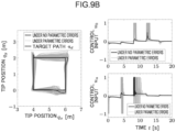
- FIG. 9A , FIG. 9B , and FIG. 9C show results of the simulations.
- a comparison between FIG. 9C for the control law A, and FIG. 9A for the control law B without the regeneration circuit compensation and FIG. 9B with the regeneration circuit compensation shows that paths resulting from the simulations (paths under the parametric errors) in FIG. 9A and FIG. 9B come closer to a desirable path under no parametric errors.
- the results seem to be ascribed to the fact that the control method according to the embodiment is independent of the dynamic characteristic model of the control object, i.e., has low model dependence.
- control law A reflected the effects of the parametric errors more largely, seemingly because the control law involves the deadtime compensation based on the quasistatic model and the dynamic characteristic model of the control object.
- FIG. 9A and FIG. 9B shows that a compensation for the effect of the regeneration circuit even under the parametric errors enables a tip path to come closer to the path of the target position q d .
- control device and the control method for the position control involve performing the position control based on the sliding mode control algebraically connected with PID control or PD control and are independent of the dynamic characteristic model of the control object, and thus are hardly affected by, e.g., the parametric errors and the deadtime. Therefore, even an oil pressure actuator with a long deadtime can be controlled appropriately.
- the control device and the control method which are based on the quasistatic model of the oil pressure actuator, can deal with the strong nonlinearity of the oil pressure actuator.
- control device and the control method according to the embodiment which involve the expansion for compensating for the effect of the regeneration circuit, are applicable to a liquid pressure actuator having a regeneration circuit.
- the extension and contraction velocity of each of the cylinders 44 to 46 is measured with the velocity sensor 49, but this is not the only way.
- the control part 51 may calculate the velocity of each of the cylinders 44 to 46 based on the angle data measured by the respective angle sensors 481 to 483.
- a force control device and a force control method will be described with an exemplary admittance control of the control object driven by the same oil pressure actuator 1 in the first embodiment.
- a control system according to the embodiment is different from the first embodiment in that the control system includes a feedback loop for performing the force control and a control part 51' includes a reference position computation part 516 (reference position calculation part) to achieve this.
- the other constituents, which are the same as those in the first embodiment, are denoted by the same reference numerals, and the description thereof will be omitted.
- the control system performs the admittance control of movement of the oil pressure actuator 1 based on inputs of a measured value of a force f e (hereinafter, also referred to as a counterforce) applied to the oil pressure actuator 1 as the control object by an environment and a target applied force f d that is a target value of a force applied to the environment by the oil pressure actuator 1.
- a force f e hereinafter, also referred to as a counterforce
- f d a target applied force applied to the environment by the oil pressure actuator 1.
- the admittance control according to the embodiment is force control based on the position control.
- an internal position controller that performs the position control according to the first embodiment controls and causes a position p of a rod of the oil pressure actuator 1 as the control object to follow a position q of a virtual object having a target dynamic characteristic of the control object.
- the target dynamic characteristic of the virtual object includes a dynamic characteristic defined by target inertia and target viscosity of the control object.
- the virtual object according to the embodiment is represented as a mass damper system obtained by modeling the dynamic characteristic of the oil pressure actuator 1. The virtual object is assumed to receive the target applied force f d , and the measured counterforce f e which is a force that the oil pressure actuator 1 receives from a rigid external environment due to a contact between the control object and the environment.
- a control law according to the embodiment i.e., a control algorithm for determining a manipulated variable u for a liquid pressure actuator in a case where a machine as a control object is driven by the liquid pressure actuator and a force caused by a contact between the control object and a rigid environment is controlled will be described below.
- the embodiment involves a function represented by Formula (26) below, which is referred to as a normal cone.
- the liquid pressure actuator as the control object is represented by Formulae (27) (Formulae (27a), (27b), and (27c)) below.
- p denotes a position of the control object
- v denotes a velocity of the control object
- M denotes mass of the control object
- the control object represented by Formulae above receives the generative force f of the actuator, the external force (disturbance) g, and the counterforce f e from the environment.
- the set-valued function ⁇ represents the same quasistatic model of the liquid pressure actuator as the first embodiment, and is defined as a set-valued function from the current velocity v and the manipulated variable u as the valve opening degree instruction to the generative force f of the actuator.
- the control input u ⁇ B determines the opening degree of the flowrate control valve.
- the flowrate control valve is opened to generate an oil flow in the liquid pressure actuator in a direction to cause the liquid pressure actuator to extend if u > 0 or in a direction to cause the liquid pressure actuator to contract if u ⁇ 0. M may not be already known, and p can be acquired by a position sensor.
- the embodiment involves an admittance control law represented by Formulae (28) below.
- Formulae (28) K p r ⁇ p + B p ⁇ r ⁇ p ⁇ ⁇ g ⁇ f ⁇ ⁇ ⁇ p ⁇ r , sgn q ⁇ p + H q ⁇ ⁇ p ⁇ r u ⁇ ⁇ p ⁇ r f ⁇
- Formula (28a) represents a dynamic characteristic of the virtual object driven by the target applied force f d and the measured counterforce f e from the environment.
- the third term N [-vm, vm] (q ⁇ ) on the right-hand side of Formula (28a) has an effect of limiting the velocity q ⁇ of the virtual object within an interval [- v m , v m ], due to the definition of the normal cone represented by Formula (26).
- Formulae (28b) to (28d) serve as a position controller that causes the position p of the control object to follow the position q of the virtual object, and represent a control law similar to that of the position controller according to the first embodiment.
- the position controller has adjustable parameters including PID gains K, B and the time constant H.
- the algorithm for calculating from ⁇ f d,k , f e,k , p k , g k ⁇ a control input u k from a force controller according to the embodiment to the liquid pressure actuator is obtained by following the similar procedure including the discretization to the first embodiment, and represented by Formulae 29 below.
- A ⁇ KT + B
- k denotes the discrete-time index
- T denotes the sampling interval
- the algorithm of the force control according to the embodiment is represented by Formulae (29c) to (29i) corresponding to Formulae (19) representing the algorithm of the position control according to the first embodiment and additional Formulae (29a) and (29b) for constituting the force controller.
- the internal position controller based on the position control method according to the first embodiment is used to perform the force control. Accordingly, a high control performance can be achieved even in a case where prior information on a dynamic characteristic of a control object is inaccurate and a case where there is a time delay in response of a liquid pressure actuator.
- control part 51' of a control unit 50' includes the reference position computation part 516 (reference position calculation part), unlike the control part 51 according to the first embodiment.
- the reference position computation part 516 calculates a reference position by using the virtual object having the dynamic characteristic of the machine including the oil pressure actuator as the control object. Specifically, as shown in the algorithm above, the target applied force set as a target value of a force applied to the environment by the oil pressure actuator and a measured value of the counterforce acting on the oil pressure actuator from the environment by a force sensor 60 included in the oil pressure actuator are input to a model of the virtual object. Then, the reference position at which the control object, more specifically, the rod of the oil pressure actuator represented by the virtual object, is to be located in the next timestep is calculated.
- the force sensor 60 that measures the force acting on the oil pressure actuator is installed in the oil pressure actuator, or may be disposed outside the oil pressure actuator.
- the desirable velocity computation part 511 calculates the desirable velocity by using the reference position calculated by the reference position computation part 516. Specifically, the desirable velocity computation part 511 calculates the desirable velocity by using the reference position as the target position for the algorithm according to the first embodiment.
- the reference position q output by the reference position computation part 516 is input to the control law according to the first embodiment serving as the internal position controller to perform the control, so that, as a whole, the force control of the control object is performed.
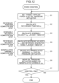
- FIG. 12 is a flowchart showing a flow of the force control according to the embodiment.
- the target applied force f d of the oil pressure actuator is set (Step S31).
- the reference position q is computed based on the set target applied force f d and the measured value of the force f e acting on the oil pressure actuator (Step S32). Parameters such as the time constant H given when the control starts are predetermined as in the first embodiment.
- the reference position computation part 516 of the control part 51' calculates the reference position at which the rod of the oil pressure actuator as the control object is to be located in the next timestep, which is the reference position computation step.
- An algorithm for calculating the reference position is represented by Formulae (29a) and (29b) above.
- Steps S33 to S36 correspond to Steps S13 to S16 ( FIG. 5 ) according to the first embodiment except that the reference position calculated in Step S31 is input as the target position.
- Steps S33 to S36 the internal position controller computes the manipulated variable u, so that the movement of the oil pressure actuator as the control object is controlled.
- the control part 51' repeats Steps S31 to S37 (NO in Step S37) until the control process is ended by, e.g., an end instruction by the operator or expiration of a predetermined operation time.
- the control system ends the control process (YES in Step S37) when a predetermined end condition such as the end instruction by the operator or the expiration of the predetermined operation time is satisfied.
- the control part 51' according to the embodiment achieves the force control of the control object by executing the process described above.
- the reference velocity and the actuator force are calculated by combining the PID control law or the PD control law that causes the velocity of the control object to follow the reference velocity with the sliding mode control law, and the force control of the control object is performed by using the control law according to the first embodiment for calculating the manipulated variable for the liquid pressure actuator based on the quasistatic characteristic of the liquid pressure actuator. Therefore, a control independent of the dynamic characteristic model of the control object can be performed. Accordingly, a high control performance can be achieved even in a case where prior information on a dynamic characteristic of a control object is inaccurate and a case where there is a time delay in response of a liquid pressure actuator.
- the hydraulic testing machine includes a proportional flowrate control solenoid valve (uppermost modular valve), a relief valve, and a check valve.
- the flowrate of hydraulic oil supplied from a pump unit was constant, which was 4.17 ⁇ 10 -4 m 3 /s, and the maximum force of an oil pressure cylinder was 1.56 ⁇ 10 -3 N.
- the control unit acquires measured values of the position p of the rod and the counterforce f e from the environment, from a linear encoder and a load cell of the oil pressure cylinder.
- the control input u is converted into an input voltage for the flowrate control valve by a D/A conversion board.
- a rubber board fixed to a rigid wall was used as the environment in contact with the oil pressure cylinder. Further, a metal plate was placed on a surface of the rubber board so that only a load button of the load cell comes into contact with the environment.
- contact experiments with rubber boards having three different hardnesses were conducted to make a comparison.
- the rubber boards have hardnesses of a Shore A hardness of about 50 HS (Shore A50), a Shore A hardness of about 65 HS (Shore A65), and a Shore A hardness of about 70 HS (Shore A70), with a smaller number indicating a softer rubber board.
- FIGS. 14A, 14B, and 14C show results of contact force control with respect to a stepwise target applied force f d .
- the measured counterforce f from each of the environments with the hardnesses follows the target applied force f d successfully.
- FIGS. 15A, 15B, and 15C show results of contact force control with respect to a sinusoidal target applied force f d .
- the measured counterforce f from each of the environments with the hardnesses follows the target applied force f d successfully.
- the method for the force control according to the embodiment can cause a force applied to a rigid environment by an oil pressure actuator in contact with the environment to follow a target applied force properly.
- the present invention is suitable for position control and force control of a machine actuated by a liquid pressure actuator. Particularly, the present invention is suitable for automatic position determining control and admittance control of a construction machine actuated by an oil pressure actuator.
- a control device includes: a movement instruction part that controls a liquid pressure actuator for driving a machine that is a control object; a desirable velocity calculation part that calculates a desirable velocity to be produced in a next timestep for the machine based on a target position and a current position of the machine; a reference velocity calculation part that calculates a reference velocity and a reference generative force based on a quasistatic characteristic of the liquid pressure actuator, the reference velocity being a target velocity closest to the desirable velocity among target velocities from which actuator forces producible by performing PID control or PD control for the liquid pressure actuator are calculable, and the reference generative force being an actuator force to be produced by performing the PID control or PD control when the reference velocity serves as the target velocity; and a manipulated variable calculation part that calculates a manipulated variable for the liquid pressure actuator based on the quasistatic characteristic of the liquid pressure actuator, the reference generative force, and the reference velocity.
- the liquid pressure actuator may include a regeneration circuit, and the desirable velocity may be calculated based on the target position and the current position of the machine, an opening degree of a flowrate control valve of the regeneration circuit, and an estimation value of a flowrate of a hydraulic liquid flowing through the regeneration circuit.
- the machine may be driven by a plurality of the liquid pressure actuators, the manipulated variable calculation part may calculate the manipulated variable for each of the liquid pressure actuators, and the movement instruction part may shift a predetermined portion of the machine to the target position by controlling each of the liquid pressure actuators based on the calculated manipulated variables.
- the control device may include an external force estimation part that estimates an external force applied to the machine, and the reference velocity calculation part may calculate the reference velocity and the reference generative force based on the external force estimated by the external force estimation part.
- the liquid pressure actuator may be an oil pressure actuator.
- the control device may include a reference position calculation part that calculates a reference position at which a virtual object representing the machine and having a target dynamic characteristic of the machine is to be located in the next timestep, by inputting to the virtual object a counterforce received by the liquid pressure actuator from an environment with which the machine is into contact and a target applied force indicating a target value of a force applied to the environment by the liquid pressure actuator, and the desirable velocity calculation part may calculate the desirable velocity using the reference position as the target position.
- a control method includes: a desirable velocity calculation step of calculating a desirable velocity to be produced in a next timestep for a machine that is a control object and is driven by a liquid pressure actuator, based on a target position and a current position of the machine; a reference velocity calculation step of calculating a reference velocity and a reference generative force based on a quasistatic characteristic of the liquid pressure actuator, the reference velocity being a target velocity closest to the desirable velocity among target velocities from which actuator forces producible by performing PID control or PD control for the liquid pressure actuator are calculable, and the reference generative force being an actuator force to be produced by performing the PID control or PD control when the reference velocity serves as the target velocity; and a manipulated variable calculation step of calculating a manipulated variable for the liquid pressure actuator based on the quasistatic characteristic of the liquid pressure actuator, the reference generative force, and the reference velocity.
- the control method may include a reference position calculation step of calculating a reference position at which a virtual object representing the machine and having a target dynamic characteristic of the machine is to be located in the next timestep, by inputting to the virtual object a counterforce received by the liquid pressure actuator from an environment with which the machine is into contact and a target applied force indicating a target value of a force applied to the environment by the liquid pressure actuator, and in the desirable velocity calculation step, the desirable velocity may be calculated using the reference position as the target position.
- the reference velocity and the actuator force are calculated by combining the PID control law or the PD control law that causes the velocity of the control object to follow the reference velocity with the sliding mode control law, and the manipulated variable for the liquid pressure actuator is calculated based on the quasistatic characteristic of the liquid pressure actuator. Therefore, a control independent of the dynamic characteristic model of the control object can be performed. Accordingly, a high control performance can be achieved even in a case where prior information on a dynamic characteristic of a control object is inaccurate and a case where there is a time delay in response of a liquid pressure actuator.
Landscapes
- Engineering & Computer Science (AREA)
- Mining & Mineral Resources (AREA)
- Civil Engineering (AREA)
- General Engineering & Computer Science (AREA)
- Structural Engineering (AREA)
- Physics & Mathematics (AREA)
- Fluid Mechanics (AREA)
- Operation Control Of Excavators (AREA)
Abstract
Description
- The present invention relates to a control device and a control method that control a position of a control object driven by a liquid pressure actuator or a force acting on the control object.
- A control method for automatically shifting, e.g., a bucket or a working device of a machine such as an excavator driven by an oil pressure actuator to a target position has been developed. A response characteristic of a liquid pressure actuator including an oil pressure actuator indicates a strong nonlinearity and greatly varies according to opening and closing of a relief valve. Therefore, it is difficult to achieve an automatic position determining control with a simple control law.
- It is difficult to achieve the control with a simple control law also in a case where force control is performed for a machine driven by the liquid pressure actuator, specifically, in a case where admittance control of a force acting on a control object in contact with an external environment is performed, due to the strong nonlinearity for the liquid pressure actuator.
-
Patent Literature 1 involves simplifying a control algorithm by solving simultaneous equations of a predictive equation for predicting a position and a velocity of a control object in a next timestep based on prior information on a dynamic characteristic of the control object and an equation representing a sliding mode control law to calculate a valve opening degree instruction as a manipulated variable to the liquid pressure actuator. - Patent Literature 1:
Japanese Unexamined Patent Publication No. 2021-121717 - The control method in
Patent Literature 1 utilizes the dynamic characteristic of the control object in the calculation of the valve opening degree instruction to the liquid pressure actuator. However, in a case where the prior information on the dynamic characteristic of the control object is inaccurate or a case where there is a time delay in response of the oil pressure actuator, accuracy of the predictive equation cannot be ensured, and therefore a desired control characteristic may not be achieved. - An object of the present invention is to provide a control device and a control method that achieve a high control performance in position control or force control even in a case where prior information on a dynamic characteristic of a control object is inaccurate and a case where there is a time delay in response of a liquid pressure actuator.
- A control device according to a first aspect of the present invention includes: a movement instruction part that controls a liquid pressure actuator for driving a machine that is a control object; a desirable velocity calculation part that calculates a desirable velocity to be produced in a next timestep for the machine based on a target position and a current position of the machine; a reference velocity calculation part that calculates a reference velocity and a reference generative force based on a quasistatic characteristic of the liquid pressure actuator, the reference velocity being a target velocity closest to the desirable velocity among target velocities from which actuator forces producible by performing PID control or PD control for the liquid pressure actuator are calculable, and the reference generative force being an actuator force to be produced by performing the PID control or PD control when the reference velocity serves as the target velocity; and a manipulated variable calculation part that calculates a manipulated variable for the liquid pressure actuator based on the quasistatic characteristic of the liquid pressure actuator, the reference generative force, and the reference velocity.
- A control method according to a second aspect of the present invention includes: a desirable velocity calculation step of calculating a desirable velocity to be produced in a next timestep for a machine that is a control object and is driven by a liquid pressure actuator, based on a target position and a current position of the machine; a reference velocity calculation step of calculating a reference velocity and a reference generative force based on a quasistatic characteristic of the liquid pressure actuator, the reference velocity being a target velocity closest to the desirable velocity among target velocities from which actuator forces producible by performing PID control or PD control for the liquid pressure actuator are calculable, and the reference generative force being an actuator force to be produced by performing the PID control or PD control when the reference velocity serves as the target velocity; and a manipulated variable calculation step of calculating a manipulated variable for the liquid pressure actuator based on the quasistatic characteristic of the liquid pressure actuator, the reference generative force, and the reference velocity.
-
-
FIG. 1 is a schematic diagram showing a configuration of an oil pressure actuator according to a first embodiment of the present invention. -
FIG. 2 is a side view briefly showing an excavator according to the first embodiment. -
FIG. 3 is a block diagram showing a configuration of a control system according to the first embodiment. -
FIG. 4 is a schematic diagram showing how a plurality of the oil pressure actuators is controlled. -
FIG. 5 is a flowchart showing a flow of position control according to the first embodiment. -
FIG. 6 is an illustration showing a posture of an oil pressure excavator and a path of a target position in numerical examples. -
FIG. 7A is a schematic diagram showing a flow of a process in a conventional control law. -
FIG. 7B is a schematic diagram showing a flow of a process in a control law according to the first embodiment of the present invention. -
FIG. 8 shows results of simulations for the conventional control law and the control law according to the first embodiment of the present invention. -
FIG. 9A shows results of simulations for comparing effects of modeling errors under the control law according to the first embodiment of the present invention without regeneration circuit compensation. -
FIG. 9B shows results of simulations for comparing the effects of the modeling errors under the control law according to the first embodiment of the present invention with the regeneration circuit compensation. -
FIG. 9C shows results of simulations for comparing the effects of the modeling errors under the conventional control law. -
FIG. 10 is a block diagram showing a configuration of a control system according to a second embodiment. -
FIG. 11 is a functional block diagram showing a configuration of the control system according to the second embodiment. -
FIG. 12 is a flowchart showing a flow of force control according to the second embodiment. -
FIG. 13 is a schematic diagram showing a configuration of a hydraulic testing machine in numerical examples. -
FIG. 14A shows graphs indicating results of a simulation under a stepwise input and a hardness of a contact environment of 50 HS in the numerical examples. -
FIG. 14B shows graphs indicating results of a simulation under the stepwise input and a hardness of the contact environment of 65 HS in the numerical examples. -
FIG. 14C shows graphs indicating results of a simulation under the stepwise input and a hardness of the contact environment of 70 HS in the numerical examples. -
FIG. 15A shows graphs indicating results of a simulation under a sinusoidal input and the hardness of the contact environment of 50 HS in the numerical examples. -
FIG. 15B shows graphs indicating results of a simulation under the sinusoidal input and the hardness of the contact environment of 65 HS in the numerical examples. -
FIG. 15C shows graphs indicating results of a simulation under the sinusoidal input and the hardness of the contact environment of 70 HS in the numerical examples. - A control device and a control method for position control among control devices and methods according to the embodiments of the present invention will be described below with reference to the drawings.
- First, a control law according to the embodiment, i.e., a control algorithm for determining a manipulated variable u for a liquid pressure actuator in a case where a machine as a control object is driven by the liquid pressure actuator and the control object is shifted to a target position will be described. Specifically, an
oil pressure actuator 1 shown inFIG. 1 is supposed to serve as the liquid pressure actuator. - As shown in
FIG. 1 , theoil pressure actuator 1 includes anoil pressure pump 11a for providing oil pressure, apump relief valve 11b, a bleedvalve 11c, apump check valve 11d,main control valves 12 for controlling the oil pressure, a rod-side relief valve 13a, a rod-side check valve 13b, a head-side relief valve 14a, a head-side check valve 14b, and acylinder 15 actuated by control of the oil pressure. Theoil pressure actuator 1 includes aregeneration circuit 16. Theregeneration circuit 16 includes acheck valve 16a and aflowrate control valve 16b. - The embodiment involves a closed unit ball B and functions represented by Formulae (1), (2), (3), and (4) below.


- Further, a function with a set-valued argument represented by Formula (5) below is used.

- Here, X denotes a real closed interval.
- The liquid pressure actuator is represented by Formulae (6a), (6b), and (6c) below.


- Here, p denotes a position of a control object, v denotes a velocity of the control object, and M denotes mass of the control object.
- The control object represented by Formulae above receives an actuator force f and an external force g. The set-valued function Γ represents a quasistatic model of the liquid pressure actuator, and is defined as a set-valued function from a current velocity v and the manipulated variable u as a valve opening degree instruction to the actuator force f. Specific forms of the set-valued function Γ, which is the quasistatic model of the
oil pressure actuator 1 driven in a state where theregeneration circuit 16 is eliminated from a hydraulic circuit of theoil pressure actuator 1, i.e., in a state where theregeneration circuit 16 is always closed, are shown by Formula (19) in a known Document 1 (R. Kikuuwe, et al., "A nonsmooth quasi-static modeling approach for hydraulic actuators," J. Dyn. Sys., Meas., Control, vol. 143, no. 12, p. 1210 02, 2021), and Formula (24) in a known Document 2 (Y. Yamamoto, et al., "A sliding-mode set-point position controller for hydraulic excavators", IEEE Access, vol. 9, pp. 153735-153749, 2021). - The manipulated variable u∈B, which is the second argument of the function Γ, represents opening degrees of four
main control valves 12 shown inFIG. 1 . The manipulated variable u and the opening degrees u*∈[0, 1] (*∈{ph, pr, th, tr}) of themain control valves 12 are in a relationship represented by Formula (7) below.
- According to Formula (7) above, a positive control input, which is a manipulated variable u, represents an instruction for extension of the cylinder, and a negative control input, which is a manipulated variable u, represents an instruction for contraction of the cylinder.
- The embodiment involves a position control law for the oil pressure actuator, which is represented by Formulae (8a), (8b), (8c), and (8d) below.


- Here, K, L, and D denote PID gains, H denotes a time constant, pd denotes a target position, p denotes a current position, vr denotes a reference velocity, u denotes an instruction to the actuator, f^ denotes a reference generative force of the actuator, and a denotes an integral value of errors in a PID controller. Further, g denotes an estimation value of the external force. The estimation value of the external force may be set as g = 0 if unavailable, but a better control performance can be achieved if the estimation value g is available.
- The function Θ is an inverse function with respect to the second argument of the set-valued function Γ, and is a set-valued function in a relationship with the set-valued function Γ, the relationship being represented by Formula (9) below.

- Formula (8a) represents a PID control law based on the velocity p˙ and the reference velocity vr. Formula (8b) represents a sliding mode control law with a switching surface represented by Formula (10) below.

- In the embodiment, Formula (8a) representing the PID control law and Formula (8b) representing the sliding mode control law are combined. Hereinafter, this approach is referred to as differential algebraic relaxation. Formula (8b) representing the sliding mode control law, of which right-hand side is set-valued, cannot give a unique value, and thus is not appropriate for implementation if used solely; however, this problem can be avoided by the combination with Formula (8a) representing the PID control law, enabling calculation (computation, the same applies hereinafter) of the reference generative force f^ Although a symbol such as a dot placed above a sign in each of Formulae is written after the sign in the description, both mean the same.
- A discrete-time control algorithm is considered to implement the control law described above. A discretization of the control law represented by Formulae (8) (Formulae (8a) to (8d)) using the backward Euler method results in Formulae (11) below (Formulae (11a) to (11f)).


- Here, T denotes a sampling interval, and k ∈ Z denotes a discrete-time index.
- An elimination of vr,k and ak from Formula (11b) using Formulae (11a) and (11d) results in Formulae (12) below (Formulae (12a) to (12c)).


Formulae 12, =Δ corresponds to a sign of Δ vertically placed above =). - Here, vs,k can be interpreted as a desirable velocity to be reached in a next step according to the sliding mode control law. Also, vf,k can be interpreted as a provisional target velocity to cause the generative force by the liquid pressure actuator to be zero when the PID control law is performed for the liquid pressure actuator.
- A known Document 3 (R. Kikuuwe, Y. Yamamoto, and B. Brogliato, "Implicit implementation of nonsmooth controllers to nonsmooth actuators," IEEE Trans. Autom. Control, 10.1109/TAC.2022.3163124, 2022) shows that Formulae (13) below holds.

- Formula (12a) can be rewritten as Formula (14) below by using Formula (13).

- Thus, an algorithm for obtaining a control input uk from a state {pk, vk, pd,k, vd,k}, which is represented by Formulae (15) below (Formulae (15a) to (15f)), is obtained.


- Here, the function Γs and the function Θs are single-valued functions that have a relationship with the function Γs and the function Θs as shown in Formulae (16) and (17) below.


- As described above, the set-valued function Γ can be obtained from a quasistatic characteristic (relationship between the velocity v in a steady state, the generative force f, and the manipulated variable u representing the valve opening degree instruction) of the liquid pressure actuator. The set-valued function Θ can be obtained from the set-valued function Γ by using Formula (9). The single-valued function Γs and the single-valued function Θs can be obtained by using these relationships, and Formulae (16) and (17). Specific forms of the single-valued function Γs and the single-valued function Θs for the
oil pressure actuator 1 driven in the state where theregeneration circuit 16 is eliminated from the hydraulic circuit of theoil pressure actuator 1 shown inFIG. 1 , i.e., in the state where theregeneration circuit 16 is always closed are shown by Formulae (34) and in Section III.C in the knownDocument 2. - A pair {fk^, vr,k) in real numbers for a generative force fk producible in the
oil pressure actuator 1 and a target velocity vr,k to produce the generative force fk at a time k satisfies two Formulae (18a) and (18b) below.

- Although an infinite number of pairs {fk^, vr,k} satisfy Formulae (18) shown above, the pair {fk^, vr,k} obtained from Formulae (15b), (15c), and (15d) has vr,k closest to vs,k among the infinite number of pairs. In other words, Formulae (15b), (15c), and (15d) represent a step (reference velocity calculation step) of calculating the reference velocity vr,k and the reference generative force fk^ based on the quasistatic characteristic of the liquid pressure actuator, the reference velocity being a target velocity closest to the desirable velocity vs,k among target velocities vf,k from which actuator forces producible by performing PID control for the
oil pressure actuator 1 are calculable, and the reference generative force being an actuator force to be produced by performing the PID control when the reference velocity vr,k serves as the target velocity vf,k. - If L = 0 in Formulae (15) representing the algorithm, ak is caused to become infinite, causing an issue. For this case, Formulae (15) representing the algorithm can be modified as Formulae (19a) to (19f) below by using a new variable ek defined as ek = (ak - ak-1)/T.


- Here, A =Δ KT + D (=Δ corresponds to a sign of Δ vertically placed above =).
- The algorithm represented by Formulae (19) above can be derived by replacing a˙ with e and setting L = 0 in Formulae (8), performing discretization by the backward Euler method, and following a similar procedure for deriving Formulae (15) above. Thus, the PID control in Formulae (15) can be replaced with a PD control in Formulae (19) where the integral gain L = 0.
- The conventional control law in the known
Document 2, which is based on a quasistatic model similarly to the embodiment, involves a double-implicit implementation scheme to deal with set-valuedness of the sliding mode control law. In the double-implicit implementation scheme, both the control law and a dynamic characteristic model of a control object are discretized by the backward Euler method and combined to construct a control algorithm. The control method based on the differential algebraic relaxation according to the embodiment, which does not require the dynamic characteristic model for the implementation, is more robust against modeling errors than the conventional control method. Additionally, sensitivity to the modeling errors and deadtime can be adjusted by adjusting a gain of the PID controller connected by the differential algebraic relaxation. - As shown in Formulae (19) representing the algorithm, in the position control according to the embodiment, the desirable velocity vs,k to be produced in the liquid pressure actuator in the next timestep is calculated based on the target position pd,k and the current position pk of the liquid pressure actuator, specifically, based on the target position pd,k, the current position pk, the target velocity vd,k obtained from these positions, and the current velocity vk (the desirable velocity calculation step, Formula (19a)). The reference velocity vr,k and the reference generative force fk^ are then calculated based on the quasistatic model Γ of the liquid pressure actuator, the reference velocity being a target velocity closest to the desirable velocity vs,k among target velocities vf,k from which actuator forces f producible by performing PID control or PD control for the liquid pressure actuator are calculable, and the reference generative force being an actuator force to be produced by performing the PID control or PD control when the reference velocity vr,k serves as the target velocity (the reference velocity calculation step, Formulae (19b) to (19e)). Further, the manipulated variable uk for the liquid pressure actuator is calculated based on the quasistatic model Γ of the liquid pressure actuator, and the calculated reference generative force fk^ and reference velocity vr,k (the manipulated variable calculation step, Formula (19f)).
- The
oil pressure actuator 1 includes theregeneration circuit 16 as shown inFIG. 1 . Theregeneration circuit 16 transfers hydraulic liquid (hydraulic oil) from a rod-side chamber to a head-side chamber by use of potential energy of a link. For a cross-sectional area Ar of the rod-side chamber, a cross-sectional area Ah of the head-side chamber, and A- = (Ar + Ah)/2, a pressure difference caused by the external force g between the rod-side chamber and the head-side chamber can be approximated to g/A-. Since a flowrate in theflowrate control valve 16b is proportional to the square root of the pressure difference between the chambers, an estimation value of the flowrate qreg of the hydraulic oil flowing through the regeneration circuit can be calculated by Formula (20) below.
- Here, ureg denotes an opening degree of the
flowrate control valve 16b of theregeneration circuit 16. The coefficient creg is defined as Cregareg√2/ρ, where ρ denotes mass density of the hydraulic oil, areg denotes a maximum opening area of theflowrate control valve 16b, and Creg denotes a discharge coefficient. - An increase vreg in a cylinder velocity due to the flowrate qreg in the
regeneration circuit 16 can be calculated as vreg = qreg/Ah. The variable vreg indicates a non-negative value due to an effect of thecheck valve 16a of theregeneration circuit 16. An expansion of the control law represented by Formulae (8) based on the increase vreg in the cylinder velocity for compensation for an effect of theregeneration circuit 16 results in a control law represented by Formulae (21a), (21b), and (21c) below.


- Due to an introduction of the variable vreg described above, the switching surface is represented by: pd - p + H(pd˙ - vr - vreg) = 0, in a case where the hydraulic oil is transferred to the head-side chamber through the
regeneration circuit 16. Thus, the switching surface is reached at a velocity reduced by vreg compared to a case without the compensation. Therefore, a control that prevents an excessive increase in the velocity can be performed. - An algorithm for implementation of the control law involving the variable vreg can be obtained by applying the similar procedure for deriving the algorithm represented by Formulae (15) to the control law represented by Formulae (21) and performing the discretization. The algorithm is derived by replacing Formula (15a) of the algorithm represented by Formulae (15) with Formula (22) below.

- A value of the variable vreg,k can be computed by using Formula (20) for each timestep relevant to computation. In the computation, gravity acting on the
cylinder 15, which is derived from a joint angle and mass of the link, can be used as the external force g. - In the embodiment, a specific example of a control system configured to perform position control of a bucket of an excavator driven by a plurality of oil pressure actuators will be described.
- A
control unit 50 serving as a position control device according to the embodiment is installed in anexcavator 30 as shown inFIG. 2 and controls movement of theexcavator 30. - The
excavator 30 includes alower traveling body 31, anupper slewing body 32, and a workingdevice 40. Thelower traveling body 31 causes theexcavator 30 to travel, which is, for example, a crawler. Theupper slewing body 32 is slewably attached to the lower travelingbody 31 via a slewingmotor 47. Theupper slewing body 32 is provided with, e.g., a cab that allows an operator to operate theexcavator 30, and the workingdevice 40. - The working
device 40 includes aboom 41 rotatably attached to theupper slewing body 32, anarm 42 rotatably attached to theboom 41, and abucket 43 rotatably attached to thearm 42 for performing, e.g., excavation. - The working
device 40 includes aboom cylinder 44 that is connected to theupper slewing body 32 and theboom 41 and moves theboom 41, anarm cylinder 45 that is connected to theboom 41 and thearm 42 and moves thearm 42, abucket cylinder 46 that is connected to thearm 42 and thebucket 43 and moves thebucket 43, and the slewingmotor 47 that is connected to the lower travelingbody 31 and theupper slewing body 32 and moves theupper slewing body 32. Each of theboom cylinder 44, thearm cylinder 45, thebucket cylinder 46, and the slewing motor 47 (hereinafter, also referred to asactuators 44 to 47, respectively) is an oil pressure actuator driven by oil pressure. - The
control unit 50 is installed in theexcavator 30, and includes acontrol part 51, astorage part 52, adisplay part 53, and aninput part 54 as shown in the block diagram ofFIG. 3 . Thecontrol unit 50 is connected with, e.g., aposition sensor 48, avelocity sensor 49, and theactuators 44 to 47, and controls movement of each portion of theexcavator 30. - The
control part 51 is a computer device including, e.g., a central processing unit (CPU), a read only memory (ROM), and a random access memory (RAM), and controls movement of theexcavator 30. Thecontrol part 51 performs each function as thecontrol part 51 shown inFIG. 3 by loading various operation programs and data stored in the ROM of thecontrol part 51 and thestorage part 52 into the RAM to cause the CPU to operate. Thus, thecontrol part 51 operates as a desirable velocity computation part 511 (desirable velocity calculation part), a reference velocity computation part 512 (reference calculation computation part), a manipulated variable computation part 513 (manipulated variable calculation part), an externalforce estimation part 514, and amovement instruction part 515. - The desirable
velocity computation part 511, the referencevelocity computation part 512, and the manipulatedvariable computation part 513 calculate a manipulated variable u for each of theactuators 44 to 47 for moving the workingdevice 40, based on measured values output by theposition sensor 48 and thevelocity sensor 49, and a target position of thebucket 43, specifically, a target position of a leading end of the bucket 43 (hereinafter, referred to as abucket leading end 43a) corresponding to a predetermined portion of theexcavator 30. - The external
force estimation part 514 estimates a magnitude of an external force acting on each of theactuators 44 to 47. How an external force is estimated is not particularly limited; for example, it may be estimated based on an output from, e.g., a sensor (not shown) provided to each of theactuators 44 to 47. - The
movement instruction part 515 controls each of theactuators 44 to 47 based on the manipulated variables u calculated by the manipulatedvariable computation part 513 to move theupper slewing body 32, theboom 41, thearm 42, and thebucket 43. - The
storage part 52 includes a non-volatile memory such as a hard disk or a flash memory, and stores, e.g., various setting parameters and a control algorithm for calculating the manipulated variable u. - The
display part 53 includes a displaying device such as a liquid-crystal or organic electro-luminescence (EL) panel, and displays, e.g., the various setting parameters and detection values by theposition sensor 48 and thevelocity sensor 49. Thedisplay part 53 according to the embodiment is a liquid crystal panel provided in the cab of theexcavator 30. - The
input part 54 is an input device for inputting the various setting parameters for moving theexcavator 30, e.g., the target position of thebucket leading end 43a. Theinput part 54 includes, e.g., a touch panel provided on thedisplay part 53. - The
position sensor 48 is a sensor that detects a position of the workingdevice 40 of theexcavator 30 that is a control object. Theposition sensor 48 according to the embodiment includes aslewing angle sensor 484 that detects an angle of theupper slewing body 32, aboom angle sensor 481 that detects an angle of the boom, anarm angle sensor 482 that detects an angle of the arm, and abucket angle sensor 483 that detects an angle of the bucket. Thecontrol part 51 calculates lengths of theboom cylinder 44, thearm cylinder 45, and the bucket cylinder 46 (hereinafter, also referred to ascylinders 44 to 46, respectively) and an angle of the slewingmotor 47 from the angle of each portion of the workingdevice 40 detected by theboom angle sensor 481, thearm angle sensor 482, thebucket angle sensor 483, and theslewing angle sensor 484, and performs position control of thebucket leading end 43a based on the calculated length of each of thecylinders 44 to 46 and the angle of the slewingmotor 47. - The
velocity sensor 49 is a sensor that detects a velocity of each portion of the workingdevice 40. Thevelocity sensor 49 according to the embodiment includes a slewingangular velocity sensor 494 that detects an angular velocity of theupper slewing body 32, aboom velocity sensor 491 that detects an extension and contraction velocity of the boom cylinder, anarm velocity sensor 492 that detects an extension and contraction velocity of the arm cylinder, and abucket velocity sensor 493 that detects an extension and contraction velocity of the bucket cylinder. - A position control process for the
bucket leading end 43a by thecontrol unit 50 according to the embodiment will be described below. An exemplary control algorithm to calculate a manipulated variable u for eachcylinder 44 to 46 serving as the oil pressure actuator as shown in the block diagram ofFIG. 4 will be described. Hereinafter, the embodiment is assumed to involve thecylinders 44 to 46 only, but is not limited to this. A controller may be configured to additionally involve a slewing angle of theupper slewing body 32, based on a coordinates of the target position pd, to perform the position control of thebucket leading end 43a. Specifically, as shown inFIG. 3 , the position control of thebucket leading end 43a may be performed by moving the slewingmotor 47 serving as a liquid pressure actuator based on theslewing angle sensor 484 as aposition sensor 48 and the slewingangular velocity sensor 494 as avelocity sensor 49, and by combining movements of theboom 41, thearm 42, and thebucket 43. - In the control algorithm of the present invention, the
control part 51 calculates a manipulated variable u for each of thecylinders 44 to 46 based on, e.g., a target position, a desired behavior, a current position, and a current velocity of a given control object. The desired behavior is represented by, e.g., the time constant, which involves convergence of movement of the control object to the target position. - A specific flow of the position control of the
bucket leading end 43a of theexcavator 30 will be described with reference to the flowchart ofFIG. 5 . - The operator of the
excavator 30 inputs and sets a target position pd of thebucket leading end 43a through the input part 54 (Step S11). A coordinate of the target position pd may be input through theinput part 54 including the touch panel, or a coordinate of thebucket leading end 43a manually shifted with a control lever may be set as the target position pd. A coordinate on a planned surface prestored in thestorage part 52 may be read out and set as the target position pd. - The operator inputs and sets parameters such as the time constant H representing the desired behavior. The parameters may be set by reading out values prestored in the
storage part 52. - The
control part 51 calculates a target length of each of thecylinders 44 to 46 at the target position pd by inverse kinematics from the input target position pd (Step S12). As shown inFIG. 4 , each of thecylinders 44 to 46 is controlled to extend or contract such that the lengths of thecylinders 44 to 46 become the respective target lengths, so that the position control of thebucket leading end 43a is performed. - The desirable
velocity computation part 511 of thecontrol part 51 calculates the desirable velocity vs,k to be produced in the next timestep, which is the desirable velocity computation step (Step S13). Specifically, thecontrol part 51 acquires angle data of each portion of the workingdevice 40 from theboom angle sensor 481, thearm angle sensor 482, and the bucket angle sensor 483 (hereinafter, also referred to asangle sensors 481 to 483, respectively). Thecontrol part 51 calculates a current position pk representing a length of each of thecylinders 44 to 46 based on the acquired angle data. Thecontrol part 51 calculates the desirable velocity vs,k of each of thecylinders 44 to 46 based on the calculated current position pk (m), the set target position pd,k (m), the target velocity vd,k (m/s), the time constant H (s), and Formula (15a) or (22). The control period is, e.g., 10 ms (milliseconds), but is not particularly limited. - Next, the reference
velocity computation part 512 of thecontrol part 51 calculates the reference velocity vr,k and the reference generative force fk^ in the next timestep, based on the current velocity vk (m/sec), the set PID gains K, L, and D, the control period T (sec), and Formulae (15b) to (15e) or Formulae (19b) to (19e), which is the reference velocity computation step (Step S14). Specifically, the referencevelocity computation part 512 acquires the current velocity vk of each of thecylinders 44 to 46 from theboom velocity sensor 491, thearm velocity sensor 492, and thebucket velocity sensor 493. The referencevelocity computation part 512 then calculates the reference velocity vr,k and the reference generative force fk^, based on the quasistatic model Γ of the liquid pressure actuator, the reference velocity being a target velocity closest to the desirable velocity vs,k among target velocities vf,k from which actuator forces f producible by performing PID control or PD control for the liquid pressure actuator are calculable, and the reference generative force being an actuator force to be produced by performing the PID control or PD control when the reference velocity vr,k serves as the target velocity. - Next, the manipulated
variable computation part 513 of thecontrol part 51 calculates the manipulated variable uk for each of thecylinders 44 to 46, which is the manipulated variable computation step (Step S15). Specifically, the manipulatedvariable computation part 513 calculates the manipulated variables uk, based on the reference velocity vr,k and the reference generative force fk^ calculated in Step S14, and the quasistatic model Γ of the liquid pressure actuator (Formulae (15f), (17)). - The
movement instruction part 515 of thecontrol part 51 outputs the calculated manipulated variables uk to therespective cylinders 44 to 46 to move theboom 41, thearm 42, and thebucket 43 so that thebucket leading end 43a is shifted (Step S16). - When the next timestep is reached, the
control part 51 acquires a new current position pk of each of thecylinders 44 to 46 from theposition sensor 48. In a case where a difference between the acquired current position pk and the target position pd,k is not larger than a certain preset threshold (YES in Step S17), thecontrol part 51 ends the position control. - In a case where the difference between the acquired current position pk and the target position pd,k is larger than the certain preset threshold (NO in Step S17), the
control part 51 returns to Step S13, i.e., the desirable velocity computation step. Thecontrol part 51 then calculates manipulated variables uk in the timestep based on the control algorithm, and shifts thebucket leading end 43a. Thecontrol part 51 repeats this to perform the position control for causing the position of thebucket leading end 43a to reach the target position pd. - As described above, in the control device and the control method for the position control according to the embodiment, the reference velocity and the actuator force are calculated by combining the PID control law or the PD control law that causes the velocity of the control object to follow the reference velocity with the sliding mode control law, and the manipulated variable for the liquid pressure actuator is calculated based on the quasistatic characteristic of the liquid pressure actuator. Therefore, a control independent of the dynamic characteristic model of the control object can be performed. Accordingly, a high control performance can be achieved even in a case where prior information on a dynamic characteristic of a control object is inaccurate and a case where there is a time delay in response of a liquid pressure actuator.
- Simulations of the position control of an oil pressure actuator based on the control law according to the embodiment will be described below. In the examples, the simulations were run by using a realtime simulator for a 13 ton-class oil pressure excavator. In the examples, a position of an arm leading end was controlled by applying the control law according to the embodiment to actuators for each axis by use of kinematics. A sampling interval for the realtime simulator was 0.1 ms, and a sampling interval for a controller was 10 ms. The realtime simulator and the controller were connected with each other by User Datagram Protocol/Internet Protocol (UDP/IP), and were capable of transmitting and receiving, e.g., joint angle information and a control input to and from each other.
- A generative force of a cylinder in the realtime simulator was calculated based on the quasistatic model of the oil pressure actuator disclosed in the known
Document 1 described above. A generative force of the arm cylinder was calculated based on a quasistatic model covering the regeneration circuit disclosed in the knownDocument 1. In the examples, a filter represented by Formula (23) below was interposed between the actuator model and the controller to simulate a dynamic characteristic of the oil pressure actuator and deadtime in the oil pressure actuator.
- Here, uf denotes a control input after filtering. The deadtime Td, the cutoff frequency ω0, and the damping ratio ζ were set as Td = 300 msec, ω0 = 94.2 rad/sec, and ζ = 1, respectively.
-
FIG. 6 shows a posture of theexcavator 30 and a path of a target position qd. The target position qd and a rate of change of the target position qd with respect to time are as represented by Formula (24) below; the rate of change of the target position qd with respect to time was set to be constant.
- In the examples, parameters for the
boom 41 and thearm 42 of theexcavator 30 were set as K = 3×10⁵ N/m, B = 3×10⁵ N·s/m, and H = 1.0 s. Further, parameters of the actuator model in the control law were set to have the same values as parameters of the control object. - Additionally, control simulations for comparing the control method according to the embodiment and the conventional control method were run under the same conditions. Specifically, a control law A, which is a conventional sliding mode control law based on double-implicit implementation as shown in
FIG. 7A (control law according to the known Document 2), and a control law B, which is the PID control law according to the embodiment as shown inFIG. 7B , were used. The control law A involves a deadtime compensator; therefore, simulations with the look-ahead time Td^ being set to 300 ms (= Td), 150 ms, and 0 ms were run. The time constant H indicating the slope of the switching surface was set to 1.0 s. - The control law B is represented by Formulae (25) below (Formulae (25a) and (25b)).


- Here, the proportional gain Kp, the derivative gain Kd, and the integral gain Ki were set to 3 × 10⁸ N/m, 3 × 10⁸ N·s/m, and 0, respectively. The values of these gains result from adjustment by trial and error with repeated simulations.
-
FIG. 8 shows results of the simulations. As shown inFIG. 8 , the control method according to the embodiment with regeneration circuit compensation (a proposed method in the drawing) achieves the best results with smaller errors between the target position and the position of the arm leading end (tip position inFIG. 8 , and similarly in subsequent drawings) over the entire path. The control method according to the embodiment without the regeneration circuit compensation (control law B) causes large errors due to the effect of the regeneration circuit, during vertical lowering and horizontal pulling when the regeneration circuit opens. - The control law A always causes errors in the horizontally pulling, and causes the tip position to always oscillate if the look-ahead time Td^ = 0 (without deadtime compensation). The control law B also causes the oscillation over the entire path.
- Simulations for examining an effect of a parametric error in the model of the oil pressure actuator on control performance were run. An error randomly selected in {-20%, 0, +20%} was given to each parameter of the control law with respect to values such as relief pressure and the discharge coefficient in the simulator, and 100 trials were performed. To make a comparison, similar simulations were run for the control method according to the embodiment and the control law A based on the quasistatic model of the oil pressure actuator.
-
FIG. 9A ,FIG. 9B , andFIG. 9C show results of the simulations. A comparison betweenFIG. 9C for the control law A, andFIG. 9A for the control law B without the regeneration circuit compensation andFIG. 9B with the regeneration circuit compensation shows that paths resulting from the simulations (paths under the parametric errors) inFIG. 9A andFIG. 9B come closer to a desirable path under no parametric errors. This shows that the control performance of the control method according to the embodiment varies little with respect to the parametric errors. The results seem to be ascribed to the fact that the control method according to the embodiment is independent of the dynamic characteristic model of the control object, i.e., has low model dependence. The control law A reflected the effects of the parametric errors more largely, seemingly because the control law involves the deadtime compensation based on the quasistatic model and the dynamic characteristic model of the control object. A comparison betweenFIG. 9A andFIG. 9B shows that a compensation for the effect of the regeneration circuit even under the parametric errors enables a tip path to come closer to the path of the target position qd. - As described above, the control device and the control method for the position control according to the embodiment involve performing the position control based on the sliding mode control algebraically connected with PID control or PD control and are independent of the dynamic characteristic model of the control object, and thus are hardly affected by, e.g., the parametric errors and the deadtime. Therefore, even an oil pressure actuator with a long deadtime can be controlled appropriately. The control device and the control method, which are based on the quasistatic model of the oil pressure actuator, can deal with the strong nonlinearity of the oil pressure actuator.
- Additionally, the control device and the control method according to the embodiment, which involve the expansion for compensating for the effect of the regeneration circuit, are applicable to a liquid pressure actuator having a regeneration circuit.
- In the embodiment, the extension and contraction velocity of each of the
cylinders 44 to 46 is measured with thevelocity sensor 49, but this is not the only way. For example, thecontrol part 51 may calculate the velocity of each of thecylinders 44 to 46 based on the angle data measured by therespective angle sensors 481 to 483. - In the first embodiment above, the position control of the control object driven by the liquid pressure actuator is described. A control law similar to the first embodiment can be used to perform force control of the control object. In the second embodiment, a control device and a control method for force control of a control object driven by a liquid pressure actuator will be described.
- Specifically, a force control device and a force control method will be described with an exemplary admittance control of the control object driven by the same
oil pressure actuator 1 in the first embodiment. A control system according to the embodiment is different from the first embodiment in that the control system includes a feedback loop for performing the force control and a control part 51' includes a reference position computation part 516 (reference position calculation part) to achieve this. The other constituents, which are the same as those in the first embodiment, are denoted by the same reference numerals, and the description thereof will be omitted. - As shown in the block diagram of
FIG. 10 , the control system according to the embodiment performs the admittance control of movement of theoil pressure actuator 1 based on inputs of a measured value of a force fe (hereinafter, also referred to as a counterforce) applied to theoil pressure actuator 1 as the control object by an environment and a target applied force fd that is a target value of a force applied to the environment by theoil pressure actuator 1. As shown inFIG. 10 , the admittance control according to the embodiment is force control based on the position control. Specifically, in the admittance control according to the embodiment, an internal position controller that performs the position control according to the first embodiment controls and causes a position p of a rod of theoil pressure actuator 1 as the control object to follow a position q of a virtual object having a target dynamic characteristic of the control object. The target dynamic characteristic of the virtual object includes a dynamic characteristic defined by target inertia and target viscosity of the control object. The virtual object according to the embodiment is represented as a mass damper system obtained by modeling the dynamic characteristic of theoil pressure actuator 1. The virtual object is assumed to receive the target applied force fd, and the measured counterforce fe which is a force that theoil pressure actuator 1 receives from a rigid external environment due to a contact between the control object and the environment. - A control law according to the embodiment, i.e., a control algorithm for determining a manipulated variable u for a liquid pressure actuator in a case where a machine as a control object is driven by the liquid pressure actuator and a force caused by a contact between the control object and a rigid environment is controlled will be described below.
- The embodiment involves a function represented by Formula (26) below, which is referred to as a normal cone.

- The liquid pressure actuator as the control object is represented by Formulae (27) (Formulae (27a), (27b), and (27c)) below.


- Here, p denotes a position of the control object, v denotes a velocity of the control object, and M denotes mass of the control object.
- The control object represented by Formulae above receives the generative force f of the actuator, the external force (disturbance) g, and the counterforce fe from the environment. The set-valued function Γ represents the same quasistatic model of the liquid pressure actuator as the first embodiment, and is defined as a set-valued function from the current velocity v and the manipulated variable u as the valve opening degree instruction to the generative force f of the actuator. The control input u ∈ B determines the opening degree of the flowrate control valve. The flowrate control valve is opened to generate an oil flow in the liquid pressure actuator in a direction to cause the liquid pressure actuator to extend if u > 0 or in a direction to cause the liquid pressure actuator to contract if u < 0. M may not be already known, and p can be acquired by a position sensor.
- The embodiment involves an admittance control law represented by Formulae (28) below.


- Here, g" denotes an estimation value of the disturbance, and q, Bv, and Mv denote a position of a rod, viscosity, and mass of the virtual object, respectively. Formula (28a) represents a dynamic characteristic of the virtual object driven by the target applied force fd and the measured counterforce fe from the environment. The third term N[-vm, vm] (q˙) on the right-hand side of Formula (28a) has an effect of limiting the velocity q˙ of the virtual object within an interval [- vm, vm], due to the definition of the normal cone represented by Formula (26). Formulae (28b) to (28d) serve as a position controller that causes the position p of the control object to follow the position q of the virtual object, and represent a control law similar to that of the position controller according to the first embodiment. The position controller has adjustable parameters including PID gains K, B and the time constant H.
- The algorithm for calculating from {fd,k, fe,k, pk, gk^} a control input uk from a force controller according to the embodiment to the liquid pressure actuator is obtained by following the similar procedure including the discretization to the first embodiment, and represented by Formulae 29 below.




- Here, A =Δ KT + B, k denotes the discrete-time index, and T denotes the sampling interval (the sign of =Δ is as described above).
- As shown in Formulae (29) above, the algorithm of the force control according to the embodiment is represented by Formulae (29c) to (29i) corresponding to Formulae (19) representing the algorithm of the position control according to the first embodiment and additional Formulae (29a) and (29b) for constituting the force controller. Thus, in the control device and the control method for the force control according to the embodiment, the internal position controller based on the position control method according to the first embodiment is used to perform the force control. Accordingly, a high control performance can be achieved even in a case where prior information on a dynamic characteristic of a control object is inaccurate and a case where there is a time delay in response of a liquid pressure actuator.
- As shown in the block diagram of
FIG. 11 , the control part 51' of a control unit 50' according to the embodiment includes the reference position computation part 516 (reference position calculation part), unlike thecontrol part 51 according to the first embodiment. - The reference
position computation part 516 calculates a reference position by using the virtual object having the dynamic characteristic of the machine including the oil pressure actuator as the control object. Specifically, as shown in the algorithm above, the target applied force set as a target value of a force applied to the environment by the oil pressure actuator and a measured value of the counterforce acting on the oil pressure actuator from the environment by aforce sensor 60 included in the oil pressure actuator are input to a model of the virtual object. Then, the reference position at which the control object, more specifically, the rod of the oil pressure actuator represented by the virtual object, is to be located in the next timestep is calculated. Theforce sensor 60 that measures the force acting on the oil pressure actuator is installed in the oil pressure actuator, or may be disposed outside the oil pressure actuator. - The desirable
velocity computation part 511 according to the embodiment calculates the desirable velocity by using the reference position calculated by the referenceposition computation part 516. Specifically, the desirablevelocity computation part 511 calculates the desirable velocity by using the reference position as the target position for the algorithm according to the first embodiment. Thus, as shown inFIG. 10 , the reference position q output by the referenceposition computation part 516 is input to the control law according to the first embodiment serving as the internal position controller to perform the control, so that, as a whole, the force control of the control object is performed. -
FIG. 12 is a flowchart showing a flow of the force control according to the embodiment. As shown inFIG. 12 , in the force control according to the embodiment, the target applied force fd of the oil pressure actuator is set (Step S31). Then, the reference position q is computed based on the set target applied force fd and the measured value of the force fe acting on the oil pressure actuator (Step S32). Parameters such as the time constant H given when the control starts are predetermined as in the first embodiment. - Specifically, the reference
position computation part 516 of the control part 51' calculates the reference position at which the rod of the oil pressure actuator as the control object is to be located in the next timestep, which is the reference position computation step. An algorithm for calculating the reference position is represented by Formulae (29a) and (29b) above. - Steps S33 to S36 correspond to Steps S13 to S16 (
FIG. 5 ) according to the first embodiment except that the reference position calculated in Step S31 is input as the target position. - In Steps S33 to S36, the internal position controller computes the manipulated variable u, so that the movement of the oil pressure actuator as the control object is controlled. The control part 51' repeats Steps S31 to S37 (NO in Step S37) until the control process is ended by, e.g., an end instruction by the operator or expiration of a predetermined operation time. The control system ends the control process (YES in Step S37) when a predetermined end condition such as the end instruction by the operator or the expiration of the predetermined operation time is satisfied. The control part 51' according to the embodiment achieves the force control of the control object by executing the process described above.
- As described above, in the control device and the control method for performing the force control according to the embodiment, the reference velocity and the actuator force are calculated by combining the PID control law or the PD control law that causes the velocity of the control object to follow the reference velocity with the sliding mode control law, and the force control of the control object is performed by using the control law according to the first embodiment for calculating the manipulated variable for the liquid pressure actuator based on the quasistatic characteristic of the liquid pressure actuator. Therefore, a control independent of the dynamic characteristic model of the control object can be performed. Accordingly, a high control performance can be achieved even in a case where prior information on a dynamic characteristic of a control object is inaccurate and a case where there is a time delay in response of a liquid pressure actuator.
- Simulations of the force control of an oil pressure actuator based on the control law according to the embodiment will be described below. In the examples, a hydraulic testing machine as shown in
FIG. 13 was used to perform the admittance control according to the embodiment. The hydraulic testing machine includes a proportional flowrate control solenoid valve (uppermost modular valve), a relief valve, and a check valve. The flowrate of hydraulic oil supplied from a pump unit was constant, which was 4.17 × 10⁻⁴ m3/s, and the maximum force of an oil pressure cylinder was 1.56 × 10⁻³ N. The sampling interval was T = 0.01 s. - The control unit acquires measured values of the position p of the rod and the counterforce fe from the environment, from a linear encoder and a load cell of the oil pressure cylinder. The control input u is converted into an input voltage for the flowrate control valve by a D/A conversion board.
- As shown in
FIG. 13 , a rubber board fixed to a rigid wall was used as the environment in contact with the oil pressure cylinder. Further, a metal plate was placed on a surface of the rubber board so that only a load button of the load cell comes into contact with the environment. In the examples, contact experiments with rubber boards having three different hardnesses were conducted to make a comparison. The rubber boards have hardnesses of a Shore A hardness of about 50 HS (Shore A50), a Shore A hardness of about 65 HS (Shore A65), and a Shore A hardness of about 70 HS (Shore A70), with a smaller number indicating a softer rubber board. - Parameters of the control algorithm for the admittance control in the examples were set as K = 2.5 × 10³ N/m, B = 3.0 × 10² N·s/m, and H = 0.5 s. Parameters of the virtual object were set as Bv = 7.5 × 10³ N·s/m, Mv = 5 kg. The parameters were determined by trial and error to keep the generative force f stable.
-
FIGS. 14A, 14B, and 14C show results of contact force control with respect to a stepwise target applied force fd. As shown inFIGS. 14A, 14B, and 14C , the measured counterforce f from each of the environments with the hardnesses follows the target applied force fd successfully. -
FIGS. 15A, 15B, and 15C show results of contact force control with respect to a sinusoidal target applied force fd. As shown inFIGS. 15A, 15B, and 15C , the measured counterforce f from each of the environments with the hardnesses follows the target applied force fd successfully. - As described above, the method for the force control according to the embodiment can cause a force applied to a rigid environment by an oil pressure actuator in contact with the environment to follow a target applied force properly.
- The present invention is suitable for position control and force control of a machine actuated by a liquid pressure actuator. Particularly, the present invention is suitable for automatic position determining control and admittance control of a construction machine actuated by an oil pressure actuator.
- A control device according to a first aspect of the present invention includes: a movement instruction part that controls a liquid pressure actuator for driving a machine that is a control object; a desirable velocity calculation part that calculates a desirable velocity to be produced in a next timestep for the machine based on a target position and a current position of the machine; a reference velocity calculation part that calculates a reference velocity and a reference generative force based on a quasistatic characteristic of the liquid pressure actuator, the reference velocity being a target velocity closest to the desirable velocity among target velocities from which actuator forces producible by performing PID control or PD control for the liquid pressure actuator are calculable, and the reference generative force being an actuator force to be produced by performing the PID control or PD control when the reference velocity serves as the target velocity; and a manipulated variable calculation part that calculates a manipulated variable for the liquid pressure actuator based on the quasistatic characteristic of the liquid pressure actuator, the reference generative force, and the reference velocity.
- The liquid pressure actuator may include a regeneration circuit, and the desirable velocity may be calculated based on the target position and the current position of the machine, an opening degree of a flowrate control valve of the regeneration circuit, and an estimation value of a flowrate of a hydraulic liquid flowing through the regeneration circuit.
- The machine may be driven by a plurality of the liquid pressure actuators, the manipulated variable calculation part may calculate the manipulated variable for each of the liquid pressure actuators, and the movement instruction part may shift a predetermined portion of the machine to the target position by controlling each of the liquid pressure actuators based on the calculated manipulated variables.
- The control device may include an external force estimation part that estimates an external force applied to the machine, and the reference velocity calculation part may calculate the reference velocity and the reference generative force based on the external force estimated by the external force estimation part.
- The liquid pressure actuator may be an oil pressure actuator.
- The control device may include a reference position calculation part that calculates a reference position at which a virtual object representing the machine and having a target dynamic characteristic of the machine is to be located in the next timestep, by inputting to the virtual object a counterforce received by the liquid pressure actuator from an environment with which the machine is into contact and a target applied force indicating a target value of a force applied to the environment by the liquid pressure actuator, and the desirable velocity calculation part may calculate the desirable velocity using the reference position as the target position.
- A control method according to a second aspect of the present invention includes: a desirable velocity calculation step of calculating a desirable velocity to be produced in a next timestep for a machine that is a control object and is driven by a liquid pressure actuator, based on a target position and a current position of the machine; a reference velocity calculation step of calculating a reference velocity and a reference generative force based on a quasistatic characteristic of the liquid pressure actuator, the reference velocity being a target velocity closest to the desirable velocity among target velocities from which actuator forces producible by performing PID control or PD control for the liquid pressure actuator are calculable, and the reference generative force being an actuator force to be produced by performing the PID control or PD control when the reference velocity serves as the target velocity; and a manipulated variable calculation step of calculating a manipulated variable for the liquid pressure actuator based on the quasistatic characteristic of the liquid pressure actuator, the reference generative force, and the reference velocity.
- The control method may include a reference position calculation step of calculating a reference position at which a virtual object representing the machine and having a target dynamic characteristic of the machine is to be located in the next timestep, by inputting to the virtual object a counterforce received by the liquid pressure actuator from an environment with which the machine is into contact and a target applied force indicating a target value of a force applied to the environment by the liquid pressure actuator, and in the desirable velocity calculation step, the desirable velocity may be calculated using the reference position as the target position.
- In the control device and the control method of the present invention, the reference velocity and the actuator force are calculated by combining the PID control law or the PD control law that causes the velocity of the control object to follow the reference velocity with the sliding mode control law, and the manipulated variable for the liquid pressure actuator is calculated based on the quasistatic characteristic of the liquid pressure actuator. Therefore, a control independent of the dynamic characteristic model of the control object can be performed. Accordingly, a high control performance can be achieved even in a case where prior information on a dynamic characteristic of a control object is inaccurate and a case where there is a time delay in response of a liquid pressure actuator.
Claims (8)
- A control device comprising:a movement instruction part that controls a liquid pressure actuator for driving a machine that is a control object;a desirable velocity calculation part that calculates a desirable velocity to be produced in a next timestep for the machine based on a target position and a current position of the machine;a reference velocity calculation part that calculates a reference velocity and a reference generative force based on a quasistatic characteristic of the liquid pressure actuator, the reference velocity being a target velocity closest to the desirable velocity among target velocities from which actuator forces producible by performing PID control or PD control for the liquid pressure actuator are calculable, and the reference generative force being an actuator force to be produced by performing the PID control or PD control when the reference velocity serves as the target velocity; anda manipulated variable calculation part that calculates a manipulated variable for the liquid pressure actuator based on the quasistatic characteristic of the liquid pressure actuator, the reference generative force, and the reference velocity.
- The control device according to claim 1, whereinthe liquid pressure actuator includes a regeneration circuit, andthe desirable velocity is calculated based on the target position and the current position of the machine, an opening degree of a flowrate control valve of the regeneration circuit, and an estimation value of a flowrate of a hydraulic liquid flowing through the regeneration circuit.
- The control device according to claim 1, whereinthe machine is driven by a plurality of the liquid pressure actuators,the manipulated variable calculation part calculates the manipulated variable for each of the liquid pressure actuators, andthe movement instruction part shifts a predetermined portion of the machine to the target position by controlling each of the liquid pressure actuators based on the calculated manipulated variables.
- The control device according to claim 1, further comprising:an external force estimation part that estimates an external force applied to the machine, whereinthe reference velocity calculation part calculates the reference velocity and the reference generative force based on the external force estimated by the external force estimation part.
- The control device according to any one of claims 1 to 4, wherein the liquid pressure actuator is an oil pressure actuator.
- The control device according to claim 1, further comprising:a reference position calculation part that calculates a reference position at which a virtual object representing the machine and having a target dynamic characteristic of the machine is to be located in the next timestep, by inputting to the virtual object a counterforce received by the liquid pressure actuator from an environment with which the machine is into contact and a target applied force indicating a target value of a force applied to the environment by the liquid pressure actuator, whereinthe desirable velocity calculation part calculates the desirable velocity using the reference position as the target position.
- A control method comprising:a desirable velocity calculation step of calculating a desirable velocity to be produced in a next timestep for a machine that is a control object and is driven by a liquid pressure actuator, based on a target position and a current position of the machine;a reference velocity calculation step of calculating a reference velocity and a reference generative force based on a quasistatic characteristic of the liquid pressure actuator, the reference velocity being a target velocity closest to the desirable velocity among target velocities from which actuator forces producible by performing PID control or PD control for the liquid pressure actuator are calculable, and the reference generative force being an actuator force to be produced by performing the PID control or PD control when the reference velocity serves as the target velocity; anda manipulated variable calculation step of calculating a manipulated variable for the liquid pressure actuator based on the quasistatic characteristic of the liquid pressure actuator, the reference generative force, and the reference velocity.
- The control method according to claim 7, further comprising:a reference position calculation step of calculating a reference position at which a virtual object representing the machine and having a target dynamic characteristic of the machine is to be located in the next timestep, by inputting to the virtual object a counterforce received by the liquid pressure actuator from an environment with which the machine is into contact and a target applied force indicating a target value of a force applied to the environment by the liquid pressure actuator, whereinin the desirable velocity calculation step, the desirable velocity is calculated using the reference position as the target position.
Applications Claiming Priority (3)
| Application Number | Priority Date | Filing Date | Title |
|---|---|---|---|
| JP2022134748 | 2022-08-26 | ||
| JP2023127490A JP2024031851A (en) | 2022-08-26 | 2023-08-04 | Control device and control method |
| PCT/JP2023/030465 WO2024043303A1 (en) | 2022-08-26 | 2023-08-24 | Control device and control method |
Publications (2)
| Publication Number | Publication Date |
|---|---|
| EP4560079A1 true EP4560079A1 (en) | 2025-05-28 |
| EP4560079A4 EP4560079A4 (en) | 2025-11-26 |
Family
ID=90013486
Family Applications (1)
| Application Number | Title | Priority Date | Filing Date |
|---|---|---|---|
| EP23857411.5A Pending EP4560079A4 (en) | 2022-08-26 | 2023-08-24 | CONTROL DEVICE AND CONTROL METHOD |
Country Status (3)
| Country | Link |
|---|---|
| EP (1) | EP4560079A4 (en) |
| CN (1) | CN119866400A (en) |
| WO (1) | WO2024043303A1 (en) |
Families Citing this family (1)
| Publication number | Priority date | Publication date | Assignee | Title |
|---|---|---|---|---|
| CN119266329B (en) * | 2024-12-12 | 2025-03-18 | 浙江大学 | Hydraulic excavator control method and device and hydraulic excavator |
Family Cites Families (10)
| Publication number | Priority date | Publication date | Assignee | Title |
|---|---|---|---|---|
| JPS62242028A (en) * | 1986-04-11 | 1987-10-22 | Kobe Steel Ltd | Slow start position controller for working machine for construction equipment |
| JP3571142B2 (en) * | 1996-04-26 | 2004-09-29 | 日立建機株式会社 | Trajectory control device for construction machinery |
| US6356829B1 (en) * | 1999-08-02 | 2002-03-12 | Case Corporation | Unified control of a work implement |
| JP3516232B2 (en) * | 2000-06-19 | 2004-04-05 | 京清 韓 | Method and apparatus for implementing feedback control that optimally and automatically rejects disturbances |
| EP2918854B1 (en) * | 2012-11-07 | 2018-06-27 | Hitachi Construction Machinery Co., Ltd. | Hydraulic drive device for construction machinery |
| JP5918728B2 (en) * | 2013-08-22 | 2016-05-18 | 日立建機株式会社 | Hydraulic control device for work machine |
| JP6279958B2 (en) * | 2014-03-31 | 2018-02-14 | 住友建機株式会社 | Excavator |
| JP6373812B2 (en) * | 2015-09-10 | 2018-08-15 | 日立建機株式会社 | Construction machinery |
| JP2017096040A (en) * | 2015-11-27 | 2017-06-01 | 日立建機株式会社 | Work machine |
| JP7313633B2 (en) * | 2020-01-31 | 2023-07-25 | 国立大学法人広島大学 | Position control device and position control method |
-
2023
- 2023-08-24 WO PCT/JP2023/030465 patent/WO2024043303A1/en not_active Ceased
- 2023-08-24 EP EP23857411.5A patent/EP4560079A4/en active Pending
- 2023-08-24 CN CN202380061458.5A patent/CN119866400A/en active Pending
Also Published As
| Publication number | Publication date |
|---|---|
| EP4560079A4 (en) | 2025-11-26 |
| WO2024043303A1 (en) | 2024-02-29 |
| CN119866400A (en) | 2025-04-22 |
Similar Documents
| Publication | Publication Date | Title |
|---|---|---|
| Feng et al. | Identification and compensation of non-linear friction for a electro-hydraulic system | |
| Ha et al. | Impedance control of a hydraulically actuated robotic excavator | |
| US8065037B2 (en) | Control method and system for hydraulic machines employing a dynamic joint motion model | |
| CN110456646B (en) | Design method of self-adaptive sliding mode control system for rocker boom swing angle based on EKF | |
| Kim et al. | Dynamically optimal trajectories for earthmoving excavators | |
| Nguyen et al. | Force/position tracking for electrohydraulic systems of a robotic excavator | |
| US20150322647A1 (en) | Coordinated joint motion control system with position error correction | |
| US10370945B2 (en) | Method and apparatus for estimating down-hole process variables of gas lift system | |
| Yue et al. | Dynamic coordinated control of attitude correction for the shield tunneling based on load observer | |
| CN110409528A (en) | A kind of power shovel track automatic control device, method and computer readable storage medium | |
| Bender et al. | A predictive driver model for the virtual excavator | |
| Yang et al. | A computational intelligent fuzzy model approach for excavator cycle time simulation | |
| JP7313633B2 (en) | Position control device and position control method | |
| WO2024043303A1 (en) | Control device and control method | |
| Araya et al. | Semi-automatic control system for hydraulic shovel | |
| KR20230108154A (en) | Hydraulic control methods and system for construction machinery | |
| CN120046437A (en) | Method for analyzing influence of underground excavation underpass on existing subway station | |
| Wind et al. | Design of an adaptive velocity controller for a hydraulic mini excavator using a moving-horizon-estimator | |
| JPH11350537A (en) | Controller of hydraulic working machine | |
| Moghaddam et al. | FOPID control with parameter optimization for hydrostatically-actuated autonomous excavators | |
| JP2024031851A (en) | Control device and control method | |
| Lee et al. | An isobus-networked electronic self-leveling controller for the front-end loader of an agricultural tractor | |
| Msaad et al. | Data-driven model predictive control of an hydraulic excavator via local model networks | |
| Jun et al. | A review on modeling, identification and servo control of robotic excavator | |
| Yue et al. | Load observer-based integral sliding mode trajectory tracking control of shield automatic tunnelling via hyperbolic tangent function |
Legal Events
| Date | Code | Title | Description |
|---|---|---|---|
| STAA | Information on the status of an ep patent application or granted ep patent |
Free format text: STATUS: THE INTERNATIONAL PUBLICATION HAS BEEN MADE |
|
| PUAI | Public reference made under article 153(3) epc to a published international application that has entered the european phase |
Free format text: ORIGINAL CODE: 0009012 |
|
| STAA | Information on the status of an ep patent application or granted ep patent |
Free format text: STATUS: REQUEST FOR EXAMINATION WAS MADE |
|
| 17P | Request for examination filed |
Effective date: 20250221 |
|
| AK | Designated contracting states |
Kind code of ref document: A1 Designated state(s): AL AT BE BG CH CY CZ DE DK EE ES FI FR GB GR HR HU IE IS IT LI LT LU LV MC ME MK MT NL NO PL PT RO RS SE SI SK SM TR |
|
| A4 | Supplementary search report drawn up and despatched |
Effective date: 20251027 |
|
| RIC1 | Information provided on ipc code assigned before grant |
Ipc: E02F 3/43 20060101AFI20251021BHEP Ipc: E02F 9/20 20060101ALI20251021BHEP Ipc: E02F 9/22 20060101ALI20251021BHEP |
|
| DAV | Request for validation of the european patent (deleted) | ||
| DAX | Request for extension of the european patent (deleted) | ||
| GRAP | Despatch of communication of intention to grant a patent |
Free format text: ORIGINAL CODE: EPIDOSNIGR1 |
|
| STAA | Information on the status of an ep patent application or granted ep patent |
Free format text: STATUS: GRANT OF PATENT IS INTENDED |
|
| INTG | Intention to grant announced |
Effective date: 20260213 |