EP4560051A1 - Flow path plate for electrolytic cell, and electrolytic cell comprising same - Google Patents
Flow path plate for electrolytic cell, and electrolytic cell comprising same Download PDFInfo
- Publication number
- EP4560051A1 EP4560051A1 EP23860938.2A EP23860938A EP4560051A1 EP 4560051 A1 EP4560051 A1 EP 4560051A1 EP 23860938 A EP23860938 A EP 23860938A EP 4560051 A1 EP4560051 A1 EP 4560051A1
- Authority
- EP
- European Patent Office
- Prior art keywords
- passage
- supply
- electrolysis cell
- plate
- passage plate
- Prior art date
- Legal status (The legal status is an assumption and is not a legal conclusion. Google has not performed a legal analysis and makes no representation as to the accuracy of the status listed.)
- Pending
Links
Images






Classifications
-
- C—CHEMISTRY; METALLURGY
- C25—ELECTROLYTIC OR ELECTROPHORETIC PROCESSES; APPARATUS THEREFOR
- C25B—ELECTROLYTIC OR ELECTROPHORETIC PROCESSES FOR THE PRODUCTION OF COMPOUNDS OR NON-METALS; APPARATUS THEREFOR
- C25B15/00—Operating or servicing cells
- C25B15/08—Supplying or removing reactants or electrolytes; Regeneration of electrolytes
-
- C—CHEMISTRY; METALLURGY
- C25—ELECTROLYTIC OR ELECTROPHORETIC PROCESSES; APPARATUS THEREFOR
- C25B—ELECTROLYTIC OR ELECTROPHORETIC PROCESSES FOR THE PRODUCTION OF COMPOUNDS OR NON-METALS; APPARATUS THEREFOR
- C25B1/00—Electrolytic production of inorganic compounds or non-metals
- C25B1/01—Products
- C25B1/23—Carbon monoxide or syngas
-
- C—CHEMISTRY; METALLURGY
- C25—ELECTROLYTIC OR ELECTROPHORETIC PROCESSES; APPARATUS THEREFOR
- C25B—ELECTROLYTIC OR ELECTROPHORETIC PROCESSES FOR THE PRODUCTION OF COMPOUNDS OR NON-METALS; APPARATUS THEREFOR
- C25B3/00—Electrolytic production of organic compounds
- C25B3/01—Products
- C25B3/03—Acyclic or carbocyclic hydrocarbons
-
- C—CHEMISTRY; METALLURGY
- C25—ELECTROLYTIC OR ELECTROPHORETIC PROCESSES; APPARATUS THEREFOR
- C25B—ELECTROLYTIC OR ELECTROPHORETIC PROCESSES FOR THE PRODUCTION OF COMPOUNDS OR NON-METALS; APPARATUS THEREFOR
- C25B3/00—Electrolytic production of organic compounds
- C25B3/20—Processes
- C25B3/25—Reduction
- C25B3/26—Reduction of carbon dioxide
-
- C—CHEMISTRY; METALLURGY
- C25—ELECTROLYTIC OR ELECTROPHORETIC PROCESSES; APPARATUS THEREFOR
- C25B—ELECTROLYTIC OR ELECTROPHORETIC PROCESSES FOR THE PRODUCTION OF COMPOUNDS OR NON-METALS; APPARATUS THEREFOR
- C25B9/00—Cells or assemblies of cells; Constructional parts of cells; Assemblies of constructional parts, e.g. electrode-diaphragm assemblies; Process-related cell features
- C25B9/60—Constructional parts of cells
- C25B9/65—Means for supplying current; Electrode connections; Electric inter-cell connections
-
- C—CHEMISTRY; METALLURGY
- C25—ELECTROLYTIC OR ELECTROPHORETIC PROCESSES; APPARATUS THEREFOR
- C25B—ELECTROLYTIC OR ELECTROPHORETIC PROCESSES FOR THE PRODUCTION OF COMPOUNDS OR NON-METALS; APPARATUS THEREFOR
- C25B9/00—Cells or assemblies of cells; Constructional parts of cells; Assemblies of constructional parts, e.g. electrode-diaphragm assemblies; Process-related cell features
- C25B9/70—Assemblies comprising two or more cells
- C25B9/73—Assemblies comprising two or more cells of the filter-press type
- C25B9/75—Assemblies comprising two or more cells of the filter-press type having bipolar electrodes
-
- C—CHEMISTRY; METALLURGY
- C25—ELECTROLYTIC OR ELECTROPHORETIC PROCESSES; APPARATUS THEREFOR
- C25B—ELECTROLYTIC OR ELECTROPHORETIC PROCESSES FOR THE PRODUCTION OF COMPOUNDS OR NON-METALS; APPARATUS THEREFOR
- C25B9/00—Cells or assemblies of cells; Constructional parts of cells; Assemblies of constructional parts, e.g. electrode-diaphragm assemblies; Process-related cell features
- C25B9/70—Assemblies comprising two or more cells
- C25B9/73—Assemblies comprising two or more cells of the filter-press type
- C25B9/77—Assemblies comprising two or more cells of the filter-press type having diaphragms
Definitions
- the present invention relates to a passage plate for an electrolysis cell, and an electrolysis cell including the same.
- Cells for electrolyzing carbon dioxides (CO 2 ) to convert the same into useful resources such as CO or ethylene need to secure active areas to a certain level or higher through an increase in area in addition to stacking for scale-up.
- Design of a passage structure capable of uniformly supplying a CO 2 gas and an electrolyte to the entire active area is important in design of large-area cells.
- Typical research on CO 2 electrochemical conversion technology is mostly focused on securing performance of small-sized cells, and when structures of these small-sized cells are applied as they are to increase the active areas of the cells, efficiency of the large-area cells may be deteriorated compared to the small-sized cells.
- One aspect of the present invention is to provide a passage plate for an electrolysis cell, capable of improving material transfer properties and cell performance efficiency, and an electrolysis cell including the passage plate.
- a passage plate for an electrolysis cell is a passage plate for an electrolysis cell, which faces an electrode that causes an electrochemical reaction, and may include a supply-side passage part, in which a branch passage, which is branched into a plurality of passages through which a raw material fluid is supplied, is provided, and a channel part, which has one side portion connected to the supply-side passage part and in which a plurality of channels through which the supplied raw material fluid flows are provided, wherein the supply-side passage part includes a plurality of passage blocks, the plurality of branch passages are branched through the plurality of passage blocks, and respective widths of the plurality of branch passages are uniform.
- an electrolysis cell according to an embodiment of the present invention may include the passage plate for the electrolysis cell according to an embodiment of the present invention, and the electrode facing the passage plate.
- the passages in the passage plate for the electrolysis cell that faces the electrode, in the supply-side passage part in which the branch passage, which is branched into the plurality of passages through which the raw material fluid is supplied, is provided, the passages may be branched through the plurality of passage blocks so as to have the uniform widths. Accordingly, the raw material fluid may be supplied so as to uniformly flow to the plurality of channels of the channel part through which the raw material fluid flows.
- the flow of the reactant fluid is improved to improve the material transfer properties necessary for the electrochemical reaction so that the performance efficiency is optimized, and the local deterioration is prevented to improve the durability.
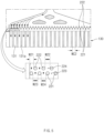
- FIG. 1 is a side view illustrating an example of an electrolysis cell according to an embodiment of the present invention.
- FIG. 2 is a plan view illustrating an example of a passage plate for an electrolysis cell according to a first embodiment of the present invention.
- FIG. 3 is an enlarged plan view illustrating a portion of a supply-side passage part of the passage plate for the electrolysis cell according to the first embodiment of the present invention.
- a passage plate 100 for an electrolysis cell is a passage plate 100 for an electrolysis cell, which faces an electrode E that causes an electrochemical reduction reaction, and includes a supply-side passage part 120 that supplies a raw material fluid, and a channel part 130 in which a plurality of channels 131 through which the supplied raw material fluid flows are provided.
- the passage plate 100 for the electrolysis cell according to the first embodiment of the present invention may include a manifold inlet 110, a discharge-side passage part 140, and a manifold outlet 150.
- a branch passage 123 which is branched into a plurality of passages (hereinafter referred to as a plurality of branch passages 123) through which a raw material fluid is supplied, may be provided in the supply-side passage part 120.
- the raw material fluid may include a carbon dioxide (CO 2 ) and an electrolyte.
- the electrolyte may include water (H 2 O).
- the supply-side passage part 120 may be provided with a plurality of passage blocks 121, and the plurality of branch passages 123 may be branched through the plurality of passage blocks 121. That is, the plurality of branch passages 123 into which a passage that is a passage for supplying the raw material fluid is branched through the plurality of passage blocks 121 may be provided.
- Respective widths W1 and W2 of the plurality of branch passages 123 may be uniform.
- the term "uniform" means that a difference between the widths W1 and W2 of the plurality of branch passages 123 is constant. That is, the widths W1 and W2 of the plurality of branch passages 123 of the supply-side passage part 120 may be the same as each other.
- the width W1 of each of the branch passages 123 disposed at both side portions of the supply-side passage part 120 may be provided to be the same as the width W2 of each of the other branch passages 123 of the supply-side passage part 120.
- a recessed groove 120a that is recessed inward from each of both the side portions of the supply-side passage part 120 may be defined so that the width W1 of each of the branch passages 123 disposed at both the side portions of the supply-side passage part 120 is the same as the width W12 of each of the other branch passages 123 of the supply-side passage part 120.
- the plurality of branch passages 123 may be a passage portion facing the channel part 130.
- Each of the widths W1 and W2 of the plurality of branch passages 123, which are branched through the plurality of passage blocks 121, of the supply-side passage part 120 may be, for example, 0.25 mm to 1 mm.
- the number of the plurality of branch passages 123 of the supply-side passage part 120 may correspond to the number of the plurality of channels 131.
- Positions of the plurality of branch passages 123 of the supply-side passage part 120 and positions of the plurality of channels 131 of the channel part 130 may be provided to correspond to each other. That is, for example, referring to FIG. 2 , the plurality of branch passages 123 may be vertically collinear with the plurality of channels 131, respectively.
- Each of the plurality of passage blocks 121 may have, for example, a cross-section having a circular or non-circular shape.
- each of the plurality of passage blocks 121 may have, for a specific example, a circular cross-section.
- the channel part 130 may have one side portion that is connected to the supply-side passage part 120, and the plurality of channels 131 through which a carbon dioxide and an electrolyte that are a raw material fluid to be supplied flow may be provided.
- the channel part 130 faces an electrode E and the plurality of channels 131 are provided on a surface, which faces the electrode E, of the channel part 130, the raw material fluid flowing through the plurality of channels 131 is in contact with the electrode E, and an electrochemical reaction occurs in the electrode E.
- the plurality of channels 131 may be provided in the form of straight lines so that the raw material fluid flows in a straight-line direction from one side, at which the supply-side passage part 120 is disposed, to the other side.
- a plurality of channel protrusions 131a may be provided in the form of straight lines so that the channel 131 is provided in the form of a straight line. That is, the channel protrusions 131a may protrude in a direction of the electrode E and, referring to FIG. 2 , extend vertically so that the channel 131 that is a passage through which a fluid vertically flows is provided.
- the channel 131 may have a width WC1 that is greater than each of the widths W1 and W2 of the plurality of branch passages 123 of the supply-side passage part 120.
- the width WC1 of the channel 131 may be, for example, 0.5 mm to 2 mm.
- the channel part 130 may have an area of, for example, 100 cm 2 or greater.
- the manifold inlet 110 may be connected to the supply-side passage part 120, and the raw material fluid may flow thereinto.
- the supply-side passage part 120 may supply the raw material fluid flowing from the manifold inlet 110.
- the manifold inlet 110 may include one inflow hole.
- the discharge-side passage part 140 may be connected to the other side portion of the channel part 130 to provide a plurality of passages through which reactants are discharged.
- discharge-side passage part 140 may be provided with a discharge-side passage block 141 through which a plurality of passages are branched.
- the discharge-side passage part 140 may have a shape corresponding to a shape of the supply-side passage part 120. That is, a branching shape of the passages of the discharge-side passage part 140 may be the same as a branching shape of the passages of the supply-side passage part 120.
- the manifold outlet 150 may be connected to the discharge-side passage part 140 so that the reactants are discharged.
- the reactants may be a carbon monoxide (CO), ethylene (C 2 H 4 ), or the like.
- the manifold outlet 150 may include one discharge hole.
- the passage plate 100 for the electrolysis cell is the passage plate 100 for the electrolysis cell which faces the electrode E, and the supply-side passage part 120 in which the branch passage 123, which is branched into the plurality of passages through which the raw material fluid is supplied, is provided, may provide the branch passages 123 that are branched through the plurality of passage blocks 121 so as to have uniform widths. Accordingly, the raw material fluid may be supplied so as to uniformly flow to the plurality of channels 131 of the channel part 130 through which the raw material fluid flows. Accordingly, fluid flow of the reactants is improved to improve the material transfer properties necessary for an electrochemical reaction so that the performance efficiency is optimized, and local deterioration is prevented to improve the durability.
- FIG. 4 is a plan view illustrating an example of a passage plate for an electrolysis cell according to the second embodiment of the present invention.
- FIG. 5 is an enlarged plan view illustrating a portion of a supply-side passage part of the passage plate for the electrolysis cell according to the second embodiment of the present invention.
- a passage plate 200 for an electrolysis cell according to the second embodiment of the present invention is a passage plate for an electrolysis cell, which faces an electrode E that causes an electrochemical reduction reaction, and includes a supply-side passage part 220 that supplies a raw material fluid, and a channel part 130 in which a plurality of channels 131 through which the supplied raw material fluid flows are provided.
- the passage plate 200 for the electrolysis cell according to the second embodiment of the present invention may include a manifold inlet 110, a discharge-side passage part 240, and a manifold outlet 150.
- the passage plate 200 for the electrolysis cell according to an embodiment of the present invention is different in terms of a shape of passages branched through passage blocks 221 and 222 in the supply-side passage part 220, when compared to the passage plate for the electrolysis cell according to the first embodiment described above.
- this embodiment will be described by omitting or simply describing the content in common with the embodiment described above and focusing on differences.
- a plurality of branch passages 223 through which a raw material fluid is supplied may be provided in the supply-side passage part 220.
- the raw material fluid may include a carbon dioxide (CO 2 ) and an electrolyte.
- the electrolyte may include water (H 2 O).
- the supply-side passage part 220 may be provided with the plurality of passage blocks 221 and 222, and the plurality of branch passages 223 may be branched through the plurality of passage blocks 221 and 222.
- respective widths W23 and W24 of the plurality of branch passages 223 may be uniform. That is, the widths W23 and W24 of the plurality of branch passages 223 of the supply-side passage part 220 may be the same as each other.
- the plurality of branch passages 223 may be a passage portion facing the channel part 130.
- Each of the plurality of passage blocks 221 and 222 may have, for example, a cross-section having a circular or non-circular shape.
- each of the plurality of passage blocks 221 and 222 may have, for a specific example, a circular cross-section.
- the plurality of passage blocks 221 and 222 may be arranged in a plurality of rows.
- the plurality of passage blocks 221 and 222 arranged in the plurality of rows may be disposed to be misaligned between the rows. Accordingly, as the plurality of passage blocks 221 and 222 are arranged in the plurality of rows and disposed to be misaligned between the rows, flow distribution of the fluid may be easier performed.
- the plurality of branch passages 223 may be the branch passages 223 in which the flow is distributed through the passage blocks 221, which are in a row adjacent to the channel part 130, of the passage blocks 221 and 222 arranged in the plurality of rows. That is, the branch passages 223 may be the branch passages 223 in which the flow is finally distributed through the passage blocks 221 disposed in a row, which is the last row of the plurality of rows and is most adjacent to the channel part 130.
- the number of the plurality of branch passages 223 of the supply-side passage part 220 may be provided to be greater than the number of the plurality of channels 131, but the passage plate 200 for the electrolysis cell according to the second embodiment of the present invention is not necessarily limited thereto.
- the plurality of passage blocks 221 and 222 arranged in the plurality of rows may be arranged, for example, in two rows.
- the plurality of passage blocks 221 and 222 arranged in two rows are disposed to be misaligned between the rows, and may be arranged in the form of zigzag.
- distances between the plurality of passage blocks 221 disposed in the first row may be provided to be the same, and distances between the plurality of passage blocks 222 disposed in the second row may be provided to be the same.
- the distances between the plurality of passage blocks 221 disposed in the first row, and the distances between the plurality of passage blocks 222 disposed in the second row may be provided to be the same as each other. Accordingly, it may be easier to uniformly distribute the flow of the fluid.
- respective widths W21 and W22 of passages 224 branched through the plurality of passage blocks 222 disposed in the second row may be the same as each other.
- the width W21 of each of passages disposed in both side portions of the supply-side passage part 220 may be provided to be the same as the width W22 of each of the other passages.
- the channel part 130 may have one side portion that is connected to the supply-side passage part 220, and the plurality of channels 131 through which a carbon dioxide and an electrolyte that are a raw material fluid to be supplied flow may be provided.
- the channel part 130 faces an electrode E and the plurality of channels 131 are provided on a surface, which faces the electrode E, of the channel part 130, the raw material fluid flowing through the plurality of channels 131 is in contact with the electrode E, and an electrochemical reaction occurs in the electrode E.
- the plurality of channels 131 may be provided in the form of straight lines so that the raw material fluid flows in a straight-line direction from one side, at which the supply-side passage part 220 is disposed, to the other side.
- the channel 131 may have a width WC2 that is greater than each of the widths W23 and W24 of the plurality of branch passages 223 of the supply-side passage part 220.
- the manifold inlet 110 may be connected to the supply-side passage part 220, and the raw material fluid may flow thereinto.
- the supply-side passage part 220 may supply the raw material fluid flowing from the manifold inlet 110.
- the manifold inlet 110 may include one inflow hole.
- the discharge-side passage part 240 may be connected to the other side portion of the channel part 130 to provide a plurality of passages through which reactants are discharged.
- the discharge-side passage part 240 may have a shape corresponding to a shape of the supply-side passage part 220.
- the manifold outlet 150 may be connected to the discharge-side passage part 240 so that the reactants are discharged.
- the reactants may be a carbon monoxide (CO), ethylene (C 2 H 4 ), or the like.
- the manifold outlet 150 may include one discharge hole.
- FIG. 6 is a plan view illustrating an example of the passage plate for the electrolysis cell according to the third embodiment of the present invention.
- FIG. 7 is an enlarged plan view illustrating a portion of a supply-side passage part of the passage plate for the electrolysis cell according to the third embodiment of the present invention.
- a passage plate 300 for an electrolysis cell is the passage plate 300 for the electrolysis cell, which faces an electrode E that causes an electrochemical reduction reaction, and includes a supply-side passage part 320 that supplies a raw material fluid, and a channel part 130 in which a plurality of channels 131 through which the supplied raw material fluid flows are provided.
- the passage plate 300 for the electrolysis cell according to the third embodiment of the present invention may include a manifold inlet 110, a discharge-side passage part 340, and a manifold outlet 150.
- the passage plate 300 for the electrolysis cell according to the third embodiment of the present invention is different in terms of a shape of passages branched through a passage block 321 in the supply-side passage part 320, when compared to the passage plates for the electrolysis cell according to the first and second embodiments described above.
- this embodiment will be described by omitting or simply describing the content in common with the embodiments described above and focusing on differences.
- a plurality of branch passages 323 through which a raw material fluid is supplied may be provided in the supply-side passage part 320.
- the raw material fluid may include a carbon dioxide (CO 2 ) and an electrolyte.
- the electrolyte may include water (H 2 O).
- the supply-side passage part 320 may be provided with a plurality of passage blocks 321, and the plurality of branch passages 323 may be branched through the plurality of passage blocks 321.
- respective widths W31 and W32 of the plurality of branch passages 323 may be uniform. That is, the widths W31 and W32 of the plurality of branch passages 323 of the supply-side passage part 320 may be the same as each other.
- a recessed groove 320a that is recessed inward from each of both side portions of the supply-side passage part 320 may be defined so that the width W31 of each of the branch passages 323 disposed at both the side portions of the supply-side passage part 320 is the same as the width W2 of each of the other branch passages 323 of the supply-side passage part 320.
- the plurality of branch passages 323 may be a passage portion facing the channel part 130.
- Each of the plurality of passage blocks 321 may have, for example, a cross-section having a circular or non-circular shape.
- each of the plurality of passage blocks 321 may have, for a specific example, a cross-section having a rhombus shape among non-circular shapes.
- the channel part 130 may have one side portion that is connected to the supply-side passage part 320, and the plurality of channels 131 through which a carbon dioxide and an electrolyte that are a raw material fluid to be supplied flow may be provided.
- the channel part 130 faces an electrode E and the plurality of channels 131 are provided on a surface, which faces the electrode E, of the channel part 130, the raw material fluid flowing through the plurality of channels 131 is in contact with the electrode E, and an electrochemical reaction occurs in the electrode E.
- the plurality of channels 131 may be provided in the form of straight lines so that the raw material fluid flows in a straight-line direction from one side, at which the supply-side passage part 320 is disposed, to the other side.
- the channel part 130 may have a width WC3 that is greater or less than each of the widths W31 and W32 of the plurality of branch passages 323 of the supply-side passage part 320, but the passage plate 300 for the electrolysis cell according to the third embodiment of the present invention is not necessarily limited thereto.
- the manifold inlet 110 may be connected to the supply-side passage part 320, and the raw material fluid may flow thereinto.
- the supply-side passage part 320 may supply the raw material fluid flowing from the manifold inlet 110.
- the manifold inlet 110 may include one inflow hole.
- the discharge-side passage part 340 may be connected to the other side portion of the channel part 130 to provide a plurality of passages through which reactants are discharged.
- the discharge-side passage part 340 may have a shape corresponding to a shape of the supply-side passage part 320. That is, a passage shape of the discharge-side passage part 340 may be the same as a passage shape of the supply-side passage part 320.
- the manifold outlet 150 may be connected to the discharge-side passage part 340 so that the reactants are discharged.
- the reactants may be a carbon monoxide (CO), ethylene (C 2 H 4 ), or the like.
- the manifold outlet 150 may include one discharge hole.
- an electrolysis cell 1000 includes a passage plate 100 and an electrode E facing the passage plate 100.
- the passage plate 100 is the passage plate 100 for the electrolysis cell, which faces the electrode E that causes an electrochemical reduction reaction, and includes a supply-side passage part 120 that supplies a raw material fluid, and a channel part 130 in which a plurality of channels 131 through which the supplied raw material fluid flows are provided.
- the passage plate 100 may include a manifold inlet 110, a discharge-side passage part 140, and a manifold outlet 150.
- the electrolysis cell 1000 according to an embodiment of the present invention may further include an ion exchange membrane I.
- the electrolysis cell 1000 according to an embodiment of the present invention relates to the electrolysis cell 1000 including the passage plate for the electrolysis cell according to the first, second, or third embodiment described above.
- this embodiment will be described by omitting or simply describing the content in common with the embodiments of the passage plates for the electrolysis cell according to the first to third embodiments described above and focusing on differences.
- the electrode E may face the passage plate 100 to cause an electrochemical reduction reaction.
- the electrode E may electrolyze, for example, a carbon dioxide (CO 2 ) into a carbon monoxide (CO), ethylene (C 2 H 4 ), or the like.
- the electrode E may include an anode A and a cathode C.
- a plurality of branch passages 123 through which a raw material fluid is supplied may be provided in the supply-side passage part 120.
- the raw material fluid may include a carbon dioxide (CO 2 ) and an electrolyte.
- the electrolyte may include water (H 2 O).
- the supply-side passage part 120 may be provided with a plurality of passage blocks 121, and the plurality of branch passages 123 may be branched through the plurality of passage blocks 121.
- respective widths W1 and W2 of the plurality of branch passages 123 may be uniform. That is, the widths W1 and W2 of the plurality of branch passages 123 of the supply-side passage part 120 may be the same as each other.
- the plurality of branch passages 123 may be a passage portion facing the channel part 130.
- the channel part 130 may have one side portion that is connected to the supply-side passage part 120, and the plurality of channels 131 through which a carbon dioxide and an electrolyte that are a raw material fluid to be supplied flow may be provided.
- the channel part 130 faces an electrode E and the plurality of channels 131 are provided on a surface, which faces the electrode E, of the channel part 130, the raw material fluid flowing through the plurality of channels 131 is in contact with the electrode E, and an electrochemical reaction occurs in the electrode E.
- the channel part 130 may have an area of, for example, 100 cm 2 or greater.
- the electrolysis cell 1000 according to an embodiment of the present invention may have an active area of 100 cm 2 or greater.
- passage plate 100 may be provided in plurality, and the plurality of passage plates 100 may face the anode A and the cathode C, respectively.
- the plurality of passage plates 100 may include a first passage plate P1 facing the anode A, and a second passage plate P2 facing the cathode C.
- each of the passage plates 100, 200 and 300 for the electrolysis cell according to the first to third embodiments described above may include at least one of the first passage plate P1 or the second passage plate P2.
- each of the passage plates 100, 200 and 300 for the electrolysis cell according to the first to third embodiments described above may be the first passage plate P1, but the present invention is not necessarily limited thereto.
- Each of the passage plates 100, 200 and 300 may be the second passage plate P2, or the first passage plate P1 and the second passage plate P2. (See FIGS. 2 , 4 , and 6 .)
- the ion exchange membrane (IEM) I may be disposed between the anode A and the cathode C.
- ions may move between the anode A and the cathode C through the ion exchange membrane I.
- the first passage plate P1, the anode A, the ion exchange membrane I, the cathode C, and the second passage plate P2 may be stacked in sequence.
- a passage plate for an electrolysis cell that electrolyzes a carbon dioxide (CO 2 ) through an electrochemical reduction reaction was manufactured.
- the passage plate was provided to face an electrode in which the electrochemical reduction reaction occurs.
- the passage plate was manufactured to include a supply-side passage part, in which a passage for supplying a carbon dioxide and an electrolyte, which is branched into a plurality of branch passages through a plurality of passage blocks, is provided, and a channel part, which has one side portion connected to the supply-side passage part and in which a plurality of channels through which the supplied carbon dioxide and electrolyte flow are provided.
- the plurality of branch passages were manufactured so that respective widths thereof are uniform.
- the passage plate was manufactured to further include a manifold inlet, which is connected to the supply-side passage part and into which the carbon dioxide and the electrolyte flow, a discharge-side passage part, which is connected to the other side portion of the channel part and in which a plurality of channels through which reactants are discharged, and a manifold outlet connected to the discharge-side passage part.
- Each of the passage blocks was manufactured to have a circular cross-section, and the plurality of branch passages of the supply-side passage part were manufactured so that the number and positions thereof correspond to the number and positions of the plurality of channels of the channel part.
- a passage plate for an electrolysis cell was manufactured to be the same as Manufacturing Example 1, except that a plurality of passage blocks are provided in two rows, the passage blocks are disposed to be misaligned between the rows, and the number of branch passages of a supply-side passage part is provided to be greater than the number of channels of a channel part.
- a passage plate for an electrolysis cell was manufactured to be the same as Manufacturing Example 1, except that a cross-section of a passage block has a rhombus shape, the number of branch passages of a supply-side passage part is provided to be less than the number of channels of a channel part, and a recessed groove that is recessed inward from each of both side portions of the supply-side passage part is defined so that a width of each of branch passages disposed at both the side portions of the supply-side passage part is the same as a width of each of the other branch passages of the supply-side passage part.
- a passage plate for an electrolysis cell was manufactured to be the same as Manufacturing Example 1, except that a cross-section of a passage block has a rhombus shape, the number of branch passages of a supply-side passage part is provided to be less than the number of channels of a channel part, respective widths of the plurality of branch passages are provided to be nonuniform, and a width of each of the branch passages disposed at both side portions of the supply-side passage part is provided to be greater than a width of each of the other branch passages of the supply-side passage part.
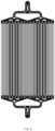
- FIG. 8 is an image illustrating flow velocity distribution in the passage plate for the electrolysis cell according to Comparison Example 1.
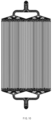
- FIG. 9 is an image illustrating flow velocity distribution in the passage plate for the electrolysis cell according to Manufacturing Example 1.
- FIG. 10 is an image illustrating flow velocity distribution in the passage plate for the electrolysis cell according to Manufacturing Example 2.
- FIG. 11 is an image illustrating flow velocity distribution in the passage plate for the electrolysis cell according to Manufacturing Example 3.
- FIGS. 8 to 11 the images show fluid-flow velocity distribution during a process from allowing of a fluid of a carbon dioxide and an electrolyte to flow into a manifold inlet to discharging of the fluid through a discharge-side outlet in the passage plates for the electrolysis cell according to Comparison Example 1 and Manufacturing Examples 1 to 3.
- both side portions are represented by hatched portions in which the flow velocity is remarkably rapid, and the other portions are represented by dark grey portions in which the partial flow velocity is relatively slow. Accordingly, it may be known that the flow velocity between the channels of the channel part is remarkably nonuniform in Comparison Example 1.
- the flow velocity is indicated in light grey to be uniform in both side portions and the other portions.
- the flow velocity between the channels of the channel part is remarkably uniform in Manufacturing Examples 1 to 3.
- the shapes and arrangement of the passage blocks that branch the passages are nonuniform in Comparison Example 1 so that the flow rate is biased to some channels disposed at both edges, and it may be known that the shapes and arrangement of the passage blocks that branch the passages are uniform in Manufacturing Examples 1 to 3 so that the flow rate in all the channels is uniform without the flow rate biased to some channels.
- Comparison Example 1 has a deviation of 8.45 which is great, whereas Manufacturing Examples 1, 2, and 3 show deviations of 2.99, 2.96, and 4.40, respectively, which are remarkably small.
- Manufacturing Examples 1 and 2 may reduce the flow rate deviation between the channels by 74%, and Manufacturing Example 3 may improve the flow rate deviation by 48%.
- the passage plates for the electrolysis cell according to Manufacturing Examples 1 to 3 may have been remarkably improved in terms of flow distribution of reactants and products necessary for electrolysis of a carbon dioxide.
Landscapes
- Chemical & Material Sciences (AREA)
- Organic Chemistry (AREA)
- Engineering & Computer Science (AREA)
- Chemical Kinetics & Catalysis (AREA)
- Electrochemistry (AREA)
- Materials Engineering (AREA)
- Metallurgy (AREA)
- Inorganic Chemistry (AREA)
- Electrolytic Production Of Non-Metals, Compounds, Apparatuses Therefor (AREA)
Abstract
Description
- The present application claims the benefit of the priority of
Korean Patent Application Nos. 10-2022-0110644, filed on September 1, 2022 10-2023-0115367, filed on August 31, 2023 - The present invention relates to a passage plate for an electrolysis cell, and an electrolysis cell including the same.
- Cells for electrolyzing carbon dioxides (CO2) to convert the same into useful resources such as CO or ethylene need to secure active areas to a certain level or higher through an increase in area in addition to stacking for scale-up.
- Design of a passage structure capable of uniformly supplying a CO2 gas and an electrolyte to the entire active area is important in design of large-area cells.
- Typical research on CO2 electrochemical conversion technology is mostly focused on securing performance of small-sized cells, and when structures of these small-sized cells are applied as they are to increase the active areas of the cells, efficiency of the large-area cells may be deteriorated compared to the small-sized cells.
- One aspect of the present invention is to provide a passage plate for an electrolysis cell, capable of improving material transfer properties and cell performance efficiency, and an electrolysis cell including the passage plate.
- A passage plate for an electrolysis cell according to an embodiment of the present invention is a passage plate for an electrolysis cell, which faces an electrode that causes an electrochemical reaction, and may include a supply-side passage part, in which a branch passage, which is branched into a plurality of passages through which a raw material fluid is supplied, is provided, and a channel part, which has one side portion connected to the supply-side passage part and in which a plurality of channels through which the supplied raw material fluid flows are provided, wherein the supply-side passage part includes a plurality of passage blocks, the plurality of branch passages are branched through the plurality of passage blocks, and respective widths of the plurality of branch passages are uniform.
- In addition, an electrolysis cell according to an embodiment of the present invention may include the passage plate for the electrolysis cell according to an embodiment of the present invention, and the electrode facing the passage plate.
- According to the present invention, in the passage plate for the electrolysis cell that faces the electrode, in the supply-side passage part in which the branch passage, which is branched into the plurality of passages through which the raw material fluid is supplied, is provided, the passages may be branched through the plurality of passage blocks so as to have the uniform widths. Accordingly, the raw material fluid may be supplied so as to uniformly flow to the plurality of channels of the channel part through which the raw material fluid flows.
- Accordingly, the flow of the reactant fluid is improved to improve the material transfer properties necessary for the electrochemical reaction so that the performance efficiency is optimized, and the local deterioration is prevented to improve the durability.
-
-
FIG. 1 is a side view illustrating an example of an electrolysis cell according to an embodiment of the present invention. -
FIG. 2 is a plan view illustrating an example of a passage plate for an electrolysis cell according to a first embodiment of the present invention. -
FIG. 3 is an enlarged plan view illustrating a portion of a supply-side passage part of the passage plate for the electrolysis cell according to the first embodiment of the present invention. -
FIG. 4 is a plan view illustrating an example of a passage plate for an electrolysis cell according to a second embodiment of the present invention. -
FIG. 5 is an enlarged plan view illustrating a portion of a supply-side passage part of the passage plate for the electrolysis cell according to the second embodiment of the present invention. -
FIG. 6 is a plan view illustrating an example of a passage plate for an electrolysis cell according to a third embodiment of the present invention. -
FIG. 7 is an enlarged plan view illustrating a portion of a supply-side passage part of the passage plate for the electrolysis cell according to the third embodiment of the present invention. -
FIG. 8 is an image illustrating flow velocity distribution in a passage plate for an electrolysis cell according to Comparison Example 1. -
FIG. 9 is an image illustrating flow velocity distribution in a passage plate for an electrolysis cell according to Manufacturing Example 1. -
FIG. 10 is an image illustrating flow velocity distribution in a passage plate for an electrolysis cell according to Manufacturing Example 2. -
FIG. 11 is an image illustrating flow velocity distribution in a passage plate for an electrolysis cell according to Manufacturing Example 3. - The purpose, specified advantages, and novel features of the present invention will be clarified through following embodiments described with reference to the accompanying drawings. Note that like elements are designated by like reference numerals as far as possible even if they are shown in different drawings. The present invention may be embodied in different forms and should not be construed as limited to the embodiments set forth herein. Moreover, in the following description of the present invention, detailed descriptions of the related well-known art that may unnecessarily obscure subject matters of the present invention will be ruled out.
-
FIG. 1 is a side view illustrating an example of an electrolysis cell according to an embodiment of the present invention.FIG. 2 is a plan view illustrating an example of a passage plate for an electrolysis cell according to a first embodiment of the present invention.FIG. 3 is an enlarged plan view illustrating a portion of a supply-side passage part of the passage plate for the electrolysis cell according to the first embodiment of the present invention. - Referring
FIGS. 1 to 3 , apassage plate 100 for an electrolysis cell according to the first embodiment of the present invention is apassage plate 100 for an electrolysis cell, which faces an electrode E that causes an electrochemical reduction reaction, and includes a supply-side passage part 120 that supplies a raw material fluid, and achannel part 130 in which a plurality ofchannels 131 through which the supplied raw material fluid flows are provided. In addition, thepassage plate 100 for the electrolysis cell according to the first embodiment of the present invention may include amanifold inlet 110, a discharge-side passage part 140, and amanifold outlet 150. - In more detail, in the
passage plate 100 for the electrolysis cell according to the first embodiment of the present invention, abranch passage 123, which is branched into a plurality of passages (hereinafter referred to as a plurality of branch passages 123) through which a raw material fluid is supplied, may be provided in the supply-side passage part 120. Here, the raw material fluid may include a carbon dioxide (CO2) and an electrolyte. Here, the electrolyte may include water (H2O). - The supply-
side passage part 120 may be provided with a plurality ofpassage blocks 121, and the plurality ofbranch passages 123 may be branched through the plurality ofpassage blocks 121. That is, the plurality ofbranch passages 123 into which a passage that is a passage for supplying the raw material fluid is branched through the plurality ofpassage blocks 121 may be provided. - Respective widths W1 and W2 of the plurality of
branch passages 123 may be uniform. Here, the term "uniform" means that a difference between the widths W1 and W2 of the plurality ofbranch passages 123 is constant. That is, the widths W1 and W2 of the plurality ofbranch passages 123 of the supply-side passage part 120 may be the same as each other. In particular, the width W1 of each of thebranch passages 123 disposed at both side portions of the supply-side passage part 120 may be provided to be the same as the width W2 of each of theother branch passages 123 of the supply-side passage part 120. Here, arecessed groove 120a that is recessed inward from each of both the side portions of the supply-side passage part 120 may be defined so that the width W1 of each of thebranch passages 123 disposed at both the side portions of the supply-side passage part 120 is the same as the width W12 of each of theother branch passages 123 of the supply-side passage part 120. - Here, the plurality of
branch passages 123 may be a passage portion facing thechannel part 130. - Each of the widths W1 and W2 of the plurality of
branch passages 123, which are branched through the plurality ofpassage blocks 121, of the supply-side passage part 120 may be, for example, 0.25 mm to 1 mm. - The number of the plurality of
branch passages 123 of the supply-side passage part 120 may correspond to the number of the plurality ofchannels 131. - Positions of the plurality of
branch passages 123 of the supply-side passage part 120 and positions of the plurality ofchannels 131 of thechannel part 130 may be provided to correspond to each other. That is, for example, referring toFIG. 2 , the plurality ofbranch passages 123 may be vertically collinear with the plurality ofchannels 131, respectively. - Each of the plurality of
passage blocks 121 may have, for example, a cross-section having a circular or non-circular shape. Here, each of the plurality ofpassage blocks 121 may have, for a specific example, a circular cross-section. - The
channel part 130 may have one side portion that is connected to the supply-side passage part 120, and the plurality ofchannels 131 through which a carbon dioxide and an electrolyte that are a raw material fluid to be supplied flow may be provided. - As the
channel part 130 faces an electrode E and the plurality ofchannels 131 are provided on a surface, which faces the electrode E, of thechannel part 130, the raw material fluid flowing through the plurality ofchannels 131 is in contact with the electrode E, and an electrochemical reaction occurs in the electrode E. - In the
channel part 130, the plurality ofchannels 131 may be provided in the form of straight lines so that the raw material fluid flows in a straight-line direction from one side, at which the supply-side passage part 120 is disposed, to the other side. - Here, a plurality of
channel protrusions 131a may be provided in the form of straight lines so that thechannel 131 is provided in the form of a straight line. That is, thechannel protrusions 131a may protrude in a direction of the electrode E and, referring toFIG. 2 , extend vertically so that thechannel 131 that is a passage through which a fluid vertically flows is provided. - In addition, for example, the
channel 131 may have a width WC1 that is greater than each of the widths W1 and W2 of the plurality ofbranch passages 123 of the supply-side passage part 120. - The width WC1 of the
channel 131 may be, for example, 0.5 mm to 2 mm. - The
channel part 130 may have an area of, for example, 100 cm2 or greater. - The
manifold inlet 110 may be connected to the supply-side passage part 120, and the raw material fluid may flow thereinto. Here, the supply-side passage part 120 may supply the raw material fluid flowing from themanifold inlet 110. - The
manifold inlet 110 may include one inflow hole. - The discharge-
side passage part 140 may be connected to the other side portion of thechannel part 130 to provide a plurality of passages through which reactants are discharged. - In addition, the discharge-
side passage part 140 may be provided with a discharge-side passage block 141 through which a plurality of passages are branched. - In addition, the discharge-
side passage part 140 may have a shape corresponding to a shape of the supply-side passage part 120. That is, a branching shape of the passages of the discharge-side passage part 140 may be the same as a branching shape of the passages of the supply-side passage part 120. - The
manifold outlet 150 may be connected to the discharge-side passage part 140 so that the reactants are discharged. - Here, the reactants may be a carbon monoxide (CO), ethylene (C2H4), or the like.
- The
manifold outlet 150 may include one discharge hole. - The
passage plate 100 for the electrolysis cell according to the first embodiment of the present invention configured as above is thepassage plate 100 for the electrolysis cell which faces the electrode E, and the supply-side passage part 120 in which thebranch passage 123, which is branched into the plurality of passages through which the raw material fluid is supplied, is provided, may provide thebranch passages 123 that are branched through the plurality of passage blocks 121 so as to have uniform widths. Accordingly, the raw material fluid may be supplied so as to uniformly flow to the plurality ofchannels 131 of thechannel part 130 through which the raw material fluid flows. Accordingly, fluid flow of the reactants is improved to improve the material transfer properties necessary for an electrochemical reaction so that the performance efficiency is optimized, and local deterioration is prevented to improve the durability. - Hereinafter, a passage plate for an electrolysis cell according to a second embodiment of the present invention will be described.
-
FIG. 4 is a plan view illustrating an example of a passage plate for an electrolysis cell according to the second embodiment of the present invention.FIG. 5 is an enlarged plan view illustrating a portion of a supply-side passage part of the passage plate for the electrolysis cell according to the second embodiment of the present invention. - Referring
FIGS. 1 ,4 , and5 , apassage plate 200 for an electrolysis cell according to the second embodiment of the present invention is a passage plate for an electrolysis cell, which faces an electrode E that causes an electrochemical reduction reaction, and includes a supply-side passage part 220 that supplies a raw material fluid, and achannel part 130 in which a plurality ofchannels 131 through which the supplied raw material fluid flows are provided. In addition, thepassage plate 200 for the electrolysis cell according to the second embodiment of the present invention may include amanifold inlet 110, a discharge-side passage part 240, and amanifold outlet 150. - The
passage plate 200 for the electrolysis cell according to an embodiment of the present invention is different in terms of a shape of passages branched through passage blocks 221 and 222 in the supply-side passage part 220, when compared to the passage plate for the electrolysis cell according to the first embodiment described above. Thus, this embodiment will be described by omitting or simply describing the content in common with the embodiment described above and focusing on differences. - In more detail, in the
passage plate 200 for the electrolysis cell according to the second embodiment of the present invention, a plurality ofbranch passages 223 through which a raw material fluid is supplied may be provided in the supply-side passage part 220. Here, the raw material fluid may include a carbon dioxide (CO2) and an electrolyte. Here, the electrolyte may include water (H2O). - The supply-
side passage part 220 may be provided with the plurality of passage blocks 221 and 222, and the plurality ofbranch passages 223 may be branched through the plurality of passage blocks 221 and 222. Here, respective widths W23 and W24 of the plurality ofbranch passages 223 may be uniform. That is, the widths W23 and W24 of the plurality ofbranch passages 223 of the supply-side passage part 220 may be the same as each other. Here, the plurality ofbranch passages 223 may be a passage portion facing thechannel part 130. - Each of the plurality of passage blocks 221 and 222 may have, for example, a cross-section having a circular or non-circular shape. Here, each of the plurality of passage blocks 221 and 222 may have, for a specific example, a circular cross-section.
- In addition, the plurality of passage blocks 221 and 222 may be arranged in a plurality of rows. Here, the plurality of passage blocks 221 and 222 arranged in the plurality of rows may be disposed to be misaligned between the rows. Accordingly, as the plurality of passage blocks 221 and 222 are arranged in the plurality of rows and disposed to be misaligned between the rows, flow distribution of the fluid may be easier performed.
- Here, the plurality of
branch passages 223 may be thebranch passages 223 in which the flow is distributed through the passage blocks 221, which are in a row adjacent to thechannel part 130, of the passage blocks 221 and 222 arranged in the plurality of rows. That is, thebranch passages 223 may be thebranch passages 223 in which the flow is finally distributed through the passage blocks 221 disposed in a row, which is the last row of the plurality of rows and is most adjacent to thechannel part 130. For example, the number of the plurality ofbranch passages 223 of the supply-side passage part 220 may be provided to be greater than the number of the plurality ofchannels 131, but thepassage plate 200 for the electrolysis cell according to the second embodiment of the present invention is not necessarily limited thereto. - In addition, the plurality of passage blocks 221 and 222 arranged in the plurality of rows may be arranged, for example, in two rows. Here, the plurality of passage blocks 221 and 222 arranged in two rows are disposed to be misaligned between the rows, and may be arranged in the form of zigzag.
- When the plurality of passage blocks 221 and 222 are arranged in two rows, and when a row close to the
channel part 130 is referred to as the first row, and a row close to themanifold inlet 110 is referred to as the second row, distances between the plurality of passage blocks 221 disposed in the first row may be provided to be the same, and distances between the plurality of passage blocks 222 disposed in the second row may be provided to be the same. Here, the distances between the plurality of passage blocks 221 disposed in the first row, and the distances between the plurality of passage blocks 222 disposed in the second row may be provided to be the same as each other. Accordingly, it may be easier to uniformly distribute the flow of the fluid. - Here, respective widths W21 and W22 of
passages 224 branched through the plurality of passage blocks 222 disposed in the second row may be the same as each other. In addition, in thepassages 224 branched through the plurality of passage blocks 222 disposed in the second row, the width W21 of each of passages disposed in both side portions of the supply-side passage part 220 may be provided to be the same as the width W22 of each of the other passages. - The
channel part 130 may have one side portion that is connected to the supply-side passage part 220, and the plurality ofchannels 131 through which a carbon dioxide and an electrolyte that are a raw material fluid to be supplied flow may be provided. - As the
channel part 130 faces an electrode E and the plurality ofchannels 131 are provided on a surface, which faces the electrode E, of thechannel part 130, the raw material fluid flowing through the plurality ofchannels 131 is in contact with the electrode E, and an electrochemical reaction occurs in the electrode E. - In the
channel part 130, the plurality ofchannels 131 may be provided in the form of straight lines so that the raw material fluid flows in a straight-line direction from one side, at which the supply-side passage part 220 is disposed, to the other side. - In addition, for example, the
channel 131 may have a width WC2 that is greater than each of the widths W23 and W24 of the plurality ofbranch passages 223 of the supply-side passage part 220. - The
manifold inlet 110 may be connected to the supply-side passage part 220, and the raw material fluid may flow thereinto. Here, the supply-side passage part 220 may supply the raw material fluid flowing from themanifold inlet 110. - The
manifold inlet 110 may include one inflow hole. - The discharge-
side passage part 240 may be connected to the other side portion of thechannel part 130 to provide a plurality of passages through which reactants are discharged. - The discharge-
side passage part 240 may have a shape corresponding to a shape of the supply-side passage part 220. - The
manifold outlet 150 may be connected to the discharge-side passage part 240 so that the reactants are discharged. - Here, the reactants may be a carbon monoxide (CO), ethylene (C2H4), or the like.
- The
manifold outlet 150 may include one discharge hole. - Hereinafter, a passage plate for an electrolysis cell according to a third embodiment of the present invention will be described.
-
FIG. 6 is a plan view illustrating an example of the passage plate for the electrolysis cell according to the third embodiment of the present invention.FIG. 7 is an enlarged plan view illustrating a portion of a supply-side passage part of the passage plate for the electrolysis cell according to the third embodiment of the present invention. - Referring
FIGS. 1 ,6 , and7 , apassage plate 300 for an electrolysis cell according to the third embodiment of the present invention is thepassage plate 300 for the electrolysis cell, which faces an electrode E that causes an electrochemical reduction reaction, and includes a supply-side passage part 320 that supplies a raw material fluid, and achannel part 130 in which a plurality ofchannels 131 through which the supplied raw material fluid flows are provided. In addition, thepassage plate 300 for the electrolysis cell according to the third embodiment of the present invention may include amanifold inlet 110, a discharge-side passage part 340, and amanifold outlet 150. - The
passage plate 300 for the electrolysis cell according to the third embodiment of the present invention is different in terms of a shape of passages branched through apassage block 321 in the supply-side passage part 320, when compared to the passage plates for the electrolysis cell according to the first and second embodiments described above. Thus, this embodiment will be described by omitting or simply describing the content in common with the embodiments described above and focusing on differences. - In more detail, in the
passage plate 300 for the electrolysis cell according to the third embodiment of the present invention, a plurality ofbranch passages 323 through which a raw material fluid is supplied may be provided in the supply-side passage part 320. Here, the raw material fluid may include a carbon dioxide (CO2) and an electrolyte. Here, the electrolyte may include water (H2O). - The supply-
side passage part 320 may be provided with a plurality of passage blocks 321, and the plurality ofbranch passages 323 may be branched through the plurality of passage blocks 321. Here, respective widths W31 and W32 of the plurality ofbranch passages 323 may be uniform. That is, the widths W31 and W32 of the plurality ofbranch passages 323 of the supply-side passage part 320 may be the same as each other. Here, a recessed groove 320a that is recessed inward from each of both side portions of the supply-side passage part 320 may be defined so that the width W31 of each of thebranch passages 323 disposed at both the side portions of the supply-side passage part 320 is the same as the width W2 of each of theother branch passages 323 of the supply-side passage part 320. - Here, the plurality of
branch passages 323 may be a passage portion facing thechannel part 130. - Each of the plurality of passage blocks 321 may have, for example, a cross-section having a circular or non-circular shape. Here, each of the plurality of passage blocks 321 may have, for a specific example, a cross-section having a rhombus shape among non-circular shapes.
- The
channel part 130 may have one side portion that is connected to the supply-side passage part 320, and the plurality ofchannels 131 through which a carbon dioxide and an electrolyte that are a raw material fluid to be supplied flow may be provided. - In addition, as the
channel part 130 faces an electrode E and the plurality ofchannels 131 are provided on a surface, which faces the electrode E, of thechannel part 130, the raw material fluid flowing through the plurality ofchannels 131 is in contact with the electrode E, and an electrochemical reaction occurs in the electrode E. - In the
channel part 130, the plurality ofchannels 131 may be provided in the form of straight lines so that the raw material fluid flows in a straight-line direction from one side, at which the supply-side passage part 320 is disposed, to the other side. - In addition, for example, the
channel part 130 may have a width WC3 that is greater or less than each of the widths W31 and W32 of the plurality ofbranch passages 323 of the supply-side passage part 320, but thepassage plate 300 for the electrolysis cell according to the third embodiment of the present invention is not necessarily limited thereto. - The
manifold inlet 110 may be connected to the supply-side passage part 320, and the raw material fluid may flow thereinto. Here, the supply-side passage part 320 may supply the raw material fluid flowing from themanifold inlet 110. - The
manifold inlet 110 may include one inflow hole. - The discharge-
side passage part 340 may be connected to the other side portion of thechannel part 130 to provide a plurality of passages through which reactants are discharged. - In addition, the discharge-
side passage part 340 may have a shape corresponding to a shape of the supply-side passage part 320. That is, a passage shape of the discharge-side passage part 340 may be the same as a passage shape of the supply-side passage part 320. - The
manifold outlet 150 may be connected to the discharge-side passage part 340 so that the reactants are discharged. - Here, the reactants may be a carbon monoxide (CO), ethylene (C2H4), or the like.
- The
manifold outlet 150 may include one discharge hole. - Hereinafter, an electrolysis cell according to an embodiment of the present invention will be described.
- Referring
FIGS. 1 to 3 , anelectrolysis cell 1000 according to an embodiment of the present invention includes apassage plate 100 and an electrode E facing thepassage plate 100. Here, thepassage plate 100 is thepassage plate 100 for the electrolysis cell, which faces the electrode E that causes an electrochemical reduction reaction, and includes a supply-side passage part 120 that supplies a raw material fluid, and achannel part 130 in which a plurality ofchannels 131 through which the supplied raw material fluid flows are provided. In addition, thepassage plate 100 may include amanifold inlet 110, a discharge-side passage part 140, and amanifold outlet 150. Theelectrolysis cell 1000 according to an embodiment of the present invention may further include an ion exchange membrane I. - The
electrolysis cell 1000 according to an embodiment of the present invention relates to theelectrolysis cell 1000 including the passage plate for the electrolysis cell according to the first, second, or third embodiment described above. Thus, this embodiment will be described by omitting or simply describing the content in common with the embodiments of the passage plates for the electrolysis cell according to the first to third embodiments described above and focusing on differences. - In more detail, the electrode E may face the
passage plate 100 to cause an electrochemical reduction reaction. Here, the electrode E may electrolyze, for example, a carbon dioxide (CO2) into a carbon monoxide (CO), ethylene (C2H4), or the like. - The electrode E may include an anode A and a cathode C.
- In the
passage plate 100, a plurality ofbranch passages 123 through which a raw material fluid is supplied may be provided in the supply-side passage part 120. Here, the raw material fluid may include a carbon dioxide (CO2) and an electrolyte. Here, the electrolyte may include water (H2O). The supply-side passage part 120 may be provided with a plurality of passage blocks 121, and the plurality ofbranch passages 123 may be branched through the plurality of passage blocks 121. Here, respective widths W1 and W2 of the plurality ofbranch passages 123 may be uniform. That is, the widths W1 and W2 of the plurality ofbranch passages 123 of the supply-side passage part 120 may be the same as each other. Here, the plurality ofbranch passages 123 may be a passage portion facing thechannel part 130. - The
channel part 130 may have one side portion that is connected to the supply-side passage part 120, and the plurality ofchannels 131 through which a carbon dioxide and an electrolyte that are a raw material fluid to be supplied flow may be provided. In addition, as thechannel part 130 faces an electrode E and the plurality ofchannels 131 are provided on a surface, which faces the electrode E, of thechannel part 130, the raw material fluid flowing through the plurality ofchannels 131 is in contact with the electrode E, and an electrochemical reaction occurs in the electrode E. - The
channel part 130 may have an area of, for example, 100 cm2 or greater. Thus, theelectrolysis cell 1000 according to an embodiment of the present invention may have an active area of 100 cm2 or greater. - In addition, the
passage plate 100 may be provided in plurality, and the plurality ofpassage plates 100 may face the anode A and the cathode C, respectively. - The plurality of
passage plates 100 may include a first passage plate P1 facing the anode A, and a second passage plate P2 facing the cathode C. - Here, each of the
passage plates passage plates passage plates FIGS. 2 ,4 , and6 .) - The ion exchange membrane (IEM) I may be disposed between the anode A and the cathode C. Here, ions may move between the anode A and the cathode C through the ion exchange membrane I.
- In the
electrolysis cell 1000 according to an embodiment of the present invention, the first passage plate P1, the anode A, the ion exchange membrane I, the cathode C, and the second passage plate P2 may be stacked in sequence. - A passage plate for an electrolysis cell that electrolyzes a carbon dioxide (CO2) through an electrochemical reduction reaction was manufactured. The passage plate was provided to face an electrode in which the electrochemical reduction reaction occurs.
- The passage plate was manufactured to include a supply-side passage part, in which a passage for supplying a carbon dioxide and an electrolyte, which is branched into a plurality of branch passages through a plurality of passage blocks, is provided, and a channel part, which has one side portion connected to the supply-side passage part and in which a plurality of channels through which the supplied carbon dioxide and electrolyte flow are provided. Here, the plurality of branch passages were manufactured so that respective widths thereof are uniform.
- The passage plate was manufactured to further include a manifold inlet, which is connected to the supply-side passage part and into which the carbon dioxide and the electrolyte flow, a discharge-side passage part, which is connected to the other side portion of the channel part and in which a plurality of channels through which reactants are discharged, and a manifold outlet connected to the discharge-side passage part.
- Each of the passage blocks was manufactured to have a circular cross-section, and the plurality of branch passages of the supply-side passage part were manufactured so that the number and positions thereof correspond to the number and positions of the plurality of channels of the channel part.
- A passage plate for an electrolysis cell was manufactured to be the same as Manufacturing Example 1, except that a plurality of passage blocks are provided in two rows, the passage blocks are disposed to be misaligned between the rows, and the number of branch passages of a supply-side passage part is provided to be greater than the number of channels of a channel part.
- A passage plate for an electrolysis cell was manufactured to be the same as Manufacturing Example 1, except that a cross-section of a passage block has a rhombus shape, the number of branch passages of a supply-side passage part is provided to be less than the number of channels of a channel part, and a recessed groove that is recessed inward from each of both side portions of the supply-side passage part is defined so that a width of each of branch passages disposed at both the side portions of the supply-side passage part is the same as a width of each of the other branch passages of the supply-side passage part.
- A passage plate for an electrolysis cell was manufactured to be the same as Manufacturing Example 1, except that a cross-section of a passage block has a rhombus shape, the number of branch passages of a supply-side passage part is provided to be less than the number of channels of a channel part, respective widths of the plurality of branch passages are provided to be nonuniform, and a width of each of the branch passages disposed at both side portions of the supply-side passage part is provided to be greater than a width of each of the other branch passages of the supply-side passage part.
-
FIG. 8 is an image illustrating flow velocity distribution in the passage plate for the electrolysis cell according to Comparison Example 1.FIG. 9 is an image illustrating flow velocity distribution in the passage plate for the electrolysis cell according to Manufacturing Example 1.FIG. 10 is an image illustrating flow velocity distribution in the passage plate for the electrolysis cell according to Manufacturing Example 2.FIG. 11 is an image illustrating flow velocity distribution in the passage plate for the electrolysis cell according to Manufacturing Example 3. - In
FIGS. 8 to 11 , the images show fluid-flow velocity distribution during a process from allowing of a fluid of a carbon dioxide and an electrolyte to flow into a manifold inlet to discharging of the fluid through a discharge-side outlet in the passage plates for the electrolysis cell according to Comparison Example 1 and Manufacturing Examples 1 to 3. - In addition, deviations in flow rate of the fluid in a channel part measured in Experimental Example 1 are shown in Table 1 below.
[Table 1] Comparison Example 1 Manufacturing Example 1 Manufacturing Example 2 Manufacturing Example 3 flow rate deviation (%) 8.45 2.99 2.96 4.40 - According to the image of the flow velocity distribution in the channel part of the passage plate according to Comparison Example 1 shown in
FIG. 8 , both side portions are represented by hatched portions in which the flow velocity is remarkably rapid, and the other portions are represented by dark grey portions in which the partial flow velocity is relatively slow. Accordingly, it may be known that the flow velocity between the channels of the channel part is remarkably nonuniform in Comparison Example 1. In contrast, according to the images of the flow velocity distribution in the channel parts of the passage plate according to Manufacturing Example 1 shown inFIG. 9 , the passage plate according to Manufacturing Example 2 shown inFIG. 10 , and the passage plate according to Manufacturing Example 3 shown inFIG. 11 , the flow velocity is indicated in light grey to be uniform in both side portions and the other portions. Accordingly, it may be known that the flow velocity between the channels of the channel part is remarkably uniform in Manufacturing Examples 1 to 3. Thus, it may be known that the shapes and arrangement of the passage blocks that branch the passages are nonuniform in Comparison Example 1 so that the flow rate is biased to some channels disposed at both edges, and it may be known that the shapes and arrangement of the passage blocks that branch the passages are uniform in Manufacturing Examples 1 to 3 so that the flow rate in all the channels is uniform without the flow rate biased to some channels. - In addition, referring to Table 1, it may be known that in the flow rate deviation (%), Comparison Example 1 has a deviation of 8.45 which is great, whereas Manufacturing Examples 1, 2, and 3 show deviations of 2.99, 2.96, and 4.40, respectively, which are remarkably small.
- Thus, compared to Comparison Example 1, Manufacturing Examples 1 and 2 may reduce the flow rate deviation between the channels by 74%, and Manufacturing Example 3 may improve the flow rate deviation by 48%.
- As a result, it may be known that when compared to the passage plate for the electrolysis cell according to Comparison Example 1, the passage plates for the electrolysis cell according to Manufacturing Examples 1 to 3 may have been remarkably improved in terms of flow distribution of reactants and products necessary for electrolysis of a carbon dioxide.
- Although the present invention has been described in detail with reference to the limited embodiments, the embodiments are intended to specifically describe the present invention, and a post-processing apparatus according to the present invention is not limited thereto. The present invention may be variously implemented by those of ordinary skill in the art, to which the present invention pertains, within the technical idea of the present invention.
- Moreover, the specific protective scope of the present invention will be clarified by the accompanying claims.
-
- 100,200,300,500: Passage plate
- 110: Manifold inlet
- 120,220,320: Supply-side passage part
- 121,221,222,321: Passage block
- 123,223,323: Branch passage
- 130: Channel part
- 131: Channel
- 131a: Channel protrusion
- 140,240,340: Discharge-side passage part
- 141,341: Discharge-side passage block
- 150: Manifold outlet
- 320a: Recessed groove
- 1000: Electrolysis cell
- A: Anode
- C: Cathode
- E: Electrode
- I: Ion exchange membrane
- P1: First passage plate
- P2: Second passage plate
Claims (15)
- A passage plate for an electrolysis cell, which faces an electrode configured to cause an electrochemical reaction, the passage plate comprising:a supply-side passage part in which a branch passage, which is branched into a plurality of passages through which a raw material fluid is supplied, is provided; anda channel part which has one side portion connected to the supply-side passage part, and in which a plurality of channels through which the supplied raw material fluid flows are provided,wherein the supply-side passage part comprises a plurality of passage blocks,the plurality of branch passages are branched through the plurality of passage blocks, andrespective widths of the plurality of branch passages are uniform.
- The passage plate of claim 1, wherein the channel part faces the electrode, wherein the plurality of channels are provided on a surface, which faces the electrode, of the channel part so that the raw material fluid flowing through the plurality of channels is in contact with the electrode, and the electrochemical reaction occurs in the electrode.
- The passage plate of claim 1, wherein the number of the plurality of branch passages of the supply-side passage part corresponds to the number of the plurality of channels.
- The passage plate of claim 1, wherein positions of the plurality of branch passages of the supply-side passage part and positions of the plurality of channels of the channel part are provided to correspond to each other.
- The passage plate of claim 1, wherein each of the plurality of passage blocks has a circular cross-section.
- The passage plate of claim 5, wherein the plurality of passage blocks are arranged in a plurality of rows,
wherein the plurality of passage blocks arranged in the plurality of rows are disposed to be misaligned with each other between the rows. - The passage plate of claim 1, wherein each of the plurality of passage blocks has a non-circular cross-section.
- The passage plate of claim 1, wherein a width of each of the branch passages disposed at both side portions of the supply-side passage part is provided to be the same as a width of each of the other passages of the supply-side passage part.
- The passage plate of claim 1, further comprising a manifold inlet which is connected to the supply-side passage part and into which the raw material fluid flows,
wherein the supply-side passage part supplies the raw material fluid flowing from the manifold inlet. - The passage plate of claim 1, wherein further comprising:a discharge-side passage part which is connected to the other side portion of the channel part, and in which a plurality of branches passages through which reactants are discharged are provided; anda manifold outlet connected to the discharge-side passage part.
- The passage plate of claim 10, wherein the discharge-side passage part has a shape corresponding to a shape of the supply-side passage part.
- The passage plate of claim 1, wherein the plurality of channels are provided in the form of straight lines so that the raw material fluid flows in a straight-line direction from one side, at which the supply-side passage part is disposed, to the other side.
- The passage plate of claim 1, wherein the raw material fluid comprises a carbon dioxide (CO2), and an electrolyte comprising water (H2O) so that the carbon dioxide is electrolyzed in the electrode through an electrochemical reduction reaction.
- An electrolysis cell comprising:the passage plate for the electrolysis cell of any one of claims 1 to 13; andan electrode facing the passage plate.
- The electrolysis cell of claim 14, wherein the electrode comprises an anode and a cathode,the passage plate is provided in plurality, and the plurality of passage plates face the anode and the cathode, respectively, andthe electrolysis cell further comprises an ion exchange membrane (IEM) disposed between the anode and the cathode.
Applications Claiming Priority (3)
| Application Number | Priority Date | Filing Date | Title |
|---|---|---|---|
| KR20220110644 | 2022-09-01 | ||
| KR1020230115367A KR20240031925A (en) | 2022-09-01 | 2023-08-31 | Flow plate for electrolysis cell and electrolysis cell comprising same |
| PCT/KR2023/013049 WO2024049263A1 (en) | 2022-09-01 | 2023-09-01 | Flow path plate for electrolytic cell, and electrolytic cell comprising same |
Publications (2)
| Publication Number | Publication Date |
|---|---|
| EP4560051A1 true EP4560051A1 (en) | 2025-05-28 |
| EP4560051A4 EP4560051A4 (en) | 2025-11-26 |
Family
ID=90098438
Family Applications (1)
| Application Number | Title | Priority Date | Filing Date |
|---|---|---|---|
| EP23860938.2A Pending EP4560051A4 (en) | 2022-09-01 | 2023-09-01 | Flow path plate for electrolysis cell and electrolysis cell so that |
Country Status (4)
| Country | Link |
|---|---|
| EP (1) | EP4560051A4 (en) |
| JP (1) | JP2025528890A (en) |
| CN (1) | CN119768562A (en) |
| WO (1) | WO2024049263A1 (en) |
Family Cites Families (15)
| Publication number | Priority date | Publication date | Assignee | Title |
|---|---|---|---|---|
| SE418508B (en) * | 1979-04-20 | 1981-06-09 | Svenska Utvecklings Ab | ELECTRICAL PACKAGE PROVIDED TO BE USED IN A CELL, WHICH AN ELECTROCHEMICAL REACTION IS CARRIED OUT AND USED BY THE SAME IN A MEMBRAN CELL IN AN ELECTROLYSOR CELL OF FILTER PRESSURE TYPE |
| GB2413001A (en) * | 2004-04-02 | 2005-10-12 | Morgan Crucible Co | Flow field plate geometries |
| DE602004028152D1 (en) * | 2003-11-21 | 2010-08-26 | Ird Fuel Cells As | MODIFIED GAS EXHAUST FOR IMPROVED REACTANT HANDLING IN FUEL CELL PARTITIONS |
| CN102086520B (en) * | 2009-12-08 | 2012-10-10 | 本田技研工业株式会社 | Water electrolysis device |
| JP5422700B2 (en) * | 2011-06-16 | 2014-02-19 | 本田技研工業株式会社 | Fuel cell |
| JP6208997B2 (en) * | 2012-07-12 | 2017-10-04 | 本田技研工業株式会社 | Fuel cell |
| GB2509320A (en) * | 2012-12-27 | 2014-07-02 | Intelligent Energy Ltd | Flow plate for a fuel cell |
| KR101762506B1 (en) * | 2015-09-23 | 2017-07-27 | 한국전력공사 | High efficient brine electrolysis apparatus |
| KR101773969B1 (en) * | 2016-11-11 | 2017-09-04 | 한국과학기술연구원 | Electrochemical reaction cell enhancing reduction reaction |
| KR102405614B1 (en) * | 2017-05-29 | 2022-06-03 | 주식회사 두산 | Stack |
| DE202018104628U1 (en) * | 2018-08-10 | 2019-12-24 | Reinz-Dichtungs-Gmbh | Electrochemical system |
| JP7103994B2 (en) * | 2019-05-21 | 2022-07-20 | 本田技研工業株式会社 | Fuel cell separator member and fuel cell stack |
| KR20220110644A (en) | 2021-01-31 | 2022-08-09 | 손승범 | easy-to-rip delivery package vinyl |
| KR102728216B1 (en) | 2022-01-26 | 2024-11-12 | 링크페이스 주식회사 | Apparatus for monitoring bio-signal and method performing thereof |
| CN216786268U (en) * | 2022-02-24 | 2022-06-21 | 青岛创启信德新能源科技有限公司 | Proton exchange membrane water electrolyzer |
-
2023
- 2023-09-01 EP EP23860938.2A patent/EP4560051A4/en active Pending
- 2023-09-01 JP JP2025511401A patent/JP2025528890A/en active Pending
- 2023-09-01 WO PCT/KR2023/013049 patent/WO2024049263A1/en not_active Ceased
- 2023-09-01 CN CN202380061682.4A patent/CN119768562A/en active Pending
Also Published As
| Publication number | Publication date |
|---|---|
| EP4560051A4 (en) | 2025-11-26 |
| JP2025528890A (en) | 2025-09-02 |
| WO2024049263A1 (en) | 2024-03-07 |
| CN119768562A (en) | 2025-04-04 |
Similar Documents
| Publication | Publication Date | Title |
|---|---|---|
| US7695845B2 (en) | Fuel cell | |
| EP2299527B1 (en) | Fuel cell | |
| CN1243551A (en) | Electrochemical Cells and Electrochemical Systems | |
| KR20190002548A (en) | A bipolar plate having a reactant gas channel with variable cross-sectional area, a fuel cell stack, and a vehicle with such a fuel cell stack | |
| AU5532399A (en) | Apparatus for preparing sterilizing water and process for sterilizing water | |
| CN115989343A (en) | Combined current carrier, cycle chamber and frame for unipolar electrochemical devices | |
| US8399151B2 (en) | Fuel cell with buffer-defined flow fields | |
| US20100129694A1 (en) | Fuel cell | |
| US20060003220A1 (en) | Fuel cell | |
| US8153325B2 (en) | Fuel cell | |
| US11131030B2 (en) | Electrolysis cell or electrode plate with a gas diffusion electrode | |
| CA2540773C (en) | Fuel cell with gas separator which discharges retained water | |
| US7951508B2 (en) | Fuel cell | |
| CN119907871A (en) | Alkaline electrolyser with cooled bipolar electrodes | |
| US20060003206A1 (en) | Fuel cell | |
| CN119768562A (en) | Flow path plate for electrolytic cell and electrolytic cell including the flow path plate | |
| KR20240031925A (en) | Flow plate for electrolysis cell and electrolysis cell comprising same | |
| CN219239785U (en) | Electrolysis cell structure of PEM (PEM) electrolytic tank | |
| US12394805B2 (en) | Bipolar plate and fuel cell stack | |
| CA2435571A1 (en) | Electrolysis device | |
| EP4610401A1 (en) | Electrolysis device | |
| KR20250040369A (en) | Separator for electrolysis cell and electrolysis cell including the same | |
| CN222861657U (en) | Intermediate plate, three-chamber reactor and stacked reactor | |
| KR20220166118A (en) | Separator assembly for fuel cell and Unit cell and Fuel cell stack including the same | |
| KR20250040368A (en) | Separator for electrolysis cell and electrolysis cell including the same |
Legal Events
| Date | Code | Title | Description |
|---|---|---|---|
| STAA | Information on the status of an ep patent application or granted ep patent |
Free format text: STATUS: THE INTERNATIONAL PUBLICATION HAS BEEN MADE |
|
| PUAI | Public reference made under article 153(3) epc to a published international application that has entered the european phase |
Free format text: ORIGINAL CODE: 0009012 |
|
| STAA | Information on the status of an ep patent application or granted ep patent |
Free format text: STATUS: REQUEST FOR EXAMINATION WAS MADE |
|
| 17P | Request for examination filed |
Effective date: 20250221 |
|
| AK | Designated contracting states |
Kind code of ref document: A1 Designated state(s): AL AT BE BG CH CY CZ DE DK EE ES FI FR GB GR HR HU IE IS IT LI LT LU LV MC ME MK MT NL NO PL PT RO RS SE SI SK SM TR |
|
| A4 | Supplementary search report drawn up and despatched |
Effective date: 20251027 |
|
| RIC1 | Information provided on ipc code assigned before grant |
Ipc: C25B 9/75 20210101AFI20251021BHEP Ipc: C25B 9/77 20210101ALI20251021BHEP Ipc: C25B 15/08 20060101ALI20251021BHEP Ipc: C25B 13/02 20060101ALI20251021BHEP Ipc: C25B 1/23 20210101ALI20251021BHEP Ipc: C25B 3/26 20210101ALI20251021BHEP Ipc: C25B 3/03 20210101ALI20251021BHEP Ipc: C25B 9/65 20210101ALI20251021BHEP |
|
| DAV | Request for validation of the european patent (deleted) | ||
| DAX | Request for extension of the european patent (deleted) |