EP4559852A1 - Package supply system - Google Patents
Package supply system Download PDFInfo
- Publication number
- EP4559852A1 EP4559852A1 EP24204579.7A EP24204579A EP4559852A1 EP 4559852 A1 EP4559852 A1 EP 4559852A1 EP 24204579 A EP24204579 A EP 24204579A EP 4559852 A1 EP4559852 A1 EP 4559852A1
- Authority
- EP
- European Patent Office
- Prior art keywords
- package
- standby position
- stand
- creel
- hooking
- Prior art date
- Legal status (The legal status is an assumption and is not a legal conclusion. Google has not performed a legal analysis and makes no representation as to the accuracy of the status listed.)
- Pending
Links
Images




Classifications
-
- B—PERFORMING OPERATIONS; TRANSPORTING
- B65—CONVEYING; PACKING; STORING; HANDLING THIN OR FILAMENTARY MATERIAL
- B65H—HANDLING THIN OR FILAMENTARY MATERIAL, e.g. SHEETS, WEBS, CABLES
- B65H67/00—Replacing or removing cores, receptacles, or completed packages at paying-out, winding, or depositing stations
- B65H67/06—Supplying cores, receptacles, or packages to, or transporting from, winding or depositing stations
- B65H67/064—Supplying or transporting cross-wound packages, also combined with transporting the empty core
- B65H67/065—Manipulators with gripping or holding means for transferring the packages from one station to another, e.g. from a conveyor to a creel trolley
-
- B—PERFORMING OPERATIONS; TRANSPORTING
- B65—CONVEYING; PACKING; STORING; HANDLING THIN OR FILAMENTARY MATERIAL
- B65H—HANDLING THIN OR FILAMENTARY MATERIAL, e.g. SHEETS, WEBS, CABLES
- B65H67/00—Replacing or removing cores, receptacles, or completed packages at paying-out, winding, or depositing stations
- B65H67/06—Supplying cores, receptacles, or packages to, or transporting from, winding or depositing stations
-
- B—PERFORMING OPERATIONS; TRANSPORTING
- B65—CONVEYING; PACKING; STORING; HANDLING THIN OR FILAMENTARY MATERIAL
- B65H—HANDLING THIN OR FILAMENTARY MATERIAL, e.g. SHEETS, WEBS, CABLES
- B65H67/00—Replacing or removing cores, receptacles, or completed packages at paying-out, winding, or depositing stations
- B65H67/02—Arrangements for removing spent cores or receptacles and replacing by supply packages at paying-out stations
-
- B—PERFORMING OPERATIONS; TRANSPORTING
- B65—CONVEYING; PACKING; STORING; HANDLING THIN OR FILAMENTARY MATERIAL
- B65H—HANDLING THIN OR FILAMENTARY MATERIAL, e.g. SHEETS, WEBS, CABLES
- B65H67/00—Replacing or removing cores, receptacles, or completed packages at paying-out, winding, or depositing stations
- B65H67/04—Arrangements for removing completed take-up packages and or replacing by cores, formers, or empty receptacles at winding or depositing stations; Transferring material between adjacent full and empty take-up elements
- B65H67/0405—Arrangements for removing completed take-up packages or for loading an empty core
- B65H67/0417—Arrangements for removing completed take-up packages or for loading an empty core for loading an empty core
-
- B—PERFORMING OPERATIONS; TRANSPORTING
- B65—CONVEYING; PACKING; STORING; HANDLING THIN OR FILAMENTARY MATERIAL
- B65H—HANDLING THIN OR FILAMENTARY MATERIAL, e.g. SHEETS, WEBS, CABLES
- B65H67/00—Replacing or removing cores, receptacles, or completed packages at paying-out, winding, or depositing stations
- B65H67/06—Supplying cores, receptacles, or packages to, or transporting from, winding or depositing stations
- B65H67/066—Depositing full or empty bobbins into a container or stacking them
-
- B—PERFORMING OPERATIONS; TRANSPORTING
- B65—CONVEYING; PACKING; STORING; HANDLING THIN OR FILAMENTARY MATERIAL
- B65H—HANDLING THIN OR FILAMENTARY MATERIAL, e.g. SHEETS, WEBS, CABLES
- B65H75/00—Storing webs, tapes, or filamentary material, e.g. on reels
- B65H75/02—Cores, formers, supports, or holders for coiled, wound, or folded material, e.g. reels, spindles, bobbins, cop tubes, cans, mandrels or chucks
- B65H75/18—Constructional details
- B65H75/20—Skeleton construction, e.g. formed of wire
-
- B—PERFORMING OPERATIONS; TRANSPORTING
- B65—CONVEYING; PACKING; STORING; HANDLING THIN OR FILAMENTARY MATERIAL
- B65H—HANDLING THIN OR FILAMENTARY MATERIAL, e.g. SHEETS, WEBS, CABLES
- B65H2701/00—Handled material; Storage means
- B65H2701/30—Handled filamentary material
- B65H2701/31—Textiles threads or artificial strands of filaments
Definitions
- the present invention mainly relates to a package supply system.
- Patent Literature 1 is Japanese Patent Application Publication No. H05-32377 .
- a yarn supply exchange system of PTL 1 includes an overhead hoist transport and a transfer device.
- the overhead hoist transport travels along an overhead rail.
- the transfer device transfers packages from the overhead hoist transport to a creel robot.
- the present invention has been made in view of the circumstances described above, its main object is to provide a package supply system with a low equipment cost and flexibility to accommodate a layout change in a factory.
- a package supply system having the following configuration is provided. That is, a package supply system includes a package hooking stand, a creel robot, a supply device, and a transport device.
- the package hooking stand has a first surface and a second surface. On each of the first surface and the second surface, a plurality of pegs for hooking packages is provided.
- the creel robot is configured to: move along a movement route between a first standby position and a second standby position of the package hooking stand, collect the packages hung on the pegs on the second surface of the package hooking stand located at the first standby position or the packages hung on the pegs on the first surface of the package hooking stand located at the second standby position; and transfer the packages to a creel stand of a yarn processor.
- the supply device is configured to supply the package hooking stand to the first standby position.
- the transport device is configured to cause one of the first surface and the second surface of the package hooking stand to face the movement route of the creel robot by moving the package hooking stand from the first standby position to the second standby position while keeping an orientation of the package hooking stand, after the creel robot transfers the packages hung on the pegs on the other of the first surface and the second surface of the package hooking stand located at the first standby position to the creel stand.
- the packages hooked on the opposite sides of the package hooking stand can be collected while keeping the orientation of the package hooking stand. Therefore, a system for collecting the packages can be realized with a simple configuration. Since the configuration is simple, equipment costs are likely to be reduced and a layout in the factory can be flexibly changed. Furthermore, since the standby positions are provided on the opposite sides of the creel robot, one package hooking stand can supply the packages to the creel robot even during the supply or transport of the other package hooking stand.
- the package supply system includes a conveyance device configured to transport the package hooking stand to the creel robot.
- the supply device is provided in the conveyance device.
- the operation of transporting the package hooking stand and the operation of supplying the package hooking stand can be performed in a single flow.
- the transport device is provided in conveyance device.
- the conveyance device is a vehicle.
- the layout in the factory can be flexibly changed.
- the supply device is configured to supply the package hooking stand to the first standby position when the package hooking stand is not located at the first standby position.
- the transport device is configured to cause the package hooking stand located at the first standby position to be moved to the second standby position.
- the supply device is configured to supply the package hooking stand to the first standby position.
- the supply device is configured to collect the package hooking stand located at the second standby position.
- the transport device includes a slide part that causes the package hooking stand to be moved in the first direction.
- the transport device includes a movement part that causes the package hooking stand to be moved in a direction intersecting the first direction in a plan view. After the movement part causes the package hooking stand located at the first standby position to be moved in the direction intersecting the first direction in the plan view, the slide part causes the package hooking stand to be moved in the first direction. After that, the movement part causes the package hooking stand to be moved in the direction intersecting the first direction in the plan view to position the package hooking stand at the second standby position.
- the transport device is configured to cause the first surface of the package hooking stand to face the movement route of the creel robot after the creel robot transfers the packages hung on the pegs on the second surface of the package hooking stand to the creel stand.
- creel stands are respectively provided on opposite sides that are a first side and a second side of the movement route of the creel robot.
- the creel robot is capable of transferring the packages that have been collected, to the respective creel stands on the first side and the second side.
- the creel robot can collect the packages on the opposite sides of the movement route.
- the creel robot can transfer the packages to the creel stand on the opposite sides of the movement route.
- the package supply system 1 supplies packages 50 from a spinning winder (not illustrated) to a draw false-twist texturing machine 60.
- the draw false-twist texturing machine 60 is a type of draw false-twist texturing machine and a type of yarn processor. Examples of the yarn processor include an air texturing machine.
- the draw false-twist texturing machine 60 draws and twists the semi-drawn yarn (partially oriented yarn) called POY, which is a type of yarn, to produce the draw textured yarn called DTY.
- POY is an abbreviation for Partially Oriented Yarn.
- DTY is an abbreviation for Draw Textured Yarn.
- the draw false-twist texturing machine 60 includes a plurality of processing positions for drawing and false-twisting.
- Each package 50 is POY with a predetermined length wound around a core tube.
- the POY produced by a spinning device of the spinning winder is wound around the core tube by a winding device of the spinning winder to form each package 50.
- the packages 50 are transferred to and set on a creel stand 61 included in the draw false-twist texturing machine 60.
- the plurality of packages 50 can be set on the creel stand 61 and arranged in a vertical direction and a horizontal direction.
- the yarn is unwound from each package 50 set on the creel stand 61 toward a processing position.
- the packages 50 are automatically conveyed and transferred to the creel stand 61.
- automated conveyed means that conveyance is performed using only a conveyance device without manual operations. However, at a time of occurrence of abnormality, operations by an operator may be required.
- the package supply system 1 of the present embodiment may also be applied not only to automatic conveyance, but also to semi-automatic conveyance in which the conveyance is performed partially by the operator.
- the package supply system 1 includes a package cart 10, an AGV (Automatic Guided Vehicle) 20, a creel robot 30, and an integrated controller 40.
- the AGV 20 corresponds to the "conveyance device".
- the package cart 10 is used to collectively store the packages 50 formed by the spinning winder.
- the packages 50 formed by the spinning winder are hooked onto the package cart 10.
- the operation in which the packages 50 are hooked onto the package cart 10 is performed by a dedicated or general-purpose automatic machine, for example.
- the package cart 10 includes a base 11, a package hooking stand 12, and wheels 13.
- the package hooking stand 12 and the wheels 13 are provided on the base 11.
- the AGV 20 uses a bottom part 1 1a of the base 11 to cause the package cart 10 to be moved (details will be described later).
- a plurality of pegs 12a is provided in the package hooking stand 12.
- Each of the pegs 12a is an elongated member whose size is smaller than an inner diameter of the core tube.
- longitudinal directions of all the pegs 12a are parallel to each other.
- one side in the longitudinal direction of each peg 12a (in other words, an axial direction of the core tube of each package 50) will be referred to as a first side, and the other side will be referred to as a second side.
- a surface on the first side will be referred to as a first surface
- a surface on the second side will be referred to as a second surface. Therefore, the first surface is opposite to the second surface.
- the pegs 12a are provided on both the first surface and the second surface. This allows the package cart 10 to hook the packages 50 onto both the first surface and the second surface.
- the pegs 12a are also arranged side by side in a height direction and the horizontal direction.
- the wheels 13 are provided in a lower part of the package hooking stand 12.
- the wheels 13 are used when the operator pushes and moves the package cart 10.
- the wheels 13 may be omitted.
- the AGV 20 is a vehicle that conveys the package cart 10 from the spinning winder toward the creel robot 30.
- the AGV 20 collects the package cart 10 onto which the packages 50 are hooked, and conveys the package cart 10 to a first standby position 101 or a second standby position 102 illustrated in FIG. 1 .
- the first standby position 101 and the second standby position 102 are positions where the package cart 10 is on standby to transfer the packages 50 to the creel stand 61.
- a direction from the first standby position 101 to the second standby position 102 in a plan view is referred to as a first direction.
- the AGV 20 includes a main body part 21 and a slide table 22.
- the main body part 21 includes a driving source (such as a motor) for autonomous traveling, a travel part 21a driven by the driving source, and a controller.
- the controller corresponding to a PLC controls the driving source and the like, so that the travel part 21a is driven in rotation to cause the main body part 21 to autonomously travel.
- the main body part 21 also includes a mechanism and actuator for changing an orientation of the travel part 21a. This allows the main body part 21 to travel in various orientations.
- a space for placing a plurality of package carts 10 is provided on an upper surface of the main body part 21.
- the AGV 20 travels with the package carts 10 loaded thereon to convey the package carts 10.
- three package carts 10 can be transported, but the number of package carts 10 may be two or four or more.
- the slide table 22 is a device for loading the package cart 10 onto the main body part 21 and unloading the package cart 10 from the main body part 21.
- the slide table is extended and inserted below the bottom part 11a, and then, the slide table is lifted and retracted.
- the slide table also has a function of holding the package cart 10 during conveyance of the package cart 10. With the package cart 10 being held, the controller causes the travel part 21a to travel, so that the package cart 10 is moved.
- the slide table is extended to place the package cart 10 above the first standby position 101 or the second standby position 102, and then the slide table is lowered.
- the package cart 10 is moved from the first standby position 101 to the second standby position 102, so that the package cart 10 can be moved while keeping the orientation of the package cart 10. Therefore, a structure and a space for causing the package cart 10 to be reversed are not required. Keeping of the orientation of the package cart 10 means that the orientation of the package cart 10 is rarely or never reversed.
- the AGV 20 functions as a supply device by cooperation of the travel part 21a, the slide table 22, and the controller.
- the supply device supplies the package cart 10 (particularly the package hooking stand 12, the same applies below) to the first standby position 101 or the second standby position 102, and collects the package cart 10 from the first standby position 101 or the second standby position 102.
- the AGV 20 further functions as a transport device by cooperation of the travel part 21a, the slide table 22, and the controller.
- the transport device causes the package cart 10 located at the first standby position 101 to be moved to the second standby position 102.
- the transport device also includes a slide part and a movement part serving as functional parts.
- the slide part causes the package cart 10 to be moved in the first direction.
- the movement part causes the package cart 10 to be moved in a direction intersecting the first direction (in the present embodiment, a direction perpendicular to the first direction).
- the creel robot 30 collects the packages 50 of the package cart 10 located at the first standby position 101 or the second standby position 102 and transfers the collected packages 50 to the creel stand 61.
- the creel robot 30 moves along a predetermined movement route 100.
- the movement route 100 is set between the first standby position 101 and the second standby position 102 in a plan view.
- one surface (specifically, second surface) of the package cart 10 located at the first standby position 101 faces the movement route 100.
- the other surface (more specifically, first surface) of the package cart 10 located at the second standby position 102 faces the movement route 100.
- the creel robot 30 can collect the packages 50 hooked onto the surface facing the movement route 100.
- the movement route 100 is set between two creel stands 61 in a plan view.
- the creel robot 30 can transfer the packages 50 to both of the creel stands 61.
- the creel robot 30 includes a rail 31, a travel part 32, a support 33, and a transfer part 34.
- the rail 31 is provided along the movement route 100. Although the rail 31 is formed on both a floor side and an overhead side in the present embodiment, the rail 31 may be formed on only one of the both sides.
- the travel part 32 includes a driving source (such as a motor), wheels and the like. The driving source drives the wheels, so that the travel part 32 moves along the rail 31.
- a controller is provided in the travel part 32. The controller corresponding to a PLC controls the driving source and the like, so that the travel part 32 and the transfer part 34 which will be described later are driven.
- the support 33 is provided in the travel part 32.
- the support 33 extends in the height direction.
- the transfer part 34 is provided in the support 33.
- the transfer part 34 is movable along the support 33 in the height direction.
- the transfer part 34 can be expanded and contracted, and includes a conveyance rod 34a capable of being inserted into the core tube of each package 50.
- a part of the transfer part 34 including the conveyance rod 34a is attached and rotatable along a rotation axis parallel to the height direction.
- the power of an actuator (not illustrated) rotates the part of the transfer part 34 including the conveyance rod 34a, so that an orientation of the conveyance rod 34a can be changed.
- the transfer part 34 can collect both packages 50 of two package carts 10 arranged on opposite sides of the movement route 100, and can transfer the packages 50 to both of the two creel stands 61 arranged on the opposite sides of the movement route 100.
- the creel robot 30 causes the part of the transfer part 34 including the conveyance rod 34a to rotate, so that the conveyance rod 34a is directed to a side where the packages 50 to be collected are positioned.
- the creel robot 30 aligns the position of the core tube of each package 50 to be collected with the position of the conveyance rod 34a in the travel direction of the creel robot 30.
- the position of the core tube of each package 50 to be collected is aligned with the position of the conveyance rod 34a in the height direction.
- the conveyance rod 34a is inserted into the core tube of each package 50 to be collected and lifted up, which collects the packages 50.
- the conveyance rod 34a is directed toward the creel stand 61 as a destination, and then, the position of a peg of the creel stand 61 as the destination is aligned with the position of the conveyance rod 34a.
- the conveyance rod 34a causes each package 50 to be moved, and the core tube of each package 50 passes through the peg of the creel stand 61 to transfer each package 50.
- the orientation of the conveyance rod 34a is changed, which can collect and transfer the packages 50 positioned on the opposite sides of the conveyance rod 34a in the travel direction.
- two conveyance rods 34a with different orientations may be provided, which collects and transfers the packages 50 positioned on the opposite sides of each conveyance rod 34a in the travel direction.
- the integrated controller 40 is a computer including a CPU, a memory, a storage, and a communication module.
- the integrated controller 40 executes various controls related to the package supply system 1 by the CPU reading and executing programs stored in the storage. For example, the integrated controller 40 transmits commands to the AGV 20 to collect and supply the package cart 10. For example, the integrated controller 40 transmits commands to the creel robot 30 to collect and transfer the packages 50.
- the integrated controller 40 mainly executes the process illustrated in FIG. 4 , but the controller of the AGV 20 or the creel robot 30 may execute at least a part of the process.
- the supply device of the AGV 20 receives the commands from the integrated controller 40 and supplies the package cart 10 to the first standby position 101 (S101, State 1 in FIG. 5 ).
- the second surface of the package cart 10 located at the first standby position 101 faces the movement route 100.
- the creel robot 30 collects the packages 50 on the second surface of the package cart 10 located at the first standby position 101 (S102, State 2 in FIG. 5 ).
- the packages 50 collected by the creel robot 30 are transferred to the creel stand 61. In the following, the description of the transfer of the packages 50 to the creel stand 61 will be omitted.
- the integrated controller 40 determines whether the collection of the packages 50 on the second surface of the package cart 10 located at the first standby position 101 has been completed (S103). When the integrated controller 40 determines that the collection of the packages 50 has been completed, the integrated controller 40 transmits the commands to the AGV 20. Upon receiving the commands from the integrated controller 40, the transport device of the AGV 20 moves the package cart 10 from the first standby position 101 to the second standby position 102 (S104, State 3 in FIG. 6 ). In detail, the movement part of the transport device of the AGV 20 causes the package cart 10 located at the first standby position 101 to be moved in a direction intersecting the first direction in a plan view (specifically, a direction perpendicular to the first direction).
- the slide part of the transport device of the AGV 20 travels in the above-mentioned first direction while holding the package cart 10, and causes the package cart 10 to be moved in the first direction.
- the movement part of the transport device of the AGV 20 causes the package cart 10 to be moved in the direction intersecting the first direction in the plan view (specifically, the direction perpendicular to the first direction), so that the package cart 10 is located at the second standby position 102.
- the first surface of the package cart 10 located at the second standby position 102 faces the movement route 100.
- the creel robot 30 collects the packages 50 on the first surface of the package cart 10 located at the second standby position 102 (S105).
- the integrated controller 40 transmits commands to the AGV 20.
- the AGV 20 supplies a new package cart 10 to the first standby position 101 (S106, State 4 in FIG. 6 ). Accordingly, the second surface of the new package cart 10 located at the first standby position 101 faces the movement route 100.
- the creel robot 30 collects the packages 50 from the package cart 10 located at the second standby position 102. This can improve work efficiency.
- the creel robot 30 can collect the packages 50 from the package cart 10 located at both the first standby position 101 and the second standby position 102.
- the packages 50 located at the second standby position 102 are preferentially collected.
- the integrated controller 40 determines whether collection of the packages 50 on the first surface of the package cart 10 located at the second standby position 102 has been completed (S107).
- the integrated controller 40 transmits the commands to the AGV 20.
- the supply device of the AGV 20 collects the package cart 10 located at the second standby position 102 (S108, State 5 in FIG. 7 ).
- the packages 50 on the first surface and the second surface of the package cart 10 can be collected without reversing the package cart 10.
- the creel robot 30 collects the packages 50 from the package cart 10 located at the first standby position 101. This can improve work efficiency.
- the creel robot 30 can collect the packages 50 from the package carts 10 at both of the two standby positions. Therefore, even when the creel robot 30 is in the middle of supplying or collecting the packages 50 of the package cart 10 located at one standby position, the creel robot 30 can collect the packages from the package cart 10 located at the other standby position.
- the package cart 10 that is newly supplied in Step S106 is treated in the same way as the package cart 10 that is first supplied. In the following, the repeated descriptions will be explained briefly.
- the creel robot 30 collects the packages 50 on the second surface of the package cart 10 located at the first standby position 101 (S109).
- the transport device of the AGV 20 causes the package cart 10 to be moved from the first standby position 101 to the second standby position 102 (S104, State 6 in FIG. 7 ).
- the creel robot 30 collects the packages 50 on the first surface of the package cart 10 located at the second standby position 102 (S105).
- the supply device of the AGV 20 supplies a new package cart 10 to the first standby position 101 (S106, State 7 in FIG. 8 ). After that, the package cart 10 located at the second standby position 102 is collected by the AGV 20 after the packages 50 are collected (S108, State 8 in FIG. 8 ).
- the AGV 20 returns the package cart 10 in which the packages 50 have been collected, to the vicinity of the spinning winder at an appropriate time.
- the AGV 20 collects the package cart 10 onto which the packages 50 have been hung, alternatively.
- the package supply system 1 of the present embodiment includes the package hooking stand 12, the creel robot 30, the supply device, and the transport device.
- the package hooking stand 12 has the first surface and the second surface, and the plurality of pegs 12a onto which the packages 50 are hung is provided on each of the first surface and the second surface.
- the creel robot 30 moves along the movement route 100 between the first standby position 101 and the second standby position 102 of the package hooking stand 12, and collects the packages 50 hung on the pegs 12a on the second surface of the package hooking stand 12 located at the first standby position 101 or the packages 50 hung on the pegs 12a on the first surface of the package hooking stand 12 located at the second standby position 102.
- the creel robot 30 then transfers the packages 50 to the creel stand 61 of the yarn processor.
- the supply device supplies the package hooking stand 12 to the first standby position.
- the transport device causes the package hooking stand 12 to be moved from the first standby position 101 to the second standby position 102 while keeping the orientation of the package hooking stand 12. This allows the other surface (first surface) of the package hooking stand 12 to face the movement route 100 of the creel robot 30.
- the packages 50 hung on opposite sides of the package hooking stand 12 can be collected while keeping the orientation of the package hooking stand 12.
- a system for collecting the packages can be achieved with a simple structure. Since the structure is simple, the equipment cost is likely to be low and the layout in the factory can be flexibly changed.
- the packages 50 can be supplied from one package hooking stand 12 to the creel robot 30 even during the supply or transport of the other package hooking stand 12.
- the package supply system 1 of the present embodiment includes the AGV 20 that transports the package hooking stand 12 to the creel robot 30.
- the supply device is provided in the AGV 20.
- the AGV 20 is used to perform both the supply and transfer of the package hooking stand 12.
- the transport device is provided in the AGV 20.
- the AGV 20 is used to perform both the supply and transfer of the package hooking stand 12.
- the supply device when the package hooking stand 12 is not located at the first standby position 101, the supply device supplies the package hooking stand 12 to the first standby position 101.
- the transport device causes the package hooking stand 12 located at the first standby position 101 to be moved to the second standby position 102.
- the supply device supplies the package hooking stand 12 to the first standby position 101.
- the supply device collects the package hooking stand 12 located at the second standby position 102.
- the transport device includes the slide part that allows the package hooking stand 12 to be moved in the first direction.
- the transport device includes the movement part that causes the package hooking stand 12 to be moved in the direction intersecting the first direction in the plan view.
- the slide part causes the package hooking stand 12 to be moved in the first direction.
- the movement part causes the package hooking stand 12 to be moved in the direction intersecting the first direction in the plan view and to be located at the second standby position 102.
- the creel stand 61 is provided on each of the first and second sides of the movement route 100 of the creel robot 30.
- the creel robot 30 can transfer the collected packages 50 to each creel stand 61 on the first and second sides.
- the creel robot 30 can collect the packages 50 on the opposite sides of the movement route 100.
- the creel robot 30 can transfer the packages 50 to the creel stand 61 on the opposite sides of the movement route 100.
- the flowchart illustrated in the present embodiment is an example. A part of the process may be omitted, and contents of the part of the process may be modified. A new process may be added. For example, the order of Step S105 and Step S106 may be exchanged, or they may be performed simultaneously in parallel. Similarly, the order of Step S108 and Step S 109 may be exchanged, or they may be performed simultaneously in parallel.
- the creel robot 30 collects or transfers the packages 50 while the AGV 20 performs supply, movement, or collection of the package cart 10, which improves work efficiency.
Landscapes
- Replacing, Conveying, And Pick-Finding For Filamentary Materials (AREA)
Abstract
Description
- The present invention mainly relates to a package supply system.
-
Patent Literature 1 isJapanese Patent Application Publication No. H05-32377 - A yarn supply exchange system of
PTL 1 includes an overhead hoist transport and a transfer device. The overhead hoist transport travels along an overhead rail. The transfer device transfers packages from the overhead hoist transport to a creel robot. - Since the yarn supply exchange system of
PTL 1 requires a large or complicated structure, the equipment cost increases and a layout in a factory cannot be flexibly changed. - The present invention has been made in view of the circumstances described above, its main object is to provide a package supply system with a low equipment cost and flexibility to accommodate a layout change in a factory.
- Problems to be solved by the present invention are as described above, and next, means for solving the problems and effects thereof will be described.
- According to an aspect of the present disclosure, a package supply system having the following configuration is provided. That is, a package supply system includes a package hooking stand, a creel robot, a supply device, and a transport device. The package hooking stand has a first surface and a second surface. On each of the first surface and the second surface, a plurality of pegs for hooking packages is provided. The creel robot is configured to: move along a movement route between a first standby position and a second standby position of the package hooking stand, collect the packages hung on the pegs on the second surface of the package hooking stand located at the first standby position or the packages hung on the pegs on the first surface of the package hooking stand located at the second standby position; and transfer the packages to a creel stand of a yarn processor.
The supply device is configured to supply the package hooking stand to the first standby position. The transport device is configured to cause one of the first surface and the second surface of the package hooking stand to face the movement route of the creel robot by moving the package hooking stand from the first standby position to the second standby position while keeping an orientation of the package hooking stand, after the creel robot transfers the packages hung on the pegs on the other of the first surface and the second surface of the package hooking stand located at the first standby position to the creel stand. - Accordingly, the packages hooked on the opposite sides of the package hooking stand can be collected while keeping the orientation of the package hooking stand. Therefore, a system for collecting the packages can be realized with a simple configuration. Since the configuration is simple, equipment costs are likely to be reduced and a layout in the factory can be flexibly changed. Furthermore, since the standby positions are provided on the opposite sides of the creel robot, one package hooking stand can supply the packages to the creel robot even during the supply or transport of the other package hooking stand.
- In the package supply system, it is preferable that the package supply system includes a conveyance device configured to transport the package hooking stand to the creel robot.
- This can automate the operation in which the package hooking stand is transported to the creel robot.
- In the package supply system, it is preferable that the supply device is provided in the conveyance device.
- Accordingly, the operation of transporting the package hooking stand and the operation of supplying the package hooking stand can be performed in a single flow.
- In the package supply system, it is preferable that the transport device is provided in conveyance device.
- Accordingly, the conveyance device is used to perform both the supply and transfer of the package hooking stand.
- In the package supply system, it is preferable that the conveyance device is a vehicle.
- Accordingly, as compared with equipment such as conveyors, the layout in the factory can be flexibly changed.
- In the package supply system, the following configuration is preferable. That is, the supply device is configured to supply the package hooking stand to the first standby position when the package hooking stand is not located at the first standby position. The transport device is configured to cause the package hooking stand located at the first standby position to be moved to the second standby position. The supply device is configured to supply the package hooking stand to the first standby position. The supply device is configured to collect the package hooking stand located at the second standby position.
- This can smoothly perform the supply of the package hooking stand, the collection of the packages, and the collection of the package hooking stand.
- In the package supply system, the following configuration is preferable. That is, in a plan view, a direction from the first standby position toward the second standby position is referred to as a first direction. The transport device includes a slide part that causes the package hooking stand to be moved in the first direction.
- This allows the package hooking stand to be moved in the first direction (in a direction oriented from the first standby position to the second standby position) while keeping the orientation of the package hooking stand.
- In the package supply system, the following configuration is preferable. That is, the transport device includes a movement part that causes the package hooking stand to be moved in a direction intersecting the first direction in a plan view. After the movement part causes the package hooking stand located at the first standby position to be moved in the direction intersecting the first direction in the plan view, the slide part causes the package hooking stand to be moved in the first direction. After that, the movement part causes the package hooking stand to be moved in the direction intersecting the first direction in the plan view to position the package hooking stand at the second standby position.
- This allows the package hooking stand at the first standby position to be moved to the second standby position while keeping the orientation of the package hooking stand.
- In the package supply system, it is preferable that the transport device is configured to cause the first surface of the package hooking stand to face the movement route of the creel robot after the creel robot transfers the packages hung on the pegs on the second surface of the package hooking stand to the creel stand.
- This can collect the packages on the first surface after collecting the packages on the second surface of the package hooking stand, that is, collect the packages on the opposite surfaces of the package hooking stand.
- In the package supply system, the following configuration is preferable. That is, creel stands are respectively provided on opposite sides that are a first side and a second side of the movement route of the creel robot. The creel robot is capable of transferring the packages that have been collected, to the respective creel stands on the first side and the second side.
- This allows the creel robot to collect the packages on the opposite sides of the movement route. Thus, by utilizing the same function, the creel robot can transfer the packages to the creel stand on the opposite sides of the movement route.
-
-
FIG. 1 is a schematic plan view of a supply system according to an embodiment of the present invention; -
FIG. 2 is a perspective view of a package cart and an AGV; -
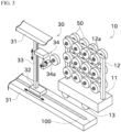
FIG. 3 is a perspective view of a package cart and a creel robot; -
FIG. 4 is a flowchart of a process in which a package of the package cart is transferred to a creel stand; -
FIG. 5 is a schematic plan view illustrating first and second states of the supply system; -
FIG. 6 is a schematic plan view illustrating third and fourth states of the supply system; -
FIG. 7 is a schematic plan view illustrating fifth and sixth states of the supply system, and -
FIG. 8 is a schematic plan view illustrating seventh and eighth states of the supply system. - Next, an embodiment of the present application will be described with reference to drawings. Components forming a
package supply system 1 will be described with reference toFIG. 1 to FIG. 3 . - The
package supply system 1supplies packages 50 from a spinning winder (not illustrated) to a draw false-twist texturing machine 60. The draw false-twist texturing machine 60 is a type of draw false-twist texturing machine and a type of yarn processor. Examples of the yarn processor include an air texturing machine. The draw false-twist texturing machine 60 draws and twists the semi-drawn yarn (partially oriented yarn) called POY, which is a type of yarn, to produce the draw textured yarn called DTY. POY is an abbreviation for Partially Oriented Yarn. DTY is an abbreviation for Draw Textured Yarn. The draw false-twist texturing machine 60 includes a plurality of processing positions for drawing and false-twisting. - Each
package 50 is POY with a predetermined length wound around a core tube. The POY produced by a spinning device of the spinning winder is wound around the core tube by a winding device of the spinning winder to form eachpackage 50. Thepackages 50 are transferred to and set on acreel stand 61 included in the draw false-twist texturing machine 60. The plurality ofpackages 50 can be set on thecreel stand 61 and arranged in a vertical direction and a horizontal direction. The yarn is unwound from eachpackage 50 set on the creel stand 61 toward a processing position. - In the
package supply system 1, thepackages 50 are automatically conveyed and transferred to thecreel stand 61. The term of "automatically conveyed" means that conveyance is performed using only a conveyance device without manual operations. However, at a time of occurrence of abnormality, operations by an operator may be required. Thepackage supply system 1 of the present embodiment may also be applied not only to automatic conveyance, but also to semi-automatic conveyance in which the conveyance is performed partially by the operator. Thepackage supply system 1 includes apackage cart 10, an AGV (Automatic Guided Vehicle) 20, acreel robot 30, and anintegrated controller 40. TheAGV 20 corresponds to the "conveyance device". - The
package cart 10 is used to collectively store thepackages 50 formed by the spinning winder. Thepackages 50 formed by the spinning winder are hooked onto thepackage cart 10. The operation in which thepackages 50 are hooked onto thepackage cart 10 is performed by a dedicated or general-purpose automatic machine, for example. As illustrated inFIG. 2 , thepackage cart 10 includes abase 11, apackage hooking stand 12, andwheels 13. - The
package hooking stand 12 and thewheels 13 are provided on thebase 11. TheAGV 20 uses abottom part 1 1a of the base 11 to cause thepackage cart 10 to be moved (details will be described later). - A plurality of
pegs 12a is provided in thepackage hooking stand 12. Each of thepegs 12a is an elongated member whose size is smaller than an inner diameter of the core tube. In the present embodiment, longitudinal directions of all thepegs 12a are parallel to each other. Hereinafter, one side in the longitudinal direction of eachpeg 12a (in other words, an axial direction of the core tube of each package 50) will be referred to as a first side, and the other side will be referred to as a second side. In thepackage hooking stand 12, a surface on the first side will be referred to as a first surface, and a surface on the second side will be referred to as a second surface. Therefore, the first surface is opposite to the second surface. Thepegs 12a are provided on both the first surface and the second surface. This allows thepackage cart 10 to hook thepackages 50 onto both the first surface and the second surface. Thepegs 12a are also arranged side by side in a height direction and the horizontal direction. - The
wheels 13 are provided in a lower part of thepackage hooking stand 12. Thewheels 13 are used when the operator pushes and moves thepackage cart 10. Thewheels 13 may be omitted. - The
AGV 20 is a vehicle that conveys thepackage cart 10 from the spinning winder toward thecreel robot 30. In detail, theAGV 20 collects thepackage cart 10 onto which thepackages 50 are hooked, and conveys thepackage cart 10 to afirst standby position 101 or asecond standby position 102 illustrated inFIG. 1 . Thefirst standby position 101 and thesecond standby position 102 are positions where thepackage cart 10 is on standby to transfer thepackages 50 to thecreel stand 61. A direction from thefirst standby position 101 to thesecond standby position 102 in a plan view is referred to as a first direction. As illustrated inFIGS. 1 and2 , theAGV 20 includes amain body part 21 and a slide table 22. - The
main body part 21 includes a driving source (such as a motor) for autonomous traveling, atravel part 21a driven by the driving source, and a controller. The controller corresponding to a PLC controls the driving source and the like, so that thetravel part 21a is driven in rotation to cause themain body part 21 to autonomously travel. Themain body part 21 also includes a mechanism and actuator for changing an orientation of thetravel part 21a. This allows themain body part 21 to travel in various orientations. - A space for placing a plurality of
package carts 10 is provided on an upper surface of themain body part 21. TheAGV 20 travels with thepackage carts 10 loaded thereon to convey thepackage carts 10. In the present embodiment, threepackage carts 10 can be transported, but the number ofpackage carts 10 may be two or four or more. - The slide table 22 is a device for loading the
package cart 10 onto themain body part 21 and unloading thepackage cart 10 from themain body part 21. To load thepackage cart 10 onto themain body part 21, firstly, the slide table is extended and inserted below thebottom part 11a, and then, the slide table is lifted and retracted. The slide table also has a function of holding thepackage cart 10 during conveyance of thepackage cart 10. With thepackage cart 10 being held, the controller causes thetravel part 21a to travel, so that thepackage cart 10 is moved. To unload thepackage cart 10 from themain body part 21, the slide table is extended to place thepackage cart 10 above thefirst standby position 101 or thesecond standby position 102, and then the slide table is lowered. - In such a manner, the
package cart 10 is moved from thefirst standby position 101 to thesecond standby position 102, so that thepackage cart 10 can be moved while keeping the orientation of thepackage cart 10. Therefore, a structure and a space for causing thepackage cart 10 to be reversed are not required. Keeping of the orientation of thepackage cart 10 means that the orientation of thepackage cart 10 is rarely or never reversed. - The
AGV 20 functions as a supply device by cooperation of thetravel part 21a, the slide table 22, and the controller. The supply device supplies the package cart 10 (particularly thepackage hooking stand 12, the same applies below) to thefirst standby position 101 or thesecond standby position 102, and collects thepackage cart 10 from thefirst standby position 101 or thesecond standby position 102. - The
AGV 20 further functions as a transport device by cooperation of thetravel part 21a, the slide table 22, and the controller. The transport device causes thepackage cart 10 located at thefirst standby position 101 to be moved to thesecond standby position 102. The transport device also includes a slide part and a movement part serving as functional parts. The slide part causes thepackage cart 10 to be moved in the first direction. The movement part causes thepackage cart 10 to be moved in a direction intersecting the first direction (in the present embodiment, a direction perpendicular to the first direction). - Instead of the slide table 22, a slide fork can be used. Instead of the slide table 22, a configuration in which the
package cart 10 is held and lifted may be provided. At least one of the above-mentioned supply device and transport device may be provided on a component other than theAGV 20. For example, a conveyor that connects thefirst standby position 101 and thesecond standby position 102 may be provided as the supply device or the transport device as long as an interference with other devices can be avoided. The supply device and the transport device may be realized by separate machines. TheAGV 20 is an example of the conveyance device. Instead of theAGV 20, a conveyance device that is not a vehicle (for example, a conveyor) may be used. - The
creel robot 30 collects thepackages 50 of thepackage cart 10 located at thefirst standby position 101 or thesecond standby position 102 and transfers the collectedpackages 50 to thecreel stand 61. Thecreel robot 30 moves along apredetermined movement route 100. As illustrated inFIG. 1 , themovement route 100 is set between thefirst standby position 101 and thesecond standby position 102 in a plan view. Specifically, one surface (specifically, second surface) of thepackage cart 10 located at thefirst standby position 101 faces themovement route 100. Furthermore, the other surface (more specifically, first surface) of thepackage cart 10 located at thesecond standby position 102 faces themovement route 100. Thecreel robot 30 can collect thepackages 50 hooked onto the surface facing themovement route 100. Furthermore, themovement route 100 is set between two creel stands 61 in a plan view. Thecreel robot 30 can transfer thepackages 50 to both of the creel stands 61. As illustrated inFIG. 3 , thecreel robot 30 includes arail 31, atravel part 32, asupport 33, and atransfer part 34. - The
rail 31 is provided along themovement route 100. Although therail 31 is formed on both a floor side and an overhead side in the present embodiment, therail 31 may be formed on only one of the both sides. Thetravel part 32 includes a driving source (such as a motor), wheels and the like. The driving source drives the wheels, so that thetravel part 32 moves along therail 31. A controller is provided in thetravel part 32. The controller corresponding to a PLC controls the driving source and the like, so that thetravel part 32 and thetransfer part 34 which will be described later are driven. - The
support 33 is provided in thetravel part 32. Thesupport 33 extends in the height direction. Thetransfer part 34 is provided in thesupport 33. Thetransfer part 34 is movable along thesupport 33 in the height direction. Thetransfer part 34 can be expanded and contracted, and includes aconveyance rod 34a capable of being inserted into the core tube of eachpackage 50. A part of thetransfer part 34 including theconveyance rod 34a is attached and rotatable along a rotation axis parallel to the height direction. The power of an actuator (not illustrated) rotates the part of thetransfer part 34 including theconveyance rod 34a, so that an orientation of theconveyance rod 34a can be changed. As a result, thetransfer part 34 can collect bothpackages 50 of twopackage carts 10 arranged on opposite sides of themovement route 100, and can transfer thepackages 50 to both of the two creel stands 61 arranged on the opposite sides of themovement route 100. - At a time of collection of the
packages 50, thecreel robot 30 causes the part of thetransfer part 34 including theconveyance rod 34a to rotate, so that theconveyance rod 34a is directed to a side where thepackages 50 to be collected are positioned. Next, by the travel of thetravel part 32, thecreel robot 30 aligns the position of the core tube of eachpackage 50 to be collected with the position of theconveyance rod 34a in the travel direction of thecreel robot 30. Subsequently, by the movement of thetransfer part 34 in the height direction, the position of the core tube of eachpackage 50 to be collected is aligned with the position of theconveyance rod 34a in the height direction. Then, theconveyance rod 34a is inserted into the core tube of eachpackage 50 to be collected and lifted up, which collects thepackages 50. As with transferring of thepackages 50, theconveyance rod 34a is directed toward the creel stand 61 as a destination, and then, the position of a peg of the creel stand 61 as the destination is aligned with the position of theconveyance rod 34a. After that, theconveyance rod 34a causes eachpackage 50 to be moved, and the core tube of eachpackage 50 passes through the peg of the creel stand 61 to transfer eachpackage 50. - In the present embodiment, the orientation of the
conveyance rod 34a is changed, which can collect and transfer thepackages 50 positioned on the opposite sides of theconveyance rod 34a in the travel direction. Alternatively, twoconveyance rods 34a with different orientations may be provided, which collects and transfers thepackages 50 positioned on the opposite sides of eachconveyance rod 34a in the travel direction. - The
integrated controller 40 is a computer including a CPU, a memory, a storage, and a communication module. Theintegrated controller 40 executes various controls related to thepackage supply system 1 by the CPU reading and executing programs stored in the storage. For example, theintegrated controller 40 transmits commands to theAGV 20 to collect and supply thepackage cart 10. For example, theintegrated controller 40 transmits commands to thecreel robot 30 to collect and transfer thepackages 50. - Next, a process in which the
packages 50 hooked onto thepackage cart 10 are supplied to the draw false-twist texturing machine 60 will be described with reference toFIG. 4 to FIG. 8 . Theintegrated controller 40 mainly executes the process illustrated inFIG. 4 , but the controller of theAGV 20 or thecreel robot 30 may execute at least a part of the process. - Firstly, the supply device of the
AGV 20 receives the commands from the integratedcontroller 40 and supplies thepackage cart 10 to the first standby position 101 (S101,State 1 inFIG. 5 ). As a result, the second surface of thepackage cart 10 located at thefirst standby position 101 faces themovement route 100. Next, upon receiving the commands from the integratedcontroller 40, thecreel robot 30 collects thepackages 50 on the second surface of thepackage cart 10 located at the first standby position 101 (S102,State 2 inFIG. 5 ). Thepackages 50 collected by thecreel robot 30 are transferred to thecreel stand 61. In the following, the description of the transfer of thepackages 50 to thecreel stand 61 will be omitted. - The
integrated controller 40 determines whether the collection of thepackages 50 on the second surface of thepackage cart 10 located at thefirst standby position 101 has been completed (S103). When theintegrated controller 40 determines that the collection of thepackages 50 has been completed, theintegrated controller 40 transmits the commands to theAGV 20. Upon receiving the commands from the integratedcontroller 40, the transport device of theAGV 20 moves thepackage cart 10 from thefirst standby position 101 to the second standby position 102 (S104,State 3 inFIG. 6 ). In detail, the movement part of the transport device of theAGV 20 causes thepackage cart 10 located at thefirst standby position 101 to be moved in a direction intersecting the first direction in a plan view (specifically, a direction perpendicular to the first direction). Next, the slide part of the transport device of theAGV 20 travels in the above-mentioned first direction while holding thepackage cart 10, and causes thepackage cart 10 to be moved in the first direction. Subsequently, the movement part of the transport device of theAGV 20 causes thepackage cart 10 to be moved in the direction intersecting the first direction in the plan view (specifically, the direction perpendicular to the first direction), so that thepackage cart 10 is located at thesecond standby position 102. As a result, the first surface of thepackage cart 10 located at thesecond standby position 102 faces themovement route 100. Then, upon receiving the commands from the integratedcontroller 40, thecreel robot 30 collects thepackages 50 on the first surface of thepackage cart 10 located at the second standby position 102 (S105). - When the
package cart 10 is moved from thefirst standby position 101 to thesecond standby position 102, thefirst standby position 101 becomes vacant. Thus, theintegrated controller 40 transmits commands to theAGV 20. Upon receiving the commands from the integratedcontroller 40, theAGV 20 supplies anew package cart 10 to the first standby position 101 (S106,State 4 inFIG. 6 ). Accordingly, the second surface of thenew package cart 10 located at thefirst standby position 101 faces themovement route 100. - Here, in the middle of the operation in which the
package cart 10 is supplied to thefirst standby position 101, thecreel robot 30 collects thepackages 50 from thepackage cart 10 located at thesecond standby position 102. This can improve work efficiency. - In such a state, the
creel robot 30 can collect thepackages 50 from thepackage cart 10 located at both thefirst standby position 101 and thesecond standby position 102. In the present embodiment, thepackages 50 located at thesecond standby position 102 are preferentially collected. Theintegrated controller 40 determines whether collection of thepackages 50 on the first surface of thepackage cart 10 located at thesecond standby position 102 has been completed (S107). When theintegrated controller 40 determines that collection of thepackages 50 has been completed, theintegrated controller 40 transmits the commands to theAGV 20. Upon receiving the commands from the integratedcontroller 40, the supply device of theAGV 20 collects thepackage cart 10 located at the second standby position 102 (S108,State 5 inFIG. 7 ). As above, thepackages 50 on the first surface and the second surface of thepackage cart 10 can be collected without reversing thepackage cart 10. - Here, in the middle of the operation in which the
package cart 10 located at thesecond standby position 102 is collected, thecreel robot 30 collects thepackages 50 from thepackage cart 10 located at thefirst standby position 101. This can improve work efficiency. In summary, in the present embodiment, there are two standby positions, and thecreel robot 30 can collect thepackages 50 from thepackage carts 10 at both of the two standby positions. Therefore, even when thecreel robot 30 is in the middle of supplying or collecting thepackages 50 of thepackage cart 10 located at one standby position, thecreel robot 30 can collect the packages from thepackage cart 10 located at the other standby position. - The
package cart 10 that is newly supplied in Step S106 is treated in the same way as thepackage cart 10 that is first supplied. In the following, the repeated descriptions will be explained briefly. Thecreel robot 30 collects thepackages 50 on the second surface of thepackage cart 10 located at the first standby position 101 (S109). When theintegrated controller 40 determines that thepackages 50 have been collected (S110), the transport device of theAGV 20 causes thepackage cart 10 to be moved from thefirst standby position 101 to the second standby position 102 (S104,State 6 inFIG. 7 ). Next, thecreel robot 30 collects thepackages 50 on the first surface of thepackage cart 10 located at the second standby position 102 (S105). The supply device of theAGV 20 supplies anew package cart 10 to the first standby position 101 (S106,State 7 inFIG. 8 ). After that, thepackage cart 10 located at thesecond standby position 102 is collected by theAGV 20 after thepackages 50 are collected (S108,State 8 inFIG. 8 ). - The
AGV 20 returns thepackage cart 10 in which thepackages 50 have been collected, to the vicinity of the spinning winder at an appropriate time. TheAGV 20 collects thepackage cart 10 onto which thepackages 50 have been hung, alternatively. - The above-mentioned processes are repeated, which can collect the
packages 50 hung on the first and second surfaces of thepackage cart 10, without thepackage cart 10 being reversed. Therefore, compared to a configuration in which thepackage cart 10 is reversed, a structure and space required for reversing thepackage cart 10 are not required. Thus, the packages can be automatically collected with a simple structure and low cost. - As described above, the
package supply system 1 of the present embodiment includes thepackage hooking stand 12, thecreel robot 30, the supply device, and the transport device. Thepackage hooking stand 12 has the first surface and the second surface, and the plurality ofpegs 12a onto which thepackages 50 are hung is provided on each of the first surface and the second surface. Thecreel robot 30 moves along themovement route 100 between thefirst standby position 101 and thesecond standby position 102 of thepackage hooking stand 12, and collects thepackages 50 hung on thepegs 12a on the second surface of thepackage hooking stand 12 located at thefirst standby position 101 or thepackages 50 hung on thepegs 12a on the first surface of thepackage hooking stand 12 located at thesecond standby position 102. Thecreel robot 30 then transfers thepackages 50 to the creel stand 61 of the yarn processor. The supply device supplies thepackage hooking stand 12 to the first standby position. After thecreel robot 30 transfers thepackages 50 hung on thepeg 12a on one surface (second surface) of thepackage hooking stand 12 located at thefirst standby position 101 to thecreel stand 61, the transport device causes thepackage hooking stand 12 to be moved from thefirst standby position 101 to thesecond standby position 102 while keeping the orientation of thepackage hooking stand 12. This allows the other surface (first surface) of thepackage hooking stand 12 to face themovement route 100 of thecreel robot 30. - Accordingly, the
packages 50 hung on opposite sides of thepackage hooking stand 12 can be collected while keeping the orientation of thepackage hooking stand 12. Thus, a system for collecting the packages can be achieved with a simple structure. Since the structure is simple, the equipment cost is likely to be low and the layout in the factory can be flexibly changed. In addition, since the standby positions are provided on opposite sides of thecreel robot 30, thepackages 50 can be supplied from onepackage hooking stand 12 to thecreel robot 30 even during the supply or transport of the otherpackage hooking stand 12. - The
package supply system 1 of the present embodiment includes theAGV 20 that transports thepackage hooking stand 12 to thecreel robot 30. - This can automate the operation in which the
package hooking stand 12 is transported to thecreel robot 30. - In the
package supply system 1 of the present embodiment, the supply device is provided in theAGV 20. - Accordingly, the
AGV 20 is used to perform both the supply and transfer of thepackage hooking stand 12. - In the
package supply system 1 of the present embodiment, the transport device is provided in theAGV 20. - Accordingly, the
AGV 20 is used to perform both the supply and transfer of thepackage hooking stand 12. - In the
package supply system 1 of the present embodiment, when thepackage hooking stand 12 is not located at thefirst standby position 101, the supply device supplies thepackage hooking stand 12 to thefirst standby position 101. The transport device causes thepackage hooking stand 12 located at thefirst standby position 101 to be moved to thesecond standby position 102. The supply device supplies thepackage hooking stand 12 to thefirst standby position 101. The supply device collects thepackage hooking stand 12 located at thesecond standby position 102. - This can smoothly perform the supply of the
package hooking stand 12, the collection of thepackages 50, and the collection of thepackage hooking stand 12. - In the
package supply system 1 of the present embodiment, a direction from thefirst standby position 101 to thesecond standby position 102 is referred to as the first direction. The transport device includes the slide part that allows thepackage hooking stand 12 to be moved in the first direction. - This allows the
package hooking stand 12 to be moved in the first direction (in a direction approaching thesecond standby position 102 from the first standby position 101) while keeping the orientation of thepackage hooking stand 12. - In the
package supply system 1 of the present embodiment, the transport device includes the movement part that causes thepackage hooking stand 12 to be moved in the direction intersecting the first direction in the plan view. After the movement part causes thepackage hooking stand 12 located at thefirst standby position 101 to be moved in the direction intersecting the first direction in the plan view, the slide part causes thepackage hooking stand 12 to be moved in the first direction. After that, the movement part causes thepackage hooking stand 12 to be moved in the direction intersecting the first direction in the plan view and to be located at thesecond standby position 102. - This allows the
package hooking stand 12 located at thefirst standby position 101 to be moved to thesecond standby position 102 while keeping the orientation of thepackage hooking stand 12. - In the
package supply system 1 of the present embodiment, thecreel stand 61 is provided on each of the first and second sides of themovement route 100 of thecreel robot 30. Thecreel robot 30 can transfer the collectedpackages 50 to each creel stand 61 on the first and second sides. - This allows the
creel robot 30 to collect thepackages 50 on the opposite sides of themovement route 100. Thus, by utilizing the same function, thecreel robot 30 can transfer thepackages 50 to the creel stand 61 on the opposite sides of themovement route 100. - Although a preferred embodiment of the present invention has been described as above, the above-described configuration may be modified as follows, for example.
- The flowchart illustrated in the present embodiment is an example. A part of the process may be omitted, and contents of the part of the process may be modified. A new process may be added. For example, the order of Step S105 and Step S106 may be exchanged, or they may be performed simultaneously in parallel. Similarly, the order of Step S108 and
Step S 109 may be exchanged, or they may be performed simultaneously in parallel. Thecreel robot 30 collects or transfers thepackages 50 while theAGV 20 performs supply, movement, or collection of thepackage cart 10, which improves work efficiency.
Claims (10)
- A package supply system (1) comprising:a package hooking stand (12) having a first surface and a second surface,
the first surface and the second surface on which a plurality of pegs (12a) for hooking packages (50) is provided;a creel robot (30) configured to:move along a movement route between a first standby position and a second standby position of the package hooking stand (12);collect the packages (50) hung on the pegs (12a) on the second surface of the package hooking stand (12) located at the first standby position or the packages (50) hung on the pegs (12a) on the first surface of the package hooking stand (12) located at the second standby position; andtransfer the packages (50) to a creel stand (61) of a yarn processor;a supply device configured to supply the package hooking stand (12) to the first standby position; anda transport device configured to cause one of the first surface and the second surface of the package hooking stand (12) to face the movement route of the creel robot (30) by moving the package hooking stand (12) from the first standby position to the second standby position while keeping an orientation of the package hooking stand (12), after the creel robot (30) transfers the packages (50) hung on the pegs (12a) on the other of the first surface and the second surface of the package hooking stand (12) located at the first standby position to the creel stand (61). - The package supply system (1) according to claim 1, wherein
the package supply system (1) comprises a conveyance device (20) configured to convey the package hooking stand (12) to the creel robot (30). - The package supply system (1) according to claim 2, wherein
the supply device is provided in the conveyance device (20). - The package supply system (1) according to claim 2 or 3, wherein
the transport device is provided in the conveyance device (20). - The package supply system (1) according to any one of claims 2 to 4, wherein
the conveyance device (20) is a vehicle. - The package supply system (1) according to any one of claims 1 to 5, whereinthe supply device is configured to supply the package hooking stand (12) to the first standby position when the package hooking stand (12) is not located at the first standby position,the transport device is configured to cause the package hooking stand (12) located at the first standby position to be moved to the second standby position,the supply device is configured to supply the package hooking stand (12) to the first standby position, andthe supply device is configured to collect the package hooking stand (12) located at the second standby position.
- The package supply system (1) according to any one of claims 1 to 6, whereinin a plan view, a direction from the first standby position toward the second standby position is referred to as a first direction, andthe transport device includes a slide part that causes the package hooking stand (12) to be moved in the first direction.
- The package supply system (1) according to claim 7, whereinthe transport device includes a movement part that causes the package hooking stand (12) to be moved in a direction intersecting the first direction in a plan view,after the movement part causes the package hooking stand (12) located at the first standby position to be moved in the direction intersecting the first direction in the plan view,the slide part causes the package hooking stand (12) to be moved in the first direction, andafter that, the movement part causes the package hooking stand (12) to be moved in the direction intersecting the first direction in the plan view to position the package hooking stand (12) at the second standby position.
- The package supply system (1) according to any one of claims 1 to 8, wherein
the transport device is configured to cause the first surface of the package hooking stand (12) to face the movement route of the creel robot (30) after the creel robot (30) transfers the packages (50) hung on the pegs (12a) on the second surface of the package hooking stand (12) to the creel stand (61). - The package supply system (1) according to any one of claims 1 to 9, whereincreel stands (61) are respectively provided on opposite sides that are a first side and a second side of the movement route of the creel robot (30), andthe creel robot (30) is capable of transferring the packages (50) that have been collected, to the respective creel stands (61) on the first side and the second side.
Applications Claiming Priority (1)
| Application Number | Priority Date | Filing Date | Title |
|---|---|---|---|
| JP2023199275A JP2025085415A (en) | 2023-11-24 | 2023-11-24 | Package Supply System |
Publications (1)
| Publication Number | Publication Date |
|---|---|
| EP4559852A1 true EP4559852A1 (en) | 2025-05-28 |
Family
ID=93014070
Family Applications (1)
| Application Number | Title | Priority Date | Filing Date |
|---|---|---|---|
| EP24204579.7A Pending EP4559852A1 (en) | 2023-11-24 | 2024-10-04 | Package supply system |
Country Status (4)
| Country | Link |
|---|---|
| EP (1) | EP4559852A1 (en) |
| JP (1) | JP2025085415A (en) |
| CN (1) | CN120039720A (en) |
| TW (1) | TW202521458A (en) |
Citations (8)
| Publication number | Priority date | Publication date | Assignee | Title |
|---|---|---|---|---|
| JPS6071469A (en) * | 1983-09-29 | 1985-04-23 | Teijin Eng Kk | Automatic feeder for cop |
| DE4213049A1 (en) * | 1991-04-19 | 1992-10-22 | Murata Machinery Ltd | Bobbin changer for cross-wound conical bobbin - has conveyor with pins and robot to move bobbins and sleeves between the creel and conveyor |
| JPH0532377A (en) * | 1991-07-26 | 1993-02-09 | Murata Mach Ltd | Yarn supply exchange system of draw false twisting machine |
| JPH0532377B2 (en) | 1988-07-13 | 1993-05-14 | Rhone Poulenc Chimie | |
| US5218748A (en) * | 1991-03-06 | 1993-06-15 | Tsudakoma Kogyo Kabushiki Kaisha | Method for exchanging packages on a textile machine |
| JPH05302229A (en) * | 1992-04-24 | 1993-11-16 | Tsudakoma Corp | Feeder exchange system having v-shaped creel |
| JPH07157199A (en) * | 1993-10-22 | 1995-06-20 | Ooishi Sangyo:Kk | Creel threading system and method |
| CN113526229A (en) * | 2020-04-17 | 2021-10-22 | 阳程科技股份有限公司 | Yarn bobbin feeding device and method thereof |
-
2023
- 2023-11-24 JP JP2023199275A patent/JP2025085415A/en active Pending
-
2024
- 2024-09-29 CN CN202411368062.8A patent/CN120039720A/en active Pending
- 2024-10-04 EP EP24204579.7A patent/EP4559852A1/en active Pending
- 2024-10-16 TW TW113139250A patent/TW202521458A/en unknown
Patent Citations (8)
| Publication number | Priority date | Publication date | Assignee | Title |
|---|---|---|---|---|
| JPS6071469A (en) * | 1983-09-29 | 1985-04-23 | Teijin Eng Kk | Automatic feeder for cop |
| JPH0532377B2 (en) | 1988-07-13 | 1993-05-14 | Rhone Poulenc Chimie | |
| US5218748A (en) * | 1991-03-06 | 1993-06-15 | Tsudakoma Kogyo Kabushiki Kaisha | Method for exchanging packages on a textile machine |
| DE4213049A1 (en) * | 1991-04-19 | 1992-10-22 | Murata Machinery Ltd | Bobbin changer for cross-wound conical bobbin - has conveyor with pins and robot to move bobbins and sleeves between the creel and conveyor |
| JPH0532377A (en) * | 1991-07-26 | 1993-02-09 | Murata Mach Ltd | Yarn supply exchange system of draw false twisting machine |
| JPH05302229A (en) * | 1992-04-24 | 1993-11-16 | Tsudakoma Corp | Feeder exchange system having v-shaped creel |
| JPH07157199A (en) * | 1993-10-22 | 1995-06-20 | Ooishi Sangyo:Kk | Creel threading system and method |
| CN113526229A (en) * | 2020-04-17 | 2021-10-22 | 阳程科技股份有限公司 | Yarn bobbin feeding device and method thereof |
Also Published As
| Publication number | Publication date |
|---|---|
| CN120039720A (en) | 2025-05-27 |
| JP2025085415A (en) | 2025-06-05 |
| TW202521458A (en) | 2025-06-01 |
Similar Documents
| Publication | Publication Date | Title |
|---|---|---|
| KR102279602B1 (en) | Article transport facility | |
| KR102636990B1 (en) | Transport vehicle and transport equipment | |
| US8374719B2 (en) | Article processing facility and its control method | |
| CN102869587B (en) | Item conveying equipment | |
| CN111071862B (en) | Automatic loading and unloading system for winding reels, its loading and unloading methods, and winding production line | |
| US20240051745A1 (en) | Article Storage Facility | |
| JP2018188236A (en) | Picking system | |
| JP2023064851A (en) | Cargo loading and unloading system | |
| CN111874750A (en) | Intelligent wire replacing system | |
| JP2025085415A (en) | Package Supply System | |
| JPH02242930A (en) | Pallet loading apparatus | |
| JP2000124284A (en) | Transfer device | |
| KR20250111424A (en) | Flexible picking equipment and loading/unloading method of automatic warehouse system using the same | |
| CN212292351U (en) | Intelligent wire replacing system | |
| JP4626812B2 (en) | Goods transport equipment | |
| JPS63268010A (en) | Carrying device | |
| CN117262902B (en) | Cylindrical conveying system and cylindrical conveying method | |
| JP2022064679A (en) | Picking system | |
| EP2045380A2 (en) | Method and system for automatically creeling and uncreeling warping creels | |
| CN211971664U (en) | Automatic guide transport vehicle | |
| JPH11293530A (en) | Cheese transfer device and cheese transporter | |
| JPH05195347A (en) | Can carrying truck for performing automatic can exchange | |
| JPH0540261U (en) | Creel carrier | |
| JPS63267390A (en) | combined production line | |
| KR20250013175A (en) | Return facility |
Legal Events
| Date | Code | Title | Description |
|---|---|---|---|
| PUAI | Public reference made under article 153(3) epc to a published international application that has entered the european phase |
Free format text: ORIGINAL CODE: 0009012 |
|
| STAA | Information on the status of an ep patent application or granted ep patent |
Free format text: STATUS: THE APPLICATION HAS BEEN PUBLISHED |
|
| AK | Designated contracting states |
Kind code of ref document: A1 Designated state(s): AL AT BE BG CH CY CZ DE DK EE ES FI FR GB GR HR HU IE IS IT LI LT LU LV MC ME MK MT NL NO PL PT RO RS SE SI SK SM TR |
|
| STAA | Information on the status of an ep patent application or granted ep patent |
Free format text: STATUS: REQUEST FOR EXAMINATION WAS MADE |
|
| 17P | Request for examination filed |
Effective date: 20250709 |
|
| STAA | Information on the status of an ep patent application or granted ep patent |
Free format text: STATUS: EXAMINATION IS IN PROGRESS |
|
| 17Q | First examination report despatched |
Effective date: 20260417 |