EP4559810A1 - Nest for unmanned aerial vehicle, vehicle and control method - Google Patents
Nest for unmanned aerial vehicle, vehicle and control method Download PDFInfo
- Publication number
- EP4559810A1 EP4559810A1 EP23841840.4A EP23841840A EP4559810A1 EP 4559810 A1 EP4559810 A1 EP 4559810A1 EP 23841840 A EP23841840 A EP 23841840A EP 4559810 A1 EP4559810 A1 EP 4559810A1
- Authority
- EP
- European Patent Office
- Prior art keywords
- unmanned aerial
- aerial vehicle
- battery
- hangar
- charging
- Prior art date
- Legal status (The legal status is an assumption and is not a legal conclusion. Google has not performed a legal analysis and makes no representation as to the accuracy of the status listed.)
- Pending
Links
Images







Classifications
-
- B—PERFORMING OPERATIONS; TRANSPORTING
- B60—VEHICLES IN GENERAL
- B60L—PROPULSION OF ELECTRICALLY-PROPELLED VEHICLES; SUPPLYING ELECTRIC POWER FOR AUXILIARY EQUIPMENT OF ELECTRICALLY-PROPELLED VEHICLES; ELECTRODYNAMIC BRAKE SYSTEMS FOR VEHICLES IN GENERAL; MAGNETIC SUSPENSION OR LEVITATION FOR VEHICLES; MONITORING OPERATING VARIABLES OF ELECTRICALLY-PROPELLED VEHICLES; ELECTRIC SAFETY DEVICES FOR ELECTRICALLY-PROPELLED VEHICLES
- B60L53/00—Methods of charging batteries, specially adapted for electric vehicles; Charging stations or on-board charging equipment therefor; Exchange of energy storage elements in electric vehicles
-
- B—PERFORMING OPERATIONS; TRANSPORTING
- B60—VEHICLES IN GENERAL
- B60S—SERVICING, CLEANING, REPAIRING, SUPPORTING, LIFTING, OR MANOEUVRING OF VEHICLES, NOT OTHERWISE PROVIDED FOR
- B60S5/00—Servicing, maintaining, repairing, or refitting of vehicles
- B60S5/06—Supplying batteries to, or removing batteries from, vehicles
-
- B—PERFORMING OPERATIONS; TRANSPORTING
- B60—VEHICLES IN GENERAL
- B60L—PROPULSION OF ELECTRICALLY-PROPELLED VEHICLES; SUPPLYING ELECTRIC POWER FOR AUXILIARY EQUIPMENT OF ELECTRICALLY-PROPELLED VEHICLES; ELECTRODYNAMIC BRAKE SYSTEMS FOR VEHICLES IN GENERAL; MAGNETIC SUSPENSION OR LEVITATION FOR VEHICLES; MONITORING OPERATING VARIABLES OF ELECTRICALLY-PROPELLED VEHICLES; ELECTRIC SAFETY DEVICES FOR ELECTRICALLY-PROPELLED VEHICLES
- B60L53/00—Methods of charging batteries, specially adapted for electric vehicles; Charging stations or on-board charging equipment therefor; Exchange of energy storage elements in electric vehicles
- B60L53/30—Constructional details of charging stations
-
- B—PERFORMING OPERATIONS; TRANSPORTING
- B60—VEHICLES IN GENERAL
- B60L—PROPULSION OF ELECTRICALLY-PROPELLED VEHICLES; SUPPLYING ELECTRIC POWER FOR AUXILIARY EQUIPMENT OF ELECTRICALLY-PROPELLED VEHICLES; ELECTRODYNAMIC BRAKE SYSTEMS FOR VEHICLES IN GENERAL; MAGNETIC SUSPENSION OR LEVITATION FOR VEHICLES; MONITORING OPERATING VARIABLES OF ELECTRICALLY-PROPELLED VEHICLES; ELECTRIC SAFETY DEVICES FOR ELECTRICALLY-PROPELLED VEHICLES
- B60L53/00—Methods of charging batteries, specially adapted for electric vehicles; Charging stations or on-board charging equipment therefor; Exchange of energy storage elements in electric vehicles
- B60L53/30—Constructional details of charging stations
- B60L53/32—Constructional details of charging stations by charging in short intervals along the itinerary, e.g. during short stops
-
- B—PERFORMING OPERATIONS; TRANSPORTING
- B60—VEHICLES IN GENERAL
- B60L—PROPULSION OF ELECTRICALLY-PROPELLED VEHICLES; SUPPLYING ELECTRIC POWER FOR AUXILIARY EQUIPMENT OF ELECTRICALLY-PROPELLED VEHICLES; ELECTRODYNAMIC BRAKE SYSTEMS FOR VEHICLES IN GENERAL; MAGNETIC SUSPENSION OR LEVITATION FOR VEHICLES; MONITORING OPERATING VARIABLES OF ELECTRICALLY-PROPELLED VEHICLES; ELECTRIC SAFETY DEVICES FOR ELECTRICALLY-PROPELLED VEHICLES
- B60L53/00—Methods of charging batteries, specially adapted for electric vehicles; Charging stations or on-board charging equipment therefor; Exchange of energy storage elements in electric vehicles
- B60L53/50—Charging stations characterised by energy-storage or power-generation means
- B60L53/57—Charging stations without connection to power networks
-
- B—PERFORMING OPERATIONS; TRANSPORTING
- B60—VEHICLES IN GENERAL
- B60L—PROPULSION OF ELECTRICALLY-PROPELLED VEHICLES; SUPPLYING ELECTRIC POWER FOR AUXILIARY EQUIPMENT OF ELECTRICALLY-PROPELLED VEHICLES; ELECTRODYNAMIC BRAKE SYSTEMS FOR VEHICLES IN GENERAL; MAGNETIC SUSPENSION OR LEVITATION FOR VEHICLES; MONITORING OPERATING VARIABLES OF ELECTRICALLY-PROPELLED VEHICLES; ELECTRIC SAFETY DEVICES FOR ELECTRICALLY-PROPELLED VEHICLES
- B60L53/00—Methods of charging batteries, specially adapted for electric vehicles; Charging stations or on-board charging equipment therefor; Exchange of energy storage elements in electric vehicles
- B60L53/80—Exchanging energy storage elements, e.g. removable batteries
-
- B—PERFORMING OPERATIONS; TRANSPORTING
- B60—VEHICLES IN GENERAL
- B60P—VEHICLES ADAPTED FOR LOAD TRANSPORTATION OR TO TRANSPORT, TO CARRY, OR TO COMPRISE SPECIAL LOADS OR OBJECTS
- B60P3/00—Vehicles adapted to transport, to carry or to comprise special loads or objects
- B60P3/06—Vehicles adapted to transport, to carry or to comprise special loads or objects for carrying vehicles
- B60P3/11—Vehicles adapted to transport, to carry or to comprise special loads or objects for carrying vehicles for carrying aircraft
-
- B—PERFORMING OPERATIONS; TRANSPORTING
- B64—AIRCRAFT; AVIATION; COSMONAUTICS
- B64F—GROUND OR AIRCRAFT-CARRIER-DECK INSTALLATIONS SPECIALLY ADAPTED FOR USE IN CONNECTION WITH AIRCRAFT; DESIGNING, MANUFACTURING, ASSEMBLING, CLEANING, MAINTAINING OR REPAIRING AIRCRAFT, NOT OTHERWISE PROVIDED FOR; HANDLING, TRANSPORTING, TESTING OR INSPECTING AIRCRAFT COMPONENTS, NOT OTHERWISE PROVIDED FOR
- B64F1/00—Ground or aircraft-carrier-deck installations
-
- B—PERFORMING OPERATIONS; TRANSPORTING
- B64—AIRCRAFT; AVIATION; COSMONAUTICS
- B64F—GROUND OR AIRCRAFT-CARRIER-DECK INSTALLATIONS SPECIALLY ADAPTED FOR USE IN CONNECTION WITH AIRCRAFT; DESIGNING, MANUFACTURING, ASSEMBLING, CLEANING, MAINTAINING OR REPAIRING AIRCRAFT, NOT OTHERWISE PROVIDED FOR; HANDLING, TRANSPORTING, TESTING OR INSPECTING AIRCRAFT COMPONENTS, NOT OTHERWISE PROVIDED FOR
- B64F1/00—Ground or aircraft-carrier-deck installations
- B64F1/007—Helicopter portable landing pads
-
- B—PERFORMING OPERATIONS; TRANSPORTING
- B64—AIRCRAFT; AVIATION; COSMONAUTICS
- B64U—UNMANNED AERIAL VEHICLES [UAV]; EQUIPMENT THEREFOR
- B64U50/00—Propulsion; Power supply
- B64U50/30—Supply or distribution of electrical power
- B64U50/39—Battery swapping
-
- B—PERFORMING OPERATIONS; TRANSPORTING
- B64—AIRCRAFT; AVIATION; COSMONAUTICS
- B64U—UNMANNED AERIAL VEHICLES [UAV]; EQUIPMENT THEREFOR
- B64U80/00—Transport or storage specially adapted for UAVs
- B64U80/10—Transport or storage specially adapted for UAVs with means for moving the UAV to a supply or launch location, e.g. robotic arms or carousels
-
- B—PERFORMING OPERATIONS; TRANSPORTING
- B64—AIRCRAFT; AVIATION; COSMONAUTICS
- B64U—UNMANNED AERIAL VEHICLES [UAV]; EQUIPMENT THEREFOR
- B64U80/00—Transport or storage specially adapted for UAVs
- B64U80/20—Transport or storage specially adapted for UAVs with arrangements for servicing the UAV
- B64U80/25—Transport or storage specially adapted for UAVs with arrangements for servicing the UAV for recharging batteries; for refuelling
-
- B—PERFORMING OPERATIONS; TRANSPORTING
- B64—AIRCRAFT; AVIATION; COSMONAUTICS
- B64U—UNMANNED AERIAL VEHICLES [UAV]; EQUIPMENT THEREFOR
- B64U80/00—Transport or storage specially adapted for UAVs
- B64U80/70—Transport or storage specially adapted for UAVs in containers
-
- B—PERFORMING OPERATIONS; TRANSPORTING
- B64—AIRCRAFT; AVIATION; COSMONAUTICS
- B64U—UNMANNED AERIAL VEHICLES [UAV]; EQUIPMENT THEREFOR
- B64U80/00—Transport or storage specially adapted for UAVs
- B64U80/80—Transport or storage specially adapted for UAVs by vehicles
- B64U80/86—Land vehicles
-
- E—FIXED CONSTRUCTIONS
- E04—BUILDING
- E04H—BUILDINGS OR LIKE STRUCTURES FOR PARTICULAR PURPOSES; SWIMMING OR SPLASH BATHS OR POOLS; MASTS; FENCING; TENTS OR CANOPIES, IN GENERAL
- E04H6/00—Buildings for parking cars, rolling-stock, aircraft, vessels or like vehicles, e.g. garages
- E04H6/44—Buildings for parking cars, rolling-stock, aircraft, vessels or like vehicles, e.g. garages for storing aircraft
-
- B—PERFORMING OPERATIONS; TRANSPORTING
- B60—VEHICLES IN GENERAL
- B60L—PROPULSION OF ELECTRICALLY-PROPELLED VEHICLES; SUPPLYING ELECTRIC POWER FOR AUXILIARY EQUIPMENT OF ELECTRICALLY-PROPELLED VEHICLES; ELECTRODYNAMIC BRAKE SYSTEMS FOR VEHICLES IN GENERAL; MAGNETIC SUSPENSION OR LEVITATION FOR VEHICLES; MONITORING OPERATING VARIABLES OF ELECTRICALLY-PROPELLED VEHICLES; ELECTRIC SAFETY DEVICES FOR ELECTRICALLY-PROPELLED VEHICLES
- B60L2200/00—Type of vehicles
- B60L2200/10—Air crafts
-
- B—PERFORMING OPERATIONS; TRANSPORTING
- B64—AIRCRAFT; AVIATION; COSMONAUTICS
- B64U—UNMANNED AERIAL VEHICLES [UAV]; EQUIPMENT THEREFOR
- B64U10/00—Type of UAV
- B64U10/10—Rotorcrafts
- B64U10/13—Flying platforms
- B64U10/14—Flying platforms with four distinct rotor axes, e.g. quadcopters
-
- Y—GENERAL TAGGING OF NEW TECHNOLOGICAL DEVELOPMENTS; GENERAL TAGGING OF CROSS-SECTIONAL TECHNOLOGIES SPANNING OVER SEVERAL SECTIONS OF THE IPC; TECHNICAL SUBJECTS COVERED BY FORMER USPC CROSS-REFERENCE ART COLLECTIONS [XRACs] AND DIGESTS
- Y02—TECHNOLOGIES OR APPLICATIONS FOR MITIGATION OR ADAPTATION AGAINST CLIMATE CHANGE
- Y02T—CLIMATE CHANGE MITIGATION TECHNOLOGIES RELATED TO TRANSPORTATION
- Y02T10/00—Road transport of goods or passengers
- Y02T10/60—Other road transportation technologies with climate change mitigation effect
- Y02T10/70—Energy storage systems for electromobility, e.g. batteries
-
- Y—GENERAL TAGGING OF NEW TECHNOLOGICAL DEVELOPMENTS; GENERAL TAGGING OF CROSS-SECTIONAL TECHNOLOGIES SPANNING OVER SEVERAL SECTIONS OF THE IPC; TECHNICAL SUBJECTS COVERED BY FORMER USPC CROSS-REFERENCE ART COLLECTIONS [XRACs] AND DIGESTS
- Y02—TECHNOLOGIES OR APPLICATIONS FOR MITIGATION OR ADAPTATION AGAINST CLIMATE CHANGE
- Y02T—CLIMATE CHANGE MITIGATION TECHNOLOGIES RELATED TO TRANSPORTATION
- Y02T10/00—Road transport of goods or passengers
- Y02T10/60—Other road transportation technologies with climate change mitigation effect
- Y02T10/7072—Electromobility specific charging systems or methods for batteries, ultracapacitors, supercapacitors or double-layer capacitors
Definitions
- the present disclosure belongs to the field of unmanned aerial vehicle devices, and in particular, to a hangar for an unmanned aerial vehicle, a vehicle, and a control method.
- a hangar for an unmanned aerial vehicle in the related art can be transported to a designated location by a vehicle, and then releases the unmanned aerial vehicle to perform related work.
- a battery life of the unmanned aerial vehicle is insufficient, the unmanned aerial vehicle is recovered and the battery lifetime is supplemented by manual battery replacement or charging.
- the unmanned aerial vehicle cannot be charged manually without stopping the vehicle.
- driving time of the vehicle may be long or short, it is difficult to ensure that the battery lifetime of the unmanned aerial vehicle can cover the driving time of the vehicle as much as possible.
- the present disclosure provides a hangar for an unmanned aerial vehicle, which can extend battery lifetime of the unmanned aerial vehicle by replacing batteries to adapt to a long-time driving scenario of a vehicle, and can also extend the battery lifetime of the unmanned aerial vehicle by charging to adapt to a scenario in which the vehicle finishes short-time driving, or the vehicle is parked, or the unmanned aerial vehicle does not need to follow the vehicle, thereby ensuring that the battery lifetime of the unmanned aerial vehicle can cover driving time of the vehicle as much as possible, to meet a requirement of following the vehicle.
- a hangar for an unmanned aerial vehicle suitable for being arranged on a vehicle, including:
- the first battery with insufficient power can be detached via the battery pick-and-place apparatus and the second battery with sufficient power can be mounted into the unmanned aerial vehicle in a process in which the unmanned aerial vehicle briefly returns to the hangar when the vehicle drives for a long time and the unmanned aerial vehicle has a requirement to continuously follow the vehicle, thereby quickly extending the battery life time of the unmanned aerial vehicle, so that the unmanned aerial vehicle continues to follow the vehicle.
- the unmanned aerial vehicle After the vehicle finishes short-time driving, or when the vehicle is parked, or when the unmanned aerial vehicle does not need to follow the vehicle, the unmanned aerial vehicle can be returned to the hangar for standby, and the unmanned aerial vehicle battery can be charged by the charging apparatus, thereby stably and sustainably meeting a battery life requirement of the unmanned aerial vehicle for following the vehicle next time.
- hangar for an unmanned aerial vehicle provided in the present disclosure may further have the following additional technical features.
- the battery pick-and-place apparatus includes a clamping mechanism.
- the clamping mechanism includes a first driving assembly and two clamping members.
- the first driving assembly is connected to at least one clamping member to drive the at least one clamping member to switch between a clamping state and a releasing state, when the clamping members are in the clamping state, the two clamping members are suitable for clamping the unmanned aerial vehicle battery, and when the clamping members are in the releasing state, the two clamping members are suitable for detaching from the unmanned aerial vehicle battery.
- the battery pick-and-place apparatus includes a lifting mechanism, and the lifting mechanism is suitable for cooperating with a bottom surface of the unmanned aerial vehicle battery to support the unmanned aerial vehicle battery.
- the hangar further includes a movable rack.
- the movable rack is movably arranged in the hangar body along a first direction
- the battery pick-and-place apparatus is movably arranged on the movable rack along a second direction.
- the first direction is not parallel to the second direction, and both the first direction and the second direction have the component in the horizontal plane direction.
- the hangar further includes a power-on/off apparatus.
- the power-on/off apparatus is arranged in the hangar body.
- the power-on/off apparatus is switchable between a trigger state and an avoidance state.
- the power-on/off apparatus is suitable for pressing a power-on/off button of the unmanned aerial vehicle, and when the power-on/off apparatus is in the avoidance state, the power-on/off apparatus is suitable for being separated from the power-on/off button or skips applying a force to the power-on/off button.
- the hangar further includes the movable rack.
- the movable rack is movably arranged in the hangar body along the first direction, and both the power-on/off apparatus and the battery pick-and-place apparatus are movably arranged on the movable rack along the second direction.
- the first direction is not parallel to the second direction, and both the first direction and the second direction have the component in the horizontal plane direction.
- the charging apparatus includes a first charging apparatus, and the first charging apparatus is configured to charge, by connecting to the unmanned aerial vehicle or the first battery, the first battery mounted on the unmanned aerial vehicle.
- the hangar further includes a parking platform.
- the parking platform is configured to allow parking the unmanned aerial vehicle.
- the first charging apparatus includes an unmanned aerial vehicle rack and an electrical connecting wire.
- the unmanned aerial vehicle rack is mounted on the unmanned aerial vehicle, and the unmanned aerial vehicle rack is suitable for being parked on the parking platform and supporting the unmanned aerial vehicle.
- the electrical connecting wire is arranged on the unmanned aerial vehicle rack.
- a first fitting portion and a second fitting portion are arranged on the electrical connecting wire, the first fitting portion is suitable for being electrically connected to a charging interface of the unmanned aerial vehicle or the first battery, and the second fitting portion is suitable for being electrically connected to a power supply interface of the parking platform.
- a wiring channel is provided on the unmanned aerial vehicle rack, the wiring channel extends to a bottom portion of the unmanned aerial vehicle rack, the electrical connecting wire is arranged in the wiring channel, and the second fitting portion is connected to the bottom portion of the unmanned aerial vehicle rack.
- the second fitting portion includes a contact convex point, a contact groove is provided on the power supply interface, and the contact convex point is suitable for extending into the contact groove to enable the second fitting portion to be electrically connected to the power supply interface.
- a mounting channel is provided in the second fitting portion, a second elastic unit is arranged in the mounting channel, the contact convex point is at least partially arranged in the mounting channel and cooperates with the second elastic unit, and the second elastic unit applies a force toward the contact convex point to enable the contact convex point to have a tendency to extend out of the mounting channel.
- the charging apparatus includes a second charging apparatus, and the second charging apparatus is configured to charge the second battery outside the unmanned aerial vehicle by connecting to the second battery.
- the battery pick-and-place apparatus is further configured to connect the first battery to the second charging apparatus after detaching the first battery from the unmanned aerial vehicle, and/or mount the second battery into the unmanned aerial vehicle after picking out the second battery connected to the second charging apparatus.
- the second charging apparatus includes multiple charging grooves, the charging grooves are fixedly provided in the hangar body, insertion ports are provided on the charging grooves, and the second battery is suitable for being inserted into the charging grooves through the insertion ports for charging.
- the multiple charging grooves are provided side by side, and the insertion ports of the multiple charging grooves are oriented in a same direction; among the multiple charging grooves, adjacent charging grooves are spaced apart or are provided close to each other; or the multiple charging grooves are circumferentially arranged at intervals around a vertical axis, and the insertion ports of the multiple charging grooves are oriented away from the vertical axis.
- the hangar further includes a centering apparatus.
- the centering apparatus is arranged in the hangar body, and the centering apparatus is suitable for pushing the unmanned aerial vehicle to a target position and fixing the unmanned aerial vehicle at the target position.
- the battery pick-and-place apparatus is configured to detach the first battery from the unmanned aerial vehicle located at the target position and/or mount the second battery into the unmanned aerial vehicle located at the target position.
- the centering apparatus includes multiple pushing assemblies and a second driving assembly; and the second driving assembly is connected to each of the pushing assemblies to drive the pushing assemblies to push the unmanned aerial vehicle, and when pushing the unmanned aerial vehicle, the pushing assemblies apply pushing forces in different directions to the unmanned aerial vehicle, to push the unmanned aerial vehicle to the target position and fix the unmanned aerial vehicle at the target position.
- the hangar body includes a cabin door, a cabin body, and a cabin door opening and closing apparatus, and the cabin body includes an unmanned aerial vehicle entrance and exit.
- the cabin door is connected to the cabin body via the cabin door opening and closing apparatus, and the cabin door opening and closing apparatus is configured to drive the cabin door to switch between an open state and a closed state.
- the cabin door closes the unmanned aerial vehicle entrance and exit; and when the cabin door is in the open state, the cabin door avoids the unmanned aerial vehicle entrance and exit to allow the unmanned aerial vehicle entrance and exit to be opened.
- the unmanned aerial vehicle entrance and exit is formed at a top portion of the cabin body, or the unmanned aerial vehicle entrance and exit is formed at a tail portion of the cabin body.
- the hangar further includes a parking platform.
- the parking platform is configured to allow parking of the unmanned aerial vehicle, and the parking platform is movably arranged in the hangar body.
- the hangar further includes a heat dissipation apparatus.
- the heat dissipation apparatus is arranged in the hangar body, and the heat dissipation apparatus is configured to perform heat dissipation on an internal space of the hangar body.
- the present disclosure further provides a vehicle, equipped with the hangar for an unmanned aerial vehicle provided in the present disclosure.
- the vehicle provided in the present disclosure may implement the following:
- the first battery with insufficient power can be detached via the battery pick-and-place apparatus and the second battery with sufficient power can be mounted into the unmanned aerial vehicle in a process in which the unmanned aerial vehicle briefly returns to the hangar when the vehicle drives for a long time and the unmanned aerial vehicle has a requirement to continuously follow the vehicle, thereby quickly extending the battery life time of the unmanned aerial vehicle, so that the unmanned aerial vehicle continues to follow the vehicle.
- the unmanned aerial vehicle After the vehicle finishes short-time driving, or when the vehicle is parked, or when the unmanned aerial vehicle does not need to follow the vehicle, the unmanned aerial vehicle can be returned to the hangar for standby, and the unmanned aerial vehicle battery can be charged by the charging apparatus, thereby stably and sustainably meeting a battery life requirement of the unmanned aerial vehicle for following the vehicle next time.
- the present disclosure further provides a control method for a hangar for an unmanned aerial vehicle.
- the hangar is the hangar provided in embodiments of the present disclosure.
- the control method includes: When a first preset condition is met, a battery pick-and-place apparatus is controlled to detach a first battery on the unmanned aerial vehicle from the unmanned aerial vehicle, and a second battery is mounted outside the unmanned aerial vehicle into the unmanned aerial vehicle; and when a second preset condition is met, a charging apparatus is controlled to be electrically connected to the unmanned aerial vehicle or the first battery on the unmanned aerial vehicle to charge the first battery.
- the charging apparatus includes a first charging apparatus and a second charging apparatus, the first charging apparatus is configured to charge, by connecting to the unmanned aerial vehicle or the first battery, the first battery mounted on the unmanned aerial vehicle, and the second charging apparatus is configured to charge the second battery outside the unmanned aerial vehicle by connecting to the second battery; that when the first preset condition is met, the battery pick-and-place apparatus is controlled to detach the first battery on the unmanned aerial vehicle from the unmanned aerial vehicle, and the second battery is mounted outside the unmanned aerial vehicle into the unmanned aerial vehicle includes: When the first preset condition is met, the battery pick-and-place apparatus is controlled to detach the first battery on the unmanned aerial vehicle from the unmanned aerial vehicle and connect the first battery to the second charging apparatus, and the second battery connected to the second charging apparatus is picked out and the second battery is mounted into the unmanned aerial vehicle; and that when the second preset condition is met, the charging apparatus is controlled to be electrically connected to the unmanned aerial vehicle or the first battery on the unmanned aerial vehicle to
- the first preset condition includes: a target position in a hangar body at which the unmanned aerial vehicle is located; and the hangar receives a battery replacement signal, or a remaining power of the first battery is less than a first threshold and the hangar does not receive an unmanned aerial vehicle shutdown signal; and/or the second preset condition includes: the target position in the hangar body at which the unmanned aerial vehicle is located; and the hangar receives an unmanned aerial vehicle battery start charging signal, or the hangar does not receive an unmanned aerial vehicle battery stop charging signal.
- the hangar further includes a power-on/off apparatus; and the control method further includes: After the hangar receives an unmanned aerial vehicle power-on signal, an unmanned aerial vehicle power-off signal, an unmanned aerial vehicle take-off preparation signal, or an unmanned aerial vehicle landing completion signal, the power-on/off apparatus is controlled to press a power-on/off button of the unmanned aerial vehicle.
- the hangar body includes a cabin door, a cabin body, and a cabin door opening and closing apparatus, and the cabin body includes an unmanned aerial vehicle entrance and exit.
- the control method further includes: After the hangar receives the unmanned aerial vehicle take-off preparation signal or an unmanned aerial vehicle landing preparation signal, the cabin door opening and closing apparatus is controlled to drive the cabin door to switch from a closed state for closing the unmanned aerial vehicle entrance and exit to an open state for avoiding the unmanned aerial vehicle entrance and exit; and after the hangar receives an unmanned aerial vehicle take-off completion signal or the unmanned aerial vehicle landing completion signal, the cabin door opening and closing apparatus is controlled to drive the cabin door to switch from the open state for avoiding the unmanned aerial vehicle entrance and exit to the closed state for closing the unmanned aerial vehicle entrance and exit.
- the hangar further includes a parking platform, the parking platform is configured to allow parking of the unmanned aerial vehicle, and the parking platform is movably arranged in the hangar body; and the control method further includes: After the hangar receives the unmanned aerial vehicle take-off preparation signal or the unmanned aerial vehicle landing preparation signal, the parking platform is controlled to move to a first preset position; and after the hangar receives the unmanned aerial vehicle take-off completion signal or the unmanned aerial vehicle landing completion signal, the parking platform is controlled to move to a second preset position, where a height of the first preset position is greater than a height of the second preset position.
- the hangar further includes a centering apparatus; and the control method further includes: When the hangar receives the unmanned aerial vehicle take-off preparation signal, or after the battery pick-and-place apparatus is controlled to detach the first battery on the unmanned aerial vehicle from the unmanned aerial vehicle, and the second battery is mounted outside the unmanned aerial vehicle into the unmanned aerial vehicle, the centering apparatus is controlled to switch from a state of fixing the unmanned aerial vehicle to a state of releasing the unmanned aerial vehicle; and after the hangar receives the unmanned aerial vehicle landing completion signal, or before the battery pick-and-place apparatus is controlled to detach the first battery on the unmanned aerial vehicle from the unmanned aerial vehicle, and the second battery is mounted outside the unmanned aerial vehicle into the unmanned aerial vehicle, the centering apparatus is controlled to push the unmanned aerial vehicle to the target position and fix the unmanned aerial vehicle at the target position.
- the hangar further includes a heat dissipation apparatus; and the control method further includes: After the hangar receives a hangar heat dissipation signal or when an internal temperature of the hangar is greater than a preset temperature, the heat dissipation apparatus is controlled to perform heat dissipation on an internal space of the hangar body.
- the present disclosure further provides a control device for a hangar for an unmanned aerial vehicle, including a processor and a memory.
- the processor and the memory are connected to each other.
- the memory is configured to store a computer program, the computer program includes program instructions, and the processor is configured to invoke the program instructions, to perform the control method provided in the present disclosure.
- the present disclosure further provides a computer-readable storage medium.
- the computer-readable storage medium stores a computer program.
- the control method provided in the present disclosure is implemented.
- orientation or position relationships indicated by the terms such as “center”, “longitudinal”, “transverse”, “vertical”, “length”, “width”, “”above”, “below”, “front”, “back”, “left”, “right”, “vertical”, “horizontal” “top”, “bottom”, “inside”, and “outside” are based on orientation or position relationships shown in the accompanying drawings, and are used only for ease and brevity of illustration and description, rather than indicating or implying that the mentioned apparatus or component needs to have a particular orientation or needs to be constructed and operated in a particular orientation. Therefore, such terms should not be construed as limiting of the present disclosure.
- An x axis is in a longitudinal direction, with a positive direction of the x axis being forward and a negative direction of the x axis being backward; a y axis is in a transverse direction, with a positive direction of the y axis being right and a negative direction of the y axis being left; a z axis is in a vertical direction, with a positive direction of the z axis being upward and a negative direction of the z axis being downward; and an xOy plane is a horizontal plane, an xOz plane is a vertical plane in a longitudinal direction, and a yOz plane is a vertical plane in a transverse direction.
- a feature defined to be "first" or “second” may explicitly or implicitly include one or more features. In the description of the present disclosure, unless stated otherwise, the meaning of "a plurality of" is two or more than two.
- connection may be a fixed connection, a detachable connection, or an integral connection; or the connection may be a mechanical connection or an electrical connection; or the connection may be a direct connection, an indirect connection through an intermediary, or internal communication between two components.
- a hangar for an unmanned aerial vehicle in the related art can be transported to a designated position by a vehicle, and then the unmanned aerial vehicle can be released to perform related work (for example, exploration for work and shooting for entertainment).
- related work for example, exploration for work and shooting for entertainment
- the unmanned aerial vehicle can be recovered and the battery lifetime can be supplemented by manual battery replacement or charging.
- the unmanned aerial vehicle may further perform exploration or shooting over a larger area rather than being limited to an area centered on a specific position.
- an unmanned aerial vehicle follows a vehicle while the vehicle is driving, the unmanned aerial vehicle cannot be charged manually or an unmanned aerial vehicle battery cannot be replaced manually without stopping the vehicle.
- a consumer-grade unmanned aerial vehicle commonly used in the related art generally has battery lifetime of only about 30 minutes.
- driving time of a vehicle may be long or short, it is difficult to ensure that the battery lifetime of the unmanned aerial vehicle can cover the driving time of the vehicle as much as possible.
- the inventor improves the hangar for an unmanned aerial vehicle and proposes the technical solution disclosed in the present disclosure.
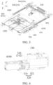
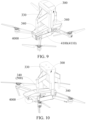
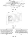
- a hangar 1000 for an unmanned aerial vehicle, a vehicle 2000, a control method, a control device 3000, and a computer-readable storage medium provided in embodiments of the present disclosure are described in detail below with reference to FIG. 1 to FIG. 24 .
- the vehicle 2000 provided in the embodiments of the present disclosure may be a sedan, a sport utility vehicle (SUV), a multi-purpose vehicle (MPV), a pickup truck, or the like, or may be a vehicle on which the hangar 1000 for an unmanned aerial vehicle can be mounted such as a fuel vehicle, a hybrid vehicle, or a pure electric vehicle.
- the hangar 1000 may be arranged on a roof 2100, a rear cargo cabin 2200, or a front cargo cabin 2300 of the vehicle 2000.
- the unmanned aerial vehicle takes off and lands in an environment without obstacles around, a good choice is to arrange the hangar 1000 on the roof 2100 of the vehicle 2000.
- the vehicle 2000 and the hangar 1000 are electrically and communicatively connected, so that the vehicle 2000 supplies power to the hangar 1000 and a driver can control the hangar 1000 in the vehicle 2000.
- the hangar 1000 includes a hangar body 100, a charging apparatus 200, and a battery pick-and-place apparatus 300.
- the hangar body 100 is configured to accommodate an unmanned aerial vehicle 4000.
- the charging apparatus 200 is arranged in the hangar body 100, and the charging apparatus 200 is configured to charge an unmanned aerial vehicle battery 4100.
- the unmanned aerial vehicle battery 4100 includes a first battery 4110 mounted on the unmanned aerial vehicle 4000 and/or a second battery 4120 outside the unmanned aerial vehicle 4000.
- the battery pick-and-place apparatus 300 is arranged in the hangar body 100, and the battery pick-and-place apparatus 300 is configured to detach the first battery 4110 from the unmanned aerial vehicle 4000 and/or mount the second battery 4120 into the unmanned aerial vehicle 4000.
- the first battery 4110 and the second battery 4120 are batteries of a same model, and both the first battery 4110 and the second battery 4120 are suitable for being mounted in the unmanned aerial vehicle 4000 and supplying power to the unmanned aerial vehicle 4000 during flight.
- the first battery 4110 and the second battery 4120 are definitions of the unmanned aerial vehicle battery 4100 at different positions.
- the unmanned aerial vehicle battery 4100 mounted on the unmanned aerial vehicle 4000 is the first battery 4110. After the unmanned aerial vehicle 4000 flies for a period of time, the first battery 4110 may be in a state of low power.
- the unmanned aerial vehicle battery 4100 located outside the unmanned aerial vehicle 4000 is the second battery 4120.
- the first battery 4110 with insufficient power can be detached via the battery pick-and-place apparatus 300 and the second battery 4120 with sufficient power can be mounted into the unmanned aerial vehicle 4000 in a process in which the unmanned aerial vehicle briefly returns to the hangar 1000 when the vehicle 2000 drives for a long time and the unmanned aerial vehicle needs to continuously follow the vehicle, thereby quickly extending the battery life time of the unmanned aerial vehicle 4000, so that the unmanned aerial vehicle 4000 continues to follow the vehicle.
- the unmanned aerial vehicle 4000 can be returned to the hangar 1000 for standby, and the unmanned aerial vehicle battery 4100 can be charged by the charging apparatus 200, thereby stably and sustainably meeting a battery life requirement of the unmanned aerial vehicle 4000 for following the vehicle next time, and there is no need to stop the vehicle or manually replace or charge the battery in the entire process.
- the battery pick-and-place apparatus 300 includes a clamping mechanism 310.
- the clamping mechanism 310 includes a first driving assembly 311 and two clamping members 312.
- the first driving assembly 311 is connected to at least one clamping member 312 to drive the at least one clamping member 312 to switch between a clamping state and a releasing state.
- the two clamping members 312 are suitable for clamping the unmanned aerial vehicle battery 4100, and when the clamping member 312 is in the releasing state, the two clamping members 312 are suitable for detaching from the unmanned aerial vehicle battery 4100.
- the clamping mechanism 310 drives the clamping members 312 to move through the first driving assembly 311, so that the clamping members 312 can switch between the clamping state and the releasing state. For example, when the battery pick-and-place apparatus 300 needs to detach the first battery 4110 on the unmanned aerial vehicle 4000, the clamping members 312 switch from the releasing state to the clamping state, and the clamping members 312 are clamped at corresponding positions of the first battery 4110, to implement disassembly of the first battery 4110.
- the first battery 4110 on the unmanned aerial vehicle 4000 or the second battery 4120 outside the unmanned aerial vehicle 4000 may be placed in the hangar body 100 or mounted on the unmanned aerial vehicle 4000 under clamping of the battery pick-and-place apparatus 300, to improve reliability of disassembly and assembly of the unmanned aerial vehicle battery 4100 on the unmanned aerial vehicle 4000 and reliability of disassembly and assembly of the unmanned aerial vehicle battery 4100 in the hangar body 100.
- the first driving assembly 311 includes a first driving member 311a.
- the first driving member 311a is configured to drive the at least one clamping member 312 to enable the two clamping members 312 to move toward each other, so that the clamping members 312 switch from the releasing state to the clamping state
- the first driving member 311a is configured to drive the at least one clamping member 312 to enable the two clamping members 312 to move away from each other, so that the clamping members 312 switch from the clamping state to the releasing state.
- the first driving assembly 311 includes the first driving member 311a and a reset member 311b.
- One of the first driving member 311a and the reset member 311b is configured to drive the at least one clamping member 312 to enable the two clamping members 312 to move toward each other, so that the clamping members 312 switch from the releasing state to the clamping state
- the other of the first driving member 311a and the reset member 311b is configured to drive the at least one clamping member 312 to enable the two clamping members 312 to move away from each other, so that the clamping members 312 switch from the clamping state to the releasing state.
- the first driving member 311a and the reset member 311b may also drive the two clamping members 312.
- clamping state and the releasing state are not specifically limited in the present disclosure.
- the clamping state and the releasing state should be relative concepts, that is, a state of clamping the unmanned aerial vehicle battery 4100 is the clamping state, and both a disengagement process before clamping and a disengagement process after clamping should be understood as the releasing state.
- both a process in which the first driving assembly 311 drives the at least one clamping member 312 to enable the two clamping members 312 to move away from each other or move toward each other to gradually open a clamping space for clamping the unmanned aerial vehicle battery 4100, and a process in which the two clamping members 312 move away from each other or move toward each other to gradually shrink the clamping space for clamping the unmanned aerial vehicle battery 4100 should be understood as the releasing state.
- the clamping member 312 switches to the clamping state.
- a manner in which the clamping members 312 clamp and fix the unmanned aerial vehicle battery 4100 may be providing a clamping groove on the unmanned aerial vehicle battery 4100, and the two clamping members 312 move away from each other until the two clamping members 312 are pushed against two sides of the clamping groove to fix the unmanned aerial vehicle battery 4100, or may be providing clamping grooves on the unmanned aerial vehicle battery 4100, and the two clamping members 312 respectively extend into the corresponding clamping groove.
- the unmanned aerial vehicle battery 4100 is clamped by the two clamping members 312 in a width direction, a length direction, or a height direction of the unmanned aerial vehicle battery 4100.
- the first driving member 311a includes a first power unit 311c and a first transmission unit 311d, and the first power unit 311c is connected to at least one clamping member 312 via the first transmission unit 311d.
- the reset member 311b includes a first elastic unit 311e, and the first elastic unit 311e is connected to the at least one clamping member 312.
- the first power unit 311c is a motor or a pressure pump.
- the first transmission unit 311d is one or more of a connecting rod mechanism, a gear mechanism, a thrust sliding mechanism, a hydraulic mechanism, a pneumatic mechanism, and a screw mechanism.
- the first elastic unit 311e is a spring.
- the battery pick-and-place apparatus 300 includes a lifting mechanism 320, and the lifting mechanism 320 is suitable for cooperating with a bottom surface of the unmanned aerial vehicle battery 4100 to support the unmanned aerial vehicle battery 4100.
- the unmanned aerial vehicle battery 4100 is generally constructed as a strip-shaped battery. In this case, an initial contact position between the battery pick-and-place apparatus 300 and the unmanned aerial vehicle battery 4100 may only be a side end portion of the unmanned aerial vehicle battery 4100 away from the unmanned aerial vehicle 4000. Because there is a specific distance between a center of gravity and the side end portion of the unmanned aerial vehicle battery 4100, if the battery pick-and-place apparatus 300 only applies a force to the side end portion of the unmanned aerial vehicle battery 4100, the unmanned aerial vehicle battery 4100 easily flips or slides around the side end portion.
- the lifting mechanism 320 is arranged on the battery pick-and-place apparatus 300, to cooperate with a bottom surface of the unmanned aerial vehicle battery 4100 and support the unmanned aerial vehicle battery 4100, so as to ensure stability of a posture of the unmanned aerial vehicle battery 4100 when the battery pick-and-place apparatus 300 picks and places the unmanned aerial vehicle battery 4100, and prevent the unmanned aerial vehicle battery 4100 from flipping or sliding, thereby improving accuracy of mounting, by the battery pick-and-place apparatus 300, the unmanned aerial vehicle battery 4100 into the unmanned aerial vehicle 4000 or the hangar body 100.
- the battery pick-and-place apparatus 300 further includes a base 330, and the clamping mechanism 310 and/or the lifting mechanism 320 are/is arranged on the base 330.
- the lifting mechanism 320 includes a lifting member 321.
- the lifting member 321 may switch between a protruding position suitable for cooperating with the bottom surface of the unmanned aerial vehicle battery 4100 and a retracted position below the base 330, to avoid the lifting mechanism 320 from interfering with other structures in the hangar 1000 when the unmanned aerial vehicle battery 4100 does not need to be supported.
- the lifting member 321 may also be always at the protruding position.
- the lifting mechanism 320 further includes a lifting push rod 322.
- the lifting push rod 322 is movably or retractably arranged on the base 330, and a free end of the lifting push rod 322 is connected to the lifting member 321 to drive the lifting member 321 to switch between the protruding position and the retracted position.
- the lifting member 321 is rotatably arranged on the lifting push rod 322, and when lifting the unmanned aerial vehicle battery 4100, the lifting member 321 is attached to a lower surface of the unmanned aerial vehicle battery 4100, and the lifting member 321 is tilted in a natural state.
- an axial hole or an adapter plate can be provided on the free end of the lifting push rod 322, the axial hole is provided on the adapter plate, and a rotating shaft is arranged on the lifting member 321. The rotating shaft is mounted to the axial hole, so that the lifting member 321 can rotate relative to the lifting push rod 322.
- the lifting member 321 can switch between an inclined position with an angle to a horizontal plane and a horizontal position substantially parallel to the horizontal plane.
- An angle between the lifting member 321 at the inclined position and the horizontal plane can range from 15° to 20°.
- FIG. 8 (b) in a process in which the lifting member 321 moves toward the unmanned aerial vehicle battery 4100 along with the lifting push rod 322 or the base 330, the lifting member 321 gradually comes into contact with the bottom surface of the unmanned aerial vehicle battery 4100, and flips from the inclined position to the horizontal position to lift the unmanned aerial vehicle battery 4100. As shown in FIG.
- the lifting member 321 in a process in which the lifting member 321 moves away from the unmanned aerial vehicle battery 4100 along with the lifting push rod 322 or the base 330, the lifting member 321 can gradually move away from the unmanned aerial vehicle battery 4100 and restore the inclined position.
- the lifting member 321 is set to a rotatable structure, to avoid a problem that the lifting member 321 cannot cooperate well with the bottom surface of the unmanned aerial vehicle battery 4100 due to misalignment with the bottom surface of the unmanned aerial vehicle battery 4100 in a battery pick-and-place process, thereby improving battery replacement stability of the battery pick-and-place apparatus 300.
- a buffer layer may be arranged on a side surface of the lifting member 321 facing the unmanned aerial vehicle battery 4100. Further, an anti-slip texture may be set on the buffer layer to improve stability of lifting the unmanned aerial vehicle battery 4100 and provide a buffer for the unmanned aerial vehicle battery 4100.
- the battery pick-and-place apparatus 300 includes a pressing mechanism 340, and the pressing mechanism 340 is suitable for cooperating with a top surface of the unmanned aerial vehicle 4000 to press a body of the unmanned aerial vehicle 4000.
- the unmanned aerial vehicle 4000 an opening of a battery mounting groove is provided at a top portion.
- the battery pick-and-place apparatus 300 needs to apply an upward force to the unmanned aerial vehicle battery 4100 when picking out the unmanned aerial vehicle battery 4100 from the unmanned aerial vehicle 4000.
- the body of the unmanned aerial vehicle 4000 may be lifted together with the unmanned aerial vehicle battery 4100, and there is a risk that the body of the unmanned aerial vehicle 4000 falls in this process.
- the pressing mechanism 340 is arranged on the battery pick-and-place apparatus 300, to press a top surface of the body of the unmanned aerial vehicle 4000 when the battery pick-and-place apparatus 300 picks out the unmanned aerial vehicle battery 4100 from the unmanned aerial vehicle 4000, thereby ensuring the stability of the posture of the unmanned aerial vehicle 4000 and preventing the unmanned aerial vehicle 4000 from falling and being damaged after being lifted.
- the pressing mechanism 340 there are at least two pressing mechanisms 340, and the at least two pressing mechanisms 340 are spaced apart from each other. Multiple pressing mechanisms 340 form multi-point pressing on the body of the unmanned aerial vehicle 4000, thereby improving stability of the pressing.
- the pressing mechanism 340 is arranged on the base 330, and the pressing mechanism 340 can move or retract in a vertical direction relative to the base 330.
- the pressing mechanism 340 has a spring piston structure. When the pressing mechanism 340 comes into contact with the body of the unmanned aerial vehicle 4000 and makes a spring of the pressing mechanism 340 in a compressed state, a pressing force is applied to the body of the unmanned aerial vehicle 4000.
- the hangar 1000 further includes a movable rack 400.
- the movable rack 400 is movably arranged in the hangar body 100, and the battery pick-and-place apparatus 300 is arranged on the movable rack 400.
- the battery pick-and-place apparatus 300 is arranged on the movable rack 400, so that the battery pick-and-place apparatus 300 drives, in a manner of movement, the first battery 4110 to be separated from the body of the unmanned aerial vehicle 4000 and drives the second battery 4120 to be mounted into the body of the unmanned aerial vehicle 4000.
- the movable rack 400 is movably arranged in the hangar body 100 along a first direction
- the battery pick-and-place apparatus 300 is movably arranged on the movable rack 400 along a second direction.
- the first direction is not parallel to the second direction, and both the first direction and the second direction have the component in the horizontal plane direction.
- a first movable guide rail 410 is arranged in the hangar body 100, the first movable guide rail 410 extends along the first direction, and the movable rack 400 is movably arranged on the first movable guide rail 410 along the first direction.
- a second movable guide rail 420 is arranged on the movable rack 400, the second movable guide rail 420 extends along the second direction, and the battery pick-and-place apparatus 300 is movably arranged on the second movable guide rail 420 along the second direction via the base 330.
- the first direction and the second direction are perpendicular to each other, and both the first direction and the second direction extend in the horizontal plane direction.
- the first direction is a front-rear direction of the hangar 1000
- the second direction is a left-right direction of the hangar 1000.
- the hangar 1000 further includes a power-on/off apparatus 500, and the power-on/off apparatus 500 is arranged in the hangar body 100.
- the power-on/off apparatus 500 is switchable between a trigger state and an avoidance state, when the power-on/off apparatus 500 is in the trigger state, the power-on/off apparatus 500 is suitable for pressing a power-on/off button of the unmanned aerial vehicle 4000, and when the power-on/off apparatus 500 is in the avoidance state, the power-on/off apparatus 500 is suitable for being separated from the power-on/off button or skips applying a force to the power-on/off button.
- the power-on/off button of the unmanned aerial vehicle 4000 may be a button that is responsible for both power-on and power-off, or may include a power-on button and a power-off button.
- the unmanned aerial vehicle can only be turned on and turned off by a user manually triggering the power-on/off button on the unmanned aerial vehicle. Therefore, if the unmanned aerial vehicle needs to meet a requirement of following the vehicle at any time, the unmanned aerial vehicle needs to be kept in a start-up standby state for a long time, which will affect a battery life capability of the unmanned aerial vehicle.
- the power-on/off apparatus 500 is arranged, so that a hard start can be performed by pressing the power-on/off button of the unmanned aerial vehicle 4000 when the unmanned aerial vehicle 4000 is required to operate, and a hard shutdown can be performed by pressing the power-on/off button of the unmanned aerial vehicle 4000 when the unmanned aerial vehicle 4000 is not required to operate, thereby avoiding unnecessary power consumption and improving the battery life capability of the unmanned aerial vehicle 4000.
- the pressing mechanism 340 may be formed as the power-on/off apparatus 500. That is, the battery pick-and-place apparatus 300 can enable, in a manner of movement, the pressing mechanism 340 to switch between the trigger state and the avoidance state.
- the pressing mechanism 340 is suitable for pressing the power-on/off button of the unmanned aerial vehicle 4000, and when the pressing mechanism 340 is in the avoidance state, the pressing mechanism 340 is suitable for being separated from the power-on/off button or skips applying a force to the power-on/off button.
- the power-on/off apparatus 500 is arranged on the base 330 of the battery pick-and-place apparatus 300 and moves with the base 330, so that the power-on/off apparatus 500 comes into contact with the power-on/off button of the unmanned aerial vehicle 4000 in a manner of movement to perform a hard start or a hard shutdown on the unmanned aerial vehicle 4000.
- the power-on/off apparatus 500 includes a trigger member 510, and a length of the trigger member 510 is retractable.
- the trigger member 510 can press the power-on/off button through extending movement and can be separated from the power-on/off button through shortening movement, or the trigger member 510 is movably arranged on the base 330, and the trigger member 510 can press the power-on/off button by moving close to the power-on/off button and can be separated from the power-on/off button by moving away from the power-on/off button.
- the trigger member 510 of the power-on/off apparatus 500 is set to be a retractable or movable structure, so that a contact manner between the power-on/off apparatus 500 and the power-on/off button of the unmanned aerial vehicle 4000 is more flexibly adjusted.
- the charging apparatus 200 includes a first charging apparatus 210.
- the first charging apparatus 210 is configured to charge the first battery 4110 mounted on the unmanned aerial vehicle 4000 by connecting to the unmanned aerial vehicle 4000 or the first battery 4110.
- the unmanned aerial vehicle 4000 can be returned to the hangar 1000 for standby, and the first charging apparatus 210 is directly electrically connected to the first battery 4110 on the unmanned aerial vehicle 4000 or the charging interface of the unmanned aerial vehicle 4000 to charge the first battery 4110 on the unmanned aerial vehicle 4000, thereby stably and sustainably meeting a battery life requirement of the unmanned aerial vehicle 4000 for following the vehicle next time.
- the hangar 1000 further includes a parking platform 600.
- the parking platform 600 is configured to allow parking of the unmanned aerial vehicle 4000.
- the first charging apparatus 210 includes an unmanned aerial vehicle rack 700 and an electrical connecting wire 211.
- the unmanned aerial vehicle rack 700 is mounted on the unmanned aerial vehicle 4000, can fly together with the unmanned aerial vehicle 4000, and is suitable for being parked on the parking platform 600 and supporting the unmanned aerial vehicle 4000.
- the electrical connecting wire 211 is arranged on the unmanned aerial vehicle rack 700, and a first fitting portion 211a and a second fitting portion 211b are arranged.
- the first fitting portion 211a is suitable for being electrically connected to the charging interface of the unmanned aerial vehicle 4000 or the first battery 4110
- the second fitting portion 211b is suitable for being electrically connected to the power supply interface 610 of the parking platform 600.
- the electrical connecting wire 211 can connect the power supply interface 610 of the parking platform 600 with the charging interface of the unmanned aerial vehicle 4000 or the first battery 4110, to implement automatic charging of the unmanned aerial vehicle 4000 on the parking platform 600, thereby eliminating an operation of charging the first battery 4110 and improving user experience.
- a wiring channel 710 is provided on the unmanned aerial vehicle rack 700, the wiring channel 710 extends to a bottom portion of the unmanned aerial vehicle rack 700, the electrical connecting wire 211 is arranged in the wiring channel 710, and the second fitting portion 211b is connected to the bottom portion of the unmanned aerial vehicle rack 700.
- the wiring channel 710 can be configured to fix the electrical connecting wire 211 and control a direction of the electrical connecting wire 211, to prevent the electrical connecting wire 211 from loosening and shaking.
- the wiring channel 710 can be provided on one side of the inside of the unmanned aerial vehicle rack 700, to reduce exposure of the electrical connecting wire 211 and implement hiding of the electrical connecting wire 211, which helps reduce an impact of the electrical connecting wire 211 on performance and aesthetics of the unmanned aerial vehicle 4000 and improve a service life of the electrical connecting wire 211.
- the second fitting portion 211b includes a contact convex point 211c, a contact groove 611 is provided on the power supply interface 610, and the contact convex point 211c is suitable for extending into the contact groove 611 to enable the second fitting portion 211b to be electrically connected to the power supply interface 610.
- a mounting channel (not shown in the figure) is provided in the second fitting portion 211b, a second elastic unit (not shown in the figure) is arranged in the mounting channel, the contact convex point 211c is at least partially arranged in the mounting channel and cooperates with the second elastic unit, and the second elastic unit applies a force toward the contact convex point 211c to enable the contact convex point 211c to have a tendency to extend out of the mounting channel.
- the contact convex point 211c can further enable the second elastic unit to be compressed under an impact of influence of gravity of the unmanned aerial vehicle 4000 and the unmanned aerial vehicle rack 700, and the contact convex point 211c retracts into the mounting channel, so that the unmanned aerial vehicle 4000 stops steadily.
- the contact convex point 211c can extend out of the mounting channel under the force of the second elastic unit and extend out of the mounting channel to abut against the contact groove 611, thereby improving reliability of an electrical connection between the contact convex point 211c and the contact groove 611 and avoiding a problem of false connection.
- the battery charging apparatus 200 includes the second charging apparatus 220.
- the second charging apparatus 220 is configured to charge the second battery 4120 outside the unmanned aerial vehicle 4000 by connecting to the second battery 4120.
- the second battery 4120 is continuously charged by being electrically connected to the second charging apparatus 220, so that the second battery 4120 can also be continuously charged during the flight of the unmanned aerial vehicle 4000.
- the first battery 4110 on the unmanned aerial vehicle 4000 is low on power
- the first battery 4110 can be replaced with the second battery 4120 with sufficient power, thereby stably and sustainably increasing the battery lifetime of the unmanned aerial vehicle 4000.
- the battery pick-and-place apparatus 300 is configured to connect the first battery 4110 to the second charging apparatus 220 after detaching the first battery 4110 from the unmanned aerial vehicle 4000, and mount the second battery 4120 into the unmanned aerial vehicle 4000 after picking out the second battery 4120 connected to the second charging apparatus 220.
- the second charging apparatus 220 includes multiple charging grooves 221, the charging grooves 221 are fixedly provided in the hangar body 100, insertion ports 221a are provided on the charging grooves 221, and the second battery 4120 is suitable for being inserted into the charging grooves 221 through the insertion ports 221a for charging.
- multiple through holes 221b for heat dissipation are provided on the charging grooves 221.
- multiple charging grooves 221 are provided side by side, and the insertion ports 221a of the multiple charging grooves 221 are oriented in a same direction, so that it is convenient for the battery pick-and-place apparatus 300 to place the unmanned aerial vehicle battery 4100 into the charging grooves 221 and pick out the unmanned aerial vehicle battery 4100 from the charging grooves 221.
- the insertion ports 221a of the multiple charging grooves 221 can be oriented toward a parking area of the unmanned aerial vehicle 4000, to shorten a moving distance of the battery pick-and-place apparatus 300 in a battery replacement process, thereby improving battery replacement efficiency.
- adjacent charging grooves 221 are spaced apart to improve a heat dissipation effect; or adjacent charging grooves 221 are closely provided, to improve spatial compactness of the hangar 1000.
- the insertion ports 221a of the multiple charging grooves 221 may also be oriented toward a direction away from the parking area of the unmanned aerial vehicle 4000.
- multiple charging grooves 221 are circumferentially spaced apart around a vertical axis, and the insertion ports 221a of the multiple charging grooves 221 are oriented away from the vertical axis.
- the insertion ports 221a of the multiple charging grooves 221 face outward, so that it is convenient for the battery pick-and-place apparatus 300 to place the unmanned aerial vehicle battery 4100 into the charging grooves 221.
- the multiple charging grooves 221 may be provided on a rotating platform 222.
- the rotating platform 222 is rotatably arranged in the hangar body 100 around a vertical axis.
- the rotating platform 222 is rotated, so that when the battery pick-and-place apparatus 300 picks out the first battery 4110 from the unmanned aerial vehicle 4000, the insertion ports 221a of the charging grooves 221 that are not connected to the unmanned aerial vehicle battery 4100 can be rotated to face the unmanned aerial vehicle 4000. Then the battery pick-and-place apparatus 300 mounts the first battery 4110 into the charging grooves 221, and then rotates the insertion ports 221a of the charging grooves 221 connected to the second battery 4120 with sufficient power to face the unmanned aerial vehicle 4000.
- the battery pick-and-place apparatus 300 picks out the second battery 4120 from the charging grooves 221 and mounts the second battery 4120 into the unmanned aerial vehicle 4000, thereby greatly shortening the moving distance of the battery pick-and-place apparatus 300 in the battery replacement process.
- the hangar 1000 further includes a centering apparatus 800, and the centering apparatus 800 is arranged in the hangar body 100.
- the centering apparatus 800 is suitable for pushing the unmanned aerial vehicle 4000 to the target position and fixing the unmanned aerial vehicle 4000 at the target position.
- the battery pick-and-place apparatus 300 is configured to detach the first battery 4110 from the unmanned aerial vehicle 4000 located at the target position and/or mount the second battery 4120 into the unmanned aerial vehicle 4000 located at the target position.
- a position of the first battery 4110 on the unmanned aerial vehicle 4000 is abstracted as coordinates, and the coordinates are set as a mobile node of the battery pick-and-place apparatus 300, so that a control strategy can be greatly simplified.
- the centering apparatus 800 is arranged, to push the unmanned aerial vehicle 4000 back to the target position and fix the unmanned aerial vehicle 4000 at the target position, so that the battery pick-and-place apparatus 300 can be controlled through a simple control strategy to successfully complete the battery replacement.
- the coordinates of the unmanned aerial vehicle 4000 corresponding to the set target position can also be used to ensure that the first charging apparatus 210 is successfully electrically connected to the unmanned aerial vehicle 4000 or the first battery 4110 through the simple control strategy, and to ensure that the power-on/off apparatus 500 successfully presses the power-on/off button of the unmanned aerial vehicle 4000 through the simple control strategy.
- the centering apparatus 800 includes multiple pushing assemblies 810 and a second driving assembly 820.
- the second driving assembly 820 is connected to each of the pushing assemblies 810 to drive the pushing assemblies 810 to push the unmanned aerial vehicle 4000, and when pushing the unmanned aerial vehicle 4000, the pushing assemblies 810 apply pushing forces in different directions to the unmanned aerial vehicle 4000, to push the unmanned aerial vehicle 4000 to the target position and fix the unmanned aerial vehicle at the target position.
- propulsion forces in multiple different directions can not only adjust the orientation of the unmanned aerial vehicle 4000, but also push the unmanned aerial vehicle 4000 to the target position.
- a quantity of pushing assemblies 810 is at least three, and each pushing assembly 810 includes a pushing member 811.
- a first pushing edge 811a is arranged on the pushing member 811, and the first pushing edges 811a of the multiple pushing members 811 form a polygon.
- An unmanned aerial vehicle rack 700 is arranged at a bottom portion of the unmanned aerial vehicle 4000, and the unmanned aerial vehicle rack 700 is suitable for being parked in the hangar body 100 and supporting the unmanned aerial vehicle 4000.
- Multiple second pushing edges 720 are formed on outer edges of the unmanned aerial vehicle rack 700, and the second pushing edges 720 are suitable for being in a one-to-one correspondence with and cooperating with the first pushing edges 811a.
- a quantity of pushing members 811 is four, the first pushing edges 811a of the four pushing members 811 form a rectangle, and the outer edges of the unmanned aerial vehicle rack 700 form a rectangle.
- the second driving assembly 820 includes a second driving member 821.
- the second driving member 821 drives the pushing assemblies 810.
- the second driving assembly 820 further includes a locking member (not shown in the figure), and when the pushing assemblies 810 need to fix the unmanned aerial vehicle 4000, the locking member applies a locking force to the pushing assemblies 810.
- the second driving member 821 includes a second power unit 821a and a second transmission unit 821b, and the second power unit 821a is connected to each of the pushing assemblies 810 via the second transmission unit 821b.
- the second power unit 821a is a motor or a pressure pump.
- the second transmission unit 821b is one or more of a connecting rod mechanism, a gear mechanism, a thrust sliding mechanism, a hydraulic mechanism, a pneumatic mechanism, and a screw mechanism.
- a locking member is a locking motor connected to the second transmission unit 821b.
- the first pushing edges 811a form a first pushing slope (not shown in the figure) facing downward
- the second pushing edges 720 form a second pushing slope (not shown in the figure) facing upward
- the first pushing slope is suitable for cooperating with the corresponding second pushing slope.
- the hangar body 100 includes a cabin door 110, a cabin body 120, and a cabin door opening and closing apparatus (not shown in the figure), and the cabin body 120 includes an unmanned aerial vehicle entrance and exit 121.
- the cabin door 110 is connected to the cabin body 120 via the cabin door opening and closing apparatus, and the cabin door opening and closing apparatus is configured to drive the cabin door 110 to switch between an open state and a closed state.
- the cabin door 110 closes the unmanned aerial vehicle entrance and exit 121; and when the cabin door 110 is in the open state, the cabin door 110 avoids the unmanned aerial vehicle entrance and exit 121 to allow the unmanned aerial vehicle entrance and exit 121 to be opened.
- the unmanned aerial vehicle entrance and exit 121 is formed at a top portion of the cabin body 120, or the unmanned aerial vehicle entrance and exit 121 is formed at a tail portion of the cabin body 120.
- the hangar 1000 further includes a parking platform 600.
- the parking platform 600 is configured to allow parking of the unmanned aerial vehicle 4000, and the parking platform 600 is movably arranged in the hangar body 100. Because the existing unmanned aerial vehicle needs to take off or land in an environment with no obstacles around, the parking platform 600 is set to be movable. When the unmanned aerial vehicle 4000 needs to take off or land, the unmanned aerial vehicle can be moved to an environment with no obstacles around by moving the parking platform 600.
- the parking platform 600 is set to be movable in an ascending or descending manner so that the unmanned aerial vehicle 4000 is transported out of the hangar body 100 through the unmanned aerial vehicle entrance and exit 121.
- the parking platform 600 is set to be horizontally movable so that the unmanned aerial vehicle 4000 is transported out of the hangar body 100 through the unmanned aerial vehicle entrance and exit 121.
- an electromagnet is arranged on the parking platform 600.
- the electromagnet can be energized to temporarily attract the unmanned aerial vehicle 4000 onto the parking platform 600, and the electromagnet can be de-energized after the parking platform 600 returns to the hangar body 100.
- the hangar 1000 further includes a heat dissipation apparatus 900.
- the heat dissipation apparatus 900 is arranged in the hangar body 100, and the heat dissipation apparatus 900 is configured to perform heat dissipation on an internal space of the hangar body 100.
- the hangar body 100 is in a closed state, and the hangar 1000 is arranged on the vehicle 2000 and may be exposed to the sun for a long time when the vehicle is driving. This easily causes the hangar body 100 to reach a high temperature, which is not conducive to placement of the unmanned aerial vehicle 4000, the unmanned aerial vehicle battery 4100, and other electrical devices.
- the heat dissipation apparatus 900 provided in the embodiments of the present disclosure can effectively reduce a temperature in the hangar body 100.
- the heat dissipation apparatus 900 includes a heat dissipation fan 910, and a heat dissipation vent corresponding to the heat dissipation fan 910 is provided in the hangar body 100.
- the control method for a hangar 1000 for an unmanned aerial vehicle includes the following step S101 and step S102.
- a battery pick-and-place apparatus 300 is controlled to perform battery replacement on the unmanned aerial vehicle 4000, thereby quickly extending battery life time of the unmanned aerial vehicle 4000.
- a charging apparatus 200 includes a first charging apparatus 210 and a second charging apparatus 220. If the first preset condition is met, the battery pick-and-place apparatus 300 is controlled to detach the first battery 4110 on the unmanned aerial vehicle 4000 from the unmanned aerial vehicle 4000 and connect the first battery 4110 to the second charging apparatus 220, and the second battery 4120 connected to the second charging apparatus 220 is picked out and the second battery 4120 is mounted into the unmanned aerial vehicle 4000.
- the first preset condition may include: The unmanned aerial vehicle 4000 is located at a target position in a hangar body 100; and the hangar 1000 receives a battery replacement signal, for example, a driver actively sends a battery replacement instruction to the hangar 1000, or a remaining power of the first battery 4110 is less than a first threshold and the hangar 1000 does not receive an unmanned aerial vehicle shutdown signal.
- a controller of the hangar 1000 or the vehicle 2000 determines that the remaining power of the first battery 4110 on the unmanned aerial vehicle 4000 no longer meets a requirement for continued flying, and the driver has no intention to stop the unmanned aerial vehicle from continuing to fly, the hangar 1000 may actively perform a battery replacement operation.
- the first preset condition when the first preset condition is met, it may be considered that there is a requirement to allow the unmanned aerial vehicle 4000 to briefly return to the hangar 1000 for battery replacement.
- the charging apparatus 200 is controlled to directly and continuously charge the first battery 4110 on the unmanned aerial vehicle 4000, thereby stably and sustainably extending battery life time of the unmanned aerial vehicle 4000.
- the charging apparatus 200 includes the first charging apparatus 210 and the second charging apparatus 220. If the second preset condition is met, the first charging apparatus 210 is controlled to be electrically connected to the unmanned aerial vehicle 4000 or the first battery 4110 on the unmanned aerial vehicle 4000 to charge the first battery 4110.
- the second preset condition may include: The unmanned aerial vehicle 4000 is located at the target position in the hangar body 100; and the hangar 1000 receives an unmanned aerial vehicle battery start charging signal, that is, the hangar 1000 can actively request the charging apparatus 200 to charge the first battery 4110 on the unmanned aerial vehicle 4000, or the hangar 1000 does not receive an unmanned aerial vehicle battery stop charging signal, that is, even if no charging requirement is received, if the unmanned aerial vehicle 4000 is located at the target position in the hangar body 100, the charging apparatus 200 may be allowed to charge the first battery 4110 on the unmanned aerial vehicle 4000 by default.
- the second preset condition when the second preset condition is met, it may be considered that there is a requirement to allow the unmanned aerial vehicle 4000 to stop continuing to fly and return to the hangar 1000 for parking or standby.
- the first battery 4110 with insufficient power can be detached via the battery pick-and-place apparatus 300 and the second battery 4120 with sufficient power can be mounted into the unmanned aerial vehicle 4000 in a process in which the unmanned aerial vehicle briefly returns to the hangar 1000 when the vehicle 2000 drives for a long time and the unmanned aerial vehicle needs to continuously follow the vehicle, thereby quickly extending the battery life time of the unmanned aerial vehicle 4000, so that the unmanned aerial vehicle 4000 continues to follow the vehicle.
- the unmanned aerial vehicle 4000 can be returned to the hangar 1000 for standby, and the unmanned aerial vehicle battery 4100 can be charged by the charging apparatus 200, thereby stably and sustainably meeting a battery life requirement of the unmanned aerial vehicle 4000 for following the vehicle next time, and there is no need to stop the vehicle or manually replace or charge the battery in the entire process.
- the control method for a hangar 1000 for an unmanned aerial vehicle provided in the embodiments of the present disclosure further includes step S103.
- the control method for a hangar 1000 for an unmanned aerial vehicle provided in the embodiments of the present disclosure further includes step S104 and step S105.
- S104 After the hangar receives the unmanned aerial vehicle take-off preparation signal or an unmanned aerial vehicle landing completion signal, control a cabin door opening and closing apparatus to drive a cabin door to switch from a closed state for closing an unmanned aerial vehicle entrance and exit to an open state for avoiding the unmanned aerial vehicle entrance and exit.
- the cabin door opening and closing apparatus is controlled to enable the cabin door 110 to close the unmanned aerial vehicle entrance and exit 121, to ensure stability of the hangar 1000 during driving of the vehicle 2000; and when the unmanned aerial vehicle 4000 needs to pass through the unmanned aerial vehicle entrance and exit 121, the cabin door opening and closing apparatus is controlled to enable the cabin door 110 to open the unmanned aerial vehicle entrance and exit 121.
- the control method for a hangar 1000 for an unmanned aerial vehicle provided in the embodiments of the present disclosure further includes step S106 and step S107.
- a height of the first preset position is greater than a height of the second preset position. Because the existing unmanned aerial vehicle needs to take off or land in an environment with no obstacles around, the parking platform 600 is moved from the height of the second preset position covered by the hangar 1000 to the height of the first preset position that is higher than the hangar 1000. When the unmanned aerial vehicle 4000 needs to take off or land, the unmanned aerial vehicle can be moved to an environment with no obstacles around by moving the parking platform 600.
- the control method for a hangar 1000 for an unmanned aerial vehicle provided in the embodiments of the present disclosure further includes step S108 and step S109.
- the unmanned aerial vehicle 4000 when the unmanned aerial vehicle 4000 needs to take off from the hangar 1000, a restraint on the unmanned aerial vehicle by the centering apparatus 800 needs to be released, to create conditions for the take-off of the unmanned aerial vehicle 4000; and when the unmanned aerial vehicle 4000 needs to return to the hangar 1000, the unmanned aerial vehicle 4000 needs to be fixed at the target position via the centering apparatus 800, to prevent the unmanned aerial vehicle 4000 from shaking in the hangar 1000 when the vehicle 2000 is driving, thereby providing stable conditions for the battery replacement of the battery pick-and-place apparatus 300.
- the control method for a hangar 1000 for an unmanned aerial vehicle provided in the embodiments of the present disclosure further includes step S110.
- the driver can actively issue a heat dissipation instruction to the hangar 1000, or if a controller of the hangar 1000 or the vehicle 2000 determines that the internal temperature of the hangar 1000 is too high, the hangar 1000 can actively perform a heat dissipation operation.
- the control method for a hangar 1000 for an unmanned aerial vehicle may include step S201 to step S232.
- a take-off process of an unmanned aerial vehicle 4000 includes step S201 to step S206.
- step S201 Determine whether a hangar receives an unmanned aerial vehicle take-off preparation signal, if yes, perform step S202, and if not, end.
- step S202 Determine whether an unmanned aerial vehicle is in a power-off state, if yes, perform step S203, and if not, perform step S204.
- step S205 Control a parking platform to move to a first preset position, and then perform step S206.
- step S207 Determine whether the hangar receives an unmanned aerial vehicle take-off completion signal, if not, continue to perform step S207, and if yes, perform step S208.
- S209 Control the cabin door opening and closing apparatus to drive the cabin door to switch from the open state for avoiding the unmanned aerial vehicle entrance and exit to the closed state for closing the unmanned aerial vehicle entrance and exit.
- a process of short return for battery replacement of the unmanned aerial vehicle 4000 includes step S210 to step S223.
- step S210 Determine whether a hangar receives an unmanned aerial vehicle landing preparation signal, if yes, perform step S211, and if not, end.
- step S211 Control the cabin door opening and closing apparatus to drive a cabin door to switch from the closed state for closing the unmanned aerial vehicle entrance and exit to the open state for avoiding the unmanned aerial vehicle entrance and exit, and then perform step S212.
- step S213 Determine whether the hangar receives an unmanned aerial vehicle landing completion signal, if not, continue to perform step S213, and if yes, perform step S214.
- S215 Control the cabin door opening and closing apparatus to drive the cabin door to switch from the open state for avoiding the unmanned aerial vehicle entrance and exit to the closed state for closing the unmanned aerial vehicle entrance and exit, and then perform step S216.
- S217 Control a battery pick-and-place apparatus to detach a first battery on the unmanned aerial vehicle from the unmanned aerial vehicle and connect the first battery to a second charging apparatus, and pick out a second battery connected to the second charging apparatus and mount the second battery into the unmanned aerial vehicle, and then perform step S218.
- step S219 Control the parking platform to move to the first preset position, and then perform step S220.
- step S221 Determine whether the hangar receives an unmanned aerial vehicle take-off completion signal, if not, continue to perform step S221, and if yes, perform step S222.
- S223 Control the cabin door opening and closing apparatus to drive the cabin door to switch from the open state for avoiding the unmanned aerial vehicle entrance and exit to the closed state for closing the unmanned aerial vehicle entrance and exit.
- a process in which the unmanned aerial vehicle 4000 stops operating and is recovered includes step S218 to step S223.
- S226 Control the parking platform to move to the first preset position, and then perform step S227.
- step S227 Determine whether the hangar receives the unmanned aerial vehicle landing completion signal, if not, continue to perform step S227, and if yes, perform step S228.
- S229 Control the cabin door opening and closing apparatus to drive the cabin door to switch from the open state for avoiding the unmanned aerial vehicle entrance and exit to the closed state for closing the unmanned aerial vehicle entrance and exit, and then perform step S230.
- step S230 Control the centering apparatus to push the unmanned aerial vehicle to the target position and fix the unmanned aerial vehicle at the target position, and then perform step S231.
- step S231 Control the power-on/off apparatus to press the power-on/off button of the unmanned aerial vehicle to close the unmanned aerial vehicle, and then perform step S232.
- S232 Control the first charging apparatus to be electrically connected to the unmanned aerial vehicle or the first battery on the unmanned aerial vehicle to charge the first battery.
- embodiments of the present disclosure further provide a control device 3000 for a hangar 1000 for an unmanned aerial vehicle, including a processor 3100 and a memory 3200.
- the processor 3100 and the memory 3200 are connected to each other.
- the memory 3200 is configured to store a computer program.
- the computer program includes program instructions, and the processor 3100 is configured to invoke the program instructions, to perform the control method provided in the embodiments of the present disclosure.
- Embodiments of the present disclosure further provide a computer-readable storage medium.
- the computer-readable storage medium stores a computer program.
- the control method provided in the embodiments of the present disclosure is implemented.
- the computer-readable storage medium may be an internal storage unit of a task processing apparatus provided in any one of the foregoing embodiments, for example, a hard disk or an internal memory of the electronic device.
- the computer-readable storage medium may also be an external storage device of the electronic device, such as a plug-in hard disk, a smart media card (SMC), a secure digital (SD) card, or a flash card that is equipped on the electronic device.
- the computer-readable storage medium may further include a magnetic disk, an optical disc, a read-only memory (ROM), a random access memory (RAM), or the like.
- the computer-readable storage medium may further include an internal storage unit of the electronic device and an external storage device.
- the computer-readable storage medium is configured to store the computer program and another program and data that are required by the electronic device.
- the computer-readable storage medium may be further configured to temporarily store data that has been output or data to be output.
Landscapes
- Engineering & Computer Science (AREA)
- Transportation (AREA)
- Mechanical Engineering (AREA)
- Aviation & Aerospace Engineering (AREA)
- Remote Sensing (AREA)
- Power Engineering (AREA)
- Architecture (AREA)
- Robotics (AREA)
- Public Health (AREA)
- Health & Medical Sciences (AREA)
- Chemical & Material Sciences (AREA)
- Combustion & Propulsion (AREA)
- Civil Engineering (AREA)
- Structural Engineering (AREA)
- Charge And Discharge Circuits For Batteries Or The Like (AREA)
- Forklifts And Lifting Vehicles (AREA)
- Control Of Position, Course, Altitude, Or Attitude Of Moving Bodies (AREA)
Abstract
Description
- The present disclosure is proposed based on and claims priority to
Chinese Patent Application No. 202210855166.6, filed on July 19, 2022 - The present disclosure belongs to the field of unmanned aerial vehicle devices, and in particular, to a hangar for an unmanned aerial vehicle, a vehicle, and a control method.
- A hangar for an unmanned aerial vehicle in the related art can be transported to a designated location by a vehicle, and then releases the unmanned aerial vehicle to perform related work. When a battery life of the unmanned aerial vehicle is insufficient, the unmanned aerial vehicle is recovered and the battery lifetime is supplemented by manual battery replacement or charging.
- However, for an unmanned aerial vehicle that needs to follow a vehicle while the vehicle is driving, the unmanned aerial vehicle cannot be charged manually without stopping the vehicle. In addition, because driving time of the vehicle may be long or short, it is difficult to ensure that the battery lifetime of the unmanned aerial vehicle can cover the driving time of the vehicle as much as possible.
- To resolve the foregoing technical problems, the present disclosure provides a hangar for an unmanned aerial vehicle, which can extend battery lifetime of the unmanned aerial vehicle by replacing batteries to adapt to a long-time driving scenario of a vehicle, and can also extend the battery lifetime of the unmanned aerial vehicle by charging to adapt to a scenario in which the vehicle finishes short-time driving, or the vehicle is parked, or the unmanned aerial vehicle does not need to follow the vehicle, thereby ensuring that the battery lifetime of the unmanned aerial vehicle can cover driving time of the vehicle as much as possible, to meet a requirement of following the vehicle.
- A specific technical solution of the present disclosure is as follows.
- A hangar for an unmanned aerial vehicle, suitable for being arranged on a vehicle, including:
- a hangar body, where the hangar body is configured to accommodate the unmanned aerial vehicle;
- a charging apparatus, where the charging apparatus is arranged in the hangar body, and the charging apparatus is configured to charge an unmanned aerial vehicle battery, where the unmanned aerial vehicle battery includes a first battery mounted on the unmanned aerial vehicle and/or a second battery outside the unmanned aerial vehicle; and
- a battery pick-and-place apparatus, where the battery pick-and-place apparatus is arranged in the hangar body, and the battery pick-and-place apparatus is configured to detach the first battery from the unmanned aerial vehicle and/or mount the second battery into the unmanned aerial vehicle.
- According to the hangar for an unmanned aerial vehicle provided in the present disclosure, the first battery with insufficient power can be detached via the battery pick-and-place apparatus and the second battery with sufficient power can be mounted into the unmanned aerial vehicle in a process in which the unmanned aerial vehicle briefly returns to the hangar when the vehicle drives for a long time and the unmanned aerial vehicle has a requirement to continuously follow the vehicle, thereby quickly extending the battery life time of the unmanned aerial vehicle, so that the unmanned aerial vehicle continues to follow the vehicle. After the vehicle finishes short-time driving, or when the vehicle is parked, or when the unmanned aerial vehicle does not need to follow the vehicle, the unmanned aerial vehicle can be returned to the hangar for standby, and the unmanned aerial vehicle battery can be charged by the charging apparatus, thereby stably and sustainably meeting a battery life requirement of the unmanned aerial vehicle for following the vehicle next time.
- In addition, the hangar for an unmanned aerial vehicle provided in the present disclosure may further have the following additional technical features.
- In some examples of the present disclosure, the battery pick-and-place apparatus includes a clamping mechanism. The clamping mechanism includes a first driving assembly and two clamping members. The first driving assembly is connected to at least one clamping member to drive the at least one clamping member to switch between a clamping state and a releasing state, when the clamping members are in the clamping state, the two clamping members are suitable for clamping the unmanned aerial vehicle battery, and when the clamping members are in the releasing state, the two clamping members are suitable for detaching from the unmanned aerial vehicle battery.
- In some examples of the present disclosure, the battery pick-and-place apparatus includes a lifting mechanism, and the lifting mechanism is suitable for cooperating with a bottom surface of the unmanned aerial vehicle battery to support the unmanned aerial vehicle battery.
- In some examples of the present disclosure, the hangar further includes a movable rack. The movable rack is movably arranged in the hangar body along a first direction, and the battery pick-and-place apparatus is movably arranged on the movable rack along a second direction. The first direction is not parallel to the second direction, and both the first direction and the second direction have the component in the horizontal plane direction.
- In some examples of the present disclosure, the hangar further includes a power-on/off apparatus. The power-on/off apparatus is arranged in the hangar body. The power-on/off apparatus is switchable between a trigger state and an avoidance state. When the power-on/off apparatus is in the trigger state, the power-on/off apparatus is suitable for pressing a power-on/off button of the unmanned aerial vehicle, and when the power-on/off apparatus is in the avoidance state, the power-on/off apparatus is suitable for being separated from the power-on/off button or skips applying a force to the power-on/off button.
- In some examples of the present disclosure, the hangar further includes the movable rack. The movable rack is movably arranged in the hangar body along the first direction, and both the power-on/off apparatus and the battery pick-and-place apparatus are movably arranged on the movable rack along the second direction. The first direction is not parallel to the second direction, and both the first direction and the second direction have the component in the horizontal plane direction.
- In some examples of the present disclosure, the charging apparatus includes a first charging apparatus, and the first charging apparatus is configured to charge, by connecting to the unmanned aerial vehicle or the first battery, the first battery mounted on the unmanned aerial vehicle.
- In some examples of the present disclosure, the hangar further includes a parking platform. The parking platform is configured to allow parking the unmanned aerial vehicle. The first charging apparatus includes an unmanned aerial vehicle rack and an electrical connecting wire. The unmanned aerial vehicle rack is mounted on the unmanned aerial vehicle, and the unmanned aerial vehicle rack is suitable for being parked on the parking platform and supporting the unmanned aerial vehicle. The electrical connecting wire is arranged on the unmanned aerial vehicle rack. A first fitting portion and a second fitting portion are arranged on the electrical connecting wire, the first fitting portion is suitable for being electrically connected to a charging interface of the unmanned aerial vehicle or the first battery, and the second fitting portion is suitable for being electrically connected to a power supply interface of the parking platform.
- In some examples of the present disclosure, a wiring channel is provided on the unmanned aerial vehicle rack, the wiring channel extends to a bottom portion of the unmanned aerial vehicle rack, the electrical connecting wire is arranged in the wiring channel, and the second fitting portion is connected to the bottom portion of the unmanned aerial vehicle rack.
- In some examples of the present disclosure, the second fitting portion includes a contact convex point, a contact groove is provided on the power supply interface, and the contact convex point is suitable for extending into the contact groove to enable the second fitting portion to be electrically connected to the power supply interface. A mounting channel is provided in the second fitting portion, a second elastic unit is arranged in the mounting channel, the contact convex point is at least partially arranged in the mounting channel and cooperates with the second elastic unit, and the second elastic unit applies a force toward the contact convex point to enable the contact convex point to have a tendency to extend out of the mounting channel.
- In some examples of the present disclosure, the charging apparatus includes a second charging apparatus, and the second charging apparatus is configured to charge the second battery outside the unmanned aerial vehicle by connecting to the second battery.
- In some examples of the present disclosure, the battery pick-and-place apparatus is further configured to connect the first battery to the second charging apparatus after detaching the first battery from the unmanned aerial vehicle, and/or mount the second battery into the unmanned aerial vehicle after picking out the second battery connected to the second charging apparatus.
- In some examples of the present disclosure, the second charging apparatus includes multiple charging grooves, the charging grooves are fixedly provided in the hangar body, insertion ports are provided on the charging grooves, and the second battery is suitable for being inserted into the charging grooves through the insertion ports for charging. The multiple charging grooves are provided side by side, and the insertion ports of the multiple charging grooves are oriented in a same direction; among the multiple charging grooves, adjacent charging grooves are spaced apart or are provided close to each other; or the multiple charging grooves are circumferentially arranged at intervals around a vertical axis, and the insertion ports of the multiple charging grooves are oriented away from the vertical axis.
- In some examples of the present disclosure, the hangar further includes a centering apparatus. The centering apparatus is arranged in the hangar body, and the centering apparatus is suitable for pushing the unmanned aerial vehicle to a target position and fixing the unmanned aerial vehicle at the target position. The battery pick-and-place apparatus is configured to detach the first battery from the unmanned aerial vehicle located at the target position and/or mount the second battery into the unmanned aerial vehicle located at the target position.
- In some examples of the present disclosure, the centering apparatus includes multiple pushing assemblies and a second driving assembly; and the second driving assembly is connected to each of the pushing assemblies to drive the pushing assemblies to push the unmanned aerial vehicle, and when pushing the unmanned aerial vehicle, the pushing assemblies apply pushing forces in different directions to the unmanned aerial vehicle, to push the unmanned aerial vehicle to the target position and fix the unmanned aerial vehicle at the target position.
- In some examples of the present disclosure, the hangar body includes a cabin door, a cabin body, and a cabin door opening and closing apparatus, and the cabin body includes an unmanned aerial vehicle entrance and exit. The cabin door is connected to the cabin body via the cabin door opening and closing apparatus, and the cabin door opening and closing apparatus is configured to drive the cabin door to switch between an open state and a closed state. When the cabin door is in the closed state, the cabin door closes the unmanned aerial vehicle entrance and exit; and when the cabin door is in the open state, the cabin door avoids the unmanned aerial vehicle entrance and exit to allow the unmanned aerial vehicle entrance and exit to be opened.
- In some examples of the present disclosure, the unmanned aerial vehicle entrance and exit is formed at a top portion of the cabin body, or the unmanned aerial vehicle entrance and exit is formed at a tail portion of the cabin body.
- In some examples of the present disclosure, the hangar further includes a parking platform. The parking platform is configured to allow parking of the unmanned aerial vehicle, and the parking platform is movably arranged in the hangar body.
- In some examples of the present disclosure, the hangar further includes a heat dissipation apparatus. The heat dissipation apparatus is arranged in the hangar body, and the heat dissipation apparatus is configured to perform heat dissipation on an internal space of the hangar body.
- The present disclosure further provides a vehicle, equipped with the hangar for an unmanned aerial vehicle provided in the present disclosure.
- The vehicle provided in the present disclosure may implement the following: The first battery with insufficient power can be detached via the battery pick-and-place apparatus and the second battery with sufficient power can be mounted into the unmanned aerial vehicle in a process in which the unmanned aerial vehicle briefly returns to the hangar when the vehicle drives for a long time and the unmanned aerial vehicle has a requirement to continuously follow the vehicle, thereby quickly extending the battery life time of the unmanned aerial vehicle, so that the unmanned aerial vehicle continues to follow the vehicle. After the vehicle finishes short-time driving, or when the vehicle is parked, or when the unmanned aerial vehicle does not need to follow the vehicle, the unmanned aerial vehicle can be returned to the hangar for standby, and the unmanned aerial vehicle battery can be charged by the charging apparatus, thereby stably and sustainably meeting a battery life requirement of the unmanned aerial vehicle for following the vehicle next time.
- The present disclosure further provides a control method for a hangar for an unmanned aerial vehicle. The hangar is the hangar provided in embodiments of the present disclosure. The control method includes: When a first preset condition is met, a battery pick-and-place apparatus is controlled to detach a first battery on the unmanned aerial vehicle from the unmanned aerial vehicle, and a second battery is mounted outside the unmanned aerial vehicle into the unmanned aerial vehicle; and when a second preset condition is met, a charging apparatus is controlled to be electrically connected to the unmanned aerial vehicle or the first battery on the unmanned aerial vehicle to charge the first battery.
- In some examples of the present disclosure, the charging apparatus includes a first charging apparatus and a second charging apparatus, the first charging apparatus is configured to charge, by connecting to the unmanned aerial vehicle or the first battery, the first battery mounted on the unmanned aerial vehicle, and the second charging apparatus is configured to charge the second battery outside the unmanned aerial vehicle by connecting to the second battery; that when the first preset condition is met, the battery pick-and-place apparatus is controlled to detach the first battery on the unmanned aerial vehicle from the unmanned aerial vehicle, and the second battery is mounted outside the unmanned aerial vehicle into the unmanned aerial vehicle includes: When the first preset condition is met, the battery pick-and-place apparatus is controlled to detach the first battery on the unmanned aerial vehicle from the unmanned aerial vehicle and connect the first battery to the second charging apparatus, and the second battery connected to the second charging apparatus is picked out and the second battery is mounted into the unmanned aerial vehicle; and that when the second preset condition is met, the charging apparatus is controlled to be electrically connected to the unmanned aerial vehicle or the first battery on the unmanned aerial vehicle to charge the first battery includes: When the second preset condition is met, the first charging apparatus is controlled to be electrically connected to the unmanned aerial vehicle or the first battery on the unmanned aerial vehicle to charge the first battery.
- In some examples of the present disclosure, the first preset condition includes: a target position in a hangar body at which the unmanned aerial vehicle is located; and the hangar receives a battery replacement signal, or a remaining power of the first battery is less than a first threshold and the hangar does not receive an unmanned aerial vehicle shutdown signal; and/or the second preset condition includes: the target position in the hangar body at which the unmanned aerial vehicle is located; and the hangar receives an unmanned aerial vehicle battery start charging signal, or the hangar does not receive an unmanned aerial vehicle battery stop charging signal.
- In some examples of the present disclosure, the hangar further includes a power-on/off apparatus; and the control method further includes: After the hangar receives an unmanned aerial vehicle power-on signal, an unmanned aerial vehicle power-off signal, an unmanned aerial vehicle take-off preparation signal, or an unmanned aerial vehicle landing completion signal, the power-on/off apparatus is controlled to press a power-on/off button of the unmanned aerial vehicle.
- In some examples of the present disclosure, the hangar body includes a cabin door, a cabin body, and a cabin door opening and closing apparatus, and the cabin body includes an unmanned aerial vehicle entrance and exit. The control method further includes: After the hangar receives the unmanned aerial vehicle take-off preparation signal or an unmanned aerial vehicle landing preparation signal, the cabin door opening and closing apparatus is controlled to drive the cabin door to switch from a closed state for closing the unmanned aerial vehicle entrance and exit to an open state for avoiding the unmanned aerial vehicle entrance and exit; and after the hangar receives an unmanned aerial vehicle take-off completion signal or the unmanned aerial vehicle landing completion signal, the cabin door opening and closing apparatus is controlled to drive the cabin door to switch from the open state for avoiding the unmanned aerial vehicle entrance and exit to the closed state for closing the unmanned aerial vehicle entrance and exit.
- In some examples of the present disclosure, the hangar further includes a parking platform, the parking platform is configured to allow parking of the unmanned aerial vehicle, and the parking platform is movably arranged in the hangar body; and the control method further includes: After the hangar receives the unmanned aerial vehicle take-off preparation signal or the unmanned aerial vehicle landing preparation signal, the parking platform is controlled to move to a first preset position; and after the hangar receives the unmanned aerial vehicle take-off completion signal or the unmanned aerial vehicle landing completion signal, the parking platform is controlled to move to a second preset position, where a height of the first preset position is greater than a height of the second preset position.
- In some examples of the present disclosure, the hangar further includes a centering apparatus; and the control method further includes: When the hangar receives the unmanned aerial vehicle take-off preparation signal, or after the battery pick-and-place apparatus is controlled to detach the first battery on the unmanned aerial vehicle from the unmanned aerial vehicle, and the second battery is mounted outside the unmanned aerial vehicle into the unmanned aerial vehicle, the centering apparatus is controlled to switch from a state of fixing the unmanned aerial vehicle to a state of releasing the unmanned aerial vehicle; and after the hangar receives the unmanned aerial vehicle landing completion signal, or before the battery pick-and-place apparatus is controlled to detach the first battery on the unmanned aerial vehicle from the unmanned aerial vehicle, and the second battery is mounted outside the unmanned aerial vehicle into the unmanned aerial vehicle, the centering apparatus is controlled to push the unmanned aerial vehicle to the target position and fix the unmanned aerial vehicle at the target position.
- In some examples of the present disclosure, the hangar further includes a heat dissipation apparatus; and the control method further includes: After the hangar receives a hangar heat dissipation signal or when an internal temperature of the hangar is greater than a preset temperature, the heat dissipation apparatus is controlled to perform heat dissipation on an internal space of the hangar body.
- The present disclosure further provides a control device for a hangar for an unmanned aerial vehicle, including a processor and a memory. The processor and the memory are connected to each other. The memory is configured to store a computer program, the computer program includes program instructions, and the processor is configured to invoke the program instructions, to perform the control method provided in the present disclosure.
- The present disclosure further provides a computer-readable storage medium. The computer-readable storage medium stores a computer program. When the computer program is executed by a processor, the control method provided in the present disclosure is implemented.
- The additional aspects and advantages of the present disclosure will be provided in the following description, some of which will become apparent from the following description or may be learned from practices of the present disclosure.
-
-
FIG. 1 is a schematic diagram of a vehicle and a hangar according to an embodiment of the present disclosure; -
FIG. 2 is a schematic diagram of a hangar according to an embodiment of the present disclosure; -
FIG. 3 is a schematic diagram of an internal structure of a hangar according to an embodiment of the present disclosure; -
FIG. 4 is a schematic diagram of a battery pick-and-place apparatus in a hangar according to an embodiment of the present disclosure; -
FIG. 5 is a schematic diagram of an internal structure of a battery pick-and-place apparatus in a hangar according to an embodiment of the present disclosure; -
FIG. 6 is a schematic diagram of an internal structure of a battery pick-and-place apparatus in a hangar according to an embodiment of the present disclosure; -
FIG. 7 is a partial exploded view of a battery pick-and-place apparatus and a power-on/off apparatus in a hangar according to an embodiment of the present disclosure; -
FIG. 8 is a schematic diagram of two states of a battery pick-and-place apparatus in a hangar according to an embodiment of the present disclosure; -
FIG. 9 is a schematic diagram of a battery pick-and-place apparatus in a hangar according to another embodiment of the present disclosure; -
FIG. 10 is a schematic diagram of a battery pick-and-place apparatus in a hangar according to another embodiment of the present disclosure; -
FIG. 11 is a schematic diagram of a first charging apparatus in a hangar according to an embodiment of the present disclosure; -
FIG. 12 is a cross-sectional view of a first charging apparatus in a hangar according to an embodiment of the present disclosure; -
FIG. 13 is a schematic diagram of a second fitting portion of a first charging apparatus and a power supply interface of a parking platform in a hangar according to an embodiment of the present disclosure; -
FIG. 14 is a schematic diagram of a second charging apparatus in a hangar according to an embodiment of the present disclosure; -
FIG. 15 is a schematic diagram of a second charging apparatus in a hangar according to another embodiment of the present disclosure; -
FIG. 16 is a schematic diagram of a parking platform and a centering apparatus in a hangar according to an embodiment of the present disclosure; -
FIG. 17 is a partial enlarged view of a part A inFIG. 16 ; -
FIG. 18 is a schematic diagram of cooperation between a centering apparatus in a hangar and an unmanned aerial vehicle according to an embodiment of the present disclosure; -
FIG. 19 is a schematic diagram of a heat dissipation apparatus in a hangar according to an embodiment of the present disclosure; -
FIG. 20 is a flowchart of a control method for a hangar according to an embodiment of the present invention; -
FIG. 21 is a flowchart of a control method for a hangar according to an embodiment of the present invention; -
FIG. 22 is a flowchart of a control method for a hangar according to an embodiment of the present invention; -
FIG. 23 is a flowchart of a control method for a hangar according to an embodiment of the present invention; and -
FIG. 24 is a schematic diagram of a control device according to an embodiment of the present disclosure. - In the drawings:
- 1000. hangar;
- 100. hangar body; 110. cabin door; 120. cabin body; 121. unmanned aerial vehicle entrance and exit;
- 200. charging apparatus; 210. first charging apparatus; 211. electrical connecting wire; 211a. first fitting portion; 211b. second fitting portion; 211c. contact convex point; 220. second charging apparatus; 221. charging groove; 221a. insertion port; 221b. through hole; 222. rotating platform;
- 300. battery pick-and-place apparatus; 310. clamping mechanism; 311. first driving assembly; 311a. first driving member; 311b. reset member; 311c. first power unit; 311d. first transmission unit; 311e. first elastic unit; 312. clamping member; 320. lifting mechanism; 321. lifting member; 322. lifting push rod; 330. base; 340.
pressing mechanism 340; - 400. movable rack; 410. first movable guide rail; 420. second movable guide rail;
- 500. power-on/off apparatus; 510. trigger member;
- 600. parking platform; 610. power supply interface; 611. contact groove;
- 700. unmanned aerial vehicle rack; 710. wiring channel; 720. second pushing edge;
- 800. centering apparatus; 810. pushing assembly; 811. pushing member; 811a. first pushing edge; 820. second driving assembly; 821. second driving member; 821a. second power unit; 821b. second transmission unit;
- 900. heat dissipation apparatus; 910. heat dissipation fan;
- 2000. vehicle; 2100. roof; 2200. rear cargo cabin; 2300. front cargo cabin;
- 3000. control device; 3100. processor; 3200. memory;
- 4000. unmanned aerial vehicle; 4100. unmanned aerial vehicle battery; 4110. first battery; and 4120. second battery.
- To make the technical problems resolved by the present disclosure, technical solutions, and advantageous effects clearer and more comprehensible, the following further describes the present disclosure in detail with reference to the accompanying drawings and embodiments. It should be understood that the specific embodiments described herein are merely used to explain the present disclosure but are not intended to limit the present disclosure.
- The embodiments of the present disclosure are described below in detail. Examples of the embodiments are shown in the accompanying drawings, and same or similar reference signs in all the accompanying drawings indicate same or similar components or components having same or similar functions. The embodiments described below with reference to the accompanying drawings are exemplary, and are merely intended to explain the present disclosure and cannot be construed as a limitation to the present disclosure.
- In the descriptions of the present disclosure, it should be understood that orientation or position relationships indicated by the terms such as "center", "longitudinal", "transverse", "vertical", "length", "width", ""above", "below", "front", "back", "left", "right", "vertical", "horizontal" "top", "bottom", "inside", and "outside" are based on orientation or position relationships shown in the accompanying drawings, and are used only for ease and brevity of illustration and description, rather than indicating or implying that the mentioned apparatus or component needs to have a particular orientation or needs to be constructed and operated in a particular orientation. Therefore, such terms should not be construed as limiting of the present disclosure. An x axis is in a longitudinal direction, with a positive direction of the x axis being forward and a negative direction of the x axis being backward; a y axis is in a transverse direction, with a positive direction of the y axis being right and a negative direction of the y axis being left; a z axis is in a vertical direction, with a positive direction of the z axis being upward and a negative direction of the z axis being downward; and an xOy plane is a horizontal plane, an xOz plane is a vertical plane in a longitudinal direction, and a yOz plane is a vertical plane in a transverse direction. In addition, a feature defined to be "first" or "second" may explicitly or implicitly include one or more features. In the description of the present disclosure, unless stated otherwise, the meaning of "a plurality of" is two or more than two.
- In the description of the present disclosure, it should be noted that unless otherwise explicitly specified or defined, the terms such as "mount", "connect", and "connection" should be understood in a broad sense. For example, the connection may be a fixed connection, a detachable connection, or an integral connection; or the connection may be a mechanical connection or an electrical connection; or the connection may be a direct connection, an indirect connection through an intermediary, or internal communication between two components. A person of ordinary skill in the art may understand the specific meanings of the foregoing terms in the present disclosure according to specific situations.
- The inventor of the present disclosure finds through research and analysis that, a hangar for an unmanned aerial vehicle in the related art can be transported to a designated position by a vehicle, and then the unmanned aerial vehicle can be released to perform related work (for example, exploration for work and shooting for entertainment). When a battery life of the unmanned aerial vehicle is insufficient, the unmanned aerial vehicle can be recovered and the battery lifetime can be supplemented by manual battery replacement or charging. With the development of technologies, considering a detection capability of a high degree of freedom of the unmanned aerial vehicle, currently, a solution in which the unmanned aerial vehicle can assist a driver in driving or even assist in self-driving by following the vehicle is designed. In addition, the unmanned aerial vehicle may further perform exploration or shooting over a larger area rather than being limited to an area centered on a specific position. However, if an unmanned aerial vehicle follows a vehicle while the vehicle is driving, the unmanned aerial vehicle cannot be charged manually or an unmanned aerial vehicle battery cannot be replaced manually without stopping the vehicle. A consumer-grade unmanned aerial vehicle commonly used in the related art generally has battery lifetime of only about 30 minutes. However, because driving time of a vehicle may be long or short, it is difficult to ensure that the battery lifetime of the unmanned aerial vehicle can cover the driving time of the vehicle as much as possible. In view of the foregoing reasons, the inventor improves the hangar for an unmanned aerial vehicle and proposes the technical solution disclosed in the present disclosure.
- A
hangar 1000 for an unmanned aerial vehicle, avehicle 2000, a control method, acontrol device 3000, and a computer-readable storage medium provided in embodiments of the present disclosure are described in detail below with reference toFIG. 1 to FIG. 24 . - The
vehicle 2000 provided in the embodiments of the present disclosure may be a sedan, a sport utility vehicle (SUV), a multi-purpose vehicle (MPV), a pickup truck, or the like, or may be a vehicle on which thehangar 1000 for an unmanned aerial vehicle can be mounted such as a fuel vehicle, a hybrid vehicle, or a pure electric vehicle. As shown inFIG. 1 , thehangar 1000 may be arranged on aroof 2100, arear cargo cabin 2200, or afront cargo cabin 2300 of thevehicle 2000. Considering that in a best-case scenario, the unmanned aerial vehicle takes off and lands in an environment without obstacles around, a good choice is to arrange thehangar 1000 on theroof 2100 of thevehicle 2000. In addition, thevehicle 2000 and thehangar 1000 are electrically and communicatively connected, so that thevehicle 2000 supplies power to thehangar 1000 and a driver can control thehangar 1000 in thevehicle 2000. - As shown in
FIG. 2 andFIG. 3 , thehangar 1000 includes ahangar body 100, a chargingapparatus 200, and a battery pick-and-place apparatus 300. Thehangar body 100 is configured to accommodate an unmannedaerial vehicle 4000. The chargingapparatus 200 is arranged in thehangar body 100, and thecharging apparatus 200 is configured to charge an unmannedaerial vehicle battery 4100. The unmannedaerial vehicle battery 4100 includes afirst battery 4110 mounted on the unmannedaerial vehicle 4000 and/or asecond battery 4120 outside the unmannedaerial vehicle 4000. The battery pick-and-place apparatus 300 is arranged in thehangar body 100, and the battery pick-and-place apparatus 300 is configured to detach thefirst battery 4110 from the unmannedaerial vehicle 4000 and/or mount thesecond battery 4120 into the unmannedaerial vehicle 4000. - It should be noted that, the
first battery 4110 and thesecond battery 4120 are batteries of a same model, and both thefirst battery 4110 and thesecond battery 4120 are suitable for being mounted in the unmannedaerial vehicle 4000 and supplying power to the unmannedaerial vehicle 4000 during flight. In addition, thefirst battery 4110 and thesecond battery 4120 are definitions of the unmannedaerial vehicle battery 4100 at different positions. The unmannedaerial vehicle battery 4100 mounted on the unmannedaerial vehicle 4000 is thefirst battery 4110. After the unmannedaerial vehicle 4000 flies for a period of time, thefirst battery 4110 may be in a state of low power. The unmannedaerial vehicle battery 4100 located outside the unmannedaerial vehicle 4000 is thesecond battery 4120. For example, thesecond battery 4120 is placed in thehangar body 100, or is in a state of being electrically connected to thecharging apparatus 200 in thehangar body 100. In other words, thesecond battery 4120 may be a backup battery with sufficient power, or even if thesecond battery 4120 is in low power, thesecond battery 4120 can continuously be charged in thehangar body 100 during flight of the unmannedaerial vehicle 4000. - According to the
hangar 1000 for an unmanned aerial vehicle provided in the embodiments of the present disclosure, thefirst battery 4110 with insufficient power can be detached via the battery pick-and-place apparatus 300 and thesecond battery 4120 with sufficient power can be mounted into the unmannedaerial vehicle 4000 in a process in which the unmanned aerial vehicle briefly returns to thehangar 1000 when thevehicle 2000 drives for a long time and the unmanned aerial vehicle needs to continuously follow the vehicle, thereby quickly extending the battery life time of the unmannedaerial vehicle 4000, so that the unmannedaerial vehicle 4000 continues to follow the vehicle. After thevehicle 2000 finishes short-time driving, or when the vehicle is parked, or when the unmannedaerial vehicle 4000 does not need to follow the vehicle, the unmannedaerial vehicle 4000 can be returned to thehangar 1000 for standby, and the unmannedaerial vehicle battery 4100 can be charged by the chargingapparatus 200, thereby stably and sustainably meeting a battery life requirement of the unmannedaerial vehicle 4000 for following the vehicle next time, and there is no need to stop the vehicle or manually replace or charge the battery in the entire process. - In some embodiments, as shown in
FIG. 4 , the battery pick-and-place apparatus 300 includes aclamping mechanism 310. Theclamping mechanism 310 includes afirst driving assembly 311 and two clampingmembers 312. Thefirst driving assembly 311 is connected to at least one clampingmember 312 to drive the at least one clampingmember 312 to switch between a clamping state and a releasing state. When the clampingmember 312 is in the clamping state, the two clampingmembers 312 are suitable for clamping the unmannedaerial vehicle battery 4100, and when the clampingmember 312 is in the releasing state, the two clampingmembers 312 are suitable for detaching from the unmannedaerial vehicle battery 4100. - The
clamping mechanism 310 drives the clampingmembers 312 to move through thefirst driving assembly 311, so that the clampingmembers 312 can switch between the clamping state and the releasing state. For example, when the battery pick-and-place apparatus 300 needs to detach thefirst battery 4110 on the unmannedaerial vehicle 4000, the clampingmembers 312 switch from the releasing state to the clamping state, and the clampingmembers 312 are clamped at corresponding positions of thefirst battery 4110, to implement disassembly of thefirst battery 4110. In other words, thefirst battery 4110 on the unmannedaerial vehicle 4000 or thesecond battery 4120 outside the unmannedaerial vehicle 4000 may be placed in thehangar body 100 or mounted on the unmannedaerial vehicle 4000 under clamping of the battery pick-and-place apparatus 300, to improve reliability of disassembly and assembly of the unmannedaerial vehicle battery 4100 on the unmannedaerial vehicle 4000 and reliability of disassembly and assembly of the unmannedaerial vehicle battery 4100 in thehangar body 100. - In some embodiments, as shown in
FIG. 5 , thefirst driving assembly 311 includes afirst driving member 311a. Thefirst driving member 311a is configured to drive the at least one clampingmember 312 to enable the two clampingmembers 312 to move toward each other, so that the clampingmembers 312 switch from the releasing state to the clamping state, and thefirst driving member 311a is configured to drive the at least one clampingmember 312 to enable the two clampingmembers 312 to move away from each other, so that the clampingmembers 312 switch from the clamping state to the releasing state. In some other embodiments, thefirst driving assembly 311 includes thefirst driving member 311a and areset member 311b. One of thefirst driving member 311a and thereset member 311b is configured to drive the at least one clampingmember 312 to enable the two clampingmembers 312 to move toward each other, so that the clampingmembers 312 switch from the releasing state to the clamping state, and the other of thefirst driving member 311a and thereset member 311b is configured to drive the at least one clampingmember 312 to enable the two clampingmembers 312 to move away from each other, so that the clampingmembers 312 switch from the clamping state to the releasing state. Specifically, thefirst driving member 311a and thereset member 311b may also drive the two clampingmembers 312. - It may be understood that the clamping state and the releasing state are not specifically limited in the present disclosure. The clamping state and the releasing state should be relative concepts, that is, a state of clamping the unmanned
aerial vehicle battery 4100 is the clamping state, and both a disengagement process before clamping and a disengagement process after clamping should be understood as the releasing state. In other words, both a process in which thefirst driving assembly 311 drives the at least one clampingmember 312 to enable the two clampingmembers 312 to move away from each other or move toward each other to gradually open a clamping space for clamping the unmannedaerial vehicle battery 4100, and a process in which the two clampingmembers 312 move away from each other or move toward each other to gradually shrink the clamping space for clamping the unmannedaerial vehicle battery 4100 should be understood as the releasing state. In an opening or shrinking adjustment process, until the clampingmember 312 clamps the unmannedaerial vehicle battery 4100, the clampingmember 312 switches to the clamping state. - In addition, a manner in which the clamping
members 312 clamp and fix the unmannedaerial vehicle battery 4100 may be providing a clamping groove on the unmannedaerial vehicle battery 4100, and the two clampingmembers 312 move away from each other until the two clampingmembers 312 are pushed against two sides of the clamping groove to fix the unmannedaerial vehicle battery 4100, or may be providing clamping grooves on the unmannedaerial vehicle battery 4100, and the two clampingmembers 312 respectively extend into the corresponding clamping groove. In addition, the unmannedaerial vehicle battery 4100 is clamped by the two clampingmembers 312 in a width direction, a length direction, or a height direction of the unmannedaerial vehicle battery 4100. - In some embodiments, as shown in
FIG. 5 and FIG. 6 , thefirst driving member 311a includes afirst power unit 311c and afirst transmission unit 311d, and thefirst power unit 311c is connected to at least one clampingmember 312 via thefirst transmission unit 311d. Thereset member 311b includes a firstelastic unit 311e, and the firstelastic unit 311e is connected to the at least one clampingmember 312. In some embodiments, thefirst power unit 311c is a motor or a pressure pump. Thefirst transmission unit 311d is one or more of a connecting rod mechanism, a gear mechanism, a thrust sliding mechanism, a hydraulic mechanism, a pneumatic mechanism, and a screw mechanism. The firstelastic unit 311e is a spring. - In some embodiments, as shown in
FIG. 4 ,FIG. 7, and FIG. 8 , the battery pick-and-place apparatus 300 includes alifting mechanism 320, and thelifting mechanism 320 is suitable for cooperating with a bottom surface of the unmannedaerial vehicle battery 4100 to support the unmannedaerial vehicle battery 4100. - It should be noted that, for the unmanned
aerial vehicle 4000, an opening of a battery mounting groove is provided on a side portion. The unmannedaerial vehicle battery 4100 is generally constructed as a strip-shaped battery. In this case, an initial contact position between the battery pick-and-place apparatus 300 and the unmannedaerial vehicle battery 4100 may only be a side end portion of the unmannedaerial vehicle battery 4100 away from the unmannedaerial vehicle 4000. Because there is a specific distance between a center of gravity and the side end portion of the unmannedaerial vehicle battery 4100, if the battery pick-and-place apparatus 300 only applies a force to the side end portion of the unmannedaerial vehicle battery 4100, the unmannedaerial vehicle battery 4100 easily flips or slides around the side end portion. Based on this, thelifting mechanism 320 is arranged on the battery pick-and-place apparatus 300, to cooperate with a bottom surface of the unmannedaerial vehicle battery 4100 and support the unmannedaerial vehicle battery 4100, so as to ensure stability of a posture of the unmannedaerial vehicle battery 4100 when the battery pick-and-place apparatus 300 picks and places the unmannedaerial vehicle battery 4100, and prevent the unmannedaerial vehicle battery 4100 from flipping or sliding, thereby improving accuracy of mounting, by the battery pick-and-place apparatus 300, the unmannedaerial vehicle battery 4100 into the unmannedaerial vehicle 4000 or thehangar body 100. - In some embodiments, as shown in
FIG. 4 ,FIG. 7, and FIG. 8 , the battery pick-and-place apparatus 300 further includes abase 330, and theclamping mechanism 310 and/or thelifting mechanism 320 are/is arranged on thebase 330. - In some embodiments, as shown in
FIG. 4 ,FIG. 7, and FIG. 8 , thelifting mechanism 320 includes a liftingmember 321. The liftingmember 321 may switch between a protruding position suitable for cooperating with the bottom surface of the unmannedaerial vehicle battery 4100 and a retracted position below thebase 330, to avoid thelifting mechanism 320 from interfering with other structures in thehangar 1000 when the unmannedaerial vehicle battery 4100 does not need to be supported. In some other embodiments, the liftingmember 321 may also be always at the protruding position. - In some embodiments, as shown in
FIG. 4 ,FIG. 7, and FIG. 8 , thelifting mechanism 320 further includes a liftingpush rod 322. The liftingpush rod 322 is movably or retractably arranged on thebase 330, and a free end of the liftingpush rod 322 is connected to the liftingmember 321 to drive the liftingmember 321 to switch between the protruding position and the retracted position. - In some embodiments, as shown in
FIG. 8 , the liftingmember 321 is rotatably arranged on the liftingpush rod 322, and when lifting the unmannedaerial vehicle battery 4100, the liftingmember 321 is attached to a lower surface of the unmannedaerial vehicle battery 4100, and the liftingmember 321 is tilted in a natural state. In other words, an axial hole or an adapter plate can be provided on the free end of the liftingpush rod 322, the axial hole is provided on the adapter plate, and a rotating shaft is arranged on the liftingmember 321. The rotating shaft is mounted to the axial hole, so that the liftingmember 321 can rotate relative to the liftingpush rod 322. In this way, the liftingmember 321 can switch between an inclined position with an angle to a horizontal plane and a horizontal position substantially parallel to the horizontal plane. An angle between the liftingmember 321 at the inclined position and the horizontal plane can range from 15° to 20°. As shown inFIG. 8 (b) , in a process in which the liftingmember 321 moves toward the unmannedaerial vehicle battery 4100 along with the liftingpush rod 322 or thebase 330, the liftingmember 321 gradually comes into contact with the bottom surface of the unmannedaerial vehicle battery 4100, and flips from the inclined position to the horizontal position to lift the unmannedaerial vehicle battery 4100. As shown inFIG. 8 (a) , in a process in which the liftingmember 321 moves away from the unmannedaerial vehicle battery 4100 along with the liftingpush rod 322 or thebase 330, the liftingmember 321 can gradually move away from the unmannedaerial vehicle battery 4100 and restore the inclined position. The liftingmember 321 is set to a rotatable structure, to avoid a problem that the liftingmember 321 cannot cooperate well with the bottom surface of the unmannedaerial vehicle battery 4100 due to misalignment with the bottom surface of the unmannedaerial vehicle battery 4100 in a battery pick-and-place process, thereby improving battery replacement stability of the battery pick-and-place apparatus 300. - In some embodiments, a buffer layer may be arranged on a side surface of the lifting
member 321 facing the unmannedaerial vehicle battery 4100. Further, an anti-slip texture may be set on the buffer layer to improve stability of lifting the unmannedaerial vehicle battery 4100 and provide a buffer for the unmannedaerial vehicle battery 4100. - In some other embodiments, as shown in
FIG. 9 , the battery pick-and-place apparatus 300 includes apressing mechanism 340, and thepressing mechanism 340 is suitable for cooperating with a top surface of the unmannedaerial vehicle 4000 to press a body of the unmannedaerial vehicle 4000. - It should be noted that, for the unmanned
aerial vehicle 4000, an opening of a battery mounting groove is provided at a top portion. The battery pick-and-place apparatus 300 needs to apply an upward force to the unmannedaerial vehicle battery 4100 when picking out the unmannedaerial vehicle battery 4100 from the unmannedaerial vehicle 4000. However, because there is a specific connection force between the unmannedaerial vehicle battery 4100 and the body of the unmannedaerial vehicle 4000, and the body of the unmannedaerial vehicle 4000 is relatively light in weight, the body of the unmannedaerial vehicle 4000 may be lifted together with the unmannedaerial vehicle battery 4100, and there is a risk that the body of the unmannedaerial vehicle 4000 falls in this process. Based on this, thepressing mechanism 340 is arranged on the battery pick-and-place apparatus 300, to press a top surface of the body of the unmannedaerial vehicle 4000 when the battery pick-and-place apparatus 300 picks out the unmannedaerial vehicle battery 4100 from the unmannedaerial vehicle 4000, thereby ensuring the stability of the posture of the unmannedaerial vehicle 4000 and preventing the unmannedaerial vehicle 4000 from falling and being damaged after being lifted. - In some embodiments, as shown in
FIG. 9 , there are at least twopressing mechanisms 340, and the at least twopressing mechanisms 340 are spaced apart from each other. Multiplepressing mechanisms 340 form multi-point pressing on the body of the unmannedaerial vehicle 4000, thereby improving stability of the pressing. In some embodiments, thepressing mechanism 340 is arranged on thebase 330, and thepressing mechanism 340 can move or retract in a vertical direction relative to thebase 330. For example, thepressing mechanism 340 has a spring piston structure. When thepressing mechanism 340 comes into contact with the body of the unmannedaerial vehicle 4000 and makes a spring of thepressing mechanism 340 in a compressed state, a pressing force is applied to the body of the unmannedaerial vehicle 4000. - In some embodiments, as shown in
FIG. 3 , thehangar 1000 further includes amovable rack 400. Themovable rack 400 is movably arranged in thehangar body 100, and the battery pick-and-place apparatus 300 is arranged on themovable rack 400. The battery pick-and-place apparatus 300 is arranged on themovable rack 400, so that the battery pick-and-place apparatus 300 drives, in a manner of movement, thefirst battery 4110 to be separated from the body of the unmannedaerial vehicle 4000 and drives thesecond battery 4120 to be mounted into the body of the unmannedaerial vehicle 4000. - In some embodiments, the
movable rack 400 is movably arranged in thehangar body 100 along a first direction, and the battery pick-and-place apparatus 300 is movably arranged on themovable rack 400 along a second direction. The first direction is not parallel to the second direction, and both the first direction and the second direction have the component in the horizontal plane direction. - In some embodiments, as shown in
FIG. 3 , a firstmovable guide rail 410 is arranged in thehangar body 100, the firstmovable guide rail 410 extends along the first direction, and themovable rack 400 is movably arranged on the firstmovable guide rail 410 along the first direction. A secondmovable guide rail 420 is arranged on themovable rack 400, the secondmovable guide rail 420 extends along the second direction, and the battery pick-and-place apparatus 300 is movably arranged on the secondmovable guide rail 420 along the second direction via thebase 330. In some embodiments, the first direction and the second direction are perpendicular to each other, and both the first direction and the second direction extend in the horizontal plane direction. Further, the first direction is a front-rear direction of thehangar 1000, and the second direction is a left-right direction of thehangar 1000. - In some embodiments, as shown in
FIG. 7 and FIG. 8 , thehangar 1000 further includes a power-on/offapparatus 500, and the power-on/offapparatus 500 is arranged in thehangar body 100. The power-on/offapparatus 500 is switchable between a trigger state and an avoidance state, when the power-on/offapparatus 500 is in the trigger state, the power-on/offapparatus 500 is suitable for pressing a power-on/off button of the unmannedaerial vehicle 4000, and when the power-on/offapparatus 500 is in the avoidance state, the power-on/offapparatus 500 is suitable for being separated from the power-on/off button or skips applying a force to the power-on/off button. The power-on/off button of the unmannedaerial vehicle 4000 may be a button that is responsible for both power-on and power-off, or may include a power-on button and a power-off button. - It should be noted that, most of the unmanned aerial vehicle products in the related art do not allow remote start-up. The unmanned aerial vehicle can only be turned on and turned off by a user manually triggering the power-on/off button on the unmanned aerial vehicle. Therefore, if the unmanned aerial vehicle needs to meet a requirement of following the vehicle at any time, the unmanned aerial vehicle needs to be kept in a start-up standby state for a long time, which will affect a battery life capability of the unmanned aerial vehicle. According to the
hangar 1000 provided in the embodiments of the present disclosure, the power-on/offapparatus 500 is arranged, so that a hard start can be performed by pressing the power-on/off button of the unmannedaerial vehicle 4000 when the unmannedaerial vehicle 4000 is required to operate, and a hard shutdown can be performed by pressing the power-on/off button of the unmannedaerial vehicle 4000 when the unmannedaerial vehicle 4000 is not required to operate, thereby avoiding unnecessary power consumption and improving the battery life capability of the unmannedaerial vehicle 4000. - In some other embodiments, as shown in
FIG. 10 , thepressing mechanism 340 may be formed as the power-on/offapparatus 500. That is, the battery pick-and-place apparatus 300 can enable, in a manner of movement, thepressing mechanism 340 to switch between the trigger state and the avoidance state. When thepressing mechanism 340 is in the trigger state, thepressing mechanism 340 is suitable for pressing the power-on/off button of the unmannedaerial vehicle 4000, and when thepressing mechanism 340 is in the avoidance state, thepressing mechanism 340 is suitable for being separated from the power-on/off button or skips applying a force to the power-on/off button. - In some embodiments, as shown in
FIG. 7 and FIG. 8 , the power-on/offapparatus 500 is arranged on thebase 330 of the battery pick-and-place apparatus 300 and moves with thebase 330, so that the power-on/offapparatus 500 comes into contact with the power-on/off button of the unmannedaerial vehicle 4000 in a manner of movement to perform a hard start or a hard shutdown on the unmannedaerial vehicle 4000. - In some embodiments, as shown in
FIG. 7 , the power-on/offapparatus 500 includes atrigger member 510, and a length of thetrigger member 510 is retractable. Thetrigger member 510 can press the power-on/off button through extending movement and can be separated from the power-on/off button through shortening movement, or thetrigger member 510 is movably arranged on thebase 330, and thetrigger member 510 can press the power-on/off button by moving close to the power-on/off button and can be separated from the power-on/off button by moving away from the power-on/off button. According to thehangar 1000 provided in the embodiments of the present disclosure, thetrigger member 510 of the power-on/offapparatus 500 is set to be a retractable or movable structure, so that a contact manner between the power-on/offapparatus 500 and the power-on/off button of the unmannedaerial vehicle 4000 is more flexibly adjusted. - In some embodiments, as shown in
FIG. 2 andFIG. 3 , the chargingapparatus 200 includes afirst charging apparatus 210. Thefirst charging apparatus 210 is configured to charge thefirst battery 4110 mounted on the unmannedaerial vehicle 4000 by connecting to the unmannedaerial vehicle 4000 or thefirst battery 4110. After thevehicle 2000 finishes short-time driving, or when the vehicle is parked, or when the unmannedaerial vehicle 4000 does not need to follow the vehicle, the unmannedaerial vehicle 4000 can be returned to thehangar 1000 for standby, and thefirst charging apparatus 210 is directly electrically connected to thefirst battery 4110 on the unmannedaerial vehicle 4000 or the charging interface of the unmannedaerial vehicle 4000 to charge thefirst battery 4110 on the unmannedaerial vehicle 4000, thereby stably and sustainably meeting a battery life requirement of the unmannedaerial vehicle 4000 for following the vehicle next time. - In some embodiments, as shown in
FIG. 11 and FIG. 12 , thehangar 1000 further includes aparking platform 600. Theparking platform 600 is configured to allow parking of the unmannedaerial vehicle 4000. Thefirst charging apparatus 210 includes an unmannedaerial vehicle rack 700 and an electrical connectingwire 211. The unmannedaerial vehicle rack 700 is mounted on the unmannedaerial vehicle 4000, can fly together with the unmannedaerial vehicle 4000, and is suitable for being parked on theparking platform 600 and supporting the unmannedaerial vehicle 4000. The electrical connectingwire 211 is arranged on the unmannedaerial vehicle rack 700, and a firstfitting portion 211a and a secondfitting portion 211b are arranged. The firstfitting portion 211a is suitable for being electrically connected to the charging interface of the unmannedaerial vehicle 4000 or thefirst battery 4110, and the secondfitting portion 211b is suitable for being electrically connected to thepower supply interface 610 of theparking platform 600. According to thehangar 1000 provided in the embodiments of the present disclosure, when the unmannedaerial vehicle 4000 is parked on theparking platform 600 via the unmannedaerial vehicle rack 700, the electrical connectingwire 211 can connect thepower supply interface 610 of theparking platform 600 with the charging interface of the unmannedaerial vehicle 4000 or thefirst battery 4110, to implement automatic charging of the unmannedaerial vehicle 4000 on theparking platform 600, thereby eliminating an operation of charging thefirst battery 4110 and improving user experience. - In some embodiments, as shown in
FIG. 12 , a wiring channel 710 is provided on the unmannedaerial vehicle rack 700, the wiring channel 710 extends to a bottom portion of the unmannedaerial vehicle rack 700, the electrical connectingwire 211 is arranged in the wiring channel 710, and the secondfitting portion 211b is connected to the bottom portion of the unmannedaerial vehicle rack 700. The wiring channel 710 can be configured to fix the electrical connectingwire 211 and control a direction of the electrical connectingwire 211, to prevent the electrical connectingwire 211 from loosening and shaking. The wiring channel 710 can be provided on one side of the inside of the unmannedaerial vehicle rack 700, to reduce exposure of the electrical connectingwire 211 and implement hiding of the electrical connectingwire 211, which helps reduce an impact of the electrical connectingwire 211 on performance and aesthetics of the unmannedaerial vehicle 4000 and improve a service life of the electrical connectingwire 211. - In some embodiments, as shown in
FIG. 13 , the secondfitting portion 211b includes a contactconvex point 211c, acontact groove 611 is provided on thepower supply interface 610, and the contactconvex point 211c is suitable for extending into thecontact groove 611 to enable the secondfitting portion 211b to be electrically connected to thepower supply interface 610. A mounting channel (not shown in the figure) is provided in the secondfitting portion 211b, a second elastic unit (not shown in the figure) is arranged in the mounting channel, the contactconvex point 211c is at least partially arranged in the mounting channel and cooperates with the second elastic unit, and the second elastic unit applies a force toward the contactconvex point 211c to enable the contactconvex point 211c to have a tendency to extend out of the mounting channel. After the unmannedaerial vehicle 4000 lands, when the secondfitting portion 211b is not aligned with and does not cooperate with thecontact groove 611, the contactconvex point 211c can further enable the second elastic unit to be compressed under an impact of influence of gravity of the unmannedaerial vehicle 4000 and the unmannedaerial vehicle rack 700, and the contactconvex point 211c retracts into the mounting channel, so that the unmannedaerial vehicle 4000 stops steadily. When the secondfitting portion 211b is aligned with and cooperates with thecontact groove 611, the contactconvex point 211c can extend out of the mounting channel under the force of the second elastic unit and extend out of the mounting channel to abut against thecontact groove 611, thereby improving reliability of an electrical connection between the contactconvex point 211c and thecontact groove 611 and avoiding a problem of false connection. - In some embodiments, as shown in
FIG. 14 , thebattery charging apparatus 200 includes thesecond charging apparatus 220. Thesecond charging apparatus 220 is configured to charge thesecond battery 4120 outside the unmannedaerial vehicle 4000 by connecting to thesecond battery 4120. When thesecond battery 4120 is placed in thehangar body 100, thesecond battery 4120 is continuously charged by being electrically connected to thesecond charging apparatus 220, so that thesecond battery 4120 can also be continuously charged during the flight of the unmannedaerial vehicle 4000. In this way, when thefirst battery 4110 on the unmannedaerial vehicle 4000 is low on power, thefirst battery 4110 can be replaced with thesecond battery 4120 with sufficient power, thereby stably and sustainably increasing the battery lifetime of the unmannedaerial vehicle 4000. Specifically, a process of replacing a battery of the unmannedaerial vehicle 4000 is as follows. The battery pick-and-place apparatus 300 is configured to connect thefirst battery 4110 to thesecond charging apparatus 220 after detaching thefirst battery 4110 from the unmannedaerial vehicle 4000, and mount thesecond battery 4120 into the unmannedaerial vehicle 4000 after picking out thesecond battery 4120 connected to thesecond charging apparatus 220. - In some embodiments, as shown in
FIG. 14 , thesecond charging apparatus 220 includes multiple charginggrooves 221, the charginggrooves 221 are fixedly provided in thehangar body 100,insertion ports 221a are provided on the charginggrooves 221, and thesecond battery 4120 is suitable for being inserted into the charginggrooves 221 through theinsertion ports 221a for charging. In some embodiments, multiple throughholes 221b for heat dissipation are provided on the charginggrooves 221. - In some embodiments, as shown in
FIG. 14 , multiple charginggrooves 221 are provided side by side, and theinsertion ports 221a of the multiple charginggrooves 221 are oriented in a same direction, so that it is convenient for the battery pick-and-place apparatus 300 to place the unmannedaerial vehicle battery 4100 into the charginggrooves 221 and pick out the unmannedaerial vehicle battery 4100 from the charginggrooves 221. Further, theinsertion ports 221a of the multiple charginggrooves 221 can be oriented toward a parking area of the unmannedaerial vehicle 4000, to shorten a moving distance of the battery pick-and-place apparatus 300 in a battery replacement process, thereby improving battery replacement efficiency. Among the multiple charginggrooves 221, adjacent charginggrooves 221 are spaced apart to improve a heat dissipation effect; or adjacent charginggrooves 221 are closely provided, to improve spatial compactness of thehangar 1000. In some other embodiments, theinsertion ports 221a of the multiple charginggrooves 221 may also be oriented toward a direction away from the parking area of the unmannedaerial vehicle 4000. - In some other embodiments, as shown in
FIG. 15 , multiple charginggrooves 221 are circumferentially spaced apart around a vertical axis, and theinsertion ports 221a of the multiple charginggrooves 221 are oriented away from the vertical axis. In other words, theinsertion ports 221a of the multiple charginggrooves 221 face outward, so that it is convenient for the battery pick-and-place apparatus 300 to place the unmannedaerial vehicle battery 4100 into the charginggrooves 221. Further, the multiple charginggrooves 221 may be provided on arotating platform 222. Therotating platform 222 is rotatably arranged in thehangar body 100 around a vertical axis. Therotating platform 222 is rotated, so that when the battery pick-and-place apparatus 300 picks out thefirst battery 4110 from the unmannedaerial vehicle 4000, theinsertion ports 221a of the charginggrooves 221 that are not connected to the unmannedaerial vehicle battery 4100 can be rotated to face the unmannedaerial vehicle 4000. Then the battery pick-and-place apparatus 300 mounts thefirst battery 4110 into the charginggrooves 221, and then rotates theinsertion ports 221a of the charginggrooves 221 connected to thesecond battery 4120 with sufficient power to face the unmannedaerial vehicle 4000. Finally, the battery pick-and-place apparatus 300 picks out thesecond battery 4120 from the charginggrooves 221 and mounts thesecond battery 4120 into the unmannedaerial vehicle 4000, thereby greatly shortening the moving distance of the battery pick-and-place apparatus 300 in the battery replacement process. - In some embodiments, as shown in
FIG. 16 , thehangar 1000 further includes a centeringapparatus 800, and the centeringapparatus 800 is arranged in thehangar body 100. The centeringapparatus 800 is suitable for pushing the unmannedaerial vehicle 4000 to the target position and fixing the unmannedaerial vehicle 4000 at the target position. The battery pick-and-place apparatus 300 is configured to detach thefirst battery 4110 from the unmannedaerial vehicle 4000 located at the target position and/or mount thesecond battery 4120 into the unmannedaerial vehicle 4000 located at the target position. A position of thefirst battery 4110 on the unmannedaerial vehicle 4000 is abstracted as coordinates, and the coordinates are set as a mobile node of the battery pick-and-place apparatus 300, so that a control strategy can be greatly simplified. In addition, to ensure that battery replacement can be successfully completed by an operation performed when the battery pick-and-place apparatus 300 moves to the coordinates, it needs to ensure that the unmannedaerial vehicle 4000 can be stably positioned at the target position. According to thehangar 1000 provided in the embodiments of the present disclosure, the centeringapparatus 800 is arranged, to push the unmannedaerial vehicle 4000 back to the target position and fix the unmannedaerial vehicle 4000 at the target position, so that the battery pick-and-place apparatus 300 can be controlled through a simple control strategy to successfully complete the battery replacement. In some embodiments, the coordinates of the unmannedaerial vehicle 4000 corresponding to the set target position can also be used to ensure that thefirst charging apparatus 210 is successfully electrically connected to the unmannedaerial vehicle 4000 or thefirst battery 4110 through the simple control strategy, and to ensure that the power-on/offapparatus 500 successfully presses the power-on/off button of the unmannedaerial vehicle 4000 through the simple control strategy. - In some embodiments, as shown in
FIG. 16 , the centeringapparatus 800 includes multiple pushingassemblies 810 and asecond driving assembly 820. Thesecond driving assembly 820 is connected to each of the pushingassemblies 810 to drive the pushingassemblies 810 to push the unmannedaerial vehicle 4000, and when pushing the unmannedaerial vehicle 4000, the pushingassemblies 810 apply pushing forces in different directions to the unmannedaerial vehicle 4000, to push the unmannedaerial vehicle 4000 to the target position and fix the unmanned aerial vehicle at the target position. Considering that there may be errors in a position and an orientation of the unmannedaerial vehicle 4000 when the unmannedaerial vehicle 4000 lands in thehangar body 100, propulsion forces in multiple different directions can not only adjust the orientation of the unmannedaerial vehicle 4000, but also push the unmannedaerial vehicle 4000 to the target position. - In some embodiments, as shown in
FIG. 18 , a quantity of pushingassemblies 810 is at least three, and each pushingassembly 810 includes a pushingmember 811. A first pushingedge 811a is arranged on the pushingmember 811, and the first pushingedges 811a of the multiple pushingmembers 811 form a polygon. An unmannedaerial vehicle rack 700 is arranged at a bottom portion of the unmannedaerial vehicle 4000, and the unmannedaerial vehicle rack 700 is suitable for being parked in thehangar body 100 and supporting the unmannedaerial vehicle 4000. Multiple second pushingedges 720 are formed on outer edges of the unmannedaerial vehicle rack 700, and the second pushingedges 720 are suitable for being in a one-to-one correspondence with and cooperating with the first pushingedges 811a. In some embodiments, a quantity of pushingmembers 811 is four, the first pushingedges 811a of the four pushingmembers 811 form a rectangle, and the outer edges of the unmannedaerial vehicle rack 700 form a rectangle. - In some embodiments, as shown in
FIG. 16 and FIG. 17 , thesecond driving assembly 820 includes asecond driving member 821. When the pushingassemblies 810 need to push the unmannedaerial vehicle 4000, thesecond driving member 821 drives the pushingassemblies 810. In some embodiments, thesecond driving assembly 820 further includes a locking member (not shown in the figure), and when the pushingassemblies 810 need to fix the unmannedaerial vehicle 4000, the locking member applies a locking force to the pushingassemblies 810. - In some embodiments, as shown in
FIG. 16 and FIG. 17 , thesecond driving member 821 includes asecond power unit 821a and asecond transmission unit 821b, and thesecond power unit 821a is connected to each of the pushingassemblies 810 via thesecond transmission unit 821b. In some embodiments, thesecond power unit 821a is a motor or a pressure pump. Thesecond transmission unit 821b is one or more of a connecting rod mechanism, a gear mechanism, a thrust sliding mechanism, a hydraulic mechanism, a pneumatic mechanism, and a screw mechanism. A locking member is a locking motor connected to thesecond transmission unit 821b. - In some embodiments, the first pushing
edges 811a form a first pushing slope (not shown in the figure) facing downward, the second pushingedges 720 form a second pushing slope (not shown in the figure) facing upward, and the first pushing slope is suitable for cooperating with the corresponding second pushing slope. The cooperation between the first pushing slope and the second pushing slope and parking of the unmannedaerial vehicle rack 700 in thehangar body 100 limit a vertical direction of the unmannedaerial vehicle 4000, thereby ensuring that the unmannedaerial vehicle 4000 is well fixed in thehangar 1000. - In some embodiments, as shown in
FIG. 2 , thehangar body 100 includes acabin door 110, acabin body 120, and a cabin door opening and closing apparatus (not shown in the figure), and thecabin body 120 includes an unmanned aerial vehicle entrance andexit 121. Thecabin door 110 is connected to thecabin body 120 via the cabin door opening and closing apparatus, and the cabin door opening and closing apparatus is configured to drive thecabin door 110 to switch between an open state and a closed state. When thecabin door 110 is in the closed state, thecabin door 110 closes the unmanned aerial vehicle entrance andexit 121; and when thecabin door 110 is in the open state, thecabin door 110 avoids the unmanned aerial vehicle entrance andexit 121 to allow the unmanned aerial vehicle entrance andexit 121 to be opened. In some embodiments, the unmanned aerial vehicle entrance andexit 121 is formed at a top portion of thecabin body 120, or the unmanned aerial vehicle entrance andexit 121 is formed at a tail portion of thecabin body 120. - In some embodiments, as shown in
FIG. 2 andFIG. 3 , thehangar 1000 further includes aparking platform 600. Theparking platform 600 is configured to allow parking of the unmannedaerial vehicle 4000, and theparking platform 600 is movably arranged in thehangar body 100. Because the existing unmanned aerial vehicle needs to take off or land in an environment with no obstacles around, theparking platform 600 is set to be movable. When the unmannedaerial vehicle 4000 needs to take off or land, the unmanned aerial vehicle can be moved to an environment with no obstacles around by moving theparking platform 600. For example, when the unmanned aerial vehicle entrance andexit 121 is formed at the top portion of thecabin body 120, theparking platform 600 is set to be movable in an ascending or descending manner so that the unmannedaerial vehicle 4000 is transported out of thehangar body 100 through the unmanned aerial vehicle entrance andexit 121. When the unmanned aerial vehicle entrance andexit 121 is formed at the tail portion of thecabin body 120, theparking platform 600 is set to be horizontally movable so that the unmannedaerial vehicle 4000 is transported out of thehangar body 100 through the unmanned aerial vehicle entrance andexit 121. - In some embodiments, an electromagnet is arranged on the
parking platform 600. When the unmannedaerial vehicle 4000 lands on theparking platform 600, the electromagnet can be energized to temporarily attract the unmannedaerial vehicle 4000 onto theparking platform 600, and the electromagnet can be de-energized after theparking platform 600 returns to thehangar body 100. - In some embodiments, as shown in
FIG. 19 , thehangar 1000 further includes aheat dissipation apparatus 900. Theheat dissipation apparatus 900 is arranged in thehangar body 100, and theheat dissipation apparatus 900 is configured to perform heat dissipation on an internal space of thehangar body 100. Most of the time, thehangar body 100 is in a closed state, and thehangar 1000 is arranged on thevehicle 2000 and may be exposed to the sun for a long time when the vehicle is driving. This easily causes thehangar body 100 to reach a high temperature, which is not conducive to placement of the unmannedaerial vehicle 4000, the unmannedaerial vehicle battery 4100, and other electrical devices. Therefore, theheat dissipation apparatus 900 provided in the embodiments of the present disclosure can effectively reduce a temperature in thehangar body 100. In some embodiments, theheat dissipation apparatus 900 includes aheat dissipation fan 910, and a heat dissipation vent corresponding to theheat dissipation fan 910 is provided in thehangar body 100. - As shown in
FIG. 20 , the control method for ahangar 1000 for an unmanned aerial vehicle provided in the embodiments of the present disclosure includes the following step S101 and step S102. - S101: When a first preset condition is met, control a battery pick-and-place apparatus to detach a first battery on the unmanned aerial vehicle from the unmanned aerial vehicle, and mount a second battery outside the unmanned aerial vehicle into the unmanned aerial vehicle.
- If there is a requirement to allow the unmanned
aerial vehicle 4000 to briefly return to ahangar 1000 for battery replacement, a battery pick-and-place apparatus 300 is controlled to perform battery replacement on the unmannedaerial vehicle 4000, thereby quickly extending battery life time of the unmannedaerial vehicle 4000. - In some embodiments, a charging
apparatus 200 includes afirst charging apparatus 210 and asecond charging apparatus 220. If the first preset condition is met, the battery pick-and-place apparatus 300 is controlled to detach thefirst battery 4110 on the unmannedaerial vehicle 4000 from the unmannedaerial vehicle 4000 and connect thefirst battery 4110 to thesecond charging apparatus 220, and thesecond battery 4120 connected to thesecond charging apparatus 220 is picked out and thesecond battery 4120 is mounted into the unmannedaerial vehicle 4000. - The first preset condition may include: The unmanned
aerial vehicle 4000 is located at a target position in ahangar body 100; and thehangar 1000 receives a battery replacement signal, for example, a driver actively sends a battery replacement instruction to thehangar 1000, or a remaining power of thefirst battery 4110 is less than a first threshold and thehangar 1000 does not receive an unmanned aerial vehicle shutdown signal. For example, when a controller of thehangar 1000 or thevehicle 2000 determines that the remaining power of thefirst battery 4110 on the unmannedaerial vehicle 4000 no longer meets a requirement for continued flying, and the driver has no intention to stop the unmanned aerial vehicle from continuing to fly, thehangar 1000 may actively perform a battery replacement operation. In other words, when the first preset condition is met, it may be considered that there is a requirement to allow the unmannedaerial vehicle 4000 to briefly return to thehangar 1000 for battery replacement. - S102: When a second preset condition is met, the charging apparatus is controlled to be electrically connected to the unmanned aerial vehicle or the first battery on the unmanned aerial vehicle to charge the first battery.
- If there is a requirement to allow the unmanned
aerial vehicle 4000 to stop flying and return to thehangar 1000 for shutdown or standby, the chargingapparatus 200 is controlled to directly and continuously charge thefirst battery 4110 on the unmannedaerial vehicle 4000, thereby stably and sustainably extending battery life time of the unmannedaerial vehicle 4000. - In some embodiments, the charging
apparatus 200 includes thefirst charging apparatus 210 and thesecond charging apparatus 220. If the second preset condition is met, thefirst charging apparatus 210 is controlled to be electrically connected to the unmannedaerial vehicle 4000 or thefirst battery 4110 on the unmannedaerial vehicle 4000 to charge thefirst battery 4110. - The second preset condition may include: The unmanned
aerial vehicle 4000 is located at the target position in thehangar body 100; and thehangar 1000 receives an unmanned aerial vehicle battery start charging signal, that is, thehangar 1000 can actively request thecharging apparatus 200 to charge thefirst battery 4110 on the unmannedaerial vehicle 4000, or thehangar 1000 does not receive an unmanned aerial vehicle battery stop charging signal, that is, even if no charging requirement is received, if the unmannedaerial vehicle 4000 is located at the target position in thehangar body 100, the chargingapparatus 200 may be allowed to charge thefirst battery 4110 on the unmannedaerial vehicle 4000 by default. In other words, when the second preset condition is met, it may be considered that there is a requirement to allow the unmannedaerial vehicle 4000 to stop continuing to fly and return to thehangar 1000 for parking or standby. - According to the control method for a
hangar 1000 for an unmanned aerial vehicle provided in the embodiments of the present disclosure, the following may be implemented. Thefirst battery 4110 with insufficient power can be detached via the battery pick-and-place apparatus 300 and thesecond battery 4120 with sufficient power can be mounted into the unmannedaerial vehicle 4000 in a process in which the unmanned aerial vehicle briefly returns to thehangar 1000 when thevehicle 2000 drives for a long time and the unmanned aerial vehicle needs to continuously follow the vehicle, thereby quickly extending the battery life time of the unmannedaerial vehicle 4000, so that the unmannedaerial vehicle 4000 continues to follow the vehicle. After thevehicle 2000 finishes short-time driving, or when the vehicle is parked, or when the unmannedaerial vehicle 4000 does not need to follow the vehicle, the unmannedaerial vehicle 4000 can be returned to thehangar 1000 for standby, and the unmannedaerial vehicle battery 4100 can be charged by the chargingapparatus 200, thereby stably and sustainably meeting a battery life requirement of the unmannedaerial vehicle 4000 for following the vehicle next time, and there is no need to stop the vehicle or manually replace or charge the battery in the entire process. - The control method for a
hangar 1000 for an unmanned aerial vehicle provided in the embodiments of the present disclosure further includes step S103. - S103: After the hangar receives an unmanned aerial vehicle power-on signal, an unmanned aerial vehicle power-off signal, an unmanned aerial vehicle take-off preparation signal, or an unmanned aerial vehicle landing completion signal, control the power-on/off apparatus to press a power-on/off button of the unmanned aerial vehicle.
- The control method for a
hangar 1000 for an unmanned aerial vehicle provided in the embodiments of the present disclosure further includes step S104 and step S105. - S104: After the hangar receives the unmanned aerial vehicle take-off preparation signal or an unmanned aerial vehicle landing completion signal, control a cabin door opening and closing apparatus to drive a cabin door to switch from a closed state for closing an unmanned aerial vehicle entrance and exit to an open state for avoiding the unmanned aerial vehicle entrance and exit.
- S105: After the hangar receives an unmanned aerial vehicle take-off completion signal or the unmanned aerial vehicle landing completion signal, control the cabin door opening and closing apparatus to drive the cabin door to switch from the open state for avoiding the unmanned aerial vehicle entrance and exit to the closed state for closing the unmanned aerial vehicle entrance and exit.
- In other words, when the unmanned
aerial vehicle 4000 is stably located in thehangar body 100, the cabin door opening and closing apparatus is controlled to enable thecabin door 110 to close the unmanned aerial vehicle entrance andexit 121, to ensure stability of thehangar 1000 during driving of thevehicle 2000; and when the unmannedaerial vehicle 4000 needs to pass through the unmanned aerial vehicle entrance andexit 121, the cabin door opening and closing apparatus is controlled to enable thecabin door 110 to open the unmanned aerial vehicle entrance andexit 121. - The control method for a
hangar 1000 for an unmanned aerial vehicle provided in the embodiments of the present disclosure further includes step S106 and step S107. - S106: After the hangar receives the unmanned aerial vehicle take-off preparation signal or the unmanned aerial vehicle landing preparation signal, control the parking platform to move to a first preset position.
- S107: After the hangar receives the unmanned aerial vehicle take-off completion signal or the unmanned aerial vehicle landing completion signal, control the parking platform to move to a second preset position.
- A height of the first preset position is greater than a height of the second preset position. Because the existing unmanned aerial vehicle needs to take off or land in an environment with no obstacles around, the
parking platform 600 is moved from the height of the second preset position covered by thehangar 1000 to the height of the first preset position that is higher than thehangar 1000. When the unmannedaerial vehicle 4000 needs to take off or land, the unmanned aerial vehicle can be moved to an environment with no obstacles around by moving theparking platform 600. - The control method for a
hangar 1000 for an unmanned aerial vehicle provided in the embodiments of the present disclosure further includes step S108 and step S109. - S108: After the hangar receives the unmanned aerial vehicle take-off preparation signal, or after controlling a battery pick-and-place apparatus to detach a first battery on the unmanned aerial vehicle from the unmanned aerial vehicle, and mounting a second battery outside the unmanned aerial vehicle into the unmanned aerial vehicle, control the centering apparatus to switch from a state of fixing the unmanned aerial vehicle to a state of releasing the unmanned aerial vehicle.
- S109: After the hangar receives the unmanned aerial vehicle landing completion signal, or before controlling a battery pick-and-place apparatus to detach a first battery on the unmanned aerial vehicle from the unmanned aerial vehicle, and mounting a second battery outside the unmanned aerial vehicle into the unmanned aerial vehicle, control the centering apparatus to push the unmanned aerial vehicle to the target position and fix the unmanned aerial vehicle at the target position.
- In other words, when the unmanned
aerial vehicle 4000 needs to take off from thehangar 1000, a restraint on the unmanned aerial vehicle by the centeringapparatus 800 needs to be released, to create conditions for the take-off of the unmannedaerial vehicle 4000; and when the unmannedaerial vehicle 4000 needs to return to thehangar 1000, the unmannedaerial vehicle 4000 needs to be fixed at the target position via the centeringapparatus 800, to prevent the unmannedaerial vehicle 4000 from shaking in thehangar 1000 when thevehicle 2000 is driving, thereby providing stable conditions for the battery replacement of the battery pick-and-place apparatus 300. - The control method for a
hangar 1000 for an unmanned aerial vehicle provided in the embodiments of the present disclosure further includes step S110. - S110: After the hangar receives a hangar heat dissipation signal or when an internal temperature of the hangar is greater than a preset temperature, control the heat dissipation apparatus to perform heat dissipation on an internal space of the hangar body.
- For example, if the driver believes that the
hangar 1000 needs to perform heat dissipation, the driver can actively issue a heat dissipation instruction to thehangar 1000, or if a controller of thehangar 1000 or thevehicle 2000 determines that the internal temperature of thehangar 1000 is too high, thehangar 1000 can actively perform a heat dissipation operation. - The control method for a
hangar 1000 for an unmanned aerial vehicle provided in the embodiments of the present disclosure may include step S201 to step S232. - As shown in
FIG. 21 , a take-off process of an unmannedaerial vehicle 4000 includes step S201 to step S206. - S201: Determine whether a hangar receives an unmanned aerial vehicle take-off preparation signal, if yes, perform step S202, and if not, end.
- S202: Determine whether an unmanned aerial vehicle is in a power-off state, if yes, perform step S203, and if not, perform step S204.
- S203: Control a power-on/off apparatus to press a power-on/off button of the unmanned aerial vehicle to start the unmanned aerial vehicle, and then perform step S204.
- S204: Control a cabin door opening and closing apparatus to drive a cabin door to switch from a closed state for closing an unmanned aerial vehicle entrance and exit to an open state for avoiding the unmanned aerial vehicle entrance and exit, and then perform step S205.
- S205: Control a parking platform to move to a first preset position, and then perform step S206.
- S206: Control a centering apparatus to switch from a state of fixing the unmanned aerial vehicle to a state of releasing the unmanned aerial vehicle, and then perform step S207.
- S207: Determine whether the hangar receives an unmanned aerial vehicle take-off completion signal, if not, continue to perform step S207, and if yes, perform step S208.
- S208: Control the parking platform to move to a second preset position, and then perform S209.
- S209: Control the cabin door opening and closing apparatus to drive the cabin door to switch from the open state for avoiding the unmanned aerial vehicle entrance and exit to the closed state for closing the unmanned aerial vehicle entrance and exit.
- As shown in
FIG. 22 , when the first preset condition is met, a process of short return for battery replacement of the unmannedaerial vehicle 4000 includes step S210 to step S223. - S210: Determine whether a hangar receives an unmanned aerial vehicle landing preparation signal, if yes, perform step S211, and if not, end.
- S211: Control the cabin door opening and closing apparatus to drive a cabin door to switch from the closed state for closing the unmanned aerial vehicle entrance and exit to the open state for avoiding the unmanned aerial vehicle entrance and exit, and then perform step S212.
- S212: Control the parking platform to move to the first preset position, and then perform step S213.
- S213: Determine whether the hangar receives an unmanned aerial vehicle landing completion signal, if not, continue to perform step S213, and if yes, perform step S214.
- S214: Control the parking platform to move to the second preset position, and then perform step S215.
- S215: Control the cabin door opening and closing apparatus to drive the cabin door to switch from the open state for avoiding the unmanned aerial vehicle entrance and exit to the closed state for closing the unmanned aerial vehicle entrance and exit, and then perform step S216.
- S216: Control the centering apparatus to push the unmanned aerial vehicle to a target position and fix the unmanned aerial vehicle at the target position, and then perform step S217.
- S217: Control a battery pick-and-place apparatus to detach a first battery on the unmanned aerial vehicle from the unmanned aerial vehicle and connect the first battery to a second charging apparatus, and pick out a second battery connected to the second charging apparatus and mount the second battery into the unmanned aerial vehicle, and then perform step S218.
- S218: Control the cabin door opening and closing apparatus to drive the cabin door to switch from the closed state for closing the unmanned aerial vehicle entrance and exit to the open state for avoiding the unmanned aerial vehicle entrance and exit, and then perform step S219.
- S219: Control the parking platform to move to the first preset position, and then perform step S220.
- S220: Control the centering apparatus to switch from a state of fixing the unmanned aerial vehicle to a state of releasing the unmanned aerial vehicle, and then perform step S221.
- S221: Determine whether the hangar receives an unmanned aerial vehicle take-off completion signal, if not, continue to perform step S221, and if yes, perform step S222.
- S222: Control the parking platform to move to the second preset position, and then perform step S223.
- S223: Control the cabin door opening and closing apparatus to drive the cabin door to switch from the open state for avoiding the unmanned aerial vehicle entrance and exit to the closed state for closing the unmanned aerial vehicle entrance and exit.
- As shown in
FIG. 23 , when the second preset condition is met, a process in which the unmannedaerial vehicle 4000 stops operating and is recovered includes step S218 to step S223. - S224: Determine whether the hangar receives the unmanned aerial vehicle landing preparation signal, if yes, perform step S225, and if not, end.
- S225: Control the cabin door opening and closing apparatus to drive the cabin door to switch from the closed state for closing the unmanned aerial vehicle entrance and exit to the open state for avoiding the unmanned aerial vehicle entrance and exit, and then perform step S226.
- S226: Control the parking platform to move to the first preset position, and then perform step S227.
- S227: Determine whether the hangar receives the unmanned aerial vehicle landing completion signal, if not, continue to perform step S227, and if yes, perform step S228.
- S228: Control the
parking platform 600 to move to the second preset position, and then perform step S229. - S229: Control the cabin door opening and closing apparatus to drive the cabin door to switch from the open state for avoiding the unmanned aerial vehicle entrance and exit to the closed state for closing the unmanned aerial vehicle entrance and exit, and then perform step S230.
- S230: Control the centering apparatus to push the unmanned aerial vehicle to the target position and fix the unmanned aerial vehicle at the target position, and then perform step S231.
- S231: Control the power-on/off apparatus to press the power-on/off button of the unmanned aerial vehicle to close the unmanned aerial vehicle, and then perform step S232.
- S232: Control the first charging apparatus to be electrically connected to the unmanned aerial vehicle or the first battery on the unmanned aerial vehicle to charge the first battery.
- As shown in
FIG. 24 , embodiments of the present disclosure further provide acontrol device 3000 for ahangar 1000 for an unmanned aerial vehicle, including aprocessor 3100 and amemory 3200. Theprocessor 3100 and thememory 3200 are connected to each other. Thememory 3200 is configured to store a computer program. The computer program includes program instructions, and theprocessor 3100 is configured to invoke the program instructions, to perform the control method provided in the embodiments of the present disclosure. - Embodiments of the present disclosure further provide a computer-readable storage medium. The computer-readable storage medium stores a computer program. When the computer program is executed by a processor, the control method provided in the embodiments of the present disclosure is implemented.
- Other structures and operations of the
hangar 1000 for the unmanned aerial vehicle, thevehicle 2000, and thecontrol device 3000 according to the embodiments of the present disclosure are known to a person of ordinary skill in the art and will not be described in detail herein. - The computer-readable storage medium may be an internal storage unit of a task processing apparatus provided in any one of the foregoing embodiments, for example, a hard disk or an internal memory of the electronic device. The computer-readable storage medium may also be an external storage device of the electronic device, such as a plug-in hard disk, a smart media card (SMC), a secure digital (SD) card, or a flash card that is equipped on the electronic device. The computer-readable storage medium may further include a magnetic disk, an optical disc, a read-only memory (ROM), a random access memory (RAM), or the like. Further, the computer-readable storage medium may further include an internal storage unit of the electronic device and an external storage device. The computer-readable storage medium is configured to store the computer program and another program and data that are required by the electronic device. The computer-readable storage medium may be further configured to temporarily store data that has been output or data to be output.
- The terms "first", "second", and the like in the claims, the specification, and the accompanying drawings of the present disclosure are intended to distinguish between different objects but do not indicate a particular order. In addition, the terms "including" and "having" and any other variants thereof are intended to cover a non-exclusive inclusion. For example, a process, a method, a system, a product, or a device that includes a series of steps or units is not limited to the listed steps or units, but optionally further includes an unlisted step or unit, or optionally further includes another inherent step or unit of the process, the method, the product, or the device. "Embodiment" mentioned in the specification means that particular features, structures, or characteristics described with reference to the embodiment may be included in at least one embodiment of the present disclosure. The term appearing at different positions of the specification may not refer to the same embodiment or an independent or alternative embodiment that is mutually exclusive with another embodiment. A person skilled in the art explicitly or implicitly understands that the embodiments described in the specification may be combined with other embodiments. The term "and/or" used in the specification and the appended claims of the present disclosure refers to any combination and all possible combinations of one or more associated listed items, and includes these combinations.
- A person of ordinary skill in the art may be aware that the units and algorithm steps in the examples described with reference to the embodiments disclosed herein may be implemented by electronic hardware, computer software, or a combination thereof. To clearly describe the interchangeability between the hardware and the software, the foregoing has generally described compositions and steps of each example according to functions. A person skilled in the art may use different methods to implement the described functions for each particular application, but it should not be considered that the implementation goes beyond the scope of the present disclosure.
- In the description of this specification, the description of the reference terms such as "an embodiment", "some embodiments", "exemplary embodiments", "example", "specific example", or "some examples" means that the specific features, structures, materials or characteristics described with reference to the embodiment or example are included in at least one embodiment or example of the present disclosure. In this specification, schematic descriptions of the foregoing terms do not necessarily point at a same embodiment or example. In addition, the described specific features, structures, materials, or characteristics may be combined in a proper manner in any one or more of the embodiments or examples.
- Although the embodiments of the present disclosure have been shown and described, a person of ordinary skill in the art may understand that: various changes, modifications, replacements, and variations may be made to the embodiments without departing from the principles and spirit of the present disclosure, and the scope of the present disclosure is as defined by the appended claims and their equivalents.
- What are disclosed above are merely examples of embodiments of the present disclosure, and certainly are not intended to limit the protection scope of the present disclosure. Therefore, equivalent variations made in accordance with the claims of the present disclosure shall fall within the scope of the present disclosure.
Claims (30)
- A hangar for an unmanned aerial vehicle, suitable for being arranged on a vehicle, comprising:a hangar body, the hangar body being configured to accommodate the unmanned aerial vehicle;a charging apparatus, the charging apparatus being arranged in the hangar body, and the charging apparatus being configured to charge an unmanned aerial vehicle battery, wherein the unmanned aerial vehicle battery comprises a first battery mounted on the unmanned aerial vehicle and/or a second battery outside the unmanned aerial vehicle; anda battery pick-and-place apparatus, the battery pick-and-place apparatus being arranged in the hangar body, and the battery pick-and-place apparatus being configured to detach the first battery from the unmanned aerial vehicle and/or mount the second battery into the unmanned aerial vehicle.
- The hangar for an unmanned aerial vehicle according to claim 1, wherein the battery pick-and-place apparatus comprises a clamping mechanism; and
the clamping mechanism comprises a first driving assembly and two clamping members, wherein the first driving assembly is connected to at least one clamping member to drive the at least one clamping member to switch between a clamping state and a releasing state, when the clamping members are in the clamping state, the two clamping members are suitable for clamping the unmanned aerial vehicle battery, and when the clamping members are in the releasing state, the two clamping members are suitable for detaching from the unmanned aerial vehicle battery. - The hangar for an unmanned aerial vehicle according to claim 1 or 2, wherein the battery pick-and-place apparatus comprises a lifting mechanism, and the lifting mechanism is suitable for cooperating with a bottom surface of the unmanned aerial vehicle battery to support the unmanned aerial vehicle battery.
- The hangar for an unmanned aerial vehicle according to any one of claims 1 to 3, further comprising a movable rack, the movable rack being movably arranged in the hangar body along a first direction, and the battery pick-and-place apparatus being movably arranged on the movable rack along a second direction, wherein
the first direction is not parallel to the second direction, and both the first direction and the second direction have a component in a horizontal plane direction. - The hangar for an unmanned aerial vehicle according to any one of claims 1 to 4, further comprising a power-on/off apparatus, the power-on/off apparatus being arranged in the hangar body; and
the power-on/off apparatus being switchable between a trigger state and an avoidance state, when the power-on/off apparatus is in the trigger state, the power-on/off apparatus being suitable for pressing a power-on/off button of the unmanned aerial vehicle, and when the power-on/off apparatus is in the avoidance state, the power-on/off apparatus being suitable for being separated from the power-on/off button or skipping applying a force to the power-on/off button. - The hangar for an unmanned aerial vehicle according to claim 5, further comprising the movable rack, the movable rack being movably arranged in the hangar body along the first direction, and both the power-on/off apparatus and the battery pick-and-place apparatus being movably arranged on the movable rack along the second direction, wherein
the first direction is not parallel to the second direction, and both the first direction and the second direction have the component in the horizontal plane direction. - The hangar for an unmanned aerial vehicle according to any one of claims 1 to 6, wherein the charging apparatus comprises a first charging apparatus, and the first charging apparatus is configured to charge, by connecting to the unmanned aerial vehicle or the first battery, the first battery mounted on the unmanned aerial vehicle.
- The hangar for an unmanned aerial vehicle according to claim 7, further comprising a parking platform, the parking platform being configured to allow parking of the unmanned aerial vehicle; the first charging apparatus comprising an unmanned aerial vehicle rack and an electrical connecting wire;the unmanned aerial vehicle rack being mounted on the unmanned aerial vehicle, and the unmanned aerial vehicle rack being suitable for being parked on the parking platform and supporting the unmanned aerial vehicle;the electrical connecting wire being arranged on the unmanned aerial vehicle rack; and a first fitting portion and a second fitting portion being arranged on the electrical connecting wire, the first fitting portion being suitable for being electrically connected to a charging interface of the unmanned aerial vehicle or the first battery, and the second fitting portion being suitable for being electrically connected to a power supply interface of the parking platform.
- The hangar for an unmanned aerial vehicle according to claim 8, wherein a wiring channel is provided on the unmanned aerial vehicle rack, the wiring channel extends to a bottom portion of the unmanned aerial vehicle rack, the electrical connecting wire is arranged in the wiring channel, and the second fitting portion is connected to the bottom portion of the unmanned aerial vehicle rack.
- The hangar for an unmanned aerial vehicle according to claim 8 or 9, wherein the second fitting portion comprises a contact convex point, a contact groove is provided on the power supply interface, and the contact convex point is suitable for extending into the contact groove to enable the second fitting portion to be electrically connected to the power supply interface; and
a mounting channel is provided in the second fitting portion, a second elastic unit is arranged in the mounting channel, the contact convex point is at least partially arranged in the mounting channel and cooperates with the second elastic unit, and the second elastic unit applies a force toward the contact convex point to enable the contact convex point to have a tendency to extend out of the mounting channel. - The hangar for an unmanned aerial vehicle according to any one of claims 1 to 10, wherein the charging apparatus comprises a second charging apparatus, and the second charging apparatus is configured to charge the second battery outside the unmanned aerial vehicle by connecting to the second battery.
- The hangar for an unmanned aerial vehicle according to claim 11, wherein the battery pick-and-place apparatus is further configured to connect the first battery to the second charging apparatus after detaching the first battery from the unmanned aerial vehicle, and/or mount the second battery into the unmanned aerial vehicle after picking out the second battery connected to the second charging apparatus.
- The hangar for an unmanned aerial vehicle according to claim 11 or 12, wherein the second charging apparatus comprises a plurality of charging grooves, the charging grooves are fixedly provided in the hangar body, insertion ports are provided on the charging grooves, and the second battery is suitable for being inserted into the charging grooves through the insertion ports for charging;the plurality of charging grooves are provided side by side, and the insertion ports of the plurality of charging grooves are oriented in a same direction; among the plurality of charging grooves, adjacent charging grooves are spaced apart or are provided close to each other; orthe plurality of charging grooves are circumferentially arranged at intervals around a vertical axis, and the insertion ports of the plurality of charging grooves are oriented away from the vertical axis.
- The hangar for an unmanned aerial vehicle according to any one of claims 1 to 13, further comprising a centering apparatus, the centering apparatus being arranged in the hangar body, and the centering apparatus being suitable for pushing the unmanned aerial vehicle to a target position and fixing the unmanned aerial vehicle at the target position; and
the battery pick-and-place apparatus being configured to detach the first battery from the unmanned aerial vehicle located at the target position and/or mount the second battery into the unmanned aerial vehicle located at the target position. - The hangar for an unmanned aerial vehicle according to claim 14, wherein the centering apparatus comprises a plurality of pushing assemblies and a second driving assembly; and the second driving assembly is connected to the pushing assemblies to drive the pushing assemblies to push the unmanned aerial vehicle, and when pushing the unmanned aerial vehicle, each of the pushing assemblies apply pushing forces in different directions to the unmanned aerial vehicle, to push the unmanned aerial vehicle to the target position and fix the unmanned aerial vehicle at the target position.
- The hangar for an unmanned aerial vehicle according to any one of claims 1 to 15, wherein the hangar body comprises a cabin door, a cabin body, and a cabin door opening and closing apparatus, and the cabin body comprises an unmanned aerial vehicle entrance and exit;the cabin door is connected to the cabin body via the cabin door opening and closing apparatus, and the cabin door opening and closing apparatus is configured to drive the cabin door to switch between an open state and a closed state;when the cabin door is in the closed state, the cabin door closes the unmanned aerial vehicle entrance and exit; and when the cabin door is in the open state, the cabin door avoids the unmanned aerial vehicle entrance and exit to allow the unmanned aerial vehicle entrance and exit to be opened.
- The hangar for an unmanned aerial vehicle according to claim 16, wherein the unmanned aerial vehicle entrance and exit is formed at a top portion of the cabin body, or the unmanned aerial vehicle entrance and exit is formed at a tail portion of the cabin body.
- The hangar for an unmanned aerial vehicle according to any one of claims 1 to 17, further comprising a parking platform, the parking platform being configured to allow parking of the unmanned aerial vehicle, and the parking platform being movably arranged in the hangar body.
- The hangar for an unmanned aerial vehicle according to any one of claims 1 to 18, further comprising a heat dissipation apparatus, the heat dissipation apparatus being arranged in the hangar body, and the heat dissipation apparatus being configured to perform heat dissipation on an internal space of the hangar body.
- A vehicle, equipped with the hangar for an unmanned aerial vehicle according to any one of claims 1 to 19.
- A control method for a hangar for an unmanned aerial vehicle, the hangar being the hangar according to any one of claims 1 to 19, and the control method comprising:controlling, when a first preset condition is met, a battery pick-and-place apparatus to detach a first battery on the unmanned aerial vehicle from the unmanned aerial vehicle, and mounting a second battery outside the unmanned aerial vehicle into the unmanned aerial vehicle; andcontrolling, when a second preset condition is met, a charging apparatus to be electrically connected to the unmanned aerial vehicle or the first battery on the unmanned aerial vehicle to charge the first battery.
- The control method for a hangar for an unmanned aerial vehicle according to claim 21, wherein the charging apparatus comprises a first charging apparatus and a second charging apparatus, the first charging apparatus is configured to charge, by connecting to the unmanned aerial vehicle or the first battery, the first battery mounted on the unmanned aerial vehicle, and the second charging apparatus is configured to charge the second battery outside the unmanned aerial vehicle by connecting to the second battery;
controlling, when the first preset condition is met, the battery pick-and-place apparatus to detach the first battery on the unmanned aerial vehicle from the unmanned aerial vehicle, and mounting the second battery outside the unmanned aerial vehicle into the unmanned aerial vehicle comprises:controlling, when the first preset condition is met, the battery pick-and-place apparatus to detach the first battery on the unmanned aerial vehicle from the unmanned aerial vehicle and connect the first battery to the second charging apparatus, and picking out the second battery connected to the second charging apparatus and mounting the second battery into the unmanned aerial vehicle; andcontrolling, when the second preset condition is met, the charging apparatus to be electrically connected to the unmanned aerial vehicle or the first battery on the unmanned aerial vehicle to charge the first battery comprises:
controlling, when the second preset condition is met, the first charging apparatus to be electrically connected to the unmanned aerial vehicle or the first battery on the unmanned aerial vehicle to charge the first battery. - The control method for a hangar for an unmanned aerial vehicle according to claim 21 or 22, whereinthe first preset condition comprises: a target position in a hangar body at which the unmanned aerial vehicle is located; and the hangar receives a battery replacement signal, or a remaining power of the first battery is less than a first threshold and the hangar does not receive an unmanned aerial vehicle shutdown signal;
and/orthe second preset condition comprises: the target position in the hangar body at which the unmanned aerial vehicle is located; and the hangar receives an unmanned aerial vehicle battery start charging signal, or the hangar does not receive an unmanned aerial vehicle battery stop charging signal. - The control method for a hangar for an unmanned aerial vehicle according to any one of claims 21 to 23, wherein the hangar further comprises a power-on/off apparatus; and the control method further comprises:
after the hangar receives an unmanned aerial vehicle power-on signal, an unmanned aerial vehicle power-off signal, an unmanned aerial vehicle take-off preparation signal, or an unmanned aerial vehicle landing completion signal, controlling the power-on/off apparatus to press a power-on/off button of the unmanned aerial vehicle. - The control method for a hangar for an unmanned aerial vehicle according to any one of claims 21 to 24, wherein the hangar body comprises a cabin door, a cabin body, and a cabin door opening and closing apparatus, and the cabin body comprises an unmanned aerial vehicle entrance and exit; and the control method further comprises:after the hangar receives the unmanned aerial vehicle take-off preparation signal or an unmanned aerial vehicle landing preparation signal, controlling the cabin door opening and closing apparatus to drive the cabin door to switch from a closed state for closing the unmanned aerial vehicle entrance and exit to an open state for avoiding the unmanned aerial vehicle entrance and exit; andafter the hangar receives an unmanned aerial vehicle take-off completion signal or the unmanned aerial vehicle landing completion signal, controlling the cabin door opening and closing apparatus to drive the cabin door to switch from the open state for avoiding the unmanned aerial vehicle entrance and exit to the closed state for closing the unmanned aerial vehicle entrance and exit.
- The control method for a hangar for an unmanned aerial vehicle according to claim 25, wherein the hangar further comprises a parking platform, the parking platform is configured to allow parking of the unmanned aerial vehicle, and the parking platform is movably arranged in the hangar body; and the control method further comprises:after the hangar receives the unmanned aerial vehicle take-off preparation signal or the unmanned aerial vehicle landing preparation signal, controlling the parking platform to move to a first preset position; andafter the hangar receives the unmanned aerial vehicle take-off completion signal or the unmanned aerial vehicle landing completion signal, controlling the parking platform to move to a second preset position, wherein a height of the first preset position is greater than a height of the second preset position.
- The control method for a hangar for an unmanned aerial vehicle according to claim 25 or 26, wherein the hangar further comprises a centering apparatus; and the control method further comprises:after the hangar receives the unmanned aerial vehicle take-off preparation signal, or after the controlling a battery pick-and-place apparatus to detach a first battery on the unmanned aerial vehicle from the unmanned aerial vehicle, and mounting a second battery outside the unmanned aerial vehicle into the unmanned aerial vehicle, controlling the centering apparatus to switch from a state of fixing the unmanned aerial vehicle to a state of releasing the unmanned aerial vehicle; andafter the hangar receives the unmanned aerial vehicle landing completion signal, or before the controlling a battery pick-and-place apparatus to detach a first battery on the unmanned aerial vehicle from the unmanned aerial vehicle, and mounting a second battery outside the unmanned aerial vehicle into the unmanned aerial vehicle, controlling the centering apparatus to push the unmanned aerial vehicle to the target position and fix the unmanned aerial vehicle at the target position.
- The control method for a hangar for an unmanned aerial vehicle according to any one of claims 21 to 27, wherein the hangar further comprises a heat dissipation apparatus; and the control method further comprises:
after the hangar receives a hangar heat dissipation signal or when an internal temperature of the hangar is greater than a preset temperature, controlling the heat dissipation apparatus to perform heat dissipation on an internal space of the hangar body. - A control device for a hangar for an unmanned aerial vehicle, comprising a processor and a memory, the processor and the memory being connected to each other; and
the memory being configured to store a computer program, the computer program comprising program instructions, and the processor being configured to invoke the program instructions, to perform the control method according to any one of claims 21 to 28. - A computer-readable storage medium, storing a computer program; and when the computer program is executed by a processor, the control method according to any one of claims 21 to 28 being implemented.
Applications Claiming Priority (2)
| Application Number | Priority Date | Filing Date | Title |
|---|---|---|---|
| CN202210855166.6A CN117465734A (en) | 2022-07-19 | 2022-07-19 | Hangar, vehicle and control method for unmanned aerial vehicle |
| PCT/CN2023/090586 WO2024016767A1 (en) | 2022-07-19 | 2023-04-25 | Nest for unmanned aerial vehicle, vehicle and control method |
Publications (2)
| Publication Number | Publication Date |
|---|---|
| EP4559810A1 true EP4559810A1 (en) | 2025-05-28 |
| EP4559810A4 EP4559810A4 (en) | 2025-10-22 |
Family
ID=89616955
Family Applications (1)
| Application Number | Title | Priority Date | Filing Date |
|---|---|---|---|
| EP23841840.4A Pending EP4559810A4 (en) | 2022-07-19 | 2023-04-25 | NEST FOR UNMANNED AERIAL VEHICLE, VEHICLE AND CONTROL METHOD |
Country Status (6)
| Country | Link |
|---|---|
| US (1) | US12600505B2 (en) |
| EP (1) | EP4559810A4 (en) |
| CN (1) | CN117465734A (en) |
| CA (1) | CA3261732A1 (en) |
| MX (1) | MX2025000684A (en) |
| WO (1) | WO2024016767A1 (en) |
Families Citing this family (4)
| Publication number | Priority date | Publication date | Assignee | Title |
|---|---|---|---|---|
| CN118387356A (en) * | 2023-11-21 | 2024-07-26 | 比亚迪股份有限公司 | Drone hangars and vehicles |
| CN118701319B (en) * | 2024-07-09 | 2025-09-05 | 北京航空航天大学 | A multi-rotor drone compatible with multiple battery models |
| CN118683767B (en) * | 2024-08-27 | 2025-01-10 | 四川省公路规划勘察设计研究院有限公司 | Visual inspection equipment for unmanned aerial vehicle for expressway maintenance |
| CN119037761B (en) * | 2024-10-29 | 2025-02-28 | 江苏云圣智能科技有限责任公司 | UAV positioning mechanism, UAV charging and replacing equipment and method |
Family Cites Families (24)
| Publication number | Priority date | Publication date | Assignee | Title |
|---|---|---|---|---|
| WO2016015301A1 (en) * | 2014-07-31 | 2016-02-04 | SZ DJI Technology Co., Ltd. | Unmanned aerial vehicle base station system and method |
| JP6527153B2 (en) * | 2014-07-31 | 2019-06-05 | エスゼット ディージェイアイ テクノロジー カンパニー リミテッドSz Dji Technology Co.,Ltd | Unmanned aircraft dock |
| WO2016019567A1 (en) * | 2014-08-08 | 2016-02-11 | SZ DJI Technology Co., Ltd. | Systems and methods for uav battery exchange |
| WO2016078025A1 (en) * | 2014-11-19 | 2016-05-26 | 深圳市大疆创新科技有限公司 | Positioning mechanism, uav base station using the positioning mechanism, and uav replenishment method |
| US10453348B2 (en) * | 2015-06-15 | 2019-10-22 | ImageKeeper LLC | Unmanned aerial vehicle management |
| WO2017062418A1 (en) * | 2015-10-05 | 2017-04-13 | Asylon, Inc. | Methods and apparatus for reconfigurable power exchange for multiple uav types |
| WO2018136790A1 (en) * | 2017-01-19 | 2018-07-26 | Vtrus, Inc. | Automated battery servicing, including charging and replacement, for unmanned aerial vehicles, and associated systems and methods |
| CN107060447A (en) * | 2017-06-19 | 2017-08-18 | 上海巨什机器人科技有限公司 | UAV Intelligent hangar |
| CN208842641U (en) | 2018-09-13 | 2019-05-10 | 张欣 | A kind of vehicle-mounted unmanned aerial vehicle machine nest |
| CN109502039A (en) * | 2018-11-30 | 2019-03-22 | 山东大学 | A kind of vehicle-mounted unmanned aerial vehicle stops cabinet equipment, automatic replacement battery methods and system |
| KR102376872B1 (en) * | 2020-02-14 | 2022-03-22 | 경일대학교산학협력단 | Drone Charging System |
| CN112711265B (en) * | 2020-04-08 | 2022-01-07 | 江苏方天电力技术有限公司 | Mobile multi-unmanned-aerial-vehicle intelligent inspection complete equipment and inspection method |
| CN111622570B (en) * | 2020-05-29 | 2021-12-14 | 深圳科瑞技术股份有限公司 | Unmanned aerial vehicle hangar equipment |
| CN112141354A (en) * | 2020-09-04 | 2020-12-29 | 国网安徽省电力有限公司淮南供电公司 | Mobile nest for automatically replacing battery of small unmanned aerial vehicle and parking apron thereof |
| EP4214122A1 (en) * | 2020-09-16 | 2023-07-26 | Dpendent - Drone Independent System Sàrl | Logistics station for drones |
| CN112477737A (en) | 2020-11-25 | 2021-03-12 | 苏州昇荣电子有限公司 | Large-scale on-vehicle unmanned aerial vehicle storehouse of flattening |
| CN113183860B (en) | 2021-06-17 | 2023-05-16 | 国网安徽省电力有限公司池州供电公司 | Double-deck on-vehicle unmanned aerial vehicle nest |
| CN113602515B (en) * | 2021-08-04 | 2023-06-30 | 陈铭根 | Outdoor small-size patrol unmanned aerial vehicle puts in and retrieves storage device |
| DE102021120783A1 (en) * | 2021-08-10 | 2023-02-16 | Hive Systems GmbH | Hangar and arrangement for changing a battery from an aircraft |
| CN113928585A (en) * | 2021-11-22 | 2022-01-14 | 北京煜邦电力技术股份有限公司 | Automatic battery replacing device and unmanned aerial vehicle hangar |
| CN113859046B (en) * | 2021-11-22 | 2024-05-28 | 北京图维科技有限公司 | Automatic replacing device for vehicle-mounted unmanned aerial vehicle parking apron battery |
| US20230257139A1 (en) * | 2022-02-17 | 2023-08-17 | Airscort, Ltd. | Products, Systems, and Methods for an Autonomous Drone Docking Station |
| CN116280340B (en) * | 2023-03-17 | 2024-02-13 | 广州智飞科技有限公司 | Automatic motor field that trades of unmanned aerial vehicle |
| US12286252B2 (en) * | 2023-07-07 | 2025-04-29 | Brookhurst Garage, Inc. | Base station for drone battery swap |
-
2022
- 2022-07-19 CN CN202210855166.6A patent/CN117465734A/en active Pending
-
2023
- 2023-04-25 EP EP23841840.4A patent/EP4559810A4/en active Pending
- 2023-04-25 CA CA3261732A patent/CA3261732A1/en active Pending
- 2023-04-25 WO PCT/CN2023/090586 patent/WO2024016767A1/en not_active Ceased
-
2025
- 2025-01-16 MX MX2025000684A patent/MX2025000684A/en unknown
- 2025-01-16 US US19/024,237 patent/US12600505B2/en active Active
Also Published As
| Publication number | Publication date |
|---|---|
| CN117465734A (en) | 2024-01-30 |
| US12600505B2 (en) | 2026-04-14 |
| CA3261732A1 (en) | 2025-04-25 |
| MX2025000684A (en) | 2025-03-07 |
| US20250162739A1 (en) | 2025-05-22 |
| WO2024016767A1 (en) | 2024-01-25 |
| EP4559810A4 (en) | 2025-10-22 |
Similar Documents
| Publication | Publication Date | Title |
|---|---|---|
| US12600505B2 (en) | Hangar for unmanned aerial vehicle, vehicle and control method | |
| CN112455276B (en) | AGV battery replacement method and battery replacement device | |
| US20240083295A1 (en) | Battery swapping apparatus and battery swapping system | |
| US9630710B2 (en) | Unmanned aerial vehicle | |
| US11749860B2 (en) | Battery replacement mechanism, battery replacement system, and battery replacement method | |
| WO2022067155A1 (en) | Method and system for automatically connecting and disconnecting batteries for electric vehicles | |
| CN218112409U (en) | Battery changing station | |
| JP2022547119A (en) | AGV battery attachment/detachment mechanism and battery removal method | |
| KR102456232B1 (en) | Electric tractor battery replacement system | |
| US8957626B2 (en) | Method and system for replacing a container of input energy for a drive motor of a motor vehicle | |
| US20250145313A1 (en) | Unmanned aerial vehicle rack, hangar and vehicle | |
| CN116161253A (en) | Vehicle-mounted UAV take-off and landing system | |
| CN112455275B (en) | AGV positioning mechanism and positioning method | |
| CN109353514B (en) | Warehouse integrated logistics drone | |
| CN212796563U (en) | Unmanned aerial vehicle automatic airport adopting upper and lower pole automatic charging mode | |
| CN110871899A (en) | Logistics apron for rechargeable logistics drone and charging method | |
| CN117449673A (en) | Drone hangar and vehicle | |
| CN221163422U (en) | Trade electric installation and aircraft and trade electric system | |
| CN114802791B (en) | A positioning charging mechanism, unmanned equipment parking platform and system | |
| CN116280340B (en) | Automatic motor field that trades of unmanned aerial vehicle | |
| CN115610275B (en) | Automatic battery replacement system and method for unmanned aerial vehicle | |
| CN114162029B (en) | Vehicle using multi-rotor unmanned aerial vehicle | |
| CN219077472U (en) | Unmanned aerial vehicle foot rest | |
| CN221605937U (en) | A carrying device for a mechanical dog | |
| CN113147561A (en) | Vehicle-mounted unmanned aerial vehicle lifting platform and command vehicle |
Legal Events
| Date | Code | Title | Description |
|---|---|---|---|
| STAA | Information on the status of an ep patent application or granted ep patent |
Free format text: STATUS: THE INTERNATIONAL PUBLICATION HAS BEEN MADE |
|
| PUAI | Public reference made under article 153(3) epc to a published international application that has entered the european phase |
Free format text: ORIGINAL CODE: 0009012 |
|
| STAA | Information on the status of an ep patent application or granted ep patent |
Free format text: STATUS: REQUEST FOR EXAMINATION WAS MADE |
|
| 17P | Request for examination filed |
Effective date: 20250203 |
|
| AK | Designated contracting states |
Kind code of ref document: A1 Designated state(s): AL AT BE BG CH CY CZ DE DK EE ES FI FR GB GR HR HU IE IS IT LI LT LU LV MC ME MK MT NL NO PL PT RO RS SE SI SK SM TR |
|
| REG | Reference to a national code |
Ref country code: DE Ref legal event code: R079 Free format text: PREVIOUS MAIN CLASS: B64C0039020000 Ipc: B64U0050390000 |
|
| A4 | Supplementary search report drawn up and despatched |
Effective date: 20250924 |
|
| DAV | Request for validation of the european patent (deleted) | ||
| DAX | Request for extension of the european patent (deleted) | ||
| RIC1 | Information provided on ipc code assigned before grant |
Ipc: B64U 50/39 20230101AFI20250918BHEP Ipc: B64U 80/10 20230101ALI20250918BHEP Ipc: B64U 80/25 20230101ALI20250918BHEP Ipc: B60L 53/80 20190101ALI20250918BHEP Ipc: B64U 80/70 20230101ALI20250918BHEP Ipc: B60L 53/30 20190101ALI20250918BHEP Ipc: B60L 53/57 20190101ALI20250918BHEP Ipc: B60S 5/06 20190101ALI20250918BHEP Ipc: B64U 10/14 20230101ALI20250918BHEP Ipc: B64U 70/30 20230101ALI20250918BHEP Ipc: B64F 1/00 20240101ALI20250918BHEP Ipc: B60P 3/11 20060101ALI20250918BHEP |