EP4559714A1 - Work vehicle - Google Patents
Work vehicle Download PDFInfo
- Publication number
- EP4559714A1 EP4559714A1 EP24211911.3A EP24211911A EP4559714A1 EP 4559714 A1 EP4559714 A1 EP 4559714A1 EP 24211911 A EP24211911 A EP 24211911A EP 4559714 A1 EP4559714 A1 EP 4559714A1
- Authority
- EP
- European Patent Office
- Prior art keywords
- driver
- seat
- monitoring device
- work vehicle
- vehicle according
- Prior art date
- Legal status (The legal status is an assumption and is not a legal conclusion. Google has not performed a legal analysis and makes no representation as to the accuracy of the status listed.)
- Pending
Links
Images



Classifications
-
- B—PERFORMING OPERATIONS; TRANSPORTING
- B60—VEHICLES IN GENERAL
- B60W—CONJOINT CONTROL OF VEHICLE SUB-UNITS OF DIFFERENT TYPE OR DIFFERENT FUNCTION; CONTROL SYSTEMS SPECIALLY ADAPTED FOR HYBRID VEHICLES; ROAD VEHICLE DRIVE CONTROL SYSTEMS FOR PURPOSES NOT RELATED TO THE CONTROL OF A PARTICULAR SUB-UNIT
- B60W40/00—Estimation or calculation of non-directly measurable driving parameters for road vehicle drive control systems not related to the control of a particular sub unit, e.g. by using mathematical models
- B60W40/08—Estimation or calculation of non-directly measurable driving parameters for road vehicle drive control systems not related to the control of a particular sub unit, e.g. by using mathematical models related to drivers or passengers
-
- B—PERFORMING OPERATIONS; TRANSPORTING
- B60—VEHICLES IN GENERAL
- B60K—ARRANGEMENT OR MOUNTING OF PROPULSION UNITS OR OF TRANSMISSIONS IN VEHICLES; ARRANGEMENT OR MOUNTING OF PLURAL DIVERSE PRIME-MOVERS IN VEHICLES; AUXILIARY DRIVES FOR VEHICLES; INSTRUMENTATION OR DASHBOARDS FOR VEHICLES; ARRANGEMENTS IN CONNECTION WITH COOLING, AIR INTAKE, GAS EXHAUST OR FUEL SUPPLY OF PROPULSION UNITS IN VEHICLES
- B60K28/00—Safety devices for propulsion-unit control, specially adapted for, or arranged in, vehicles, e.g. preventing fuel supply or ignition in the event of potentially dangerous conditions
- B60K28/02—Safety devices for propulsion-unit control, specially adapted for, or arranged in, vehicles, e.g. preventing fuel supply or ignition in the event of potentially dangerous conditions responsive to conditions relating to the driver
- B60K28/06—Safety devices for propulsion-unit control, specially adapted for, or arranged in, vehicles, e.g. preventing fuel supply or ignition in the event of potentially dangerous conditions responsive to conditions relating to the driver responsive to incapacity of driver
-
- B—PERFORMING OPERATIONS; TRANSPORTING
- B60—VEHICLES IN GENERAL
- B60R—VEHICLES, VEHICLE FITTINGS, OR VEHICLE PARTS, NOT OTHERWISE PROVIDED FOR
- B60R11/00—Arrangements for holding or mounting articles, not otherwise provided for
- B60R11/04—Mounting of cameras operative during drive; Arrangement of controls thereof relative to the vehicle
-
- B—PERFORMING OPERATIONS; TRANSPORTING
- B60—VEHICLES IN GENERAL
- B60W—CONJOINT CONTROL OF VEHICLE SUB-UNITS OF DIFFERENT TYPE OR DIFFERENT FUNCTION; CONTROL SYSTEMS SPECIALLY ADAPTED FOR HYBRID VEHICLES; ROAD VEHICLE DRIVE CONTROL SYSTEMS FOR PURPOSES NOT RELATED TO THE CONTROL OF A PARTICULAR SUB-UNIT
- B60W40/00—Estimation or calculation of non-directly measurable driving parameters for road vehicle drive control systems not related to the control of a particular sub unit, e.g. by using mathematical models
- B60W40/08—Estimation or calculation of non-directly measurable driving parameters for road vehicle drive control systems not related to the control of a particular sub unit, e.g. by using mathematical models related to drivers or passengers
- B60W40/09—Driving style or behaviour
-
- B—PERFORMING OPERATIONS; TRANSPORTING
- B60—VEHICLES IN GENERAL
- B60W—CONJOINT CONTROL OF VEHICLE SUB-UNITS OF DIFFERENT TYPE OR DIFFERENT FUNCTION; CONTROL SYSTEMS SPECIALLY ADAPTED FOR HYBRID VEHICLES; ROAD VEHICLE DRIVE CONTROL SYSTEMS FOR PURPOSES NOT RELATED TO THE CONTROL OF A PARTICULAR SUB-UNIT
- B60W50/00—Details of control systems for road vehicle drive control not related to the control of a particular sub-unit, e.g. process diagnostic or vehicle driver interfaces
- B60W50/08—Interaction between the driver and the control system
- B60W50/14—Means for informing the driver, warning the driver or prompting a driver intervention
-
- B—PERFORMING OPERATIONS; TRANSPORTING
- B62—LAND VEHICLES FOR TRAVELLING OTHERWISE THAN ON RAILS
- B62D—MOTOR VEHICLES; TRAILERS
- B62D33/00—Superstructures for load-carrying vehicles
- B62D33/06—Drivers' cabs
-
- E—FIXED CONSTRUCTIONS
- E02—HYDRAULIC ENGINEERING; FOUNDATIONS; SOIL SHIFTING
- E02F—DREDGING; SOIL-SHIFTING
- E02F9/00—Component parts of dredgers or soil-shifting machines, not restricted to one of the kinds covered by groups E02F3/00 - E02F7/00
- E02F9/16—Cabins, platforms, or the like, for drivers
- E02F9/163—Structures to protect drivers, e.g. cabins, doors for cabins; Falling object protection structure [FOPS]; Roll over protection structure [ROPS]
-
- E—FIXED CONSTRUCTIONS
- E02—HYDRAULIC ENGINEERING; FOUNDATIONS; SOIL SHIFTING
- E02F—DREDGING; SOIL-SHIFTING
- E02F9/00—Component parts of dredgers or soil-shifting machines, not restricted to one of the kinds covered by groups E02F3/00 - E02F7/00
- E02F9/20—Drives; Control devices
- E02F9/2058—Electric or electro-mechanical or mechanical control devices of vehicle sub-units
-
- E—FIXED CONSTRUCTIONS
- E02—HYDRAULIC ENGINEERING; FOUNDATIONS; SOIL SHIFTING
- E02F—DREDGING; SOIL-SHIFTING
- E02F9/00—Component parts of dredgers or soil-shifting machines, not restricted to one of the kinds covered by groups E02F3/00 - E02F7/00
- E02F9/26—Indicating devices
- E02F9/267—Diagnosing or detecting failure of vehicles
-
- G—PHYSICS
- G06—COMPUTING OR CALCULATING; COUNTING
- G06V—IMAGE OR VIDEO RECOGNITION OR UNDERSTANDING
- G06V20/00—Scenes; Scene-specific elements
- G06V20/50—Context or environment of the image
- G06V20/59—Context or environment of the image inside of a vehicle, e.g. relating to seat occupancy, driver state or inner lighting conditions
- G06V20/597—Recognising the driver's state or behaviour, e.g. attention or drowsiness
-
- B—PERFORMING OPERATIONS; TRANSPORTING
- B60—VEHICLES IN GENERAL
- B60R—VEHICLES, VEHICLE FITTINGS, OR VEHICLE PARTS, NOT OTHERWISE PROVIDED FOR
- B60R11/00—Arrangements for holding or mounting articles, not otherwise provided for
- B60R2011/0001—Arrangements for holding or mounting articles, not otherwise provided for characterised by position
- B60R2011/0003—Arrangements for holding or mounting articles, not otherwise provided for characterised by position inside the vehicle
- B60R2011/0019—Side or rear panels
- B60R2011/0022—Pillars
-
- B—PERFORMING OPERATIONS; TRANSPORTING
- B60—VEHICLES IN GENERAL
- B60R—VEHICLES, VEHICLE FITTINGS, OR VEHICLE PARTS, NOT OTHERWISE PROVIDED FOR
- B60R11/00—Arrangements for holding or mounting articles, not otherwise provided for
- B60R2011/0042—Arrangements for holding or mounting articles, not otherwise provided for characterised by mounting means
-
- B—PERFORMING OPERATIONS; TRANSPORTING
- B60—VEHICLES IN GENERAL
- B60W—CONJOINT CONTROL OF VEHICLE SUB-UNITS OF DIFFERENT TYPE OR DIFFERENT FUNCTION; CONTROL SYSTEMS SPECIALLY ADAPTED FOR HYBRID VEHICLES; ROAD VEHICLE DRIVE CONTROL SYSTEMS FOR PURPOSES NOT RELATED TO THE CONTROL OF A PARTICULAR SUB-UNIT
- B60W40/00—Estimation or calculation of non-directly measurable driving parameters for road vehicle drive control systems not related to the control of a particular sub unit, e.g. by using mathematical models
- B60W40/08—Estimation or calculation of non-directly measurable driving parameters for road vehicle drive control systems not related to the control of a particular sub unit, e.g. by using mathematical models related to drivers or passengers
- B60W2040/0818—Inactivity or incapacity of driver
- B60W2040/0827—Inactivity or incapacity of driver due to sleepiness
-
- B—PERFORMING OPERATIONS; TRANSPORTING
- B60—VEHICLES IN GENERAL
- B60W—CONJOINT CONTROL OF VEHICLE SUB-UNITS OF DIFFERENT TYPE OR DIFFERENT FUNCTION; CONTROL SYSTEMS SPECIALLY ADAPTED FOR HYBRID VEHICLES; ROAD VEHICLE DRIVE CONTROL SYSTEMS FOR PURPOSES NOT RELATED TO THE CONTROL OF A PARTICULAR SUB-UNIT
- B60W40/00—Estimation or calculation of non-directly measurable driving parameters for road vehicle drive control systems not related to the control of a particular sub unit, e.g. by using mathematical models
- B60W40/08—Estimation or calculation of non-directly measurable driving parameters for road vehicle drive control systems not related to the control of a particular sub unit, e.g. by using mathematical models related to drivers or passengers
- B60W2040/0872—Driver physiology
-
- B—PERFORMING OPERATIONS; TRANSPORTING
- B60—VEHICLES IN GENERAL
- B60W—CONJOINT CONTROL OF VEHICLE SUB-UNITS OF DIFFERENT TYPE OR DIFFERENT FUNCTION; CONTROL SYSTEMS SPECIALLY ADAPTED FOR HYBRID VEHICLES; ROAD VEHICLE DRIVE CONTROL SYSTEMS FOR PURPOSES NOT RELATED TO THE CONTROL OF A PARTICULAR SUB-UNIT
- B60W50/00—Details of control systems for road vehicle drive control not related to the control of a particular sub-unit, e.g. process diagnostic or vehicle driver interfaces
- B60W50/08—Interaction between the driver and the control system
- B60W50/14—Means for informing the driver, warning the driver or prompting a driver intervention
- B60W2050/143—Alarm means
-
- B—PERFORMING OPERATIONS; TRANSPORTING
- B60—VEHICLES IN GENERAL
- B60W—CONJOINT CONTROL OF VEHICLE SUB-UNITS OF DIFFERENT TYPE OR DIFFERENT FUNCTION; CONTROL SYSTEMS SPECIALLY ADAPTED FOR HYBRID VEHICLES; ROAD VEHICLE DRIVE CONTROL SYSTEMS FOR PURPOSES NOT RELATED TO THE CONTROL OF A PARTICULAR SUB-UNIT
- B60W50/00—Details of control systems for road vehicle drive control not related to the control of a particular sub-unit, e.g. process diagnostic or vehicle driver interfaces
- B60W50/08—Interaction between the driver and the control system
- B60W50/14—Means for informing the driver, warning the driver or prompting a driver intervention
- B60W2050/146—Display means
-
- B—PERFORMING OPERATIONS; TRANSPORTING
- B60—VEHICLES IN GENERAL
- B60W—CONJOINT CONTROL OF VEHICLE SUB-UNITS OF DIFFERENT TYPE OR DIFFERENT FUNCTION; CONTROL SYSTEMS SPECIALLY ADAPTED FOR HYBRID VEHICLES; ROAD VEHICLE DRIVE CONTROL SYSTEMS FOR PURPOSES NOT RELATED TO THE CONTROL OF A PARTICULAR SUB-UNIT
- B60W2300/00—Indexing codes relating to the type of vehicle
- B60W2300/15—Agricultural vehicles
- B60W2300/152—Tractors
-
- B—PERFORMING OPERATIONS; TRANSPORTING
- B60—VEHICLES IN GENERAL
- B60W—CONJOINT CONTROL OF VEHICLE SUB-UNITS OF DIFFERENT TYPE OR DIFFERENT FUNCTION; CONTROL SYSTEMS SPECIALLY ADAPTED FOR HYBRID VEHICLES; ROAD VEHICLE DRIVE CONTROL SYSTEMS FOR PURPOSES NOT RELATED TO THE CONTROL OF A PARTICULAR SUB-UNIT
- B60W2420/00—Indexing codes relating to the type of sensors based on the principle of their operation
- B60W2420/40—Photo, light or radio wave sensitive means, e.g. infrared sensors
- B60W2420/403—Image sensing, e.g. optical camera
-
- B—PERFORMING OPERATIONS; TRANSPORTING
- B60—VEHICLES IN GENERAL
- B60W—CONJOINT CONTROL OF VEHICLE SUB-UNITS OF DIFFERENT TYPE OR DIFFERENT FUNCTION; CONTROL SYSTEMS SPECIALLY ADAPTED FOR HYBRID VEHICLES; ROAD VEHICLE DRIVE CONTROL SYSTEMS FOR PURPOSES NOT RELATED TO THE CONTROL OF A PARTICULAR SUB-UNIT
- B60W2540/00—Input parameters relating to occupants
- B60W2540/221—Physiology, e.g. weight, heartbeat, health or special needs
-
- B—PERFORMING OPERATIONS; TRANSPORTING
- B60—VEHICLES IN GENERAL
- B60W—CONJOINT CONTROL OF VEHICLE SUB-UNITS OF DIFFERENT TYPE OR DIFFERENT FUNCTION; CONTROL SYSTEMS SPECIALLY ADAPTED FOR HYBRID VEHICLES; ROAD VEHICLE DRIVE CONTROL SYSTEMS FOR PURPOSES NOT RELATED TO THE CONTROL OF A PARTICULAR SUB-UNIT
- B60W2540/00—Input parameters relating to occupants
- B60W2540/223—Posture, e.g. hand, foot, or seat position, turned or inclined
-
- B—PERFORMING OPERATIONS; TRANSPORTING
- B60—VEHICLES IN GENERAL
- B60W—CONJOINT CONTROL OF VEHICLE SUB-UNITS OF DIFFERENT TYPE OR DIFFERENT FUNCTION; CONTROL SYSTEMS SPECIALLY ADAPTED FOR HYBRID VEHICLES; ROAD VEHICLE DRIVE CONTROL SYSTEMS FOR PURPOSES NOT RELATED TO THE CONTROL OF A PARTICULAR SUB-UNIT
- B60W2540/00—Input parameters relating to occupants
- B60W2540/225—Direction of gaze
-
- B—PERFORMING OPERATIONS; TRANSPORTING
- B60—VEHICLES IN GENERAL
- B60W—CONJOINT CONTROL OF VEHICLE SUB-UNITS OF DIFFERENT TYPE OR DIFFERENT FUNCTION; CONTROL SYSTEMS SPECIALLY ADAPTED FOR HYBRID VEHICLES; ROAD VEHICLE DRIVE CONTROL SYSTEMS FOR PURPOSES NOT RELATED TO THE CONTROL OF A PARTICULAR SUB-UNIT
- B60W2540/00—Input parameters relating to occupants
- B60W2540/229—Attention level, e.g. attentive to driving, reading or sleeping
Definitions
- the present invention relates to a work vehicle.
- Patent Document 1 proposed in Patent Document 1 is a driver monitor device that captures the face of a driver of a vehicle such as a passenger car with a camera, and then uses image analysis to accurately identify inattention of the driver and issue a warning.
- the camera is installed on a steering column of the vehicle.
- Patent Document 1 Japanese Unexamined Patent Application Publication No. 2013-152700
- the driver of the work vehicle often proceeds with the work performed by the work vehicle while looking at the front wheels.
- the direction of the driver's line of sight is diagonally downward with respect to the front (forward) direction of the driver.
- excavation work may be performed, for example, by swinging a boom in a left-right direction while rotating an arm in an up-down direction.
- the direction of the driver's line of sight may sometimes be oriented diagonally upward with respect to the front direction of the driver.
- An object of the present invention is to provide a work vehicle in which a device that monitors a driver is installed in a suitable position, and that can accurately detect a state of the driver seated in the driver's seat.
- a work vehicle includes: a monitoring device that monitors a driver that is seated in a driver's seat; and a support member that supports the monitoring device; wherein in a plan view, when a direction perpendicular to a width direction of the driver's seat is a front-rear direction, and a side the driver faces in the front-rear direction when seated in the driver's seat is a front side, the monitoring device is arranged in a position further forward than the driver's seat, and is offset in the width direction of the driver's seat with respect to a reference axis along the front-rear direction that passes through a center of the driver's seat in the width direction, and is supported by the support member.
- a tractor will be described as an example of a work vehicle.
- examples of the work vehicle include riding work vehicles such as a rice planter, a combine harvester, a civil engineering and construction work device (such as a hydraulic excavator), and a snowplow.
- the directions are defined as follows.
- the width direction of a driver's seat 9 (see FIG. 1 ) of a tractor 1 serving as a work vehicle is defined as a left-right direction.
- a direction perpendicular to the width direction of the driver's seat 9 is defined as a front-rear direction.
- the front-rear direction the side the driver seated in the driver's seat 9 faces (the front side) is defined as the "front”.
- the opposite side, that is, the back side of the driver seated in the driver's seat 9 is defined as the "rear".
- the right side with respect to the forward direction of the driver seated in the driver's seat 9 is defined as the "right", and the left side is defined as the "left”.
- the right side mentioned above is also one side in the width direction.
- the left side mentioned above is also another side in the width direction.
- a gravity direction perpendicular to the front-rear direction and the left-right direction is defined as an up-down direction.
- the upstream side in the gravity direction is defined as "up”, and the downstream side is defined as "down”.
- the above definitions of the directions also apply to other work vehicles.
- a hydraulic excavator because an upper rotating body rotates relative to a lower traveling body, the front-rear direction of the driver's seat provided on the upper rotating body may deviate from the direction in which the hydraulic excavator moves forward and backward.
- the arrangement and positional relationships of each member in the hydraulic excavator can be considered in the same way as in the present embodiment.
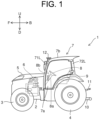
- FIG. 1 is a left side view schematically showing a configuration of a tractor 1, which is an example of a work vehicle of the present embodiment.
- the tractor 1 includes a vehicle body 2.
- a ground work machine (not shown) can be attached to the rear side of the vehicle body 2.
- a cultivator, a plow, or a fertilizer applicator can be used, but it is not limited to this.
- a front part of the vehicle body 2 is supported by a pair of left and right front wheels 3.
- a rear part of the vehicle body 2 is supported by a pair of left and right rear wheels 4.
- a hood 5 is arranged on the front part of the vehicle body 2.
- An engine 6 is arranged below the hood 5 as a drive source.
- the engine 6 is, for example, configured as a diesel engine. However, it is not limited to this, and the engine 6 may, for example, be configured as a gasoline engine. Furthermore, an electric motor may be used as a drive source in addition to the engine 6, or instead of the engine 6.
- An upper part of the vehicle body 2 on the rear of the hood 5 is provided with a cabin 7 for the driver to board.
- the left side of the cabin 7 is provided with a door 7a that pivots to open toward the front. The driver can get in and out of the cabin 7 by opening and closing the door 7a.
- the door 7a may be provided on the right side of the cabin 7, or on both the left and right sides of the cabin 7.
- a steering wheel 8 and the driver's seat 9 are provided inside the cabin 7.
- the driver is capable of determining the advancing direction of the tractor 1 by being seated in the driver's seat 9 and performing steering operations with respect to the steering wheel 8.
- a shaft of the steering wheel 8 is covered by a steering column 8a.
- a display panel is provided inside a dashboard 8b above the steering column 8a. The display panel displays information, warning lights, and the like for each instrument installed on the tractor 1.
- FIG. 2 is a plan view schematically showing a configuration of the inside of the cabin 7 of the tractor 1.
- the roof 7b is supported on the vehicle body 2 by four pillars.
- the four pillars are a right-front pillar 71R, a left-front pillar 71L, a right-rear pillar 72R, and a left-rear pillar 72L.
- the right-front pillar 71R is a first front pillar arranged on the right-front of the driver's seat 9.
- the left-front pillar 71L is a second front pillar arranged on the left-front of the driver's seat 9.
- the right-rear pillar 72R is arranged on the right-rear of the driver's seat 9.
- the left-rear pillar 72L is arranged on the left-rear the driver's seat 9.
- the cabin 7 includes the right-front pillar 71R as the first front pillar and the left-front pillar 71L as the second front pillar, which are arranged further forward than the driver's seat 9, and on one side and another side in the width direction of the driver's seat 9.
- a three-point link mechanism is provided on the rear side of the vehicle body 2.
- the three-point link mechanism includes a pair of left and right lower links 10 and upper links 11.
- the ground work machine mentioned above is configured so as to be attachable to the three-point link mechanism.
- a raising/lowering device (not shown) having a hydraulic system such as a raising/lowering cylinder is provided on the rear side of the vehicle body 2.
- the raising/lowering device is capable of raising and lowering the ground work machine by raising and lowering the three-point link mechanism.
- the tractor 1 further includes an antenna unit 12.
- the antenna unit 12 is a positioning device that includes an inertial measurement unit (IMU), a global navigation satellite system (GNSS) antenna, and the like, and detects the position of the vehicle body 2 based on signals transmitted from positioning satellites (not shown).
- the antenna unit 12 is attached, for example, to the roof 7b of the cabin 7, but may be attached to a position other than the roof 7b.
- the position information of the tractor 1 acquired by the antenna unit 12 is transmitted to an assist monitor device 40 (see FIGS. 5 and 6 ) described later, and is used to generate information that is provided to the driver (such as the straight travel routes of the tractor 1).
- FIG. 3 is a left side view showing enlarged the inside of the cabin 7.
- the tractor 1 of the present embodiment includes a monitoring device 20.
- the monitoring device 20 monitors the driver seated in the driver's seat 9.
- the monitoring device 20 monitors at least one of drowsiness, dozing, inattention, a physical state, and an undrivable state of the driver.
- the monitoring device 20 is attached, for example, to the right-front pillar 71R of the cabin 7.
- the monitoring device 20 As a result of installing the monitoring device 20 in such a position, it is possible to monitor not only the driver's face but also the posture and movements of the upper body (the same applies when the monitoring device 20 is attached to the left-front pillar 71L of the cabin 7).
- the imaging area of the monitoring device 20 is limited to only the driver's face, it is possible to lose sight of the driver. For example, a situation may occur in which the driver's upper body has leaned significantly forward, such that it is not possible for the driver's face to be captured by the monitoring device 20, or the driver's upper body may face the opposite side to the monitoring device 20, such that the driver's face cannot be captured. As a result of setting the driver's upper body as the imaging area of the monitoring device 20, it is possible to monitor the driver without losing sight of the driver.
- the cause (such as the reason being movement of the driver's upper body) can be determined. If the driver's face cannot be captured by the monitoring device 20 due to the situations described above, it is not problematic if this is a temporary situation, but if the situation continues for a threshold period of time or more, it can be determined that an undrivable state has occurred. Note that details of the position of the monitoring device 20 will be described later.
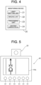
- FIG. 4 is a block diagram schematically showing a configuration of the monitoring device 20.
- the monitoring device 20 includes a light-emitting unit 21, an imaging unit 22, a processing unit 23, and a monitoring communication unit 24.
- the light-emitting unit 21 is a light source that emits light toward a preset eye point EP, and is configured by, for example, a light-emitting diode that emits infrared light.
- the eye point EP is a point corresponding to the position of the eyes of the driver when the driver is seated in the driver's seat 9.
- the eye point EP is preset in accordance with a standard as a position that is a predetermined distance above the driver's seat 9. As a result of the light-emitting unit 21 emitting light toward the eye point EP, it is possible to illuminate the driver's face when the driver is seated in the driver's seat 9.
- the imaging unit 22 is a camera that acquires images by capturing the face of the driver seated in the driver's seat 9.
- the imaging unit 22 is capable of acquiring images of the driver's face by receiving the light that has been emitted from the light-emitting unit 21 and reflected by the driver's face.
- the images acquired by the imaging unit 22 may be still images acquired at predetermined frame intervals, or a video acquired by consecutive capture.
- the processing unit 23 determines the state of the driver by performing predetermined analysis processing with respect to the images acquired by the imaging unit 22. For example, the processing unit 23 acquires, from the images captured by the imaging unit 22, features such as the extent to which the driver's eyes or mouth are open or closed, the opening and closing speed, and the direction of the line of sight, and when a state in which the driver does not appear in the images from the imaging unit 22 (a state in which the driver has not been captured) continues for a predetermined period of time, extracts the period of time that the driver has not been captured, identifies the presence or absence of drowsiness, the presence or absence of dozing, the presence or absence of inattention, and the presence or absence of an undrivable state of the driver from the extracted features, and outputs the result to the outside.
- the undrivable state referred to here not only includes an undrivable state caused by a loss of consciousness or sudden illness of the driver, such as a stroke, but also a state where the driver has fallen off or become separated from the driver's
- the processing unit 23 described above is configured by an arithmetic device specialized for real-time image processing, such as a graphics processing unit (GPU). For example, by training the processing unit 23 in advance using machine learning, it is possible to cause the processing unit 23 to extract and identify features from input images. Furthermore, the processing unit 23 can also recognize the driver's blood flow based on color changes over a predetermined period in specific locations of the image, and acquire heart rate or blood pressure data (vital data). This allows the processing unit 23 to determine whether or not the driver's physical state is satisfactory based on the acquired vital sign data.
- a graphics processing unit GPU
- the processing unit 23 can also recognize the driver's blood flow based on color changes over a predetermined period in specific locations of the image, and acquire heart rate or blood pressure data (vital data). This allows the processing unit 23 to determine whether or not the driver's physical state is satisfactory based on the acquired vital sign data.
- the monitoring communication unit 24 is an interface for performing communication with the outside, and includes a terminal or connector that is connected to a cable.
- the monitoring communication unit 24 may be configured to wirelessly communicate with the outside.
- the monitoring communication unit 24 includes an antenna, a transmitting/receiving circuit, a modulation circuit, a demodulation circuit, and the like.
- the tractor 1 includes a support member 75.
- the support member 75 supports the monitoring device 20.
- the monitoring device 20 is attached to the right-front pillar 71R of the cabin 7 via an attachment member such as a stay.
- the right-front pillar 71R supports the monitoring device 20 via the attachment member.
- the right-front pillar 71R constitutes the support member 75.
- an axis passing through the center W0 of the driver's seat 9 in the width direction and extending along the front-rear direction is defined as a reference axis A1.
- the monitoring device 20 is supported by the right-front pillar 71R, the monitoring device 20 is arranged in a position that further forward than the driver's seat 9, and offset in the width direction of the driver's seat 9 with respect to the reference axis A1.
- an angle ⁇ 1 formed between the reference axis A1 and an axis M1 connecting the monitoring device 20 and the eye point EP in a plan view is set to about 35°. Note that the angle ⁇ 1 is appropriately set in a range of greater than 0° and 50° or less.
- the processing unit 23 when identification (detection) of the state of the driver is performed by extracting features from images captured in a state where the driver's face is facing the side, the extent to which the driver's eyes are open in the images (the area of the eyeballs) differs from that of a front view. Consequently, in reality, even when the driver is not being inattentive or dozing, there may be cases where the driver is erroneously detected as being inattentive or the like. For this reason, as the images used for feature extraction, it is desirable to use images to the extent possible that capture the driver from the direction that the driver's face is facing.
- the monitoring device 20 can capture and monitor the driver from the direction in which the driver's face is facing (from the right-front side of the driver).
- the frequency with which the monitoring device 20 erroneously detects the condition of the driver can be reduced, and the state of the driver can be accurately detected.
- the monitoring device 20 that monitors the driver can be installed in an appropriate position that emphasizes the driver's posture while driving (in particular, the direction of the face, and the posture and movement of the upper body), and the state of the driver seated in the driver's seat 9 can be accurately detected.
- the support member 75 that supports the monitoring device 20 is highly effective for the support member 75 that supports the monitoring device 20 to be constituted by the right-front pillar 71R that is arranged relatively on the right side.
- the position in the up-down direction of the monitoring device 20, which is supported by the support member 75 (right-front pillar 71R), is lower than the eye point EP.
- an angle (angle of depression) ⁇ 2 formed between an axis A2 extending through the eye point EP in the front-rear direction, and an axis M2 connecting the monitoring device 20 and the eye point EP is set to about 30°. Note that the angle ⁇ 2 is appropriately set in a range of greater than 0° and 45° or less.
- the monitoring device 20 may be provided with a structure that enables a user (driver) to adjust the position of the monitoring device 20 such that the monitoring device 20 can be arranged according to the height of the driver in a position that satisfies the angle shown in FIG. 3 .
- an online calibration function that is, a function that performs automatic correction according to the camera position, is used to adjust the sensing function of the camera according to the height of the driver.
- the driver that is driving the tractor 1 sometimes looks at the front wheels 3 (see FIG. 1 ) while performing work, and in this case, the driver's line of sight faces downward.
- the monitoring device 20 monitors the driver from diagonally forward and downward of the driver. In this respect, it is desirable for the monitoring device 20 to be in a position that is lower than the eye point EP as in the present embodiment.
- the tractor 1 of the present embodiment may further include an assist monitor device 40.
- the assist monitor device 40 is a control device that assists the automatic straight travel of the tractor 1.
- FIG. 5 is a front view schematically showing the appearance of the assist monitor device 40.
- FIG. 6 is a block diagram schematically showing a configuration of the assist monitor device 40.
- the monitoring device 20 is integrally provided with the assist monitor device 40.
- the monitoring device 20 is integrally provided in an upper portion of the assist monitor device 40.
- the position of the monitoring device 20 with respect to the assist monitor device 40 is not particularly limited.
- the monitoring device 20 may be integrally provided in a side surface of the assist monitor device 40.
- the monitoring device 20 may be integrally provided with the assist monitor device 40 when the assist monitor device 40 is manufactured and shipped, or may be attached to the assist monitor device 40 after separate shipping of the assist monitor device 40 by using a bracket or the like.
- the monitoring device 20 is integrally provided with the assist monitor device 40 as in the present embodiment.
- the assist monitor device 40 includes an input unit 41, an assist path generation unit 42, an output control unit 43, an information output unit 44, and a control communication unit 45.
- the input unit 41 is an operation unit for the driver to input a start point and an end point of straight travel and the like, and is configured, for example, by push buttons. Note that the input unit 41 may be configured by a touch panel-type input unit.
- the driver causes the tractor 1 to actually travel to the start point of the straight travel, and inputs the start point using the input unit 41. As a result, the position information of the start point is acquired. Next, the driver causes the tractor 1 to actually travel to the end point of the straight travel, and inputs the end point using the input unit 41. As a result, the position information of the end point is acquired.
- the assist path generation unit 42 generates a reference line by connecting the start point and the end point of the straight travel that has been input using the input unit 41 with a straight line. Then, the assist path generation unit 42 generates, as straight routes, lines that are parallel to the reference line with a predetermined spacing (corresponding to the width of the tractor 1).
- the output control unit 43 controls the information output unit 44.
- the information output unit 44 includes a display unit 44a and a sound output unit 44b.
- the display unit 44a is configured, for example, by a liquid crystal display device.
- the sound output unit 44b is configured, for example, by a buzzer.
- the output control unit 43 may also function as a main control unit that controls the operation of each unit of the assist monitor device 40 other than the information output unit 44.
- Such an output control unit 43 is configured by, for example, a central processing unit (CPU).
- An operation program of the output control unit 43 is stored in a storage unit (not shown) of the assist monitor device 40. Note that a configuration is also possible in which the main control unit mentioned above is provided separately to the output control unit 43.
- the output control unit 43 displays the straight routes generated by the assist path generation unit 42 on the display unit 44a. At this time, based on the position information of the tractor 1 detected by the antenna unit 12, the output control unit 43 also displays the current travel position of the tractor 1 performing straight travel on the display unit 44a superimposed on the straight routes. Furthermore, at the time of an abnormality, the output control unit 43 also causes a warning sound to be generated from the sound output unit 44b. For example, when the tractor 1 completes straight travel and needs to turn, and a turning operation is not manually performed, a warning sound is emitted from the sound output unit 44b to alert the driver.
- the control communication unit 45 is an interface for performing communication with the monitoring device 20 and the antenna unit 12, and includes an input/output terminal that is connected with a cable or wiring.
- control communication unit 45 may have a configuration that performs wireless communication with the outside by further including an antenna, a transmitting/receiving circuit, a modulation circuit, a demodulation circuit, and the like.
- the output control unit 43 of the assist monitor device 40 outputs a warning from the information output unit 44 when the monitoring device 20 described above has detected an abnormality of the driver.
- the output control unit 43 causes the display unit 44a to display a warning such as "driver abnormality detected".
- the output control unit 43 may output a warning sound from the sound output unit 44b when the monitoring device 20 detects an abnormality of the driver.
- the monitoring device 20 has detected an abnormality of the driver, by displaying a warning display on the display unit 44a, the information provided to the driver is aggregated and displayed on the display unit 44a of the assist monitor device 40. This increases the convenience for the driver.
- the monitoring device 20 has detected an abnormality of the driver, by outputting a warning sound using the sound output unit 44b of the assist monitor device 40, it is not necessary to separately provide dedicated equipment that outputs a warning sound.
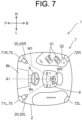
- FIG. 7 is a plan view schematically showing a configuration of a modification of the tractor 1.
- the monitoring device 20 may be supported by each of the right-front pillar 71R and the left-front pillar 71L, and monitor the driver. That is, the monitoring device 20 may be configured to include a right side monitoring device 20R that is supported by the right-front pillar 71R, and a left side monitoring device 20L that is supported by the left-front pillar 71L.
- the right-front pillar 71R and the left-front pillar 71L each constitute the support member 75 that supports the monitoring device 20.
- an abnormality of the driver can be detected based on the monitoring by the right side monitoring device 20R. Furthermore, when the driver performs work by looking toward the left side, an abnormality of the driver can be detected based on the monitoring by the left side monitoring device 20L. That is, regardless of whether the work is performed with the driver's face tilted to the left or right direction, it is possible to accommodate both cases, and the state of the driver can be more accurately detected.
- the monitoring device 20 may be supported by only the left-front pillar 71L, and monitor the driver.
- the left-front pillar 71L constitutes the support member 75 that supports the monitoring device 20.
- an abnormality of the driver can be accurately detected based on the monitoring by the monitoring device 20. Therefore, when the driver performs work while looking toward the left side with a high frequency, a configuration in which only the left-front pillar 71L supports the monitoring device 20 becomes effective.
- the support member 75 that supports the monitoring device 20 may be configured by at least one of the right-front pillar 71R serving as the first front pillar, and the left-front pillar 71L serving as the second front pillar.
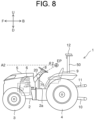
- FIG. 8 is a left side view schematically showing a configuration of another modification of the tractor 1.
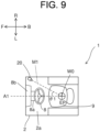
- FIG. 9 is a plan view of the main parts of the tractor 1 in FIG. 8 .
- the tractor 1 shown in FIGS. 8 and 9 does not include the cabin 7 shown in FIG. 1 and the like, and includes a ROPS frame 50.
- the ROPS frame 50 is a guard provided for the purpose of protecting the driver in the event the tractor 1 rolls over, and for example, is provided standing with an inverted letter-U shape on the vehicle body 2 on a rear part of the driver's seat 9.
- the vehicle body 2 is provided with a floor 2a. That is, the tractor 1 includes the floor 2a.
- the floor 2a is positioned on a forward, lower part of the driver's seat 9, and extending in the width direction of the driver's seat 9. The driver is able to get on and off the driver's seat 9 using the floor 2a as a footing.
- the support member 75 may be provided standing on the floor 2a to support the monitoring device 20.
- the position in the left-right direction and the position in the up-down direction of the monitoring device 20 at this time may be set in the ranges of the same angles ⁇ 1 and ⁇ 2 as in the tractor 1 shown in FIGS. 2 and 3 .
- the support member 75 is constituted by, for example, a support pillar, and supports the monitoring device 20 via a mounting jig (not shown).
- the mounting jig may be the same member as the attachment member described above that is used in the type including the cabin, or may be a different member.
- the monitoring device 20 is supported by the support member 75 in the position described above.
- the tractor 1 travels in accordance with the driving performed by a driver.
- a configuration is possible in which autonomous travel is performed based on instructions from a wireless communication terminal.
- the monitoring device 20 is installed in the tractor 1 in the present embodiment.
- an agricultural machine other than the tractor 1 such as a combine harvester or a rice transplanter
- monitor the state of the driver It is also possible to install the monitoring device 20 in the same position as the present embodiment in a construction machine such as a hydraulic excavator (including a backhoe) or a wheel loader, and monitor the state of the driver.
- the position in the up-down direction of the monitoring device 20 may be a higher position than the eye point EP.
- the position in the left-right direction of the monitoring device 20 is a position that is offset in the left-right direction from the front of the driver.
- the direction of the line of sight of the driver may be diagonally upward with respect to the forward direction of the driver.
- a configuration in which the monitoring device 20 is installed in a position higher than the eye point EP is effective from the viewpoint of accurately detecting an abnormality of the driver based on monitoring by the monitoring device 20.
- the work vehicle such as the tractor 1 described in the present embodiment can also be represented by a work vehicle described in the following supplementary notes.
- a work vehicle according to supplementary note (1) comprises:
- a work vehicle according to supplementary note (2) is the work vehicle according to supplementary note (1), further comprising
- a work vehicle according supplementary note (3) is the work vehicle according to supplementary note (2) wherein
- a work vehicle according to supplementary note (4) is the work vehicle according to supplementary note (1), further comprising
- a work vehicle according to supplementary note (5) is the work vehicle according to any one of supplementary notes (1) to (4), wherein the monitoring device monitors for least one of drowsiness, dozing, inattention, a physical state, and an undrivable state of the driver.
- a work vehicle according to supplementary note (6) is the work vehicle according to any one of supplementary notes (1) to (5), further comprising
- a work vehicle according to supplementary note (7) is the work vehicle according to supplementary note (6), wherein
- a work vehicle according to supplementary note (8) is the work vehicle according to supplementary note (7), wherein
- a work vehicle according to supplementary note (9) is the work vehicle according to supplementary note (7) or (8) wherein
- a work vehicle according to supplementary note (10) is the work vehicle according to any one of supplementary notes (1) or (9) wherein a position in up-down direction of the monitoring device that is supported by the support member is lower than an eye point corresponding to a position of an eye of the driver seated in the driver's seat.
- the present invention can be used in work vehicles such as agricultural machines and construction machines.
Landscapes
- Engineering & Computer Science (AREA)
- Mechanical Engineering (AREA)
- Automation & Control Theory (AREA)
- Transportation (AREA)
- Physics & Mathematics (AREA)
- Mathematical Physics (AREA)
- Human Computer Interaction (AREA)
- Mining & Mineral Resources (AREA)
- Civil Engineering (AREA)
- General Engineering & Computer Science (AREA)
- Structural Engineering (AREA)
- Combustion & Propulsion (AREA)
- Chemical & Material Sciences (AREA)
- General Physics & Mathematics (AREA)
- Multimedia (AREA)
- Theoretical Computer Science (AREA)
- Component Parts Of Construction Machinery (AREA)
- Traffic Control Systems (AREA)
Abstract
[Problem] Provided is a work vehicle in which a device that monitors a driver is installed in a suitable position, and that can accurately detect a state of a driver seated in the driver's seat.
[Solution] The work vehicle includes a monitoring device that monitors the driver seated in the driver's seat, and a support member that supports the monitoring device. In a plan view, the direction perpendicular to a width direction of the driver's seat is a front-rear direction, and the side the driver faces in the front-rear direction when seated in the driver's seat is the front side. The monitoring device is arranged in a position further forward than the driver's seat, and is offset in the width direction of the driver's seat with respect to a reference axis along the front-rear direction that passes through the center of the driver's seat in the width direction. The monitoring device is supported by the support member.
Description
- The present invention relates to a work vehicle.
- For example, proposed in
Patent Document 1 is a driver monitor device that captures the face of a driver of a vehicle such as a passenger car with a camera, and then uses image analysis to accurately identify inattention of the driver and issue a warning. The camera is installed on a steering column of the vehicle. - Patent Document 1:
Japanese Unexamined Patent Application Publication No. 2013-152700 - When driving a vehicle such as a passenger car, it is important to pay attention to what is in front of the vehicle. Therefore, the frequency with which a driver's line of sight is tilted in a left-right direction while driving is relatively low. Furthermore, even if a driver's the line of sight is significantly tilted in the left-right direction while driving in order to pay attention to a wider area, this is only momentary. Therefore, if the vehicle being driven is a passenger car, as described in
Patent Document 1, by placing a camera on a steering column located in front of the driver, inattention of the driver can be accurately detected by the camera. - In contrast, in the case of a work vehicle such as a tractor, the driver of the work vehicle often proceeds with the work performed by the work vehicle while looking at the front wheels. In this case, the direction of the driver's line of sight is diagonally downward with respect to the front (forward) direction of the driver. In addition, in a work vehicle such as a hydraulic excavator, depending on the work location, excavation work may be performed, for example, by swinging a boom in a left-right direction while rotating an arm in an up-down direction. At this time, the direction of the driver's line of sight may sometimes be oriented diagonally upward with respect to the front direction of the driver.
- Therefore, in a work vehicle in which the line of sight is often significantly tilted in the left-right direction while working, if inattention is detected by placing a camera in front of the driver, even if the line of sight movements while working do not actually correspond to inattention, the line of sight movements may sometimes be erroneously detected as corresponding to inattention. Therefore, measures to prevent erroneous detection are necessary.
- The present invention has been made in order to solve the problem described above. An object of the present invention is to provide a work vehicle in which a device that monitors a driver is installed in a suitable position, and that can accurately detect a state of the driver seated in the driver's seat.
- A work vehicle according to an aspect of the present invention includes: a monitoring device that monitors a driver that is seated in a driver's seat; and a support member that supports the monitoring device; wherein in a plan view, when a direction perpendicular to a width direction of the driver's seat is a front-rear direction, and a side the driver faces in the front-rear direction when seated in the driver's seat is a front side, the monitoring device is arranged in a position further forward than the driver's seat, and is offset in the width direction of the driver's seat with respect to a reference axis along the front-rear direction that passes through a center of the driver's seat in the width direction, and is supported by the support member.
- According to the configuration described above, it is possible to install a device that monitors a driver in a suitable position, and to accurately detect a state of the driver seated in the driver's seat.
-
-
FIG. 1 is a left side view schematically showing a configuration of a tractor, which is an example of a work vehicle according to an embodiment of the present invention. -
FIG. 2 is a plan view schematically showing a configuration of the inside of a cabin of the tractor. -
FIG. 3 is a left side view showing enlarged the inside of the cabin. -
FIG. 4 is a block diagram schematically showing a configuration of a monitoring device provided in the tractor. -
FIG. 5 is a front view schematically showing the appearance of an assist monitor device provided in the tractor. -
FIG. 6 is a block diagram schematically showing a configuration of the assist monitor device. -
FIG. 7 is a plan view schematically showing a configuration of a modification of the tractor. -
FIG. 8 is a left side view schematically showing a configuration of another modification of the tractor. -
FIG. 9 is a plan view showing a configuration of the main parts of the tractor inFIG. 8 . - An embodiment of the present invention will be described below with reference to the drawings.
- The embodiment of the present invention will be described below with reference to the drawings. In the present embodiment, a tractor will be described as an example of a work vehicle. However, in addition to a tractor, examples of the work vehicle include riding work vehicles such as a rice planter, a combine harvester, a civil engineering and construction work device (such as a hydraulic excavator), and a snowplow.
- In addition, in the present specification, the directions are defined as follows. First, the width direction of a driver's seat 9 (see
FIG. 1 ) of atractor 1 serving as a work vehicle is defined as a left-right direction. Further, in a plan view, a direction perpendicular to the width direction of the driver'sseat 9 is defined as a front-rear direction. In the front-rear direction, the side the driver seated in the driver'sseat 9 faces (the front side) is defined as the "front". The opposite side, that is, the back side of the driver seated in the driver'sseat 9 is defined as the "rear". In addition, the right side with respect to the forward direction of the driver seated in the driver'sseat 9 is defined as the "right", and the left side is defined as the "left". The right side mentioned above is also one side in the width direction. The left side mentioned above is also another side in the width direction. Also, a gravity direction perpendicular to the front-rear direction and the left-right direction is defined as an up-down direction. The upstream side in the gravity direction is defined as "up", and the downstream side is defined as "down". In the drawings, the symbols of "F" for forward, "B" for back, "R" for right, "L" for left, "U" for up, and "D" for down will be shown as necessary. - The above definitions of the directions also apply to other work vehicles. For example, in a hydraulic excavator, because an upper rotating body rotates relative to a lower traveling body, the front-rear direction of the driver's seat provided on the upper rotating body may deviate from the direction in which the hydraulic excavator moves forward and backward. However, by defining the above directions based on the driver's seat, the arrangement and positional relationships of each member in the hydraulic excavator can be considered in the same way as in the present embodiment.
-
FIG. 1 is a left side view schematically showing a configuration of atractor 1, which is an example of a work vehicle of the present embodiment. Thetractor 1 includes avehicle body 2. A ground work machine (not shown) can be attached to the rear side of thevehicle body 2. As the ground work machine, for example, a cultivator, a plow, or a fertilizer applicator can be used, but it is not limited to this. - A front part of the
vehicle body 2 is supported by a pair of left and rightfront wheels 3. A rear part of thevehicle body 2 is supported by a pair of left and rightrear wheels 4. Ahood 5 is arranged on the front part of thevehicle body 2. Anengine 6 is arranged below thehood 5 as a drive source. Theengine 6 is, for example, configured as a diesel engine. However, it is not limited to this, and theengine 6 may, for example, be configured as a gasoline engine. Furthermore, an electric motor may be used as a drive source in addition to theengine 6, or instead of theengine 6. - An upper part of the
vehicle body 2 on the rear of thehood 5 is provided with acabin 7 for the driver to board. The left side of thecabin 7 is provided with adoor 7a that pivots to open toward the front. The driver can get in and out of thecabin 7 by opening and closing thedoor 7a. Thedoor 7a may be provided on the right side of thecabin 7, or on both the left and right sides of thecabin 7. - A
steering wheel 8 and the driver'sseat 9 are provided inside thecabin 7. The driver is capable of determining the advancing direction of thetractor 1 by being seated in the driver'sseat 9 and performing steering operations with respect to thesteering wheel 8. A shaft of thesteering wheel 8 is covered by asteering column 8a. A display panel is provided inside adashboard 8b above thesteering column 8a. The display panel displays information, warning lights, and the like for each instrument installed on thetractor 1. - The
cabin 7 described above is provided with aroof 7b. Theroof 7b is located above the driver'sseat 9 and covers the driver'sseat 9. That is, thetractor 1 is provided with acabin 7 that covers the driver'sseat 9.FIG. 2 is a plan view schematically showing a configuration of the inside of thecabin 7 of thetractor 1. Theroof 7b is supported on thevehicle body 2 by four pillars. The four pillars are a right-front pillar 71R, a left-front pillar 71L, a right-rear pillar 72R, and a left-rear pillar 72L. The right-front pillar 71R is a first front pillar arranged on the right-front of the driver'sseat 9. The left-front pillar 71L is a second front pillar arranged on the left-front of the driver'sseat 9. The right-rear pillar 72R is arranged on the right-rear of the driver'sseat 9. The left-rear pillar 72L is arranged on the left-rear the driver'sseat 9. In this way, thecabin 7 includes the right-front pillar 71R as the first front pillar and the left-front pillar 71L as the second front pillar, which are arranged further forward than the driver'sseat 9, and on one side and another side in the width direction of the driver'sseat 9. - A three-point link mechanism is provided on the rear side of the
vehicle body 2. The three-point link mechanism includes a pair of left and rightlower links 10 andupper links 11. The ground work machine mentioned above is configured so as to be attachable to the three-point link mechanism. Furthermore, a raising/lowering device (not shown) having a hydraulic system such as a raising/lowering cylinder is provided on the rear side of thevehicle body 2. The raising/lowering device is capable of raising and lowering the ground work machine by raising and lowering the three-point link mechanism. - The
tractor 1 further includes anantenna unit 12. Theantenna unit 12 is a positioning device that includes an inertial measurement unit (IMU), a global navigation satellite system (GNSS) antenna, and the like, and detects the position of thevehicle body 2 based on signals transmitted from positioning satellites (not shown). Theantenna unit 12 is attached, for example, to theroof 7b of thecabin 7, but may be attached to a position other than theroof 7b. The position information of thetractor 1 acquired by theantenna unit 12 is transmitted to an assist monitor device 40 (seeFIGS. 5 and6 ) described later, and is used to generate information that is provided to the driver (such as the straight travel routes of the tractor 1). -
FIG. 3 is a left side view showing enlarged the inside of thecabin 7. As shown inFIGS. 2 and3 , thetractor 1 of the present embodiment includes amonitoring device 20. Themonitoring device 20 monitors the driver seated in the driver'sseat 9. In the present embodiment, in order to prevent accidents during operation of thetractor 1, themonitoring device 20 monitors at least one of drowsiness, dozing, inattention, a physical state, and an undrivable state of the driver. Themonitoring device 20 is attached, for example, to the right-front pillar 71R of thecabin 7. As a result of installing themonitoring device 20 in such a position, it is possible to monitor not only the driver's face but also the posture and movements of the upper body (the same applies when themonitoring device 20 is attached to the left-front pillar 71L of the cabin 7). - Here, because the driver of the work vehicle (here, the tractor 1) makes large movements, if the imaging area of the
monitoring device 20 is limited to only the driver's face, it is possible to lose sight of the driver. For example, a situation may occur in which the driver's upper body has leaned significantly forward, such that it is not possible for the driver's face to be captured by themonitoring device 20, or the driver's upper body may face the opposite side to themonitoring device 20, such that the driver's face cannot be captured. As a result of setting the driver's upper body as the imaging area of themonitoring device 20, it is possible to monitor the driver without losing sight of the driver. Furthermore, even when themonitoring device 20 loses sight of the driver's face, the cause (such as the reason being movement of the driver's upper body) can be determined. If the driver's face cannot be captured by themonitoring device 20 due to the situations described above, it is not problematic if this is a temporary situation, but if the situation continues for a threshold period of time or more, it can be determined that an undrivable state has occurred. Note that details of the position of themonitoring device 20 will be described later. -
FIG. 4 is a block diagram schematically showing a configuration of themonitoring device 20. Themonitoring device 20 includes a light-emittingunit 21, animaging unit 22, aprocessing unit 23, and amonitoring communication unit 24. The light-emittingunit 21 is a light source that emits light toward a preset eye point EP, and is configured by, for example, a light-emitting diode that emits infrared light. Here, the eye point EP is a point corresponding to the position of the eyes of the driver when the driver is seated in the driver'sseat 9. The eye point EP is preset in accordance with a standard as a position that is a predetermined distance above the driver'sseat 9. As a result of the light-emittingunit 21 emitting light toward the eye point EP, it is possible to illuminate the driver's face when the driver is seated in the driver'sseat 9. - The
imaging unit 22 is a camera that acquires images by capturing the face of the driver seated in the driver'sseat 9. For example, theimaging unit 22 is capable of acquiring images of the driver's face by receiving the light that has been emitted from the light-emittingunit 21 and reflected by the driver's face. The images acquired by theimaging unit 22 may be still images acquired at predetermined frame intervals, or a video acquired by consecutive capture. - The
processing unit 23 determines the state of the driver by performing predetermined analysis processing with respect to the images acquired by theimaging unit 22. For example, theprocessing unit 23 acquires, from the images captured by theimaging unit 22, features such as the extent to which the driver's eyes or mouth are open or closed, the opening and closing speed, and the direction of the line of sight, and when a state in which the driver does not appear in the images from the imaging unit 22 (a state in which the driver has not been captured) continues for a predetermined period of time, extracts the period of time that the driver has not been captured, identifies the presence or absence of drowsiness, the presence or absence of dozing, the presence or absence of inattention, and the presence or absence of an undrivable state of the driver from the extracted features, and outputs the result to the outside. Note that the undrivable state referred to here not only includes an undrivable state caused by a loss of consciousness or sudden illness of the driver, such as a stroke, but also a state where the driver has fallen off or become separated from the driver'sseat 9. - The
processing unit 23 described above is configured by an arithmetic device specialized for real-time image processing, such as a graphics processing unit (GPU). For example, by training theprocessing unit 23 in advance using machine learning, it is possible to cause theprocessing unit 23 to extract and identify features from input images. Furthermore, theprocessing unit 23 can also recognize the driver's blood flow based on color changes over a predetermined period in specific locations of the image, and acquire heart rate or blood pressure data (vital data). This allows theprocessing unit 23 to determine whether or not the driver's physical state is satisfactory based on the acquired vital sign data. - The
monitoring communication unit 24 is an interface for performing communication with the outside, and includes a terminal or connector that is connected to a cable. Themonitoring communication unit 24 may be configured to wirelessly communicate with the outside. In this case, themonitoring communication unit 24 includes an antenna, a transmitting/receiving circuit, a modulation circuit, a demodulation circuit, and the like. - Next, details of the position of the
monitoring device 20 will be described. As shown inFIG. 2 , thetractor 1 includes asupport member 75. Thesupport member 75 supports themonitoring device 20. For example, themonitoring device 20 is attached to the right-front pillar 71R of thecabin 7 via an attachment member such as a stay. In other words, the right-front pillar 71R supports themonitoring device 20 via the attachment member. - Therefore, in this case, the right-
front pillar 71R constitutes thesupport member 75. - Here, in
FIG. 2 , an axis passing through the center W0 of the driver'sseat 9 in the width direction and extending along the front-rear direction is defined as a reference axis A1. In the present embodiment, because themonitoring device 20 is supported by the right-front pillar 71R, themonitoring device 20 is arranged in a position that further forward than the driver'sseat 9, and offset in the width direction of the driver'sseat 9 with respect to the reference axis A1. In the present embodiment, an angle θ1 formed between the reference axis A1 and an axis M1 connecting themonitoring device 20 and the eye point EP in a plan view is set to about 35°. Note that the angle θ1 is appropriately set in a range of greater than 0° and 50° or less. - For example, in the monitoring device 20 (in particular, the processing unit 23), when identification (detection) of the state of the driver is performed by extracting features from images captured in a state where the driver's face is facing the side, the extent to which the driver's eyes are open in the images (the area of the eyeballs) differs from that of a front view. Consequently, in reality, even when the driver is not being inattentive or dozing, there may be cases where the driver is erroneously detected as being inattentive or the like. For this reason, as the images used for feature extraction, it is desirable to use images to the extent possible that capture the driver from the direction that the driver's face is facing.
- As a result of arranging the
monitoring device 20 as shown inFIG. 2 , even if the driver seated in the driver'sseat 9 often looks to the right while working, themonitoring device 20 can capture and monitor the driver from the direction in which the driver's face is facing (from the right-front side of the driver). As a result, the frequency with which themonitoring device 20 erroneously detects the condition of the driver (the presence or absence of inattention, the presence or absence of drowsiness, the presence or absence of dozing, a physical state, or the presence or absence of an undrivable state) can be reduced, and the state of the driver can be accurately detected. That is, themonitoring device 20 that monitors the driver can be installed in an appropriate position that emphasizes the driver's posture while driving (in particular, the direction of the face, and the posture and movement of the upper body), and the state of the driver seated in the driver'sseat 9 can be accurately detected. - In addition, in the
tractor 1, with the exception of some levers, it is frequently the case that various operation levers 31,operation buttons 32, and the like, are arranged together as shown inFIG. 2 . In this case, the driver will often tilt the face to the right side in order to operate the operation levers 31 and the like. Therefore, in thetractor 1, in order to accurately monitor the state of the driver with themonitoring device 20, it is desirable for themonitoring device 20 to monitor the driver from the right-front side. In this respect, as described in the present embodiment, among the right-front pillar 71R serving as the first front pillar, and the left-front pillar 71L serving as the second front pillar, it is highly effective for thesupport member 75 that supports themonitoring device 20 to be constituted by the right-front pillar 71R that is arranged relatively on the right side. - Furthermore, in the present embodiment, as shown in
FIG. 3 , the position in the up-down direction of themonitoring device 20, which is supported by the support member 75 (right-front pillar 71R), is lower than the eye point EP. In the present embodiment, in a side view, an angle (angle of depression) θ2 formed between an axis A2 extending through the eye point EP in the front-rear direction, and an axis M2 connecting themonitoring device 20 and the eye point EP is set to about 30°. Note that the angle θ2 is appropriately set in a range of greater than 0° and 45° or less. - The
monitoring device 20 may be provided with a structure that enables a user (driver) to adjust the position of themonitoring device 20 such that themonitoring device 20 can be arranged according to the height of the driver in a position that satisfies the angle shown inFIG. 3 . In this case, an online calibration function, that is, a function that performs automatic correction according to the camera position, is used to adjust the sensing function of the camera according to the height of the driver. - The driver that is driving the
tractor 1 sometimes looks at the front wheels 3 (seeFIG. 1 ) while performing work, and in this case, the driver's line of sight faces downward. In order to accurately monitor the state of the driver when the driver is facing downward, it is desirable that themonitoring device 20 monitors the driver from diagonally forward and downward of the driver. In this respect, it is desirable for themonitoring device 20 to be in a position that is lower than the eye point EP as in the present embodiment. - The
tractor 1 of the present embodiment may further include anassist monitor device 40. Theassist monitor device 40 is a control device that assists the automatic straight travel of thetractor 1.FIG. 5 is a front view schematically showing the appearance of theassist monitor device 40.FIG. 6 is a block diagram schematically showing a configuration of theassist monitor device 40. - The
monitoring device 20 is integrally provided with theassist monitor device 40. In the present embodiment, themonitoring device 20 is integrally provided in an upper portion of theassist monitor device 40. However, the position of themonitoring device 20 with respect to theassist monitor device 40 is not particularly limited. For example, themonitoring device 20 may be integrally provided in a side surface of theassist monitor device 40. Furthermore, themonitoring device 20 may be integrally provided with theassist monitor device 40 when theassist monitor device 40 is manufactured and shipped, or may be attached to theassist monitor device 40 after separate shipping of theassist monitor device 40 by using a bracket or the like. - From the perspective of arranging the
monitoring device 20 and theassist monitor device 40 together in a compact manner, it is preferable that themonitoring device 20 is integrally provided with theassist monitor device 40 as in the present embodiment. - As shown in
FIGS. 5 and6 , theassist monitor device 40 includes aninput unit 41, an assistpath generation unit 42, anoutput control unit 43, an information output unit 44, and acontrol communication unit 45. - The
input unit 41 is an operation unit for the driver to input a start point and an end point of straight travel and the like, and is configured, for example, by push buttons. Note that theinput unit 41 may be configured by a touch panel-type input unit. - When a travel mode that assists straight travel is used, the driver causes the
tractor 1 to actually travel to the start point of the straight travel, and inputs the start point using theinput unit 41. As a result, the position information of the start point is acquired. Next, the driver causes thetractor 1 to actually travel to the end point of the straight travel, and inputs the end point using theinput unit 41. As a result, the position information of the end point is acquired. - The assist
path generation unit 42 generates a reference line by connecting the start point and the end point of the straight travel that has been input using theinput unit 41 with a straight line. Then, the assistpath generation unit 42 generates, as straight routes, lines that are parallel to the reference line with a predetermined spacing (corresponding to the width of the tractor 1). - The
output control unit 43 controls the information output unit 44. The information output unit 44 includes adisplay unit 44a and asound output unit 44b. Thedisplay unit 44a is configured, for example, by a liquid crystal display device. Thesound output unit 44b is configured, for example, by a buzzer. Note that theoutput control unit 43 may also function as a main control unit that controls the operation of each unit of theassist monitor device 40 other than the information output unit 44. Such anoutput control unit 43 is configured by, for example, a central processing unit (CPU). An operation program of theoutput control unit 43 is stored in a storage unit (not shown) of theassist monitor device 40. Note that a configuration is also possible in which the main control unit mentioned above is provided separately to theoutput control unit 43. - The
output control unit 43 displays the straight routes generated by the assistpath generation unit 42 on thedisplay unit 44a. At this time, based on the position information of thetractor 1 detected by theantenna unit 12, theoutput control unit 43 also displays the current travel position of thetractor 1 performing straight travel on thedisplay unit 44a superimposed on the straight routes. Furthermore, at the time of an abnormality, theoutput control unit 43 also causes a warning sound to be generated from thesound output unit 44b. For example, when thetractor 1 completes straight travel and needs to turn, and a turning operation is not manually performed, a warning sound is emitted from thesound output unit 44b to alert the driver. - The
control communication unit 45 is an interface for performing communication with themonitoring device 20 and theantenna unit 12, and includes an input/output terminal that is connected with a cable or wiring. - Note that the
control communication unit 45 may have a configuration that performs wireless communication with the outside by further including an antenna, a transmitting/receiving circuit, a modulation circuit, a demodulation circuit, and the like. - In the present embodiment, the
output control unit 43 of theassist monitor device 40 outputs a warning from the information output unit 44 when themonitoring device 20 described above has detected an abnormality of the driver. For example, when themonitoring device 20 has detected an abnormality (for example, dozing) of the driver, theoutput control unit 43 causes thedisplay unit 44a to display a warning such as "driver abnormality detected". Furthermore, for example, theoutput control unit 43 may output a warning sound from thesound output unit 44b when themonitoring device 20 detects an abnormality of the driver. - In this way, when the
monitoring device 20 has detected an abnormality of the driver, by using the information output unit 44 of theassist monitor device 40 as a member that produces a warning, it is not necessary to provide dedicated equipment that outputs a warning separately to the information output unit 44. - Also, when the
monitoring device 20 has detected an abnormality of the driver, by displaying a warning display on thedisplay unit 44a, the information provided to the driver is aggregated and displayed on thedisplay unit 44a of theassist monitor device 40. This increases the convenience for the driver. - In addition, when the
monitoring device 20 has detected an abnormality of the driver, by outputting a warning sound using thesound output unit 44b of theassist monitor device 40, it is not necessary to separately provide dedicated equipment that outputs a warning sound. -
FIG. 7 is a plan view schematically showing a configuration of a modification of thetractor 1. As shown in the drawing, themonitoring device 20 may be supported by each of the right-front pillar 71R and the left-front pillar 71L, and monitor the driver. That is, themonitoring device 20 may be configured to include a right side monitoring device 20R that is supported by the right-front pillar 71R, and a left side monitoring device 20L that is supported by the left-front pillar 71L. In this case, the right-front pillar 71R and the left-front pillar 71L each constitute thesupport member 75 that supports themonitoring device 20. - In the configuration of
FIG. 7 , when the driver performs work by looking toward the right side, an abnormality of the driver can be detected based on the monitoring by the right side monitoring device 20R. Furthermore, when the driver performs work by looking toward the left side, an abnormality of the driver can be detected based on the monitoring by the left side monitoring device 20L. That is, regardless of whether the work is performed with the driver's face tilted to the left or right direction, it is possible to accommodate both cases, and the state of the driver can be more accurately detected. - Although not illustrated, the
monitoring device 20 may be supported by only the left-front pillar 71L, and monitor the driver. In this case, the left-front pillar 71L constitutes thesupport member 75 that supports themonitoring device 20. In such a configuration, when the driver performs work by looking toward the left side with a high frequency, an abnormality of the driver can be accurately detected based on the monitoring by themonitoring device 20. Therefore, when the driver performs work while looking toward the left side with a high frequency, a configuration in which only the left-front pillar 71L supports themonitoring device 20 becomes effective. - From the above description, in the present embodiment, it can be said that the
support member 75 that supports themonitoring device 20 may be configured by at least one of the right-front pillar 71R serving as the first front pillar, and the left-front pillar 71L serving as the second front pillar. -
FIG. 8 is a left side view schematically showing a configuration of another modification of thetractor 1.FIG. 9 is a plan view of the main parts of thetractor 1 inFIG. 8 . Thetractor 1 shown inFIGS. 8 and9 does not include thecabin 7 shown inFIG. 1 and the like, and includes aROPS frame 50. TheROPS frame 50 is a guard provided for the purpose of protecting the driver in the event thetractor 1 rolls over, and for example, is provided standing with an inverted letter-U shape on thevehicle body 2 on a rear part of the driver'sseat 9. - The
vehicle body 2 is provided with afloor 2a. That is, thetractor 1 includes thefloor 2a. Thefloor 2a is positioned on a forward, lower part of the driver'sseat 9, and extending in the width direction of the driver'sseat 9. The driver is able to get on and off the driver'sseat 9 using thefloor 2a as a footing. - In this way, when the
tractor 1 is a type that does not include the cabin 7 (non-cabin specification), thesupport member 75 may be provided standing on thefloor 2a to support themonitoring device 20. The position in the left-right direction and the position in the up-down direction of themonitoring device 20 at this time may be set in the ranges of the same angles θ1 and θ2 as in thetractor 1 shown inFIGS. 2 and3 . Thesupport member 75 is constituted by, for example, a support pillar, and supports themonitoring device 20 via a mounting jig (not shown). The mounting jig may be the same member as the attachment member described above that is used in the type including the cabin, or may be a different member. - Even in the case of the
tractor 1 having a non-cabin specification, from the viewpoint of accurately monitoring the state of the driver, as shown inFIG. 8 , it is desirable that themonitoring device 20 is supported by thesupport member 75 in the position described above. - In the present embodiment, the
tractor 1 travels in accordance with the driving performed by a driver. However, a configuration is possible in which autonomous travel is performed based on instructions from a wireless communication terminal. - In the present embodiment, a case where the
monitoring device 20 is installed in thetractor 1 has been described. However, it is also possible to install themonitoring device 20 in the same position as the present embodiment in an agricultural machine other than thetractor 1, such as a combine harvester or a rice transplanter, and monitor the state of the driver. It is also possible to install themonitoring device 20 in the same position as the present embodiment in a construction machine such as a hydraulic excavator (including a backhoe) or a wheel loader, and monitor the state of the driver. - In particular, when the
monitoring device 20 is installed in a hydraulic excavator, the position in the up-down direction of themonitoring device 20 may be a higher position than the eye point EP. The position in the left-right direction of themonitoring device 20 is a position that is offset in the left-right direction from the front of the driver. When performing work with a hydraulic excavator, depending on the work location, the direction of the line of sight of the driver may be diagonally upward with respect to the forward direction of the driver. In cases where the driver frequently performs work while looking diagonally upward, a configuration in which themonitoring device 20 is installed in a position higher than the eye point EP is effective from the viewpoint of accurately detecting an abnormality of the driver based on monitoring by themonitoring device 20. - The work vehicle such as the
tractor 1 described in the present embodiment can also be represented by a work vehicle described in the following supplementary notes. - A work vehicle according to supplementary note (1) comprises:
- a monitoring device that monitors a driver that is seated in a driver's seat; and
- a support member that supports the monitoring device; wherein
- in a plan view, when a direction perpendicular to a width direction of the driver's seat is a front-rear direction, and a side the driver faces in the front-rear direction when seated in the driver's seat is a front side,
- the monitoring device is arranged in a position further forward than the driver's seat, and is offset in the width direction of the driver's seat with respect to a reference axis along the front-rear direction that passes through a center of the driver's seat in the width direction, and is supported by the support member.
- A work vehicle according to supplementary note (2) is the work vehicle according to supplementary note (1), further comprising
- a cabin that covers the driver's seat, wherein
- the cabin is further forward than the driver's seat, and has a first front pillar and a second front pillar that are arranged on one side and another side in the width direction of the driver's seat, and
- the support member is constituted by at least one of the first front pillar and the second front pillar.
- A work vehicle according supplementary note (3) is the work vehicle according to supplementary note (2) wherein
- when the one side in the width direction of the driver's seat is a right side, and the another side is a left side,
- the support member is constituted by a pillar that is arranged relatively on the right side among the first front pillar and the second front pillar.
- A work vehicle according to supplementary note (4) is the work vehicle according to supplementary note (1), further comprising
- a floor positioned on a forward, lower portion of the driver's seat, and extending in the width direction of the driver's seat, wherein
- the support member is provided standing on the floor, and supports the monitoring device.
- A work vehicle according to supplementary note (5) is the work vehicle according to any one of supplementary notes (1) to (4), wherein
the monitoring device monitors for least one of drowsiness, dozing, inattention, a physical state, and an undrivable state of the driver. - A work vehicle according to supplementary note (6) is the work vehicle according to any one of supplementary notes (1) to (5), further comprising
- an assist monitor device that assists automatic straight travel, wherein
- the monitoring device is integrally provided with the assist monitor device.
- A work vehicle according to supplementary note (7) is the work vehicle according to supplementary note (6), wherein
- the assist monitor device is provided with an information output unit and an output control unit, and
- the output control unit outputs a warning from the information output unit when the monitoring device detects an abnormality of the driver.
- A work vehicle according to supplementary note (8) is the work vehicle according to supplementary note (7), wherein
- the information output unit includes a display unit, and
- the output control unit outputs a warning on the display unit when the monitoring device detects an abnormality of the driver.
- A work vehicle according to supplementary note (9) is the work vehicle according to supplementary note (7) or (8) wherein
- the information output unit includes a sound output unit, and
- the output control unit outputs a warning sound from the sound output unit when the monitoring device detects an abnormality of the driver.
- A work vehicle according to supplementary note (10) is the work vehicle according to any one of supplementary notes (1) or (9) wherein
a position in up-down direction of the monitoring device that is supported by the support member is lower than an eye point corresponding to a position of an eye of the driver seated in the driver's seat. - Although an embodiment of the present invention has been described above, the scope of the present invention is not limited to the embodiment. The present invention can be implemented by being expanded or changed within a scope not departing from the gist of the invention.
- The present invention can be used in work vehicles such as agricultural machines and construction machines.
-
- 1 Tractor (work vehicle)
- 2a Floor
- 7 Cabin
- 9 Driver's seat
- 20 Monitoring device
- 20L Left side monitoring device
- 20R Right side monitoring device
- 40 Assist monitor device
- 43 Output control unit
- 44 Information output unit
- 44a Display unit
- 44b Sound output unit
- 71L Left-front pillar (second front pillar, support member)
- 71R Right-front pillar (first front pillar, support member)
- 75 Support member
- A1 Reference axis
- EP Eye point
- W0 Center
Claims (10)
- A work vehicle comprising:a monitoring device that monitors a driver that is seated in a driver's seat; anda support member that supports the monitoring device; whereinin a plan view, when a direction perpendicular to a width direction of the driver's seat is a front-rear direction, and a side the driver faces in the front-rear direction when seated in the driver's seat is a front side,the monitoring device is arranged in a position further forward than the driver's seat, and is offset in the width direction of the driver's seat with respect to a reference axis along the front-rear direction that passes through a center of the driver's seat in the width direction, and is supported by the support member.
- The work vehicle according to claim 1, further comprisinga cabin that covers the driver's seat, whereinthe cabin is further forward than the driver's seat, and has a first front pillar and a second front pillar that are arranged on one side and another side in the width direction of the driver's seat, andthe support member is constituted by at least one of the first front pillar and the second front pillar.
- The work vehicle according to claim 2, whereinwhen the one side in the width direction of the driver's seat is a right side, and the another side is a left side,the support member is constituted by a pillar that is arranged relatively on the right side among the first front pillar and the second front pillar.
- The work vehicle according to claim 1, further comprisinga floor positioned on a forward, lower portion of the driver's seat, and extending in the width direction of the driver's seat, whereinthe support member is provided standing on the floor, and supports the monitoring device.
- The work vehicle according to claim 1, wherein
the monitoring device monitors for least one of drowsiness, dozing, inattention, a physical state, and an undrivable state of the driver. - The work vehicle according to claim 1, further comprisingan assist monitor device that assists automatic straight travel, whereinthe monitoring device is integrally provided with the assist monitor device.
- The work vehicle according to claim 6, whereinthe assist monitor device is provided with an information output unit and an output control unit, andthe output control unit outputs a warning from the information output unit when the monitoring device detects an abnormality of the driver.
- The work vehicle according to claim 7, whereinthe information output unit includes a display unit, andthe output control unit outputs a warning on the display unit when the monitoring device detects an abnormality of the driver.
- The work vehicle according to claim 7, whereinthe information output unit includes a sound output unit, andthe output control unit outputs a warning sound from the sound output unit when the monitoring device detects an abnormality of the driver.
- The work vehicle according to any one of claims 1 to 9, wherein
a position in an up-down direction of the monitoring device that is supported by the support member is lower than an eye point corresponding to a position of an eye of the driver seated in the driver's seat.
Applications Claiming Priority (1)
| Application Number | Priority Date | Filing Date | Title |
|---|---|---|---|
| JP2023198262A JP2025084392A (en) | 2023-11-22 | 2023-11-22 | Work vehicles |
Publications (1)
| Publication Number | Publication Date |
|---|---|
| EP4559714A1 true EP4559714A1 (en) | 2025-05-28 |
Family
ID=93460810
Family Applications (1)
| Application Number | Title | Priority Date | Filing Date |
|---|---|---|---|
| EP24211911.3A Pending EP4559714A1 (en) | 2023-11-22 | 2024-11-08 | Work vehicle |
Country Status (5)
| Country | Link |
|---|---|
| US (1) | US20250162595A1 (en) |
| EP (1) | EP4559714A1 (en) |
| JP (1) | JP2025084392A (en) |
| KR (1) | KR20250076383A (en) |
| CN (1) | CN120024336A (en) |
Citations (6)
| Publication number | Priority date | Publication date | Assignee | Title |
|---|---|---|---|---|
| JP2013152700A (en) | 2011-12-26 | 2013-08-08 | Denso Corp | Driver monitor device |
| EP3889363A1 (en) * | 2019-01-09 | 2021-10-06 | Kobelco Construction Machinery Co., Ltd. | Operation control device for construction machine |
| WO2022202855A1 (en) * | 2021-03-22 | 2022-09-29 | 住友建機株式会社 | Construction machine and construction machine assisting method |
| US20230035095A1 (en) * | 2021-07-28 | 2023-02-02 | Caterpillar Inc. | Methods and systems for detecting a machine operator |
| US11717205B2 (en) * | 2017-08-08 | 2023-08-08 | Sumitomo Heavy Industries, Ltd. | Shovel, assist device for shovel, and management apparatus for shovel |
| WO2023228758A1 (en) * | 2022-05-24 | 2023-11-30 | 住友重機械工業株式会社 | Construction machine and assistance system for construction machine |
-
2023
- 2023-11-22 JP JP2023198262A patent/JP2025084392A/en active Pending
-
2024
- 2024-11-06 KR KR1020240156418A patent/KR20250076383A/en active Pending
- 2024-11-08 EP EP24211911.3A patent/EP4559714A1/en active Pending
- 2024-11-11 CN CN202411597849.1A patent/CN120024336A/en active Pending
- 2024-11-21 US US18/955,847 patent/US20250162595A1/en active Pending
Patent Citations (6)
| Publication number | Priority date | Publication date | Assignee | Title |
|---|---|---|---|---|
| JP2013152700A (en) | 2011-12-26 | 2013-08-08 | Denso Corp | Driver monitor device |
| US11717205B2 (en) * | 2017-08-08 | 2023-08-08 | Sumitomo Heavy Industries, Ltd. | Shovel, assist device for shovel, and management apparatus for shovel |
| EP3889363A1 (en) * | 2019-01-09 | 2021-10-06 | Kobelco Construction Machinery Co., Ltd. | Operation control device for construction machine |
| WO2022202855A1 (en) * | 2021-03-22 | 2022-09-29 | 住友建機株式会社 | Construction machine and construction machine assisting method |
| US20230035095A1 (en) * | 2021-07-28 | 2023-02-02 | Caterpillar Inc. | Methods and systems for detecting a machine operator |
| WO2023228758A1 (en) * | 2022-05-24 | 2023-11-30 | 住友重機械工業株式会社 | Construction machine and assistance system for construction machine |
Also Published As
| Publication number | Publication date |
|---|---|
| US20250162595A1 (en) | 2025-05-22 |
| KR20250076383A (en) | 2025-05-29 |
| CN120024336A (en) | 2025-05-23 |
| JP2025084392A (en) | 2025-06-03 |
Similar Documents
| Publication | Publication Date | Title |
|---|---|---|
| EP3660541B1 (en) | Working machine | |
| EP3412837B1 (en) | Wheel loader and wheel loader control method | |
| EP4043645B1 (en) | Road surface condition monitoring system, work vehicle, road surface condition monitoring method, and program | |
| US9322149B2 (en) | Work vehicle | |
| EP3741623A1 (en) | Work vehicle | |
| AU2021222454B2 (en) | Remote operation system for work machine | |
| EP3750750A1 (en) | Work vehicle | |
| EP3903552A1 (en) | Work vehicle | |
| JP7122980B2 (en) | Work machine system and method | |
| JP2021040495A (en) | Work vehicle | |
| JP2022072598A (en) | Work vehicle display system and work vehicle display method | |
| JP2019166942A (en) | Automatic travel system | |
| US20230011758A1 (en) | Work machine and control method for work machine | |
| US20220243427A1 (en) | Work machine | |
| KR102688700B1 (en) | Work vehicle antenna unit and work vehicle | |
| CN110352280A (en) | Display system, the display methods of excavating machinery and excavating machinery of excavating machinery | |
| JP2019203291A (en) | Hydraulic shovel and system | |
| US20250162595A1 (en) | Work vehicle | |
| KR102687062B1 (en) | Operation area presentation device and operation area presentation method | |
| US12330558B2 (en) | Trailer clearance monitoring system for commercial vehicles | |
| JP2019095892A (en) | Vehicle drive supporting device and vehicle drive supporting program | |
| JP6789880B2 (en) | Work equipment status management system | |
| JP7462520B2 (en) | Work vehicle and notification method | |
| JP5251673B2 (en) | Vehicle display device | |
| JP7658858B2 (en) | Work vehicles |
Legal Events
| Date | Code | Title | Description |
|---|---|---|---|
| PUAI | Public reference made under article 153(3) epc to a published international application that has entered the european phase |
Free format text: ORIGINAL CODE: 0009012 |
|
| STAA | Information on the status of an ep patent application or granted ep patent |
Free format text: STATUS: THE APPLICATION HAS BEEN PUBLISHED |
|
| AK | Designated contracting states |
Kind code of ref document: A1 Designated state(s): AL AT BE BG CH CY CZ DE DK EE ES FI FR GB GR HR HU IE IS IT LI LT LU LV MC ME MK MT NL NO PL PT RO RS SE SI SK SM TR |
|
| STAA | Information on the status of an ep patent application or granted ep patent |
Free format text: STATUS: REQUEST FOR EXAMINATION WAS MADE |
|
| 17P | Request for examination filed |
Effective date: 20251127 |