EP4559713A1 - Improved torque distribution system for a vehicle - Google Patents
Improved torque distribution system for a vehicle Download PDFInfo
- Publication number
- EP4559713A1 EP4559713A1 EP24214540.7A EP24214540A EP4559713A1 EP 4559713 A1 EP4559713 A1 EP 4559713A1 EP 24214540 A EP24214540 A EP 24214540A EP 4559713 A1 EP4559713 A1 EP 4559713A1
- Authority
- EP
- European Patent Office
- Prior art keywords
- wheels
- vehicle according
- vehicle
- branch
- pair
- Prior art date
- Legal status (The legal status is an assumption and is not a legal conclusion. Google has not performed a legal analysis and makes no representation as to the accuracy of the status listed.)
- Pending
Links
Images




Classifications
-
- B—PERFORMING OPERATIONS; TRANSPORTING
- B60—VEHICLES IN GENERAL
- B60K—ARRANGEMENT OR MOUNTING OF PROPULSION UNITS OR OF TRANSMISSIONS IN VEHICLES; ARRANGEMENT OR MOUNTING OF PLURAL DIVERSE PRIME-MOVERS IN VEHICLES; AUXILIARY DRIVES FOR VEHICLES; INSTRUMENTATION OR DASHBOARDS FOR VEHICLES; ARRANGEMENTS IN CONNECTION WITH COOLING, AIR INTAKE, GAS EXHAUST OR FUEL SUPPLY OF PROPULSION UNITS IN VEHICLES
- B60K17/00—Arrangement or mounting of transmissions in vehicles
- B60K17/22—Arrangement or mounting of transmissions in vehicles characterised by arrangement, location, or type of main drive shafting, e.g. cardan shaft
-
- B—PERFORMING OPERATIONS; TRANSPORTING
- B60—VEHICLES IN GENERAL
- B60K—ARRANGEMENT OR MOUNTING OF PROPULSION UNITS OR OF TRANSMISSIONS IN VEHICLES; ARRANGEMENT OR MOUNTING OF PLURAL DIVERSE PRIME-MOVERS IN VEHICLES; AUXILIARY DRIVES FOR VEHICLES; INSTRUMENTATION OR DASHBOARDS FOR VEHICLES; ARRANGEMENTS IN CONNECTION WITH COOLING, AIR INTAKE, GAS EXHAUST OR FUEL SUPPLY OF PROPULSION UNITS IN VEHICLES
- B60K17/00—Arrangement or mounting of transmissions in vehicles
- B60K17/04—Arrangement or mounting of transmissions in vehicles characterised by arrangement, location or kind of gearing
- B60K17/16—Arrangement or mounting of transmissions in vehicles characterised by arrangement, location or kind of gearing of differential gearing
-
- B—PERFORMING OPERATIONS; TRANSPORTING
- B62—LAND VEHICLES FOR TRAVELLING OTHERWISE THAN ON RAILS
- B62D—MOTOR VEHICLES; TRAILERS
- B62D61/00—Motor vehicles or trailers, characterised by the arrangement or number of wheels, not otherwise provided for, e.g. four wheels in diamond pattern
- B62D61/10—Motor vehicles or trailers, characterised by the arrangement or number of wheels, not otherwise provided for, e.g. four wheels in diamond pattern with more than four wheels
-
- B—PERFORMING OPERATIONS; TRANSPORTING
- B60—VEHICLES IN GENERAL
- B60K—ARRANGEMENT OR MOUNTING OF PROPULSION UNITS OR OF TRANSMISSIONS IN VEHICLES; ARRANGEMENT OR MOUNTING OF PLURAL DIVERSE PRIME-MOVERS IN VEHICLES; AUXILIARY DRIVES FOR VEHICLES; INSTRUMENTATION OR DASHBOARDS FOR VEHICLES; ARRANGEMENTS IN CONNECTION WITH COOLING, AIR INTAKE, GAS EXHAUST OR FUEL SUPPLY OF PROPULSION UNITS IN VEHICLES
- B60K17/00—Arrangement or mounting of transmissions in vehicles
- B60K17/04—Arrangement or mounting of transmissions in vehicles characterised by arrangement, location or kind of gearing
- B60K17/043—Transmission unit disposed in on near the vehicle wheel, or between the differential gear unit and the wheel
- B60K17/046—Transmission unit disposed in on near the vehicle wheel, or between the differential gear unit and the wheel with planetary gearing having orbital motion
-
- B—PERFORMING OPERATIONS; TRANSPORTING
- B60—VEHICLES IN GENERAL
- B60K—ARRANGEMENT OR MOUNTING OF PROPULSION UNITS OR OF TRANSMISSIONS IN VEHICLES; ARRANGEMENT OR MOUNTING OF PLURAL DIVERSE PRIME-MOVERS IN VEHICLES; AUXILIARY DRIVES FOR VEHICLES; INSTRUMENTATION OR DASHBOARDS FOR VEHICLES; ARRANGEMENTS IN CONNECTION WITH COOLING, AIR INTAKE, GAS EXHAUST OR FUEL SUPPLY OF PROPULSION UNITS IN VEHICLES
- B60K17/00—Arrangement or mounting of transmissions in vehicles
- B60K17/34—Arrangement or mounting of transmissions in vehicles for driving both front and rear wheels, e.g. four wheel drive vehicles
- B60K17/344—Arrangement or mounting of transmissions in vehicles for driving both front and rear wheels, e.g. four wheel drive vehicles having a transfer gear
- B60K17/346—Arrangement or mounting of transmissions in vehicles for driving both front and rear wheels, e.g. four wheel drive vehicles having a transfer gear the transfer gear being a differential gear
-
- B—PERFORMING OPERATIONS; TRANSPORTING
- B60—VEHICLES IN GENERAL
- B60K—ARRANGEMENT OR MOUNTING OF PROPULSION UNITS OR OF TRANSMISSIONS IN VEHICLES; ARRANGEMENT OR MOUNTING OF PLURAL DIVERSE PRIME-MOVERS IN VEHICLES; AUXILIARY DRIVES FOR VEHICLES; INSTRUMENTATION OR DASHBOARDS FOR VEHICLES; ARRANGEMENTS IN CONNECTION WITH COOLING, AIR INTAKE, GAS EXHAUST OR FUEL SUPPLY OF PROPULSION UNITS IN VEHICLES
- B60K17/00—Arrangement or mounting of transmissions in vehicles
- B60K17/34—Arrangement or mounting of transmissions in vehicles for driving both front and rear wheels, e.g. four wheel drive vehicles
- B60K17/358—Arrangement or mounting of transmissions in vehicles for driving both front and rear wheels, e.g. four wheel drive vehicles all driven wheels being steerable
-
- B—PERFORMING OPERATIONS; TRANSPORTING
- B60—VEHICLES IN GENERAL
- B60K—ARRANGEMENT OR MOUNTING OF PROPULSION UNITS OR OF TRANSMISSIONS IN VEHICLES; ARRANGEMENT OR MOUNTING OF PLURAL DIVERSE PRIME-MOVERS IN VEHICLES; AUXILIARY DRIVES FOR VEHICLES; INSTRUMENTATION OR DASHBOARDS FOR VEHICLES; ARRANGEMENTS IN CONNECTION WITH COOLING, AIR INTAKE, GAS EXHAUST OR FUEL SUPPLY OF PROPULSION UNITS IN VEHICLES
- B60K6/00—Arrangement or mounting of plural diverse prime-movers for mutual or common propulsion, e.g. hybrid propulsion systems comprising electric motors and internal combustion engines
- B60K6/20—Arrangement or mounting of plural diverse prime-movers for mutual or common propulsion, e.g. hybrid propulsion systems comprising electric motors and internal combustion engines the prime-movers consisting of electric motors and internal combustion engines, e.g. HEVs
- B60K6/42—Arrangement or mounting of plural diverse prime-movers for mutual or common propulsion, e.g. hybrid propulsion systems comprising electric motors and internal combustion engines the prime-movers consisting of electric motors and internal combustion engines, e.g. HEVs characterised by the architecture of the hybrid electric vehicle
- B60K6/48—Parallel type
- B60K2006/4808—Electric machine connected or connectable to gearbox output shaft
-
- B—PERFORMING OPERATIONS; TRANSPORTING
- B60—VEHICLES IN GENERAL
- B60K—ARRANGEMENT OR MOUNTING OF PROPULSION UNITS OR OF TRANSMISSIONS IN VEHICLES; ARRANGEMENT OR MOUNTING OF PLURAL DIVERSE PRIME-MOVERS IN VEHICLES; AUXILIARY DRIVES FOR VEHICLES; INSTRUMENTATION OR DASHBOARDS FOR VEHICLES; ARRANGEMENTS IN CONNECTION WITH COOLING, AIR INTAKE, GAS EXHAUST OR FUEL SUPPLY OF PROPULSION UNITS IN VEHICLES
- B60K6/00—Arrangement or mounting of plural diverse prime-movers for mutual or common propulsion, e.g. hybrid propulsion systems comprising electric motors and internal combustion engines
- B60K6/20—Arrangement or mounting of plural diverse prime-movers for mutual or common propulsion, e.g. hybrid propulsion systems comprising electric motors and internal combustion engines the prime-movers consisting of electric motors and internal combustion engines, e.g. HEVs
- B60K6/42—Arrangement or mounting of plural diverse prime-movers for mutual or common propulsion, e.g. hybrid propulsion systems comprising electric motors and internal combustion engines the prime-movers consisting of electric motors and internal combustion engines, e.g. HEVs characterised by the architecture of the hybrid electric vehicle
- B60K6/48—Parallel type
-
- B—PERFORMING OPERATIONS; TRANSPORTING
- B60—VEHICLES IN GENERAL
- B60K—ARRANGEMENT OR MOUNTING OF PROPULSION UNITS OR OF TRANSMISSIONS IN VEHICLES; ARRANGEMENT OR MOUNTING OF PLURAL DIVERSE PRIME-MOVERS IN VEHICLES; AUXILIARY DRIVES FOR VEHICLES; INSTRUMENTATION OR DASHBOARDS FOR VEHICLES; ARRANGEMENTS IN CONNECTION WITH COOLING, AIR INTAKE, GAS EXHAUST OR FUEL SUPPLY OF PROPULSION UNITS IN VEHICLES
- B60K6/00—Arrangement or mounting of plural diverse prime-movers for mutual or common propulsion, e.g. hybrid propulsion systems comprising electric motors and internal combustion engines
- B60K6/20—Arrangement or mounting of plural diverse prime-movers for mutual or common propulsion, e.g. hybrid propulsion systems comprising electric motors and internal combustion engines the prime-movers consisting of electric motors and internal combustion engines, e.g. HEVs
- B60K6/50—Architecture of the driveline characterised by arrangement or kind of transmission units
- B60K6/52—Driving a plurality of drive axles, e.g. four-wheel drive
-
- B—PERFORMING OPERATIONS; TRANSPORTING
- B60—VEHICLES IN GENERAL
- B60K—ARRANGEMENT OR MOUNTING OF PROPULSION UNITS OR OF TRANSMISSIONS IN VEHICLES; ARRANGEMENT OR MOUNTING OF PLURAL DIVERSE PRIME-MOVERS IN VEHICLES; AUXILIARY DRIVES FOR VEHICLES; INSTRUMENTATION OR DASHBOARDS FOR VEHICLES; ARRANGEMENTS IN CONNECTION WITH COOLING, AIR INTAKE, GAS EXHAUST OR FUEL SUPPLY OF PROPULSION UNITS IN VEHICLES
- B60K6/00—Arrangement or mounting of plural diverse prime-movers for mutual or common propulsion, e.g. hybrid propulsion systems comprising electric motors and internal combustion engines
- B60K6/20—Arrangement or mounting of plural diverse prime-movers for mutual or common propulsion, e.g. hybrid propulsion systems comprising electric motors and internal combustion engines the prime-movers consisting of electric motors and internal combustion engines, e.g. HEVs
- B60K6/50—Architecture of the driveline characterised by arrangement or kind of transmission units
- B60K6/54—Transmission for changing ratio
- B60K6/547—Transmission for changing ratio the transmission being a stepped gearing
-
- B—PERFORMING OPERATIONS; TRANSPORTING
- B60—VEHICLES IN GENERAL
- B60Y—INDEXING SCHEME RELATING TO ASPECTS CROSS-CUTTING VEHICLE TECHNOLOGY
- B60Y2200/00—Type of vehicle
- B60Y2200/20—Off-Road Vehicles
- B60Y2200/24—Military vehicles
-
- B—PERFORMING OPERATIONS; TRANSPORTING
- B60—VEHICLES IN GENERAL
- B60Y—INDEXING SCHEME RELATING TO ASPECTS CROSS-CUTTING VEHICLE TECHNOLOGY
- B60Y2200/00—Type of vehicle
- B60Y2200/20—Off-Road Vehicles
- B60Y2200/25—Track vehicles
-
- B—PERFORMING OPERATIONS; TRANSPORTING
- B62—LAND VEHICLES FOR TRAVELLING OTHERWISE THAN ON RAILS
- B62D—MOTOR VEHICLES; TRAILERS
- B62D21/00—Understructures, i.e. chassis frame on which a vehicle body may be mounted
- B62D21/02—Understructures, i.e. chassis frame on which a vehicle body may be mounted comprising longitudinally or transversely arranged frame members
-
- F—MECHANICAL ENGINEERING; LIGHTING; HEATING; WEAPONS; BLASTING
- F16—ENGINEERING ELEMENTS AND UNITS; GENERAL MEASURES FOR PRODUCING AND MAINTAINING EFFECTIVE FUNCTIONING OF MACHINES OR INSTALLATIONS; THERMAL INSULATION IN GENERAL
- F16H—GEARING
- F16H48/00—Differential gearings
- F16H48/06—Differential gearings with gears having orbital motion
- F16H48/08—Differential gearings with gears having orbital motion comprising bevel gears
- F16H2048/082—Differential gearings with gears having orbital motion comprising bevel gears characterised by the arrangement of output shafts
-
- F—MECHANICAL ENGINEERING; LIGHTING; HEATING; WEAPONS; BLASTING
- F16—ENGINEERING ELEMENTS AND UNITS; GENERAL MEASURES FOR PRODUCING AND MAINTAINING EFFECTIVE FUNCTIONING OF MACHINES OR INSTALLATIONS; THERMAL INSULATION IN GENERAL
- F16H—GEARING
- F16H57/00—General details of gearing
- F16H57/02—Gearboxes; Mounting gearing therein
- F16H2057/02039—Gearboxes for particular applications
- F16H2057/02043—Gearboxes for particular applications for vehicle transmissions
- F16H2057/02052—Axle units; Transfer casings for four wheel drive
-
- F—MECHANICAL ENGINEERING; LIGHTING; HEATING; WEAPONS; BLASTING
- F16—ENGINEERING ELEMENTS AND UNITS; GENERAL MEASURES FOR PRODUCING AND MAINTAINING EFFECTIVE FUNCTIONING OF MACHINES OR INSTALLATIONS; THERMAL INSULATION IN GENERAL
- F16H—GEARING
- F16H48/00—Differential gearings
- F16H48/05—Multiple interconnected differential sets
-
- F—MECHANICAL ENGINEERING; LIGHTING; HEATING; WEAPONS; BLASTING
- F16—ENGINEERING ELEMENTS AND UNITS; GENERAL MEASURES FOR PRODUCING AND MAINTAINING EFFECTIVE FUNCTIONING OF MACHINES OR INSTALLATIONS; THERMAL INSULATION IN GENERAL
- F16H—GEARING
- F16H48/00—Differential gearings
- F16H48/20—Arrangements for suppressing or influencing the differential action, e.g. locking devices
- F16H48/24—Arrangements for suppressing or influencing the differential action, e.g. locking devices using positive clutches or brakes
-
- F—MECHANICAL ENGINEERING; LIGHTING; HEATING; WEAPONS; BLASTING
- F16—ENGINEERING ELEMENTS AND UNITS; GENERAL MEASURES FOR PRODUCING AND MAINTAINING EFFECTIVE FUNCTIONING OF MACHINES OR INSTALLATIONS; THERMAL INSULATION IN GENERAL
- F16H—GEARING
- F16H57/00—General details of gearing
- F16H57/02—Gearboxes; Mounting gearing therein
- F16H57/037—Gearboxes for accommodating differential gearings
Definitions
- the present invention relates to a torque distribution system for a vehicle, in particular a torque distribution system for a heavy vehicle such as a rescue, military or fire-fighting vehicle, in particular a hybrid vehicle.
- Heavy-duty type special vehicles such as fire-fighting, military or rescue vehicles require a distribution of torque to the wheels in a high operating range.
- hybrid type vehicles are increasingly used, i.e. comprising electric machines configured to provide or absorb torque with respect to the transmission to allow vehicular movement or generate electrical energy.
- the space between the spars is used to house provisions of the vehicle itself of the special type such as boxes, housings, operating elements, etc.
- the housing of the transmission elements in particular in the case of a hybrid vehicle, makes it necessary to make compromises between the useful space and the versatility of the torque distribution range.
- Aim of the present invention is to meet the aforementioned needs in an optimized and economical manner.
- Figure 1 shows a vehicle 1 of a special type, such as a fire-fighting, military, emergency heavy vehicle, including a chassis 2 extending along an axis A and provided with a pair of spars 3', 3" extending parallel to the axis A and spaced from it.
- a chassis 2 extending along an axis A and provided with a pair of spars 3', 3" extending parallel to the axis A and spaced from it.
- Vehicle 1 also includes an engine module 5, advantageously an internal combustion engine and a distribution system 7 configured to operationally connect engine module 5 to a plurality of wheels 8 carried by chassis 2.
- engine module 5 advantageously an internal combustion engine
- distribution system 7 configured to operationally connect engine module 5 to a plurality of wheels 8 carried by chassis 2.
- vehicle 1 also comprises an axle 6 rigidly connecting spars 3', 3" to each other and forming part of distribution system 7.
- vehicle 1 is of the hybrid type and comprises at least one electric machine M', M", in the case described two electric machines M', M", operationally interposed between engine module 5, distribution system 7 and wheels 8.
- electric machines M', M" are carried by axle 6.
- electric machines M' , M" are electrically connected, by cable or wireless, to an energy storage system of vehicle 1, not depicted, such as vehicular batteries, configured to exchange energy with electric machines M', M", respectively to supply it or to store it depending on the operation of electric machines M', M" by engine, i.e. using electrical energy to produce torque or vice versa from generators.
- an energy storage system of vehicle 1 not depicted, such as vehicular batteries, configured to exchange energy with electric machines M', M", respectively to supply it or to store it depending on the operation of electric machines M', M” by engine, i.e. using electrical energy to produce torque or vice versa from generators.
- each wheel 8 is carried by a respective suspension system 9 made externally to respective spar 3', 3".
- Each suspension system 9 is advantageously operationally separated from the other so that each wheel 8 is independent in movement from the others.
- engine module 5 is placed in front along the axis A and axle 6 is placed at the back adjacent thereto so as to leave a rear space V between spars 3' . 3".
- said rear free space V is transversely delimited by spars 3', 3'', in front delimited by axle 6 and open at the back.
- a first pair of wheels 8 is directly connected to axle 6, a second pair of wheels 8 is placed in front of the first pair of wheels 8 and the remaining pairs of wheels 8 are placed at the back of the second pair of wheels 8.
- distribution system 7 comprises a first and a second branch 7', 7" extending along respective axes A', A" parallel to the longitudinal axis A, therefore to first and to second spar 3', 3" and operationally connected to axle 6 so as to define with this an "H" shape configured to receive torque from engine module 5, and advantageously from the at least one electric machine M', M" and exchange this torque with wheels 8 as described below.
- control seat of vehicle 1 can advantageously be placed anteriorly with respect to axle 6 in greater detail between engine module 5 and distribution system 7 so as to leave the portion of vehicle behind axle 6 completely free.
- axle 6 of the distribution system according to the invention is shown in detail.
- Axle 6 comprises a housing 11 extending along an axis B transverse to the axis A and advantageously connecting spars 3', 3'', and defining a space 12 housing part of distribution system 7.
- distribution system 7 comprises an input shaft 13 carried by the engine system and configured to provide torque via a first transfer system 21 and a second transfer system 21 to a pair of drive axles 27', 27" operationally connected to the second pair of wheels 8, as described below.
- first and second transfer systems 13, 21 are reducer systems.
- first transfer system 13 comprises a first shaft 16 rigidly connected to input shaft 13 and connected via a gear to a support shaft 18.
- the gear is a bevel type gear and comprises a first gear wheel 17 rigidly carried by first shaft 16 and a second gear wheel 19 carried by support shaft 18 and meshing with first gear wheel 17.
- Support shaft 18, rotatably carried by housing 11, is operationally connected to drive axles 27', 27" via second transfer system 21, configured as a differential system.
- said differential system 21 comprises a planetary carrier 23 meshing with a gear wheel 22 rigidly carried by support shaft 18 and driving a pin 24, advantageously a cross pin, adapted to bring a plurality of satellites 25 free to rotate on it.
- Satellites 25 are configured to mesh with a first and a second gear wheel 26', 26'', advantageously conical, carried by respective ends of drive axles 27', 27".
- distribution system 7 comprises locking means 28 of differential system 21 configured to lock the operation of differential transfer system 21, i.e. by rotating gear wheels 26', 26" at the same speed.
- said locking means 28 comprise a sleeve 28' carried by drive axle 27" and configured to slide on it along its longitudinal axis between a position of non-coupling one of gear wheels 26', 26'' and a coupling position that makes this and drive axle 27" integral with each other.
- Locking means 28 are actuated by actuator means 29. Still in the embodiment described, actuator means 29 are of pneumatic type and not further described for brevity's sake.
- drive axles 27', 27" are connected to wheels 8 as detailed below, as well as via a transfer system 30, with differential, to first and second branches 7', 7" of distribution system 7 at an intermediate point with respect to their ends and advantageously to electric machines M', M'' further placed internally with respect to differential transfer system 30.
- differential transfer system 30 is configured to operationally connect drive axle 27' to a first and a second output shaft 31, 32 configured to be connected respectively in front and at the back along second branch 7'' and provide torque to other wheels 8 of vehicle 1.
- first and second output shafts 31, 32 each carries a wheel 35, 36 configured to mesh with respective output wheels 35', 36' of differential transfer system 30.
- the latter comprises in detail a plurality of satellites 39 carried by respective pins 38 meshing with drive axle 27' and connected by a rotating planetary carrier. Satellites 39 also mesh with the aforementioned gear wheels 35', 36' carried rotationally free between housing 11 and drive axle 27' .
- first and second output shafts 31, 32 are not coaxial so that gear wheels 35', 36' can mesh with respective gear wheels 35.
- first output shaft 31 is made of two portions 31', 31" selectively connectable to each other.
- distribution system 7 comprises selector means 33 configured to allow selective coupling between the two portions 31', 31'' .
- distribution system 7 comprises actuation means 34 configured to move selector means 33 to allow or not the coupling of the two portions 31', 31".
- said selector means 33 comprise a sleeve carried by one of two portions 31', 31'' and configured to slide on it along its longitudinal axis between a position of non-coupling with other portion 31', 31'' and a coupling position that makes two portions 31', 31" integral with each other.
- actuator means 34 are of pneumatic type and not further described for brevity's sake.
- distribution system 7 comprises locking means 40 of the differential system configured to lock the operation of differential transfer system 30, i.e. by rotating gear wheels 35', 36' at the same speed.
- said locking means 40 comprise a sleeve 41 carried by drive axle 27' and configured to slide on it along its longitudinal axis between a position of non-coupling one of gear wheels 35', 36 and a coupling position that makes this and drive axle 27' integral with each other.
- Locking means 40 are actuated by actuator means 42. Still in the embodiment described, actuator means 42 are of pneumatic type and not further described for brevity's sake.
- Figures 5 and 6 show two connection assemblies 50, 70 configured to connect a wheel 8 along a respective branch 7' , 7" .
- Figure 5 shows a first connection assembly 50 comprising a differential transfer system 60 configured to connect together a first and a second shaft 64', 64'' forming part of branch 7', 7'' with a wheel shaft 51 connected to a wheel 8.
- First and second shafts 64', 64'' are advantageously connected to one of first and second shafts 31, 32 of axle 6 or to other first and second shafts 64', 64'' of a further connection assembly 50.
- differential transfer system 60 comprises a first gear wheel 63' and a second gear wheel 63'' respectively one integral with a support shaft 52 and one integral with second shaft 64".
- Differential transfer system 60 further comprises a plurality of pins 61, connected to each other by a movable planetary carrier, each supporting a respective satellite 62 configured to mesh with aforesaid first and second gear wheels 63', 63". Pins 61 are also configured to mesh with first shaft 64'.
- distribution system 7 comprises locking means 65 of the differential system configured to lock the operation of differential transfer system 60, i.e. by rotating shafts 52 and 64'' at the same speed.
- said locking means 65 comprise a sleeve 66 carried by shaft 64' and configured to slide on it along its longitudinal axis between a position of non-coupling the shaft 52 and a coupling portion that makes this and shaft 64' integral with each other.
- Locking means 65 are actuated by actuator means 67. Still in the embodiment described, actuator means 67 are of pneumatic type and not further described for brevity's sake.
- Support shaft 52 is operationally connected to wheel shaft 51 via a gear 53, for example a bevel gear comprising a first gear wheel 52' integral with wheel shaft 51 and a second gear wheel 53" integral with support shaft 52.
- gear 53 for example a bevel gear comprising a first gear wheel 52' integral with wheel shaft 51 and a second gear wheel 53" integral with support shaft 52.
- Figure 6 shows a second connection assembly 70 configured to connect a wheel shaft 81 connected to a wheel 8 and a rotating shaft 82 forming part of branch 7', 7".
- rotating shaft 82 is operationally connected to wheel shaft 81 via a transfer system 80 with gear 83, for example a bevel gear comprising a first gear wheel 83' integral with wheel shaft 81 and a second gear wheel 83" integral with rotating shaft 82.
- gear 83 for example a bevel gear comprising a first gear wheel 83' integral with wheel shaft 81 and a second gear wheel 83" integral with rotating shaft 82.
- first connection assembly 50 may be provided between branch 7', 7'' and first wheels 8 and last wheels 8 posteriorly with respect to axle 6 i.e. the third pairs of wheels in the embodiment of Figure 1
- the second connection assembly 70 may be provided between branch 7', 7'' and the third pair of wheels in the embodiment of Figure 2 or the third and fourth pair of wheels in the embodiment of Figure 3 .
- distribution system 7 also comprises a transfer system 90 operationally interposed between an input shaft 85 to a wheel 8 and its hub so as to vary its torque/speed.
- transfer system 90 is of the epicyclic type and comprises a sun gear 91 rigidly carried by input shaft 85, a plurality of satellites 92 meshing with the sun gear and carried by respective pins 92 integral with a planetary carrier 93 rigidly carried by the hub of wheel 8.
- suspension system 9 for wheel 8 is shown in detail. As already mentioned, suspension system 9 connects a wheel 8 independently of the others to chassis 2 and externally to spars 3', 3".
- suspension system 9 comprises an elastic device 101 configured to connect the hub of wheel 8 to a portion of chassis 2 to absorb a force acting on a vertical axis (i.e. perpendicular to the axes A, B), such as a hydraulic cylinder or a gas spring or a helical spring.
- suspension system 9 comprises a retention element 102 configured to limit longitudinal and transverse movements of the hub of wheel 8 allowing a vertical movement thereof.
- retention element 102 comprises a V-shaped element, advantageously with the tip facing away with respect to chassis 2, i.e. with the vertex at the hub of wheel 8 and therefore comprising a first rod 102' and a second rod 102'' joined together in a "V" shape.
- Rods 102', 102" are respectively connected to their ends by respective movable connections 103, 104 such as hinges configured to allow a rotation about axes contained in a plane of the axes A, B, i.e. allowing a movement along the vertical axis of the wheel hub 8.
- vehicle 1 also comprises a steering system 105, optionally provided with each wheel 8 and configured to allow it to rotate around the aforementioned vertical axis.
- steering system 105 may comprise an arm 106 adapted to act on one end of a steering knuckle 107 of the hub of wheel 8, as per se known and not further described.
- first transfer system 14 which varies the torque/speed to the second differential transfer system 21 which allows the torque to be provided, optionally at different relative speeds, to drive axles 27', 27".
- the torque is provided to the second pair of wheels 8 and via shafts 31, 32 towards branches 7', 7" of distribution system 7, i.e. towards the pair of front wheels and towards the at least one pair of rear wheels.
- selector means 33 it is possible to connect or not the front wheels in a configuration with all drive wheels.
- each wheel 8 is connected to respective input shaft 85 via mechanism 90 which varies torque and speed via the passage between sun gear 91, satellites 92 and planetary carrier 94 which is integral with the wheel hub.
- electric machines M', M" can lie, one or both, on drive axles 27', 27" providing additional torque to at least one of branches 7', 7".
- the path of the torque along distribution system 7 is not traced again, for brevity's sake being analogous.
- chassis 2 is particularly robust and compact. Furthermore, its integration with distribution system 7 makes it possible to keep the latter protected from any impacts or collisions from the external environment by being protected by spars 3 or by axle 6.
- distribution system 7 thanks to the distribution to any wheel 7 independently of the others and thanks to independent suspension system 9 essentially allows to provide a vehicle usable in any ground condition, even off-road, in conditions of mud or debris as the torque can be easily distributed where necessary and where the wheels can move relative to the chassis freely with respect to each other.
- the torque can be provided by the engine module or by electric machines M', M"
- the expected shapes and the number of pairs of wheels may vary.
- the vehicle can be of any type for special use.
- gear wheels and the number of their teeth have not been indicated and may vary for this purpose.
Landscapes
- Engineering & Computer Science (AREA)
- Chemical & Material Sciences (AREA)
- Combustion & Propulsion (AREA)
- Transportation (AREA)
- Mechanical Engineering (AREA)
- Arrangement And Driving Of Transmission Devices (AREA)
Abstract
Description
- This patent application claims priority from
Italian patent application no. 102023000024930 filed on November 23, 2023 - The present invention relates to a torque distribution system for a vehicle, in particular a torque distribution system for a heavy vehicle such as a rescue, military or fire-fighting vehicle, in particular a hybrid vehicle.
- Heavy-duty type special vehicles such as fire-fighting, military or rescue vehicles require a distribution of torque to the wheels in a high operating range.
- In fact, it is known that such vehicles must operate under extremely variable ground and/or load conditions depending on the conditions of use.
- Still, it is known that hybrid type vehicles are increasingly used, i.e. comprising electric machines configured to provide or absorb torque with respect to the transmission to allow vehicular movement or generate electrical energy.
- The arrangement of the transmission elements, in particular even further in the case of a hybrid vehicle, clearly reduces the useful spaces of the vehicle.
- In particular, it is known that in the special type vehicles, the space between the spars is used to house provisions of the vehicle itself of the special type such as boxes, housings, operating elements, etc.
- Therefore, the housing of the transmission elements, in particular in the case of a hybrid vehicle, makes it necessary to make compromises between the useful space and the versatility of the torque distribution range.
- It is therefore felt the need to provide a torque distribution system to solve the above problems; in particular, a distribution system that is compact and provides torque in a high operating range of the vehicle.
- Aim of the present invention is to meet the aforementioned needs in an optimized and economical manner.
- The above aim is achieved by a vehicle as claimed in the appended claims which form an integral part of the present description.
- For a better understanding of the present invention, a preferred embodiment is described below, by way of nonlimiting example, with reference to the accompanying drawings, wherein:
-
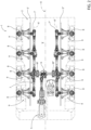
Figure 1 is a schematic plan view of a vehicle comprising a first embodiment of the distribution system according to the present invention; -
Figure 2 is a schematic plan view of a vehicle comprising a second embodiment of the distribution system according to the present invention; -
Figure 3 is a schematic plan view of a vehicle comprising a third embodiment of the distribution system according to the present invention; -
Figure 4 is a schematic sectional view of an axle of the distribution system according to the invention; -
Figure 5 is a schematic sectional view of a first embodiment of a portion of the distribution system according to the invention; -
Figure 6 is a schematic sectional view of a second embodiment of a portion of the distribution system according to the invention; and -
Figure 7 is a schematic sectional view of a first embodiment of a portion of the distribution system according to the invention. -
Figure 1 shows avehicle 1 of a special type, such as a fire-fighting, military, emergency heavy vehicle, including achassis 2 extending along an axis A and provided with a pair ofspars 3', 3" extending parallel to the axis A and spaced from it. -
Vehicle 1 also includes anengine module 5, advantageously an internal combustion engine and adistribution system 7 configured to operationally connectengine module 5 to a plurality ofwheels 8 carried bychassis 2. - In detail,
vehicle 1 also comprises anaxle 6 rigidly connectingspars 3', 3" to each other and forming part ofdistribution system 7. - Advantageously,
vehicle 1 is of the hybrid type and comprises at least one electric machine M', M", in the case described two electric machines M', M", operationally interposed betweenengine module 5,distribution system 7 andwheels 8. In the embodiment described, electric machines M', M" are carried byaxle 6. - In particular, electric machines M' , M" are electrically connected, by cable or wireless, to an energy storage system of
vehicle 1, not depicted, such as vehicular batteries, configured to exchange energy with electric machines M', M", respectively to supply it or to store it depending on the operation of electric machines M', M" by engine, i.e. using electrical energy to produce torque or vice versa from generators. - Advantageously, moreover, each
wheel 8 is carried by arespective suspension system 9 made externally torespective spar 3', 3". Eachsuspension system 9 is advantageously operationally separated from the other so that eachwheel 8 is independent in movement from the others. - In particular, it is noted that
engine module 5 is placed in front along the axis A andaxle 6 is placed at the back adjacent thereto so as to leave a rear space V between spars 3' . 3". - With reference to the longitudinal axis A, said rear free space V is transversely delimited by spars 3', 3'', in front delimited by
axle 6 and open at the back. - In detail, a first pair of
wheels 8 is directly connected toaxle 6, a second pair ofwheels 8 is placed in front of the first pair ofwheels 8 and the remaining pairs ofwheels 8 are placed at the back of the second pair ofwheels 8. - In the embodiment of
Figure 1 there is a third pair ofrear wheels 8, in the embodiment ofFigure 2 there are a third and a fourth pair ofrear wheels 8 one at the back of the other and in the embodiment ofFigure 3 there are a third, a fourth and a fifth pair ofrear wheels 8 one at the back of the other. - Consequently, between the embodiments of
Figures 1 ,2 and3 , the extension along the axis A of the rear free space V varies. - In particular,
distribution system 7 comprises a first and asecond branch 7', 7" extending along respective axes A', A" parallel to the longitudinal axis A, therefore to first and tosecond spar 3', 3" and operationally connected toaxle 6 so as to define with this an "H" shape configured to receive torque fromengine module 5, and advantageously from the at least one electric machine M', M" and exchange this torque withwheels 8 as described below. - It is noted how the control seat of
vehicle 1 can advantageously be placed anteriorly with respect toaxle 6 in greater detail betweenengine module 5 anddistribution system 7 so as to leave the portion of vehicle behindaxle 6 completely free. - In
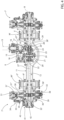
Figure 4 axle 6 of the distribution system according to the invention is shown in detail. -
Axle 6 comprises ahousing 11 extending along an axis B transverse to the axis A and advantageously connecting spars 3', 3'', and defining aspace 12 housing part ofdistribution system 7. - In detail,
distribution system 7 comprises aninput shaft 13 carried by the engine system and configured to provide torque via afirst transfer system 21 and asecond transfer system 21 to a pair ofdrive axles 27', 27" operationally connected to the second pair ofwheels 8, as described below. - Advantageously both first and
second transfer systems - In detail,
first transfer system 13 comprises afirst shaft 16 rigidly connected toinput shaft 13 and connected via a gear to asupport shaft 18. Advantageously, the gear is a bevel type gear and comprises afirst gear wheel 17 rigidly carried byfirst shaft 16 and asecond gear wheel 19 carried bysupport shaft 18 and meshing withfirst gear wheel 17. -
Support shaft 18, rotatably carried byhousing 11, is operationally connected to driveaxles 27', 27" viasecond transfer system 21, configured as a differential system. - In detail, said
differential system 21 comprises aplanetary carrier 23 meshing with agear wheel 22 rigidly carried bysupport shaft 18 and driving apin 24, advantageously a cross pin, adapted to bring a plurality ofsatellites 25 free to rotate on it. -
Satellites 25 are configured to mesh with a first and a second gear wheel 26', 26'', advantageously conical, carried by respective ends ofdrive axles 27', 27". - Preferably,
distribution system 7 comprises locking means 28 ofdifferential system 21 configured to lock the operation ofdifferential transfer system 21, i.e. by rotatinggear wheels 26', 26" at the same speed. - In detail, said locking means 28 comprise a sleeve 28' carried by drive
axle 27" and configured to slide on it along its longitudinal axis between a position of non-coupling one of gear wheels 26', 26'' and a coupling position that makes this and driveaxle 27" integral with each other. - Locking means 28 are actuated by actuator means 29. Still in the embodiment described, actuator means 29 are of pneumatic type and not further described for brevity's sake.
- The opposite ends of
drive axles 27', 27" are connected towheels 8 as detailed below, as well as via atransfer system 30, with differential, to first andsecond branches 7', 7" ofdistribution system 7 at an intermediate point with respect to their ends and advantageously to electric machines M', M'' further placed internally with respect todifferential transfer system 30. - For the sake of brevity, reference is made below only to the connection with
second branch 7", the other being mirrored and made similarly. - In detail,
differential transfer system 30 is configured to operationally connect drive axle 27' to a first and asecond output shaft other wheels 8 ofvehicle 1. - In detail, first and
second output shafts wheel differential transfer system 30. - The latter comprises in detail a plurality of
satellites 39 carried byrespective pins 38 meshing with drive axle 27' and connected by a rotating planetary carrier.Satellites 39 also mesh with the aforementioned gear wheels 35', 36' carried rotationally free betweenhousing 11 and drive axle 27' . - Note, in detail, how first and
second output shafts respective gear wheels 35. - Advantageously,
first output shaft 31 is made of twoportions 31', 31" selectively connectable to each other. In particular,distribution system 7 comprises selector means 33 configured to allow selective coupling between the two portions 31', 31'' . Advantageously,distribution system 7 comprises actuation means 34 configured to move selector means 33 to allow or not the coupling of the twoportions 31', 31". - Advantageously in the form described, said selector means 33 comprise a sleeve carried by one of two portions 31', 31'' and configured to slide on it along its longitudinal axis between a position of non-coupling with other portion 31', 31'' and a coupling position that makes two
portions 31', 31" integral with each other. Still in the embodiment described, actuator means 34 are of pneumatic type and not further described for brevity's sake. - Preferably,
distribution system 7 comprises locking means 40 of the differential system configured to lock the operation ofdifferential transfer system 30, i.e. by rotating gear wheels 35', 36' at the same speed. - In detail, said locking means 40 comprise a
sleeve 41 carried by drive axle 27' and configured to slide on it along its longitudinal axis between a position of non-coupling one ofgear wheels 35', 36 and a coupling position that makes this and drive axle 27' integral with each other. - Locking means 40 are actuated by actuator means 42. Still in the embodiment described, actuator means 42 are of pneumatic type and not further described for brevity's sake.
-
Figures 5 and6 show twoconnection assemblies wheel 8 along arespective branch 7' , 7" . -
Figure 5 shows afirst connection assembly 50 comprising adifferential transfer system 60 configured to connect together a first and a second shaft 64', 64'' forming part of branch 7', 7'' with awheel shaft 51 connected to awheel 8. - First and second shafts 64', 64'' are advantageously connected to one of first and
second shafts axle 6 or to other first and second shafts 64', 64'' of afurther connection assembly 50. - In particular,
differential transfer system 60 comprises a first gear wheel 63' and a second gear wheel 63'' respectively one integral with asupport shaft 52 and one integral withsecond shaft 64".Differential transfer system 60 further comprises a plurality ofpins 61, connected to each other by a movable planetary carrier, each supporting arespective satellite 62 configured to mesh with aforesaid first andsecond gear wheels 63', 63".Pins 61 are also configured to mesh with first shaft 64'. - Preferably,
distribution system 7 comprises locking means 65 of the differential system configured to lock the operation ofdifferential transfer system 60, i.e. by rotatingshafts 52 and 64'' at the same speed. - In detail, said locking means 65 comprise a
sleeve 66 carried by shaft 64' and configured to slide on it along its longitudinal axis between a position of non-coupling theshaft 52 and a coupling portion that makes this and shaft 64' integral with each other. - Locking means 65 are actuated by actuator means 67. Still in the embodiment described, actuator means 67 are of pneumatic type and not further described for brevity's sake.
-
Support shaft 52 is operationally connected towheel shaft 51 via agear 53, for example a bevel gear comprising a first gear wheel 52' integral withwheel shaft 51 and asecond gear wheel 53" integral withsupport shaft 52. -
Figure 6 shows asecond connection assembly 70 configured to connect awheel shaft 81 connected to awheel 8 and arotating shaft 82 forming part ofbranch 7', 7". - In particular, rotating
shaft 82 is operationally connected towheel shaft 81 via atransfer system 80 withgear 83, for example a bevel gear comprising a first gear wheel 83' integral withwheel shaft 81 and asecond gear wheel 83" integral withrotating shaft 82. - In particular,
first connection assembly 50 may be provided between branch 7', 7'' andfirst wheels 8 andlast wheels 8 posteriorly with respect toaxle 6 i.e. the third pairs of wheels in the embodiment ofFigure 1 , the fourth pair of wheels in the embodiment ofFigure 2 or the fifth pair of wheels in the embodiment ofFigure 3 and thesecond connection assembly 70 may be provided between branch 7', 7'' and the third pair of wheels in the embodiment ofFigure 2 or the third and fourth pair of wheels in the embodiment ofFigure 3 . - As best visible in
Figure 7 ,distribution system 7 also comprises atransfer system 90 operationally interposed between aninput shaft 85 to awheel 8 and its hub so as to vary its torque/speed. - In particular, according to what is depicted in
Figure 7 ,input shaft 85 is carried by drive axle 27'' ofFigure 4 . Clearly,transfer system 90 can be made in anywheel 8 ofvehicle 1. - Advantageously,
transfer system 90 is of the epicyclic type and comprises asun gear 91 rigidly carried byinput shaft 85, a plurality ofsatellites 92 meshing with the sun gear and carried byrespective pins 92 integral with aplanetary carrier 93 rigidly carried by the hub ofwheel 8. - Still referring to
Figure 7 , an exemplary embodiment ofsuspension system 9 forwheel 8 is shown in detail. As already mentioned,suspension system 9 connects awheel 8 independently of the others tochassis 2 and externally tospars 3', 3". - In the embodiment described,
suspension system 9 comprises anelastic device 101 configured to connect the hub ofwheel 8 to a portion ofchassis 2 to absorb a force acting on a vertical axis (i.e. perpendicular to the axes A, B), such as a hydraulic cylinder or a gas spring or a helical spring. - Furthermore,
suspension system 9 comprises aretention element 102 configured to limit longitudinal and transverse movements of the hub ofwheel 8 allowing a vertical movement thereof. - In detail,
retention element 102 comprises a V-shaped element, advantageously with the tip facing away with respect tochassis 2, i.e. with the vertex at the hub ofwheel 8 and therefore comprising a first rod 102' and a second rod 102'' joined together in a "V" shape. -
Rods 102', 102" are respectively connected to their ends by respectivemovable connections wheel hub 8. - As can be seen from the drawings,
vehicle 1 also comprises a steering system 105, optionally provided with eachwheel 8 and configured to allow it to rotate around the aforementioned vertical axis. Such steering system 105 may comprise anarm 106 adapted to act on one end of asteering knuckle 107 of the hub ofwheel 8, as per se known and not further described. - The operation of the distribution system and vehicle according to the invention described above is as follows.
- In a first operating condition, purely with traction drive via
engine module 5, the torque is provided by this towardsaxle 6 and primarily distributed to driveaxles 27', 27". In particular, this distribution is carried out through first transfer system 14 which varies the torque/speed to the seconddifferential transfer system 21 which allows the torque to be provided, optionally at different relative speeds, to driveaxles 27', 27". From these, the torque is provided to the second pair ofwheels 8 and viashafts branches 7', 7" ofdistribution system 7, i.e. towards the pair of front wheels and towards the at least one pair of rear wheels. In particular, thanks to selector means 33 it is possible to connect or not the front wheels in a configuration with all drive wheels. Still, it is possible or not to lock the differential function ofdifferentials respective locking systems branch 7 it is transferred through one ofconnection assemblies subsequent shaft 64" androtating shaft 51 connected to awheel 8 via a differential system 60 (as in theconnection assembly 50 ofFigure 5 ) or directly via a gear 83 (as in theconnection assembly 70 ofFigure 6 ). Furthermore, eachwheel 8 is connected torespective input shaft 85 viamechanism 90 which varies torque and speed via the passage betweensun gear 91,satellites 92 andplanetary carrier 94 which is integral with the wheel hub. - In a second operating, boost, condition, electric machines M', M" can lie, one or both, on
drive axles 27', 27" providing additional torque to at least one ofbranches 7', 7". The path of the torque alongdistribution system 7 is not traced again, for brevity's sake being analogous. - In a third operating, charging, condition, electric machines M', M" receive torque from branches 7', 7'' due to the dragging of the vehicle, with a reverse torque path similar to the previous one and therefore not described for brevity's sake, thus braking a pair of drive axles and
braking vehicle 1. - From the foregoing, the advantages of a wheel hub for a vehicle axle comprising an integrated reduction system according to the invention are evident.
- Thanks to the proposed system that defines an "H" shape, it is possible to provide a useful rear space that allows
vehicle 1 to obtain great versatility and therefore to be adoptable in different emergency, fire-fighting and military configurations. - In particular, thanks to its composition,
chassis 2 is particularly robust and compact. Furthermore, its integration withdistribution system 7 makes it possible to keep the latter protected from any impacts or collisions from the external environment by being protected byspars 3 or byaxle 6. - Still,
distribution system 7 thanks to the distribution to anywheel 7 independently of the others and thanks toindependent suspension system 9 essentially allows to provide a vehicle usable in any ground condition, even off-road, in conditions of mud or debris as the torque can be easily distributed where necessary and where the wheels can move relative to the chassis freely with respect to each other. - In particular, the above is synergistically reinforced by the presence of multiple differential blocks and front drive wheel connection systems for "all drive wheels" configuration.
- Thanks to the fact that the torque can be provided by the engine module or by electric machines M', M", it is possible to provide both an emergency redundancy system if one of the engine module or electric machines M', M" has a malfunction, a boost system and an energy recovery braking system.
- The applications and versatility of the vehicle are therefore increased as well as its consumption reduced.
- Finally, it is clear that modifications and variants can be made to the wheel hub of vehicle axle comprising an integrated reduction system according to the present invention which, however, do not fall outside the scope of protection defined by the claims.
- Clearly, the systems of gear, differentials, selectors and differential blocks and respective actuators can be made differently.
- Still, the expected shapes and the number of pairs of wheels may vary. In addition, as mentioned, the vehicle can be of any type for special use.
- Still, clearly, mechanical connection elements or rolling supports or lubrication elements not per se pertinent to the present inventions and clear to a person skilled in the art and not mentioned for brevity's sake may have been omitted in the description.
- Likewise, the types of gear wheels and the number of their teeth have not been indicated and may vary for this purpose.
Claims (20)
- Vehicle (1) of a special type comprising a chassis (2) movable on the ground via a plurality of wheels (8), said chassis comprising a pair of spars (3', 3'') extending parallel to a longitudinal axis (A) of said vehicle (1), said vehicle (1) comprising an engine module (5) configured to provide torque to said plurality of wheels (8) and a distribution system (7) operationally connected between said engine module (5) and said plurality of wheels (8) to distribute said torque, said distribution system (7) comprising an axle (6) and a first and a second branch (7', 7"), said axle (6) comprising a pair of drive axles (27', 27") operationally connected to an input shaft (13) driven by said engine module (5), said first and said second branches (7', 7") each driven by a respective of said drive axles (27', 27"), said first and second branches extending along respective axes (A', A") parallel and spaced from said longitudinal axis (A), said first and second branches (7', 7") each being placed adjacent and internally to a respective spar (3', 3"),
wherein said drive axles (27', 27") are operationally connected to the respective branch (7', 7") via a differential system (30) configured to allow a different driving speed rotation between a first and a second connecting shaft (31, 32) of said branches (7', 7"). - Vehicle according to claim 1, wherein said engine module (5) is placed anteriorly with respect to said longitudinal axis (A) with respect to said axle (6).
- Vehicle according to claim 2, wherein said drive axles (27', 27") are operationally connected to a second pair of wheels (8), said vehicle further comprising a first pair of wheels (8) driven by said first and second branch (7', 7") and placed anteriorly with respect to said axle (6) .
- Vehicle according to claim 3, wherein said vehicle (1) can assume one of the following three configurations:- in a first configuration it includes a third pair of wheels (8) driven by said first and second branches (7', 7"); or- in a second configuration it includes a third and a fourth pair of wheels (8) driven by said first and second branches (7', 7"); or- in a third configuration it includes a third, a fourth and a fifth pair of wheels (8) driven by said first and second branches (7', 7").
- Vehicle according to one of claims 1 to 4, wherein said vehicle (1) defines a free space (V) transversally delimited by said branches (7', 7") and longitudinally delimited by said axle (6) and open at the back.
- Vehicle according to one of claims 1 to 5, further comprising at least one electric machine (M' , M") operationally connected to said drive axles (27', 27") upstream of said branches (7', 7").
- Vehicle according to one of the previous claims, wherein said axle (6) includes a housing (11) defining a space (12) housing said drive axle (27', 27") and connecting said spars (3', 3").
- Vehicle according to one of the previous claims, wherein said distribution system (7) includes a first transfer system (14) and a second transfer system (21) operationally interposed between said input shaft (13) and said drive axle (27', 27"), said first transfer system (14) comprising a gear, said second transfer system (21) being a differential system, driven by one of the gear wheels of said first transfer system gear (14).
- Vehicle according to one of the previous claims, wherein said first connecting shaft (31) is made in two portions (31', 31") selectively connectable to each other via selector means (33).
- Vehicle according to claim 8 or 9, wherein said differential system (30) includes pins (39) supporting a plurality of satellites (38) meshing with respective gear wheels (35', 36') meshing with respective gear wheels (35, 36) integral with said first and a second connecting shaft (31, 32), said pins (39) being driven by a respective drive axle (27', 27").
- Vehicle according to claim 6, wherein said at least one electric machine (M', M") is interposed between said drive axle (27', 27") between said second transfer system (21) and said differential system (30).
- Vehicle according to one of the previous claims, wherein said distribution system (7) includes a first connection assembly (50) to connect one of said wheels (8) to said transmission branch (7', 7"), said first connection assembly (50) comprising a differential mechanism (60).
- Vehicle according to claim 12, wherein said differential mechanism (60) includes a plurality of pins (61) driving satellites (62) operationally connected to a wheel shaft (51) and to a second shaft (64") of said branch (7', 7"), said pins (61) being dragged by a first shaft (64') of said branch (7', 7").
- Vehicle according to claim 13, wherein said satellites (62) mesh with a support shaft (52) operationally connected to said wheel shaft (51) via a gear (53).
- Vehicle according to one of the previous claims, wherein said distribution system (7) includes a second connection assembly (70) to connect one of said wheels (8) to said transmission branch (7', 7"), said second connection assembly (70) comprising a gear transfer system (80).
- Vehicle according to claims 12 and 15 in combination with claim 4, wherein:- in said first configuration said third pair of wheels (8) is connected to said branch (7', 7") via said first connection assembly (50) and said first pair of wheels (8) is connected to said branch (7', 7") via said second connection assembly (70);- in said second configuration said third pair of wheels (8) is connected to said branch (7', 7") via said first connection assembly (50), said first and said fourth pair of wheels (8) are connected to said branch (7', 7") via said second connection assembly (70);- in said third configuration said third and fourth pairs of wheels (8) are connected to said branch (7', 7") via said first connection assembly (50), said first and said fifth pairs of wheels (8) are connected to said branch (7', 7") via said second connection assembly (70).
- Vehicle according to one of the previous claims, wherein said differential systems (21, 30, 60) include differential locking systems.
- Vehicle according to one of the previous claims, wherein each wheel (8) is supported by a respective suspension system (9) independent of every other wheel (8).
- Vehicle according to claim 18, wherein said suspension system (9) is placed externally to said spars (3', 3") and includes a vertical retention element (101) and a longitudinal and transversal retention element (102) operationally connecting a hub of said wheel (8) to said spar (3', 3'').
- Vehicle according to any of the previous claims, wherein said wheels (8) are driven by a respective shaft (27', 27", 85), said wheels (8) comprising an epicyclic transfer system (90) operationally connecting said shaft (27', 27", 85) to the hub of said wheels (8).
Applications Claiming Priority (1)
| Application Number | Priority Date | Filing Date | Title |
|---|---|---|---|
| IT102023000024930A IT202300024930A1 (en) | 2023-11-23 | 2023-11-23 | IMPROVED TORQUE DISTRIBUTION SYSTEM FOR A VEHICLE |
Publications (1)
| Publication Number | Publication Date |
|---|---|
| EP4559713A1 true EP4559713A1 (en) | 2025-05-28 |
Family
ID=89897715
Family Applications (2)
| Application Number | Title | Priority Date | Filing Date |
|---|---|---|---|
| EP24214499.6A Pending EP4559712A1 (en) | 2023-11-23 | 2024-11-21 | Improved torque distribution system for a vehicle |
| EP24214540.7A Pending EP4559713A1 (en) | 2023-11-23 | 2024-11-21 | Improved torque distribution system for a vehicle |
Family Applications Before (1)
| Application Number | Title | Priority Date | Filing Date |
|---|---|---|---|
| EP24214499.6A Pending EP4559712A1 (en) | 2023-11-23 | 2024-11-21 | Improved torque distribution system for a vehicle |
Country Status (2)
| Country | Link |
|---|---|
| EP (2) | EP4559712A1 (en) |
| IT (1) | IT202300024930A1 (en) |
Citations (7)
| Publication number | Priority date | Publication date | Assignee | Title |
|---|---|---|---|---|
| US2299006A (en) * | 1939-06-05 | 1942-10-13 | Floyd De L Brown | Automotive vehicle |
| US3566825A (en) * | 1967-06-05 | 1971-03-02 | Walter Ruf | Amphibious armored vehicle |
| US3809004A (en) * | 1972-09-18 | 1974-05-07 | W Leonheart | All terrain vehicle |
| US3930550A (en) * | 1974-08-15 | 1976-01-06 | The United States Of America As Represented By The Secretary Of The Army | Vehicle drive and suspension |
| US20050205329A1 (en) * | 2004-02-25 | 2005-09-22 | Shimon Fanger-Vexler | Vehicle and vehicle drive-through suspension arm |
| US20060169514A1 (en) * | 2004-12-21 | 2006-08-03 | Lim Stephen T | Axle arrangement for a vehicle |
| US20070272453A1 (en) * | 2003-10-03 | 2007-11-29 | J.C.L. Technology L.L.C. | Power Plant and Driveline for Vehicles |
-
2023
- 2023-11-23 IT IT102023000024930A patent/IT202300024930A1/en unknown
-
2024
- 2024-11-21 EP EP24214499.6A patent/EP4559712A1/en active Pending
- 2024-11-21 EP EP24214540.7A patent/EP4559713A1/en active Pending
Patent Citations (7)
| Publication number | Priority date | Publication date | Assignee | Title |
|---|---|---|---|---|
| US2299006A (en) * | 1939-06-05 | 1942-10-13 | Floyd De L Brown | Automotive vehicle |
| US3566825A (en) * | 1967-06-05 | 1971-03-02 | Walter Ruf | Amphibious armored vehicle |
| US3809004A (en) * | 1972-09-18 | 1974-05-07 | W Leonheart | All terrain vehicle |
| US3930550A (en) * | 1974-08-15 | 1976-01-06 | The United States Of America As Represented By The Secretary Of The Army | Vehicle drive and suspension |
| US20070272453A1 (en) * | 2003-10-03 | 2007-11-29 | J.C.L. Technology L.L.C. | Power Plant and Driveline for Vehicles |
| US20050205329A1 (en) * | 2004-02-25 | 2005-09-22 | Shimon Fanger-Vexler | Vehicle and vehicle drive-through suspension arm |
| US20060169514A1 (en) * | 2004-12-21 | 2006-08-03 | Lim Stephen T | Axle arrangement for a vehicle |
Also Published As
| Publication number | Publication date |
|---|---|
| EP4559712A1 (en) | 2025-05-28 |
| IT202300024930A1 (en) | 2025-05-23 |
Similar Documents
| Publication | Publication Date | Title |
|---|---|---|
| KR102580735B1 (en) | Axle assembly for low-floor vehicles | |
| US11400807B2 (en) | Electric axle assembly | |
| EP1626889B1 (en) | An articulated vehicle, an articulation device and a drive transmission | |
| JP6279102B2 (en) | Integrated steering drive shaft and electric vehicle for automobile | |
| US11376956B2 (en) | Tandem wheel assembly with pivot dampening system | |
| US5950750A (en) | Drive arrangement for a motor vehicle | |
| US11884150B2 (en) | Tandem wheel assembly with wheel end brake assembly | |
| EP3290250B1 (en) | Modular torque compensated walking beam assembly for work vehicle | |
| US11938812B2 (en) | Tandem wheel assembly and tandem wheel kit | |
| US11760196B2 (en) | Tandem wheel assembly with wheel end adjustment | |
| CN101557958A (en) | Steer drive for tracked vehicles | |
| US20050045390A1 (en) | Skid steer vechicle with bogie suspension | |
| CN101203399B (en) | vehicle | |
| WO2013174825A1 (en) | Hybrid drive train for a vehicle, vehicle, method of operation and retrofitting | |
| EP4559712A1 (en) | Improved torque distribution system for a vehicle | |
| CN105082997B (en) | A kind of sectionalized tractor | |
| EP4399111B1 (en) | Traction assembly for a vehicle | |
| RU2641951C1 (en) | Multifunctional vehicle | |
| JP4177012B2 (en) | Traveling vehicle | |
| JPS60139533A (en) | Four-wheel drive vehicle | |
| EP4238802B1 (en) | Improved torque distributor system among axles of a heavy vehicle | |
| DE102008030578A1 (en) | Device for driving and suspension influencing drive wheel of vehicle, has electric motors couplable with gear arrangement, where power of motors is divided for vehicle drive and vehicle suspension based on actual operating condition | |
| EP1495899B1 (en) | Traveling vehicle | |
| RU130261U1 (en) | SWIVEL-VEHICLE VEHICLE (OPTIONS) | |
| EP4534318A1 (en) | Improved torque distributor system among axles of a heavy vehicle |
Legal Events
| Date | Code | Title | Description |
|---|---|---|---|
| PUAI | Public reference made under article 153(3) epc to a published international application that has entered the european phase |
Free format text: ORIGINAL CODE: 0009012 |
|
| STAA | Information on the status of an ep patent application or granted ep patent |
Free format text: STATUS: THE APPLICATION HAS BEEN PUBLISHED |
|
| AK | Designated contracting states |
Kind code of ref document: A1 Designated state(s): AL AT BE BG CH CY CZ DE DK EE ES FI FR GB GR HR HU IE IS IT LI LT LU LV MC ME MK MT NL NO PL PT RO RS SE SI SK SM TR |
|
| STAA | Information on the status of an ep patent application or granted ep patent |
Free format text: STATUS: REQUEST FOR EXAMINATION WAS MADE |
|
| STAA | Information on the status of an ep patent application or granted ep patent |
Free format text: STATUS: EXAMINATION IS IN PROGRESS |
|
| 17P | Request for examination filed |
Effective date: 20251126 |
|
| 17Q | First examination report despatched |
Effective date: 20251203 |