EP4559631A1 - Stabilisierte bearbeitungsmaschine, stabilisierungskit für eine bearbeitungsmaschine und verfahren zur steuerung einer solchen maschine - Google Patents
Stabilisierte bearbeitungsmaschine, stabilisierungskit für eine bearbeitungsmaschine und verfahren zur steuerung einer solchen maschine Download PDFInfo
- Publication number
- EP4559631A1 EP4559631A1 EP24207385.6A EP24207385A EP4559631A1 EP 4559631 A1 EP4559631 A1 EP 4559631A1 EP 24207385 A EP24207385 A EP 24207385A EP 4559631 A1 EP4559631 A1 EP 4559631A1
- Authority
- EP
- European Patent Office
- Prior art keywords
- head
- tensioners
- machining
- cables
- machining machine
- Prior art date
- Legal status (The legal status is an assumption and is not a legal conclusion. Google has not performed a legal analysis and makes no representation as to the accuracy of the status listed.)
- Withdrawn
Links
Images


Classifications
-
- B—PERFORMING OPERATIONS; TRANSPORTING
- B25—HAND TOOLS; PORTABLE POWER-DRIVEN TOOLS; MANIPULATORS
- B25J—MANIPULATORS; CHAMBERS PROVIDED WITH MANIPULATION DEVICES
- B25J9/00—Program-controlled manipulators
- B25J9/003—Program-controlled manipulators having parallel kinematics
- B25J9/0078—Program-controlled manipulators having parallel kinematics actuated by cables
-
- B—PERFORMING OPERATIONS; TRANSPORTING
- B25—HAND TOOLS; PORTABLE POWER-DRIVEN TOOLS; MANIPULATORS
- B25J—MANIPULATORS; CHAMBERS PROVIDED WITH MANIPULATION DEVICES
- B25J11/00—Manipulators not otherwise provided for
- B25J11/005—Manipulators for mechanical processing tasks
- B25J11/0055—Cutting
-
- B—PERFORMING OPERATIONS; TRANSPORTING
- B25—HAND TOOLS; PORTABLE POWER-DRIVEN TOOLS; MANIPULATORS
- B25J—MANIPULATORS; CHAMBERS PROVIDED WITH MANIPULATION DEVICES
- B25J19/00—Accessories fitted to manipulators, e.g. for monitoring, for viewing; Safety devices combined with or specially adapted for use in connection with manipulators
- B25J19/0008—Balancing devices
-
- B—PERFORMING OPERATIONS; TRANSPORTING
- B25—HAND TOOLS; PORTABLE POWER-DRIVEN TOOLS; MANIPULATORS
- B25J—MANIPULATORS; CHAMBERS PROVIDED WITH MANIPULATION DEVICES
- B25J9/00—Program-controlled manipulators
- B25J9/16—Program controls
- B25J9/1628—Program controls characterised by the control loop
-
- G—PHYSICS
- G05—CONTROLLING; REGULATING
- G05B—CONTROL OR REGULATING SYSTEMS IN GENERAL; FUNCTIONAL ELEMENTS OF SUCH SYSTEMS; MONITORING OR TESTING ARRANGEMENTS FOR SUCH SYSTEMS OR ELEMENTS
- G05B19/00—Program-control systems
- G05B19/02—Program-control systems electric
- G05B19/18—Numerical control [NC], i.e. automatically operating machines, in particular machine tools, e.g. in a manufacturing environment, so as to execute positioning, movement or co-ordinated operations by means of program data in numerical form
- G05B19/404—Numerical control [NC], i.e. automatically operating machines, in particular machine tools, e.g. in a manufacturing environment, so as to execute positioning, movement or co-ordinated operations by means of program data in numerical form characterised by control arrangements for compensation, e.g. for backlash, overshoot, tool offset, tool wear, temperature, machine construction errors, load, inertia
-
- B—PERFORMING OPERATIONS; TRANSPORTING
- B23—MACHINE TOOLS; METAL-WORKING NOT OTHERWISE PROVIDED FOR
- B23Q—DETAILS, COMPONENTS, OR ACCESSORIES FOR MACHINE TOOLS, e.g. ARRANGEMENTS FOR COPYING OR CONTROLLING; MACHINE TOOLS IN GENERAL CHARACTERISED BY THE CONSTRUCTION OF PARTICULAR DETAILS OR COMPONENTS; COMBINATIONS OR ASSOCIATIONS OF METAL-WORKING MACHINES, NOT DIRECTED TO A PARTICULAR RESULT
- B23Q11/00—Accessories fitted to machine tools for keeping tools or parts of the machine in good working condition or for cooling work; Safety devices specially combined with or arranged in, or specially adapted for use in connection with, machine tools
- B23Q11/0032—Arrangements for preventing or isolating vibrations in parts of the machine
-
- G—PHYSICS
- G05—CONTROLLING; REGULATING
- G05B—CONTROL OR REGULATING SYSTEMS IN GENERAL; FUNCTIONAL ELEMENTS OF SUCH SYSTEMS; MONITORING OR TESTING ARRANGEMENTS FOR SUCH SYSTEMS OR ELEMENTS
- G05B2219/00—Program-control systems
- G05B2219/30—Nc systems
- G05B2219/39—Robotics, robotics to robotics hand
- G05B2219/39215—Adaptive control with stabilizing compensation
Definitions
- the present invention relates to the field of machining machines (or robots).
- machine and “robot” (or “machine tool” or even “automaton”) are used interchangeably in the present application to designate the robotic devices used for the design of parts, whether by milling, welding, 3D printing, etc.
- machining is therefore used in the present application to designate factory manufacturing by robots or automatons and is not limited to the type of tool equipping the machine.
- the present invention relates to a stabilized machining machine and a stabilization kit for machining machines.
- machining machines are generally large robotic arms mounted on a base and having a movable end (called “head” in the present application) which carries the machining tools (cutting, milling, printing, welding tool, etc.) and moves in the three directions of space in order to machine the parts with various orientations.
- head a movable end
- robot arm refers to all types of robotic machining machines with multiple axes, such as for example robotic arms or linear axis machines, etc.
- An aim of the present invention is therefore to overcome at least certain drawbacks of the prior art by proposing a stabilized machining machine.
- the tensioners and the cables are configured in pairs, with at least three pairs distributed around said machining head and, within each pair, the tensioners are arranged on either side of the machining head, so that the tension force exerted on said machining head by each of the tensioners has at least one component in the opposite direction to that of the other tensioner of the same pair.
- control unit controls the movement of each of the tensioners and the tension of each of the cables so that the forces exerted by the different cables on the machining head compensate each other, preferably so that their sum is zero.
- each of said cables is mounted on the head using a clip free to pivot depending on the inclination of the cables relative to the horizontal.
- each of said fasteners is configured to move freely on a plate secured to the head, along a circular path centered on said head, so that the pivots are positioned according to the orientation and length of each of the cables.
- said support comprises at least one wall having a circular or elliptical cross-section surrounding said robotic arm.
- said support comprises at least one wall having a rectangular or square section surrounding said robotic arm.
- said support comprises at least three posts perpendicular to the ground and distributed around said robotic arm, preferably equidistant from each other.
- each of said means for moving said tensioners on said support comprises a motorized carriage controlled by said control unit to move on a rail in order to adjust the height of said tensioner relative to the ground.
- the stabilizer also includes means for lateral movement of the tensioners, to adjust their respective positions around the head.
- said adjustable means for tensioning said cables comprise at least one cable winder controlled by said control unit and forming said tensioner.
- An aim of the present invention is to overcome at least certain drawbacks of the prior art by proposing a stabilization kit for machining machines, in order to improve the stability and/or the precision of the machining machines of the prior art.
- a stabilization kit for a machining machine characterized in that it comprises a stabilizer according to various embodiments.
- An aim of the present invention is to overcome at least certain drawbacks of the prior art by proposing a method for controlling and/or stabilizing a machining machine, in order to improve the stability and/or precision of the machining machines of the prior art.
- the tensioners (20) and cables (21) are configured in pairs, with at least three pairs distributed around said machining head (10). In this case, within each pair, the tensioners (20) are arranged on either side of the machining head (10), so that the tension force exerted on said machining head (10) by each of the tensioners (20) has at least one component in the opposite direction to that of the other tensioner of the same pair.
- control unit controls the movement of each of the tensioners (20) and the tension of each of the cables (21) so that the forces exerted by the different cables on the machining head (10) compensate each other, preference for their sum to be zero.
- the control unit distributes the cables in the same plane, preferably horizontal.
- the distribution is three-dimensional so that the machining head is stabilized vertically and transversely.
- the tensioners and cables are arranged in pairs, so that the tensions they exert on the machining head can compensate each other within the same pair, at least for one component, for example vertical. Indeed, by providing pairs comprising an upper tensioner and a lower tensioner, it is easier to ensure that the vertical components compensate each other (an upward tension component and a downward tension, respectively). Thus, within the same pair, the vertical components compensate each other while the horizontal components will be compensated from one part to another.
- the pairs rather concern two tensioners diametrically opposed with respect to the head, but it is simpler to design the system with pairs of tensioners aligned vertically.
- the upper tensioner can move vertically on a rail, but it remains aligned with respect to the lower tensioner which moves vertically on its own rail.
- the lower tensioner moves vertically on its own rail while the upper tensioner remains stationary, but these tensioners of the same pair preferably remain vertically aligned to facilitate compensation of tension forces and control by the control unit.
- both tensioners both move vertically on a single common rail.
- This common stabilization plane (by tensioning) may depend on the position and inclination of the head but also on the type of machining carried out and the resulting forces.
- this plane may depend on a possible pivoting machining support (14) on which the part to be machined can be arranged, as well known to those skilled in the art and illustrated for example in the Figure 7 .
- the tension of the cables can be adjusted according to the type of machining in progress and in particular the tools used (cutting, milling, printing, welding tool, etc.) since they do not all have the same torques and do not exert the same forces on the head.
- a "hybrid" machining machine is envisaged, with in particular a 3D printing head, to complete the type of operations possible with the machine.
- various types of sensors will be used by the control unit to correctly adjust the various parameters that come into account for stabilization.
- at least one tension sensor eg, tensiometer
- at least one tension sensor eg, tensiometer
- the stabilizer preferably includes at least one electronic level arranged at least at the level of the head.
- the stabilizer will therefore include at least one level positioned for example at least on the plate (12), but preferably also on the cables (21), for example near the tensioners, to check the correct inclination of the cables, following the positioning of the tensioners according to the inclination detected at the head.
- the control unit can thus control the various devices using various types of sensors and that the examples provided here are not limiting.
- each of said cables (21) is mounted on the head (10) using a clip (210) free to pivot depending on the inclination of the cables (21) relative to the horizontal.
- a clip may be formed by a pivot (for example with a spherical head retained in a housing, allowing the movement of the cable in a cone whose apex is centered on this spherical head), but since these are cable clips, this freedom of movement may simply be provided by the cable itself. The use of a pivot will nevertheless limit the wear of the cables by subjecting them less to the forces which are concentrated at the level of this clip.
- each of said fasteners (210) is configured to move freely on a plate (12) secured to the head (10), along a circular path centered on said head (10), so that the fasteners (210) are positioned according to the orientation and length of each of the cables (21).
- Casters are for example provided to facilitate movement on the plate (12) forming for example a crown on which the fasteners are retained, the casters of which ensure the mobility and solidity of the assembly.
- the position of the attachments (210) of the cables on the head can adapt automatically to the orientation of the cables, which is preferably obtained simply by the fact that the attachments move on a common crown or on respective arcs of circles in order to allow a movement of the attachment which remains centered relative to the center of the head.
- the stabilizer also comprises means (24) for lateral movement of the tensioners (20), to adjust their respective positions around the head (10), for example by moving the posts or the rails on which the carriages move.
- the [ Fig 3 ] And [ Fig 5 ] show illustrative and non-limiting examples of such means (24) of movement.
- the posts move, for example using motorized trolleys on rails (24) (arranged on the ground in these examples but they can be on the ceiling and preferably on the ground and the ceiling in order to stiffen the assembly).
- the rails follow a curvilinear path but a rectilinear path is of course also possible.
- the means (23) of movement of the tensioners in height are the only ones necessary for good balancing but their association with such means (24) of lateral (transverse) displacement makes it possible to adjust the position of the tensioners in two dimensions and to better distribute the tension forces relative to the head, in particular when the positions potentially taken by the head (10) are likely to interfere with the path of the cables (which can then be moved using these lateral displacement means).
- said support (2) comprises at least three posts perpendicular to the ground and distributed around said robotic arm (1), preferably equidistant from each other.
- the number of posts may vary depending on the number of cables (and tensioners, etc.). In general, three cables may be sufficient (for example as illustrated in the [ Fig 5 ]), provided that they are correctly distributed around the head (preferably equidistant from each other), but four or more cables may be provided, in particular to obtain even more stability and/or to facilitate integration, in particular in cabins usually housing machining machines.
- said support (2) comprises at least one wall having a rectangular or square section surrounding said robotic arm (1).
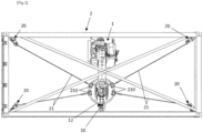
- the cables and tensioners are preferably four in number, distributed at the corners of the structure. Illustrative examples of such embodiments are shown in the [ Fig 1 ] And [ Fig 2 ] showing a cabin, such as a container, housing the machining machine within a support formed of four vertical walls distributed to form a rectangular parallelepiped and provided with reinforcement posts. Reinforcements may also be provided at the top (at the summit or on the roof) of the structure forming the support (2), to stabilize the assembly and in particular to prevent any unwanted movement of the tensioners, for example as shown in an illustrative and non-limiting manner on the [ Fig 2 ].
- said support (2) comprises at least one wall having a circular or elliptical cross-section surrounding said robotic arm (1).
- the cabin is of circular or elliptical section and the radius may vary according to the range of the head relative to the base.
- it is possible that it is not the wall which defines a circular path, but rather that it is the means (24) of transverse movement, for example as shown in an illustrative and non-limiting manner on the [ Fig 5 ]. In this example, three posts move on a circular rail (24) centered on the machine tool.
- the [ Fig 3 ] represents, in an illustrative and non-limiting manner, another variant where the transverse displacement means (24) are formed by arcs of a circle centered on the machine tool. Indeed, whether the system comprises three or four supports (or more), it is generally not necessary to go all the way around the machine to allow good positioning of the cables.
- the transverse displacement means (24) can be means of movement on the walls of the container.
- each of said means (23) for moving said tensioners (20) on said support (2) comprises a motorized carriage (230) controlled by said control unit (CU) to move on a rail (231) in order to adjust the height of said tensioner (20) relative to the ground.
- said adjustable means (22) for tensioning said cables (21) comprise at least one cable winder controlled by said control unit (CU) and forming said tensioner (20).
- a winder may for example be a ball screw.
- the [ Fig 4 ] represents an illustrative and non-limiting example of the tensioners (20) with their adjustable tension means (22) and the vertical displacement means (23) comprising a carriage (230) moving on a rail (231).
- the preferred embodiments are those where the tensioners and cables are distributed around the head to compensate for the tensions in the three dimensions of space.
- 4 Upper tensioners (and cables) are arranged above the horizontal plane in which the center of the head is located and 4 lower tensioners (and cables) are arranged below this plane.
- the different tensioners make it possible to compensate for the forces exerted on the head both vertically and horizontally.
- Their distribution around the head in a horizontal plane and their height allow the control unit to adjust the forces exerted according to the position of the machining head and/or the type of machining in progress. This makes it possible to limit the risks of resulting movements and therefore to improve the precision of the machine and/or to limit its sizing (and therefore its cost).
Landscapes
- Engineering & Computer Science (AREA)
- Robotics (AREA)
- Mechanical Engineering (AREA)
- Human Computer Interaction (AREA)
- Manufacturing & Machinery (AREA)
- Physics & Mathematics (AREA)
- General Physics & Mathematics (AREA)
- Automation & Control Theory (AREA)
- Manipulator (AREA)
Applications Claiming Priority (2)
| Application Number | Priority Date | Filing Date | Title |
|---|---|---|---|
| FR2312830A FR3155452A1 (fr) | 2023-11-21 | 2023-11-21 | Machine d’usinage stabilisée, kit de stabilisation pour machine d’usinage et procédé de pilotage d’une telle machine |
| FR2402266A FR3155453A1 (fr) | 2023-11-21 | 2024-03-06 | Machine d’usinage stabilisée, kit de stabilisation pour machine d’usinage et procédé de pilotage d’une telle machine |
Publications (1)
| Publication Number | Publication Date |
|---|---|
| EP4559631A1 true EP4559631A1 (de) | 2025-05-28 |
Family
ID=93117416
Family Applications (1)
| Application Number | Title | Priority Date | Filing Date |
|---|---|---|---|
| EP24207385.6A Withdrawn EP4559631A1 (de) | 2023-11-21 | 2024-10-18 | Stabilisierte bearbeitungsmaschine, stabilisierungskit für eine bearbeitungsmaschine und verfahren zur steuerung einer solchen maschine |
Country Status (1)
| Country | Link |
|---|---|
| EP (1) | EP4559631A1 (de) |
Citations (6)
| Publication number | Priority date | Publication date | Assignee | Title |
|---|---|---|---|---|
| US20130013109A1 (en) * | 2011-04-07 | 2013-01-10 | Kuka Roboter Gmbh | Method And Handling System For Automatically Moving A Gravity-Compensated Load Body |
| US20140290417A1 (en) * | 2011-05-13 | 2014-10-02 | Zenrobotics Oy | Method and apparatus for moving and positioning a gripping unit, and a robot provided with gripping unit |
| US10791275B2 (en) * | 2017-09-25 | 2020-09-29 | The Boeing Company | Methods for measuring and inspecting structures using cable-suspended platforms |
| US20210069897A1 (en) * | 2019-04-08 | 2021-03-11 | 10087530 Canada Inc. D/B/A Rbot9 Automation | Cable robot |
| CN113319866A (zh) * | 2021-06-10 | 2021-08-31 | 潍坊新松机器人自动化有限公司 | 一种智能机器人负载平衡吊具 |
| US20210276177A1 (en) * | 2018-06-14 | 2021-09-09 | Cameron Reed McROBERTS | Apparatus and method for cable-driven robotics |
-
2024
- 2024-10-18 EP EP24207385.6A patent/EP4559631A1/de not_active Withdrawn
Patent Citations (6)
| Publication number | Priority date | Publication date | Assignee | Title |
|---|---|---|---|---|
| US20130013109A1 (en) * | 2011-04-07 | 2013-01-10 | Kuka Roboter Gmbh | Method And Handling System For Automatically Moving A Gravity-Compensated Load Body |
| US20140290417A1 (en) * | 2011-05-13 | 2014-10-02 | Zenrobotics Oy | Method and apparatus for moving and positioning a gripping unit, and a robot provided with gripping unit |
| US10791275B2 (en) * | 2017-09-25 | 2020-09-29 | The Boeing Company | Methods for measuring and inspecting structures using cable-suspended platforms |
| US20210276177A1 (en) * | 2018-06-14 | 2021-09-09 | Cameron Reed McROBERTS | Apparatus and method for cable-driven robotics |
| US20210069897A1 (en) * | 2019-04-08 | 2021-03-11 | 10087530 Canada Inc. D/B/A Rbot9 Automation | Cable robot |
| CN113319866A (zh) * | 2021-06-10 | 2021-08-31 | 潍坊新松机器人自动化有限公司 | 一种智能机器人负载平衡吊具 |
Similar Documents
| Publication | Publication Date | Title |
|---|---|---|
| KR101834001B1 (ko) | 측지 측량 시 삼각대의 지면 고정 장치 | |
| FR3054466A3 (fr) | Centre d’usinage pour profiles metalliques | |
| FR2474619A1 (fr) | Systeme mobile a trois ou quatre degres de liberte de mouvement | |
| FR2541616A1 (fr) | Etabli de reparation de carrosseries d'automobiles | |
| EP0194217B1 (de) | Industrieroboter vom sphärischen Typ | |
| EP4559631A1 (de) | Stabilisierte bearbeitungsmaschine, stabilisierungskit für eine bearbeitungsmaschine und verfahren zur steuerung einer solchen maschine | |
| EP2603415B1 (de) | Montageverfahren für eine vordere aufhängung und einen hilfsträger mit dem chassis eines kraftfahrzeugs | |
| FR3155453A1 (fr) | Machine d’usinage stabilisée, kit de stabilisation pour machine d’usinage et procédé de pilotage d’une telle machine | |
| FR2956106A1 (fr) | Vehicule elevateur pour le positionnement d'une charge en hauteur | |
| FR3035028A1 (fr) | "ensemble de train arriere roulant integrant un moteur semi-porteur pour vehicule automobile" | |
| EP4034446A1 (de) | Gelenkvorrichtung für ein gelenkfahrzeug, entsprechendes fahrzeug und einstellverfahren | |
| CA2663869A1 (fr) | Dispositif pour l'usinage en plafond de pieces fixes | |
| EP1362664A2 (de) | Hochgeschwindigheitfräsmaschine | |
| EP3064418A1 (de) | Förderwagen | |
| EP1692070B1 (de) | Wagen und portalkran mit solch einem wagen | |
| EP4425278A1 (de) | Uhrwerkbank und vorderarmstütze für eine uhrwerkbank | |
| FR2465540A1 (fr) | Tour sur fosse pour le profilage des roues sur essieux ferroviaires montes | |
| EP2265487A1 (de) | Vorrichtung zur positionierung von elementen einer motorfahrzeug-vorder- und hinterverkleidung | |
| EP2365925A1 (de) | Tragestruktur für einen fahrzeugaufbau mit stützfuss mit mobiler platte | |
| JPS59110498A (ja) | 溶接ト−チ搬送台車 | |
| FR2816230A1 (fr) | Machine-outil a plusieurs axes | |
| FR2473925A1 (fr) | Perfectionnement aux machines-outils, notamment aux fraiseuses type aviation, dites 5 axes | |
| FR2755050A1 (fr) | Dispositif de suspension d'outils a commande manuelle dans une chaine d'assemblage | |
| FR2550980A1 (fr) | Dispositif de supportage d'un capteur pour une machine automatique et son application a une telle machine | |
| BE572568A (de) |
Legal Events
| Date | Code | Title | Description |
|---|---|---|---|
| PUAI | Public reference made under article 153(3) epc to a published international application that has entered the european phase |
Free format text: ORIGINAL CODE: 0009012 |
|
| STAA | Information on the status of an ep patent application or granted ep patent |
Free format text: STATUS: THE APPLICATION HAS BEEN PUBLISHED |
|
| AK | Designated contracting states |
Kind code of ref document: A1 Designated state(s): AL AT BE BG CH CY CZ DE DK EE ES FI FR GB GR HR HU IE IS IT LI LT LU LV MC ME MK MT NL NO PL PT RO RS SE SI SK SM TR |
|
| STAA | Information on the status of an ep patent application or granted ep patent |
Free format text: STATUS: THE APPLICATION IS DEEMED TO BE WITHDRAWN |
|
| 18D | Application deemed to be withdrawn |
Effective date: 20251129 |