EP4559331A1 - Aerosol generation device and control method therefor, and method for generating aerosols - Google Patents
Aerosol generation device and control method therefor, and method for generating aerosols Download PDFInfo
- Publication number
- EP4559331A1 EP4559331A1 EP23842432.9A EP23842432A EP4559331A1 EP 4559331 A1 EP4559331 A1 EP 4559331A1 EP 23842432 A EP23842432 A EP 23842432A EP 4559331 A1 EP4559331 A1 EP 4559331A1
- Authority
- EP
- European Patent Office
- Prior art keywords
- heating region
- heating
- aerosol
- temperature
- generation device
- Prior art date
- Legal status (The legal status is an assumption and is not a legal conclusion. Google has not performed a legal analysis and makes no representation as to the accuracy of the status listed.)
- Pending
Links
Images



Classifications
-
- A—HUMAN NECESSITIES
- A24—TOBACCO; CIGARS; CIGARETTES; SIMULATED SMOKING DEVICES; SMOKERS' REQUISITES
- A24F—SMOKERS' REQUISITES; MATCH BOXES; SIMULATED SMOKING DEVICES
- A24F40/00—Electrically operated smoking devices; Component parts thereof; Manufacture thereof; Maintenance or testing thereof; Charging means specially adapted therefor
- A24F40/40—Constructional details, e.g. connection of cartridges and battery parts
- A24F40/46—Shape or structure of electric heating means
-
- A—HUMAN NECESSITIES
- A24—TOBACCO; CIGARS; CIGARETTES; SIMULATED SMOKING DEVICES; SMOKERS' REQUISITES
- A24F—SMOKERS' REQUISITES; MATCH BOXES; SIMULATED SMOKING DEVICES
- A24F40/00—Electrically operated smoking devices; Component parts thereof; Manufacture thereof; Maintenance or testing thereof; Charging means specially adapted therefor
- A24F40/10—Devices using liquid inhalable precursors
-
- A—HUMAN NECESSITIES
- A24—TOBACCO; CIGARS; CIGARETTES; SIMULATED SMOKING DEVICES; SMOKERS' REQUISITES
- A24F—SMOKERS' REQUISITES; MATCH BOXES; SIMULATED SMOKING DEVICES
- A24F40/00—Electrically operated smoking devices; Component parts thereof; Manufacture thereof; Maintenance or testing thereof; Charging means specially adapted therefor
- A24F40/40—Constructional details, e.g. connection of cartridges and battery parts
-
- A—HUMAN NECESSITIES
- A24—TOBACCO; CIGARS; CIGARETTES; SIMULATED SMOKING DEVICES; SMOKERS' REQUISITES
- A24F—SMOKERS' REQUISITES; MATCH BOXES; SIMULATED SMOKING DEVICES
- A24F40/00—Electrically operated smoking devices; Component parts thereof; Manufacture thereof; Maintenance or testing thereof; Charging means specially adapted therefor
- A24F40/50—Control or monitoring
- A24F40/51—Arrangement of sensors
-
- A—HUMAN NECESSITIES
- A24—TOBACCO; CIGARS; CIGARETTES; SIMULATED SMOKING DEVICES; SMOKERS' REQUISITES
- A24F—SMOKERS' REQUISITES; MATCH BOXES; SIMULATED SMOKING DEVICES
- A24F40/00—Electrically operated smoking devices; Component parts thereof; Manufacture thereof; Maintenance or testing thereof; Charging means specially adapted therefor
- A24F40/50—Control or monitoring
- A24F40/57—Temperature control
-
- A—HUMAN NECESSITIES
- A24—TOBACCO; CIGARS; CIGARETTES; SIMULATED SMOKING DEVICES; SMOKERS' REQUISITES
- A24F—SMOKERS' REQUISITES; MATCH BOXES; SIMULATED SMOKING DEVICES
- A24F7/00—Mouthpieces for pipes; Mouthpieces for cigar or cigarette holders
-
- A—HUMAN NECESSITIES
- A24—TOBACCO; CIGARS; CIGARETTES; SIMULATED SMOKING DEVICES; SMOKERS' REQUISITES
- A24F—SMOKERS' REQUISITES; MATCH BOXES; SIMULATED SMOKING DEVICES
- A24F40/00—Electrically operated smoking devices; Component parts thereof; Manufacture thereof; Maintenance or testing thereof; Charging means specially adapted therefor
- A24F40/20—Devices using solid inhalable precursors
Definitions
- This application relates to the field of electronic vaporization technologies, and particularly, to an aerosol generation device and a control method therefor, and a method for generating an aerosol.
- An existing aerosol generation device mainly has a far-infrared coating and a conductive coating coated on an outer surface of a base body, and the energized far-infrared coating emits far-infrared rays that penetrate the base body and heat an aerosol-forming substrate in the base body. Because of having strong penetrability, the far-infrared rays can penetrate the periphery of the aerosol-forming substrate to enter the interior, so that the aerosol-forming substrate is heated evenly.
- a problem of the aerosol generation device is that a preheating time of the aerosol-forming substrate is long, and when inhaling an aerosol, a user feels hot in the mouth, which affects a use experience of the user.
- This application provides an aerosol generation device and a control method therefor, and a method for generating an aerosol, to resolve problems of a long preheating time and the burnt mouth during inhalation in the existing aerosol generation device.
- an aerosol generation device configured to heat an aerosol-forming substrate to generate an aerosol, the aerosol-generating substrate including a first part of aerosol-generating substrate and a second part of aerosol-generating substrate; the aerosol generation device includes:
- a control method for an aerosol generation device is further provided, the aerosol generation device being configured to heat an aerosol-forming substrate to form an aerosol, and the aerosol generation device including a power source, a first heating region for heating a first part of aerosol-forming substrate, and a second heating region for heating a second part of aerosol-forming substrate, the aerosol-generating substrate including a first part of aerosol-generating substrate and a second part of aerosol-generating substrate; the control method includes:
- the aerosol generation device and the control method therefor and the method for generating an aerosol provided in this application, by controlling, during the first partial period of the control period of the heater, only the first heating region to start heating and the second heating region not to start heating, and controlling, during the remaining partial period, the first heating region and the second heating region to start heating simultaneously, a preheating time of an aerosol-forming substrate is shortened, the problem that a user feels hot in the mouth when inhaling an aerosol is avoided, and a vaping and use experience of the user is improved.
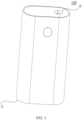
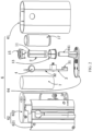
- FIG. 1 and FIG. 2 show an aerosol generation device 100, including a housing assembly 6 and a heater 11, according to an implementation of this application.
- the heater 11 is arranged in the housing assembly 6.
- the heater 11 can radiate infrared rays to heat an aerosol-forming substrate to generate an inhalable aerosol.
- the housing assembly 6 includes an outer shell 61, a fixing shell 62, a base, and a bottom cap 64, and both the fixing shell 62 and the base are fixed in the outer shell 61, where the base is configured to fix the heater 11, the base is arranged in the fixing shell 62, and the bottom cap 64 is arranged at a distal end 9 of the outer shell 61 and covers the outer shell 61.
- the fixing shell 62 is provided with an insertion port, and the aerosol-forming substrate is removably received or inserted into the heater 11 through the insertion port.
- the base includes a base 15 sleeved on an upper end of the heater 11 and a base 13 sleeved on a lower end of the heater 11. Both the base 15 and the base 13 are arranged in the fixing shell 62.
- An air inlet tube 641 is protrudingly arranged on the bottom cap 64. One end of the base 13 away from the base 15 is connected to the air inlet tube 641.
- the base 15, the heater 11, the base 13, and the air inlet tube 641 are coaxially arranged.
- the heater 11 and the base 15 as well as the base 13 are sealed by seals, the base 13 and the air inlet tube 641 are also sealed, and the air inlet tube 641 is in communication with outside air to facilitate smooth air intaking during vaping by a user.
- the aerosol generation device 100 further includes a circuit board 3 and a battery core 7.
- the fixing shell 62 includes a front shell 621 and a rear shell 622, the front shell 621 is fixedly connected to the rear shell 622, the circuit board 3 and the battery core 7 are both arranged in the fixing shell 62, and the battery core 7 is electrically connected to the circuit board 3.
- a button 4 is protrudingly arranged on the outer shell 61, and the heater 11 can be energized or unenergized by pressing the button 4.
- the circuit board 3 is further connected to a charging interface 31, the charging interface 31 is exposed on the bottom cap 64, and the user may charge or upgrade the aerosol generation device 100 through the charging interface 31, to ensure continuous use of the aerosol generation device 100.
- the aerosol generation device 100 further includes a heat insulation tube 17, the heat insulation tube 17 is arranged in the fixing shell 62, the heat insulation tube 17 is sleeved on the periphery of the heater 11, and the heat insulation tube 17 can prevent a lot of heat from being transferred to the outer shell 61 and causing the user to feel hot on a hand.
- the heat insulation tube includes a heat insulation material, and the heat insulation material may be heat insulation glue, aerogel, aerogel felt, asbestos, aluminum silicate, calcium silicate, diatomite, zirconium oxide, or the like.
- the heat insulation tube may also be a vacuum heat insulation tube.
- An infrared ray reflective coating may be further formed in the heat insulation tube 17, to reflect the infrared rays radiated by the heater 11 toward the aerosol-forming substrate, thereby improving the heating efficiency.
- the aerosol generation device 100 further includes a temperature sensor 2, such as an NTC temperature sensor, configured to detect a real-time temperature of the heater 11 and transmit the detected real-time temperature to the circuit board 3.
- the circuit board 3 adjusts a magnitude of a current flowing through the heater 11 based on the real-time temperature.
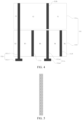
- FIG. 3 and FIG. 4 show heater according to an implementation of this application.
- the heater 11 includes: a base body 110, which may be made of a high temperature-resistant and transparent material such as quartz glass, ceramics, or mica, or may be made of another material having high infrared ray transmittance such as a high temperature-resistant material whose infrared ray transmittance is greater than 95%, which is not specifically limited herein.
- the base body 110 is approximately tubular, and preferably, in a shape of a round tube.
- An internal hollow part of the base body 110 defines or forms a cavity for receiving the aerosol-forming substrate.
- An inner diameter of the base body 110 ranges from 7 mm to 14 mm, or ranges from 7 mm to 12 mm, or ranges from 7 mm to 10 mm.
- the aerosol-forming substrate is a substrate that can release a volatile compound that can form an aerosol. Such a volatile compound may be released by heating the aerosol-forming substrate.
- the aerosol-forming substrate may be solid, liquid, or include solid and liquid components.
- the aerosol-forming substrate may be carried on a carrier or a support through absorption, coating, impregnation, or another manner.
- the aerosol-forming substrate may conveniently be a part of an aerosol-generating product.
- the aerosol-forming substrate may include nicotine.
- the aerosol-forming substrate may include tobacco, for example, may include a tobacco-containing material including a volatile tobacco-flavor compound.
- the volatile tobacco-flavor compound is released from the aerosol-forming substrate when the aerosol-forming substrate is heated.
- the aerosol-forming substrate may include at least one aerosol-forming agent, and the aerosol-forming agent may be any suitable known compound or a mixture of compounds. In use, the compound or the mixture of compounds facilitates formation of a dense and stable aerosol and is substantially resistant to thermal degradation at an operating temperature of an aerosol-generating system.
- a suitable aerosol forming agent includes, but is not limited to: polyol such as triethylene glycol, 1,3-butanediol, or glycerin; ester of polyol such as glyceryl monoacetate, glyceryl diacetate, or glyceryl triacetate; and fatty acid ester of monobasic carboxylic acid, dibasic carboxylic acid, or polybasic carboxylic acid such as dimethyl dodecane dibasic ester and dimethyl tetradecane dibasic ester.
- polyol such as triethylene glycol, 1,3-butanediol, or glycerin
- ester of polyol such as glyceryl monoacetate, glyceryl diacetate, or glyceryl triacetate
- fatty acid ester of monobasic carboxylic acid, dibasic carboxylic acid, or polybasic carboxylic acid such as dimethyl dodecane dibasic ester and dimethyl t
- An infrared electrothermal coating 111 is formed on a surface of the base body 110.
- the infrared electrothermal coating 111 may be formed on an outer surface of the base body 110, or may be formed on an inner surface of the base body 110.
- the infrared electrothermal coating 111 receives electric power to generate heat, to further radiate infrared rays of specific wavelengths, for example, far-infrared rays of 8 ⁇ m to 15 ⁇ m.
- infrared rays of specific wavelengths
- the wavelengths of the infrared rays match absorption wavelengths of the aerosol-forming substrate, energy of the infrared rays is easily absorbed by the aerosol-forming substrate.
- the wavelengths of the infrared rays are not limited.
- the infrared rays may be infrared rays of 0.75 ⁇ m to 1000 ⁇ m, and preferably, far-infrared rays of 1.5 ⁇ m to 400 ⁇ m.
- the infrared electrothermal coating 111 is formed on the outer surface of the base body 110.
- the infrared electrothermal coating 111 includes two infrared electrothermal coatings spaced apart, shown as an infrared electrothermal coating 111a and an infrared electrothermal coating 111b in the figure.
- the infrared electrothermal coating 111a is closer to a mouthpiece end 8 of the aerosol generation device 100 than the infrared electrothermal coating 111b is.
- the infrared electrothermal coating 111a is spaced apart from an upper end of the base body 110 by a spacing distance ranging from 0.2 mm to 1 mm, which facilitates manufacturing and production.
- a spacing distance between the infrared electrothermal coating 111a and the infrared electrothermal coating 111b ranges from 0.2 mm to 1 mm.
- the infrared electrothermal coating 111b is also spaced apart from a lower end of the base body 110 by a spacing distance ranging from 1 mm to 4 mm, which facilitates arrangement of conductive electrodes while preventing the lower end of the base body 110 from having an excessively high temperature.
- an axial extension length of the infrared electrothermal coating 111a may be the same as or different from an axial extension length of the infrared electrothermal coating 111b.
- the conductive element includes a conductive electrode 112a, a conductive electrode 112b, a conductive electrode 112c, a connecting electrode 112d, and a connecting electrode 112e that are arranged on the surface of the base body 110 at intervals.
- the conductive electrode 112a includes a coupling portion 112a1 extending along a circumferential direction of the base body 110 and a conductive portion 112a2 extending axially from the coupling portion 112a1 toward the upper end of the base body 110.
- the coupling portion 112a1 is arc-shaped, the coupling portion 112a1 is spaced apart from the infrared electrothermal coating 111b, and the coupling portion 112a1 is arranged between the infrared electrothermal coating 111b and the lower end of the base body 110.
- a wire may be soldered to the coupling portion 112a1 to form an electrical connection to a power source outside the heater 11, for example, the battery core 7 or a converted voltage of the battery core 7, or may be electrically connected to the power source by another electrical connector.
- the conductive portion 112a2 is strip-shaped, and has an axial extension length greater than the axial extension length of the infrared electrothermal coating 111b, and an upper end of the conductive portion 112a2 is flush with an upper end of the infrared electrothermal coating 111b.
- the conductive portion 112a2 keeps in contact with the infrared electrothermal coating 111b, to form an electrical connection.
- the conductive electrode 112b is strip-shaped, and its axial extension length is the same as the axial extension length of the infrared electrothermal coating 111a.
- the conductive electrode 112b keeps in contact with the infrared electrothermal coating 111a, to form an electrical connection.
- a structure of the conductive electrode 112c is similar to that of the conductive electrode 112a.
- a coupling portion 112c1 of the conductive electrode 112c is arranged between the infrared electrothermal coating 111b and the lower end of the base body 110.
- a conductive portion 112c2 is strip-shaped, but its axial extension length is greater than a sum of the axial extension lengths of the infrared electrothermal coating 111a and the infrared electrothermal coating 111b, and an upper end of the conductive portion 112c2 is flush with an upper end of the infrared electrothermal coating 111a.
- the conductive portion 112c2 keeps in contact with both the infrared electrothermal coating 111a and the infrared electrothermal coating 111b, to form electrical connections.
- Both the connecting electrode 112d and the connecting electrode e are strip-shaped and arranged in the infrared electrothermal coating 111b. Axial extension lengths of the connecting electrode 112d and the connecting electrode e are the same as the axial extension length of the infrared electrothermal coating 111b.
- the connecting electrode 112d is arranged between the conductive electrode 112a and the conductive electrode 112c.
- the connecting electrode 112d separates an infrared electrothermal coating between the conductive electrode 112a and the conductive electrode 112c into two infrared electrothermal sub-coatings (shown as B1 and B2 in FIG. 4 ) connected in series between the conductive electrode 112a and the conductive electrode 112c, and the infrared electrothermal sub-coating B1 and the infrared electrothermal sub-coating B2 are distributed along the circumferential direction of the base body 110.
- An equivalent resistance of the infrared electrothermal sub-coating B1 may be the same as or different from an equivalent resistance of the infrared electrothermal sub-coating B2.
- the connecting electrode 112e is also arranged between the conductive electrode 112a and the conductive electrode 112c.
- the connecting electrode 112e separates an infrared electrothermal coating between the conductive electrode 112a and the conductive electrode 112c into two infrared electrothermal sub-coatings (shown as B3 and B4 in FIG. 4 ) connected in series between the conductive electrode 112a and the conductive electrode 112c, and the infrared electrothermal sub-coating B3 and the infrared electrothermal sub-coating B4 are distributed along the circumferential direction of the base body 110.
- An equivalent resistance of the infrared electrothermal sub-coating B3 may be the same as or different from an equivalent resistance of the infrared electrothermal sub-coating B4.
- An overall resistance of the infrared electrothermal coating 111b can be reduced by arranging the connecting electrode 112d and the connecting electrode 112e.
- a plurality of connecting electrodes 112d and/or connecting electrodes 112e may be arranged between the conductive electrode 112a and the conductive electrode 112c as required, to separate the infrared electrothermal coating into a plurality of infrared electrothermal sub-coatings connected in series between the conductive electrode 112a and the conductive electrode 112c.
- two connecting electrodes 112d separate the infrared electrothermal coating into three infrared electrothermal sub-coatings connected in series between the conductive electrode 112a and the conductive electrode 112c.
- Equivalent resistances of the three infrared electrothermal sub-coatings may all be the same or different, or two of the three infrared electrothermal sub-coatings have a same equivalent resistance.
- a plurality of connecting electrodes 112d and/or connecting electrodes 112e may be arranged between the conductive electrode 112b and the conductive electrode 112c as required, to reduce an overall resistance of the infrared electrothermal coating 111a.
- a continuous conductive coating is used for the conductive electrode 112a, the conductive electrode 112b, the conductive electrode 112c, the connecting electrode 112d, and the connecting electrode 112e.
- the conductive coating may be a metal coating.
- the metal coating may include silver, gold, palladium, platinum, copper, nickel, molybdenum, tungsten, niobium, or an alloy material of the foregoing metals. Widths of the connecting electrode 112d and the connecting electrode 112e range 0.5 mm to 3 mm or from 0.5 mm and 2.5 mm, and in a specific example, may be 1 mm or 2 mm.
- a non-continuous conductive coating for example, a meshed conductive coating shown in FIG. 5 , may also be used as the connecting electrode 112d and the connecting electrode 112e.
- the connecting electrode 112d and/or the connecting electrode 112e may be arranged between the base body 110 and the infrared electrothermal coating 111b along a direction perpendicular to a surface of the base body 110.
- the infrared electrothermal coating 111b may be arranged between the base body 110 and the connecting electrode.
- the conductive portion 112a2 of the conductive electrode 112a and the conductive portion 112c2 of the conductive electrode 112c may also be arranged in this way.
- the infrared electrothermal coating 111a and the infrared electrothermal coating 111b can be independently controlled. Specifically, the power source can be controlled to provide heating power to the infrared electrothermal coating 111a and/or the infrared electrothermal coating 111b.
- the power source is first controlled to provide heating power to the infrared electrothermal coating 111a to heat an upper half part (a part corresponding to a region of the infrared electrothermal coating 111a) of the aerosol-generating product; and then, the power source is controlled to provide heating power to the infrared electrothermal coating 111b, to heat a lower half part (a part corresponding to a region of the infrared electrothermal coating 111b) of the aerosol-generating product.
- the power source is first controlled to provide heating power to the infrared electrothermal coating 111a to heat an upper half part (a part corresponding to a region of the infrared electrothermal coating 111a) of the aerosol-generating product.
- the power source is first controlled to provide heating power to the infrared electrothermal coating 111a, to heat the upper half part of the aerosol-generating product; and then, the power source is controlled to provide heating power to the infrared electrothermal coating 111a and the infrared electrothermal coating 111b simultaneously, to heat the entire aerosol-generating product.
- the power source is first controlled to provide heating power to the infrared electrothermal coating 111b, to heat the lower half part of the aerosol-generating product; and then, the power source is controlled to provide heating power to the infrared electrothermal coating 111a and the infrared electrothermal coating 111b simultaneously, to heat the entire aerosol-generating product.
- the conductive electrode 112b is electrically connected to a positive pole of the power source, and the coupling portion 112c1 is electrically connected to a negative pole of the power source.
- a current flows in from the conductive electrode 112b, and flows out from the conductive portion 112c2 after passing through an infrared electrothermal sub-coating A1 or an infrared electrothermal sub-coating A2 along the circumferential direction of the base body 110.
- the coupling portion 112a1 is electrically connected to a positive pole of the battery core 7, and the coupling portion 112c1 is electrically connected to a negative pole of the battery core 7.
- a current flows in from the conductive portion 112a2, and flows out from the conductive portion 112c2 after sequentially passing through the infrared electrothermal sub-coating B1 and the infrared electrothermal sub-coating B2 while sequentially passing through the infrared electrothermal sub-coating B4 and the infrared electrothermal sub-coating B3.
- the connecting electrode 112d and the connecting electrode 112e are not connected to the power source or the circuit outside the heater 11, that is, the connecting electrode 112d and the connecting electrode 112e are suspended, and a current cannot directly flow in from the connecting electrode 112c, and then flow out from the conductive portion 112b2 or the conductive portion 112a2.
- Existence of the connecting electrode 112d and the connecting electrode 112e can reduce the overall resistance of the infrared electrothermal coating 111b.
- a mark 113 is arranged in the region of the infrared electrothermal coating 111a.
- the mark 113 is used for positioning when the temperature sensor 2 is assembled.
- the temperature sensor 2 detects a real-time temperature of the region of the infrared electrothermal coating 111a and transmits the detected real-time temperature to the circuit board 3, and the circuit board 3 can control a temperature of the infrared electrothermal coating 111a and/or a temperature of the infrared electrothermal coating 111b based on the real-time temperature (which is described below).
- the heater 11 shown in FIG. 3 to FIG. 5 has a plurality of implementations after variation.
- the conductive electrode 112c with two electrode similar to the conductive electrode 112a and the conductive electrode 112b.
- the conductive electrode 112a, the conductive electrode 112b, and the conductive electrode 112c are all of a ring-shaped electrode structure, to separate the infrared electrothermal coating 111 into two, upper and lower infrared electrothermal coatings, and it is also feasible that one or more connecting electrodes of a ring-shaped structure can be arranged on the infrared electrothermal coating at a lower end.
- the conductive electrode 112a, the conductive electrode 112b, and the conductive electrode 112c are all of a spiral electrode structure, and it is also feasible that the connecting electrode is also of a spiral structure.
- FIG. 6 and FIG. 7 are schematic diagrams of another heater according to an implementation of this application.
- an axial extension length of the conductive portion 112a2 of the conductive electrode 112a is greater than a sum of the axial extension lengths of the infrared electrothermal coating 111a and the infrared electrothermal coating 111b, and an upper end of the conductive portion 112c2 is flush with an upper end of the infrared electrothermal coating 111a.
- the conductive electrode 112b and the conductive electrode 112d are both arranged between the conductive portion 112a2 of the conductive electrode 112a and the conductive portion 112c2 of the conductive electrode 112c, and the conductive electrode 112b and the conductive electrode 112d are both arranged in a region of the infrared electrothermal coating 111a.
- the infrared electrothermal coating 111a can be independently controlled, and the infrared electrothermal coating 111b cannot be independently controlled.
- the power source is first controlled through the conductive electrode 112b and the conductive electrode 112d to provide heating power to the infrared electrothermal coating 111a; and Then, the power source is controlled through the conductive electrode 112a and the conductive electrode 112c to provide the heating energy to the infrared electrothermal coating 111a and the infrared electrothermal coating 111b simultaneously.
- conductive portions (the conductive portion 112a2 of the conductive electrode 112a and the conductive portion 112c2 of the conductive electrode 112c) located between the conductive electrode 112b and the conductive electrode 112d are not energized, and the conductive portions are equivalent to the connecting electrodes in the examples in FIG. 3 and FIG. 4 , thereby reducing the overall resistance of the infrared electrothermal coating 111a, so that the infrared electrothermal coating 111a rapidly heats up, and can rapidly heat the upper half part of the aerosol-generating product, to achieve an objective of rapidly generating an aerosol.
- the conductive electrode 112a and the conductive electrode 112c are energized, the conductive electrode 112b and the conductive electrode 112d located between the conductive electrode 112a and the conductive electrode 112c are not energized, and are also equivalent to the connecting electrodes in the examples in FIG. 3 and FIG. 4 , thereby reducing the overall resistance of the infrared electrothermal coating 111a.
- the infrared electrothermal coating 111a and the infrared electrothermal coating 111b perform heating simultaneously or the infrared electrothermal coating 111 performs heating entirely
- existence of the conductive electrode 112b and the conductive electrode 112d reduces the overall resistance of the infrared electrothermal coating 111a, so that a temperature of the region of the infrared electrothermal coating 111a is raised, thereby changing a temperature field of the entire region of the infrared electrothermal coating 111.
- the temperature sensor 2 detects a real-time temperature of the region of the infrared electrothermal coating 111a and transmits the detected real-time temperature to the circuit board 3, and the circuit board 3 can control a temperature of the infrared electrothermal coating 111a and/or a temperature of the infrared electrothermal coating 111b based on the real-time temperature.
- FIG. 8 is a schematic diagram of a control curve of a heater according to an implementation of this application.
- a horizontal coordinate t represents a time
- 0 to t5 represent a control period of the region of the infrared electrothermal coating 111a
- a vertical coordinate T represents a temperature of the region of the infrared electrothermal coating 111a.
- a value of the temperature can be detected and fed back by the temperature sensor 2.
- the heating power provided by the power source is controlled based on temperature information of the region of the infrared electrothermal coating 111a.
- the initial temperature may be an ambient temperature, or may be a temperature greater than the ambient temperature.
- the first preset target temperature T1 ranges from 230°C to 300°C, preferably from 240°C to 300°C, more preferably from 240°C to 290°C, further preferably from 240°C to 280°C, and in a specific example, may be set to 250°C, 260°C, 270°C, or the like.
- the power source is controlled to provide maximum heating power, for example, heating power of 20 W to 40 W, to the infrared electrothermal coating 11 1a, so that the temperature of the region of the infrared electrothermal coating 111a can rapidly rise to the first preset target temperature T1.
- maximum heating power for example, heating power of 20 W to 40 W
- a start time point of the period 0 to t1 is a predetermined time point (including a time point at which a start signal is received, and a specific time point after the start signal is received) after a controller 32 receives the start signal, and at this time point, the controller 32 starts a control action.
- the start signal may be a signal generated by an airflow sensor or a signal generated by a button switch.
- the power source is controlled to provide heating power to the infrared electrothermal coating 111a, to keep the region of the infrared electrothermal coating 111a at the first preset target temperature T1.
- the power source is controlled to provide smaller heating power, for example, heating power of about 5 W to 15 W, to the infrared electrothermal coating 11 1a, so that the temperature of the region of the infrared electrothermal coating 111a is kept at the first preset target temperature T1.
- heating power for example, heating power of about 5 W to 15 W
- the first preset target temperature T1 means that the temperature of the region of the infrared electrothermal coating 111a may fluctuate around the target temperature T1, or the temperature of the region of the infrared electrothermal coating 111a does not exceed the target temperature T1.
- the period of 0 to t2 may also be referred to as a preheating stage or a preheating period, and a duration of this period ranges from 10s to 30s (including endpoint values), for example, may be 12s, 15s, 20s, 25s, 30s, or the like.
- Prompt information may be generated at the time point t2, to prompt a user that an aerosol is inhalable.
- a prompting manner includes, but is not limited to, sound, light, vibration, and the like.
- a period of t2 to t5 may also be referred to as an inhalation period, and in this period, the user may inhale an aerosol generated from an aerosol-generating substrate.
- the aerosol-generating product heated in this period is only a first part of the product corresponding to the infrared electrothermal coating 111a, and compared with the entire aerosol-generating product, the heated part is less, which, on the one hand, is beneficial to rapidly generating an inhalable aerosol, and on the other hand, avoids the problem that the user feels hot in the mouth when inhaling the aerosol (especially when inhaling the first puff of the aerosol) since a water content in the heated product is relatively reduced.
- the two parts of the product namely, the first part of the product corresponding to the infrared electrothermal coating 111a and the second part of the product corresponding to the region of the infrared electrothermal coating 111b, may include aerosol-forming substrates having a substantially same composition, or may include different components. There is no physical separation between the two parts of the product, or there is heat transfer between the two parts of the product.
- the temperature of the region of the infrared electrothermal coating 111a may be controlled to rise from the initial temperature to the first preset target temperature T1 with a slow rising trend (or a small curve slope).
- the power source is controlled to provide heating power to the infrared electrothermal coating 111a and the infrared electrothermal coating 111b simultaneously, to keep the region of the infrared electrothermal coating 111a at the first preset target temperature T1 under the allocated heating power.
- a duration of the period of t2 to t3 ranges from 30s to 50s, and in a specific example, may be 40s.
- the heating power provided by the power source to the infrared electrothermal coating 111 is allocated to two heating regions, namely, the infrared electrothermal coating 111a and the infrared electrothermal coating 111b.
- the infrared electrothermal coating 111a and the infrared electrothermal coating 111b are equivalent to two heating regions working in parallel. Therefore, a region with a smaller resistance obtains larger heating power, and conversely, a region with a larger resistance obtains smaller heating power.
- a resistance R111a of the infrared electrothermal coating 111a and a resistance R111b of the infrared electrothermal coating 111b are 3:2, and the heating power provided by the power source is 10 W, heating power allocated to the region of the infrared electrothermal coating 111a is 4 W, and heating power allocated to the region of the infrared electrothermal coating 111b is 6 W.
- the power source may be controlled to provide smaller heating power, for example, heating power of about 5 W to 15 W, to the infrared electrothermal coating 111, so that the temperature of the region of the infrared electrothermal coating 111a can be kept at the first preset target temperature T1 under the allocated heating power.
- the temperature of the region of the infrared electrothermal coating 111b can rapidly rise under the allocated heating power (although the power is small) and a temperature difference between the region of the infrared electrothermal coating 111a and the region of the infrared electrothermal coating 111b.
- the power source is controlled to provide heating power to the infrared electrothermal coating 111a and the infrared electrothermal coating 111b simultaneously, so that under allocated heating power, the temperature of the region of the infrared electrothermal coating 111a drops from the first preset target temperature T1 to a second preset target temperature T2 and be kept at the second preset target temperature T2.
- a duration of the period of t3 to t4 ranges from 30s to 50s, and in a specific example, may be 40s.
- a difference between the first preset target temperature T1 and the second preset target temperature T2 ranges from 10°C to 30°C, and in a specific example, may be 20°C.
- the heating power provided by the power source is allocated to the two regions, namely, the infrared electrothermal coating 111a and the infrared electrothermal coating 111b.
- the power source may be controlled to provide smaller heating power, for example, heating power of about 5 W to 15 W, to the infrared electrothermal coating 111, so that the temperature of the region of the infrared electrothermal coating 111a can, under the allocated heating power, drop from the first preset target temperature T1 to the second preset target temperature T2 and be kept at the second preset target temperature T2.
- smaller heating power for example, heating power of about 5 W to 15 W
- a temperature change of the region of the infrared electrothermal coating 111b is approximately the same as that of the region of the infrared electrothermal coating under the allocated heating power and a temperature difference between the region of the infrared electrothermal coating 111a and the region of the infrared electrothermal coating 111b.
- the power source is controlled to provide heating power to the infrared electrothermal coating 111a and the infrared electrothermal coating 111b simultaneously, so that under allocated heating power, the temperature of the region of the infrared electrothermal coating 111a drops from the second preset target temperature T2 to a third preset target temperature T3 and be kept at the third preset target temperature T3.
- a duration of the period of t4 to t5 ranges from 30s to 200s, and Generally, a difference between the second preset target temperature T2 and the third preset target temperature T3 ranges from 10°C to 20°C, and in a specific example, may be 15°C.
- the heating power provided by the power source is allocated to the region of the infrared electrothermal coating 111a and the region of the infrared electrothermal coating 111b.
- the power source may be controlled to provide smaller heating power, for example, heating power of about 5 W to 15 W, to the infrared electrothermal coating 111, so that the temperature of the region of the infrared electrothermal coating 111a can, under the allocated heating power, drop from the second preset target temperature T2 to the third preset target temperature T3 and be kept at the third preset target temperature T3.
- smaller heating power for example, heating power of about 5 W to 15 W
- a temperature change of the region of the infrared electrothermal coating 111b is approximately the same as that of the region of the infrared electrothermal coating under the allocated heating power and a temperature difference between the region of the infrared electrothermal coating 111a and the region of the infrared electrothermal coating 111b.
- the temperature difference between the region of the infrared electrothermal coating 111a and the region of the infrared electrothermal coating 111b depends on a resistance relationship between them. That is, if the two have the same resistance, there may be no temperature difference between the two; and if the two have different resistances, and a region with a smaller resistance is allocated with larger heating power, a temperature of the region with a smaller resistance is higher than a temperature of a region with a larger resistance. Based on this characteristic, in an actual operation process, an overall resistance of the infrared electrothermal coating 111b is reduced through the connecting electrode 112d and the connecting electrode 112e.
- the infrared electrothermal coating 111b helps the infrared electrothermal coating 111b obtain larger heating power during the period of t4 to t5, so that a temperature of the infrared electrothermal coating 111b is higher than a temperature of the infrared electrothermal coating 111a, thereby avoiding, while keeping consistency of vaping, a problem that a vaping experience of the user is degraded due to generation of a smaller amount of aerosol within the period t4 of to t5.
- a time during which a part of the product corresponding to the infrared electrothermal coating 111b is heated is later than a time during which a part of the product corresponding to the infrared electrothermal coating 111a is heated.
- Reducing the overall resistance of the infrared electrothermal coating 111b through the connecting electrode 112d and the connecting electrode 112e can ensure that the part of the product corresponding to the infrared electrothermal coating 111b is fully heated, in other words, a waste caused by the part of the product being not fully heated can be avoided.
- an aerosol-generating product has been or is considered to be consumed.
- the power source may be controlled to stop providing heating power to the infrared electrothermal coating 111.
- prompt information can be generated to prompt the user to replace the aerosol-generating product or that the aerosol-generating product has been consumed.
- a prompting manner includes, but is not limited to, sound, light, vibration, and the like.
- control curve shown in FIG. 8 can also be applied to other heating modes, for example, resistance heating, electromagnetic heating, and air heating.
- the power source is controlled to provide heating power to the infrared electrothermal coating 111a and the infrared electrothermal coating 111b simultaneously, to always keep the temperature of the region of the infrared electrothermal coating 111a at the first preset target temperature T1.
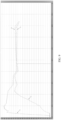
- FIG. 9 is a schematic diagram of an actual temperature curve of a heater according to an implementation of this application.
- the heater 11 is controlled by using the control curve shown in FIG. 8 , then a real-time temperature of the region of the infrared electrothermal coating 111a and a real-time temperature of the region of the infrared electrothermal coating 111b are respectively measured by two temperature sensors (an existing temperature sensor exemplified in FIG. 3 and FIG. 4 may be used as the temperature sensor of the region of the infrared electrothermal coating 111a), and finally, a schematic diagram of a time-temperature curve is obtained.
- S1 is a schematic diagram of a time-temperature curve of the region of the infrared electrothermal coating 111a
- S2 is a schematic diagram of a time-temperature curve of the region of the infrared electrothermal coating 111b.
- control curve indicates that the controller 32 controls, based on the curve, the heater 11 to work
- temperature curve indicates a relationship between a temperature generated by the heater 11 during working and a time.
- the controller 32 may be a part of the circuit board 3, and includes, but is not limited to, an MCU.
- the temperature of the region of the infrared electrothermal coating 111a rises from an initial temperature (about 28°C) to about 270°C.
- the region of the infrared electrothermal coating 111b does not start heating, the temperature of the region of the infrared electrothermal coating 111b slowly rises to about 80°C under an effect of heat transfer.
- the temperature of the region of the infrared electrothermal coating 111a drops to 230°C, and a temperature change of a region of the infrared electrothermal coating 111b is approximately the same as a temperature change of a region of the infrared electrothermal coating 111a.
- the temperature of the region of the infrared electrothermal coating 111a drops to 210°C, and a temperature change of a region of the infrared electrothermal coating 111b is also approximately the same as a temperature change of a region of the infrared electrothermal coating 111a. Then, the temperature of the region of the infrared electrothermal coating 111b and the temperature of the region of the infrared electrothermal coating 111a reach balance at about 140s.
- the temperature of the region of the infrared electrothermal coating 111b is significantly higher than the temperature of the region of the infrared electrothermal coating 111a.
Landscapes
- Resistance Heating (AREA)
Abstract
Description
- This application claims priority to
Chinese Patent Application No. 202210872754.0, entitled "AEROSOL GENERATION DEVICE AND CONTROL METHOD THEREFOR, AND METHOD FOR GENERATING AEROSOLS" filed with the China National Intellectual Property Administration on July 21, 2022 - This application relates to the field of electronic vaporization technologies, and particularly, to an aerosol generation device and a control method therefor, and a method for generating an aerosol.
- An existing aerosol generation device mainly has a far-infrared coating and a conductive coating coated on an outer surface of a base body, and the energized far-infrared coating emits far-infrared rays that penetrate the base body and heat an aerosol-forming substrate in the base body. Because of having strong penetrability, the far-infrared rays can penetrate the periphery of the aerosol-forming substrate to enter the interior, so that the aerosol-forming substrate is heated evenly.
- A problem of the aerosol generation device is that a preheating time of the aerosol-forming substrate is long, and when inhaling an aerosol, a user feels hot in the mouth, which affects a use experience of the user.
- This application provides an aerosol generation device and a control method therefor, and a method for generating an aerosol, to resolve problems of a long preheating time and the burnt mouth during inhalation in the existing aerosol generation device.
- According to an aspect of this application, an aerosol generation device is provided, configured to heat an aerosol-forming substrate to generate an aerosol, the aerosol-generating substrate including a first part of aerosol-generating substrate and a second part of aerosol-generating substrate; the aerosol generation device includes:
- a power source;
- a heater, including a first heating region for heating the first part of aerosol-forming substrate and a second heating region for heating the second part of aerosol-forming substrate; and
- a controller, configured to:
- control, during a first partial period of a control period of the heater, the power source to provide heating power only to the first heating region, to raise a temperature of the first heating region from an initial temperature to a first preset target temperature; and
- control, during a remaining partial period of the control period of the heater, the power source to provide heating power to the first heating region and the second heating region simultaneously, where
- a duration of the first partial period ranges from 10s to 30s.
- According to another aspect of this application, a control method for an aerosol generation device is further provided, the aerosol generation device being configured to heat an aerosol-forming substrate to form an aerosol, and the aerosol generation device including a power source, a first heating region for heating a first part of aerosol-forming substrate, and a second heating region for heating a second part of aerosol-forming substrate, the aerosol-generating substrate including a first part of aerosol-generating substrate and a second part of aerosol-generating substrate;
the control method includes: - controlling, during a first partial period of a control period of the heater, the power source to provide heating power only to the first heating region, to raise a temperature of the first heating region from an initial temperature to a first preset target temperature; and
- controlling, during a remaining partial period of the control period of the heater, the power source to provide heating power to the first heating region and the second heating region simultaneously, where
- a duration of the first partial period ranges from 10s to 30s.
- According to another aspect of this application, a method for generating an aerosol from an aerosol-generating substrate using an aerosol generation device,
- the aerosol-generating substrate including a first part of aerosol-generating substrate and a second part of aerosol-generating substrate, and the aerosol generation device including a first heating region for heating a first part of aerosol-forming substrate and a second heating region for heating a second part of aerosol-forming substrate, where
- the method includes:
- causing, during a first partial period of a control period of the heater, the first heating region to start heating and rise from an initial temperature to a first preset target temperature, and causing the second heating region not to start heating; and
- causing, during a remaining partial period of the control period of the heater, the first heating region and the second heating region to start heating simultaneously, where
- a duration of the first partial period ranges from 10s to 30s.
- According to the aerosol generation device and the control method therefor and the method for generating an aerosol provided in this application, by controlling, during the first partial period of the control period of the heater, only the first heating region to start heating and the second heating region not to start heating, and controlling, during the remaining partial period, the first heating region and the second heating region to start heating simultaneously, a preheating time of an aerosol-forming substrate is shortened, the problem that a user feels hot in the mouth when inhaling an aerosol is avoided, and a vaping and use experience of the user is improved.
- One or more embodiments are exemplarily described with reference to the corresponding figures in the accompanying drawings, and the descriptions are not to be construed as limiting the embodiments. Components in the accompanying drawings that have same reference numerals are represented as similar components, and unless otherwise particularly stated, the figures in the accompanying drawings are not drawn to scale.
-
FIG. 1 is a schematic diagram of an aerosol generation device according to an implementation of this application; -
FIG. 2 is a schematic exploded view of an aerosol generation device according to an implementation of this application; -
FIG. 3 is a schematic diagram of a heater according to an implementation of this application; -
FIG. 4 is a schematic diagram of an infrared electrothermal coating in a heater according to an implementation of this application after being unrolled; -
FIG. 5 is a schematic diagram of a connecting electrode according to an implementation of this application; -
FIG. 6 is a schematic diagram of another heater according to an implementation of this application; -
FIG. 7 is a schematic diagram of an infrared electrothermal coating in another heater according to an implementation of this application after being unrolled; -
FIG. 8 is a schematic diagram of a control curve of a heater according to an implementation of this application; and -
FIG. 9 is a schematic diagram of an actual temperature curve of a heater according to an implementation of this application. - For ease of understanding of this application, this application is described below in more detail with reference to accompanying drawings and specific implementations. It should be noted that, when an element is expressed as "being fixed to" another element, the element may be directly on the another element, or one or more intermediate elements may exist between the element and the another element. When an element is expressed as "being connected to" another element, the element may be directly connected to the another element, or one or more intermediate elements may exist between the element and the another element. The terms "upper", "lower", "left", "right", "inner", "outer", and similar expressions used in this specification are merely used for an illustrative purpose.
- Unless otherwise defined, meanings of all technical and scientific terms used in this specification are the same as those usually understood by a person skilled in the art to which this application belongs. The terms used in this specification of this application are merely intended to describe objectives of the specific implementations, and are not intended to limit this application. The term "and/or" used in this specification includes any or all combinations of one or more related listed items.
-
FIG. 1 andFIG. 2 show anaerosol generation device 100, including ahousing assembly 6 and aheater 11, according to an implementation of this application. Theheater 11 is arranged in thehousing assembly 6. Theheater 11 can radiate infrared rays to heat an aerosol-forming substrate to generate an inhalable aerosol. - The
housing assembly 6 includes anouter shell 61, afixing shell 62, a base, and abottom cap 64, and both thefixing shell 62 and the base are fixed in theouter shell 61, where the base is configured to fix theheater 11, the base is arranged in thefixing shell 62, and thebottom cap 64 is arranged at adistal end 9 of theouter shell 61 and covers theouter shell 61. Thefixing shell 62 is provided with an insertion port, and the aerosol-forming substrate is removably received or inserted into theheater 11 through the insertion port. - The base includes a
base 15 sleeved on an upper end of theheater 11 and abase 13 sleeved on a lower end of theheater 11. Both thebase 15 and thebase 13 are arranged in thefixing shell 62. Anair inlet tube 641 is protrudingly arranged on thebottom cap 64. One end of thebase 13 away from thebase 15 is connected to theair inlet tube 641. Thebase 15, theheater 11, thebase 13, and theair inlet tube 641 are coaxially arranged. In addition, theheater 11 and thebase 15 as well as thebase 13 are sealed by seals, thebase 13 and theair inlet tube 641 are also sealed, and theair inlet tube 641 is in communication with outside air to facilitate smooth air intaking during vaping by a user. - The
aerosol generation device 100 further includes acircuit board 3 and abattery core 7. Thefixing shell 62 includes afront shell 621 and arear shell 622, thefront shell 621 is fixedly connected to therear shell 622, thecircuit board 3 and thebattery core 7 are both arranged in thefixing shell 62, and thebattery core 7 is electrically connected to thecircuit board 3. Abutton 4 is protrudingly arranged on theouter shell 61, and theheater 11 can be energized or unenergized by pressing thebutton 4. Thecircuit board 3 is further connected to acharging interface 31, thecharging interface 31 is exposed on thebottom cap 64, and the user may charge or upgrade theaerosol generation device 100 through thecharging interface 31, to ensure continuous use of theaerosol generation device 100. - The
aerosol generation device 100 further includes aheat insulation tube 17, theheat insulation tube 17 is arranged in thefixing shell 62, theheat insulation tube 17 is sleeved on the periphery of theheater 11, and theheat insulation tube 17 can prevent a lot of heat from being transferred to theouter shell 61 and causing the user to feel hot on a hand. The heat insulation tube includes a heat insulation material, and the heat insulation material may be heat insulation glue, aerogel, aerogel felt, asbestos, aluminum silicate, calcium silicate, diatomite, zirconium oxide, or the like. The heat insulation tube may also be a vacuum heat insulation tube. An infrared ray reflective coating may be further formed in theheat insulation tube 17, to reflect the infrared rays radiated by theheater 11 toward the aerosol-forming substrate, thereby improving the heating efficiency. - The
aerosol generation device 100 further includes atemperature sensor 2, such as an NTC temperature sensor, configured to detect a real-time temperature of theheater 11 and transmit the detected real-time temperature to thecircuit board 3. Thecircuit board 3 adjusts a magnitude of a current flowing through theheater 11 based on the real-time temperature. -
FIG. 3 andFIG. 4 show heater according to an implementation of this application. Theheater 11 includes:
abase body 110, which may be made of a high temperature-resistant and transparent material such as quartz glass, ceramics, or mica, or may be made of another material having high infrared ray transmittance such as a high temperature-resistant material whose infrared ray transmittance is greater than 95%, which is not specifically limited herein. - The
base body 110 is approximately tubular, and preferably, in a shape of a round tube. An internal hollow part of thebase body 110 defines or forms a cavity for receiving the aerosol-forming substrate. An inner diameter of thebase body 110 ranges from 7 mm to 14 mm, or ranges from 7 mm to 12 mm, or ranges from 7 mm to 10 mm. - The aerosol-forming substrate is a substrate that can release a volatile compound that can form an aerosol. Such a volatile compound may be released by heating the aerosol-forming substrate. The aerosol-forming substrate may be solid, liquid, or include solid and liquid components. The aerosol-forming substrate may be carried on a carrier or a support through absorption, coating, impregnation, or another manner. The aerosol-forming substrate may conveniently be a part of an aerosol-generating product.
- The aerosol-forming substrate may include nicotine. The aerosol-forming substrate may include tobacco, for example, may include a tobacco-containing material including a volatile tobacco-flavor compound. The volatile tobacco-flavor compound is released from the aerosol-forming substrate when the aerosol-forming substrate is heated. The aerosol-forming substrate may include at least one aerosol-forming agent, and the aerosol-forming agent may be any suitable known compound or a mixture of compounds. In use, the compound or the mixture of compounds facilitates formation of a dense and stable aerosol and is substantially resistant to thermal degradation at an operating temperature of an aerosol-generating system. A suitable aerosol forming agent is well known in the art, and includes, but is not limited to: polyol such as triethylene glycol, 1,3-butanediol, or glycerin; ester of polyol such as glyceryl monoacetate, glyceryl diacetate, or glyceryl triacetate; and fatty acid ester of monobasic carboxylic acid, dibasic carboxylic acid, or polybasic carboxylic acid such as dimethyl dodecane dibasic ester and dimethyl tetradecane dibasic ester.
- An infrared
electrothermal coating 111 is formed on a surface of thebase body 110. The infraredelectrothermal coating 111 may be formed on an outer surface of thebase body 110, or may be formed on an inner surface of thebase body 110. - The infrared
electrothermal coating 111 receives electric power to generate heat, to further radiate infrared rays of specific wavelengths, for example, far-infrared rays of 8 µm to 15 µm. When the wavelengths of the infrared rays match absorption wavelengths of the aerosol-forming substrate, energy of the infrared rays is easily absorbed by the aerosol-forming substrate. In this example, the wavelengths of the infrared rays are not limited. The infrared rays may be infrared rays of 0.75 µm to 1000 µm, and preferably, far-infrared rays of 1.5 µm to 400 µm. - In this example, the infrared
electrothermal coating 111 is formed on the outer surface of thebase body 110. The infraredelectrothermal coating 111 includes two infrared electrothermal coatings spaced apart, shown as an infraredelectrothermal coating 111a and an infraredelectrothermal coating 111b in the figure. The infraredelectrothermal coating 111a is closer to amouthpiece end 8 of theaerosol generation device 100 than the infraredelectrothermal coating 111b is. - The infrared
electrothermal coating 111a is spaced apart from an upper end of thebase body 110 by a spacing distance ranging from 0.2 mm to 1 mm, which facilitates manufacturing and production. A spacing distance between the infraredelectrothermal coating 111a and the infraredelectrothermal coating 111b ranges from 0.2 mm to 1 mm. The infraredelectrothermal coating 111b is also spaced apart from a lower end of thebase body 110 by a spacing distance ranging from 1 mm to 4 mm, which facilitates arrangement of conductive electrodes while preventing the lower end of thebase body 110 from having an excessively high temperature. It should be noted that, from a perspective of a flowing direction of the aerosol, the upper end of thebase body 110 is downstream of the lower end of thebase body 110. An axial extension length of the infraredelectrothermal coating 111a may be the same as or different from an axial extension length of the infraredelectrothermal coating 111b. - The conductive element includes a
conductive electrode 112a, aconductive electrode 112b, aconductive electrode 112c, a connectingelectrode 112d, and a connectingelectrode 112e that are arranged on the surface of thebase body 110 at intervals. - The
conductive electrode 112a includes a coupling portion 112a1 extending along a circumferential direction of thebase body 110 and a conductive portion 112a2 extending axially from the coupling portion 112a1 toward the upper end of thebase body 110. The coupling portion 112a1 is arc-shaped, the coupling portion 112a1 is spaced apart from the infraredelectrothermal coating 111b, and the coupling portion 112a1 is arranged between the infraredelectrothermal coating 111b and the lower end of thebase body 110. A wire may be soldered to the coupling portion 112a1 to form an electrical connection to a power source outside theheater 11, for example, thebattery core 7 or a converted voltage of thebattery core 7, or may be electrically connected to the power source by another electrical connector. The conductive portion 112a2 is strip-shaped, and has an axial extension length greater than the axial extension length of the infraredelectrothermal coating 111b, and an upper end of the conductive portion 112a2 is flush with an upper end of the infraredelectrothermal coating 111b. The conductive portion 112a2 keeps in contact with the infraredelectrothermal coating 111b, to form an electrical connection. - The
conductive electrode 112b is strip-shaped, and its axial extension length is the same as the axial extension length of the infraredelectrothermal coating 111a. Theconductive electrode 112b keeps in contact with the infraredelectrothermal coating 111a, to form an electrical connection. - A structure of the
conductive electrode 112c is similar to that of theconductive electrode 112a. A coupling portion 112c1 of theconductive electrode 112c is arranged between the infraredelectrothermal coating 111b and the lower end of thebase body 110. A conductive portion 112c2 is strip-shaped, but its axial extension length is greater than a sum of the axial extension lengths of the infraredelectrothermal coating 111a and the infraredelectrothermal coating 111b, and an upper end of the conductive portion 112c2 is flush with an upper end of the infraredelectrothermal coating 111a. The conductive portion 112c2 keeps in contact with both the infraredelectrothermal coating 111a and the infraredelectrothermal coating 111b, to form electrical connections. - Both the connecting
electrode 112d and the connecting electrode e are strip-shaped and arranged in the infraredelectrothermal coating 111b. Axial extension lengths of the connectingelectrode 112d and the connecting electrode e are the same as the axial extension length of the infraredelectrothermal coating 111b. - The connecting
electrode 112d is arranged between theconductive electrode 112a and theconductive electrode 112c. The connectingelectrode 112d separates an infrared electrothermal coating between theconductive electrode 112a and theconductive electrode 112c into two infrared electrothermal sub-coatings (shown as B1 and B2 inFIG. 4 ) connected in series between theconductive electrode 112a and theconductive electrode 112c, and the infrared electrothermal sub-coating B1 and the infrared electrothermal sub-coating B2 are distributed along the circumferential direction of thebase body 110. An equivalent resistance of the infrared electrothermal sub-coating B1 may be the same as or different from an equivalent resistance of the infrared electrothermal sub-coating B2. - The connecting
electrode 112e is also arranged between theconductive electrode 112a and theconductive electrode 112c. The connectingelectrode 112e separates an infrared electrothermal coating between theconductive electrode 112a and theconductive electrode 112c into two infrared electrothermal sub-coatings (shown as B3 and B4 inFIG. 4 ) connected in series between theconductive electrode 112a and theconductive electrode 112c, and the infrared electrothermal sub-coating B3 and the infrared electrothermal sub-coating B4 are distributed along the circumferential direction of thebase body 110. An equivalent resistance of the infrared electrothermal sub-coating B3 may be the same as or different from an equivalent resistance of the infrared electrothermal sub-coating B4. - An overall resistance of the infrared
electrothermal coating 111b can be reduced by arranging the connectingelectrode 112d and the connectingelectrode 112e. - It should be noted that, a plurality of connecting
electrodes 112d and/or connectingelectrodes 112e may be arranged between theconductive electrode 112a and theconductive electrode 112c as required, to separate the infrared electrothermal coating into a plurality of infrared electrothermal sub-coatings connected in series between theconductive electrode 112a and theconductive electrode 112c. For example, two connectingelectrodes 112d separate the infrared electrothermal coating into three infrared electrothermal sub-coatings connected in series between theconductive electrode 112a and theconductive electrode 112c. Equivalent resistances of the three infrared electrothermal sub-coatings may all be the same or different, or two of the three infrared electrothermal sub-coatings have a same equivalent resistance. - It should be further noted that, a plurality of connecting
electrodes 112d and/or connectingelectrodes 112e may be arranged between theconductive electrode 112b and theconductive electrode 112c as required, to reduce an overall resistance of the infraredelectrothermal coating 111a. - Preferably, a continuous conductive coating is used for the
conductive electrode 112a, theconductive electrode 112b, theconductive electrode 112c, the connectingelectrode 112d, and the connectingelectrode 112e. The conductive coating may be a metal coating. The metal coating may include silver, gold, palladium, platinum, copper, nickel, molybdenum, tungsten, niobium, or an alloy material of the foregoing metals. Widths of the connectingelectrode 112d and the connectingelectrode 112e range 0.5 mm to 3 mm or from 0.5 mm and 2.5 mm, and in a specific example, may be 1 mm or 2 mm. - In another example, a non-continuous conductive coating, for example, a meshed conductive coating shown in
FIG. 5 , may also be used as the connectingelectrode 112d and the connectingelectrode 112e. - It should be noted that, in a process of preparing the
heater 11, the connectingelectrode 112d and/or the connectingelectrode 112e may be arranged between thebase body 110 and the infraredelectrothermal coating 111b along a direction perpendicular to a surface of thebase body 110. Alternatively, the infraredelectrothermal coating 111b may be arranged between thebase body 110 and the connecting electrode. The conductive portion 112a2 of theconductive electrode 112a and the conductive portion 112c2 of theconductive electrode 112c may also be arranged in this way. - Through arrangement of the conductive elements in
FIG. 3 , the infraredelectrothermal coating 111a and the infraredelectrothermal coating 111b can be independently controlled. Specifically, the power source can be controlled to provide heating power to the infraredelectrothermal coating 111a and/or the infraredelectrothermal coating 111b. For example, the power source is first controlled to provide heating power to the infraredelectrothermal coating 111a to heat an upper half part (a part corresponding to a region of the infraredelectrothermal coating 111a) of the aerosol-generating product; and then, the power source is controlled to provide heating power to the infraredelectrothermal coating 111b, to heat a lower half part (a part corresponding to a region of the infraredelectrothermal coating 111b) of the aerosol-generating product. Vice versa. - Alternatively, the power source is first controlled to provide heating power to the infrared
electrothermal coating 111a, to heat the upper half part of the aerosol-generating product; and then, the power source is controlled to provide heating power to the infraredelectrothermal coating 111a and the infraredelectrothermal coating 111b simultaneously, to heat the entire aerosol-generating product. - Alternatively, the power source is first controlled to provide heating power to the infrared
electrothermal coating 111b, to heat the lower half part of the aerosol-generating product; and then, the power source is controlled to provide heating power to the infraredelectrothermal coating 111a and the infraredelectrothermal coating 111b simultaneously, to heat the entire aerosol-generating product. - When the infrared
electrothermal coating 111a is controlled to perform heating, for example, theconductive electrode 112b is electrically connected to a positive pole of the power source, and the coupling portion 112c1 is electrically connected to a negative pole of the power source. In this way, a current flows in from theconductive electrode 112b, and flows out from the conductive portion 112c2 after passing through an infrared electrothermal sub-coating A1 or an infrared electrothermal sub-coating A2 along the circumferential direction of thebase body 110. - When the infrared
electrothermal coating 111b is controlled to perform heating, for example, the coupling portion 112a1 is electrically connected to a positive pole of thebattery core 7, and the coupling portion 112c1 is electrically connected to a negative pole of thebattery core 7. A current flows in from the conductive portion 112a2, and flows out from the conductive portion 112c2 after sequentially passing through the infrared electrothermal sub-coating B1 and the infrared electrothermal sub-coating B2 while sequentially passing through the infrared electrothermal sub-coating B4 and the infrared electrothermal sub-coating B3. The connectingelectrode 112d and the connectingelectrode 112e are not connected to the power source or the circuit outside theheater 11, that is, the connectingelectrode 112d and the connectingelectrode 112e are suspended, and a current cannot directly flow in from the connectingelectrode 112c, and then flow out from the conductive portion 112b2 or the conductive portion 112a2. Existence of the connectingelectrode 112d and the connectingelectrode 112e can reduce the overall resistance of the infraredelectrothermal coating 111b. - Referring to
FIG. 3 again, amark 113 is arranged in the region of the infraredelectrothermal coating 111a. Themark 113 is used for positioning when thetemperature sensor 2 is assembled. Thetemperature sensor 2 detects a real-time temperature of the region of the infraredelectrothermal coating 111a and transmits the detected real-time temperature to thecircuit board 3, and thecircuit board 3 can control a temperature of the infraredelectrothermal coating 111a and/or a temperature of the infraredelectrothermal coating 111b based on the real-time temperature (which is described below). - It should be noted that, the
heater 11 shown inFIG. 3 to FIG. 5 has a plurality of implementations after variation. For example, it is also feasible to replace theconductive electrode 112c with two electrode similar to theconductive electrode 112a and theconductive electrode 112b. Alternatively, theconductive electrode 112a, theconductive electrode 112b, and theconductive electrode 112c are all of a ring-shaped electrode structure, to separate the infraredelectrothermal coating 111 into two, upper and lower infrared electrothermal coatings, and it is also feasible that one or more connecting electrodes of a ring-shaped structure can be arranged on the infrared electrothermal coating at a lower end. Alternatively, theconductive electrode 112a, theconductive electrode 112b, and theconductive electrode 112c are all of a spiral electrode structure, and it is also feasible that the connecting electrode is also of a spiral structure. -
FIG. 6 andFIG. 7 are schematic diagrams of another heater according to an implementation of this application. - Different from the examples in
FIG. 3 andFIG. 4 , an axial extension length of the conductive portion 112a2 of theconductive electrode 112a is greater than a sum of the axial extension lengths of the infraredelectrothermal coating 111a and the infraredelectrothermal coating 111b, and an upper end of the conductive portion 112c2 is flush with an upper end of the infraredelectrothermal coating 111a. Theconductive electrode 112b and theconductive electrode 112d are both arranged between the conductive portion 112a2 of theconductive electrode 112a and the conductive portion 112c2 of theconductive electrode 112c, and theconductive electrode 112b and theconductive electrode 112d are both arranged in a region of the infraredelectrothermal coating 111a. - Different from the examples in
FIG. 3 to FIG. 4 , the infraredelectrothermal coating 111a can be independently controlled, and the infraredelectrothermal coating 111b cannot be independently controlled. - When the
heater 11 is controlled to perform heating, the power source is first controlled through theconductive electrode 112b and theconductive electrode 112d to provide heating power to the infraredelectrothermal coating 111a; and Then, the power source is controlled through theconductive electrode 112a and theconductive electrode 112c to provide the heating energy to the infraredelectrothermal coating 111a and the infraredelectrothermal coating 111b simultaneously. - When the
conductive electrode 112b and theconductive electrode 112d are energized, conductive portions (the conductive portion 112a2 of theconductive electrode 112a and the conductive portion 112c2 of theconductive electrode 112c) located between theconductive electrode 112b and theconductive electrode 112d are not energized, and the conductive portions are equivalent to the connecting electrodes in the examples inFIG. 3 andFIG. 4 , thereby reducing the overall resistance of the infraredelectrothermal coating 111a, so that the infraredelectrothermal coating 111a rapidly heats up, and can rapidly heat the upper half part of the aerosol-generating product, to achieve an objective of rapidly generating an aerosol. - When the
conductive electrode 112a and theconductive electrode 112c are energized, theconductive electrode 112b and theconductive electrode 112d located between theconductive electrode 112a and theconductive electrode 112c are not energized, and are also equivalent to the connecting electrodes in the examples inFIG. 3 andFIG. 4 , thereby reducing the overall resistance of the infraredelectrothermal coating 111a. In this case, because the infraredelectrothermal coating 111a and the infraredelectrothermal coating 111b perform heating simultaneously or the infraredelectrothermal coating 111 performs heating entirely, existence of theconductive electrode 112b and theconductive electrode 112d reduces the overall resistance of the infraredelectrothermal coating 111a, so that a temperature of the region of the infraredelectrothermal coating 111a is raised, thereby changing a temperature field of the entire region of the infraredelectrothermal coating 111. - Similar to the examples in
FIG. 3 andFIG. 4 , thetemperature sensor 2 detects a real-time temperature of the region of the infraredelectrothermal coating 111a and transmits the detected real-time temperature to thecircuit board 3, and thecircuit board 3 can control a temperature of the infraredelectrothermal coating 111a and/or a temperature of the infraredelectrothermal coating 111b based on the real-time temperature. -
FIG. 8 is a schematic diagram of a control curve of a heater according to an implementation of this application. - In
FIG. 8 , a horizontal coordinate t represents a time, 0 to t5 represent a control period of the region of the infraredelectrothermal coating 111a, and a vertical coordinate T represents a temperature of the region of the infraredelectrothermal coating 111a. A value of the temperature can be detected and fed back by thetemperature sensor 2. During the entire control period of the region of the infraredelectrothermal coating 111a, the heating power provided by the power source is controlled based on temperature information of the region of the infraredelectrothermal coating 111a. - Descriptions are provided below by using the
heater 11 exemplified inFIG. 3 andFIG. 4 as an example. - 1. During a period of 0 to t1, the power source is controlled to provide heating power to the infrared
electrothermal coating 111a, to raise a temperature of the region of the infraredelectrothermal coating 111a from an initial temperature to a first preset target temperature T1. - The initial temperature may be an ambient temperature, or may be a temperature greater than the ambient temperature.
- The first preset target temperature T1 ranges from 230°C to 300°C, preferably from 240°C to 300°C, more preferably from 240°C to 290°C, further preferably from 240°C to 280°C, and in a specific example, may be set to 250°C, 260°C, 270°C, or the like.
- Generally, within a duration of this period, the power source is controlled to provide maximum heating power, for example, heating power of 20 W to 40 W, to the infrared
electrothermal coating 11 1a, so that the temperature of the region of the infraredelectrothermal coating 111a can rapidly rise to the first preset target temperature T1. - Generally, a start time point of the
period 0 to t1 is a predetermined time point (including a time point at which a start signal is received, and a specific time point after the start signal is received) after acontroller 32 receives the start signal, and at this time point, thecontroller 32 starts a control action. The start signal may be a signal generated by an airflow sensor or a signal generated by a button switch. - 2. During a period of t1 to t2, the power source is controlled to provide heating power to the infrared
electrothermal coating 111a, to keep the region of the infraredelectrothermal coating 111a at the first preset target temperature T1. - Generally, within a duration of this period, the power source is controlled to provide smaller heating power, for example, heating power of about 5 W to 15 W, to the infrared
electrothermal coating 11 1a, so that the temperature of the region of the infraredelectrothermal coating 111a is kept at the first preset target temperature T1. Being kept at the first preset target temperature T1 means that the temperature of the region of the infraredelectrothermal coating 111a may fluctuate around the target temperature T1, or the temperature of the region of the infraredelectrothermal coating 111a does not exceed the target temperature T1. - The period of 0 to t2 may also be referred to as a preheating stage or a preheating period, and a duration of this period ranges from 10s to 30s (including endpoint values), for example, may be 12s, 15s, 20s, 25s, 30s, or the like. Prompt information may be generated at the time point t2, to prompt a user that an aerosol is inhalable. A prompting manner includes, but is not limited to, sound, light, vibration, and the like. A period of t2 to t5 may also be referred to as an inhalation period, and in this period, the user may inhale an aerosol generated from an aerosol-generating substrate.
- In the period of 0 to t2, because the power source does not provide heating power to the infrared
electrothermal coating 111b, only the infraredelectrothermal coating 111a starts heating, and the infraredelectrothermal coating 111b does not start heating. In other words, the aerosol-generating product heated in this period is only a first part of the product corresponding to the infraredelectrothermal coating 111a, and compared with the entire aerosol-generating product, the heated part is less, which, on the one hand, is beneficial to rapidly generating an inhalable aerosol, and on the other hand, avoids the problem that the user feels hot in the mouth when inhaling the aerosol (especially when inhaling the first puff of the aerosol) since a water content in the heated product is relatively reduced. - It may be understood that, due to thermal conductivity of the
base body 110, the product, and the like, a temperature of the region of the infraredelectrothermal coating 111b and a temperature of a second part of the product corresponding to the infraredelectrothermal coating 111b both slowly rise. The two parts of the product, namely, the first part of the product corresponding to the infraredelectrothermal coating 111a and the second part of the product corresponding to the region of the infraredelectrothermal coating 111b, may include aerosol-forming substrates having a substantially same composition, or may include different components. There is no physical separation between the two parts of the product, or there is heat transfer between the two parts of the product. - It should be noted that, in another example, it is also feasible that there is no so-called holding or maintaining period during the period of t1 to t2. In this case, during the period of 0 to t2, the temperature of the region of the infrared
electrothermal coating 111a may be controlled to rise from the initial temperature to the first preset target temperature T1 with a slow rising trend (or a small curve slope). - 3. During a period of t2 to t3, the power source is controlled to provide heating power to the infrared
electrothermal coating 111a and the infraredelectrothermal coating 111b simultaneously, to keep the region of the infraredelectrothermal coating 111a at the first preset target temperature T1 under the allocated heating power. - A duration of the period of t2 to t3 ranges from 30s to 50s, and in a specific example, may be 40s.
- Within the duration of this period, the heating power provided by the power source to the infrared
electrothermal coating 111 is allocated to two heating regions, namely, the infraredelectrothermal coating 111a and the infraredelectrothermal coating 111b. The infraredelectrothermal coating 111a and the infraredelectrothermal coating 111b are equivalent to two heating regions working in parallel. Therefore, a region with a smaller resistance obtains larger heating power, and conversely, a region with a larger resistance obtains smaller heating power. Assuming that a resistance R111a of the infraredelectrothermal coating 111a and a resistance R111b of the infraredelectrothermal coating 111b are 3:2, and the heating power provided by the power source is 10 W, heating power allocated to the region of the infraredelectrothermal coating 111a is 4 W, and heating power allocated to the region of the infraredelectrothermal coating 111b is 6 W. - Similar to the period of t1 to t2, during the period of t2 to t3, the power source may be controlled to provide smaller heating power, for example, heating power of about 5 W to 15 W, to the infrared
electrothermal coating 111, so that the temperature of the region of the infraredelectrothermal coating 111a can be kept at the first preset target temperature T1 under the allocated heating power. - Different from the period of 0 to t2, during the period of t2 to t3, the temperature of the region of the infrared
electrothermal coating 111b can rapidly rise under the allocated heating power (although the power is small) and a temperature difference between the region of the infraredelectrothermal coating 111a and the region of the infraredelectrothermal coating 111b. - 4. During a period of t3 to t4, the power source is controlled to provide heating power to the infrared
electrothermal coating 111a and the infraredelectrothermal coating 111b simultaneously, so that under allocated heating power, the temperature of the region of the infraredelectrothermal coating 111a drops from the first preset target temperature T1 to a second preset target temperature T2 and be kept at the second preset target temperature T2. - A duration of the period of t3 to t4 ranges from 30s to 50s, and in a specific example, may be 40s.
- Generally, a difference between the first preset target temperature T1 and the second preset target temperature T2 ranges from 10°C to 30°C, and in a specific example, may be 20°C.
- Similar to the period of t2 to t3, during the period of t3 to t4, the heating power provided by the power source is allocated to the two regions, namely, the infrared
electrothermal coating 111a and the infraredelectrothermal coating 111b. - Similar to the period of t2 to t3, during the period of t3 to t4, the power source may be controlled to provide smaller heating power, for example, heating power of about 5 W to 15 W, to the infrared
electrothermal coating 111, so that the temperature of the region of the infraredelectrothermal coating 111a can, under the allocated heating power, drop from the first preset target temperature T1 to the second preset target temperature T2 and be kept at the second preset target temperature T2. - Different from the period of t2 to t3, during the period of t3 to t4, a temperature change of the region of the infrared
electrothermal coating 111b is approximately the same as that of the region of the infrared electrothermal coating under the allocated heating power and a temperature difference between the region of the infraredelectrothermal coating 111a and the region of the infraredelectrothermal coating 111b. - 5. During a period of t4 to t5, the power source is controlled to provide heating power to the infrared
electrothermal coating 111a and the infraredelectrothermal coating 111b simultaneously, so that under allocated heating power, the temperature of the region of the infraredelectrothermal coating 111a drops from the second preset target temperature T2 to a third preset target temperature T3 and be kept at the third preset target temperature T3. - A duration of the period of t4 to t5 ranges from 30s to 200s, and
Generally, a difference between the second preset target temperature T2 and the third preset target temperature T3 ranges from 10°C to 20°C, and in a specific example, may be 15°C. - Similar to the period of t3 to t4, during the period of t4 to t5, the heating power provided by the power source is allocated to the region of the infrared
electrothermal coating 111a and the region of the infraredelectrothermal coating 111b. - Similar to the period of t3 to t4, during the period of t4 to t5, the power source may be controlled to provide smaller heating power, for example, heating power of about 5 W to 15 W, to the infrared
electrothermal coating 111, so that the temperature of the region of the infraredelectrothermal coating 111a can, under the allocated heating power, drop from the second preset target temperature T2 to the third preset target temperature T3 and be kept at the third preset target temperature T3. - Similar to the period of t3 to t4, during the period of t4 to t5, a temperature change of the region of the infrared
electrothermal coating 111b is approximately the same as that of the region of the infrared electrothermal coating under the allocated heating power and a temperature difference between the region of the infraredelectrothermal coating 111a and the region of the infraredelectrothermal coating 111b. - It should be noted that, during the period of t4 to t5, the temperature difference between the region of the infrared
electrothermal coating 111a and the region of the infraredelectrothermal coating 111b depends on a resistance relationship between them. That is, if the two have the same resistance, there may be no temperature difference between the two; and if the two have different resistances, and a region with a smaller resistance is allocated with larger heating power, a temperature of the region with a smaller resistance is higher than a temperature of a region with a larger resistance. Based on this characteristic, in an actual operation process, an overall resistance of the infraredelectrothermal coating 111b is reduced through the connectingelectrode 112d and the connectingelectrode 112e. On the one hand, it helps the infraredelectrothermal coating 111b obtain larger heating power during the period of t4 to t5, so that a temperature of the infraredelectrothermal coating 111b is higher than a temperature of the infraredelectrothermal coating 111a, thereby avoiding, while keeping consistency of vaping, a problem that a vaping experience of the user is degraded due to generation of a smaller amount of aerosol within the period t4 of to t5. On the other hand, a time during which a part of the product corresponding to the infraredelectrothermal coating 111b is heated is later than a time during which a part of the product corresponding to the infraredelectrothermal coating 111a is heated. Reducing the overall resistance of the infraredelectrothermal coating 111b through the connectingelectrode 112d and the connectingelectrode 112e can ensure that the part of the product corresponding to the infraredelectrothermal coating 111b is fully heated, in other words, a waste caused by the part of the product being not fully heated can be avoided. - At the time point t5, an aerosol-generating product has been or is considered to be consumed. At this time point, the power source may be controlled to stop providing heating power to the infrared
electrothermal coating 111. Further, prompt information can be generated to prompt the user to replace the aerosol-generating product or that the aerosol-generating product has been consumed. A prompting manner includes, but is not limited to, sound, light, vibration, and the like. - It should be noted that, a control curve shown in
FIG. 8 can also be applied to other heating modes, for example, resistance heating, electromagnetic heating, and air heating. - It should be noted that, in another example, it is also feasible that there is no so-called temperature dropping trend during a period of t3 to t5. In this case, during the period of t3 to t5, the power source is controlled to provide heating power to the infrared
electrothermal coating 111a and the infraredelectrothermal coating 111b simultaneously, to always keep the temperature of the region of the infraredelectrothermal coating 111a at the first preset target temperature T1. -
FIG. 9 is a schematic diagram of an actual temperature curve of a heater according to an implementation of this application. - Based on the
heater 11 exemplified inFIG. 3 andFIG. 4 , theheater 11 is controlled by using the control curve shown inFIG. 8 , then a real-time temperature of the region of the infraredelectrothermal coating 111a and a real-time temperature of the region of the infraredelectrothermal coating 111b are respectively measured by two temperature sensors (an existing temperature sensor exemplified inFIG. 3 andFIG. 4 may be used as the temperature sensor of the region of the infraredelectrothermal coating 111a), and finally, a schematic diagram of a time-temperature curve is obtained. - As shown in
FIG. 9 , S1 is a schematic diagram of a time-temperature curve of the region of the infraredelectrothermal coating 111a, and S2 is a schematic diagram of a time-temperature curve of the region of the infraredelectrothermal coating 111b. - It should be noted that, the "control curve" indicates that the
controller 32 controls, based on the curve, theheater 11 to work, and the "temperature curve" indicates a relationship between a temperature generated by theheater 11 during working and a time. Thecontroller 32 may be a part of thecircuit board 3, and includes, but is not limited to, an MCU. - During a period of 0s to 30s (corresponding to the control period of 0 to t2 in
FIG. 8 ), the temperature of the region of the infraredelectrothermal coating 111a rises from an initial temperature (about 28°C) to about 270°C. However, because the region of the infraredelectrothermal coating 111b does not start heating, the temperature of the region of the infraredelectrothermal coating 111b slowly rises to about 80°C under an effect of heat transfer. - During a period of 30s to 70s (corresponding to the control period of t2 to t3 in
FIG. 8 ), because at a time point of 30s, both the infraredelectrothermal coating 111b and the infraredelectrothermal coating 111a start heating, the temperature of the region of the infraredelectrothermal coating 111b rapidly rises. However, the temperature of the region of the infraredelectrothermal coating 111a tends to be stabilized (slightly drop). - During a period of 70s to 110s (corresponding to the control period of t3 to t4 in
FIG. 8 ), the temperature of the region of the infraredelectrothermal coating 111a drops to 230°C, and a temperature change of a region of the infraredelectrothermal coating 111b is approximately the same as a temperature change of a region of the infraredelectrothermal coating 111a. - During a period of 110s to 240s (corresponding to the control period of t4 to t5 in
FIG. 8 ), the temperature of the region of the infraredelectrothermal coating 111a drops to 210°C, and a temperature change of a region of the infraredelectrothermal coating 111b is also approximately the same as a temperature change of a region of the infraredelectrothermal coating 111a. Then, the temperature of the region of the infraredelectrothermal coating 111b and the temperature of the region of the infraredelectrothermal coating 111a reach balance at about 140s. During a period of 140s to 240s, because a resistance of the infraredelectrothermal coating 111b is smaller than a resistance of the infraredelectrothermal coating 111a, the temperature of the region of the infraredelectrothermal coating 111b is significantly higher than the temperature of the region of the infraredelectrothermal coating 111a. - It should be noted that, the specification of this application and the accompanying drawings thereof illustrate preferred embodiments of this application. However, this application may be implemented in various different forms, and is not limited to the embodiments described in this specification. These embodiments are not intended to be an additional limitation on the content of this application, and are described for the purpose of providing a more thorough and comprehensive understanding of the content disclosed in this application. Moreover, the foregoing technical features are further combined to form various embodiments not listed above, and all such embodiments shall be construed as falling within the scope of this application. Further, a person of ordinary skill in the art may make improvements or modifications according to the foregoing description, and all of the improvements and modifications should all fall within the protection scope of the attached claims of this application.
Claims (17)
- An aerosol generation device, configured to heat an aerosol-forming substrate to generate an aerosol, the aerosol-generating substrate comprising a first part of aerosol-generating substrate and a second part of aerosol-generating substrate, characterized in that the aerosol generation device comprises:a power source;a heater, comprising a first heating region for heating the first part of aerosol-forming substrate and a second heating region for heating the second part of aerosol-forming substrate; anda controller, configured to:control, during a first partial period of a control period of the heater, the power source to provide heating power only to the first heating region, to raise a temperature of the first heating region from an initial temperature to a first preset target temperature; andcontrol, during a remaining partial period of the control period of the heater, the power source to provide heating power to the first heating region and the second heating region simultaneously,wherein a duration of the first partial period ranges from 10s to 30s.
- The aerosol generation device according to claim 1, wherein the aerosol generation device has a mouthpiece end and a distal end opposite the mouthpiece end, wherein
the first part of aerosol-forming substrate is closer to the mouthpiece end relative to the second part of aerosol-forming substrate. - The aerosol generation device according to claim 1, wherein the first heating region and the second heating region are both independently controllable; or the first heating region is independently controllable, and the second heating region is not independently controllable.
- The aerosol generation device according to claim 1, further comprising a temperature sensor, configured to measure temperature information of the first heating region, wherein
the controller is configured to control the heating power provided by the power source during the entire control period of the heater, based on the temperature information of the first heating region fed back by the temperature sensor. - The aerosol generation device according to claim 1, wherein a start time point of the first partial period is a predetermined time point after the controller receives a start signal.
- The aerosol generation device according to claim 1, wherein the first partial period comprises a first duration and a second duration; and
the controller is configured to:control, within the first duration, the power source to provide first heating power to the first heating region, to raise the temperature of the first heating region from the initial temperature to the first preset target temperature; andcontrol, within the second duration, the power source to provide second heating power to the first heating region, to maintain the temperature of the first heating region at the first preset target temperature,wherein the second heating power is smaller than the first heating power. - The aerosol generation device according to claim 1, wherein the remaining partial period comprises a third duration; and
the controller is configured to control, within the third duration, the power source to provide heating power to the first heating region and the second heating region simultaneously, to maintain the temperature of the first heating region at the first preset target temperature. - The aerosol generation device according to claim 1, wherein the remaining partial period comprises a fourth duration; and
the controller is configured to control, within the fourth duration, the power source to provide heating power to the first heating region and the second heating region simultaneously, to cause the temperature of the first heating region to decrease from the first preset target temperature to a second preset target temperature and to maintain the second preset target temperature. - The aerosol generation device according to claim 8, wherein the remaining partial period comprises a fifth duration; and
the controller is configured to control, within the fifth duration, the power source to provide heating power to the first heating region and the second heating region simultaneously, to cause the temperature of the first heating region to first decrease from the first preset target temperature to a third preset target temperature and to maintain the third preset target temperature before decreasing to the second preset target temperature. - The aerosol generation device according to claim 8, wherein the remaining partial period comprises a time point at which the temperature of the first heating region and a temperature of the second heating region reach balance; and
a time point at which the temperature of the first heating region decreases to the second preset target temperature is earlier than the time point at which the temperature of the first heating region and the temperature of the second heating region reaches balance. - The aerosol generation device according to claim 1, wherein the remaining partial period comprises a sixth duration, wherein an end time point of the sixth duration is an end time point of the control period of the heater; and
the controller is configured to control, within the sixth duration, the power source to provide heating power to the first heating region and the second heating region simultaneously, to cause the temperature of the first heating region to be lower than a temperature of the second heating region. - The aerosol generation device according to claim 1, wherein the first heating region and the second heating region are configured to work in parallel during the remaining partial period, wherein
heating power provided by the power source in the remaining partial period is allocated to the first heating region and the second heating region based on a preset resistance relationship between the first heating region and the second heating region. - The aerosol generation device according to claim 12, wherein a resistance of the first heating region is greater than a resistance of the second heating region.
- The aerosol generation device according to claim 1, wherein the heater comprises:a base body;an infrared electrothermal coating, arranged on a surface of the base body, the infrared electrothermal coating comprising a first infrared electrothermal coating defining or forming the first heating region and a second infrared electrothermal coating defining or forming the second heating region; anda conductive element, comprising a first conductive electrode, a second conductive electrode, and a third conductive electrode arranged on the surface of the base body at intervals,wherein the power source provides heating power to the first infrared electrothermal coating through the first conductive electrode and the third conductive electrode, and provides heating power to the second infrared electrothermal coating through the second conductive electrode and the third conductive electrode.
- The aerosol generation device according to claim 14, wherein the conductive element further comprises at least one connecting electrode; and
the at least one connecting electrode is configured to separate the second infrared electrothermal coating into at least two infrared electrothermal sub-coatings connected in series between the second conductive electrode and the third conductive electrode. - A control method for an aerosol generation device, the aerosol generation device configured to heat an aerosol-forming substrate to generate an aerosol, and the aerosol generation device comprising a power source, a first heating region for heating a first part of aerosol-forming substrate, and a second heating region for heating a second part of aerosol-forming substrate, the aerosol-generating substrate comprising a first part of aerosol-generating substrate and a second part of aerosol-generating substrate, characterized in that the control method comprises:controlling, during a first partial period of a control period of the heater, the power source to provide heating power only to the first heating region, to raise a temperature of the first heating region from an initial temperature to a first preset target temperature; andcontrolling, during a remaining partial period of the control period of the heater, the power source to provide heating power to the first heating region and the second heating region simultaneously,wherein a duration of the first partial period ranges from 10s to 30s.
- A method for generating an aerosol from an aerosol-generating substrate using an aerosol generation device,the aerosol-generating substrate comprising a first part of aerosol-generating substrate and a second part of aerosol-generating substrate, and the aerosol generation device comprising a first heating region for heating a first part of aerosol-forming substrate and a second heating region for heating a second part of aerosol-forming substrate,characterized in that the method comprises:during a first partial period of a control period of the heater, causing the first heating region to start heating and raise its temperature from an initial temperature to a first preset target temperature, and causing the second heating region not to start heating; andduring a remaining partial period of the control period of the heater, causing the first heating region and the second heating region to start heating simultaneously,wherein a duration of the first partial period ranges from 10s to 30s.
Applications Claiming Priority (2)
| Application Number | Priority Date | Filing Date | Title |
|---|---|---|---|
| CN202210872754.0A CN117461887A (en) | 2022-07-21 | 2022-07-21 | Aerosol generating device and control method thereof, and method of generating aerosol |
| PCT/CN2023/108641 WO2024017370A1 (en) | 2022-07-21 | 2023-07-21 | Aerosol generation device and control method therefor, and method for generating aerosols |
Publications (2)
| Publication Number | Publication Date |
|---|---|
| EP4559331A1 true EP4559331A1 (en) | 2025-05-28 |
| EP4559331A4 EP4559331A4 (en) | 2025-11-26 |
Family
ID=89617220
Family Applications (1)
| Application Number | Title | Priority Date | Filing Date |
|---|---|---|---|
| EP23842432.9A Pending EP4559331A4 (en) | 2022-07-21 | 2023-07-21 | Aerosol generation device and control method therefor, as well as method for generating aerosols |
Country Status (5)
| Country | Link |
|---|---|
| EP (1) | EP4559331A4 (en) |
| JP (1) | JP2025523900A (en) |
| KR (1) | KR20250041145A (en) |
| CN (1) | CN117461887A (en) |
| WO (1) | WO2024017370A1 (en) |
Families Citing this family (2)
| Publication number | Priority date | Publication date | Assignee | Title |
|---|---|---|---|---|
| CN120678266A (en) * | 2024-03-22 | 2025-09-23 | 深圳麦时科技有限公司 | Heat-not-burn device and heating control method thereof |
| CN120982795A (en) * | 2024-05-21 | 2025-11-21 | 深圳市合元科技有限公司 | Aerosol generation apparatus, system and control method |
Family Cites Families (17)
| Publication number | Priority date | Publication date | Assignee | Title |
|---|---|---|---|---|
| GB201207054D0 (en) * | 2011-09-06 | 2012-06-06 | British American Tobacco Co | Heating smokeable material |
| WO2013034459A1 (en) * | 2011-09-06 | 2013-03-14 | British American Tobacco (Investments) Limited | Heating smokeable material |
| EP2753200B1 (en) * | 2011-09-06 | 2017-12-27 | British American Tobacco (Investments) Limited | Heating smokeable material |
| GB2515992A (en) * | 2013-03-22 | 2015-01-14 | British American Tobacco Co | Heating smokeable material |
| TW201740827A (en) * | 2016-05-13 | 2017-12-01 | 英美煙草(投資)有限公司 | Apparatus and method for heating a smokable material |
| GB201612945D0 (en) * | 2016-07-26 | 2016-09-07 | British American Tobacco Investments Ltd | Method of generating aerosol |
| AR109120A1 (en) * | 2016-07-26 | 2018-10-31 | British American Tobacco Investments Ltd | APPARATUS FOR HEATING FUMABLE MATERIAL |
| CN109788801A (en) * | 2016-09-20 | 2019-05-21 | 英美烟草(投资)有限公司 | Manufacture the method and aerosol supply arrangement of aerosol supply arrangement |
| KR102583037B1 (en) * | 2017-05-16 | 2023-09-27 | 이충언 | The heating element for generating the aersol and smoking device using the same |
| KR102879206B1 (en) * | 2018-06-07 | 2025-11-03 | 필립모리스 프로덕츠 에스.에이. | Electric heating assembly for heating an aerosol forming substrate |
| CN108783602A (en) * | 2018-06-27 | 2018-11-13 | 威滔电子科技(深圳)有限公司 | Control the method and device that aerosol generating device generates aerosol |
| CN119896360A (en) * | 2019-02-28 | 2025-04-29 | 上海合元深蓝科技有限公司 | Low temperature baking smoking utensils |
| GB201907702D0 (en) * | 2019-05-30 | 2019-07-17 | Nicoventures Trading Ltd | Aerosol generation |
| CN112335940A (en) * | 2019-08-07 | 2021-02-09 | 深圳市合元科技有限公司 | Aerosol-generating system, smokable material and aerosol-generating device |
| GB201917476D0 (en) * | 2019-11-29 | 2020-01-15 | Nicoventures Trading Ltd | Aerosol provision system |
| CN112021674B (en) * | 2019-12-13 | 2025-05-30 | 安德烈斯·唐·塞巴斯蒂安 | Heat-not-burn tobacco product and method of manufacturing the same |
| GB202013412D0 (en) * | 2020-08-27 | 2020-10-14 | Nicoventures Trading Ltd | Flavour glycoside |
-
2022
- 2022-07-21 CN CN202210872754.0A patent/CN117461887A/en active Pending
-
2023
- 2023-07-21 WO PCT/CN2023/108641 patent/WO2024017370A1/en not_active Ceased
- 2023-07-21 EP EP23842432.9A patent/EP4559331A4/en active Pending
- 2023-07-21 KR KR1020257005622A patent/KR20250041145A/en active Pending
- 2023-07-21 JP JP2025502455A patent/JP2025523900A/en active Pending
Also Published As
| Publication number | Publication date |
|---|---|
| WO2024017370A1 (en) | 2024-01-25 |
| KR20250041145A (en) | 2025-03-25 |
| JP2025523900A (en) | 2025-07-25 |
| EP4559331A4 (en) | 2025-11-26 |
| CN117461887A (en) | 2024-01-30 |
Similar Documents
| Publication | Publication Date | Title |
|---|---|---|
| EP4209137A1 (en) | Aerosol generation apparatus and infrared heater | |
| US20220338541A1 (en) | Heater and smoking device including heater | |
| KR102865696B1 (en) | A heater and a smoking set including the heater | |
| CN211910527U (en) | Heater and smoking set comprising same | |
| CN112841741B (en) | Heater and smoking set comprising same | |
| CN218605047U (en) | Heating assembly and aerosol-generating device | |
| EP4190184A1 (en) | Heater and cigarette utensil comprising heater | |
| CN218354597U (en) | Heater and aerosol-generating device comprising same | |
| CN219353089U (en) | Heater and aerosol generating device | |
| JP2025523900A (en) | Aerosol generating device, its control method, and aerosol generating method | |
| CN215347059U (en) | Aerosol generating device and infrared heater | |
| CN219182820U (en) | Heating assembly and aerosol-generating device | |
| CN219182821U (en) | Heating element and aerosol generating device | |
| CN218073474U (en) | Heating module and aerosol generating device | |
| EP4544937A1 (en) | Heating assembly and aerosol generating apparatus | |
| RU2854324C2 (en) | Aerosol generating device and heater for said device | |
| RU2860275C2 (en) | Aerosol generating device and aerosol generating method | |
| EP4537679A1 (en) | Heater and aerosol generating device comprising same | |
| EP4613132A1 (en) | Heater and manufacturing method therefor, and aerosol generating device | |
| CN223614215U (en) | Heater and aerosol generating device | |
| EP4609736A1 (en) | Heater and aerosol generating apparatus | |
| RU2852317C2 (en) | Heater and aerosol generating device | |
| CN121910193A (en) | Heater and its preparation method, aerosol generating device |
Legal Events
| Date | Code | Title | Description |
|---|---|---|---|
| STAA | Information on the status of an ep patent application or granted ep patent |
Free format text: STATUS: THE INTERNATIONAL PUBLICATION HAS BEEN MADE |
|
| PUAI | Public reference made under article 153(3) epc to a published international application that has entered the european phase |
Free format text: ORIGINAL CODE: 0009012 |
|
| STAA | Information on the status of an ep patent application or granted ep patent |
Free format text: STATUS: REQUEST FOR EXAMINATION WAS MADE |
|
| 17P | Request for examination filed |
Effective date: 20250107 |
|
| AK | Designated contracting states |
Kind code of ref document: A1 Designated state(s): AL AT BE BG CH CY CZ DE DK EE ES FI FR GB GR HR HU IE IS IT LI LT LU LV MC ME MK MT NL NO PL PT RO RS SE SI SK SM TR |
|
| REG | Reference to a national code |
Ref country code: DE Ref legal event code: R079 Free format text: PREVIOUS MAIN CLASS: A24F0040100000 Ipc: A24F0040460000 |
|
| DAV | Request for validation of the european patent (deleted) | ||
| DAX | Request for extension of the european patent (deleted) | ||
| A4 | Supplementary search report drawn up and despatched |
Effective date: 20251024 |
|
| RIC1 | Information provided on ipc code assigned before grant |
Ipc: A24F 40/46 20200101AFI20251020BHEP Ipc: A24F 40/57 20200101ALI20251020BHEP |