EP4557593A1 - Improvements relating to providing grid-forming control of a power converter in power transmission networks - Google Patents
Improvements relating to providing grid-forming control of a power converter in power transmission networks Download PDFInfo
- Publication number
- EP4557593A1 EP4557593A1 EP23210776.3A EP23210776A EP4557593A1 EP 4557593 A1 EP4557593 A1 EP 4557593A1 EP 23210776 A EP23210776 A EP 23210776A EP 4557593 A1 EP4557593 A1 EP 4557593A1
- Authority
- EP
- European Patent Office
- Prior art keywords
- power
- module
- feedforward
- power converter
- controller
- Prior art date
- Legal status (The legal status is an assumption and is not a legal conclusion. Google has not performed a legal analysis and makes no representation as to the accuracy of the status listed.)
- Granted
Links
Images

Classifications
-
- H—ELECTRICITY
- H02—GENERATION; CONVERSION OR DISTRIBUTION OF ELECTRIC POWER
- H02J—ELECTRIC POWER NETWORKS; CIRCUIT ARRANGEMENTS OR SYSTEMS FOR SUPPLYING OR DISTRIBUTING ELECTRIC POWER; SYSTEMS FOR STORING ELECTRIC ENERGY
- H02J3/00—Circuit arrangements for AC mains or AC distribution networks
- H02J3/12—Arrangements for adjusting voltage in AC networks by changing a characteristic of the network load
-
- H—ELECTRICITY
- H02—GENERATION; CONVERSION OR DISTRIBUTION OF ELECTRIC POWER
- H02J—ELECTRIC POWER NETWORKS; CIRCUIT ARRANGEMENTS OR SYSTEMS FOR SUPPLYING OR DISTRIBUTING ELECTRIC POWER; SYSTEMS FOR STORING ELECTRIC ENERGY
- H02J3/00—Circuit arrangements for AC mains or AC distribution networks
- H02J3/38—Arrangements for feeding a single network from two or more generators or sources in parallel; Arrangements for feeding already energised networks from additional generators or sources in parallel
- H02J3/40—Synchronisation of generators for connection to a network or to another generator
- H02J3/44—Synchronisation of generators for connection to a network or to another generator with means for ensuring correct phase sequence
-
- H—ELECTRICITY
- H02—GENERATION; CONVERSION OR DISTRIBUTION OF ELECTRIC POWER
- H02J—ELECTRIC POWER NETWORKS; CIRCUIT ARRANGEMENTS OR SYSTEMS FOR SUPPLYING OR DISTRIBUTING ELECTRIC POWER; SYSTEMS FOR STORING ELECTRIC ENERGY
- H02J3/00—Circuit arrangements for AC mains or AC distribution networks
- H02J3/001—Arrangements for handling faults or abnormalities, e.g. emergencies or contingencies
-
- H—ELECTRICITY
- H02—GENERATION; CONVERSION OR DISTRIBUTION OF ELECTRIC POWER
- H02J—ELECTRIC POWER NETWORKS; CIRCUIT ARRANGEMENTS OR SYSTEMS FOR SUPPLYING OR DISTRIBUTING ELECTRIC POWER; SYSTEMS FOR STORING ELECTRIC ENERGY
- H02J3/00—Circuit arrangements for AC mains or AC distribution networks
- H02J3/36—Arrangements for transfer of electric power between AC networks via high-voltage DC [HVDC] links; Arrangements for transfer of electric power between generators and networks via HVDC links
-
- H—ELECTRICITY
- H02—GENERATION; CONVERSION OR DISTRIBUTION OF ELECTRIC POWER
- H02J—ELECTRIC POWER NETWORKS; CIRCUIT ARRANGEMENTS OR SYSTEMS FOR SUPPLYING OR DISTRIBUTING ELECTRIC POWER; SYSTEMS FOR STORING ELECTRIC ENERGY
- H02J3/00—Circuit arrangements for AC mains or AC distribution networks
- H02J3/38—Arrangements for feeding a single network from two or more generators or sources in parallel; Arrangements for feeding already energised networks from additional generators or sources in parallel
- H02J3/46—Controlling the sharing of generated power between the generators, sources or networks
-
- H—ELECTRICITY
- H02—GENERATION; CONVERSION OR DISTRIBUTION OF ELECTRIC POWER
- H02M—APPARATUS FOR CONVERSION BETWEEN AC AND AC, BETWEEN AC AND DC, OR BETWEEN DC AND DC, AND FOR USE WITH MAINS OR SIMILAR POWER SUPPLY SYSTEMS; CONVERSION OF DC OR AC INPUT POWER INTO SURGE OUTPUT POWER; CONTROL OR REGULATION THEREOF
- H02M1/00—Details of apparatus for conversion
- H02M1/0003—Details of control, feedback or regulation circuits
- H02M1/0016—Control circuits providing compensation of output voltage deviations using feedforward of disturbance parameters
-
- H—ELECTRICITY
- H02—GENERATION; CONVERSION OR DISTRIBUTION OF ELECTRIC POWER
- H02M—APPARATUS FOR CONVERSION BETWEEN AC AND AC, BETWEEN AC AND DC, OR BETWEEN DC AND DC, AND FOR USE WITH MAINS OR SIMILAR POWER SUPPLY SYSTEMS; CONVERSION OF DC OR AC INPUT POWER INTO SURGE OUTPUT POWER; CONTROL OR REGULATION THEREOF
- H02M1/00—Details of apparatus for conversion
- H02M1/0003—Details of control, feedback or regulation circuits
- H02M1/0025—Arrangements for modifying reference values, feedback values or error values in the control loop of a converter
-
- H—ELECTRICITY
- H02—GENERATION; CONVERSION OR DISTRIBUTION OF ELECTRIC POWER
- H02M—APPARATUS FOR CONVERSION BETWEEN AC AND AC, BETWEEN AC AND DC, OR BETWEEN DC AND DC, AND FOR USE WITH MAINS OR SIMILAR POWER SUPPLY SYSTEMS; CONVERSION OF DC OR AC INPUT POWER INTO SURGE OUTPUT POWER; CONTROL OR REGULATION THEREOF
- H02M1/00—Details of apparatus for conversion
- H02M1/32—Means for protecting converters other than automatic disconnection
-
- H—ELECTRICITY
- H02—GENERATION; CONVERSION OR DISTRIBUTION OF ELECTRIC POWER
- H02M—APPARATUS FOR CONVERSION BETWEEN AC AND AC, BETWEEN AC AND DC, OR BETWEEN DC AND DC, AND FOR USE WITH MAINS OR SIMILAR POWER SUPPLY SYSTEMS; CONVERSION OF DC OR AC INPUT POWER INTO SURGE OUTPUT POWER; CONTROL OR REGULATION THEREOF
- H02M7/00—Conversion of AC power input into DC power output; Conversion of DC power input into AC power output
- H02M7/66—Conversion of AC power input into DC power output; Conversion of DC power input into AC power output with possibility of reversal
- H02M7/68—Conversion of AC power input into DC power output; Conversion of DC power input into AC power output with possibility of reversal by static converters
-
- H—ELECTRICITY
- H02—GENERATION; CONVERSION OR DISTRIBUTION OF ELECTRIC POWER
- H02J—ELECTRIC POWER NETWORKS; CIRCUIT ARRANGEMENTS OR SYSTEMS FOR SUPPLYING OR DISTRIBUTING ELECTRIC POWER; SYSTEMS FOR STORING ELECTRIC ENERGY
- H02J2101/00—Supply or distribution of decentralised, dispersed or local electric power generation
- H02J2101/20—Dispersed power generation using renewable energy sources
Definitions
- the subject matter herein relates generally to the field of power transmission networks and more specifically to a method of operating a controller, and a controller, for providing grid-forming control of a power converter connected to a grid.
- HVDC high voltage direct current
- AC alternating current
- DC direct current
- DC direct current
- power conversion means also known as converters (i.e., power converters in converter stations) are required at each interface between AC and DC power to effect the required conversion from AC to DC or from DC to AC.
- a power converter When converting DC power to AC power, for example, at an interface between a DC transmission line and an AC grid, a power converter may be operated in a grid-following mode (GFL) or a grid-forming mode (GFM).
- GFL grid-following mode
- GFM grid-forming mode
- the power converter utilizes fast current-regulation loops to control active and reactive power exchanged with the AC grid.
- the power converter uses a current reference from the AC grid for the active component of current to achieve a desired power output.
- a power converter operating in a GFL mode includes functions that manage the voltage and reactive power in a manner that results in a command for the reactive component of current.
- Wide-bandwidth current regulators then develop commands for voltage to be applied by the power converter to the AC grid, such that the actual currents closely track the commands.
- a power converter operating in a GFL mode therefore provides a current-source characteristic.
- a power converter operating in a GFM mode provides a voltage-source characteristic, where the phase angle and magnitude of the voltage are controlled to achieve the regulation functions demanded by the grid.
- current will flow according to the demands of the grid while the converter contributes to establishing a voltage and frequency for the grid.
- This characteristic is comparable to conventional generators based on a turbine driving a synchronous machine.
- grid-forming resources should be able to maintain an internal voltage phasor that does not move quickly when there are changes in grid conditions, e.g. sudden addition/removal of loads, opening or closing of grid connections that lead to phase jumps and/or rapid change of frequency.
- the power from the power converter should be able to change suddenly to stabilize the grid, with a subsequent slow reset to power being commanded from a higher-level control function.
- the grid forming resource should be able to rapidly enforce power limits that exist due to constraints on the power-handling portions of the device, e.g. DC voltages/currents in a battery, solar array, and/or wind generating system.
- Such a response is preferable for mitigating severe disturbances on the grid, e.g. faults where power limits will be dynamically adjusted to coordinate with grid conditions for secure recovery from the fault.
- the grid forming resource should be able to rapidly follow changes in commands from higher-level controls, e.g. for damping mechanical vibrations in a wind turbine.
- the aforementioned issues may be solved by determining a feedforward signal as a function of one or more power demands, one or more control signals, and one or more estimated electrical conditions of an inverter-based resource, and using the feedforward signal to position at least one control angle of the inverter-based resource to an anticipated value needed to achieve the one or more reference commands, thereby enabling rapid response to the one or more reference commands received from the external controller.
- the present inventors have realised that, to be even more effective, the feedforward term should accurately track changes in the power demand, regardless of the electrical characteristics of the AC grid (for example an impedance of the AC grid). There thus remains scope in providing improvements to grid-forming control of a power converter in power transmission networks.
- a method of operating a controller for providing grid-forming control of a power converter connected to a grid comprising determining, by an adjustment module of the controller, an adjustment value based on a measured power and a feedforward signal, wherein the measured power is indicative of an amount of power output from the power converter; determining, by a feedforward module of the controller, the feedforward signal based on a power demand and the adjustment value, wherein the power demand is indicative of a demand for an amount of power to be output from the power converter; wherein the adjustment module and the feedforward module form a first closed-loop control system to determine the feedforward signal, such that the feedforward signal is automatically adjusted to compensate for differences in the power demand and the measured power during a change in the power demand; and determining, by the controller, a phase angle command for the power converter based on the feedforward signal.
- the phase angle command provided to the power converter tends to improve the capability of the power converter to output power (the measured power) that tracks changes in the power demand closely and accurately. In other words, the power converter tends to be more effective in providing the desired changes in output power when operating in a grid-forming mode.
- the method further comprises determining, by a control module in the controller, a first control signal, based on the power demand, the measured power, and a measured frequency, wherein the measured frequency is a measure of a frequency component of the AC grid; and determining, by the controller, the phase angle command for the power converter based on the feedforward signal and the first control signal.
- the method further comprises transforming, by a first transformation module of the controller, the feedforward signal, and outputting a transformed feedforward signal; summing, by a summing component of the controller, the first control signal with the transformed feedforward signal, and outputting a second control signal; and determining, by the controller, the phase angle command based on the second control signal, such that the power converter is able to track changes in the power demand as well as power changes in the AC grid.
- the power converter tends to be able to respond effectively to changes in the power demand and changes in the AC grid.
- the method further comprises determining, by a second transformation module of the controller, the phase angle command by transforming the second control signal, and outputting the phase angle command to the power converter.
- control module comprises a second closed-loop control system including an integral term.
- the adjustment module implements an equation comprising: multiplying a grid voltage with a power converter voltage and the sine of the feedforward signal to determine a first product, and then dividing the first product by the measured power; wherein the grid voltage is indicative of a voltage at a connection point between the power converter and the grid, and the power converter voltage is indicative of an output voltage of the power converter.
- the feedforward module implements an equation comprising summing a converter impedance with the adjustment value to determine a third product; multiplying the third product by the power demand to determine a fourth product; multiplying the power converter voltage by a grid voltage (Vt) to determine a fifth product; dividing the fourth product by the fifth product to determine a sixth product; and determining the arcsine of the sixth product; wherein the grid voltage is indicative of a voltage at a connection point between the power converter and the grid, and the power converter voltage is indicative of an output voltage of the power converter.
- Vt grid voltage
- the method further comprises comparing, by a comparator in the controller, the adjustment value with a threshold value.
- the method further comprises enabling or disabling the adjustment module based on the comparison.
- the enabling or disabling the adjustment module is done by the controller.
- the enabling or disabling the adjustment module is done by the comparator in the controller.
- the comparator forwards the adjustment value, determined by the adjustment module, to the feedforward module, and thereby enables the adjustment module.
- the comparator updates the adjustment value to a reference value or to zero, and forwards the updated adjustment value to the feedforward module, and thereby disables the adjustment module.
- the enabling or disabling of the adjustment module is further determined based on a hysteresis, such that the adjustment module is disabled if the adjustment value is above a second threshold value, and the adjustment module is enabled if the adjustment value is equal to or below a third threshold.
- a controller providing grid-forming control of a power converter connected to a grid, the controller comprising an adjustment module configured to determine an adjustment value based on a measured power and a feedforward signal, wherein the measured power is indicative of the amount of power output from the power converter; and a feedforward module configured to determine the feedforward signal based on a power demand and the adjustment value, wherein the power demand is indicative of a demand for an amount of power to be output from the power converter; wherein the adjustment module and the feedforward module form a first closed-loop control system configured to determine the feedforward signal, such that the feedforward signal is automatically adjusted to compensate for differences between the power demand and the measured power during a change in the power demand; and the controller is further configured to determine a phase angle command for the power converter based on the feedforward signal.
- controller tends to be configured to execute the methods described herein.
- the controller further comprises a control module configured to determine a first control signal, based on the power demand, the measured power, and a measured frequency, wherein the measured frequency is a measure of a frequency component of the AC grid; and a first transformation module configured to transform the feedforward signal to a transformed feedforward signal; wherein the controller is further configured to sum the first control signal with the transformed feedforward signal to output a second control signal, and determine the phase angle command based on the second control signal, such that the power converter is able to track changes in the power demand as well as power changes in the AC grid.
- the controller further comprises a comparator configured to compare the adjustment value with a threshold value; wherein if the adjustment value is equal to or below the threshold value, then the comparator is configured to forward the adjustment value, determined by the adjustment module, to the feedforward module, and thereby enable the adjustment module; and wherein if the adjustment value is above the threshold value, then the comparator is configured to update the adjustment value to a reference value or to zero, and forward the updated adjustment value to the feedforward module, and thereby disable the adjustment module.
- a comparator configured to compare the adjustment value with a threshold value; wherein if the adjustment value is equal to or below the threshold value, then the comparator is configured to forward the adjustment value, determined by the adjustment module, to the feedforward module, and thereby enable the adjustment module; and wherein if the adjustment value is above the threshold value, then the comparator is configured to update the adjustment value to a reference value or to zero, and forward the updated adjustment value to the feedforward module, and thereby disable the adjustment module.
- a power converter comprising a DC side for connection to a DC source; an AC side for connection to an AC grid; and the controller of the second aspect.
- the AC grid is one or more of: a consumer network; an islanded generation network; or an islanded load.
- the DC source is a HVDC transmission system.
- a computer program comprising instructions which when executed by a processor of a controller for controlling a power converter, cause the controller to perform the method of the first aspect.
- a non-transitory computer-readable storage medium comprising the computer program of the fourth aspect.
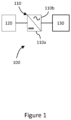
- FIG 1 is a schematic illustration of an example DC transmission system node 100 including a power converter 110 connected between a DC source 120 and an AC grid 130.
- the illustration is not intended to be limited to representing a particular interconnect, but is moreover provided as a generic example illustrating principles of operation of an interconnect that are useful for understanding the invention.
- specific features in the illustration are shown connected to each other with a specific number of connections, it will be understood that this is not intended to be limiting either, but moreover to illustrate a generic connection between features/components.
- relative dimensions or distances between components perceived in the illustration are also not intended to be limiting. It will therefore be understood that principles and features in the DC transmission system node 100 and herein discussed can be applied to interconnects comprising the controller 200 shown in Figure 2 , or power converters or networks operated using the controller 200.
- the DC transmission system node 100 comprises a first inverter-based resource 110 (also known as a power converter 110).
- the power converter 110 is configured to convert DC power to AC power, acting essentially as an inverter, or to convert AC power to DC power, acting as a rectifier. In other words, the power converter 110 can perform bi-directional power conversion.
- the power converter 110 may comprise a single converter in the case of a monopole system, or two converters in the case of a bipole system.
- the power converter 110 may represent a plurality of converter stations arranged as a multi-terminal power transmission system. In this example, the power converter 110 comprises a DC side 110a and an AC side 110b.
- the power converter 110 is connected to the DC source 120.
- the DC source 120 is connected to the DC side 110a of the power converter 110.
- the power converter 110 is connected to the AC grid 130.
- the AC grid 130 is connected to the AC side 110b of the power converter 110.
- the DC source 120 and/or the AC grid 130 may be electrical power transmission systems comprising power generation apparatus, transmission apparatus, distribution apparatus, and electrical loads.
- the DC source 120 may be part of a HVDC transmission system.
- the AC grid 130 may be a consumer network.
- the DC source 120 is part of a HVDC transmission system, with the AC grid 130 being a consumer network, for instance.
- the AC grid 130 can be of any size and, due to operational factors, can have changing electrical characteristics.
- the AC grid 130 can have a ⁇ strength' characteristic, which may be as defined, from an impedance point of view, in CIGRE TB 68, " Guide for Planning DC Links Terminating at AC Systems Locations having Low Short-Circuit Capabilities; Part 1: ACDC Interaction Phenomena", June 1992 .
- the 'strength' of an AC system may be determined by the ratio of the AC system short circuit capacity to DC link power (also known as ⁇ short circuit ratio', SCR).
- a 'weaker' system may have a lower ratio of AC system short circuit capacity to DC link power, for instance an SCR value of less than 2.
- a 'stronger' system may have a higher ratio of AC system short circuit capacity to DC link power, for instance a SCR value of greater than 3.
- a strong AC system may have a low amount of impedance between a DC source and the AC system
- a weak AC system may have a high amount of impedance between a DC source and the AC system.
- the AC grid 130 can be a weak AC system or a strong AC system, or can change from a weak system to a strong system during operation of the AC grid 130, or vice versa.
- a change in the strength of the AC grid 130 may happen a result of changes in the AC grid 130, for example the disconnection or connection of a high impedance load.
- the strength of the AC grid 130 may, and in practice will, change during operation of the AC grid 130. It is therefore desirable for the power converter 110 to operate in a manner that supports the AC grid 130 regardless of whether the AC grid 130 is a strong AC system or a weak AC system.
- the operation of the DC transmission system node 100 can be generically described as follows.
- the DC power source 120 either provides or consumes DC power to or from the power converter 110 at the DC side 110a.
- the power converter 110 converts the received DC power to AC power for the AC grid 130, thereby acting as an inverter.
- the power converter 110 converts received AC power from the AC grid 130 to DC power, to be absorbed by the DC power source 120, thereby acting as a rectifier.
- the DC power source 120 provides power to the power converter 110
- the AC power output from the power converter 110 is transmitted from the AC side 110b to the AC grid 130 for consumption, for instance.
- DC transmission system node 100 may include switches, transformers, resistors, reactors, surge arrestors, harmonic filters and other components well known in the art.
- converters or power conversion means may comprise a number of different technologies such as voltage sourced converters (for instance using insulated gate bipolar transistor (IGBT) valves). Such converters may generally be considered to use ⁇ power electronics'.
- Power electronic converters may comprise multilevel voltage sourced converters, for instance.
- cables used as power transmission mediums may comprise the following non-limiting examples of crosslinked polyethylene (XLPE) and/or mass impregnated (MI) insulation cables.
- XLPE crosslinked polyethylene
- MI mass impregnated
- Such cables may comprise a conductor (such as copper or aluminium) surrounded by a layer of insulation.
- Dimensions of cables and their associated layers may be varied according to the specific application (and in particular, operational voltage requirements). Cables may further comprise strengthening or 'armouring' in applications such as subsea installation. Cables may further comprise sheaths/screens that are earthed at one or more locations.
- the DC transmission system node 100 may be used with three-phase power systems.
- three conductors supply respective first, second and third phases of AC power to a consumer.
- FIG 2 is a schematic illustration showing an embodiment of a controller 200 as may be used in implementing the methods described herein, in order to control the power converter 110 shown in Figure 1 to operate in a grid-forming mode.
- the controller 200 comprises an adjustment module 210, a feedforward module 220, a control module 230, a first transformation module 250, a summing component 260, and a second transformation module 270. Additionally, the controller 200 receives a power demand P demand , a measured power P meas , and a measured frequency f g , each of which are discussed further below.
- the power demand P demand is a demand for an amount of power to be output from the power converter 110.
- the measured power P meas is an amount of power output from the power converter 110.
- the measured frequency f g is a measure of a frequency component of the AC grid 130.
- the power demand P demand , the measured power P meas and measured frequency f g are provided to the control module 230.
- the control module 230 performs processing and outputs a first control signal 240 to the summing component 260.
- the power demand P demand is provided to the feedforward module 220.
- the feedforward module 220 receives the power demand P demand and an adjustment value X k , performs processing, and outputs a feedforward signal ⁇ 1.
- the feedforward module 220 outputs the feedforward signal ⁇ 1 to the adjustment module 210.
- the measured power P meas is also provided to the adjustment module 210.
- the adjustment module 210 receives the measured power P meas and the feedforward signal ⁇ 1, performs processing, and outputs the adjustment value X k .
- the adjustment value X k is provided to the feedforward module 220. In this manner, the feedforward module 220 and the adjustment module 210 form a first closed-loop control system 225.
- the feedforward module 220 also outputs the feedforward signal ⁇ 1 to the first transformation module 250.
- the first transformation module 250 receives the feedforward signal ⁇ 1, performs processing, and outputs a transformed feedforward signal 255 to the summing component 260.
- the summing component 260 sums the transformed feedforward signal 255 and the first control signal 240, and outputs the result as a second control signal ⁇ to the second transformation module 270.
- the second transformation module 270 receives the second control signal ⁇ , performs processing, and outputs a phase angle command ⁇ for providing grid-forming control to the power converter 110.
- the controller 200 may comprise a memory and at least one processor.
- the memory may comprise computer-readable instructions, which when executed by the at least one processor, cause the controller 200 to perform the method(s) described herein.
- the controller 200 may further comprise a transceiver apparatus.
- the transceiver apparatus may comprise a separate transmitter and receiver.
- the transceiver apparatus may be used to operatively communicate with other components described herein either directly, using a wired or wireless means, or via a further interface such as a network interface.
- the transceiver apparatus may for instance send and receive control signals using the transmitter and receiver.
- the control signals may contain or define electrical control parameters such as reference currents or reference voltages.
- the at least one processor may be capable of executing computer-readable instructions and/or performing logical operations.
- the at least one processor may be a microcontroller, microprocessor, central processing unit (CPU), field programmable gate array (FPGA) or similar programmable controller.
- the controller 200 may further comprise a user input device and/or output device.
- the processor may be communicatively coupled to the memory and to the transceiver.
- the memory may be a computer readable storage medium.
- the memory may include a non-volatile computer storage medium.
- the memory may include a hard disk drive, flash memory, etc.
- the controller 200 may additionally include a user input device interface and/or a user output device interface, which may allow for visual, audible or haptic inputs/outputs.
- user input/output devices include, but are not limited to, interfaces to electronic displays, touchscreens, keyboards, mice, speakers and microphones.
- the power converter 110 is operating a GFM mode. Aspects of the disclosure provide improvements when the power converter 110 is operating in a GFM mode, as will now be discussed.
- control module 230 of the controller 200 implements a second closed-loop control system 237 which includes an integral function 235.
- a power demand P demand is provided to the control module 230 and the measured power P meas is closely matched, or is the same as, the power demand P demand .
- the power demand P demand is a demand for an amount of power to be output from the power converter 110.
- the measured power P meas is an amount of power output from the power converter 110.
- the control module 230 will detect the change in the measured power P meas and the measured frequency f g .
- the measured frequency f g is a measure of a frequency component of the AC grid 130.
- the second closed-loop control system 237 in the control module 230 determines a first control signal 240, which will maintain an internal voltage vector of the power converter 110.
- the active power flow between the power converter 110 and the AC grid 130 will, therefore, rapidly change because of an angular difference between the power converter 110 and the AC grid 130.
- the new power flow is only intended to be temporary and hence the (synchronous grid-forming) controller 200 will modify its internal voltage vector to restore the pre-disturbance conditions or a modified steady-state based on the new AC grid 130 frequency if the controller 200 incorporates a frequency droop function.
- the time-period over which this modification will be achieved will be a parameter defined by the integral function 235.
- a limitation of the control module 230 is that it may have a poor ability to track a change in the power demand P demand . This problem is addressed by conventional controllers by circumventing the slow inertial response of the control module 230 (which arises as a result of the integral function 235), to directly modify the phase angle command ⁇ of the power converter 110 as a function of the power demand P demand applied to the power converter 110.
- the basic concept is based on the transfer equation shown below as Equation 1.
- P demand V cnv ⁇ V thev ⁇ sin ⁇ Vcnv ⁇ ⁇ Vthev X cnv + X thev
- P demand is a demand for an amount of power to be output from the power converter 110:
- V cnv is the output voltage of the power converter 110;
- V thev is the Thévenin equivalent voltage of the AC grid 130;
- ⁇ cnv is the angle of the power converter 110 output voltage;
- ⁇ thev is the angle of the Thévenin equivalent AC grid 130 voltage;
- X cnv is the power converter 130 impedance;
- X thev is the Thévenin equivalent impedance of the AC grid 130.
- V t is a voltage at the power converter 110 point of connection to the AC grid 130; and ⁇ t is the angle of the voltage at the power converter point of connection to the AC grid 130.
- Equation 2 tends to be more practical, as the quantities V t and ⁇ t are directly measurable at the power converter 110. A further simplification can be made if it is assumed that V cnv and V t are, in the steady-state condition, both equal to 1.0 pu.
- the feedforward module 220 and the resultant feedforward signal ⁇ 1, as shown in Figure 2 are thus an implementation of a feedforward term based on a re-arranged Equation 2. Furthermore, an additional simplification can be made, noting that, typically the AC grid 130 voltage will be near 1.0pu. Hence, if required, for example to improve computation time, it can be assumed that V t and V cnv are equal to 1.0.
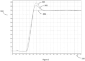
- Figure 3 shows a first plot 301 of the power demand P demand to the power converter 110, a second plot 302 of the measured power P meas output from the power converter 110 with the feedforward module 220 active, and a third plot 303 of the measured power P meas output from the power converter 110 both with the feedforward module 220 not active.
- the x-axis 320 is time in seconds and the y-axis 310 is power in per unit.
- a power converter 110 controlled with the feedforward module 220 tends to actively track changes in the power demand P demand better than a power converter 110 controlled without the feedforward module 220 active.
- the feedforward module 220 and the resultant feedforward signal ⁇ 1 can also be used to accelerate a recovery of the power converter 110 following a clearance of a fault on the AC grid 130 (i.e., the time taken to restore the power demand P demand).
- the feedforward module 220 outputs the feedforward signal 61 to the first transformation module 250, which applies a transformation, for example a Laplace transform, to the feedforward signal 61.
- the transformation transforms the feedforward signal ⁇ 1 from an angle to a rotational speed, and the output is a transformed feedforward signal 255, which the first transformation module 250 provides to the summing component 260.
- the summing component 260 sums the first control signal 240 and the transformed feedforward signal 255. By summing the first control signal 240 and the transformed feedforward signal 255. In this manner, the signal with the larger magnitude can, and in practice will, dominate the phase angle command ⁇ . This tends to allow the controller 200 to track changes in the power demand as well as power changes in the grid.
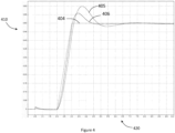
- Figure 4 shows a fourth plot 404 of a power demand P demand provided to a power converter 110, a fifth plot 405 of a measured power P meas output from the power converter 110 (with the feedforward module 220 active) for a weak AC system, and a sixth plot 406 of a measured power P meas output from the power converter 110 (with the feedforward module 220 active) for a strong AC system.
- the x-axis 420 is time in seconds and the y-axis 410 is power in per unit.
- the feedforward module 220 and the resultant feedforward signal 61 fail to track a ramp or change in the power demand P demand effectively.
- the controller 200 comprises the adjustment module 210.
- a general operating principle of the adjustment module 210 is that the adjustment module 210 makes a correction for an error between an expected power demand P demand and the measured power P meas , to improve the active power ramp tracking.
- the adjustment module 210 in the controller 200 uses the measured power P meas , and from this, by manipulating Equation 2, an adjustment value X k can be derived as shown in Equation 3.
- X k V cnv ⁇ V t ⁇ sin ⁇ 1 P meas ⁇ X cnv
- the adjustment module 210 thus implements Equation 3, rearranged to resolve for the adjustment value X k . However, as can be seen, in order to fully implement Equation 3, a value for the feedforward signal ⁇ 1 must be determined. The adjustment module 210 thus receives a value for the feedforward signal ⁇ 1 from the feedforward module 220.
- Equation 3 the adjustment module 210 implements rearranged Equation 3
- other formulae may also be used in other embodiments.
- the choice of formula may, for example, be selected based upon a particular type of application.
- the feedforward module 220 In order for the feedforward signal ⁇ 1 to configure the power converter 110 to track a ramp in a power demand P demand effectively, the feedforward module 220 must also be updated to take into account the adjustment value X k .
- Equation 2 An adaptation of Equation 2 can then be used to incorporate the resultant from Equation 3, as shown in Equation 4.
- P demand V cnv ⁇ V t ⁇ sin ⁇ 1 X cnv + X k
- the feedforward module 220 of the disclosure implements Equation 4, rearranged to resolve for the feedforward signal ⁇ 1. And, as can be seen, the adjustment value X k is needed to solve the equation fully.
- the adjustment value X k is provided to the feedforward module 220 by the adjustment module 210.
- the adjustment module 210 and the feedforward module 220 form a first closed-loop control system 225.
- the feedforward signal ⁇ 1 is thus automatically adjusted to compensate for differences in the power demand and the measured power during a change in the power demand.
- a reference value for the adjustment value X k and the feedforward signal 61 may be used.
- feedforward module 220 implements rearranged Equation 4
- other formulae may also be used in other embodiments.
- the choice of formula may, for example, be selected based upon a particular type of application.
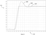
- Figure 5 shows a seventh plot 507 of a power demand P demand provided to a power converter 110 connected to a weak grid, an eight plot 508 of a measured power P meas with the adjustment module 210 enabled to provide the adjustment value X k , and a ninth plot 509 of a measured power P meas with the adjustment module 210 disabled.
- the x-axis 520 is time in seconds and the y-axis 510 is power in per unit.
- the measured power P meas tracks the power demand P demand considerably better compared to when the adjustment module 210 is disabled.
- the phase angle command ⁇ provided to the power converter 110 tends to improve the capability of the power converter 110 to output power (the measured power P meas ) that tracks the power demand P demand closely and accurately. In other words, the power converter 110 is more effective in providing the desired output power when operating in a grid-forming mode.
- the adjustment module 210 may cause a further problem if the AC system is too weak, and the power converter 110 recovers the active power too quickly. Therefore, in an embodiment of this disclosure, the adjustment module 210 can be automatically disabled, if the adjustment value X k would cause the power converter 110 to operate in a manner that would have an undesirable impact on the AC grid 130.
- a comparator 280 may be included in the controller 200.
- the comparator 280 is connected to the output of the adjustment module 210, at a point between the adjustment module 210 and the feedforward module 220. As a result, the comparator 280 is able to modify the adjustment value X k if required.
- the comparator 280 receives the adjustment value X k , compares the adjustment value X k to a threshold value, and outputs the result to the feedforward module 220. If the adjustment value is equal to or below the threshold value, then the comparator 280 forwards the adjustment value X k , determined by the adjustment module 210, to the feedforward module 220, and thereby enables the adjustment module 210. However, if the adjustment value X k is above the threshold value, then the comparator 280 updates the adjustment value X k to a reference value or to zero, and forwards the updated adjustment value to the feedforward module 220, and thereby disables the adjustment module 210. In this manner, the adjustment module 210 may be enabled or disabled.
- the enabling or disabling of the adjustment module 210 is further determined based on a hysteresis, such that the adjustment module 210 is disabled if the adjustment value Xk is above a second threshold value, and the adjustment module 210 is enabled if the adjustment value Xk is equal to or below a third threshold.
- a list with a conjunction of "and/or” includes any single item in the list or a combination of items in the list.
- a list of A, B and/or C includes only A, only B, only C, a combination of A and B, a combination of B and C, a combination of A and C or a combination of A, B and C.
- a list using the terminology "one or more of” includes any single item in the list or a combination of items in the list.
- one or more of A, B and C includes only A, only B, only C, a combination of A and B, a combination ofB and C, a combination of A and C or a combination of A, B and C.
- a list using the terminology “one of” includes one, and only one, of any single item in the list.
- “one of A, B and C” includes only A, only B or only C and excludes combinations of A, B and C.
- a member selected from the group consisting of A, B, and C includes one and only one of A, B, or C, and excludes combinations of A, B, and C.”
- "a member selected from the group consisting of A, B, and C and combinations thereof' includes only A, only B, only C, a combination of A and B, a combination of B and C, a combination of A and C or a combination of A, B and C.
- each block in the schematic flowchart diagrams and/or schematic block diagrams may represent a module, segment, or portion of code, which includes one or more executable instructions of the code for implementing the specified logical function(s).
- the disclosure herein also provides a converter controller that is operating in a synchronous grid forming mode, that is, the controller is controlling the converters AC voltage vector in phase and magnitude instantaneously independent of the phase and magnitude of the AC system as measured at the converters point of connection to the AC system.
- the converter automatically adjusts its voltage phase and magnitude to compensate for differences between a user demanded value, either active power or DC voltage, and the actual measured value to give an inertial response defined in a way that provides a decaying demand value violation and where the decay time is a user defined parameter.
- This converter further includes a feed-forward term which modifies the inertial response of the converter to better track actual demand quantity changes, as opposed to sudden network events.
- the feed-forward term can automatically adjust the change it makes to the converter voltage phase to compensate for differences between the desired value and the measured value at any instance in time during the change in the demand value.
- the correction factor can be automatically disabled based on the magnitude of the correction factor.
- the correction factor can be automatically enabled based on the magnitude of the correction factor.
Landscapes
- Engineering & Computer Science (AREA)
- Power Engineering (AREA)
- Supply And Distribution Of Alternating Current (AREA)
Abstract
Description
- The subject matter herein relates generally to the field of power transmission networks and more specifically to a method of operating a controller, and a controller, for providing grid-forming control of a power converter connected to a grid.
- In high voltage direct current (HVDC) power transmission networks, alternating current (AC) power is typically converted to direct current (DC) power for transmission via overhead lines, under-sea cables and/or underground cables. This conversion removes the need to compensate for the AC reactive/capacitive load effects imposed by the power transmission medium, i.e., the transmission line or cable, and reduces the cost per kilometer of the lines and/or cables, and thus becomes cost-effective when power needs to be transmitted over a long distance. DC power can also be transmitted directly from offshore wind parks to onshore AC power transmission networks, for instance.
- The conversion between DC power and AC power is utilized where it is necessary to interconnect DC and AC networks. In any such power transmission network, power conversion means, also known as converters (i.e., power converters in converter stations), are required at each interface between AC and DC power to effect the required conversion from AC to DC or from DC to AC.
- When converting DC power to AC power, for example, at an interface between a DC transmission line and an AC grid, a power converter may be operated in a grid-following mode (GFL) or a grid-forming mode (GFM).
- In the GFL mode, the power converter utilizes fast current-regulation loops to control active and reactive power exchanged with the AC grid. The power converter uses a current reference from the AC grid for the active component of current to achieve a desired power output. Accordingly, a power converter operating in a GFL mode includes functions that manage the voltage and reactive power in a manner that results in a command for the reactive component of current. Wide-bandwidth current regulators then develop commands for voltage to be applied by the power converter to the AC grid, such that the actual currents closely track the commands. A power converter operating in a GFL mode therefore provides a current-source characteristic.
- Alternatively, a power converter operating in a GFM mode provides a voltage-source characteristic, where the phase angle and magnitude of the voltage are controlled to achieve the regulation functions demanded by the grid. With this structure, current will flow according to the demands of the grid while the converter contributes to establishing a voltage and frequency for the grid. This characteristic is comparable to conventional generators based on a turbine driving a synchronous machine.
- To be effective, grid-forming resources should be able to maintain an internal voltage phasor that does not move quickly when there are changes in grid conditions, e.g. sudden addition/removal of loads, opening or closing of grid connections that lead to phase jumps and/or rapid change of frequency. In other words, the power from the power converter should be able to change suddenly to stabilize the grid, with a subsequent slow reset to power being commanded from a higher-level control function. In addition, the grid forming resource should be able to rapidly enforce power limits that exist due to constraints on the power-handling portions of the device, e.g. DC voltages/currents in a battery, solar array, and/or wind generating system. Such a response is preferable for mitigating severe disturbances on the grid, e.g. faults where power limits will be dynamically adjusted to coordinate with grid conditions for secure recovery from the fault. Further, the grid forming resource should be able to rapidly follow changes in commands from higher-level controls, e.g. for damping mechanical vibrations in a wind turbine.
- In certain conventional systems, the aforementioned issues may be solved by determining a feedforward signal as a function of one or more power demands, one or more control signals, and one or more estimated electrical conditions of an inverter-based resource, and using the feedforward signal to position at least one control angle of the inverter-based resource to an anticipated value needed to achieve the one or more reference commands, thereby enabling rapid response to the one or more reference commands received from the external controller.
- The present inventors have realised that, to be even more effective, the feedforward term should accurately track changes in the power demand, regardless of the electrical characteristics of the AC grid (for example an impedance of the AC grid). There thus remains scope in providing improvements to grid-forming control of a power converter in power transmission networks.
- According to a first aspect, there is provided a method of operating a controller for providing grid-forming control of a power converter connected to a grid, the method comprising determining, by an adjustment module of the controller, an adjustment value based on a measured power and a feedforward signal, wherein the measured power is indicative of an amount of power output from the power converter; determining, by a feedforward module of the controller, the feedforward signal based on a power demand and the adjustment value, wherein the power demand is indicative of a demand for an amount of power to be output from the power converter; wherein the adjustment module and the feedforward module form a first closed-loop control system to determine the feedforward signal, such that the feedforward signal is automatically adjusted to compensate for differences in the power demand and the measured power during a change in the power demand; and determining, by the controller, a phase angle command for the power converter based on the feedforward signal.
- Because the adjustment module and the feedforward module form a closed-loop control system to determine the feedforward signal, the phase angle command provided to the power converter tends to improve the capability of the power converter to output power (the measured power) that tracks changes in the power demand closely and accurately. In other words, the power converter tends to be more effective in providing the desired changes in output power when operating in a grid-forming mode.
- In some embodiments, the method further comprises determining, by a control module in the controller, a first control signal, based on the power demand, the measured power, and a measured frequency, wherein the measured frequency is a measure of a frequency component of the AC grid; and determining, by the controller, the phase angle command for the power converter based on the feedforward signal and the first control signal.
- In some embodiments the method further comprises transforming, by a first transformation module of the controller, the feedforward signal, and outputting a transformed feedforward signal; summing, by a summing component of the controller, the first control signal with the transformed feedforward signal, and outputting a second control signal; and determining, by the controller, the phase angle command based on the second control signal, such that the power converter is able to track changes in the power demand as well as power changes in the AC grid.
- By using the feedforward signal and the first control signal to determine the phase angle command, the power converter tends to be able to respond effectively to changes in the power demand and changes in the AC grid.
- In some embodiments, the method further comprises determining, by a second transformation module of the controller, the phase angle command by transforming the second control signal, and outputting the phase angle command to the power converter.
- In some embodiments, the control module comprises a second closed-loop control system including an integral term.
- In some embodiments, the adjustment module implements an equation comprising: multiplying a grid voltage with a power converter voltage and the sine of the feedforward signal to determine a first product, and then dividing the first product by the measured power; wherein the grid voltage is indicative of a voltage at a connection point between the power converter and the grid, and the power converter voltage is indicative of an output voltage of the power converter.
- In some embodiments, the feedforward module implements an equation comprising summing a converter impedance with the adjustment value to determine a third product; multiplying the third product by the power demand to determine a fourth product; multiplying the power converter voltage by a grid voltage (Vt) to determine a fifth product; dividing the fourth product by the fifth product to determine a sixth product; and determining the arcsine of the sixth product; wherein the grid voltage is indicative of a voltage at a connection point between the power converter and the grid, and the power converter voltage is indicative of an output voltage of the power converter.
- In some embodiments, the method further comprises comparing, by a comparator in the controller, the adjustment value with a threshold value.
- In some embodiments, the method further comprises enabling or disabling the adjustment module based on the comparison.
- In some embodiments, the enabling or disabling the adjustment module is done by the controller.
- In some embodiments, the enabling or disabling the adjustment module is done by the comparator in the controller.
- In some embodiments, if the adjustment value is equal to or below the first threshold value, then the comparator forwards the adjustment value, determined by the adjustment module, to the feedforward module, and thereby enables the adjustment module.
- In some embodiments, if the adjustment value is above the first threshold value, then the comparator updates the adjustment value to a reference value or to zero, and forwards the updated adjustment value to the feedforward module, and thereby disables the adjustment module.
- In some embodiments the enabling or disabling of the adjustment module is further determined based on a hysteresis, such that the adjustment module is disabled if the adjustment value is above a second threshold value, and the adjustment module is enabled if the adjustment value is equal to or below a third threshold.
- According to a second aspect, there is provided a controller providing grid-forming control of a power converter connected to a grid, the controller comprising an adjustment module configured to determine an adjustment value based on a measured power and a feedforward signal, wherein the measured power is indicative of the amount of power output from the power converter; and a feedforward module configured to determine the feedforward signal based on a power demand and the adjustment value, wherein the power demand is indicative of a demand for an amount of power to be output from the power converter; wherein the adjustment module and the feedforward module form a first closed-loop control system configured to determine the feedforward signal, such that the feedforward signal is automatically adjusted to compensate for differences between the power demand and the measured power during a change in the power demand; and the controller is further configured to determine a phase angle command for the power converter based on the feedforward signal.
- Generally, the controller tends to be configured to execute the methods described herein.
- In some embodiments, the controller further comprises a control module configured to determine a first control signal, based on the power demand, the measured power, and a measured frequency, wherein the measured frequency is a measure of a frequency component of the AC grid; and a first transformation module configured to transform the feedforward signal to a transformed feedforward signal; wherein the controller is further configured to sum the first control signal with the transformed feedforward signal to output a second control signal, and determine the phase angle command based on the second control signal, such that the power converter is able to track changes in the power demand as well as power changes in the AC grid.
- In some embodiments, the controller further comprises a comparator configured to compare the adjustment value with a threshold value; wherein if the adjustment value is equal to or below the threshold value, then the comparator is configured to forward the adjustment value, determined by the adjustment module, to the feedforward module, and thereby enable the adjustment module; and wherein if the adjustment value is above the threshold value, then the comparator is configured to update the adjustment value to a reference value or to zero, and forward the updated adjustment value to the feedforward module, and thereby disable the adjustment module.
- According to a third aspect, there is provided a power converter comprising a DC side for connection to a DC source; an AC side for connection to an AC grid; and the controller of the second aspect.
- In some embodiments, the AC grid is one or more of: a consumer network; an islanded generation network; or an islanded load.
- In some embodiments, the DC source is a HVDC transmission system.
- According to a fourth aspect, there is provided a computer program comprising instructions which when executed by a processor of a controller for controlling a power converter, cause the controller to perform the method of the first aspect.
- According to a fifth aspect, there is provided a non-transitory computer-readable storage medium comprising the computer program of the fourth aspect.
- It will be appreciated that particular features of different aspects of the invention share the technical effects and benefits of corresponding features of other aspects of the invention. More specifically, the controller, the power converter, the computer program, and the non-transitory computer-readable medium, share the technical effects and benefits of the method of the invention.
- It will also be appreciated that the use of the terms "first" and "second", and the like, are merely intended to help distinguish between similar features and are not intended to indicate a relative importance of one feature over another, unless otherwise specified.
- Within the scope of this application, it is expressly intended that the various aspects, embodiments, examples and alternatives set out in the preceding paragraphs, and the claims and/or the following description and drawings, and in particular the individual features thereof, may be taken independently or in any combination. That is, all embodiments and all features of any embodiment can be combined in any way and/or combination, unless such features are incompatible.
- Embodiments of the invention will now be described by way of example only and with reference to the accompanying drawings, in which:
-
Figure 1 is a schematic illustration of an example of a power converter connected between a DC source and an AC grid; -
Figure 2 is a schematic illustration of a controller; -
Figure 3 is a graph showing a power demand, and the power output from a converter operated with and without a feedforward term; -
Figure 4 is a graph showing a power demand, and a converter power output for a strong AC system and a weak AC system; -
Figure 5 is a graph showing a power demand to a power converter connected to a weak AC grid, and the power output from the power converter when operated according to a conventional method, and the power output from the power converter when operated according to the method disclosed herein. -
Figure 1 is a schematic illustration of an example DCtransmission system node 100 including apower converter 110 connected between aDC source 120 and anAC grid 130. The illustration is not intended to be limited to representing a particular interconnect, but is moreover provided as a generic example illustrating principles of operation of an interconnect that are useful for understanding the invention. Hence whilst specific features in the illustration are shown connected to each other with a specific number of connections, it will be understood that this is not intended to be limiting either, but moreover to illustrate a generic connection between features/components. Related, is that relative dimensions or distances between components perceived in the illustration are also not intended to be limiting. It will therefore be understood that principles and features in the DCtransmission system node 100 and herein discussed can be applied to interconnects comprising the controller 200 shown inFigure 2 , or power converters or networks operated using the controller 200. - The DC
transmission system node 100 comprises a first inverter-based resource 110 (also known as a power converter 110). Thepower converter 110 is configured to convert DC power to AC power, acting essentially as an inverter, or to convert AC power to DC power, acting as a rectifier. In other words, thepower converter 110 can perform bi-directional power conversion. Thepower converter 110 may comprise a single converter in the case of a monopole system, or two converters in the case of a bipole system. Thepower converter 110 may represent a plurality of converter stations arranged as a multi-terminal power transmission system. In this example, thepower converter 110 comprises aDC side 110a and anAC side 110b. - The
power converter 110 is connected to theDC source 120. TheDC source 120 is connected to theDC side 110a of thepower converter 110. - The
power converter 110 is connected to theAC grid 130. TheAC grid 130 is connected to theAC side 110b of thepower converter 110. - The
DC source 120 and/or theAC grid 130 may be electrical power transmission systems comprising power generation apparatus, transmission apparatus, distribution apparatus, and electrical loads. TheDC source 120 may be part of a HVDC transmission system. TheAC grid 130 may be a consumer network. By way of non-limiting example, theDC source 120 is part of a HVDC transmission system, with theAC grid 130 being a consumer network, for instance. - The
AC grid 130 can be of any size and, due to operational factors, can have changing electrical characteristics. In particular, theAC grid 130 can have a `strength' characteristic, which may be as defined, from an impedance point of view, in CIGRE TB 68, "Guide for Planning DC Links Terminating at AC Systems Locations having Low Short-Circuit Capabilities; Part 1: ACDC Interaction Phenomena", June 1992. The 'strength' of an AC system may be determined by the ratio of the AC system short circuit capacity to DC link power (also known as `short circuit ratio', SCR). A 'weaker' system may have a lower ratio of AC system short circuit capacity to DC link power, for instance an SCR value of less than 2. A 'stronger' system may have a higher ratio of AC system short circuit capacity to DC link power, for instance a SCR value of greater than 3. In other words, a strong AC system may have a low amount of impedance between a DC source and the AC system, whereas a weak AC system may have a high amount of impedance between a DC source and the AC system. These definitions, as are known in the art to the skilled person, are used herein when referring to a weak AC system and a strong AC system. - In the example disclosed in
Figure 1 , theAC grid 130 can be a weak AC system or a strong AC system, or can change from a weak system to a strong system during operation of theAC grid 130, or vice versa. A change in the strength of theAC grid 130 may happen a result of changes in theAC grid 130, for example the disconnection or connection of a high impedance load. Because there is no limitation of the size of theAC grid 130, the strength of theAC grid 130 may, and in practice will, change during operation of theAC grid 130. It is therefore desirable for thepower converter 110 to operate in a manner that supports theAC grid 130 regardless of whether theAC grid 130 is a strong AC system or a weak AC system. - The operation of the DC
transmission system node 100 can be generically described as follows. TheDC power source 120 either provides or consumes DC power to or from thepower converter 110 at theDC side 110a. Thepower converter 110 converts the received DC power to AC power for theAC grid 130, thereby acting as an inverter. Alternatively, thepower converter 110 converts received AC power from theAC grid 130 to DC power, to be absorbed by theDC power source 120, thereby acting as a rectifier. Following the example that theDC power source 120 provides power to thepower converter 110, the AC power output from thepower converter 110 is transmitted from theAC side 110b to theAC grid 130 for consumption, for instance. - It will be appreciated that various other electrical components may be located at any particular location or with any particular feature/component in the example DC
transmission system node 100. These may include switches, transformers, resistors, reactors, surge arrestors, harmonic filters and other components well known in the art. - It will be appreciated that converters or power conversion means may comprise a number of different technologies such as voltage sourced converters (for instance using insulated gate bipolar transistor (IGBT) valves). Such converters may generally be considered to use `power electronics'. Power electronic converters may comprise multilevel voltage sourced converters, for instance.
- It will be appreciated that cables used as power transmission mediums may comprise the following non-limiting examples of crosslinked polyethylene (XLPE) and/or mass impregnated (MI) insulation cables. Such cables may comprise a conductor (such as copper or aluminium) surrounded by a layer of insulation. Dimensions of cables and their associated layers may be varied according to the specific application (and in particular, operational voltage requirements). Cables may further comprise strengthening or 'armouring' in applications such as subsea installation. Cables may further comprise sheaths/screens that are earthed at one or more locations.
- Moreover, it will be understood that the DC
transmission system node 100 may be used with three-phase power systems. In a three-phase power system, three conductors supply respective first, second and third phases of AC power to a consumer. -
Figure 2 is a schematic illustration showing an embodiment of a controller 200 as may be used in implementing the methods described herein, in order to control thepower converter 110 shown inFigure 1 to operate in a grid-forming mode. - As shown in
Figure 2 , the controller 200 comprises anadjustment module 210, afeedforward module 220, acontrol module 230, afirst transformation module 250, a summingcomponent 260, and asecond transformation module 270. Additionally, the controller 200 receives a power demand P demand, a measured power P meas, and a measured frequency fg , each of which are discussed further below. - The power demand P demand is a demand for an amount of power to be output from the
power converter 110. The measured power P meas is an amount of power output from thepower converter 110. The measured frequency fg is a measure of a frequency component of theAC grid 130. The power demand P demand, the measured power P meas and measured frequency fg are provided to thecontrol module 230. Thecontrol module 230 performs processing and outputs afirst control signal 240 to the summingcomponent 260. - The power demand P demand is provided to the
feedforward module 220. Thefeedforward module 220 receives the power demand P demand and an adjustment value Xk, performs processing, and outputs a feedforward signal δ1. - The
feedforward module 220 outputs the feedforward signal δ1 to theadjustment module 210. The measured power P meas is also provided to theadjustment module 210. Theadjustment module 210 receives the measured power P meas and the feedforward signal δ1, performs processing, and outputs the adjustment value Xk. The adjustment value Xk is provided to thefeedforward module 220. In this manner, thefeedforward module 220 and theadjustment module 210 form a first closed-loop control system 225. - The
feedforward module 220 also outputs the feedforward signal δ1 to thefirst transformation module 250. Thefirst transformation module 250 receives the feedforward signal δ1, performs processing, and outputs a transformedfeedforward signal 255 to the summingcomponent 260. - The summing
component 260 sums the transformedfeedforward signal 255 and thefirst control signal 240, and outputs the result as a second control signal Δω to thesecond transformation module 270. - The
second transformation module 270 receives the second control signal Δω, performs processing, and outputs a phase angle command δ for providing grid-forming control to thepower converter 110. - Although not shown in
Figure 2 , the controller 200 may comprise a memory and at least one processor. The memory may comprise computer-readable instructions, which when executed by the at least one processor, cause the controller 200 to perform the method(s) described herein. - Also, although not shown in
Figure 2 , the controller 200 may further comprise a transceiver apparatus. The transceiver apparatus may comprise a separate transmitter and receiver. The transceiver apparatus may be used to operatively communicate with other components described herein either directly, using a wired or wireless means, or via a further interface such as a network interface. The transceiver apparatus may for instance send and receive control signals using the transmitter and receiver. The control signals may contain or define electrical control parameters such as reference currents or reference voltages. - The at least one processor may be capable of executing computer-readable instructions and/or performing logical operations. The at least one processor may be a microcontroller, microprocessor, central processing unit (CPU), field programmable gate array (FPGA) or similar programmable controller. The controller 200 may further comprise a user input device and/or output device. The processor may be communicatively coupled to the memory and to the transceiver.
- The memory may be a computer readable storage medium. For instance, the memory may include a non-volatile computer storage medium. For example, the memory may include a hard disk drive, flash memory, etc.
- Also, although not shown in
Figure 2 , the controller 200 may additionally include a user input device interface and/or a user output device interface, which may allow for visual, audible or haptic inputs/outputs. Examples of such user input/output devices include, but are not limited to, interfaces to electronic displays, touchscreens, keyboards, mice, speakers and microphones. - As discussed above, in the example disclosed, the
power converter 110 is operating a GFM mode. Aspects of the disclosure provide improvements when thepower converter 110 is operating in a GFM mode, as will now be discussed. - In order to achieve grid-forming control, the
control module 230 of the controller 200 implements a second closed-loop control system 237 which includes anintegral function 235. During a steady-state condition, a power demand P demand is provided to thecontrol module 230 and the measured power P meas is closely matched, or is the same as, the power demand P demand. - The power demand P demand is a demand for an amount of power to be output from the
power converter 110. The measured power P meas is an amount of power output from thepower converter 110. - If a voltage vector of the
AC grid 130 changes because of, for example, anAC grid 130 load switch event or generator switch, thecontrol module 230 will detect the change in the measured power P meas and the measured frequency fg. The measured frequency fg is a measure of a frequency component of theAC grid 130. - The second closed-
loop control system 237 in thecontrol module 230 determines afirst control signal 240, which will maintain an internal voltage vector of thepower converter 110. The active power flow between thepower converter 110 and theAC grid 130 will, therefore, rapidly change because of an angular difference between thepower converter 110 and theAC grid 130. The new power flow is only intended to be temporary and hence the (synchronous grid-forming) controller 200 will modify its internal voltage vector to restore the pre-disturbance conditions or a modified steady-state based on thenew AC grid 130 frequency if the controller 200 incorporates a frequency droop function. The time-period over which this modification will be achieved will be a parameter defined by theintegral function 235. - A limitation of the
control module 230 is that it may have a poor ability to track a change in the power demand P demand. This problem is addressed by conventional controllers by circumventing the slow inertial response of the control module 230 (which arises as a result of the integral function 235), to directly modify the phase angle command δ of thepower converter 110 as a function of the power demand P demand applied to thepower converter 110. The basic concept is based on the transfer equation shown below asEquation 1.
- Where: P demand is a demand for an amount of power to be output from the power converter 110: Vcnv is the output voltage of the
power converter 110; Vthev is the Thévenin equivalent voltage of theAC grid 130; θcnv is the angle of thepower converter 110 output voltage; θthev is the angle of the Théveninequivalent AC grid 130 voltage; Xcnv is thepower converter 130 impedance; and Xthev is the Thévenin equivalent impedance of theAC grid 130. - In practice, however, the Thévenin equivalent of the
AC grid 130 may not be known. To overcome this, an assumption can be made that the value of Xthev is negligible (as discussed further below). This essentially allowsEquation 1 to be simplified to that shown in Equation 2.
- Where: Vt is a voltage at the
power converter 110 point of connection to theAC grid 130; and θt is the angle of the voltage at the power converter point of connection to theAC grid 130. - Equation 2 tends to be more practical, as the quantities Vt and θt are directly measurable at the
power converter 110. A further simplification can be made if it is assumed that Vcnv and Vt are, in the steady-state condition, both equal to 1.0 pu. - The
feedforward module 220 and the resultant feedforward signal δ1, as shown inFigure 2 , are thus an implementation of a feedforward term based on a re-arranged Equation 2. Furthermore, an additional simplification can be made, noting that, typically theAC grid 130 voltage will be near 1.0pu. Hence, if required, for example to improve computation time, it can be assumed that Vt and Vcnv are equal to 1.0. -
Figure 3 shows afirst plot 301 of the power demand P demand to thepower converter 110, asecond plot 302 of the measured power P meas output from thepower converter 110 with thefeedforward module 220 active, and athird plot 303 of the measured power P meas output from thepower converter 110 both with thefeedforward module 220 not active. InFigure 3 , thex-axis 320 is time in seconds and the y-axis 310 is power in per unit. As can be seen, apower converter 110 controlled with thefeedforward module 220 tends to actively track changes in the power demand P demand better than apower converter 110 controlled without thefeedforward module 220 active. - Additionally, the
feedforward module 220 and the resultant feedforward signal δ1 can also be used to accelerate a recovery of thepower converter 110 following a clearance of a fault on the AC grid 130 (i.e., the time taken to restore the power demand P demand). - The
feedforward module 220 outputs the feedforward signal 61 to thefirst transformation module 250, which applies a transformation, for example a Laplace transform, to the feedforward signal 61. The transformation transforms the feedforward signal δ1 from an angle to a rotational speed, and the output is a transformedfeedforward signal 255, which thefirst transformation module 250 provides to the summingcomponent 260. - The summing
component 260 sums thefirst control signal 240 and the transformedfeedforward signal 255. By summing thefirst control signal 240 and the transformedfeedforward signal 255. In this manner, the signal with the larger magnitude can, and in practice will, dominate the phase angle command δ. This tends to allow the controller 200 to track changes in the power demand as well as power changes in the grid. - In a 'strong' AC system (as discussed above), the value of Xthev in
Equation 1 is small and hence the assumptions introduced by Equation 2 (of neglecting Xthev) are generally correct. As such, in a strong AC system, neglecting Xthev tends not to significantly change or impact the resulting ability of thepower converter 110 to track a ramp in the power demand P demand when using thefeedforward module 220. However, in applications where the AC system strength is low or weak (as discussed above), the value of Xthev is not negligible. In this case, thefeedforward module 220 and the resultant feedforward signal 61 may fail to effectively track a ramp in the power demand P demand. This is shown schematically inFigure 4 , which shows afourth plot 404 of a power demand P demand provided to apower converter 110, afifth plot 405 of a measured power P meas output from the power converter 110 (with thefeedforward module 220 active) for a weak AC system, and asixth plot 406 of a measured power P meas output from the power converter 110 (with thefeedforward module 220 active) for a strong AC system. InFigure 4 , thex-axis 420 is time in seconds and the y-axis 410 is power in per unit. As can be seen, there is more overshoot and resonance in the weak AC system compared to the strong AC system. Thus, for a weak AC system, thefeedforward module 220 and the resultant feedforward signal 61 fail to track a ramp or change in the power demand P demand effectively. - It is an objective of the disclosure to overcome the aforementioned problem, or, in other words, to provide improvements in tracking a ramp in a power demand P demand effectively.
- Referring again to
Figure 2 , the controller 200 comprises theadjustment module 210. A general operating principle of theadjustment module 210 is that theadjustment module 210 makes a correction for an error between an expected power demand P demand and the measured power P meas, to improve the active power ramp tracking. - To achieve this, the
adjustment module 210 in the controller 200 uses the measured power P meas, and from this, by manipulating Equation 2, an adjustment value Xk can be derived as shown in Equation 3.
- The
adjustment module 210 thus implements Equation 3, rearranged to resolve for the adjustment value Xk. However, as can be seen, in order to fully implement Equation 3, a value for the feedforward signal δ1 must be determined. Theadjustment module 210 thus receives a value for the feedforward signal δ1 from thefeedforward module 220. - Although in this example the
adjustment module 210 implements rearranged Equation 3, other formulae may also be used in other embodiments. The choice of formula may, for example, be selected based upon a particular type of application. - In order for the feedforward signal δ1 to configure the
power converter 110 to track a ramp in a power demand P demand effectively, thefeedforward module 220 must also be updated to take into account the adjustment value Xk. - An adaptation of Equation 2 can then be used to incorporate the resultant from Equation 3, as shown in Equation 4.

- The
feedforward module 220 of the disclosure implements Equation 4, rearranged to resolve for the feedforward signal δ1. And, as can be seen, the adjustment value Xk is needed to solve the equation fully. The adjustment value Xk is provided to thefeedforward module 220 by theadjustment module 210. Thus, in this manner, theadjustment module 210 and thefeedforward module 220 form a first closed-loop control system 225. The feedforward signal δ1 is thus automatically adjusted to compensate for differences in the power demand and the measured power during a change in the power demand. - In a start-up condition, a reference value for the adjustment value Xk and the feedforward signal 61 may be used.
- Although in this example the
feedforward module 220 implements rearranged Equation 4, other formulae may also be used in other embodiments. The choice of formula may, for example, be selected based upon a particular type of application. -
Figure 5 shows aseventh plot 507 of a power demand P demand provided to apower converter 110 connected to a weak grid, an eightplot 508 of a measured power P meas with theadjustment module 210 enabled to provide the adjustment value Xk, and aninth plot 509 of a measured power P meas with theadjustment module 210 disabled. InFigure 5 , thex-axis 520 is time in seconds and the y-axis 510 is power in per unit. As can be seen, when theadjustment module 210 is enabled, the measured power P meas tracks the power demand P demand considerably better compared to when theadjustment module 210 is disabled. - Because the
adjustment module 210 and thefeedforward module 220 form a closed-loop control system to determine the feedforward signal 61, the phase angle command δ provided to thepower converter 110 tends to improve the capability of thepower converter 110 to output power (the measured power P meas ) that tracks the power demand P demand closely and accurately. In other words, thepower converter 110 is more effective in providing the desired output power when operating in a grid-forming mode. - This also tends to improve the ability of the
power converter 110 and controller 200 to recover from faults. - However, the
adjustment module 210 may cause a further problem if the AC system is too weak, and thepower converter 110 recovers the active power too quickly. Therefore, in an embodiment of this disclosure, theadjustment module 210 can be automatically disabled, if the adjustment value Xk would cause thepower converter 110 to operate in a manner that would have an undesirable impact on theAC grid 130. - To implement this, a
comparator 280 may be included in the controller 200. Thecomparator 280 is connected to the output of theadjustment module 210, at a point between theadjustment module 210 and thefeedforward module 220. As a result, thecomparator 280 is able to modify the adjustment value Xk if required. - The
comparator 280 receives the adjustment value Xk, compares the adjustment value Xk to a threshold value, and outputs the result to thefeedforward module 220. If the adjustment value is equal to or below the threshold value, then thecomparator 280 forwards the adjustment value Xk, determined by theadjustment module 210, to thefeedforward module 220, and thereby enables theadjustment module 210. However, if the adjustment value Xk is above the threshold value, then thecomparator 280 updates the adjustment value Xk to a reference value or to zero, and forwards the updated adjustment value to thefeedforward module 220, and thereby disables theadjustment module 210. In this manner, theadjustment module 210 may be enabled or disabled. - In a further embodiment, the enabling or disabling of the
adjustment module 210 is further determined based on a hysteresis, such that theadjustment module 210 is disabled if the adjustment value Xk is above a second threshold value, and theadjustment module 210 is enabled if the adjustment value Xk is equal to or below a third threshold. - Whilst the embodiments described herein disclose a
DC source 120 and anAC grid 130, it is to be understood that these are but examples of an interconnect between a DC system and an AC system. - Reference throughout this specification to an example of a particular method or apparatus, or similar language, means that a particular feature, structure, or characteristic described in connection with that example is included in at least one implementation of the method and apparatus described herein. The terms "including", "comprising", "having", and variations thereof, mean "including but not limited to", unless expressly specified otherwise. An enumerated listing of items does not imply that any or all of the items are mutually exclusive, unless expressly specified otherwise. The terms "a", "an", and "the" also refer to "one or more", unless expressly specified otherwise.
- As used herein, a list with a conjunction of "and/or" includes any single item in the list or a combination of items in the list. For example, a list of A, B and/or C includes only A, only B, only C, a combination of A and B, a combination of B and C, a combination of A and C or a combination of A, B and C. As used herein, a list using the terminology "one or more of" includes any single item in the list or a combination of items in the list. For example, one or more of A, B and C includes only A, only B, only C, a combination of A and B, a combination ofB and C, a combination of A and C or a combination of A, B and C. As used herein, a list using the terminology "one of" includes one, and only one, of any single item in the list. For example, "one of A, B and C" includes only A, only B or only C and excludes combinations of A, B and C. As used herein, "a member selected from the group consisting of A, B, and C" includes one and only one of A, B, or C, and excludes combinations of A, B, and C." As used herein, "a member selected from the group consisting of A, B, and C and combinations thereof' includes only A, only B, only C, a combination of A and B, a combination of B and C, a combination of A and C or a combination of A, B and C.
- Aspects of the disclosed method and apparatus are described with reference to schematic flowchart diagrams and/or schematic block diagrams of methods, apparatuses, systems, and program products. It will be understood that each block of the schematic flowchart diagrams and/or schematic block diagrams, and combinations of blocks in the schematic flowchart diagrams and/or schematic block diagrams, can be implemented by code. This code may be provided to a processor of a general-purpose computer, special purpose computer, or other programmable data processing apparatus to produce a machine, such that the instructions, which execute via the processor of the computer or other programmable data processing apparatus, create means for implementing the functions/acts specified in the schematic flowchart diagrams and/or schematic block diagrams.
- The schematic flowchart diagrams and/or schematic block diagrams in the Figures illustrate the architecture, functionality, and operation of possible implementations of apparatuses, systems, methods, and program products. In this regard, each block in the schematic flowchart diagrams and/or schematic block diagrams may represent a module, segment, or portion of code, which includes one or more executable instructions of the code for implementing the specified logical function(s).
- It will be appreciated that numerical values recited herein are merely intended to help illustrate the working of the invention and may vary depending on the requirements of a given power transmission network, component thereof, or power transmission application.
- The listing or discussion of apparently prior-published documents or apparently prior-published information in this specification should not necessarily be taken as an acknowledgement that the document or information is part of the state of the art or is common general knowledge.
- Preferences and options for a given aspect, feature or parameter of the invention should, unless the context indicates otherwise, be regarded as having been disclosed in combination with any and all preferences and options for all other aspects, features and parameters of the invention.
- The disclosure herein also provides a converter controller that is operating in a synchronous grid forming mode, that is, the controller is controlling the converters AC voltage vector in phase and magnitude instantaneously independent of the phase and magnitude of the AC system as measured at the converters point of connection to the AC system. The converter automatically adjusts its voltage phase and magnitude to compensate for differences between a user demanded value, either active power or DC voltage, and the actual measured value to give an inertial response defined in a way that provides a decaying demand value violation and where the decay time is a user defined parameter.
- This converter further includes a feed-forward term which modifies the inertial response of the converter to better track actual demand quantity changes, as opposed to sudden network events.
- Further, the feed-forward term can automatically adjust the change it makes to the converter voltage phase to compensate for differences between the desired value and the measured value at any instance in time during the change in the demand value.
- In a further enhancement the correction factor can be automatically disabled based on the magnitude of the correction factor.
- In a further enhancement the correction factor can be automatically enabled based on the magnitude of the correction factor.
Claims (15)
- A method of operating a controller (200) for providing grid-forming control of a power converter (110) connected to a grid (130), the method comprising:determining, by an adjustment module (210) of the controller, an adjustment value (Xk) based on a measured power (Pmeas) and a feedforward signal (δ1), wherein the measured power (Pmeas) is indicative of an amount of power output from the power converter (110);determining, by a feedforward module (220) of the controller, the feedforward signal (δ1) based on a power demand (Pdemand) and the adjustment value (Xk), wherein the power demand (Pdemand) is indicative of a demand for an amount of power to be output from the power converter;wherein the adjustment module (210) and the feedforward module (220) form a first closed-loop control system to determine the feedforward signal (δ1), such that the feedforward signal is automatically adjusted to compensate for differences in the power demand and the measured power during a change in the power demand; anddetermining, by the controller, a phase angle command (δ) for the power converter (110) based on the feedforward signal (δ1).
- The method of claim 1, further comprising:determining, by a control module (230) in the controller, a first control signal (240), based on the power demand, the measured power, and a measured frequency (fg), wherein the measured frequency is a measure of a frequency component of the AC grid; anddetermining, by the controller, the phase angle command (δ) for the power converter based on the feedforward signal (δ1) and the first control signal (240).
- The method of claim 2, further comprising:transforming, by a first transformation module (250) of the controller, the feedforward signal (61), and outputting a transformed feedforward signal (255);summing, by a summing component (260) of the controller, the first control signal (240) with the transformed feedforward signal (255), and outputting a second control signal (Δω); anddetermining, by the controller, the phase angle command (δ) based on the second control signal (Δω), such that the power converter is able to track changes in the power demand as well as power changes in the AC grid.
- The method of claim 3, further comprising:
determining, by a second transformation module (270) of the controller, the phase angle command (δ) by transforming the second control signal (Δω), and outputting the phase angle command (δ) to the power converter. - The method of claim 2, 3 or 4, wherein the control module (230) comprises a second closed-loop control system (237) including an integral term.
- The method of any preceding claim, wherein the adjustment module implements an equation comprising:multiplying a grid voltage (Vt) with a power converter voltage (Vcnv) and the sine of the feedforward signal (δ1) to determine a first product, and then dividing the first product by the measured power;wherein the grid voltage is indicative of a voltage at a connection point between the power converter and the grid, and the power converter voltage is indicative of an output voltage of the power converter.
- The method of any preceding claim, wherein the feedforward module implements an equation comprising:summing a converter impedance (Xcnv) with the adjustment value (Xk) to determine a third product;multiplying the third product by the power demand to determine a fourth product;multiplying the power converter voltage (Vcnv) by a grid voltage (Vt) to determine a fifth product;dividing the fourth product by the fifth product to determine a sixth product; anddetermining the arcsine of the sixth product;wherein the grid voltage is indicative of a voltage at a connection point between the power converter and the grid, and the power converter voltage is indicative of an output voltage of the power converter.
- The method of any preceding claim, further comprising:comparing, by a comparator (280) in the controller, the adjustment value with a first threshold value; andenabling or disabling the adjustment module (210) based on the comparison.
- The method of claim 8, whereinif the adjustment value is equal to or below the first threshold value, then the comparator forwards the adjustment value, determined by the adjustment module, to the feedforward module, and thereby enables the adjustment module; andif the adjustment value is above the first threshold value, then the comparator updates the adjustment value to a reference value or to zero, and forwards the updated adjustment value to the feedforward module, and thereby disables the adjustment module.
- The method of claim 8 or 9, wherein the enabling or disabling of the adjustment module (210) is further determined based on a hysteresis, such that the adjustment module is disabled if the adjustment value (Xk) is above a second threshold value, and the adjustment module is enabled if the adjustment value (Xk) is equal to or below a third threshold.
- A controller (200) for providing grid-forming control of a power converter (110) connected to a grid (130), the controller comprising:an adjustment module (210) configured to determine an adjustment value (Xk) based on a measured power (Pmeas) and a feedforward signal (δ1), wherein the measured power (Pmeas) is indicative of the amount of power output from the power converter; anda feedforward module (220) configured to determine the feedforward signal (δ1) based on a power demand (Pdemand) and the adjustment value (Xk), wherein the power demand is indicative of a demand for an amount of power to be output from the power converter;wherein the adjustment module (210) and the feedforward module (220) form a first closed-loop control system configured to determine the feedforward signal (61), such that the feedforward signal is automatically adjusted to compensate for differences between the power demand and the measured power during a change in the power demand; andthe controller is further configured to determine a phase angle command (δ) for the power converter based on the feedforward signal (61).
- The controller of claim 11, further comprising:a control module (230) configured to determine a first control signal (240), based on the power demand, the measured power, and a measured frequency (fg), wherein the measured frequency is a measure of a frequency component of the AC grid; anda first transformation module (250) configured to transform the feedforward signal to a transformed feedforward signal (255);wherein the controller is further configured to sum the first control signal (240) with the transformed feedforward signal (255) to output a second control signal (Δω), and determine the phase angle command (δ) based on the second control signal (Δω), such that the power converter is able to track changes in the power demand as well as power changes in the AC grid.
- The controller of claim 11 or 12, further comprising:a comparator configured to compare the adjustment value with a threshold value;wherein if the adjustment value is equal to or below the threshold value, then the comparator is configured to forward the adjustment value, determined by the adjustment module, to the feedforward module, and thereby enable the adjustment module; andwherein if the adjustment value is above the threshold value, then the comparator is configured to update the adjustment value to a reference value or to zero, and forward the updated adjustment value to the feedforward module, and thereby disable the adjustment module.
- A power converter (110) comprising:a DC side (110a) for connection to a DC source (120);an AC side (110b) for connection to an AC grid (130); andthe controller (200) of any one of claims 11 to 13.
- A computer program comprising instructions which when executed by a processor of a controller for controlling a power converter, cause the controller to perform the method of any one of claims 1 to 10.
Priority Applications (3)
| Application Number | Priority Date | Filing Date | Title |
|---|---|---|---|
| EP23210776.3A EP4557593B1 (en) | 2023-11-17 | 2023-11-17 | Improvements relating to providing grid-forming control of a power converter in power transmission networks |
| US18/937,893 US20250167549A1 (en) | 2023-11-17 | 2024-11-05 | Improvements relating to providing grid-forming control of a power converter in power transmission networks |
| CN202411634884.6A CN120021124A (en) | 2023-11-17 | 2024-11-15 | Improvements relating to providing grid forming control of power converters in a power transmission network |
Applications Claiming Priority (1)
| Application Number | Priority Date | Filing Date | Title |
|---|---|---|---|
| EP23210776.3A EP4557593B1 (en) | 2023-11-17 | 2023-11-17 | Improvements relating to providing grid-forming control of a power converter in power transmission networks |
Publications (2)
| Publication Number | Publication Date |
|---|---|
| EP4557593A1 true EP4557593A1 (en) | 2025-05-21 |
| EP4557593B1 EP4557593B1 (en) | 2026-07-15 |
Family
ID=88874709
Family Applications (1)
| Application Number | Title | Priority Date | Filing Date |
|---|---|---|---|
| EP23210776.3A Active EP4557593B1 (en) | 2023-11-17 | 2023-11-17 | Improvements relating to providing grid-forming control of a power converter in power transmission networks |
Country Status (3)
| Country | Link |
|---|---|
| US (1) | US20250167549A1 (en) |
| EP (1) | EP4557593B1 (en) |
| CN (1) | CN120021124A (en) |
Citations (1)
| Publication number | Priority date | Publication date | Assignee | Title |
|---|---|---|---|---|
| US20220090578A1 (en) * | 2020-09-18 | 2022-03-24 | General Electric Company | System and method for providing grid-forming control of an inverter-based resource |
-
2023
- 2023-11-17 EP EP23210776.3A patent/EP4557593B1/en active Active
-
2024
- 2024-11-05 US US18/937,893 patent/US20250167549A1/en active Pending
- 2024-11-15 CN CN202411634884.6A patent/CN120021124A/en active Pending
Patent Citations (1)
| Publication number | Priority date | Publication date | Assignee | Title |
|---|---|---|---|---|
| US20220090578A1 (en) * | 2020-09-18 | 2022-03-24 | General Electric Company | System and method for providing grid-forming control of an inverter-based resource |
Non-Patent Citations (2)
| Title |
|---|
| "ACDC Interaction Phenomena", June 1992, article "Guide for Planning DC Links Terminating at AC Systems Locations having Low Short-Circuit Capabilities" |
| D'ARCO SALVATORE ET AL: "Improving the Power Reference Tracking of Virtual Synchronous Machines by Feed-Forward Control", 2021 IEEE 19TH INTERNATIONAL POWER ELECTRONICS AND MOTION CONTROL CONFERENCE (PEMC), IEEE, 25 April 2021 (2021-04-25), pages 102 - 107, XP033916275, DOI: 10.1109/PEMC48073.2021.9432548 * |
Also Published As
| Publication number | Publication date |
|---|---|
| US20250167549A1 (en) | 2025-05-22 |
| CN120021124A (en) | 2025-05-20 |
| EP4557593B1 (en) | 2026-07-15 |
Similar Documents
| Publication | Publication Date | Title |
|---|---|---|
| EP2443719B1 (en) | Controlling an inverter device of a high voltage dc system for supporting an ac system | |
| Zhou et al. | VSC transmission limitations imposed by AC system strength and AC impedance characteristics | |
| US9768704B2 (en) | Hybrid distribution transformer having a power electronic module for controlling input power factor and output voltage | |
| EP3070803B1 (en) | Power transmission network | |
| US9660453B2 (en) | Control of a microgrid | |
| Cai et al. | A hierarchical multi-agent control scheme for a black start-capable microgrid | |
| JP7078332B2 (en) | Voltage control type virtual synchronous machine control device and voltage control type virtual synchronous machine | |
| KR101196729B1 (en) | Apparatus for actively controlling synchronization of microgrid and method thereof | |
| US20250167549A1 (en) | Improvements relating to providing grid-forming control of a power converter in power transmission networks | |
| US12627153B2 (en) | Control of power converters in power transmission networks | |
| Abdelwahed | Multi-terminal VSC-HVDC based offshore wind-farms integration system operation and control | |
| EP4560868A1 (en) | Method and controller for controlling a power converter connected to a grid | |
| EP4560870A1 (en) | Improvements relating to power sharing in bipole power transmission networks | |
| EP4560865A1 (en) | Improvements relating to the control of bipole power transmission networks | |
| EP4636977A1 (en) | Improvements relating to rigid bipole power transmission networks | |
| EP4557597A1 (en) | Connecting a dc/dc or ac/dc converter to a dc system in power transmission networks | |
| US12603504B2 (en) | In relation to dynamic braking systems for bipole power transmission networks | |
| EP4560869A1 (en) | Improvements relating to the commissioning of bipole power transmission networks | |
| Wang | Feasibility and challenges in microgrids for marine vessels | |
| Egea-Alvarez et al. | Experimental implementation of a voltage control for a Multiterminal VSC-HVDC offshore transmission system | |
| US20240413640A1 (en) | Relating to the control of power converters in power transmission networks | |
| US20250023357A1 (en) | Relating to the control of power converters during fault conditions in power transmission networks | |
| KR20250032801A (en) | Method and apparatus for managing ship power based on a grid-forming shaft generator and a ship using same | |
| Tavagnutti | Sistemi di Distribuzione Zonale dell'Energia Elettrica in Media Tensione Continua per Applicazioni Marine | |
| Venkataramanan et al. | Resource aggregation using microgrids |
Legal Events
| Date | Code | Title | Description |
|---|---|---|---|
| PUAI | Public reference made under article 153(3) epc to a published international application that has entered the european phase |
Free format text: ORIGINAL CODE: 0009012 |
|
| STAA | Information on the status of an ep patent application or granted ep patent |
Free format text: STATUS: THE APPLICATION HAS BEEN PUBLISHED |
|
| AK | Designated contracting states |
Kind code of ref document: A1 Designated state(s): AL AT BE BG CH CY CZ DE DK EE ES FI FR GB GR HR HU IE IS IT LI LT LU LV MC ME MK MT NL NO PL PT RO RS SE SI SK SM TR |
|
| RAP3 | Party data changed (applicant data changed or rights of an application transferred) |
Owner name: GE VERNOVA TECHNOLOGY GMBH |
|
| STAA | Information on the status of an ep patent application or granted ep patent |
Free format text: STATUS: REQUEST FOR EXAMINATION WAS MADE |
|
| 17P | Request for examination filed |
Effective date: 20251112 |
|
| GRAP | Despatch of communication of intention to grant a patent |
Free format text: ORIGINAL CODE: EPIDOSNIGR1 |
|
| STAA | Information on the status of an ep patent application or granted ep patent |
Free format text: STATUS: GRANT OF PATENT IS INTENDED |
|
| RIC1 | Information provided on ipc code assigned before grant |
Ipc: H02M 1/00 20060101AFI20260327BHEP Ipc: H02M 1/32 20070101ALI20260327BHEP Ipc: H02M 7/68 20060101ALI20260327BHEP Ipc: H02J 3/36 20060101ALN20260327BHEP |
|
| INTG | Intention to grant announced |
Effective date: 20260504 |
|
| GRAS | Grant fee paid |
Free format text: ORIGINAL CODE: EPIDOSNIGR3 |
|
| GRAA | (expected) grant |
Free format text: ORIGINAL CODE: 0009210 |
|
| STAA | Information on the status of an ep patent application or granted ep patent |
Free format text: STATUS: THE PATENT HAS BEEN GRANTED |
|
| AK | Designated contracting states |
Kind code of ref document: B1 Designated state(s): AL AT BE BG CH CY CZ DE DK EE ES FI FR GB GR HR HU IE IS IT LI LT LU LV MC ME MK MT NL NO PL PT RO RS SE SI SK SM TR |
|
| REG | Reference to a national code |
Ref country code: CH Ref legal event code: F10 Free format text: ST27 STATUS EVENT CODE: U-0-0-F10-F00 (AS PROVIDED BY THE NATIONAL OFFICE) Effective date: 20260715 Ref country code: GB Ref legal event code: FG4D |
|
| REG | Reference to a national code |
Ref country code: DE Ref legal event code: R096 Ref document number: 602023019872 Country of ref document: DE |
|
| REG | Reference to a national code |
Ref country code: IE Ref legal event code: FG4D |