EP4557587A1 - Vehicule drive device - Google Patents
Vehicule drive device Download PDFInfo
- Publication number
- EP4557587A1 EP4557587A1 EP23868142.3A EP23868142A EP4557587A1 EP 4557587 A1 EP4557587 A1 EP 4557587A1 EP 23868142 A EP23868142 A EP 23868142A EP 4557587 A1 EP4557587 A1 EP 4557587A1
- Authority
- EP
- European Patent Office
- Prior art keywords
- electrical machine
- rotating electrical
- conductor
- vehicle drive
- drive device
- Prior art date
- Legal status (The legal status is an assumption and is not a legal conclusion. Google has not performed a legal analysis and makes no representation as to the accuracy of the status listed.)
- Pending
Links
Images




Classifications
-
- B—PERFORMING OPERATIONS; TRANSPORTING
- B60—VEHICLES IN GENERAL
- B60R—VEHICLES, VEHICLE FITTINGS, OR VEHICLE PARTS, NOT OTHERWISE PROVIDED FOR
- B60R16/00—Electric or fluid circuits specially adapted for vehicles and not otherwise provided for; Arrangement of elements of electric or fluid circuits specially adapted for vehicles and not otherwise provided for
- B60R16/02—Electric or fluid circuits specially adapted for vehicles and not otherwise provided for; Arrangement of elements of electric or fluid circuits specially adapted for vehicles and not otherwise provided for electric constitutive elements
- B60R16/0207—Wire harnesses
-
- H—ELECTRICITY
- H02—GENERATION; CONVERSION OR DISTRIBUTION OF ELECTRIC POWER
- H02K—DYNAMO-ELECTRIC MACHINES
- H02K5/00—Casings; Enclosures; Supports
- H02K5/04—Casings or enclosures characterised by the shape, form or construction thereof
- H02K5/22—Auxiliary parts of casings not covered by groups H02K5/06-H02K5/20, e.g. shaped to form connection boxes or terminal boxes
- H02K5/225—Terminal boxes or connection arrangements
-
- B—PERFORMING OPERATIONS; TRANSPORTING
- B60—VEHICLES IN GENERAL
- B60K—ARRANGEMENT OR MOUNTING OF PROPULSION UNITS OR OF TRANSMISSIONS IN VEHICLES; ARRANGEMENT OR MOUNTING OF PLURAL DIVERSE PRIME-MOVERS IN VEHICLES; AUXILIARY DRIVES FOR VEHICLES; INSTRUMENTATION OR DASHBOARDS FOR VEHICLES; ARRANGEMENTS IN CONNECTION WITH COOLING, AIR INTAKE, GAS EXHAUST OR FUEL SUPPLY OF PROPULSION UNITS IN VEHICLES
- B60K1/00—Arrangement or mounting of electrical propulsion units
-
- B—PERFORMING OPERATIONS; TRANSPORTING
- B60—VEHICLES IN GENERAL
- B60K—ARRANGEMENT OR MOUNTING OF PROPULSION UNITS OR OF TRANSMISSIONS IN VEHICLES; ARRANGEMENT OR MOUNTING OF PLURAL DIVERSE PRIME-MOVERS IN VEHICLES; AUXILIARY DRIVES FOR VEHICLES; INSTRUMENTATION OR DASHBOARDS FOR VEHICLES; ARRANGEMENTS IN CONNECTION WITH COOLING, AIR INTAKE, GAS EXHAUST OR FUEL SUPPLY OF PROPULSION UNITS IN VEHICLES
- B60K17/00—Arrangement or mounting of transmissions in vehicles
- B60K17/04—Arrangement or mounting of transmissions in vehicles characterised by arrangement, location or kind of gearing
-
- B—PERFORMING OPERATIONS; TRANSPORTING
- B60—VEHICLES IN GENERAL
- B60R—VEHICLES, VEHICLE FITTINGS, OR VEHICLE PARTS, NOT OTHERWISE PROVIDED FOR
- B60R16/00—Electric or fluid circuits specially adapted for vehicles and not otherwise provided for; Arrangement of elements of electric or fluid circuits specially adapted for vehicles and not otherwise provided for
- B60R16/02—Electric or fluid circuits specially adapted for vehicles and not otherwise provided for; Arrangement of elements of electric or fluid circuits specially adapted for vehicles and not otherwise provided for electric constitutive elements
- B60R16/0207—Wire harnesses
- B60R16/0215—Protecting, fastening and routing means therefor
-
- B—PERFORMING OPERATIONS; TRANSPORTING
- B60—VEHICLES IN GENERAL
- B60R—VEHICLES, VEHICLE FITTINGS, OR VEHICLE PARTS, NOT OTHERWISE PROVIDED FOR
- B60R16/00—Electric or fluid circuits specially adapted for vehicles and not otherwise provided for; Arrangement of elements of electric or fluid circuits specially adapted for vehicles and not otherwise provided for
- B60R16/02—Electric or fluid circuits specially adapted for vehicles and not otherwise provided for; Arrangement of elements of electric or fluid circuits specially adapted for vehicles and not otherwise provided for electric constitutive elements
- B60R16/023—Electric or fluid circuits specially adapted for vehicles and not otherwise provided for; Arrangement of elements of electric or fluid circuits specially adapted for vehicles and not otherwise provided for electric constitutive elements for transmission of signals between vehicle parts or subsystems
- B60R16/0239—Electronic boxes
-
- H—ELECTRICITY
- H02—GENERATION; CONVERSION OR DISTRIBUTION OF ELECTRIC POWER
- H02K—DYNAMO-ELECTRIC MACHINES
- H02K11/00—Structural association of dynamo-electric machines with electric components or with devices for shielding, monitoring or protection
- H02K11/20—Structural association of dynamo-electric machines with electric components or with devices for shielding, monitoring or protection for measuring, monitoring, testing, protecting or switching
- H02K11/27—Devices for sensing current, or actuated thereby
-
- H—ELECTRICITY
- H02—GENERATION; CONVERSION OR DISTRIBUTION OF ELECTRIC POWER
- H02K—DYNAMO-ELECTRIC MACHINES
- H02K5/00—Casings; Enclosures; Supports
- H02K5/04—Casings or enclosures characterised by the shape, form or construction thereof
-
- H—ELECTRICITY
- H02—GENERATION; CONVERSION OR DISTRIBUTION OF ELECTRIC POWER
- H02K—DYNAMO-ELECTRIC MACHINES
- H02K11/00—Structural association of dynamo-electric machines with electric components or with devices for shielding, monitoring or protection
- H02K11/30—Structural association with control circuits or drive circuits
-
- H—ELECTRICITY
- H02—GENERATION; CONVERSION OR DISTRIBUTION OF ELECTRIC POWER
- H02K—DYNAMO-ELECTRIC MACHINES
- H02K7/00—Arrangements for handling mechanical energy structurally associated with dynamo-electric machines, e.g. structural association with mechanical driving motors or auxiliary dynamo-electric machines
- H02K7/10—Structural association with clutches, brakes, gears, pulleys or mechanical starters
- H02K7/116—Structural association with clutches, brakes, gears, pulleys or mechanical starters with gears
Definitions
- the present disclosure relates to vehicle drive devices.
- Patent Document 1 WO2016/035476
- a fastening portion between a conductor portion of the terminal device and a connection conductor from the rotating electrical machine is located radially outward of a stator core of the rotating electrical machine as viewed in an axial direction. It is therefore difficult to reduce the size of a vehicle drive device in a direction crossing the axial direction.
- an object of the present disclosure is to reduce the size of a vehicle drive device in a direction crossing an axial direction.
- One aspect provides a rotating electrical machine including: a rotating electrical machine
- the present disclosure can reduce the size of a vehicle drive device in a direction crossing an axial direction.
- the Y-direction means an up-down direction when a vehicle drive device 100 is in use, that is, an up-down direction when the vehicle drive device 100 is disposed in an orientation in which it is supposed to be used.
- the Y1 side and the Y2 side correspond to the upper side and the lower side along the Y direction.
- the up-down direction need not necessarily be parallel to a vertical direction, and need only predominantly include a vertical direction component.
- the direction of each member in the following description represents the direction of the member mounted on the vehicle drive device 100. Terms related to the dimension of each member, the direction in which each member is disposed, and the position where each member is disposed, etc.
- the A-direction corresponds to an axial direction, and the A1 side and the A2 side in the A direction are defined in FIG. 2 etc.
- the X-direction is a direction perpendicular to both the A-direction and the Y-direction, the X1 side and the X2 side in the X direction are defined in FIG. 3 etc.
- drivingly connected refers to a state in which two rotating elements are connected such that a driving force (synonymous with torque) can be transmitted therebetween, and includes a state in which the two rotating elements are connected so as to rotate together or a state in which the two rotating elements are connected such that a driving force can be transmitted therebetween via one or more transmission members.
- Such transmission members include various members that transmit rotation at the same speed or at a shifted speed (e.g., a shaft, a gear mechanism, a belt, and a chain).
- the transmission members may include engagement devices that selectively transmit rotation and a driving force (e.g., a friction engagement device and an intermesh engagement device).
- the "rotating electrical machine” is used as a concept including a motor (electric motor), a generator (power generator), and a motor generator that functions as both a motor and a generator as necessary.
- the "two members overlap each other as viewed in a specific direction” means that, when an imaginary straight line parallel to the direction of the line of sight is moved in all directions perpendicular to the imaginary straight line, an area where the imaginary straight line intersects both of the two members is preset at least in part.
- the "regions in a specific direction where the two members are disposed overlap each other" means that the region in the specific direction where one member is disposed includes at least part of the region in the specific direction where the other member is disposed.
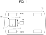
- FIG. 1 is a schematic view of the vehicle drive device 100 mounted on a vehicle VC, as viewed from above.
- FIG. 2 is a sectional view of a main part of the vehicle drive device 100.
- FIG. 2A is a skeleton diagram showing the vehicle drive device 100.
- the vehicle drive device 100 includes a rotating electrical machine 1, a pair of output members 6 each drivingly connected to a corresponding one of a pair of wheels W (see FIG. 1 ), and a transmission mechanism 3 that transmits a driving force between the rotating electrical machine 1 and the pair of output members 6.
- the vehicle drive device 100 further includes a case 2 that houses the rotating electrical machine 1.
- the case 2 also houses the pair of output members 6 and the transmission mechanism 3.
- the case 2 may house only one of the pair of output members 6.
- the vehicle drive device 100 is applicable to any vehicle including the rotating electrical machine 1 such as a battery electric vehicle or a hybrid electric vehicle, and is also applicable to any vehicle with any drive system such as front-wheel drive or rear-wheel drive.
- a first output member 61 that is one of the pair of output members 6 is drivingly connected to a first wheel W1 that is one of the pair of wheels W
- a second output member 62 that is the other of the pair of output members 6 is drivingly connected to a second wheel W2 that is the other of the pair of wheels W.
- the vehicle VC on which the vehicle drive device 100 is mounted includes a first drive shaft 63 that rotates with the first wheel W1, and a second drive shaft 64 that rotates with the second wheel W2.
- the first drive shaft 63 is connected to the first wheel W1 via, for example, a constant velocity joint
- the second drive shaft 64 is connected to the second wheel W2 via, for example, a constant velocity joint.
- the first output member 61 is connected to the first drive shaft 63 so as to rotate with the first drive shaft 63
- the second output member 62 is connected to the second drive shaft 64 so as to rotate with the second drive shaft 64.
- the vehicle drive device 100 transmits output torque of the rotating electrical machine 1 to the pair of wheels W via the pair of output members 6 to cause the vehicle VC on which the vehicle drive device 100 is mounted to travel. That is, the rotating electrical machine 1 is a driving force source for the pair of wheels W.
- the pair of wheels W is a pair of right and left wheels (e.g., a pair of right and left front wheels or a pair of right and left rear wheels) of the vehicle VC.
- the rotating electrical machine 1 may be, for example, an alternating current rotating electrical machine driven by three-phase alternating currents.
- the rotating electrical machine 1 and the pair of output members 6 are disposed on two separate axes that are parallel to each other (specifically, a first axis C1 and a second axis C2). Specifically, the rotating electrical machine 1 is disposed on the first axis C1, and the pair of output members 6 is disposed on the second axis C2 different from the first axis C1.
- the first axis C1 and the second axis C2 are axes (imaginary axes) arranged parallel to each other.
- the transmission mechanism 3 includes, coaxially with the pair of output members 6 (i.e., on the second axis C2), an output gear (ring gear) 30 drivingly connected to at least one of the pair of output members 6.
- the rotating electrical machine 1 is of, for example, an inner rotor type.
- a rotor (not shown) that is rotatable about the first axis C1 is disposed radially inward of a stator core 11 (see FIG. 4 ).
- the transmission mechanism 3 includes a speed reduction mechanism 34 in a power transmission path between the rotating electrical machine 1 and the output gear 30.
- the speed reduction mechanism 34 may be any speed reduction mechanism, and may include a speed reduction mechanism using a counter gear, a speed reduction mechanism using a planetary gear, etc.
- the speed reduction mechanism 34 includes a planetary gear mechanism, and the speed reduction mechanism 34 is disposed coaxially with the rotating electrical machine 1.
- An output gear (carrier) 342 of the speed reduction mechanism 34 meshes with the output gear 30 of the differential gear mechanism 5 in the radial direction.
- Such a vehicle drive device 100 can have a compact configuration with two axes (first axis C1 and second axis C2). In a modification, the vehicle drive device 100 may have three or more axes.
- the speed reduction mechanism 34 is disposed coaxially with the rotating electrical machine 1 (that is, on the first axis C1) so as to be drivingly connected to the rotating electrical machine 1.
- the rotor of the rotating electrical machine 1 together with a sun gear 341 of the speed reduction mechanism 34 rotates with the input member 16.
- the transmission mechanism 3 further includes a differential gear mechanism 5.
- the differential gear mechanism 5 distributes, to the pair of output members 6, the driving force transmitted from the rotating electrical machine 1 side.
- the differential gear mechanism 5 may be disposed coaxially with the pair of output members 6 (that is, on the second axis C2).
- the differential gear mechanism 5 distributes the driving force transmitted from the rotating electrical machine 1 side to the output gear 30 to the pair of output members 6. That is, the output gear 30 is drivingly connected to both of the pair of output members 6 via the differential gear mechanism 5.
- FIG. 3 is a top view schematically showing the vehicle drive device 100 according to the present embodiment
- FIG. 4 is a side view schematically showing the vehicle drive device 100 according to the present embodiment.
- an inverter cover member 203 (see FIGS. 2 and 4 ) that covers the top of an inverter case portion 24 is not shown in order to show elements disposed inside the inverter case portion 24.
- a motor cover member 201 is not shown and the rotor of the rotating electrical machine 1 is also not shown for better understanding of the state in a motor housing chamber S1.
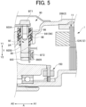
- FIG. 5 is a partial sectional view taken along line A-A in FIG. 3 , and corresponds to a portion Q5 in FIG. 2 .
- FIG. 6 is a four-view diagram of a terminal device 90.
- FIG. 7 is an illustration of a manner in which the terminal device 90 and a power line busbar 89 are coupled.
- the case 2 is formed by joining a case member 200, the motor cover member 201, a differential cover member 202, and the inverter cover member 203 (see FIGS. 2 and 4 ).
- the case member 200 forms the motor housing chamber S1, an inverter housing chamber S4, a transmission mechanism housing chamber, an output shaft housing chamber, etc.
- the joining method may be fastening with bolts etc.
- the vehicle drive device 100 further includes an inverter device 70, a high-voltage wiring portion 80, and a low-voltage wiring portion 140.
- the inverter device 70 may be housed in the case 2, or may be disposed at a position separate from the case 2.
- the inverter device 70 is disposed in the inverter case portion 24 in an upper part of the case 2.
- the inverter case portion 24 may be provided above a transmission mechanism case portion 22 and an output shaft case portion 23.
- the inverter device 70 is electrically connected between a battery BA (including an energy storage device such as a capacitor) and the rotating electrical machine 1, and performs power conversion between direct current power and alternating current power.
- the rotating electrical machine 1 is electrically connected to the battery BA via the inverter device 70.
- the rotating electrical machine 1 is supplied with electric power from the battery BA to perform power running, or supplies electric power generated by the inertial force of the vehicle VC etc. to the energy storage device to store the electric power in the energy storage device.
- the high-voltage wiring portion 80 electrically connects the rotating electrical machine 1 to the battery BA.
- the high-voltage wiring portion 80 includes a busbar member 88 from the inverter device 70, the power line busbar 89, and the terminal device 90.
- the busbar member 88 is in the form of three plates corresponding to the three phases, and may include a portion extending linearly in the axial direction.
- the busbar member 88 may be disposed inside the inverter case portion 24.
- An end of the busbar member 88 on the A1 side in the A-direction is fastened to the terminal device 90 with bolts BT1.
- a current sensor 889 is provided on the busbar member 88.
- the current sensor 889 is provided for each phase, and generates an electrical signal according to the magnitude of the current flowing through the busbar member 88.
- the current sensor 889 may be in an integrated form with the busbar member 88 that is obtained by resin molding etc. In the example shown in FIG. 3 , a terminal of the current sensor 889 is joined on the X2 side to a control board 72 (described later).
- the power line busbar 89 may be in the form of three busbars corresponding to the three phases.
- the power line busbar 89 is extended from a coil end 12A (see FIG. 5 ) of the rotating electrical machine 1 on the A2 side in the A-direction.
- the power line busbars 89 may extend further toward the A2 side in the A-direction with respect to an end face of the stator core 11 of the rotating electrical machine 1 on the A2 side in the A-direction.
- One end of the power line busbar 89 is joined to a stator coil 12 (see FIG. 5 ) of the rotating electrical machine 1, and the other end thereof is fastened to the terminal device 90 with a bolt BT2.
- the power line busbar 89 may be implemented as a component of the rotating electrical machine 1.
- the terminal device 90 is attached to the case on the A2 side of the rotating electrical machine 1 in the A-direction.
- the terminal device 90 electrically connects the busbar member 88 and the power line busbar 89 from the rotating electrical machine 1.
- the terminal device 90 includes a conductor portion 92, a fixing portion 94, a first seal portion 96, and a second seal portion 98.
- the conductor portion 92 electrically connects the busbar member 88 and the power line busbar 89.
- Three conductor portions 92 are provided corresponding to the three phases.
- the conductor portions 92 may be arranged next to each other in the X-direction. In the present embodiment, as shown in FIG. 7 , the conductor portions 92 are arranged in such a manner that the center of each conductor portion 92 is offset toward the X1 side with respect to the first axis C1. However, the conductor portions 92 may be arranged in such a manner that the center of each conductor portion 92 is located on the first axis C1 or that the center of each conductor portion 92 is offset toward the X2 side with respect to the first axis C1.
- Each conductor portion 92 may extend in the up-down direction with, for example, an equal cross section (i.e., a cross section taken along a plane perpendicular to the up-down direction is constant).
- the cross-sectional shape of each conductor portion 92 may be a rectangle or may be other shape.
- the size and shape of the cross section (cross section taken along a plane perpendicular to the up-down direction) of each conductor portion 92 may be designed so that a screw hole 921 for a bolt BT1 described later can be formed therein.
- Each conductor portion 92 is integrated with the fixing portion 94.
- Each conductor portion 92 extends in the up-down direction with its upper part exposed inside the inverter housing chamber S4 of the inverter case portion 24 and its lower part exposed inside the motor housing chamber S1.
- the entire conductor portion 92 preferably extends linearly in the up-down direction, or a part of the conductor portion 92 that is located in the motor housing chamber S1 extends linearly in the up-down direction.
- the hole shape of a mounting hole 2A see FIG.
- the mounting hole 2A is a hole that connects the motor housing chamber S1 and the inverter housing chamber S4, and is closed by mounting the terminal device 90.
- each conductor portion 92 preferably has, in the upper surface of the upper end 920A, a screw hole 921 for fastening the busbar member 88.
- a bolt BT1 is tightened into the fastening screw hole 921 through a bolt insertion hole in an end of the busbar member 88.
- the busbar member 88 is thus fastened in the up-down direction to the upper part of the conductor portion 92 with the bolt BT1.
- each conductor portion 92 itself serves as a bolt seat, which can save space.
- no separate structure such as a nut is needed, so that the size of the terminal device 90 can be reduced.
- each conductor portion 92 The power line busbar 89 from the rotating electrical machine 1 is fastened to a lower end 920B of each conductor portion 92 with a bolt BT2.
- the lower end 920B of each conductor portion 92 has, in its side surface facing the A1 side in the A-direction, a screw hole 922 for fastening a bolt BT2.
- each conductor portion 92 itself serves as a bolt seat, which can save space.
- no separate structure such as a nut is needed, so that the size of the terminal device 90 can be reduced.
- the lower ends 920B of the conductor portions 92 may be disposed at the same axial position, or may be offset from each other in the axial direction. When the lower ends 920B of the conductor portions 92 are disposed at the same axial position, the sizes of a body portion 941 and the mounting hole 2A can be reduced.
- the fastening positions for the bolts BT1, BT2 are respectively set on the upper surface of each linear conductor portion 92 and the side surface of the lower end 920B of each linear conductor portion 92.
- the size of the vehicle drive device 100 in a direction crossing the up-down direction can be reduced compared to a comparative configuration (not shown) in which the fastening positions for the bolts BT1, BT2 are offset from each other in this direction.
- each power line busbar 89 and the lower end 920B of a corresponding one of the conductor portions 92 is increased. Therefore, even when an allowable tolerance such as an allowable dimensional tolerance is relatively loosened for the power line busbar 89, significant stress due to tightening of the bolt BT2 is less likely to occur.
- each conductor portion 92 is disposed radially inward of the stator core 11 of the rotating electrical machine 1 as viewed in the axial direction. That is, the connection portion (fastening portion) between each conductor portion 92 and a corresponding one of the power line busbars 89 from the rotating electrical machine 1 is disposed radially inward of the stator core 11 of the rotating electrical machine 1.
- the work of fastening the conductor portions 92 and the power line busbars 89 from the rotating electrical machine 1 can thus be implemented with ease by using the space radially inward of the stator core 11.
- the terminal device 90 is disposed on the A2 side of the rotating electrical machine 1 in the A-direction, that is, on the opposite side from the motor cover member 201 located on the A1 side in the A-direction, as described above.
- Such an arrangement is advantageous in that the distance to the busbar member 88 disposed above the transmission mechanism case portion 22 can be reduced (and therefore, the wiring length can be reduced).
- the work of tightening the bolts BT2 tends to become less easy.
- each conductor portion 92 i.e., the coupling portion between each conductor portion 92 and a corresponding one of the power line busbars 89
- the lower ends 920B of the conductor portions 92 and the bolt insertion holes 8920 of the power line busbars 89 are visible (i.e., the fastening portions for the bolts BT2 are visible) as viewed in the axial direction. Accordingly, a fastening tool can be easily inserted in the axial direction toward the fastening portions, and the work of fastening each conductor portion 92 and a corresponding one of the power line busbars 89 can be implemented with ease.
- the fixing portion 94 may be made of, for example, a resin material.
- the fixing portion 94 holds each conductor portion 92.
- the fixing portion 94 is fastened to the case 2 with bolts BT3.
- the fixing portion 94 includes the body portion 941 and legs 942.
- the body portion 941 is inserted into and fitted into the mounting hole 2A of the case 2.
- the body portion 941 has substantially the same outer shape as the mounting hole 2A of the case 2 as viewed in the axial direction, and is disposed so as to close the mounting hole 2A.
- the legs 942 extend in the X-direction continuously from both sides of the body portion 941 in the X-direction.
- Each leg 942 has a bolt insertion hole through which the bolt BT3 passes.
- the bolts BT3 may be tightened into screw holes (not shown) provided in a bottom wall 29 (wall in which the above mounting hole 2A is formed) that forms the inverter housing chamber S4 in the case 2.
- the first seal portion 96 seals between the conductor portion 92 and the fixing portion 94.
- the first seal portion 96 implements a sealing structure against oil inside the terminal device 90. Specifically, the first seal portion 96 prevents oil from entering from the motor housing chamber S1 into the inverter housing chamber S4 through between the conductor portion 92 and the fixing portion 94 of the terminal device 90. This reduces the possibility that oil in the motor housing chamber S1 may leak into the inverter housing chamber S4.
- the first seal portion 96 is provided for each conductor portion 92, and is formed around the conductor portion 92 so as to closely contact the conductor portion 92 and the fixing portion 94.
- the first seal portion 96 may be molded integrally with the fixing portion 94. In the example shown in FIG.
- the first seal portion 96 is provided only in an upper part of the range in the up-down direction in which the conductor portion 92 is surrounded by the fixing portion 94.
- the first seal portion 96 may be provided in the entire range in the up-down direction in which the conductor portion 92 is surrounded by the fixing portion 94, or may be provided in a lower part of the range in the up-down direction in which the conductor portion 92 is surrounded by the fixing portion 94.
- the second seal portion 98 seals between the outer periphery of the fixing portion 94 of the terminal device 90 and the case 2.
- the second seal portion 98 may be provided around the entire outer periphery of the fixing portion 94.
- the second seal portion 98 is disposed around the body portion 941 of the fixing portion 94 and closely contacts the body portion 941 and the wall surface of the mounting hole 2A.
- the second seal portion 98 may be made of, for example, a rubber material, and may be in the form of an O-ring.
- the second seal portion 98 prevents oil from entering from the motor housing chamber S1 into the inverter housing chamber S4 through the mounting hole 2A (particularly between the outer periphery of the fixing portion 94 and the case 2). This reduces the possibility that oil in the motor housing chamber S1 may leak into the inverter housing chamber S4.
- the screw hole 921 for the bolt BT1 does not extend through the conductor portion 92 in the up-down direction, and is open only on its upper side.
- the entire bolt BT2 extends into the motor housing chamber S1. Therefore, in the present embodiment, there is no possibility that oil may enter from around the bolt BT1 and around the bolt BT2 (that oil may enter the inverter housing chamber S4). Accordingly, there is no need to provide a separate seal structure above the bolt BT1 etc. This reduces an increase in size due to the seal structure compared to the case where a cap etc. is provided above the bolt BT1 etc.
- the screw hole 922 is provided in the lower end 920B of each conductor portion 92, as described above. This allows the entire bolt BT2 to be located in the motor housing chamber S1. Since each conductor portion 92 extends in the up-down direction, the screw hole 921 for the bolt BT1 can be provided as a non-through hole. This eliminates the need for measures against oil leakage through the bolt BT1 and the bolt BT2, and therefore, can simplify the seal structure.
- the low-voltage wiring portion 140 electrically connects a plurality of low-voltage components 144 (see FIG. 8 ) disposed in the motor housing chamber S1 to the control board 72.
- the low-voltage wiring portion 140 may be in the form of a bundle of harnesses each connected to a corresponding one of the plurality of low-voltage components 144.
- the control board 72 extends between the inverter device 70 and the inverter cover member 203 so as to cover the upper side of the inverter device 70.
- the plurality of low-voltage components 144 includes a rotation angle detection device 150 (rotation angle sensor) described later. Some examples of the low-voltage components 144 will be described later.
- the low-voltage wiring portion 140 includes a wiring portion routed inside the inverter housing chamber S4 (hereinafter also referred to as “inverter-side low-voltage wiring portion 141") and a wiring portion routed inside the motor housing chamber S1 (hereinafter also referred to as the "motor chamber-side low-voltage wiring portion 142").
- the inverter-side low-voltage wiring portion 141 and the motor chamber-side low-voltage wiring portion 142 are connected via a connector CN4.
- the connector CN4 is fitted into a through hole (hole in the up-down direction) in the bottom wall 29 of the inverter housing chamber S4 (see FIG. 3 ).
- the inverter-side low-voltage wiring portion 141 may be disposed using the space between the terminal device 90 of the high-voltage wiring portion 80 and the sidewall 240 in the axial direction A in the inverter housing chamber S4.
- one end of the inverter-side low-voltage wiring portion 141 may be connected to the connector CN4, and the other end thereof may be fixed to the control board 72 via a connector CN2.
- the motor chamber-side low-voltage wiring portion 142 will be described in detail later with reference to FIG. 8 .
- each conductor portion 92 is preferably provided above the central axis (first axis C1) of the rotating electrical machine 1. This reduces the possibility or frequency of oil in the motor housing chamber S1 getting on each conductor portion 92.
- the rotation angle detection device 150 may be in the form of, for example, a resolver provided around a rotation shaft of the rotating electrical machine 1.
- a fixed element of the rotation angle detection device 150 has an annular portion 152 and a fastening portion 154.
- the annular portion 152 is located radially inward of the conductor portions 92 and extends around the central axis (first axis C1) of the rotating electrical machine 1.
- the fastening portion 154 is fastened to a wall of the case 2 (e.g., a wall extending in a plane crossing the axial direction in such a manner that the wall separates the motor housing chamber S1 and the transmission mechanism housing chamber) with a bolt BT4.
- a wall of the case 2 e.g., a wall extending in a plane crossing the axial direction in such a manner that the wall separates the motor housing chamber S1 and the transmission mechanism housing chamber
- a plurality of fastening portions 154 may be provided at equal intervals in a circumferential direction.
- the fastening portions 154 are provided at intervals of 120 degrees.
- the fastening portions 154 extend radially outward beyond the conductor portions 92. Therefore, the fastening portions 154 are disposed so as to be offset in the circumferential direction with respect to the conductor portion 92. This allows the lower end 920B of each conductor portion 92 and the rotation angle detection device 150 to be located radially inward of the stator core 11 as viewed in the axial direction and on the A2 side of the rotating electrical machine 1 in the A direction.
- each conductor portion 92 be located as far away from the central axis (first axis C1) of the rotating electrical machine 1 as possible in the region radially inward of the stator core 11 as viewed in the axial direction.
- each conductor portion 92 may be disposed at the farthest position or the uppermost position from the central axis (first axis C1) of the rotating electrical machine 1 in the region radially inward of the stator core 11 as viewed in the axial direction within a range in which necessary clearance is provided between a tool for tightening the bolt BT2 and the inner peripheral surface of the stator core 11.
- Such a configuration can be implemented by making the lengths of the conductor portions 92 different from each other. In other words, by making the lengths of the conductor portions 92 different from each other, the space for disposing other components such as the rotation angle detection device 150 can be efficiently secured in the region radially inward of the stator core 11 as viewed in the axial direction.
- FIG. 8 is a side view schematically showing the vehicle drive device 100 according to the present embodiment.
- the motor cover member 201 is not shown and the rotor of the rotating electrical machine 1 is also not shown for better understanding of the state in the motor housing chamber S1.
- FIG. 8 shows the motor chamber-side low-voltage wiring portion 142, part of which is not shown in FIG. 4 .
- the shapes and positions of the same components are shown slightly different between FIGS. 8 and 4 , such differences are not relevant to the description given below with reference to FIG. 8 .
- FIG. 8 mainly shows components disposed between the rotating electrical machine 1 and a partition wall 26 of the case 2 in the axial direction A out of various components housed in the motor housing chamber S1. That is, FIG. 8 shows the partition wall 26 and the components disposed between the rotating electrical machine 1 and the transmission mechanism 3 (particularly the speed reduction mechanism 34) in the axial direction A out of the various components housed in the motor housing chamber S1.
- FIG. 8 also shows, as a part of the components of the rotating electrical machine 1, the power line busbar 89 joined to the conductor portion 92 of the terminal device 90.
- the power line busbar 89 may be in the form of an integrated module obtained by, for example, by resin molding.
- the conductor portion 92 (and the power line busbar 89) of the terminal device 90 of the high-voltage wiring portion 80 and the motor chamber-side low-voltage wiring portion 142 are disposed in a space S11 (see FIG. 2 ) between the rotating electrical machine 1 and the partition wall 26 in the axial direction A in the motor housing chamber S1 of the case 2.
- the motor housing chamber S1 includes spaces S11, S12 on both sides of the rotating electrical machine 1 in the axial direction A, one space on each side.
- the space S11 is located between the rotating electrical machine 1 and the partition wall 26 in the axial direction A
- the space S12 is located between the rotating electrical machine 1 and the motor cover member 201 in the axial direction A.
- the conductor portion 92 of the terminal device 90 of the high-voltage wiring portion 80 and the motor chamber-side low-voltage wiring portion 142 are both disposed in the space S11.
- This arrangement can reduce the wiring length compared to the case where the conductor portion 92 of the terminal device 90 of the high-voltage wiring portion 80 and the motor chamber-side low-voltage wiring portion 142 are disposed in the separate spaces S11, S12. That is, as described above with reference to FIG. 3 , this arrangement allows wires to be extended from the upper part of the space S11 into the inverter housing chamber S4, and can thus reduce the wiring length to the inverter housing chamber S4.
- the motor chamber-side low-voltage wiring portion 142 is provided in a circumferential range different from that of the conductor portion 92 of the terminal device 90 (and the power line busbar 89) out of the circumferential range around the rotating electrical machine 1, as viewed in the axial direction. This allows the motor chamber-side low-voltage wiring portion 142 and the conductor portion 92 of the terminal device 90 (and the power line busbar 89) to be distributed and arranged so as not to overlap each other along the entire circumference of the rotating electrical machine 1 in the space S11.
- a line Lh is a horizontal straight line passing through the axis of the rotating electrical machine 1
- the entire conductor portion 92 of the terminal device 90 (and the power line busbar 89) is preferably located above the line Lh. This can minimize the wiring length between the terminal device 90 and the rotating electrical machine 1 described above.
- only part of the power line busbar 89 may be located below the line Lh.
- the motor chamber-side low-voltage wiring portion 142 is disposed in an angular range of 180 degrees below the axis of the rotating electrical machine 1 out of the range around the axis of the rotating electrical machine 1 (on the first axis C1).
- the motor chamber-side low-voltage wiring portion 142 is in the form of a harness including the connector CN4 described above at its one end and three connectors CN11, CN12, and CN13 at the other end.
- the connector CN4 is disposed at the end of the inverter housing chamber S4 on the X1 side.
- the end of the motor chamber-side low-voltage wiring portion 142 on the connector CN4 side is located on the X1 side of the conductor portion 92 in the X-direction as shown in FIG. 8 , as viewed in the axial direction.
- the motor chamber-side low-voltage wiring portion 142 extends from its end on the connector CN4 side, passes below the axis of the rotating electrical machine 1 in a clockwise direction as viewed in FIG. 8 , and branches into wiring portions 1421, 1422 to the connectors CN11, CN12 near the lowermost part of the motor housing chamber S1.
- the connector CN11 is connected to the rotation angle detection device 150 described above (example of the low-voltage components 144).
- the connector CN12 is connected to an oil temperature sensor 160.
- the oil temperature sensor 160 is an example of the low-voltage components 144, and generates an electrical signal according to the temperature of oil flowing in the lower part of the motor housing chamber S1.
- the remaining wiring portion 1423 of the motor chamber-side low-voltage wiring portion 142 is routed further in a clockwise direction as viewed in FIG. 8 from the branching position for the connectors CN11, CN12.
- the wiring portion 1423 ends such that the connector CN13 is located at approximately the same height (position in the Y-direction) as the axis of the rotating electrical machine 1.
- the connector CN13 is located on the X2 side with respect to the axis of the rotating electrical machine 1.
- the connector CN13 is connected to a temperature sensor 162 (example of the low-voltage components 144).
- the temperature sensor 162 is in the form of, for example, a thermistor, and generates an electrical signal according to the temperature of the rotating electrical machine 1.
- the temperature sensor 162 may be disposed near a portion of the rotating electrical machine 1 that tends to become relatively hot (e.g., the power line busbar 89).
- the motor chamber-side low-voltage wiring portion 142 can be routed by effectively using the space portion located below the axis of the rotating electrical machine 1 (angular range of 180 degrees around the axis) out of the space S11.
- the motor chamber-side low-voltage wiring portion 142 can be efficiently disposed in the same space S11 as the conductor portion 92 of the terminal device 90 (and the power line busbar 89).
- the motor chamber-side low-voltage wiring portion 142 is clamped to the partition wall 26 by clamps 143 at two positions across the branch position for CN11, CN12. This appropriately prevents vibration etc. of the motor chamber-side low-voltage wiring portion 142.
- the number and positions of the clamps 143 are not limited to this, and the clamps 143 may be in other forms.
- the vehicle drive device 100 includes the differential gear mechanism 5 in the case 2.
- the differential gear mechanism 5 may be configured to be disposed separately from the case including the rotating electrical machine 1 etc.
Landscapes
- Engineering & Computer Science (AREA)
- Mechanical Engineering (AREA)
- Power Engineering (AREA)
- Chemical & Material Sciences (AREA)
- Combustion & Propulsion (AREA)
- Transportation (AREA)
- Microelectronics & Electronic Packaging (AREA)
- Motor Or Generator Frames (AREA)
Abstract
Description
- The present disclosure relates to vehicle drive devices.
- There is known a technique of electrically connecting a power supply and a rotating electrical machine by attaching a terminal device in the form of a terminal block from outside a case that houses the rotating electrical machine and a power transmission device.
- Patent Document 1:
WO2016/035476 - In the above related art, however, a fastening portion between a conductor portion of the terminal device and a connection conductor from the rotating electrical machine is located radially outward of a stator core of the rotating electrical machine as viewed in an axial direction. It is therefore difficult to reduce the size of a vehicle drive device in a direction crossing the axial direction.
- In one aspect, an object of the present disclosure is to reduce the size of a vehicle drive device in a direction crossing an axial direction.
- One aspect provides a rotating electrical machine including: a rotating electrical machine;
- a power transmission device disposed on one side of the rotating electrical machine in an axial direction and configured to transmit power from the rotating electrical machine to a wheel;
- a wiring portion that electrically connects the rotating electrical machine to a power supply; and
- a case that houses the rotating electrical machine and the power transmission device.
- In one aspect, the present disclosure can reduce the size of a vehicle drive device in a direction crossing an axial direction.
-
- [
FIG. 1] FIG. 1 is a schematic view of a vehicle drive device mounted on a vehicle, as viewed from above. - [
FIG. 2] FIG. 2 is a sectional view of a main part of the vehicle drive device. - [
FIG. 2A] FIG. 2A is a skeleton diagram showing the vehicle drive device. - [
FIG. 3] FIG. 3 is a top view schematically showing a vehicle drive device according to an embodiment. - [
FIG. 4] FIG. 4 is a side view schematically showing the vehicle drive device according to the embodiment. - [
FIG. 5] FIG. 5 is a partial sectional view taken along line A-A inFIG. 3 . - [
FIG. 6] FIG. 6 is a four-view diagram of a terminal device. - [
FIG. 7] FIG. 7 is an illustration of a manner in which the terminal device and a power line busbar from a rotatingelectrical machine 1 are coupled. - [
FIG. 8] FIG. 8 is a side view schematically showing the vehicle drive device according to the embodiment. - Embodiments will be described in detail below with reference to the accompanying drawings. The dimensional ratios in the drawings are merely illustrative, and are not limited to these. The shapes etc. in the drawings may be partially exaggerated for convenience of description.
- In the following description, the Y-direction (see
FIG. 4 etc.) means an up-down direction when avehicle drive device 100 is in use, that is, an up-down direction when thevehicle drive device 100 is disposed in an orientation in which it is supposed to be used. The Y1 side and the Y2 side correspond to the upper side and the lower side along the Y direction. The up-down direction need not necessarily be parallel to a vertical direction, and need only predominantly include a vertical direction component. The direction of each member in the following description represents the direction of the member mounted on thevehicle drive device 100. Terms related to the dimension of each member, the direction in which each member is disposed, and the position where each member is disposed, etc. represent concepts including a state in which there is a deviation due to a variation (variation to an extent that is allowable in manufacturing). The A-direction (seeFIG. 2 etc.) corresponds to an axial direction, and the A1 side and the A2 side in the A direction are defined inFIG. 2 etc. The X-direction (seeFIG. 3 etc.) is a direction perpendicular to both the A-direction and the Y-direction, the X1 side and the X2 side in the X direction are defined inFIG. 3 etc. - In the present application, "drivingly connected" refers to a state in which two rotating elements are connected such that a driving force (synonymous with torque) can be transmitted therebetween, and includes a state in which the two rotating elements are connected so as to rotate together or a state in which the two rotating elements are connected such that a driving force can be transmitted therebetween via one or more transmission members. Such transmission members include various members that transmit rotation at the same speed or at a shifted speed (e.g., a shaft, a gear mechanism, a belt, and a chain). The transmission members may include engagement devices that selectively transmit rotation and a driving force (e.g., a friction engagement device and an intermesh engagement device).
- In the present specification, the "rotating electrical machine" is used as a concept including a motor (electric motor), a generator (power generator), and a motor generator that functions as both a motor and a generator as necessary. In the present specification, regarding arrangement of two members, the "two members overlap each other as viewed in a specific direction" means that, when an imaginary straight line parallel to the direction of the line of sight is moved in all directions perpendicular to the imaginary straight line, an area where the imaginary straight line intersects both of the two members is preset at least in part. In the present specification, regarding arrangement of two members, the "regions in a specific direction where the two members are disposed overlap each other" means that the region in the specific direction where one member is disposed includes at least part of the region in the specific direction where the other member is disposed.
-
FIG. 1 is a schematic view of thevehicle drive device 100 mounted on a vehicle VC, as viewed from above.FIG. 2 is a sectional view of a main part of thevehicle drive device 100.FIG. 2A is a skeleton diagram showing thevehicle drive device 100. - As schematically shown in
FIGS. 1 and2A , thevehicle drive device 100 includes a rotatingelectrical machine 1, a pair ofoutput members 6 each drivingly connected to a corresponding one of a pair of wheels W (seeFIG. 1 ), and atransmission mechanism 3 that transmits a driving force between the rotatingelectrical machine 1 and the pair ofoutput members 6. Thevehicle drive device 100 further includes acase 2 that houses the rotatingelectrical machine 1. Thecase 2 also houses the pair ofoutput members 6 and thetransmission mechanism 3. In a modification, thecase 2 may house only one of the pair ofoutput members 6. Thevehicle drive device 100 is applicable to any vehicle including the rotatingelectrical machine 1 such as a battery electric vehicle or a hybrid electric vehicle, and is also applicable to any vehicle with any drive system such as front-wheel drive or rear-wheel drive. - A
first output member 61 that is one of the pair ofoutput members 6 is drivingly connected to a first wheel W1 that is one of the pair of wheels W, and asecond output member 62 that is the other of the pair ofoutput members 6 is drivingly connected to a second wheel W2 that is the other of the pair of wheels W. As shown inFIG. 1 , the vehicle VC on which thevehicle drive device 100 is mounted includes afirst drive shaft 63 that rotates with the first wheel W1, and asecond drive shaft 64 that rotates with the second wheel W2. Thefirst drive shaft 63 is connected to the first wheel W1 via, for example, a constant velocity joint, and thesecond drive shaft 64 is connected to the second wheel W2 via, for example, a constant velocity joint. Thefirst output member 61 is connected to thefirst drive shaft 63 so as to rotate with thefirst drive shaft 63, and thesecond output member 62 is connected to thesecond drive shaft 64 so as to rotate with thesecond drive shaft 64. - The
vehicle drive device 100 transmits output torque of the rotatingelectrical machine 1 to the pair of wheels W via the pair ofoutput members 6 to cause the vehicle VC on which thevehicle drive device 100 is mounted to travel. That is, the rotatingelectrical machine 1 is a driving force source for the pair of wheels W. The pair of wheels W is a pair of right and left wheels (e.g., a pair of right and left front wheels or a pair of right and left rear wheels) of the vehicle VC. The rotatingelectrical machine 1 may be, for example, an alternating current rotating electrical machine driven by three-phase alternating currents. - As shown in
FIG. 2A , the rotatingelectrical machine 1 and the pair ofoutput members 6 are disposed on two separate axes that are parallel to each other (specifically, a first axis C1 and a second axis C2). Specifically, the rotatingelectrical machine 1 is disposed on the first axis C1, and the pair ofoutput members 6 is disposed on the second axis C2 different from the first axis C1. The first axis C1 and the second axis C2 are axes (imaginary axes) arranged parallel to each other. Thetransmission mechanism 3 includes, coaxially with the pair of output members 6 (i.e., on the second axis C2), an output gear (ring gear) 30 drivingly connected to at least one of the pair ofoutput members 6. - The rotating
electrical machine 1 is of, for example, an inner rotor type. In the rotatingelectrical machine 1, a rotor (not shown) that is rotatable about the first axis C1 is disposed radially inward of a stator core 11 (seeFIG. 4 ). - The
transmission mechanism 3 includes aspeed reduction mechanism 34 in a power transmission path between the rotatingelectrical machine 1 and theoutput gear 30. Thespeed reduction mechanism 34 may be any speed reduction mechanism, and may include a speed reduction mechanism using a counter gear, a speed reduction mechanism using a planetary gear, etc. In the present embodiment, as an example, thespeed reduction mechanism 34 includes a planetary gear mechanism, and thespeed reduction mechanism 34 is disposed coaxially with the rotatingelectrical machine 1. An output gear (carrier) 342 of thespeed reduction mechanism 34 meshes with theoutput gear 30 of thedifferential gear mechanism 5 in the radial direction. Such avehicle drive device 100 can have a compact configuration with two axes (first axis C1 and second axis C2). In a modification, thevehicle drive device 100 may have three or more axes. - In the present embodiment, the
speed reduction mechanism 34 is disposed coaxially with the rotating electrical machine 1 (that is, on the first axis C1) so as to be drivingly connected to the rotatingelectrical machine 1. In the present embodiment, as an example, the rotor of the rotatingelectrical machine 1 together with asun gear 341 of thespeed reduction mechanism 34 rotates with theinput member 16. - The
transmission mechanism 3 further includes adifferential gear mechanism 5. Thedifferential gear mechanism 5 distributes, to the pair ofoutput members 6, the driving force transmitted from the rotatingelectrical machine 1 side. Thedifferential gear mechanism 5 may be disposed coaxially with the pair of output members 6 (that is, on the second axis C2). Thedifferential gear mechanism 5 distributes the driving force transmitted from the rotatingelectrical machine 1 side to theoutput gear 30 to the pair ofoutput members 6. That is, theoutput gear 30 is drivingly connected to both of the pair ofoutput members 6 via thedifferential gear mechanism 5. - Next, a wiring structure etc. according to the present embodiment will be described with reference to
FIG. 3 and the subsequent figures. -
FIG. 3 is a top view schematically showing thevehicle drive device 100 according to the present embodiment, andFIG. 4 is a side view schematically showing thevehicle drive device 100 according to the present embodiment. InFIG. 3 , an inverter cover member 203 (seeFIGS. 2 and4 ) that covers the top of aninverter case portion 24 is not shown in order to show elements disposed inside theinverter case portion 24. InFIG. 4 , amotor cover member 201 is not shown and the rotor of the rotatingelectrical machine 1 is also not shown for better understanding of the state in a motor housing chamber S1. -
FIG. 5 is a partial sectional view taken along line A-A inFIG. 3 , and corresponds to a portion Q5 inFIG. 2 .FIG. 6 is a four-view diagram of aterminal device 90.FIG. 7 is an illustration of a manner in which theterminal device 90 and apower line busbar 89 are coupled. - As shown in
FIG. 3 , it is assumed that thecase 2 is formed by joining acase member 200, themotor cover member 201, adifferential cover member 202, and the inverter cover member 203 (seeFIGS. 2 and4 ). Thecase member 200 forms the motor housing chamber S1, an inverter housing chamber S4, a transmission mechanism housing chamber, an output shaft housing chamber, etc. The joining method may be fastening with bolts etc. - In the present embodiment, the
vehicle drive device 100 further includes aninverter device 70, a high-voltage wiring portion 80, and a low-voltage wiring portion 140. Theinverter device 70 may be housed in thecase 2, or may be disposed at a position separate from thecase 2. In the present embodiment, as an example, theinverter device 70 is disposed in theinverter case portion 24 in an upper part of thecase 2. As shown inFIGS. 3 and4 , theinverter case portion 24 may be provided above a transmissionmechanism case portion 22 and an outputshaft case portion 23. - The
inverter device 70 is electrically connected between a battery BA (including an energy storage device such as a capacitor) and the rotatingelectrical machine 1, and performs power conversion between direct current power and alternating current power. The rotatingelectrical machine 1 is electrically connected to the battery BA via theinverter device 70. The rotatingelectrical machine 1 is supplied with electric power from the battery BA to perform power running, or supplies electric power generated by the inertial force of the vehicle VC etc. to the energy storage device to store the electric power in the energy storage device. - The high-
voltage wiring portion 80 electrically connects the rotatingelectrical machine 1 to the battery BA. The high-voltage wiring portion 80 includes abusbar member 88 from theinverter device 70, thepower line busbar 89, and theterminal device 90. - The
busbar member 88 is in the form of three plates corresponding to the three phases, and may include a portion extending linearly in the axial direction. Thebusbar member 88 may be disposed inside theinverter case portion 24. An end of thebusbar member 88 on the A1 side in the A-direction is fastened to theterminal device 90 with bolts BT1. Acurrent sensor 889 is provided on thebusbar member 88. Thecurrent sensor 889 is provided for each phase, and generates an electrical signal according to the magnitude of the current flowing through thebusbar member 88. Thecurrent sensor 889 may be in an integrated form with thebusbar member 88 that is obtained by resin molding etc. In the example shown inFIG. 3 , a terminal of thecurrent sensor 889 is joined on the X2 side to a control board 72 (described later). - The
power line busbar 89 may be in the form of three busbars corresponding to the three phases. Thepower line busbar 89 is extended from acoil end 12A (seeFIG. 5 ) of the rotatingelectrical machine 1 on the A2 side in the A-direction. The power line busbars 89 may extend further toward the A2 side in the A-direction with respect to an end face of thestator core 11 of the rotatingelectrical machine 1 on the A2 side in the A-direction. One end of thepower line busbar 89 is joined to a stator coil 12 (seeFIG. 5 ) of the rotatingelectrical machine 1, and the other end thereof is fastened to theterminal device 90 with a bolt BT2. Thepower line busbar 89 may be implemented as a component of the rotatingelectrical machine 1. - The
terminal device 90 is attached to the case on the A2 side of the rotatingelectrical machine 1 in the A-direction. Theterminal device 90 electrically connects thebusbar member 88 and thepower line busbar 89 from the rotatingelectrical machine 1. - As shown in
FIG. 6 , theterminal device 90 includes aconductor portion 92, a fixingportion 94, afirst seal portion 96, and asecond seal portion 98. - The
conductor portion 92 electrically connects thebusbar member 88 and thepower line busbar 89. Threeconductor portions 92 are provided corresponding to the three phases. Theconductor portions 92 may be arranged next to each other in the X-direction. In the present embodiment, as shown inFIG. 7 , theconductor portions 92 are arranged in such a manner that the center of eachconductor portion 92 is offset toward the X1 side with respect to the first axis C1. However, theconductor portions 92 may be arranged in such a manner that the center of eachconductor portion 92 is located on the first axis C1 or that the center of eachconductor portion 92 is offset toward the X2 side with respect to the first axis C1. - Each
conductor portion 92 may extend in the up-down direction with, for example, an equal cross section (i.e., a cross section taken along a plane perpendicular to the up-down direction is constant). In this case, the cross-sectional shape of eachconductor portion 92 may be a rectangle or may be other shape. In the present embodiment, the size and shape of the cross section (cross section taken along a plane perpendicular to the up-down direction) of eachconductor portion 92 may be designed so that ascrew hole 921 for a bolt BT1 described later can be formed therein. - Each
conductor portion 92 is integrated with the fixingportion 94. Eachconductor portion 92 extends in the up-down direction with its upper part exposed inside the inverter housing chamber S4 of theinverter case portion 24 and its lower part exposed inside the motor housing chamber S1. Theentire conductor portion 92 preferably extends linearly in the up-down direction, or a part of theconductor portion 92 that is located in the motor housing chamber S1 extends linearly in the up-down direction. In this case, the hole shape of a mountinghole 2A (seeFIG. 5 ) of thecase 2 for mounting the fixingportion 94 can be reduced in size compared to the case where the part of theconductor portion 92 that is located in the motor housing chamber S1 is bent in the X-direction or the A-direction. The mountinghole 2A is a hole that connects the motor housing chamber S1 and the inverter housing chamber S4, and is closed by mounting theterminal device 90. - The
busbar member 88 is fastened to anupper end 920A of eachconductor portion 92. As shown inFIG. 6 , eachconductor portion 92 preferably has, in the upper surface of theupper end 920A, ascrew hole 921 for fastening thebusbar member 88. A bolt BT1 is tightened into thefastening screw hole 921 through a bolt insertion hole in an end of thebusbar member 88. Thebusbar member 88 is thus fastened in the up-down direction to the upper part of theconductor portion 92 with the bolt BT1. In this case, eachconductor portion 92 itself serves as a bolt seat, which can save space. Moreover, no separate structure such as a nut is needed, so that the size of theterminal device 90 can be reduced. - The
power line busbar 89 from the rotatingelectrical machine 1 is fastened to alower end 920B of eachconductor portion 92 with a bolt BT2. Thelower end 920B of eachconductor portion 92 has, in its side surface facing the A1 side in the A-direction, ascrew hole 922 for fastening a bolt BT2. In this case, eachconductor portion 92 itself serves as a bolt seat, which can save space. Moreover, no separate structure such as a nut is needed, so that the size of theterminal device 90 can be reduced. - The lower ends 920B of the
conductor portions 92 may be disposed at the same axial position, or may be offset from each other in the axial direction. When the lower ends 920B of theconductor portions 92 are disposed at the same axial position, the sizes of abody portion 941 and the mountinghole 2A can be reduced. - As described above, according to the present embodiment, the fastening positions for the bolts BT1, BT2 are respectively set on the upper surface of each
linear conductor portion 92 and the side surface of thelower end 920B of eachlinear conductor portion 92. As a result, according to the present embodiment, the size of thevehicle drive device 100 in a direction crossing the up-down direction can be reduced compared to a comparative configuration (not shown) in which the fastening positions for the bolts BT1, BT2 are offset from each other in this direction. - As shown in
FIG. 4 , thepower line busbar 89 includes afastening portion 892 extending radially inward at thecoil end 12A of the rotatingelectrical machine 1 on the A2 side in the A-direction. Thefastening portion 892 is in the form of a plate, and has abolt insertion hole 8920. Thefastening portions 892 of the power line busbars 89 of the phases contact, in a one-to-one relationship, the side surfaces (side surfaces facing the A1 side in the A-direction) of the lower ends 920B of theconductor portions 92, and are fastened thereto in the axial direction with the bolts BT2. In this case, the bolt insertion hole 8920 (seeFIG. 5 ) may have an inner diameter that is relatively larger than the outer diameter of a shaft portion of the bolt BT2. In the case of such fastening, the level of tolerance for misalignment between eachpower line busbar 89 and thelower end 920B of a corresponding one of theconductor portions 92 is increased. Therefore, even when an allowable tolerance such as an allowable dimensional tolerance is relatively loosened for thepower line busbar 89, significant stress due to tightening of the bolt BT2 is less likely to occur. - In the present embodiment, the
lower end 920B of eachconductor portion 92 is disposed radially inward of thestator core 11 of the rotatingelectrical machine 1 as viewed in the axial direction. That is, the connection portion (fastening portion) between eachconductor portion 92 and a corresponding one of the power line busbars 89 from the rotatingelectrical machine 1 is disposed radially inward of thestator core 11 of the rotatingelectrical machine 1. The work of fastening theconductor portions 92 and the power line busbars 89 from the rotatingelectrical machine 1 can thus be implemented with ease by using the space radially inward of thestator core 11. - More specifically, in the present embodiment, the
terminal device 90 is disposed on the A2 side of the rotatingelectrical machine 1 in the A-direction, that is, on the opposite side from themotor cover member 201 located on the A1 side in the A-direction, as described above. Such an arrangement is advantageous in that the distance to thebusbar member 88 disposed above the transmissionmechanism case portion 22 can be reduced (and therefore, the wiring length can be reduced). However, on the other hand, since the axial distance from a case opening that is covered by themotor cover member 201 is increased, the work of tightening the bolts BT2 tends to become less easy. - In the present embodiment, however, the
lower end 920B of each conductor portion 92 (i.e., the coupling portion between eachconductor portion 92 and a corresponding one of the power line busbars 89) is disposed radially inward of thestator core 11 of the rotatingelectrical machine 1 as viewed in the axial direction. Therefore, as shown inFIG. 4 , in a state before the rotor (not shown) is attached, the lower ends 920B of theconductor portions 92 and thebolt insertion holes 8920 of the power line busbars 89 are visible (i.e., the fastening portions for the bolts BT2 are visible) as viewed in the axial direction. Accordingly, a fastening tool can be easily inserted in the axial direction toward the fastening portions, and the work of fastening eachconductor portion 92 and a corresponding one of the power line busbars 89 can be implemented with ease. - The fixing
portion 94 may be made of, for example, a resin material. The fixingportion 94 holds eachconductor portion 92. The fixingportion 94 is fastened to thecase 2 with bolts BT3. The fixingportion 94 includes thebody portion 941 andlegs 942. Thebody portion 941 is inserted into and fitted into the mountinghole 2A of thecase 2. Thebody portion 941 has substantially the same outer shape as the mountinghole 2A of thecase 2 as viewed in the axial direction, and is disposed so as to close the mountinghole 2A. Thelegs 942 extend in the X-direction continuously from both sides of thebody portion 941 in the X-direction. Eachleg 942 has a bolt insertion hole through which the bolt BT3 passes. The bolts BT3 may be tightened into screw holes (not shown) provided in a bottom wall 29 (wall in which the above mountinghole 2A is formed) that forms the inverter housing chamber S4 in thecase 2. - The
first seal portion 96 seals between theconductor portion 92 and the fixingportion 94. Thefirst seal portion 96 implements a sealing structure against oil inside theterminal device 90. Specifically, thefirst seal portion 96 prevents oil from entering from the motor housing chamber S1 into the inverter housing chamber S4 through between theconductor portion 92 and the fixingportion 94 of theterminal device 90. This reduces the possibility that oil in the motor housing chamber S1 may leak into the inverter housing chamber S4. Thefirst seal portion 96 is provided for eachconductor portion 92, and is formed around theconductor portion 92 so as to closely contact theconductor portion 92 and the fixingportion 94. Thefirst seal portion 96 may be molded integrally with the fixingportion 94. In the example shown inFIG. 5 , thefirst seal portion 96 is provided only in an upper part of the range in the up-down direction in which theconductor portion 92 is surrounded by the fixingportion 94. However, thefirst seal portion 96 may be provided in the entire range in the up-down direction in which theconductor portion 92 is surrounded by the fixingportion 94, or may be provided in a lower part of the range in the up-down direction in which theconductor portion 92 is surrounded by the fixingportion 94. - The
second seal portion 98 seals between the outer periphery of the fixingportion 94 of theterminal device 90 and thecase 2. Thesecond seal portion 98 may be provided around the entire outer periphery of the fixingportion 94. Thesecond seal portion 98 is disposed around thebody portion 941 of the fixingportion 94 and closely contacts thebody portion 941 and the wall surface of the mountinghole 2A. Thesecond seal portion 98 may be made of, for example, a rubber material, and may be in the form of an O-ring. Thesecond seal portion 98 prevents oil from entering from the motor housing chamber S1 into the inverter housing chamber S4 through the mountinghole 2A (particularly between the outer periphery of the fixingportion 94 and the case 2). This reduces the possibility that oil in the motor housing chamber S1 may leak into the inverter housing chamber S4. - In the present embodiment, the
screw hole 921 for the bolt BT1 does not extend through theconductor portion 92 in the up-down direction, and is open only on its upper side. The entire bolt BT2 extends into the motor housing chamber S1. Therefore, in the present embodiment, there is no possibility that oil may enter from around the bolt BT1 and around the bolt BT2 (that oil may enter the inverter housing chamber S4). Accordingly, there is no need to provide a separate seal structure above the bolt BT1 etc. This reduces an increase in size due to the seal structure compared to the case where a cap etc. is provided above the bolt BT1 etc. - In other words, according to the present embodiment, the
screw hole 922 is provided in thelower end 920B of eachconductor portion 92, as described above. This allows the entire bolt BT2 to be located in the motor housing chamber S1. Since eachconductor portion 92 extends in the up-down direction, thescrew hole 921 for the bolt BT1 can be provided as a non-through hole. This eliminates the need for measures against oil leakage through the bolt BT1 and the bolt BT2, and therefore, can simplify the seal structure. - The low-
voltage wiring portion 140 electrically connects a plurality of low-voltage components 144 (seeFIG. 8 ) disposed in the motor housing chamber S1 to thecontrol board 72. The low-voltage wiring portion 140 may be in the form of a bundle of harnesses each connected to a corresponding one of the plurality of low-voltage components 144. Thecontrol board 72 extends between theinverter device 70 and theinverter cover member 203 so as to cover the upper side of theinverter device 70. - The plurality of low-
voltage components 144 includes a rotation angle detection device 150 (rotation angle sensor) described later. Some examples of the low-voltage components 144 will be described later. - The low-
voltage wiring portion 140 includes a wiring portion routed inside the inverter housing chamber S4 (hereinafter also referred to as "inverter-side low-voltage wiring portion 141") and a wiring portion routed inside the motor housing chamber S1 (hereinafter also referred to as the "motor chamber-side low-voltage wiring portion 142"). The inverter-side low-voltage wiring portion 141 and the motor chamber-side low-voltage wiring portion 142 are connected via a connector CN4. The connector CN4 is fitted into a through hole (hole in the up-down direction) in thebottom wall 29 of the inverter housing chamber S4 (seeFIG. 3 ). - As shown in
FIG. 3 , the inverter-side low-voltage wiring portion 141 may be disposed using the space between theterminal device 90 of the high-voltage wiring portion 80 and thesidewall 240 in the axial direction A in the inverter housing chamber S4. In this case, one end of the inverter-side low-voltage wiring portion 141 may be connected to the connector CN4, and the other end thereof may be fixed to thecontrol board 72 via a connector CN2. - The motor chamber-side low-
voltage wiring portion 142 will be described in detail later with reference toFIG. 8 . - Next, preferred arrangement of the lower ends 920B of the
conductor portions 92 and their relationship with other components that may be disposed radially inward of thestator core 11 as viewed in the axial direction will be described with reference again toFIG. 4 . - The
lower end 920B of eachconductor portion 92 is preferably provided above the central axis (first axis C1) of the rotatingelectrical machine 1. This reduces the possibility or frequency of oil in the motor housing chamber S1 getting on eachconductor portion 92. - Other components other than the
conductor portions 92 may be disposed radially inward of thestator core 11 as viewed in the axial direction and on the A2 side of the rotatingelectrical machine 1 in the A direction (particularly near the axial position of the terminal device 90). Among these other components, there may be a component that is desirably disposed at such a position inside the motor housing chamber S1 that oil is less likely to get on the component, i.e., a position above the central axis (first axis C1) of the rotatingelectrical machine 1. For example, in the example shown inFIG. 4 , the rotationangle detection device 150 is disposed as an example of such other components. The rotationangle detection device 150 may be in the form of, for example, a resolver provided around a rotation shaft of the rotatingelectrical machine 1. A fixed element of the rotationangle detection device 150 has anannular portion 152 and afastening portion 154. Theannular portion 152 is located radially inward of theconductor portions 92 and extends around the central axis (first axis C1) of the rotatingelectrical machine 1. Thefastening portion 154 is fastened to a wall of the case 2 (e.g., a wall extending in a plane crossing the axial direction in such a manner that the wall separates the motor housing chamber S1 and the transmission mechanism housing chamber) with a bolt BT4. For example, as shown inFIG. 4 , a plurality offastening portions 154 may be provided at equal intervals in a circumferential direction. In the example shown inFIG. 4 , thefastening portions 154 are provided at intervals of 120 degrees. Unlike theannular portion 152, thefastening portions 154 extend radially outward beyond theconductor portions 92. Therefore, thefastening portions 154 are disposed so as to be offset in the circumferential direction with respect to theconductor portion 92. This allows thelower end 920B of eachconductor portion 92 and the rotationangle detection device 150 to be located radially inward of thestator core 11 as viewed in the axial direction and on the A2 side of the rotatingelectrical machine 1 in the A direction. - From the viewpoint of securing as much space as possible for disposing other components such as the rotation
angle detection device 150, it is desirable that thelower end 920B of eachconductor portion 92 be located as far away from the central axis (first axis C1) of the rotatingelectrical machine 1 as possible in the region radially inward of thestator core 11 as viewed in the axial direction. Therefore, thelower end 920B of eachconductor portion 92 may be disposed at the farthest position or the uppermost position from the central axis (first axis C1) of the rotatingelectrical machine 1 in the region radially inward of thestator core 11 as viewed in the axial direction within a range in which necessary clearance is provided between a tool for tightening the bolt BT2 and the inner peripheral surface of thestator core 11. Such a configuration can be implemented by making the lengths of theconductor portions 92 different from each other. In other words, by making the lengths of theconductor portions 92 different from each other, the space for disposing other components such as the rotationangle detection device 150 can be efficiently secured in the region radially inward of thestator core 11 as viewed in the axial direction. - Next, the motor chamber-side low-
voltage wiring portion 142 will be described in detail with reference toFIG. 8 . -
FIG. 8 is a side view schematically showing thevehicle drive device 100 according to the present embodiment. InFIG. 8 , themotor cover member 201 is not shown and the rotor of the rotatingelectrical machine 1 is also not shown for better understanding of the state in the motor housing chamber S1.FIG. 8 shows the motor chamber-side low-voltage wiring portion 142, part of which is not shown inFIG. 4 . Although the shapes and positions of the same components are shown slightly different betweenFIGS. 8 and4 , such differences are not relevant to the description given below with reference toFIG. 8 . -
FIG. 8 mainly shows components disposed between the rotatingelectrical machine 1 and apartition wall 26 of thecase 2 in the axial direction A out of various components housed in the motor housing chamber S1. That is,FIG. 8 shows thepartition wall 26 and the components disposed between the rotatingelectrical machine 1 and the transmission mechanism 3 (particularly the speed reduction mechanism 34) in the axial direction A out of the various components housed in the motor housing chamber S1.FIG. 8 also shows, as a part of the components of the rotatingelectrical machine 1, thepower line busbar 89 joined to theconductor portion 92 of theterminal device 90. Thepower line busbar 89 may be in the form of an integrated module obtained by, for example, by resin molding. - In the present embodiment, the conductor portion 92 (and the power line busbar 89) of the
terminal device 90 of the high-voltage wiring portion 80 and the motor chamber-side low-voltage wiring portion 142 are disposed in a space S11 (seeFIG. 2 ) between the rotatingelectrical machine 1 and thepartition wall 26 in the axial direction A in the motor housing chamber S1 of thecase 2. - The motor housing chamber S1 includes spaces S11, S12 on both sides of the rotating
electrical machine 1 in the axial direction A, one space on each side. The space S11 is located between the rotatingelectrical machine 1 and thepartition wall 26 in the axial direction A, and the space S12 is located between the rotatingelectrical machine 1 and themotor cover member 201 in the axial direction A. - In the present embodiment, of the spaces S11, S12, the
conductor portion 92 of theterminal device 90 of the high-voltage wiring portion 80 and the motor chamber-side low-voltage wiring portion 142 are both disposed in the space S11. This arrangement can reduce the wiring length compared to the case where theconductor portion 92 of theterminal device 90 of the high-voltage wiring portion 80 and the motor chamber-side low-voltage wiring portion 142 are disposed in the separate spaces S11, S12. That is, as described above with reference toFIG. 3 , this arrangement allows wires to be extended from the upper part of the space S11 into the inverter housing chamber S4, and can thus reduce the wiring length to the inverter housing chamber S4. - In the present embodiment, the motor chamber-side low-
voltage wiring portion 142 is provided in a circumferential range different from that of theconductor portion 92 of the terminal device 90 (and the power line busbar 89) out of the circumferential range around the rotatingelectrical machine 1, as viewed in the axial direction. This allows the motor chamber-side low-voltage wiring portion 142 and theconductor portion 92 of the terminal device 90 (and the power line busbar 89) to be distributed and arranged so as not to overlap each other along the entire circumference of the rotatingelectrical machine 1 in the space S11. This makes it possible to minimize the dimension of the space S11 in the axial direction A while providing necessary electrical insulation between the motor chamber-side low-voltage wiring portion 142 and theconductor portion 92 of the terminal device 90 (and the power line busbar 89). In other words, it is possible to avoid an increase in dimension of the space S11 in the axial direction A caused by disposing the motor chamber-side low-voltage wiring portion 142 in the space S11. Moreover, the dimension of the space S12 in the axial direction A can be reduced compared to the case where part or all of the motor chamber-side low-voltage wiring portion 142 is disposed in the space S12. As a result, according to the present embodiment, the length of the motor housing chamber S1 in the axial direction A can be reduced. - In the present embodiment, the
conductor portion 92 of the terminal device 90 (and the power line busbar 89) is preferably disposed above the axis of the rotating electrical machine 1 (= the rotation shaft on the first axis C1) as viewed in the axial direction. InFIG. 8 , a line Lh is a horizontal straight line passing through the axis of the rotatingelectrical machine 1, and theentire conductor portion 92 of the terminal device 90 (and the power line busbar 89) is preferably located above the line Lh. This can minimize the wiring length between theterminal device 90 and the rotatingelectrical machine 1 described above. In a modification, only part of thepower line busbar 89 may be located below the line Lh. - In the present embodiment, the motor chamber-side low-
voltage wiring portion 142 is disposed in an angular range of 180 degrees below the axis of the rotatingelectrical machine 1 out of the range around the axis of the rotating electrical machine 1 (on the first axis C1). Specifically, the motor chamber-side low-voltage wiring portion 142 is in the form of a harness including the connector CN4 described above at its one end and three connectors CN11, CN12, and CN13 at the other end. As described above with reference toFIG. 3 , the connector CN4 is disposed at the end of the inverter housing chamber S4 on the X1 side. Accordingly, the end of the motor chamber-side low-voltage wiring portion 142 on the connector CN4 side is located on the X1 side of theconductor portion 92 in the X-direction as shown inFIG. 8 , as viewed in the axial direction. The motor chamber-side low-voltage wiring portion 142 extends from its end on the connector CN4 side, passes below the axis of the rotatingelectrical machine 1 in a clockwise direction as viewed inFIG. 8 , and branches intowiring portions angle detection device 150 described above (example of the low-voltage components 144). The connector CN12 is connected to anoil temperature sensor 160. Theoil temperature sensor 160 is an example of the low-voltage components 144, and generates an electrical signal according to the temperature of oil flowing in the lower part of the motor housing chamber S1. The remainingwiring portion 1423 of the motor chamber-side low-voltage wiring portion 142 is routed further in a clockwise direction as viewed inFIG. 8 from the branching position for the connectors CN11, CN12. Thewiring portion 1423 ends such that the connector CN13 is located at approximately the same height (position in the Y-direction) as the axis of the rotatingelectrical machine 1. The connector CN13 is located on the X2 side with respect to the axis of the rotatingelectrical machine 1. The connector CN13 is connected to a temperature sensor 162 (example of the low-voltage components 144). Thetemperature sensor 162 is in the form of, for example, a thermistor, and generates an electrical signal according to the temperature of the rotatingelectrical machine 1. Thetemperature sensor 162 may be disposed near a portion of the rotatingelectrical machine 1 that tends to become relatively hot (e.g., the power line busbar 89). In this case, the motor chamber-side low-voltage wiring portion 142 can be routed by effectively using the space portion located below the axis of the rotating electrical machine 1 (angular range of 180 degrees around the axis) out of the space S11. In other words, the motor chamber-side low-voltage wiring portion 142 can be efficiently disposed in the same space S11 as theconductor portion 92 of the terminal device 90 (and the power line busbar 89). - In the example shown in
FIG. 8 , the motor chamber-side low-voltage wiring portion 142 is clamped to thepartition wall 26 byclamps 143 at two positions across the branch position for CN11, CN12. This appropriately prevents vibration etc. of the motor chamber-side low-voltage wiring portion 142. The number and positions of theclamps 143 are not limited to this, and theclamps 143 may be in other forms. - Although the embodiments are described in detail above, the present disclosure is not limited to the specific embodiments, and various modifications and changes can be made within the scope of the claims. It is also possible to combine all or part of the components of the embodiments described above.
- For example, in the above embodiment, it is assumed that oil for, for example, cooling the rotating
electrical machine 1 is placed in the motor housing chamber S1. However, the motor housing chamber S1 may be a so-called dry space. That is, cooling of the rotatingelectrical machine 1 may be implemented by water cooling. In this case, thefirst seal portion 96 and thesecond seal portion 98 may be omitted. - In the above embodiment, the
vehicle drive device 100 includes thedifferential gear mechanism 5 in thecase 2. However, thedifferential gear mechanism 5 may be configured to be disposed separately from the case including the rotatingelectrical machine 1 etc. - 100 ... vehicle drive device, 1 ... rotating electrical machine, 11 stator core, 2 ... case, 34 ... speed reduction mechanism (power transmission device), 70 ... inverter device, 80 ... high-voltage wiring portion (high-voltage system wiring portion), 88 ... busbar member, 89 ... power line busbar (connection conductor from rotating electrical machine), 90 ... terminal device, 92 ... conductor portion, 920A... upper end, 920B ... lower end, 921 ... screw hole, 922 ... screw hole, 94 ... fixing section, 96 ... first seal portion (seal portion), 142 ... motor chamber-side low-voltage wiring portion (low-voltage system wiring portion), 150 ... rotation angle detection device, 152 ... annular portion, 154 ... fastening portion, S1 ... motor housing chamber (housing chamber)
The terminal device includes a conductor portion coupled, at a lower end of the conductor portion, to the connection conductor.
A coupling portion between the conductor portion and the connection conductor is disposed radially inward of a stator core of the rotating electrical machine as viewed in the axial direction.
Claims (13)
- A vehicle drive device comprising:a rotating electrical machine;a power transmission device disposed on one side of the rotating electrical machine in an axial direction and configured to transmit power from the rotating electrical machine to a wheel;a high-voltage system wiring portion that electrically connects the rotating electrical machine to a power supply;a case that houses the rotating electrical machine and the power transmission device; anda low-voltage system wiring portion disposed in a housing chamber of the case that houses the rotating electrical machine, wherein the high-voltage system wiring portion and the low-voltage system wiring portion are disposed between the rotating electrical machine and the power transmission device in the axial direction in the housing chamber.
- The vehicle drive device according to claim 1, wherein the low-voltage system wiring portion is provided outside the rotating electrical machine in a circumferential range different from a circumferential range of the high-voltage system wiring portion out of a circumferential range around a rotation shaft of the rotating electrical machine, as viewed in the axial direction.
- The vehicle drive device according to claim 1, wherein the high-voltage system wiring portion is disposed above a rotation shaft of the rotating electrical machine as viewed in the axial direction.
- The vehicle drive device according to claim 1, wherein the low-voltage system wiring portion is disposed in an angular range of 180 degrees below a rotation shaft of the rotating electrical machine out of a range around the rotation shaft of the rotating electrical machine.
- The vehicle drive device according to claim 1, further comprising at least two low-voltage components disposed between the rotating electrical machine and the power transmission device in the axial direction in the housing chamber, wherein the low-voltage system wiring portion is electrically connected to the at least two low-voltage components.
- The vehicle drive device according to claim 1, wherein the at least two low-voltage components include at least two of the following sensors: a rotation angle sensor configured to generate an electrical signal according to a rotation angle of the rotating electrical machine, an oil temperature sensor configured to generate an electrical signal according to a temperature of oil in the housing chamber, and a temperature sensor configured to generate an electrical signal according to a temperature of the rotating electrical machine.
- The vehicle drive device according to claim 1, wherein:the high-voltage system wiring portion includes a connection conductor from the rotating electrical machine, and a terminal device attached to the case on the one side of the rotating electrical machine in the axial direction;the terminal device includes a conductor portion coupled, at a lower end of the conductor portion, to the connection conductor; anda coupling portion between the conductor portion and the connection conductor is disposed radially inward of a stator core of the rotating electrical machine as viewed in the axial direction.
- The vehicle drive device according to claim 1, wherein:the high-voltage system wiring portion further includes a busbar member that electrically connects an inverter device and the conductor portion;a current sensor configured to generate an electrical signal according to a magnitude of a current flowing through the busbar member is disposed on the busbar member; andthe conductor portion has, in an upper surface of an upper end of the conductor portion, a screw hole for fastening the busbar member.
- The vehicle drive device according to claim 1, wherein the conductor portion has, in a side surface of the lower end that faces the axial direction, a screw hole for fastening the connection conductor.
- The vehicle drive device according to claim 1, wherein the terminal device further includesa fixing portion fixed to the case, anda seal portion that seals between the conductor portion and the fixing portion.
- The vehicle drive device according to claim 1, wherein the conductor portion is provided for each phase of the rotating electrical machine having a plurality of phases, and the conductor portion of one of the phases and the conductor portion of another one of the phases have different lengths.
- The vehicle drive device according to claim 1, further comprising a rotation angle detection device provided around a rotation shaft of the rotating electrical machine on the one side of the rotating electrical machine in the axial direction, the rotation angle detection device including a rotation angle sensor configured to generate an electrical signal according to a rotation angle of the rotating electrical machine, wherein:the rotation angle detection device includesan annular portion extending radially inward of the conductor portion as viewed in the axial direction, anda fastening portion continuous with the annular portion and fixed to the case; andthe fastening portion is offset from the lower end of the conductor portion in a circumferential direction around the rotation shaft of the rotating electrical machine.
- The vehicle drive device according to any one of claims 7 to 12, wherein the conductor portion is provided for each phase of the rotating electrical machine having a plurality of phases, and the conductor portions are in a linear form and are disposed in an up-down direction so as to be parallel to each other.
Applications Claiming Priority (2)
| Application Number | Priority Date | Filing Date | Title |
|---|---|---|---|
| JP2022149155 | 2022-09-20 | ||
| PCT/JP2023/033674 WO2024063021A1 (en) | 2022-09-20 | 2023-09-15 | Vehicule drive device |
Publications (2)
| Publication Number | Publication Date |
|---|---|
| EP4557587A1 true EP4557587A1 (en) | 2025-05-21 |
| EP4557587A4 EP4557587A4 (en) | 2025-11-19 |
Family
ID=90454409
Family Applications (1)
| Application Number | Title | Priority Date | Filing Date |
|---|---|---|---|
| EP23868142.3A Pending EP4557587A4 (en) | 2022-09-20 | 2023-09-15 | VEHICLE DRIVE DEVICE |
Country Status (5)
| Country | Link |
|---|---|
| US (1) | US20260084633A1 (en) |
| EP (1) | EP4557587A4 (en) |
| JP (1) | JPWO2024063021A1 (en) |
| CN (1) | CN119895703A (en) |
| WO (1) | WO2024063021A1 (en) |
Family Cites Families (9)
| Publication number | Priority date | Publication date | Assignee | Title |
|---|---|---|---|---|
| JP3186553B2 (en) * | 1995-10-13 | 2001-07-11 | 本田技研工業株式会社 | Electric wheel motor |
| JP5650062B2 (en) * | 2011-06-15 | 2015-01-07 | トヨタ自動車株式会社 | Power converter |
| JP6146235B2 (en) * | 2013-09-24 | 2017-06-14 | アイシン・エィ・ダブリュ株式会社 | Vehicle drive device |
| JP2015122890A (en) * | 2013-12-24 | 2015-07-02 | アイシン・エィ・ダブリュ株式会社 | Drive unit |
| CN106663990B (en) | 2014-09-02 | 2019-08-20 | 爱信艾达株式会社 | Terminal board |
| JP6747412B2 (en) * | 2017-07-19 | 2020-08-26 | 株式会社デンソー | Control unit, electric power steering device, steering system, and steer-by-wire system |
| US12101003B2 (en) * | 2019-04-11 | 2024-09-24 | Nidec Corporation | Motor with inverter and bus bar arrangement |
| JP2021114828A (en) * | 2020-01-17 | 2021-08-05 | アイシン・エィ・ダブリュ株式会社 | Manufacturing method of vehicle drive device and vehicle drive device |
| JP2022119408A (en) * | 2021-02-04 | 2022-08-17 | 株式会社アイシン | Vehicle drive device |
-
2023
- 2023-09-15 US US19/110,380 patent/US20260084633A1/en active Pending
- 2023-09-15 WO PCT/JP2023/033674 patent/WO2024063021A1/en not_active Ceased
- 2023-09-15 JP JP2024548238A patent/JPWO2024063021A1/ja active Pending
- 2023-09-15 EP EP23868142.3A patent/EP4557587A4/en active Pending
- 2023-09-15 CN CN202380066711.6A patent/CN119895703A/en active Pending
Also Published As
| Publication number | Publication date |
|---|---|
| EP4557587A4 (en) | 2025-11-19 |
| WO2024063021A1 (en) | 2024-03-28 |
| US20260084633A1 (en) | 2026-03-26 |
| JPWO2024063021A1 (en) | 2024-03-28 |
| CN119895703A (en) | 2025-04-25 |
Similar Documents
| Publication | Publication Date | Title |
|---|---|---|
| EP2955047B1 (en) | Vehicle drive device | |
| US20190312492A1 (en) | Integrated unit | |
| US10110098B2 (en) | Integrated system | |
| US8344566B2 (en) | Control device arrangement for hybrid vehicle electric motors | |
| CN101490929B (en) | motor assembly | |
| US20220200398A1 (en) | Motor unit | |
| US8939795B2 (en) | Shield structure of conductor cable and electrically driven vehicle | |
| US9834247B2 (en) | Drive device | |
| US11346734B2 (en) | Drive device | |
| CN117748826B (en) | Powertrains with side-outlet reducer, dual-motor powertrains, and electric vehicles | |
| US20240405634A1 (en) | Vehicle drive device | |
| US20250023421A1 (en) | Vehicle drive device | |
| JP7552934B2 (en) | Vehicle drive device | |
| JP7452758B2 (en) | vehicle drive system | |
| US11745572B2 (en) | Vehicle drive apparatus | |
| JP6070444B2 (en) | Vehicle drive device | |
| EP4380015A1 (en) | Vehicle drive device | |
| JP2012256573A (en) | Connector connection structure | |
| US20260084633A1 (en) | Vehicle drive device | |
| JP7775491B2 (en) | Vehicle drive unit | |
| WO2024190154A1 (en) | Vehicle drive device | |
| JP2026085162A (en) | Drive unit | |
| JP2007336676A (en) | Rotating electric machine and vehicle |
Legal Events
| Date | Code | Title | Description |
|---|---|---|---|
| STAA | Information on the status of an ep patent application or granted ep patent |
Free format text: STATUS: THE INTERNATIONAL PUBLICATION HAS BEEN MADE |
|
| PUAI | Public reference made under article 153(3) epc to a published international application that has entered the european phase |
Free format text: ORIGINAL CODE: 0009012 |
|
| STAA | Information on the status of an ep patent application or granted ep patent |
Free format text: STATUS: REQUEST FOR EXAMINATION WAS MADE |
|
| 17P | Request for examination filed |
Effective date: 20250213 |
|
| AK | Designated contracting states |
Kind code of ref document: A1 Designated state(s): AL AT BE BG CH CY CZ DE DK EE ES FI FR GB GR HR HU IE IS IT LI LT LU LV MC ME MK MT NL NO PL PT RO RS SE SI SK SM TR |
|
| A4 | Supplementary search report drawn up and despatched |
Effective date: 20251017 |
|
| RIC1 | Information provided on ipc code assigned before grant |
Ipc: H02K 5/22 20060101AFI20251013BHEP Ipc: H02K 11/30 20160101ALI20251013BHEP Ipc: B60R 16/02 20060101ALI20251013BHEP Ipc: B60R 16/023 20060101ALI20251013BHEP |
|
| DAV | Request for validation of the european patent (deleted) | ||
| DAX | Request for extension of the european patent (deleted) |