EP4557512A1 - Antenna device, housing and electronic apparatus - Google Patents
Antenna device, housing and electronic apparatus Download PDFInfo
- Publication number
- EP4557512A1 EP4557512A1 EP24213261.1A EP24213261A EP4557512A1 EP 4557512 A1 EP4557512 A1 EP 4557512A1 EP 24213261 A EP24213261 A EP 24213261A EP 4557512 A1 EP4557512 A1 EP 4557512A1
- Authority
- EP
- European Patent Office
- Prior art keywords
- section
- groove
- antenna
- integrated circuit
- electronic apparatus
- Prior art date
- Legal status (The legal status is an assumption and is not a legal conclusion. Google has not performed a legal analysis and makes no representation as to the accuracy of the status listed.)
- Pending
Links
Images





Classifications
-
- H—ELECTRICITY
- H01—ELECTRIC ELEMENTS
- H01Q—ANTENNAS, i.e. RADIO AERIALS
- H01Q1/00—Details of, or arrangements associated with, antennas
- H01Q1/12—Supports; Mounting means
- H01Q1/22—Supports; Mounting means by structural association with other equipment or articles
- H01Q1/24—Supports; Mounting means by structural association with other equipment or articles with receiving set
- H01Q1/241—Supports; Mounting means by structural association with other equipment or articles with receiving set used in mobile communications, e.g. GSM
- H01Q1/242—Supports; Mounting means by structural association with other equipment or articles with receiving set used in mobile communications, e.g. GSM specially adapted for hand-held use
- H01Q1/243—Supports; Mounting means by structural association with other equipment or articles with receiving set used in mobile communications, e.g. GSM specially adapted for hand-held use with built-in antennas
-
- H—ELECTRICITY
- H01—ELECTRIC ELEMENTS
- H01Q—ANTENNAS, i.e. RADIO AERIALS
- H01Q1/00—Details of, or arrangements associated with, antennas
- H01Q1/12—Supports; Mounting means
- H01Q1/22—Supports; Mounting means by structural association with other equipment or articles
-
- H—ELECTRICITY
- H01—ELECTRIC ELEMENTS
- H01Q—ANTENNAS, i.e. RADIO AERIALS
- H01Q1/00—Details of, or arrangements associated with, antennas
- H01Q1/12—Supports; Mounting means
- H01Q1/22—Supports; Mounting means by structural association with other equipment or articles
- H01Q1/2283—Supports; Mounting means by structural association with other equipment or articles mounted in or on the surface of a semiconductor substrate as a chip-type antenna or integrated with other components into an IC package
-
- H—ELECTRICITY
- H01—ELECTRIC ELEMENTS
- H01Q—ANTENNAS, i.e. RADIO AERIALS
- H01Q1/00—Details of, or arrangements associated with, antennas
- H01Q1/12—Supports; Mounting means
- H01Q1/22—Supports; Mounting means by structural association with other equipment or articles
- H01Q1/24—Supports; Mounting means by structural association with other equipment or articles with receiving set
-
- H—ELECTRICITY
- H01—ELECTRIC ELEMENTS
- H01Q—ANTENNAS, i.e. RADIO AERIALS
- H01Q1/00—Details of, or arrangements associated with, antennas
- H01Q1/36—Structural form of radiating elements, e.g. cone, spiral, umbrella; Particular materials used therewith
-
- H—ELECTRICITY
- H01—ELECTRIC ELEMENTS
- H01Q—ANTENNAS, i.e. RADIO AERIALS
- H01Q1/00—Details of, or arrangements associated with, antennas
- H01Q1/36—Structural form of radiating elements, e.g. cone, spiral, umbrella; Particular materials used therewith
- H01Q1/38—Structural form of radiating elements, e.g. cone, spiral, umbrella; Particular materials used therewith formed by a conductive layer on an insulating support
-
- H—ELECTRICITY
- H01—ELECTRIC ELEMENTS
- H01Q—ANTENNAS, i.e. RADIO AERIALS
- H01Q1/00—Details of, or arrangements associated with, antennas
- H01Q1/50—Structural association of antennas with earthing switches, lead-in devices or lightning protectors
-
- H—ELECTRICITY
- H01—ELECTRIC ELEMENTS
- H01Q—ANTENNAS, i.e. RADIO AERIALS
- H01Q1/00—Details of, or arrangements associated with, antennas
- H01Q1/52—Means for reducing coupling between antennas; Means for reducing coupling between an antenna and another structure
-
- H—ELECTRICITY
- H01—ELECTRIC ELEMENTS
- H01Q—ANTENNAS, i.e. RADIO AERIALS
- H01Q1/00—Details of, or arrangements associated with, antennas
- H01Q1/52—Means for reducing coupling between antennas; Means for reducing coupling between an antenna and another structure
- H01Q1/521—Means for reducing coupling between antennas; Means for reducing coupling between an antenna and another structure reducing the coupling between adjacent antennas
- H01Q1/523—Means for reducing coupling between antennas; Means for reducing coupling between an antenna and another structure reducing the coupling between adjacent antennas between antennas of an array
-
- H—ELECTRICITY
- H01—ELECTRIC ELEMENTS
- H01Q—ANTENNAS, i.e. RADIO AERIALS
- H01Q1/00—Details of, or arrangements associated with, antennas
- H01Q1/52—Means for reducing coupling between antennas; Means for reducing coupling between an antenna and another structure
- H01Q1/526—Electromagnetic shields
-
- H—ELECTRICITY
- H01—ELECTRIC ELEMENTS
- H01Q—ANTENNAS, i.e. RADIO AERIALS
- H01Q21/00—Antenna arrays or systems
- H01Q21/06—Arrays of individually energised antenna units similarly polarised and spaced apart
-
- H—ELECTRICITY
- H01—ELECTRIC ELEMENTS
- H01Q—ANTENNAS, i.e. RADIO AERIALS
- H01Q21/00—Antenna arrays or systems
- H01Q21/06—Arrays of individually energised antenna units similarly polarised and spaced apart
- H01Q21/08—Arrays of individually energised antenna units similarly polarised and spaced apart the units being spaced along or adjacent to a rectilinear path
Definitions
- the present application relates to the technical field of electronic equipment, and in particular to an antenna device, a housing and an electronic apparatus.
- wireless communication devices such as mobile phones, smart watches, etc.
- the functions of wireless communication devices are changing rapidly, and the market requirements for device appearance and wireless communication performance are also increasing. How to improve the communication performance of electronic apparatus has become a technical problem that needs to be solved urgently.
- Embodiments of the present application provide a housing, and an electronic apparatus, which are aimed at improving the wireless communication performance of the antenna device.
- Some embodiments of a first aspect of the present application provide a housing of an electronic apparatus that comprises an antenna device including a plurality of antenna units, the housing comprising: a frame body, enclosing a hollow space and comprising a segmented portion, wherein the segmented portion comprises a clearance hole that is provided penetrating through the segmented portion, and the clearance hole is configured to provide clearance for the plurality of antenna units.
- An embodiment of a second aspect of the present application provides an electronic apparatus, comprising an antenna device and the housing of any of the first aspect embodiments, the antenna device comprising: a substrate, comprising a first section and a second section; an antenna module, provided on the first section and comprising two or more antenna units distributed at intervals on the first section; an integrated circuit, provided on the second section; a connecting portion, provided on the substrate and electrically connecting the antenna units and the integrated circuit, wherein an orthographic projection of at least one of the antenna units along a thickness direction is located within an orthographic projection of the clearance hole along the thickness direction.
- the antenna device comprises a substrate, an antenna module, an integrated circuit, a connector and a metal shielding layer.
- a first section of the substrate is configured to carry the antenna unit of the antenna module
- the second section of the substrate is configured to carry the integrated circuit
- the connecting section connects the integrated circuit and the antenna unit, so that the integrated circuit can send a control signal to the antenna unit.
- the metal shielding layer is provided on the substrate, and an orthographic projection of the plurality of antenna units in a thickness direction of the first section is located within an orthographic projection of the metal shielding layer in the thickness direction.
- the metal shielding layer can improve a transmission of a signal sent by the antenna unit to the inside of the antenna device, affecting its internal signal transmission. Besides the metal shielding layer can reflect the signal out of the antenna device, thereby improving a wireless signal communication performance of the antenna device.
- the plurality of means more than two; the directions or positional relationships indicated by the terms “upper”, “lower”, “left”, “right”, “inner”, “outer”, etc. are only for the convenience of describing the present application and simplifying the description, and do not indicate or imply that the device or element referred to must have a specific direction, be constructed or operated in a specific direction, and therefore cannot be understood as limiting the present application.
- the terms “first”, “second”, etc. are only used for descriptive purposes and cannot be understood as indicating or implying relative importance.
- an antenna device 10 a housing 20 and an electronic apparatus according to embodiments of the present application are described in detail below in conjunction with Figs. 1 and 27 .
- Fig. 1 is a structural schematic diagram of an antenna device 10 provided by an embodiment of a first aspect of the present application
- Fig. 2 is a structural schematic diagram of the antenna device 10 provided by an embodiment of the first aspect of the present application from another viewing angle.
- an embodiment of the first aspect of the present application provides an antenna device 10.
- the antenna device 10 comprises a substrate 100, an antenna module 200, an integrated circuit 300, a connector 600, and a metal shielding layer 800.
- the substrate 100 comprises a first section 110 and a second section 120; the antenna module 200 is provided in the first section 110 and comprises two or more antenna units 210 spaced apart on the first section 110; the integrated circuit 300 is provided in the second section 120; the connecting portion 400 is provided in the substrate 100 and electrically connects the antenna unit 210 and the integrated circuit 300; the metal shielding layer 800 is provided in the substrate 100, and an orthographic projection of the plurality of antenna units 210 in a thickness direction of the first section 110 is located within an orthographic projection of the metal shielding layer 800 in the thickness direction.
- the antenna device 10 comprises a substrate 100, an antenna module 200, an integrated circuit 300, a connector 600 and a metal shielding layer 800.
- the first section 110 of the substrate 100 is configured to carry the antenna unit 210 of the antenna module 200
- the second section 120 of the substrate 100 is configured to carry the integrated circuit 300
- the connecting portion 400 connects the integrated circuit 300 and the antenna unit 210, so that the integrated circuit 300 can send a control signal to the antenna unit 210.
- the metal shielding layer 800 is provided on the substrate 100, and the orthographic projection of the plurality of antenna units 210 in the thickness direction of the first section 110 is located within the orthographic projection of the metal shielding layer 800 in the thickness direction.
- the metal shielding layer 800 can improve the transmission of a signal sent by the antenna unit 210 to the inside of the antenna device 10, affecting its internal signal transmission. Besides the metal shielding layer 800 can reflect the signal out of the antenna device 10, thereby improving the wireless signal communication performance of the antenna device 10.
- the integrated circuit 300 may comprise a radio frequency integrated circuit and a battery management integrated circuit, the radio frequency integrated circuit is connected with the antenna unit 210 to transmit a radio frequency signal to the antenna unit 210.
- the integrated circuit 300 may comprise only a radio frequency integrated circuit.
- the substrate 100 can be a rigid substrate 100, which can be a structure such as glass or steel plate.
- the material of the substrate 100 comprises a flexible material such as polyimide, which allows the substrate 100 to readily change its shape according to the installation position, thereby simplifying the installation difficulty of the antenna device 10.
- the first section 110 and the second section 120 on the substrate 100 can be provided integrally or separately, and the first section 110 and the second section 120 can be provided in a stacked manner or distributed in sequence along a same direction.
- the substrate 100 further comprises a bent portion 130, which is deformed to be bent and connects the first section 110 and the second section 120.
- the first section 110 and the second section 120 are provided at intervals along the thickness direction.
- the substrate 100 is generally U-shaped, so that the substrate 100 can break through metal shielding, for example, the antenna device 10 can be provided on a frame of an electronic apparatus, so that the substrate 100 covers an inner surface and an outer surface of the frame respectively and breaks through the metal shielding. And it can be ensured that a distance between the antenna unit 210 and the integrated circuit 300 is closer, so that the intermediate loss is minimized, thereby improving the performance of the antenna device 10 and the quality of wireless communication of the antenna device of the electronic apparatus.
- the antenna unit 210 can be configured to send and receive millimeter wave antenna signals.
- the antenna unit 210 can be formed by cutting a grid-like metal wiring.
- the material of the antenna unit 210 comprises a lighttransmitting conductive material such as indium tin oxide to improve the light transmittance of the antenna unit 210.
- More than two antenna units 210 of the antenna module 200 can be provided independently with each other, or more than two antenna units 210 can be electrically connected with each other through a connecting line.
- the connecting portion 400 is configured to connect the signal line and electrically connect the antenna unit 210 and the integrated circuit 300.
- a shape of the connecting portion 400 can be changed according to the positions of the antenna unit 210 and the integrated circuit 300.
- the connecting portion 400 can electrically connect the antenna unit 210 and the integrated circuit 300 via the bent portion 130.
- the metal shielding layer 800 may be formed by coating the substrate 100 with a metal material.
- the first section 110 and the second section 120 may be spaced apart in the thickness direction of the first section 110, and the metal shielding layer 800 may be provided on the second section 120. Therefore, a distance between the antenna unit 210 on the first section 110 and the metal shielding layer 800 is increased, thereby improving the wireless signal transmission performance of the antenna unit 210.
- the metal shielding layer 800 can be provided on a surface of the second section 120 facing or away from the first section 110.
- the metal shielding layer 800 and the integrated circuit 300 can be provide on a same surface of the second section 120.
- the metal shielding layer 800 and the integrated circuit 300 are separately provide on two surfaces of the second section 120 opposite to each other in the thickness direction, so that projections of the metal shielding layer 800 and the integrated circuit 300 in the thickness direction can overlap, so that the metal shielding layer 800 and the integrated circuit 300 can be provide on the second section 120 of smaller size at the same time, thereby reducing the overall volume of the antenna device 10.
- the metal shielding layer 800 is provided on a surface of the second section 120 facing the first section 110, and the integrated circuit 300 is provided on a surface of the second section 120 away from the first section 110. So that the integrated circuit 300 can be exposed to facilitate the electrical connection between the integrated circuit 300 and the antenna unit 210.
- the first section 110 and the second section 120 are sequentially distributed along the length direction of the first section 110, and the metal shielding layer 800 is provided in the first section 110.
- the first section 110 and the second section 120 are provided side by side in sequence, and the metal shielding layer 800 and the antenna unit 210 are both provided in the first section 110, so that projections of the metal shielding layer 800 and the antenna unit 210 along the thickness direction of the first section 110 can overlap.
- the antenna unit 210 and the metal shielding layer 800 are provided on two opposite surfaces of the first section 110 in the thickness direction to increase the distance between the metal shielding layer 800 and the antenna unit 210 and improve the performance of the antenna unit 210 in transmitting wireless signals.
- the substrate 100 may further comprise a bent portion 130 connecting the first section 110 and the second section 120, the first section 110, the second section 120 and the bent portion 130 are integrally provided, one end of the connecting portion 400 is connected with the antenna unit 210, and the other end extends to the integrated circuit 300 via the bent portion 130 to electrically connect the antenna unit 210 and the integrated circuit 300.
- the connecting portion 400 is connected between the antenna unit 210 and the integrated circuit 300 via the bent portion 130 to realize transmission of signals between the integrated circuit 300 and the antenna unit 210.
- the bent portion 130 can be provided on a side of the first section 110 in a width direction. Alternatively, as shown in Figs. 5 and 6 , the bent portion 130 can be provided on a side of the first section 110 in the second direction X.
- the size of the bent portion 130 can be the same as or different from the size of the first section 110.
- the bent portion 130 is provided on a side of the first section 110 in the third direction Z, and the length of the bent portion 130 is less than the length of the first section 110.
- the length of the bent portion 130 is equal to the length of the first section 110.
- the first section 110 and the second section 120 can be separately provided, and the connecting portion 400 comprises a first segment 410 provided in the first section 110 and electrically connected with the antenna unit 210, and a second segment 420 provided in the second section 120 and electrically connected with the integrated circuit 300.
- the first segment 410 and the second segment 420 are bound and connected, which can increase the freedom of material selection, so as to reduce the size of the antenna module 200, reduce the cost, and improve the reliability of the performance of the line module 200.
- the first segment 410 and the second segment 420 are electrically connected with each other by means of a connector.
- the first segment 410 and the second segment 420 are connected with each other by plugging in through a plug connector, which is convenient for maintenance and replacement.
- the antenna device 10 further comprises a conductive isolation portion 140, which is provided in the first section 110 and between two adjacent antenna units 210.
- the conductive isolation portion 140 can be provided to increase the isolation between two adjacent antenna units 210 and improve the performance of the antenna unit 210.
- the conductive isolation portion 140 may be provided on the surface of the first section 110, and/or the conductive isolation portion 140 may be provided in the first section 110. As long as the conductive isolation portion 140 is located between two adjacent antenna units 210, it will suffice.
- the conductive isolation portion 140 comprises a first isolation portion 141 provided on the surface of the first section 110 and a second isolation portion 142 provided in the first section 110.
- the first isolation portion 141 and the second isolation portion 142 are connected with each other.
- surfaces of the first section 110 facing toward and away from the second section 120 are both provided with a first conductive isolation portion 141, that is, the first isolation portion 141 is provided on two opposite surfaces of the first section 110, and the second isolation portion 142 is connected with the first isolation portion 141 located on two opposite surfaces of the first section 110, thereby further increasing the isolation between adjacent antenna units 210, better improving the problem of antenna mutual coupling between two adjacent antenna units 210, and thereby improving the performance of wireless communication.
- the first conductive isolation portion 141 of the first section 110 facing the surface of the second section 120 can be in contact and connected with the frame of the housing to better improve the problem of antenna mutual coupling between two adjacent antenna units 210, thereby improving the performance of wireless communication.
- the antenna module 200 can be configured to send and receive wireless signals of various frequency bands; for example, the wireless module is configured to send and receive millimeter wave wireless signals.
- an embodiment of the second aspect of the present application further provides a housing 20 of an electronic apparatus, the electronic apparatus comprises an antenna device 10, and the antenna device 10 comprises a plurality of antenna units 210.
- the antenna device 10 may be the antenna device 10 in any of the above embodiments.
- the antenna device 10 may also be the antenna device 10 in other embodiments.
- the present application is illustrated by taking the antenna device 10 provided by any of the above first embodiments as an example.
- the housing 20 comprises a frame body 500, the frame body 500 encloses a hollow space 502, and the frame body 500 comprises a segmented portion 501, wherein the segmented portion 501 has a clearance hole 533 provided penetrating through, and the clearance hole 533 is configured to provide clearance for a plurality of antenna units 210.
- the frame body 500 of the housing 20 encloses a hollow space 502, so that components of the electronic apparatus can be provided in the hollow space 502.
- the segmented portion 501 of the frame body 500 comprises a clearance hole 533 provided penetrating through, and the clearance hole 533 can accommodate the plurality of antenna units 210.
- the clearance hole 533 can accommodate the substrate 100. Since the clearance hole 533 penetrates through the segmented portion 501, a distance between the antenna unit 210 and the metal shielding layer 800 can be increased, thereby improving the wireless communication performance of the antenna device 10.
- Fig. 10 is a structural schematic diagram of a frame of a housing 20 provided in an embodiment of the present application
- Fig. 11 is a structural schematic diagram of a segmented portion 501 of a frame of a housing 20 provided in an embodiment of the present application
- Fig. 12 is a structural schematic diagram when the antenna device 10 is provide on the segmented portion 501
- Fig. 13 is a structural schematic diagram when the antenna device 10 is provide on the segmented portion 501 from another viewing angle.
- the frame body 500 may be a middle frame of the electronic apparatus.
- a material of the frame body 500 may comprise a metal material to improve the structural strength of the frame body 500.
- the frame body 500 comprises a plurality of segmented portions 501, and the plurality of segmented portions 501 are connected end to end to enclose a hollow space 502.
- the plurality of segmented portions 501 comprise two first segmented portions spaced apart along a first direction Y and two second segmented portions spaced apart along a second direction X, and the two first segmented portions and the two second segmented portions are alternately enclosed to form a hollow portion.
- the clearance hole 533 is formed by extending along a spacing direction of the plurality of antenna units 210, and the same clearance hole 533 is configured to correspond to the plurality of antenna units 210.
- the plurality of antenna units 210 are provided corresponding to the same clearance hole 533, which can simplify the shape of the frame and the installation process of the plurality of antenna units 210, and improve the assembly efficiency of the antenna device 10.
- the plurality of antenna units 210 may be spaced apart along the second direction X, and the clearance hole 533 may be extended along the second direction X, where the second direction X is a length direction of the first segmented portion, that is, the length direction of the first section 110.
- the plurality of antenna units 210 may be spaced apart along the first direction Y, and the clearance hole 533 may be extended along the first direction Y, where the first direction Y is a length direction of the second segmented portion, that is, the length direction of the first section 110.
- a plurality of the clearance holes 533 are provided at intervals, and the clearance holes 533 each are configured to correspond to the antenna units 210, respectively.
- the plurality of clearance holes 533 are provided at intervals, which can improve the structural strength of the frame.
- the clearance holes 533 and the antenna units 210 are provided in one-to-one correspondence, so that each antenna unit 210 is correspondingly provided with a clearance hole 533.
- the segmented portion 501 comprises an inner surface 510 facing the hollow space 502 and an outer surface 520 away from the hollow space 502, and the inner surface 510 and/or the outer surface 520 are recessed to form a first groove 530, and the clearance hole 533 is provided in the first groove 530.
- a first groove 530 is formed on a portion of the segmented portion 501 of the frame body 500, and the first groove 530 can accommodate a plurality of antenna units 210.
- the first groove 530 can accommodate the substrate 100, and a plurality of the antenna units 210 are provided at intervals on the substrate 100.
- the plurality of antenna units 210 are accommodated in a same first groove 530, which can improve the installation process of the plurality of antenna units 210 and the assembly efficiency of the antenna device 10.
- the clearance hole 533 in the first groove 530 can be provided corresponding to a single or a plurality of antenna units 210.
- the first groove 530 on the inner surface 510 and/or the outer surface 520 of the segmented portion 501, it is possible to improve the problem that the outer surface 520 of the frame is uneven when the substrate 100 is directly provided on the surface of the segmented portion 501, and it is also possible to improve the problem that the substrate 100 is unstable and difficult to fix when it is directly provided in the clearance hole 533.
- the frame body 500 may be provided with a plurality of first grooves 530, each of which is configured to accommodate a plurality of antenna units.
- the plurality of first grooves 530 are provided at different positions of the frame body 500, so that the plurality of antenna module 200 will not be covered at the same time when the mobile terminal is in a horizontal screen, a vertical screen, etc. It can also reduce the blind area of wireless signals and achieve better communication quality.
- the first groove 530 has a first bottom wall surface 531, and the clearance hole 533 is provide on the first bottom wall surface 531, and the size of the clearance hole 533 is smaller than the size of the first bottom wall surface 531, so that the substrate 100 can be in contact and connected with at least a portion of the first bottom wall surface 531 to improve the stability of the position of the substrate 100 and the first groove 530.
- the inner surface 510 and/or the outer surface 520 is further recessed to form a second groove 560, and the second groove 560 is configured to accommodate the integrated circuit 300.
- the second groove 560 can provide limit for the integrated circuit 300 to ensure the stability of the position of the integrated circuit 300.
- the second groove 560 is configured to accommodate the second section 120 and the integrated circuit 300 provided in the second section 120, the second groove 560 comprises a second bottom wall surface 561, and the second section 120 and the second bottom wall surface 561 are in contact and connected.
- the clearance hole 533 penetrates through the first bottom wall surface 531 and the second bottom wall surface 561.
- one of the first groove 530 and the second groove 560 can be provided on the outer surface 520, and the other can be provided on the inner surface 530.
- the first section 110 and the second section 120 can be provided on the inner surface 510 and the outer surface 520 respectively, so that one of the antenna unit 210 and the integrated circuit 300 is provided on the inner surface 510, and the other is provided on the outer surface 520.
- the first groove 530 is located on the outer surface 520
- the second groove 560 is located on the inner surface 510
- the first section 110 may be located in the first groove 530
- the second section 120 may be located in the second groove 560, so that the antenna unit 210 is located on the outer surface 520, which can improve the effect of the frame blocking the antenna unit 210 and affecting its wireless signal transmission
- the integrated circuit 300 is located on the inner surface 510, so that the segmented portion 501 can provide protection for it.
- the first groove 530 has a first bottom wall surface 531
- the antenna unit 210 is provided on a side of the first section 110 away from the first bottom wall surface 531, so as to improve the shielding of the antenna unit 210 by the first section 110.
- the second groove 560 has a second bottom wall surface 561, and the integrated circuit 300 is provided on a side of the second section 120 away from the second bottom wall surface 561.
- the substrate may comprise a bent portion 130, and the connecting portion 400 may electrically connect the antenna unit 210 and the integrated circuit 300 via the bent portion 130.
- the segmented portion 501 comprises a channel 540 that penetrates through the inner surface 510 and the outer surface 520, the channel 540, the first groove 530 and the second groove 560 are communicated with each other.
- the segmented portion 501 further comprises a channel 540, which is communicated with the first groove 530, so that the connecting portion 400 can be connected with the antenna unit 210 located in the first groove 530 via the channel 540, thereby facilitating the electrical connection between the antenna unit 210 and the integrated circuit 300.
- the channel 540 may be provided in various positions.
- the segmented portion 501 further comprises a side surface 550 connecting the inner surface 510 and the outer surface 520, and the channel 540 may be formed by recessing of the side surface 550.
- the bent portion 130 may be located in the channel 540 to improve the problem that the bent portion 130 protrudes too high from the side surface 550.
- the first groove 530 further comprises a first side wall surface 532 connected with the periphery of the first bottom wall surface 531, and the channel 540 is communicated with the first side wall surface 532 or the first bottom wall surface 531.
- the substrate 100 comprises a first section 110 and a second section 120 that are separately provided
- the first section 110 and the second section 120 can be separately provided on the inner surface 510 and the outer surface 520
- the connecting portion 400 connects the antenna unit 210 and the integrated circuit 300 via the channel 540 that is connected with the first side wall surface 532 or the first bottom wall surface 531.
- the first groove 530 and the second groove 560 can both be provided on the inner surface 510, so that the antenna unit 210 and the integrated circuit 300 can both be protected by the segmented portion 501.
- the housing 20 may further comprise a decorative cover 700, and the decorative cover 700 may be provided on the first groove 530.
- the decorative cover 700 may have the effects of being aesthetically pleasing, wear-resistant, waterproof, dust-proof, and anti-aging.
- the material of the frame may comprise metal material to make the frame have sufficient structural strength.
- the material of the decorative cover 700 may comprise insulating material to improve the signal transmission of the antenna unit 210 in the first groove 530 when the decorative cover 700 is covered on the first groove 530.
- the decorative cover 700 is covered on the first groove 530, the shapes of the decorative cover 700 and the first groove 530 match, the area and shape of the decorative cover 700 and the first bottom wall surface 531 are the same, and the decorative cover 700 and the first side wall 532 are in contact and connected with each other.
- the decorative cover 700 is align with the outer surface 520 to ensure the flatness of the outer surface 520 of the frame body 500.
- the decorative cover 700 can also be align with the inner surface 510.
- the shape of the housing 700 may not be irregular, so it is often more friendly to the aesthetic design of the appearance and the aesthetic taste of most consumers.
- the decorative cover 700 can further be covered on the second groove 560, and the shapes of the decorative cover 700 and the second groove 560 match.
- the second groove 560 comprises a second bottom wall surface 561 and a second side wall surface 562 connected with the periphery of the second bottom wall surface 561.
- the decorative cover 700 and the second bottom wall surface 561 have the same area and shape, and the decorative cover 700 and the second side wall surface 562 are in contact with each other.
- the decorative cover 700 is align with the inner surface 510 to ensure the flatness of the inner surface 510 of the frame body 500.
- the decorative cover 700 can also be flush with the outer surface 520.
- a projection of the conductive isolation portion 140 along the thickness direction of the first section 110 and a projection of the clearance hole 533 along the thickness direction of the first section 110 are staggered.
- the projection of the conductive isolation portion 140 along the first direction Y is located between the projections of two adjacent clearance holes 533 along the first direction Y.
- the conductive isolation portion 140 located on the side of the first section 110 facing the second section 120 can be electrically connected with the segmented portion 501 to further improve isolation between the two adjacent antenna units 210, so as to achieve better antenna performance and better wireless communication quality.
- An embodiment of a third aspect of the present application further provides an electronic apparatus, comprising the antenna device 10 of any of the above-mentioned embodiments of the first aspect and any of the above-mentioned housing 20 of the second aspect embodiments, wherein an orthographic projection of at least one of the antenna units 210 along the thickness direction of the first section 110 is located within an orthographic projection of the clearance hole 533 along the thickness direction of the first section 110.
- the electronic apparatus in the embodiments of the present application comprise but are not limited to mobile phones, personal digital assistants (Personal Digital Assistant, referred to as: PDA), tablet computers, e-books, televisions, access control, smart fixed phones, consoles and other devices with display functions.
- PDA Personal Digital Assistant
- the thickness direction of the first section 110 can be the first direction Y.
- the thickness direction of the first section 110 can be the second direction X.
- the metal shielding layer 800 of the antenna device may be in contact with and connected with the segmented portion 501 to achieve grounding of the antenna device.
- the frame body 500 of the housing 20 encloses a hollow space 502, so that the components of the electronic apparatus can be provided in the hollow space 502.
- the segmented portion 501 of the frame body 500 comprises a clearance hole 533 provided penetrating through, and the clearance hole 533 can accommodate a plurality of antenna units 210.
- An orthographic projection of at least one antenna unit 210 along the thickness direction of the first section 110 is located within an orthographic projection of the clearance hole 533 along the thickness direction of the first section 110, which can increase the distance between the antenna unit 210 and the metal shielding layer 800, thereby improving the wireless communication performance of the antenna device 10.
- the plurality of antenna units 210 are provided at intervals along the length direction of the segmented portion 501, the clearance holes 533 are formed by extending along the length direction, and the orthographic projection of the plurality of antenna units 210 along the thickness direction of the first section 110 are located within the orthographic projections of the same clearance hole 533 along the thickness direction of the first section 110.
- the plurality of antenna units 210 are provided corresponding to a same clearance hole 533, which can simplify the shape of the frame and the installation process of the plurality of antenna units 210, and improve the assembly efficiency of the antenna device 10.
- the plurality of antenna units 210 may be distributed at intervals along the second direction X, the clearance holes 533 may be extended along the second direction X, and the second direction X is the length direction of the first segmented portion.
- the plurality of antenna units 210 may be distributed at intervals along the first direction Y, the clearance holes 533 may be extended along the first direction Y, and the first direction Y is the length direction of the second segmented portion.
- a plurality of clearance holes 533 are provided at intervals, and the orthographic projection of each antenna unit 210 along the thickness direction of the first section 110 is located within the orthographic projection of each clearance hole 533 along the thickness direction of the first section 110. Moreover, each antenna unit 210 is provided corresponding to each clearance hole 533, which can improve the performance of the antenna unit 210 and the structural strength of the frame.
- the inner surface 510 and/or the outer surface 520 is recessed to form a first groove 530, the clearance hole 533 is provided in the first groove 530, and the first section 110 is located in the first groove 530.
- the plurality of antenna units 210 provided in the first section 110 can be located in a same first groove 530, thereby simplifying the installation of the antenna device 10.
- the housing 20 further comprises a second groove 560 formed by recessing of the inner surface 510, and the second section 120 is located in the second groove 560.
- the second groove 560 can provide limit for the integrated circuit 300 on the second section 120 to ensure the stability of the position of the integrated circuit 300.
- the first groove 530 is provided on the outer surface 520
- the second section 120 is provided on the inner surface 510. So that the antenna unit 210 located in the first groove 530 is located on the outer surface 520, which can improve the effect of the frame blocking the antenna unit 210 and affecting the transmission of its wireless signal, and the integrated circuit 300 located in the second groove 560 is located on the inner surface 510, so that the segmented portion 501 can provide protection for it.
- the segmented portion 501 comprises a channel 540 that penetrates through the inner surface 510 and the outer surface 520, the channel 540 and the first groove 530 are communicated with each other, and the connecting portion 400 electrically connects the antenna unit 210 and the integrated circuit 300 via the channel 540.
- the connecting portion 400 can be connected with the antenna unit 210 located in the first groove 530 via the channel 540, so as to facilitate the electrical connection between the antenna unit 210 and the integrated circuit 300.
- the segmented portion 501 further comprises a first side surface 551 and a second side surface 552 connected the inner surface 510 and the outer surface 520 and provided opposite to each other, and the channel 540 is formed by recessing of the first side surface 551.
- a top surface of the connecting portion 400 away from the second side surface 552 is coplanar with the first side surface 551, or a top surface of the connecting portion 400 away from the second side surface 552 is located on a side of the first side surface 551 facing the second side surface 552. This improves the problem of the uneven side surface 550.
- the antenna device 10 further comprises a connector 600 electrically connected with the integrated circuit 300, and the connector 600 and the integrated circuit 300 are both provided in the second section 120. This reduces the distance between the connector 600 and the integrated circuit 300, and facilitates the connection between the connector 600 and the integrated circuit 300.
- the integrated circuit 300 can be electrically connected with outside through the connector 600, for example, the integrated circuit 300 can be electrically connected with a mainboard of the electronic apparatus through the connector 600.
- the plurality of antenna units 210 are distributed at intervals along the extension direction of the segmented portion 501, so that more antenna units 210 can be provided on the segmented portion 501.
- the extension direction of the segmented portion 501 is the length direction of the segmented portion 501.
- the integrated circuit 300 and the connector 600 are distributed at intervals along the extension direction of the segmented portion 501.
- the segmented portion 501 has a larger size in its extension direction, which can leave more space for the integrated circuit 300 and the connector 600.
- first section 110 and the second section 120 are distributed in sequence along the length direction of the first section 110
- first groove 530 and the second groove 560 are both provided on the inner surface 510 and distributed in sequence along the length direction
- a plurality of antenna units 210 are provided on a side of the first section 110 away from the hollow space 502 and exposed by the clearance hole 533
- the metal shielding layer 800 is provided on a side of the first section 110 facing the hollow space 502.
- the metal shielding layer 800 and the antenna unit 210 are respectively provided on two sides of the first section 110, which can increase the distance between the metal shielding layer 800 and the antenna unit 210 and improve the wireless communication performance of the antenna unit 210.
- the metal shielding layer 800 is located on the side of the first section 110 facing the hollow space 502, and the antenna unit 210 is located on the side of the first section 110 away from the hollow space 502, which can prevent the metal shielding layer 800 from shielding the antenna unit 210 and affecting its signal transmission.
Landscapes
- Engineering & Computer Science (AREA)
- Microelectronics & Electronic Packaging (AREA)
- Physics & Mathematics (AREA)
- Electromagnetism (AREA)
- Computer Networks & Wireless Communication (AREA)
- Support Of Aerials (AREA)
- Transceivers (AREA)
- Variable-Direction Aerials And Aerial Arrays (AREA)
- Details Of Aerials (AREA)
Abstract
Embodiments of the present application provides an antenna device, a housing and an electronic apparatus, the antenna device comprises: a substrate, comprising a first section and a second section; an antenna module, provided in the first section and comprising two or more antenna units spaced apart on the first section; an integrated circuit, provided in the second section; a connecting portion, provided in the substrate and electrically connected the antenna unit and the integrated circuit; a metal shielding layer, provided in the substrate, and an orthographic projection of the plurality of antenna units in a thickness direction of the first section are located within an orthographic projection of the metal shielding layer in the thickness direction. The present application can improve the wireless signal communication performance of the antenna device.
Description
- The present application claims priority to
Chinese Patent Application No. 202311542540.8 filed on November 17, 2023 - The present application relates to the technical field of electronic equipment, and in particular to an antenna device, a housing and an electronic apparatus.
- The functions of wireless communication devices (such as mobile phones, smart watches, etc.) are changing rapidly, and the market requirements for device appearance and wireless communication performance are also increasing. How to improve the communication performance of electronic apparatus has become a technical problem that needs to be solved urgently.
- Embodiments of the present application provide a housing, and an electronic apparatus, which are aimed at improving the wireless communication performance of the antenna device.
- Some embodiments of a first aspect of the present application provide a housing of an electronic apparatus that comprises an antenna device including a plurality of antenna units, the housing comprising: a frame body, enclosing a hollow space and comprising a segmented portion, wherein the segmented portion comprises a clearance hole that is provided penetrating through the segmented portion, and the clearance hole is configured to provide clearance for the plurality of antenna units.
- An embodiment of a second aspect of the present application provides an electronic apparatus, comprising an antenna device and the housing of any of the first aspect embodiments, the antenna device comprising: a substrate, comprising a first section and a second section; an antenna module, provided on the first section and comprising two or more antenna units distributed at intervals on the first section; an integrated circuit, provided on the second section; a connecting portion, provided on the substrate and electrically connecting the antenna units and the integrated circuit, wherein an orthographic projection of at least one of the antenna units along a thickness direction is located within an orthographic projection of the clearance hole along the thickness direction.
- In an electronic apparatus provided in the present application, the antenna device comprises a substrate, an antenna module, an integrated circuit, a connector and a metal shielding layer. A first section of the substrate is configured to carry the antenna unit of the antenna module, the second section of the substrate is configured to carry the integrated circuit, and the connecting section connects the integrated circuit and the antenna unit, so that the integrated circuit can send a control signal to the antenna unit. The metal shielding layer is provided on the substrate, and an orthographic projection of the plurality of antenna units in a thickness direction of the first section is located within an orthographic projection of the metal shielding layer in the thickness direction. In one respect, the metal shielding layer can improve a transmission of a signal sent by the antenna unit to the inside of the antenna device, affecting its internal signal transmission. Besides the metal shielding layer can reflect the signal out of the antenna device, thereby improving a wireless signal communication performance of the antenna device.
- Other features, objects and advantages of the present application will become more apparent by reading the following detailed description of non-limiting embodiments with reference to the accompanying drawings, in which the same or similar reference numerals represent the same or similar features.
-
Fig. 1 is a schematic structural diagram of an antenna device provided by an embodiment of the present application; -
Fig. 2 is a schematic structural diagram of the antenna device shown inFig. 1 from another viewing angle; -
Fig. 3 is a schematic structural diagram of an antenna device provided by another embodiment of the present application; -
Fig. 4 is a schematic structural diagram of the antenna device shown inFig. 3 from another viewing angle; -
Fig. 5 is a schematic structural diagram of an antenna device provided by another embodiment of the present application; -
Fig. 6 is a schematic structural diagram of the antenna device shown inFig. 5 from another viewing angle; -
Fig. 7 is a schematic structural diagram of an antenna device provided by another embodiment of the present application; -
Fig. 8 is a schematic structural diagram of the antenna device shown inFig. 7 from another viewing angle; -
Fig. 9 is a schematic structural diagram of an antenna device provided in another embodiment of the present application; -
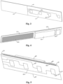
Fig. 10 is a schematic structural diagram of a housing provided by an embodiment of the present application; -
Fig. 11 is a partially enlarged schematic structural diagram of a segmented portion of a housing provided by an embodiment of the present application; -
Fig. 12 is a schematic structural diagram in which an antenna device is provided on a segmented portion of the housing shown inFig. 11 ; -
Fig. 13 is a schematic diagram of the structure shown inFig. 12 from another viewing angle; -
Fig. 14 is a partially enlarged schematic structural diagram of a segmented portion of a housing provided by another embodiment of the present application; -
Fig. 15 is a schematic diagram of the structure shown inFig. 14 from another viewing angle; -
Fig. 16 is a schematic structural diagram of an antenna device provided on a segmented portion of the housing shown inFig. 14 ; -
Fig. 17 is a partial enlarged structural schematic diagram of a segmented portion of a housing provided by another embodiment of the present application; -
Fig. 18 is a schematic diagram of the structure shown inFig. 17 from another viewing angle; -
Fig. 19 is a schematic structural diagram of an antenna device provided on a segmented portion of the housing shown inFig. 17 ; -
Fig. 20 is a schematic diagram of the structure shown inFig. 19 from another viewing angle; -
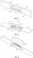
Fig. 21 is a partial enlarged structural schematic diagram of a segmented portion of a housing provided by another embodiment of the present application; -
Fig. 22 is a schematic diagram of the structure shown inFig. 21 from another viewing angle; -
Fig. 23 is a top view of a segmented portion of the housing shown inFig. 21 ; -
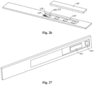
Fig. 24 is a partial enlarged structural schematic diagram of a segmented portion of a housing provided by another embodiment of the present application; -
Fig. 25 is a schematic diagram of the structure shown inFig. 24 from another viewing angle; -
Fig. 26 is a schematic structural diagram of an antenna device provided on a segmented portion of the housing shown inFig. 24 ; -
Fig. 27 is a schematic diagram of the structure shown inFig. 26 from another viewing angle. - Description of reference numerals:
- 10. antenna device; 20. housing;
- 100. substrate; 110. first section; 120. second section; 130. bent portion; 140. conductive isolation portion; 141. first isolation portion;
- 200. antenna module; 210. antenna unit;
- 300. integrated circuit;
- 400. connecting portion; 410. first segment; 420. second segment;
- 500. frame body; 501. segmented portion; 502. hollow space; 510. inner surface; 520. outer surface; 530. first groove; 531. first bottom wall surface; 532. first side wall surface; 533. clearance hole; 540. channel; 550. side surface; 551. first side surface; 552. second side surface; 560. second groove; 561. second bottom wall surface; 562. second side wall surface;
- 600. connector;
- 700. decorative cover;
- 800. metal shielding layer;
- Y. first direction; X. second direction; Z. third direction.
- Features and exemplary embodiments of various aspects of the present application will be described in detail below. In the detailed description below, many specific details are proposed to provide a comprehensive understanding of the present application. However, it is obvious to those skilled in the art that the present application can be implemented with no need for some of these specific details. The following description of the embodiments is only intended to provide a better understanding of the present application by illustrating examples of the present application. In the accompanying drawings and the following description, at least part of the known structures and technologies are not shown to avoid unnecessary obscuring the present application, and for clarity, the size of some structures may be exaggerated. In addition, features, structures or characteristics described below may be combined in one or more embodiments in any suitable manner.
- In the description of the present application, it should be noted that, unless otherwise specified, "the plurality of means more than two; the directions or positional relationships indicated by the terms "upper", "lower", "left", "right", "inner", "outer", etc. are only for the convenience of describing the present application and simplifying the description, and do not indicate or imply that the device or element referred to must have a specific direction, be constructed or operated in a specific direction, and therefore cannot be understood as limiting the present application. In addition, the terms "first", "second", etc. are only used for descriptive purposes and cannot be understood as indicating or implying relative importance.
- Directional words appearing in the following description are all directions shown in the figures, and do not limit the specific structure of the embodiments of the present application. In the description of the present application, it should also be noted that, unless otherwise clearly specified and limited, the terms "installation" and "connection" should be understood in a broad sense, for example, it can be a fixed connection, a detachable connection, or an integral connection; it can be directly connected or indirectly connected. For ordinary skilled in the field, the specific meanings of the above terms in this application can be understood according to the specific circumstances.
- In order to better understand the present application, an
antenna device 10, ahousing 20 and an electronic apparatus according to embodiments of the present application are described in detail below in conjunction withFigs. 1 and27 . - Please refer to
Figs. 1 and 2 together,Fig. 1 is a structural schematic diagram of anantenna device 10 provided by an embodiment of a first aspect of the present application;Fig. 2 is a structural schematic diagram of theantenna device 10 provided by an embodiment of the first aspect of the present application from another viewing angle. - As shown in
Fig. 1 and Fig. 2 , an embodiment of the first aspect of the present application provides anantenna device 10. Theantenna device 10 comprises asubstrate 100, anantenna module 200, anintegrated circuit 300, aconnector 600, and ametal shielding layer 800. Thesubstrate 100 comprises afirst section 110 and asecond section 120; theantenna module 200 is provided in thefirst section 110 and comprises two ormore antenna units 210 spaced apart on thefirst section 110; theintegrated circuit 300 is provided in thesecond section 120; the connectingportion 400 is provided in thesubstrate 100 and electrically connects theantenna unit 210 and theintegrated circuit 300; themetal shielding layer 800 is provided in thesubstrate 100, and an orthographic projection of the plurality ofantenna units 210 in a thickness direction of thefirst section 110 is located within an orthographic projection of themetal shielding layer 800 in the thickness direction. - In an
antenna device 10 provided in the present application, theantenna device 10 comprises asubstrate 100, anantenna module 200, anintegrated circuit 300, aconnector 600 and ametal shielding layer 800. Thefirst section 110 of thesubstrate 100 is configured to carry theantenna unit 210 of theantenna module 200, thesecond section 120 of thesubstrate 100 is configured to carry theintegrated circuit 300, and the connectingportion 400 connects theintegrated circuit 300 and theantenna unit 210, so that theintegrated circuit 300 can send a control signal to theantenna unit 210. Themetal shielding layer 800 is provided on thesubstrate 100, and the orthographic projection of the plurality ofantenna units 210 in the thickness direction of thefirst section 110 is located within the orthographic projection of themetal shielding layer 800 in the thickness direction. In one respect, themetal shielding layer 800 can improve the transmission of a signal sent by theantenna unit 210 to the inside of theantenna device 10, affecting its internal signal transmission. Besides themetal shielding layer 800 can reflect the signal out of theantenna device 10, thereby improving the wireless signal communication performance of theantenna device 10. - Alternatively, the
integrated circuit 300 may comprise a radio frequency integrated circuit and a battery management integrated circuit, the radio frequency integrated circuit is connected with theantenna unit 210 to transmit a radio frequency signal to theantenna unit 210. Alternatively, theintegrated circuit 300 may comprise only a radio frequency integrated circuit. - There are many ways to provide the
substrate 100. For example, thesubstrate 100 can be arigid substrate 100, which can be a structure such as glass or steel plate. Alternatively, the material of thesubstrate 100 comprises a flexible material such as polyimide, which allows thesubstrate 100 to readily change its shape according to the installation position, thereby simplifying the installation difficulty of theantenna device 10. - The
first section 110 and thesecond section 120 on thesubstrate 100 can be provided integrally or separately, and thefirst section 110 and thesecond section 120 can be provided in a stacked manner or distributed in sequence along a same direction. As an optional embodiment, as shown inFig. 1 and Fig. 2 , thesubstrate 100 further comprises abent portion 130, which is deformed to be bent and connects thefirst section 110 and thesecond section 120. Thefirst section 110 and thesecond section 120 are provided at intervals along the thickness direction. Thesubstrate 100 is generally U-shaped, so that thesubstrate 100 can break through metal shielding, for example, theantenna device 10 can be provided on a frame of an electronic apparatus, so that thesubstrate 100 covers an inner surface and an outer surface of the frame respectively and breaks through the metal shielding. And it can be ensured that a distance between theantenna unit 210 and theintegrated circuit 300 is closer, so that the intermediate loss is minimized, thereby improving the performance of theantenna device 10 and the quality of wireless communication of the antenna device of the electronic apparatus. - There are many ways to provide the
antenna unit 210. Optionally, theantenna unit 210 can be configured to send and receive millimeter wave antenna signals. Theantenna unit 210 can be formed by cutting a grid-like metal wiring. Alternatively, the material of theantenna unit 210 comprises a lighttransmitting conductive material such as indium tin oxide to improve the light transmittance of theantenna unit 210. More than twoantenna units 210 of theantenna module 200 can be provided independently with each other, or more than twoantenna units 210 can be electrically connected with each other through a connecting line. - There are many ways to provide the connecting
portion 400. The connectingportion 400 is configured to connect the signal line and electrically connect theantenna unit 210 and theintegrated circuit 300. A shape of the connectingportion 400 can be changed according to the positions of theantenna unit 210 and theintegrated circuit 300. As mentioned above, when thesubstrate 100 comprises thebent portion 130, the connectingportion 400 can electrically connect theantenna unit 210 and theintegrated circuit 300 via thebent portion 130. - Alternatively, the
metal shielding layer 800 may be formed by coating thesubstrate 100 with a metal material. - In some embodiments, as described above, the
first section 110 and thesecond section 120 may be spaced apart in the thickness direction of thefirst section 110, and themetal shielding layer 800 may be provided on thesecond section 120. Therefore, a distance between theantenna unit 210 on thefirst section 110 and themetal shielding layer 800 is increased, thereby improving the wireless signal transmission performance of theantenna unit 210. - There are many ways to provide the position of the
metal shielding layer 800 on thesecond section 120. Themetal shielding layer 800 can be provided on a surface of thesecond section 120 facing or away from thefirst section 110. Themetal shielding layer 800 and theintegrated circuit 300 can be provide on a same surface of thesecond section 120. Or, alternatively, themetal shielding layer 800 and theintegrated circuit 300 are separately provide on two surfaces of thesecond section 120 opposite to each other in the thickness direction, so that projections of themetal shielding layer 800 and theintegrated circuit 300 in the thickness direction can overlap, so that themetal shielding layer 800 and theintegrated circuit 300 can be provide on thesecond section 120 of smaller size at the same time, thereby reducing the overall volume of theantenna device 10. - Alternatively, the
metal shielding layer 800 is provided on a surface of thesecond section 120 facing thefirst section 110, and theintegrated circuit 300 is provided on a surface of thesecond section 120 away from thefirst section 110. So that theintegrated circuit 300 can be exposed to facilitate the electrical connection between theintegrated circuit 300 and theantenna unit 210. - In other embodiments, as shown in
Fig. 3 and Fig. 4 , thefirst section 110 and thesecond section 120 are sequentially distributed along the length direction of thefirst section 110, and themetal shielding layer 800 is provided in thefirst section 110. - In these embodiments, the
first section 110 and thesecond section 120 are provided side by side in sequence, and themetal shielding layer 800 and theantenna unit 210 are both provided in thefirst section 110, so that projections of themetal shielding layer 800 and theantenna unit 210 along the thickness direction of thefirst section 110 can overlap. - Alternatively, the
antenna unit 210 and themetal shielding layer 800 are provided on two opposite surfaces of thefirst section 110 in the thickness direction to increase the distance between themetal shielding layer 800 and theantenna unit 210 and improve the performance of theantenna unit 210 in transmitting wireless signals. - Alternatively, as shown in
Figs. 1 and 2 , andFigs. 5 to 8 , thesubstrate 100 may further comprise abent portion 130 connecting thefirst section 110 and thesecond section 120, thefirst section 110, thesecond section 120 and thebent portion 130 are integrally provided, one end of the connectingportion 400 is connected with theantenna unit 210, and the other end extends to theintegrated circuit 300 via thebent portion 130 to electrically connect theantenna unit 210 and theintegrated circuit 300. The connectingportion 400 is connected between theantenna unit 210 and theintegrated circuit 300 via thebent portion 130 to realize transmission of signals between theintegrated circuit 300 and theantenna unit 210. - There are many positions for providing the
bent portion 130. As shown inFigs. 1 and 2 , thebent portion 130 can be provided on a side of thefirst section 110 in a width direction. Alternatively, as shown inFigs. 5 and6 , thebent portion 130 can be provided on a side of thefirst section 110 in the second direction X. The size of thebent portion 130 can be the same as or different from the size of thefirst section 110. As shown inFigs. 1 and 2 , thebent portion 130 is provided on a side of thefirst section 110 in the third direction Z, and the length of thebent portion 130 is less than the length of thefirst section 110. Alternatively, as shown inFigs. 7 and8 , the length of thebent portion 130 is equal to the length of thefirst section 110. - In other embodiments, the
first section 110 and thesecond section 120 can be separately provided, and the connectingportion 400 comprises afirst segment 410 provided in thefirst section 110 and electrically connected with theantenna unit 210, and asecond segment 420 provided in thesecond section 120 and electrically connected with theintegrated circuit 300. Thefirst segment 410 and thesecond segment 420 are bound and connected, which can increase the freedom of material selection, so as to reduce the size of theantenna module 200, reduce the cost, and improve the reliability of the performance of theline module 200. Or thefirst segment 410 and thesecond segment 420 are electrically connected with each other by means of a connector. For example, thefirst segment 410 and thesecond segment 420 are connected with each other by plugging in through a plug connector, which is convenient for maintenance and replacement. - In some optional embodiments, as shown in
Fig. 9 , theantenna device 10 further comprises aconductive isolation portion 140, which is provided in thefirst section 110 and between twoadjacent antenna units 210. Theconductive isolation portion 140 can be provided to increase the isolation between twoadjacent antenna units 210 and improve the performance of theantenna unit 210. - Optionally, the
conductive isolation portion 140 may be provided on the surface of thefirst section 110, and/or theconductive isolation portion 140 may be provided in thefirst section 110. As long as theconductive isolation portion 140 is located between twoadjacent antenna units 210, it will suffice. - Optionally, the
conductive isolation portion 140 comprises afirst isolation portion 141 provided on the surface of thefirst section 110 and a second isolation portion 142 provided in thefirst section 110. Thefirst isolation portion 141 and the second isolation portion 142 are connected with each other. By providing thefirst isolation portion 141 located on the surface of thefirst section 110 and the second isolation portion 142 located in thefirst section 110, isolation betweenadjacent antenna units 210 can be increased, and the problem of signal interference between twoadjacent antenna units 210 can be better improved. - Alternatively, surfaces of the
first section 110 facing toward and away from thesecond section 120 are both provided with a firstconductive isolation portion 141, that is, thefirst isolation portion 141 is provided on two opposite surfaces of thefirst section 110, and the second isolation portion 142 is connected with thefirst isolation portion 141 located on two opposite surfaces of thefirst section 110, thereby further increasing the isolation betweenadjacent antenna units 210, better improving the problem of antenna mutual coupling between twoadjacent antenna units 210, and thereby improving the performance of wireless communication. - Optionally, when the
antenna module 200 is provided in the housing of the electronic apparatus, the firstconductive isolation portion 141 of thefirst section 110 facing the surface of thesecond section 120 can be in contact and connected with the frame of the housing to better improve the problem of antenna mutual coupling between twoadjacent antenna units 210, thereby improving the performance of wireless communication. - In any of the above embodiments, there are many ways to provide the
antenna module 200. Theantenna module 200 can be configured to send and receive wireless signals of various frequency bands; for example, the wireless module is configured to send and receive millimeter wave wireless signals. - As shown in
Figs. 10 to 13 , an embodiment of the second aspect of the present application further provides ahousing 20 of an electronic apparatus, the electronic apparatus comprises anantenna device 10, and theantenna device 10 comprises a plurality ofantenna units 210. Alternatively, theantenna device 10 may be theantenna device 10 in any of the above embodiments. Theantenna device 10 may also be theantenna device 10 in other embodiments. The present application is illustrated by taking theantenna device 10 provided by any of the above first embodiments as an example. - Alternatively, the
housing 20 comprises aframe body 500, theframe body 500 encloses ahollow space 502, and theframe body 500 comprises asegmented portion 501, wherein thesegmented portion 501 has aclearance hole 533 provided penetrating through, and theclearance hole 533 is configured to provide clearance for a plurality ofantenna units 210. - In these optional embodiments, the
frame body 500 of thehousing 20 encloses ahollow space 502, so that components of the electronic apparatus can be provided in thehollow space 502. Thesegmented portion 501 of theframe body 500 comprises aclearance hole 533 provided penetrating through, and theclearance hole 533 can accommodate the plurality ofantenna units 210. For example, when theantenna device 10 is the above-mentionedantenna device 10, theclearance hole 533 can accommodate thesubstrate 100. Since theclearance hole 533 penetrates through thesegmented portion 501, a distance between theantenna unit 210 and themetal shielding layer 800 can be increased, thereby improving the wireless communication performance of theantenna device 10. -
Fig. 10 is a structural schematic diagram of a frame of ahousing 20 provided in an embodiment of the present application,Fig. 11 is a structural schematic diagram of asegmented portion 501 of a frame of ahousing 20 provided in an embodiment of the present application,Fig. 12 is a structural schematic diagram when theantenna device 10 is provide on thesegmented portion 501, andFig. 13 is a structural schematic diagram when theantenna device 10 is provide on thesegmented portion 501 from another viewing angle. - The
frame body 500 may be a middle frame of the electronic apparatus. A material of theframe body 500 may comprise a metal material to improve the structural strength of theframe body 500. For example, theframe body 500 comprises a plurality ofsegmented portions 501, and the plurality ofsegmented portions 501 are connected end to end to enclose ahollow space 502. The plurality ofsegmented portions 501 comprise two first segmented portions spaced apart along a first direction Y and two second segmented portions spaced apart along a second direction X, and the two first segmented portions and the two second segmented portions are alternately enclosed to form a hollow portion. - There are many ways to provide the
clearance hole 533. As shown inFigs. 12 and 13 , theclearance hole 533 is formed by extending along a spacing direction of the plurality ofantenna units 210, and thesame clearance hole 533 is configured to correspond to the plurality ofantenna units 210. The plurality ofantenna units 210 are provided corresponding to thesame clearance hole 533, which can simplify the shape of the frame and the installation process of the plurality ofantenna units 210, and improve the assembly efficiency of theantenna device 10. - Alternatively, when the
antenna device 10 is provided in the first segmented portion, the plurality ofantenna units 210 may be spaced apart along the second direction X, and theclearance hole 533 may be extended along the second direction X, where the second direction X is a length direction of the first segmented portion, that is, the length direction of thefirst section 110. When theantenna device 10 is provided in the second segmented portion, the plurality ofantenna units 210 may be spaced apart along the first direction Y, and theclearance hole 533 may be extended along the first direction Y, where the first direction Y is a length direction of the second segmented portion, that is, the length direction of thefirst section 110. - In another embodiment, as shown in
Figs. 14 to 16 , a plurality of theclearance holes 533 are provided at intervals, and theclearance holes 533 each are configured to correspond to theantenna units 210, respectively. The plurality ofclearance holes 533 are provided at intervals, which can improve the structural strength of the frame. Alternatively, theclearance holes 533 and theantenna units 210 are provided in one-to-one correspondence, so that eachantenna unit 210 is correspondingly provided with aclearance hole 533. - In some embodiments, as shown in
Figs. 17 to 20 , thesegmented portion 501 comprises aninner surface 510 facing thehollow space 502 and anouter surface 520 away from thehollow space 502, and theinner surface 510 and/or theouter surface 520 are recessed to form afirst groove 530, and theclearance hole 533 is provided in thefirst groove 530. - In these embodiments, a
first groove 530 is formed on a portion of thesegmented portion 501 of theframe body 500, and thefirst groove 530 can accommodate a plurality ofantenna units 210. For example, when theantenna device 10 is the above-mentionedantenna device 10, thefirst groove 530 can accommodate thesubstrate 100, and a plurality of theantenna units 210 are provided at intervals on thesubstrate 100. The plurality ofantenna units 210 are accommodated in a samefirst groove 530, which can improve the installation process of the plurality ofantenna units 210 and the assembly efficiency of theantenna device 10. Theclearance hole 533 in thefirst groove 530 can be provided corresponding to a single or a plurality ofantenna units 210. - In addition, by providing the
first groove 530 on theinner surface 510 and/or theouter surface 520 of thesegmented portion 501, it is possible to improve the problem that theouter surface 520 of the frame is uneven when thesubstrate 100 is directly provided on the surface of thesegmented portion 501, and it is also possible to improve the problem that thesubstrate 100 is unstable and difficult to fix when it is directly provided in theclearance hole 533. - Optionally, the
frame body 500 may be provided with a plurality offirst grooves 530, each of which is configured to accommodate a plurality of antenna units. The plurality offirst grooves 530 are provided at different positions of theframe body 500, so that the plurality ofantenna module 200 will not be covered at the same time when the mobile terminal is in a horizontal screen, a vertical screen, etc. It can also reduce the blind area of wireless signals and achieve better communication quality. - The
first groove 530 has a firstbottom wall surface 531, and theclearance hole 533 is provide on the firstbottom wall surface 531, and the size of theclearance hole 533 is smaller than the size of the firstbottom wall surface 531, so that thesubstrate 100 can be in contact and connected with at least a portion of the firstbottom wall surface 531 to improve the stability of the position of thesubstrate 100 and thefirst groove 530. - Alternatively, the
inner surface 510 and/or theouter surface 520 is further recessed to form asecond groove 560, and thesecond groove 560 is configured to accommodate theintegrated circuit 300. Thesecond groove 560 can provide limit for theintegrated circuit 300 to ensure the stability of the position of theintegrated circuit 300. For example, thesecond groove 560 is configured to accommodate thesecond section 120 and theintegrated circuit 300 provided in thesecond section 120, thesecond groove 560 comprises a second bottom wall surface 561, and thesecond section 120 and the second bottom wall surface 561 are in contact and connected. - Alternatively, the
clearance hole 533 penetrates through the firstbottom wall surface 531 and the second bottom wall surface 561. - In some optional embodiments, as described above, when the
first section 110 and thesecond section 120 of thesubstrate 100 are distributed at intervals, one of thefirst groove 530 and thesecond groove 560 can be provided on theouter surface 520, and the other can be provided on theinner surface 530. Or thefirst section 110 and thesecond section 120 can be provided on theinner surface 510 and theouter surface 520 respectively, so that one of theantenna unit 210 and theintegrated circuit 300 is provided on theinner surface 510, and the other is provided on theouter surface 520. - In these embodiments, alternatively, the
first groove 530 is located on theouter surface 520, thesecond groove 560 is located on theinner surface 510, thefirst section 110 may be located in thefirst groove 530, and thesecond section 120 may be located in thesecond groove 560, so that theantenna unit 210 is located on theouter surface 520, which can improve the effect of the frame blocking theantenna unit 210 and affecting its wireless signal transmission, and theintegrated circuit 300 is located on theinner surface 510, so that thesegmented portion 501 can provide protection for it. - Optionally, as described above, the
first groove 530 has a firstbottom wall surface 531, and theantenna unit 210 is provided on a side of thefirst section 110 away from the firstbottom wall surface 531, so as to improve the shielding of theantenna unit 210 by thefirst section 110. And/or, as described above, thesecond groove 560 has a second bottom wall surface 561, and theintegrated circuit 300 is provided on a side of thesecond section 120 away from the second bottom wall surface 561. Optionally, when thefirst groove 530 is provided on theouter surface 520 and thesecond groove 560 is provided on theinner surface 510, there are a plurality of ways for the connectingportion 400 to connect theantenna unit 210 and theintegrated circuit 300. As described above, the substrate may comprise abent portion 130, and the connectingportion 400 may electrically connect theantenna unit 210 and theintegrated circuit 300 via thebent portion 130. - In other embodiments, as shown in
Figs. 11 to 16 , thesegmented portion 501 comprises achannel 540 that penetrates through theinner surface 510 and theouter surface 520, thechannel 540, thefirst groove 530 and thesecond groove 560 are communicated with each other. - In these optional embodiments, the
segmented portion 501 further comprises achannel 540, which is communicated with thefirst groove 530, so that the connectingportion 400 can be connected with theantenna unit 210 located in thefirst groove 530 via thechannel 540, thereby facilitating the electrical connection between theantenna unit 210 and theintegrated circuit 300. - The
channel 540 may be provided in various positions. For example, as shown inFigs. 11 to 16 , thesegmented portion 501 further comprises aside surface 550 connecting theinner surface 510 and theouter surface 520, and thechannel 540 may be formed by recessing of theside surface 550. When thesubstrate 100 comprises thefirst section 110, thesecond section 120, and thebent portion 130, thebent portion 130 may be located in thechannel 540 to improve the problem that thebent portion 130 protrudes too high from theside surface 550. - In other embodiments, as shown in
Figs. 17 to 23 , thefirst groove 530 further comprises a firstside wall surface 532 connected with the periphery of the firstbottom wall surface 531, and thechannel 540 is communicated with the firstside wall surface 532 or the firstbottom wall surface 531. When thesubstrate 100 comprises afirst section 110 and asecond section 120 that are separately provided, thefirst section 110 and thesecond section 120 can be separately provided on theinner surface 510 and theouter surface 520, and the connectingportion 400 connects theantenna unit 210 and theintegrated circuit 300 via thechannel 540 that is connected with the firstside wall surface 532 or the firstbottom wall surface 531. - Alternatively, as described above, as shown in
Figs. 24 to 27 , when thefirst section 110 and thesecond section 120 are provided side by side, thefirst groove 530 and thesecond groove 560 can both be provided on theinner surface 510, so that theantenna unit 210 and theintegrated circuit 300 can both be protected by thesegmented portion 501. - Alternatively, the
housing 20 may further comprise adecorative cover 700, and thedecorative cover 700 may be provided on thefirst groove 530. Thedecorative cover 700 may have the effects of being aesthetically pleasing, wear-resistant, waterproof, dust-proof, and anti-aging. - Alternatively, the material of the frame may comprise metal material to make the frame have sufficient structural strength. Alternatively, the material of the
decorative cover 700 may comprise insulating material to improve the signal transmission of theantenna unit 210 in thefirst groove 530 when thedecorative cover 700 is covered on thefirst groove 530. - Alternatively, the
decorative cover 700 is covered on thefirst groove 530, the shapes of thedecorative cover 700 and thefirst groove 530 match, the area and shape of thedecorative cover 700 and the firstbottom wall surface 531 are the same, and thedecorative cover 700 and thefirst side wall 532 are in contact and connected with each other. Alternatively, when thefirst groove 530 is provide on theouter surface 520, thedecorative cover 700 is align with theouter surface 520 to ensure the flatness of theouter surface 520 of theframe body 500. When thefirst groove 530 is provide on theinner surface 510, thedecorative cover 700 can also be align with theinner surface 510. - As described above, when the
channel 540 is communicated with the firstside wall surface 532 or the firstbottom wall surface 531, the shape of thehousing 700 may not be irregular, so it is often more friendly to the aesthetic design of the appearance and the aesthetic taste of most consumers. - Optionally, the
decorative cover 700 can further be covered on thesecond groove 560, and the shapes of thedecorative cover 700 and thesecond groove 560 match. Thesecond groove 560 comprises a second bottom wall surface 561 and a secondside wall surface 562 connected with the periphery of the second bottom wall surface 561. Thedecorative cover 700 and the second bottom wall surface 561 have the same area and shape, and thedecorative cover 700 and the secondside wall surface 562 are in contact with each other. Optionally, when thesecond groove 560 is provide on theinner surface 510, thedecorative cover 700 is align with theinner surface 510 to ensure the flatness of theinner surface 510 of theframe body 500. When thesecond groove 560 is provide on theouter surface 520, thedecorative cover 700 can also be flush with theouter surface 520. - Optionally, when the
antenna device 10 comprises aconductive isolation portion 140, a projection of theconductive isolation portion 140 along the thickness direction of thefirst section 110 and a projection of theclearance hole 533 along the thickness direction of thefirst section 110 are staggered. For example, the projection of theconductive isolation portion 140 along the first direction Y is located between the projections of twoadjacent clearance holes 533 along the first direction Y. Alternatively, when theconductive isolation portion 140 is provided on a side of thefirst section 110 facing thesecond section 120, theconductive isolation portion 140 located on the side of thefirst section 110 facing thesecond section 120 can be electrically connected with thesegmented portion 501 to further improve isolation between the twoadjacent antenna units 210, so as to achieve better antenna performance and better wireless communication quality. - An embodiment of a third aspect of the present application further provides an electronic apparatus, comprising the
antenna device 10 of any of the above-mentioned embodiments of the first aspect and any of the above-mentionedhousing 20 of the second aspect embodiments, wherein an orthographic projection of at least one of theantenna units 210 along the thickness direction of thefirst section 110 is located within an orthographic projection of theclearance hole 533 along the thickness direction of thefirst section 110. - As shown in
Figs. 1 to 27 , the electronic apparatus in the embodiments of the present application comprise but are not limited to mobile phones, personal digital assistants (Personal Digital Assistant, referred to as: PDA), tablet computers, e-books, televisions, access control, smart fixed phones, consoles and other devices with display functions. - There are many ways to set the thickness direction of the
first section 110. When the antenna device is provide in the first segmented portion, the thickness direction of thefirst section 110 can be the first direction Y. When the antenna device is provide in the second segmented portion, the thickness direction of thefirst section 110 can be the second direction X. - Alternatively, the
metal shielding layer 800 of the antenna device may be in contact with and connected with thesegmented portion 501 to achieve grounding of the antenna device. - In these optional embodiments, the
frame body 500 of thehousing 20 encloses ahollow space 502, so that the components of the electronic apparatus can be provided in thehollow space 502. Thesegmented portion 501 of theframe body 500 comprises aclearance hole 533 provided penetrating through, and theclearance hole 533 can accommodate a plurality ofantenna units 210. An orthographic projection of at least oneantenna unit 210 along the thickness direction of thefirst section 110 is located within an orthographic projection of theclearance hole 533 along the thickness direction of thefirst section 110, which can increase the distance between theantenna unit 210 and themetal shielding layer 800, thereby improving the wireless communication performance of theantenna device 10. - In some optional embodiments, the plurality of
antenna units 210 are provided at intervals along the length direction of thesegmented portion 501, theclearance holes 533 are formed by extending along the length direction, and the orthographic projection of the plurality ofantenna units 210 along the thickness direction of thefirst section 110 are located within the orthographic projections of thesame clearance hole 533 along the thickness direction of thefirst section 110. The plurality ofantenna units 210 are provided corresponding to asame clearance hole 533, which can simplify the shape of the frame and the installation process of the plurality ofantenna units 210, and improve the assembly efficiency of theantenna device 10. - Alternatively, as described above, when the
antenna device 10 is provided in the first segmented portion, the plurality ofantenna units 210 may be distributed at intervals along the second direction X, theclearance holes 533 may be extended along the second direction X, and the second direction X is the length direction of the first segmented portion. When theantenna device 10 is provided in the second segmented portion, the plurality ofantenna units 210 may be distributed at intervals along the first direction Y, theclearance holes 533 may be extended along the first direction Y, and the first direction Y is the length direction of the second segmented portion. - In another embodiment, a plurality of
clearance holes 533 are provided at intervals, and the orthographic projection of eachantenna unit 210 along the thickness direction of thefirst section 110 is located within the orthographic projection of eachclearance hole 533 along the thickness direction of thefirst section 110. Moreover, eachantenna unit 210 is provided corresponding to eachclearance hole 533, which can improve the performance of theantenna unit 210 and the structural strength of the frame. - In some optional embodiments, as described above, the
inner surface 510 and/or theouter surface 520 is recessed to form afirst groove 530, theclearance hole 533 is provided in thefirst groove 530, and thefirst section 110 is located in thefirst groove 530. Thus, the plurality ofantenna units 210 provided in thefirst section 110 can be located in a samefirst groove 530, thereby simplifying the installation of theantenna device 10. - In some optional embodiments, as described above, the
housing 20 further comprises asecond groove 560 formed by recessing of theinner surface 510, and thesecond section 120 is located in thesecond groove 560. Thesecond groove 560 can provide limit for theintegrated circuit 300 on thesecond section 120 to ensure the stability of the position of theintegrated circuit 300. - Alternatively, the
first groove 530 is provided on theouter surface 520, and thesecond section 120 is provided on theinner surface 510. So that theantenna unit 210 located in thefirst groove 530 is located on theouter surface 520, which can improve the effect of the frame blocking theantenna unit 210 and affecting the transmission of its wireless signal, and theintegrated circuit 300 located in thesecond groove 560 is located on theinner surface 510, so that thesegmented portion 501 can provide protection for it. - Alternatively, the
segmented portion 501 comprises achannel 540 that penetrates through theinner surface 510 and theouter surface 520, thechannel 540 and thefirst groove 530 are communicated with each other, and the connectingportion 400 electrically connects theantenna unit 210 and theintegrated circuit 300 via thechannel 540. The connectingportion 400 can be connected with theantenna unit 210 located in thefirst groove 530 via thechannel 540, so as to facilitate the electrical connection between theantenna unit 210 and theintegrated circuit 300. - Alternatively, the
segmented portion 501 further comprises a first side surface 551 and asecond side surface 552 connected theinner surface 510 and theouter surface 520 and provided opposite to each other, and thechannel 540 is formed by recessing of the first side surface 551. A top surface of the connectingportion 400 away from thesecond side surface 552 is coplanar with the first side surface 551, or a top surface of the connectingportion 400 away from thesecond side surface 552 is located on a side of the first side surface 551 facing thesecond side surface 552. This improves the problem of theuneven side surface 550. - Alternatively, the
antenna device 10 further comprises aconnector 600 electrically connected with theintegrated circuit 300, and theconnector 600 and theintegrated circuit 300 are both provided in thesecond section 120. This reduces the distance between theconnector 600 and theintegrated circuit 300, and facilitates the connection between theconnector 600 and theintegrated circuit 300. Theintegrated circuit 300 can be electrically connected with outside through theconnector 600, for example, theintegrated circuit 300 can be electrically connected with a mainboard of the electronic apparatus through theconnector 600. - Alternatively, the plurality of
antenna units 210 are distributed at intervals along the extension direction of thesegmented portion 501, so thatmore antenna units 210 can be provided on thesegmented portion 501. The extension direction of thesegmented portion 501 is the length direction of thesegmented portion 501. - Alternatively, the
integrated circuit 300 and theconnector 600 are distributed at intervals along the extension direction of thesegmented portion 501. Thesegmented portion 501 has a larger size in its extension direction, which can leave more space for theintegrated circuit 300 and theconnector 600. - Alternatively, the
first section 110 and thesecond section 120 are distributed in sequence along the length direction of thefirst section 110, thefirst groove 530 and thesecond groove 560 are both provided on theinner surface 510 and distributed in sequence along the length direction, a plurality ofantenna units 210 are provided on a side of thefirst section 110 away from thehollow space 502 and exposed by theclearance hole 533, and themetal shielding layer 800 is provided on a side of thefirst section 110 facing thehollow space 502. - In these embodiments, the
metal shielding layer 800 and theantenna unit 210 are respectively provided on two sides of thefirst section 110, which can increase the distance between themetal shielding layer 800 and theantenna unit 210 and improve the wireless communication performance of theantenna unit 210. Themetal shielding layer 800 is located on the side of thefirst section 110 facing thehollow space 502, and theantenna unit 210 is located on the side of thefirst section 110 away from thehollow space 502, which can prevent themetal shielding layer 800 from shielding theantenna unit 210 and affecting its signal transmission. - Although the present application has been described with reference to preferred embodiments, various modifications may be made thereto and parts thereof may be replaced with equivalents without departing from the scope of the present application. In particular, the various technical features mentioned in the various embodiments may be combined in any manner as long as there are no structural conflicts. The present application is not limited to the specific embodiments disclosed herein, but comprises all technical solutions falling within the scope of the claims.
Claims (15)
- A housing of an electronic apparatus that comprises an antenna device (10) including a plurality of antenna units (210), the housing comprising:a frame body (500), enclosing a hollow space (502) and comprising a segmented portion (501),wherein the segmented portion (501) comprises a clearance hole (533) that is provided penetrating through the segmented portion (501), and the clearance hole (533) is configured to provide clearance for the plurality of antenna units (210).
- The housing of claim 1, whereinthe clearance hole (533) is formed by extending along the spacing direction of the plurality of antenna units (210), which clearance hole (533) is configured to correspond to the plurality of antenna units (210); ora plurality of the clearance holes (533) are provided at intervals, and the clearance holes (533) are configured to correspond to the antenna units (210), respectively;preferably, a plurality of the clearance holes (533) are provided at intervals, and the clearance holes (533) are provided in one-to-one correspondence with the antenna units (210).
- The housing of claim 1 or 2, wherein the segmented portion (501) comprises an inner surface (510) facing the hollow space (502) and an outer surface (520) away from the hollow space (502), the inner surface (510) and/or the outer surface (520) are recessed to form a first groove (530), and the clearance hole (533) is provided in the first groove (530);preferably, the inner surface (510) and/or the outer surface (520) are recessed to form a second groove (560) configured to accommodate the integrated circuit (300) of the antenna device (10);preferably, one of the first groove (530) and the second groove (560) is provided on the outer surface (520), and the other is provided on the inner surface (510);alternatively, the first groove (530) and the second groove (560) are located on the inner surface (510);preferably, the first groove (530) is provided on the outer surface (520), the second groove (560) is provided on the inner surface (510), the segmented portion (501) comprises a channel (540) provided penetrating through the inner surface (510) and the outer surface (520), and the channel (540) is communicated with the first groove (530) and the second groove (560);preferably, the first groove (530) comprises a first bottom wall surface (531) and a first side wall surface (562) connected with a periphery of the first bottom wall surface (531), and the channel (540) is communicated with the first side wall surface (562) or the first bottom wall surface (531);alternatively, the segmented portion (501) further comprises a side surface (550) connecting the inner surface (510) and the outer surface (520), and the channel (540) is formed by recessing the side surface (550);preferably, the housing further comprises a decorative cover (700) fitting on the first groove (530) and/or the second groove (560).
- An electronic apparatus, comprising an antenna device (10) and the housing of any one of claims 1 to 3, the antenna device (10) comprising:a substrate (100), comprising a first section (110) and a second section (120);an antenna module (200), provided on the first section (110) and comprising two or more antenna units (210) distributed at intervals on the first section (110);an integrated circuit (300), provided on the second section (120);a connecting portion (400), provided on the substrate (100) and electrically connecting the antenna units (210) and the integrated circuit (300),wherein an orthographic projection of at least one of the antenna units (210) along a thickness direction is located within an orthographic projection of the clearance hole (533) along the thickness direction.
- The electronic apparatus of claim 4, wherein the antenna device (10) further comprises a metal shielding layer (800), provided on the substrate (100), orthographic projections of a plurality of the antenna units (210) in a thickness direction of the first section (110) being located within an orthographic projection of the metal shielding layer (800) in the thickness direction;the first section (110) and the second section (120) are distributed at intervals along the thickness direction, and the metal shielding layer (800) is provided on the second section (120);preferably, the metal shielding layer (800) and the integrated circuit (300) are provided on two surfaces of the second section (120) opposite to each other in the thickness direction, respectively;preferably, the metal shielding layer (800) is provided on a surface of the second section (120) facing the first section (110), and the integrated circuit (300) is provided on a surface of the second section (120) away from the first section (110).
- The electronic apparatus of claim 4 or 5, wherein the first section (110) and the second section (120) are sequentially distributed along a length direction of the first section (110), and the metal shielding layer (800) is provided on the first section (110);
preferably, the antenna unit (210) and the metal shielding layer (800) are provided on two surfaces of the first section (110) opposite to each other in the thickness direction, respectively. - The electronic apparatus of any one of claims 4 to 6, wherein the substrate further comprises a bent portion (130) connecting the first section (110) and the second section (120), the first section (110), the second section (120) and the bent portion (130) being integrally provided, one end of the connecting portion (400) being connected with the antenna unit (210), and the other end of the connecting portion (400) extending to the integrated circuit (300) via the bent portion (130) to electrically connect the antenna unit (210) and the integrated circuit (300); or
the first section (110) and the second section (120) are separately provided, and the connecting section comprises a first segment (410) provided on the first section (110) and electrically connected with the antenna unit (210), and a second segment (420) provided on the second section (120) and electrically connected with the integrated circuit (300), the first segment (410) and the second segment (420) being bound and connected, or the first segment (410) and the second segment (420) being electrically connected with each other via a connector (600). - The electronic apparatus of any one of claims 4 to 7, further comprising a conductive isolation portion (140) provided on the first section (110) and located between two adjacent ones of the antenna units (210);preferably, the conductive isolation portion (140) being provided on a surface of the first section (110), and/or the conductive isolation portion (140) being provided inside the first section (110);preferably, the conductive isolation portion (140) comprising a first isolation portion (141) provided on a surface of the first section (110) and a second isolation portion (142) provided inside the first section (110), the first isolation portion (141) and the second isolation portion (142) being connected with each other;preferably, the first isolating portion (141) being provided on two opposite surfaces of the first section (110), and the second isolating portion (142) being connected with the first isolating portions (141) located on the two opposite surfaces of the first section (110).
- The electronic apparatus of any one of claims 4 to 8, wherein the plurality of antenna units (210) are provided at intervals along the length direction of the segmented portion (501), the clearance hole (533) is formed by extending along the length direction, and orthographic projections of the plurality of antenna units (210) along the thickness direction are located within an orthographic projection of the same clearance hole (533) along the thickness direction.
- The electronic apparatus of any one of claims 4 to 9, wherein a plurality of the clearance holes (533) are provided at intervals, and orthographic projections of the antenna units (210) along the thickness direction are located within orthographic projections of the clearance holes (533) along the thickness direction, respectively.
- The electronic apparatus of any one of claims 4 to 10, wherein the segmented portion (501) comprises an inner surface (510) facing the hollow space (502) and an outer surface (520) away from the hollow space (502), the inner surface and/or the outer surface (520) are recessed to form a first groove (530), the clearance hole (533) is provided in the first groove (530), and the first section (110) is located in the first groove (530);preferably, the housing further comprises a second groove (560) formed by recessing the inner surface (510), and the second section (120) is located in the second groove (560);preferably, the first groove (530) is provided on the outer surface (520), and the second section (120) is provided on the inner surface (510).
- The electronic apparatus of any one of claims 4 to 11, wherein the first groove (530) has a first bottom wall surface, and the antenna unit (210) is provided on a side of the first section (110) away from the first bottom wall surface; and/or the second groove (560) has a second bottom wall surface, and the integrated circuit (300) is provided on a side of the second section (120) away from the second bottom wall surface.
- The electronic apparatus of any one of claims 4 to 12, wherein the segmented portion (501) comprises a channel (540) provided penetrating through the inner surface (510) and the outer surface (520), the channel (540) and the first groove (530) are communicated with each other, and the connecting portion (400) is electrically connected with the antenna unit (210) and the integrated circuit (300) via the channel (540);
preferably, the segmented portion (501) further comprises a first side surface and a second side surface which are connected with the inner surface (510) and the outer surface (520) and are provided opposite to each other, the channel (540) is formed by recessing the first side surface, a top surface of the connecting portion (400) away from the second side surface is coplanar with the first side surface, or a top surface of the connecting portion (400) away from the second side surface is located on a side of the first side surface facing the second side surface. - The electronic apparatus of any one of claims 4 to 13, the antenna device further comprises a connector electrically connected with the integrated circuit (300), and the connector and the integrated circuit (300) both are provided in the second section (120);
preferably, the plurality of antenna units (210) are distributed at intervals along an extension direction of the segmented portion (501), and/or the integrated circuit (300) and the connector are distributed at intervals along the extension direction of the segmented portion (501). - The electronic apparatus of any one of claims 4 to 14, the first section (110) and the second section (120) are sequentially distributed along the length direction of the first section (110), the first groove (530) and the second groove (560) both are provided on the inner surface (510) and sequentially distributed along the length direction, the plurality of antenna units (210) are provided on a side of the first section (110) away from the hollow space (502) and exposed by the clearance hole (533), and metal shielding layer (800) is provided on a side of the first section (110) facing the hollow space (502).
Applications Claiming Priority (1)
| Application Number | Priority Date | Filing Date | Title |
|---|---|---|---|
| CN202311542540.8A CN117766976B (en) | 2023-11-17 | 2023-11-17 | Antenna device, housing, and electronic apparatus |
Publications (1)
| Publication Number | Publication Date |
|---|---|
| EP4557512A1 true EP4557512A1 (en) | 2025-05-21 |
Family
ID=90320976
Family Applications (1)
| Application Number | Title | Priority Date | Filing Date |
|---|---|---|---|
| EP24213261.1A Pending EP4557512A1 (en) | 2023-11-17 | 2024-11-15 | Antenna device, housing and electronic apparatus |
Country Status (5)
| Country | Link |
|---|---|
| US (1) | US20250070451A1 (en) |
| EP (1) | EP4557512A1 (en) |
| JP (1) | JP2025082844A (en) |
| KR (1) | KR20240169563A (en) |
| CN (1) | CN117766976B (en) |
Citations (4)
| Publication number | Priority date | Publication date | Assignee | Title |
|---|---|---|---|---|
| US20170222312A1 (en) * | 2014-10-16 | 2017-08-03 | Murata Manufacturing Co., Ltd. | Antenna module accommodation structure |
| US20210320408A1 (en) * | 2018-12-28 | 2021-10-14 | Vivo Mobile Communication Co., Ltd. | Antenna structure and high-frequency multi-band wireless communication terminal |
| US20220085501A1 (en) * | 2019-05-22 | 2022-03-17 | Vivo Mobile Communication Co.,Ltd. | Antenna unit and terminal device |
| US20220109228A1 (en) * | 2021-11-16 | 2022-04-07 | Etheta Communication Technology (Shenzhen) Co., Ltd. | Antenna device and electronic apparatus |
Family Cites Families (7)
| Publication number | Priority date | Publication date | Assignee | Title |
|---|---|---|---|---|
| JP2006024817A (en) * | 2004-07-09 | 2006-01-26 | Matsushita Electric Ind Co Ltd | Semiconductor device |
| FR2885456A1 (en) * | 2005-05-03 | 2006-11-10 | Thomson Licensing Sa | Antenna device for e.g. airport, has transmission and reception antenna units integrated on rigid substrate, where wave transmitted by transmission antenna unit has polarization perpendicular to wave received by reception antenna units |
| WO2019163376A1 (en) * | 2018-02-22 | 2019-08-29 | 株式会社村田製作所 | Antenna module and communication device having same installed therein |
| CN108493587B (en) * | 2018-05-04 | 2020-03-10 | Oppo广东移动通信有限公司 | Shell assembly, antenna assembly and electronic equipment |
| CN109728405B (en) * | 2018-12-28 | 2022-03-01 | 维沃移动通信有限公司 | Antenna structure and high frequency wireless communication terminal |
| CN110854507B (en) * | 2019-11-21 | 2021-08-03 | Oppo广东移动通信有限公司 | Antenna package modules and electronic equipment |
| CN112216958B (en) * | 2020-09-30 | 2022-11-18 | 维沃移动通信有限公司 | Electronic device |
-
2023
- 2023-11-17 CN CN202311542540.8A patent/CN117766976B/en active Active
-
2024
- 2024-11-13 US US18/945,859 patent/US20250070451A1/en active Pending
- 2024-11-14 KR KR1020240161906A patent/KR20240169563A/en active Pending
- 2024-11-15 EP EP24213261.1A patent/EP4557512A1/en active Pending
- 2024-11-15 JP JP2024199923A patent/JP2025082844A/en active Pending
Patent Citations (4)
| Publication number | Priority date | Publication date | Assignee | Title |
|---|---|---|---|---|
| US20170222312A1 (en) * | 2014-10-16 | 2017-08-03 | Murata Manufacturing Co., Ltd. | Antenna module accommodation structure |
| US20210320408A1 (en) * | 2018-12-28 | 2021-10-14 | Vivo Mobile Communication Co., Ltd. | Antenna structure and high-frequency multi-band wireless communication terminal |
| US20220085501A1 (en) * | 2019-05-22 | 2022-03-17 | Vivo Mobile Communication Co.,Ltd. | Antenna unit and terminal device |
| US20220109228A1 (en) * | 2021-11-16 | 2022-04-07 | Etheta Communication Technology (Shenzhen) Co., Ltd. | Antenna device and electronic apparatus |
Also Published As
| Publication number | Publication date |
|---|---|
| CN117766976A (en) | 2024-03-26 |
| CN117766976B (en) | 2024-09-20 |
| US20250070451A1 (en) | 2025-02-27 |
| JP2025082844A (en) | 2025-05-29 |
| KR20240169563A (en) | 2024-12-03 |
Similar Documents
| Publication | Publication Date | Title |
|---|---|---|
| TWI520437B (en) | Antenna structure with slotted parasitic elements | |
| KR102583816B1 (en) | Antenna equipment and electronic devices | |
| EP3422139B1 (en) | Laptop computer | |
| US20090153412A1 (en) | Antenna slot windows for electronic device | |
| CN115332785A (en) | Antenna device and electronic equipment | |
| TW202211544A (en) | Mobile device | |
| WO2024001837A1 (en) | Electronic device | |
| CN114122678A (en) | Electronic equipment | |
| US20220085480A1 (en) | Antenna apparatus and electronic device | |
| ES3053103T3 (en) | Interactive panel | |
| JP2022519516A (en) | Wireless communication device | |
| US20060082504A1 (en) | Embedded multiband antennas | |
| CN218163139U (en) | Electronic device | |
| US20250070451A1 (en) | Antenna device, housing and electronic apparatus | |
| EP4557507A1 (en) | Antenna device and wireless mobile terminal | |
| CN210866465U (en) | Display device, terminal assembly and electronic terminal | |
| EP3799202B1 (en) | Mobile terminal | |
| CN220553604U (en) | Intelligent interaction panel | |
| US20250062522A1 (en) | Antenna assembly, housing and mobile terminal | |
| CN113497348B (en) | An antenna structure and terminal equipment | |
| CN117673700B (en) | Antenna device and wireless electronic device | |
| CN119108805B (en) | Antenna assembly and mobile terminal | |
| JP2005159851A (en) | Portable communication terminal | |
| CN116388777A (en) | Signal transmitting device and electronic equipment | |
| CN120879211A (en) | Electronic equipment |
Legal Events
| Date | Code | Title | Description |
|---|---|---|---|
| PUAI | Public reference made under article 153(3) epc to a published international application that has entered the european phase |
Free format text: ORIGINAL CODE: 0009012 |
|
| STAA | Information on the status of an ep patent application or granted ep patent |
Free format text: STATUS: REQUEST FOR EXAMINATION WAS MADE |
|
| 17P | Request for examination filed |
Effective date: 20241115 |
|
| AK | Designated contracting states |
Kind code of ref document: A1 Designated state(s): AL AT BE BG CH CY CZ DE DK EE ES FI FR GB GR HR HU IE IS IT LI LT LU LV MC ME MK MT NL NO PL PT RO RS SE SI SK SM TR |