EP4557459A1 - Liquid-cooled battery system - Google Patents
Liquid-cooled battery system Download PDFInfo
- Publication number
- EP4557459A1 EP4557459A1 EP24809537.4A EP24809537A EP4557459A1 EP 4557459 A1 EP4557459 A1 EP 4557459A1 EP 24809537 A EP24809537 A EP 24809537A EP 4557459 A1 EP4557459 A1 EP 4557459A1
- Authority
- EP
- European Patent Office
- Prior art keywords
- liquid
- cooling
- boxes
- battery system
- side beam
- Prior art date
- Legal status (The legal status is an assumption and is not a legal conclusion. Google has not performed a legal analysis and makes no representation as to the accuracy of the status listed.)
- Pending
Links
Images


Classifications
-
- H—ELECTRICITY
- H01—ELECTRIC ELEMENTS
- H01M—PROCESSES OR MEANS, e.g. BATTERIES, FOR THE DIRECT CONVERSION OF CHEMICAL ENERGY INTO ELECTRICAL ENERGY
- H01M10/00—Secondary cells; Manufacture thereof
- H01M10/05—Accumulators with non-aqueous electrolyte
- H01M10/052—Li-accumulators
-
- H—ELECTRICITY
- H01—ELECTRIC ELEMENTS
- H01M—PROCESSES OR MEANS, e.g. BATTERIES, FOR THE DIRECT CONVERSION OF CHEMICAL ENERGY INTO ELECTRICAL ENERGY
- H01M10/00—Secondary cells; Manufacture thereof
- H01M10/60—Heating or cooling; Temperature control
- H01M10/61—Types of temperature control
- H01M10/613—Cooling or keeping cold
-
- H—ELECTRICITY
- H01—ELECTRIC ELEMENTS
- H01M—PROCESSES OR MEANS, e.g. BATTERIES, FOR THE DIRECT CONVERSION OF CHEMICAL ENERGY INTO ELECTRICAL ENERGY
- H01M10/00—Secondary cells; Manufacture thereof
- H01M10/60—Heating or cooling; Temperature control
- H01M10/64—Heating or cooling; Temperature control characterised by the shape of the cells
- H01M10/643—Cylindrical cells
-
- H—ELECTRICITY
- H01—ELECTRIC ELEMENTS
- H01M—PROCESSES OR MEANS, e.g. BATTERIES, FOR THE DIRECT CONVERSION OF CHEMICAL ENERGY INTO ELECTRICAL ENERGY
- H01M10/00—Secondary cells; Manufacture thereof
- H01M10/60—Heating or cooling; Temperature control
- H01M10/65—Means for temperature control structurally associated with the cells
- H01M10/655—Solid structures for heat exchange or heat conduction
- H01M10/6551—Surfaces specially adapted for heat dissipation or radiation, e.g. fins or coatings
-
- H—ELECTRICITY
- H01—ELECTRIC ELEMENTS
- H01M—PROCESSES OR MEANS, e.g. BATTERIES, FOR THE DIRECT CONVERSION OF CHEMICAL ENERGY INTO ELECTRICAL ENERGY
- H01M10/00—Secondary cells; Manufacture thereof
- H01M10/60—Heating or cooling; Temperature control
- H01M10/65—Means for temperature control structurally associated with the cells
- H01M10/655—Solid structures for heat exchange or heat conduction
- H01M10/6556—Solid parts with flow channel passages or pipes for heat exchange
-
- H—ELECTRICITY
- H01—ELECTRIC ELEMENTS
- H01M—PROCESSES OR MEANS, e.g. BATTERIES, FOR THE DIRECT CONVERSION OF CHEMICAL ENERGY INTO ELECTRICAL ENERGY
- H01M10/00—Secondary cells; Manufacture thereof
- H01M10/60—Heating or cooling; Temperature control
- H01M10/65—Means for temperature control structurally associated with the cells
- H01M10/655—Solid structures for heat exchange or heat conduction
- H01M10/6556—Solid parts with flow channel passages or pipes for heat exchange
- H01M10/6557—Solid parts with flow channel passages or pipes for heat exchange arranged between the cells
-
- H—ELECTRICITY
- H01—ELECTRIC ELEMENTS
- H01M—PROCESSES OR MEANS, e.g. BATTERIES, FOR THE DIRECT CONVERSION OF CHEMICAL ENERGY INTO ELECTRICAL ENERGY
- H01M10/00—Secondary cells; Manufacture thereof
- H01M10/60—Heating or cooling; Temperature control
- H01M10/65—Means for temperature control structurally associated with the cells
- H01M10/656—Means for temperature control structurally associated with the cells characterised by the type of heat-exchange fluid
- H01M10/6567—Liquids
-
- H—ELECTRICITY
- H01—ELECTRIC ELEMENTS
- H01M—PROCESSES OR MEANS, e.g. BATTERIES, FOR THE DIRECT CONVERSION OF CHEMICAL ENERGY INTO ELECTRICAL ENERGY
- H01M10/00—Secondary cells; Manufacture thereof
- H01M10/60—Heating or cooling; Temperature control
- H01M10/65—Means for temperature control structurally associated with the cells
- H01M10/656—Means for temperature control structurally associated with the cells characterised by the type of heat-exchange fluid
- H01M10/6567—Liquids
- H01M10/6568—Liquids characterised by flow circuits, e.g. loops, located externally to the cells or cell casings
-
- H—ELECTRICITY
- H01—ELECTRIC ELEMENTS
- H01M—PROCESSES OR MEANS, e.g. BATTERIES, FOR THE DIRECT CONVERSION OF CHEMICAL ENERGY INTO ELECTRICAL ENERGY
- H01M10/00—Secondary cells; Manufacture thereof
- H01M10/60—Heating or cooling; Temperature control
- H01M10/65—Means for temperature control structurally associated with the cells
- H01M10/659—Means for temperature control structurally associated with the cells by heat storage or buffering, e.g. heat capacity or liquid-solid phase changes or transition
-
- H—ELECTRICITY
- H01—ELECTRIC ELEMENTS
- H01M—PROCESSES OR MEANS, e.g. BATTERIES, FOR THE DIRECT CONVERSION OF CHEMICAL ENERGY INTO ELECTRICAL ENERGY
- H01M50/00—Constructional details or processes of manufacture of the non-active parts of electrochemical cells other than fuel cells, e.g. hybrid cells
- H01M50/20—Mountings; Secondary casings or frames; Racks, modules or packs; Suspension devices; Shock absorbers; Transport or carrying devices; Holders
- H01M50/204—Racks, modules or packs for multiple batteries or multiple cells
- H01M50/207—Racks, modules or packs for multiple batteries or multiple cells characterised by their shape
- H01M50/213—Racks, modules or packs for multiple batteries or multiple cells characterised by their shape adapted for cells having curved cross-section, e.g. round or elliptic
-
- Y—GENERAL TAGGING OF NEW TECHNOLOGICAL DEVELOPMENTS; GENERAL TAGGING OF CROSS-SECTIONAL TECHNOLOGIES SPANNING OVER SEVERAL SECTIONS OF THE IPC; TECHNICAL SUBJECTS COVERED BY FORMER USPC CROSS-REFERENCE ART COLLECTIONS [XRACs] AND DIGESTS
- Y02—TECHNOLOGIES OR APPLICATIONS FOR MITIGATION OR ADAPTATION AGAINST CLIMATE CHANGE
- Y02E—REDUCTION OF GREENHOUSE GAS [GHG] EMISSIONS, RELATED TO ENERGY GENERATION, TRANSMISSION OR DISTRIBUTION
- Y02E60/00—Enabling technologies; Technologies with a potential or indirect contribution to GHG emissions mitigation
- Y02E60/10—Energy storage using batteries
Definitions
- the present disclosure relates to the field of battery technology, and in particular, to liquid-cooling battery systems.
- liquid-cooling temperature control is the mainstream for cylindrical battery systems in the industry.
- the cylindrical structure mostly adopts the coiled pipe and liquid-cooling plate process.
- the cambered surface of the coiled pipe is in contact with the cylindrical surface of the cell through a thermal conductive pad or a thermal conductive adhesive to transfer heat and dissipate heat.
- the structure of the coiled pipe results in complex grouping process and low grouping efficiency, and the contact area between the coiled pipe and the cell is small, which can only satisfy the heat dissipation requirements of small cylindrical battery with a smaller diameter. While for larger battery with a larger diameter, this heat dissipation manner cannot effectively dissipate the heat, and the safety and the life of the battery system will still be affected.
- the present disclosure provides a liquid-cooling battery system.
- the liquid-cooling battery system includes a plurality of cells and one or more boxes, at least one surface of each of the one or more boxes is provided with a plurality of through holes, a liquid-cooling cavity is formed inside each of the one or more boxes, an inner portion of the liquid-cooling cavity is configured to circulate a cooling medium, the liquid-cooling cavity is provided with one or more liquid inlets and one or more liquid outlets, each of the plurality of cells passes through each of the plurality of through hole and is partially immersed in the cooling medium in the liquid-cooling cavity.
- multiple cells are inserted into the box, and then the box inserted with the multiple cells is sealed.
- multiple cells can be respectively and directly immersed in the cooling medium in the box, thereby maximizing the heat dissipation area of the cell during charging and discharging process.
- the heat generated by the cell during the charging and discharging process is directly transferred to the cooling medium without passing through a thermal conductive adhesive, the part of the cell inserted into the box is immersed in the cooling medium, and the contact area between the cell and the cooling medium in which the cell is immersed is maximized, so that the heat dissipation efficiency is higher.
- the cell is directly immersed into the cooling medium in the liquid-cooling box to achieve the integration of the liquid-cooling box. There is no need to dispose liquid-cooling plates, water pipes and joints next to the cell, which is easier to implement and is conducive to addressing cost problems.
- the cell is directly disposed inside the liquid-cooling cavity, the installation processes such as adhesive coating, curing, stacking, and hoisting are eliminated, thereby resulting in higher production efficiency.
- the word "exemplary” refers to "serving as an example, illustration, or explanation”. Any embodiment described herein as “exemplary” is not necessarily to be construed as preferred or more advantageous over other embodiments.
- the following description is presented to enable any person skilled in the art to achieve and use the present disclosure. In the following description, details are set forth for the purpose of explanation. It will be understood that one of ordinary skill in the art will recognize that the present disclosure can be achieved without these specific details. In other examples, well-known structures and processes have not been described in detail herein to avoid obscuring the description of the present disclosure due to unnecessary details. Therefore, the present disclosure is not intended to be limited to the embodiments described but is consistent with the widest scope in accord with the principles disclosed in the present disclosure.
- the battery system is generally accompanied by a heat release process during the charging and discharging process. During the heat release process, it is generally required to cool down the battery system, so that the battery system can work in a more suitable operating temperature environment.
- cells 1 are generally combined into battery modules, and air-cooling heat dissipation or liquid-cooling heat dissipation are performed inside the battery module.
- Liquid-cooling heat dissipation involves transferring heat and exchanging heat by the complex coiled pipes (with coolant filled in the coiled pipes) and the thermal conductive adhesive disposed between adjacent battery modules. The efficiency of air-cooling heat dissipation is lower than the efficiency of liquid-cooling heat dissipation.
- FIG. 1 is a schematic diagram of a structure of a liquid-cooling battery system according to some embodiments of the present disclosure
- FIG. 2 is an exploded schematic diagram of a liquid-cooling battery system according to some embodiments of the present disclosure.
- the liquid-cooling battery system includes a plurality of cells 1 and one or more boxes 2, a surface of the box 2 is provided with a plurality of through holes 21, a liquid-cooling cavity 22 is formed inside the box 2, an inner portion of the liquid-cooling cavity 22 is configured to circulate a cooling medium, the liquid-cooling cavity 22 is provided with one or more liquid inlets 23 and one or more liquid outlets 24, each of the cells 1 passes through each of the through holes 21 and is partially immersed in the cooling medium in the liquid-cooling cavity 22.
- the position where the through hole 21 and the cell 1 are in contact needs to be sealed to form a sealed liquid-cooling cavity 22, the position can be sealed by adhesive coating or adhesive filling, so as to prevent the cooling medium from flowing out from the inside of the liquid-cooling cavity 22, and thereby affecting other components on the box 2 of the battery system, such as affecting the normal operation of the busbar and the battery temperature detecting system.
- the shape of the box 2 can be a cube, a cuboid, a cylinder with a hexagonal top surface, an ellipsoid, or an irregular box.
- the cooling medium can be a coolant inside a general coiled pipe, for example, it can be water, ionized water, or oil.
- the coiled pipe configured to be in direct contact with the cell 1 for achieving heat transfer needs to be coated with adhesive firstly, then the coiled pipe coated with adhesive is bonded to the cell 1, then the adhesive coated on the coiled pipe is cured, then the battery modules are stacked to a battery group after the coated adhesive is cured, and finally the stacked battery group is hoisted into a protective box to form a battery pack.
- Device for circulating cooling medium and heat dissipating device may be connected between the liquid inlet 23 and the liquid outlet 24 outside the liquid-cooling cavity 22, such as a pressure pump to increase fluid pressure and an evaporator configured to dissipate heat to the outside rapidly.
- the heat can firstly be quickly diluted by a large amount of cooling medium, then taken out by the liquid outlet 24 to the evaporator for external heat dissipation, and then the cooling medium after being fully heat-dissipated is sent back to the inner portion of the liquid-cooling cavity 22 through the liquid inlet 23 by the pressure pump for preliminary heat dissipation, thereby achieving a good circulation and heat dissipation effect.
- multiple cells 1 independently disposed are inserted into the box 2, and then the box 2 in which the multiple cells 1 are inserted is sealed.
- multiple cells 1 can be respectively and directly immersed in the cooling medium, thereby maximizing the heat dissipating area of the cell 1 during charging and discharging process.
- the heat generated by the cell 1 during the charging and discharging process is directly transferred to the cooling medium without passing through the thermal conductive adhesive, the periphery of the cell 1 is completely immersed in the cooling medium, and the contact area between the cell 1 and the cooling medium in which the cell is immersed is maximized, so that the heat dissipation efficiency is higher.
- the cell 1 is directly immersed into the cooling medium in the liquid-cooling box. There is no need to dispose liquid-cooling plates, water pipes and joints next to the cell, which is easier to implement and is conducive to addressing cost problems. Thirdly, the cell 1 is directly disposed inside the liquid-cooling cavity 22, the installation processes such as adhesive coating, curing, stacking, and hoisting are eliminated, thereby resulting in higher production efficiency.
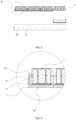
- FIG. 3 is a cross-sectional schematic diagram of a longitudinal cross-sectional structure of a liquid-cooling battery system according to some embodiments of the present disclosure
- FIG. 4 is an enlarged schematic diagram of part A in FIG. 3
- the plurality of through holes 21 are located on one side wall of the box 2.
- One end of the cell 1 passes through the through hole 21 and is immersed in the cooling medium in the liquid-cooling cavity 22, and the other end of the cell is located outside the liquid-cooling cavity 22.
- the box 2 is configured as a box with through holes 21 disposed on the top surface, the bottom end of the cell 1 passes through the through hole 21, so that the lower portion of the cell 1 can be immersed in the cooling medium.
- the busbar is disposed on the top portion of the cell 1, so that the cell 1 with a larger diameter can have a good heat dissipation effect during the normal charging and discharging process.
- FIG. 6 is a schematic cross-sectional diagram of a longitudinal cross-sectional structure of another liquid-cooling battery system according to some embodiments of the present disclosure.
- the box 2 has two side walls disposed oppositely, the plurality of through holes 21 are respectively located on two side walls, and the liquid-cooling cavity 22 is formed between the two side walls.
- the cell 1 passes through two through holes 21 disposed oppositely on two side walls in sequence.
- the cell 1 is provided with a first end, a middle section and a second end disposed in sequence.
- the two side walls of the box 2 are located between the first end and the second end, and the middle section is immersed in the cooling medium in the liquid-cooling cavity 22.
- the box 2 is configured as a box with through holes 21 disposed both on the top surface and the bottom surface, the cell 1 passes through two through holes 21, so that the middle portion of the cell 1 can be immersed in the cooling medium.
- the busbar is disposed on the top portion and the bottom portion of the cell 1, so that the cell 1 with a larger diameter can have a good heat dissipation effect during the normal charging and discharging process.
- FIG. 5 is a schematic diagram of an enlarged structure of part A of another liquid-cooling battery system according to some embodiments of the present disclosure, and the position of part A can be referred to that in FIG. 3 .
- the liquid-cooling battery system further includes an adhesive filling layer 25, and the adhesive filling layer 25 is disposed on the surface of the box 1 where the through holes 21 are disposed, and the adhesive filling layer 25 is configured to form a sealing structure between the cell 1 and the through hole 21, so as to seal the gap between the cell 1 and the through hole 21.
- the adhesive filling layer 25 can be filled on the entire top surface of the box 2, or only filled on part of the top surface of the box 2 close to the through holes 21, as long as the through holes 21 are sealed.
- the adhesive filling layer 25 is provided to ensure the sealing of the through holes 21 and prevent the cooling medium from overflowing from the through holes 21.
- the side surface of the cell 1 is wrapped with an insulating film 11.
- a sealing ring 211 is disposed between the through hole 21 and the cell 1.
- the sealing ring 211 is disposed between the through hole 21 and the cell 1, so that the adhesive is not likely to overflow into the inner portion of the liquid-cooling cavity 22 through the gap between the through hole 21 and the cell 1 due to the sealing effect of the sealing ring 211 during the adhesive filling process.
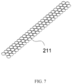
- FIG. 7 is a schematic diagram of a structure of sealing rings according to some embodiments of the present disclosure.
- a plurality of sealing rings 211 are connected in sequence to form an integrated structure, and the top edge of the sealing ring 211 is bent outward, so as to fit the top end surface of the through hole 21.
- the sealing ring 211 is disposed inside the through hole 21, the plurality of sealing rings 211 are disposed into an integrated structure, and the top portion of each of the sealing rings 211 is bent outward, so that the plurality of sealing rings 211 can be installed very easily in the plurality of through holes 21 as a whole and can exactly fit the aperture of each of the inner walls of the through holes 21, and prevent the adhesive from overflowing through the through holes 21 into the liquid-cooling cavity 22 during the adhesive filling process above or below the through holes 21, and thereby optimizing the installation process.
- FIG. 2 is an exploded schematic diagram of a liquid-cooling battery system according to some embodiments of the present disclosure
- FIG. 3 is a cross-sectional schematic diagram of a longitudinal cross-section of a liquid-cooling battery system according to some embodiments of the present disclosure.
- the liquid-cooling battery system includes a plurality of boxes 2, the first side beam 3, and the second side beam 4.
- the first side beam 3 is installed at one end of the plurality of boxes 2, and the second side beam 4 is installed at the other end of plurality of boxes 2.
- An integrated inflow pipe 31 is disposed inside the first side beam 3, and the integrated inflow pipe 31 is connected to a plurality of liquid inlets 23.
- An integrated outflow pipe 41 is disposed inside the second side beam 4, and the integrated outflow pipe 41 is connected to a plurality of outlets 24.
- the plurality of boxes 2 can be expanded along the same plane, or can be stacked along a vertical plane to achieve capacity expansion.
- the first side beam 3 can be provided with multiple rows of ports of the integrated inflow pipe 31
- the second side beam 4 can be provided with multiple rows of ports of the integrated outflow pipe 41, so as to realize the expansion along the vertical plane of the plurality of boxes 2.
- the liquid-cooling battery system is composed of the first side beam 3, the second side beam 4 and a plurality of boxes 2, the integrated inflow pipe 31 is disposed inside the first side beam 3, and the integrated outflow pipe is 41 is disposed inside the second side beam 4, so that the entire battery system can realize a free combination of unlimited number of boxes 2, the first side beam 3 and the second side beam 4 by cutting the lengths of the first side beam 3 and the second side beam 4, thereby facilitating subsequent expansion of the boxes 2.
- a first interface sealing member is connected between the liquid inlet 23 and the integrated inflow pipe 31, and a second interface sealing member is connected between the liquid outlet 24 and the integrated outflow pipe 41.
- first interface sealing member may be a sealing gasket sandwiched between the liquid inlet 23 and the first side beam 3, or may be an adhesive coating layer disposed on the inner side surface of the first side beam 3; it can also be a sealing ring disposed between the liquid inlet 23 and the integrated inflow pipe 31.
- the second interface sealing member can be a sealing gasket sandwiched between the liquid outlet 24 and the second side beam 4, it can be an adhesive coating layer disposed on the inner side surface of the second side beam 4, or it can be a sealing ring disposed between the liquid outlet 24 and the integrated outflow pipe 41.
- the first interface sealing member is disposed between the liquid inlet 23 and the integrated inflow pipe 31, and the second interface sealing member is disposed between the liquid outlet 24 and the integrated outflow pipe 41, so that the connection between the integrated inflow pipe 31 and the liquid inlet 23, and the connection between the integrated outflow pipe 41 and the liquid outlet 24 are not prone to cooling medium leakage.
- the box 2 is configured as a box with two ends open, and the first side beam 3 and the second side beam 4 are added, so that the length of each of the boxes 2, the length of each of the first side beam 3 and the second side beam 4 can be cut freely, and then the plurality of boxes 2 are welded with the first side beam 3 and the second side beam 4 with freely cut lengths, so as to realize that the liquid-cooling module composed of a plurality of boxes 2 can be expanded along the length direction and the width direction of the battery system respectively.
- reinforcing ribs 221 are disposed on the box 2.
- reinforcing ribs 221 are disposed on the housing of the box 2.
- the box 2 includes a bottom wall, a top wall, and side walls, and sometimes, the box includes end walls at two ends of the box 2.
- the bottom wall, top wall, side walls and end walls constitute the housing of the box 2.
- reinforcing ribs 221 are disposed on the housing of the box 2, so that the box 2 is less likely to deform when the cell 1 undergoes thermal expansion and explosion or when the box is collided, thereby improving the service life of the box 2.
- the body of the housing of the box 2 can also be provided with a hollowed structure for heat preservation of the cooling medium.
- each of the end wall and the bottom wall of the box 2 is configured as a hollowed structure.
- filling materials such as foam adhesive can also be filled in the hollowed structure to achieve heat preservation of the liquid-cooling cavity 22.
- a mounting groove is disposed on the inner side of each of the first side beam 3 and the second side beam 4 along the length direction of the first side beam 3 or the second side beam 4 respectively, and the mounting groove fits with the end portion of the box 2.
- the mounting groove can be configured as an elongated groove type or as a trench hole type.
- Mounting grooves are disposed on the inner sides of the first side beam 3 and the second side beam 4 along the length direction, and then the boxes 2 are welded one by one to the mounting grooves on the inner sides of the first side beam 3 and the second side beam 4. Since the height of the box 2 is adapted to the width inside the mounting groove, so the following functions can be achieved. Firstly, the end portions of the box 2 can be positioned when the box 2 is welded, so that all the boxes 2 are on the same level after the boxes 2 are installed.
- connection strength between some of the boxes 2 and the first side beam 3 as well as the second side beam 4 after welding is not enough, under the limiting effects of the mounting groove along the upper and lower direction, and the limiting effects of adjacent box 2 thereto on this box 2 when the adjacent box 2 is connected to the first side beam 3 and the second side beam 4 along the left to right direction, it is ensured that this box 2 is not easily separated from the first side beam 3 and the second side beam 4, thereby alleviating the problem to a certain extent that the welding between the box 2 and the first side beam 3, and the second side beam 4 are easily detached.
- a first welding end plate 32 is disposed on one end surface of the box 2
- a second welding end plate 42 is disposed on the other end surface of the box 2, so as to form the liquid-cooling cavity 22.
- the sealing performance of the welding may be subject to welding leakage due to negligence, which may lead to leakage of the cooling medium.
- the two ends of the box 2 are firstly welded to the first welding end plate 32 and the second welding end plate 42 respectively to form a sealing structure, and after checking the sealing performance of each box 2, the box 2 is welded to the first side beam 3 and the second side beam 4, so as to ensure the sealing performance of the box 2 as much as possible after the box is welded to the first side beam 3 and the second side beam 4.
- this manner allows the length of the box 2 to be flexibly cut according to requirements.
- the box 2 is in welded connection with the first side beam 3 and the second side beam 4.
- the box 2, the first side beam 3 and the second side beam 4 are fixed by welding, thereby ensuring the connection strength between the box body 2 and the first side beam 3, as well as the second side beam 4, and improving the overall service life of the battery system.
Landscapes
- Chemical & Material Sciences (AREA)
- Chemical Kinetics & Catalysis (AREA)
- Electrochemistry (AREA)
- General Chemical & Material Sciences (AREA)
- Engineering & Computer Science (AREA)
- Manufacturing & Machinery (AREA)
- Secondary Cells (AREA)
- Battery Mounting, Suspending (AREA)
Abstract
Description
- This application claims priority to and the benefit of
Chinese Patent Application No. 202322669500.1, filed on September 28, 2023 Chinese Patent Application No. 202311282488.7, filed on September 28, 2023 - The present disclosure relates to the field of battery technology, and in particular, to liquid-cooling battery systems.
- With the explosive growth of the energy storage industry of lithium battery, the operational safety and stability of the battery system has received increasing attention within the industry.
- After the cylindrical cells are grouped, due to the large number of cells and the dense grouping, serious heating occurs during the charging and discharging process, which affects product life and safety. Currently, liquid-cooling temperature control is the mainstream for cylindrical battery systems in the industry. For liquid-cooling temperature control, the cylindrical structure mostly adopts the coiled pipe and liquid-cooling plate process. The cambered surface of the coiled pipe is in contact with the cylindrical surface of the cell through a thermal conductive pad or a thermal conductive adhesive to transfer heat and dissipate heat.
- However, the structure of the coiled pipe results in complex grouping process and low grouping efficiency, and the contact area between the coiled pipe and the cell is small, which can only satisfy the heat dissipation requirements of small cylindrical battery with a smaller diameter. While for larger battery with a larger diameter, this heat dissipation manner cannot effectively dissipate the heat, and the safety and the life of the battery system will still be affected.
- The present disclosure provides a liquid-cooling battery system. The liquid-cooling battery system includes a plurality of cells and one or more boxes, at least one surface of each of the one or more boxes is provided with a plurality of through holes, a liquid-cooling cavity is formed inside each of the one or more boxes, an inner portion of the liquid-cooling cavity is configured to circulate a cooling medium, the liquid-cooling cavity is provided with one or more liquid inlets and one or more liquid outlets, each of the plurality of cells passes through each of the plurality of through hole and is partially immersed in the cooling medium in the liquid-cooling cavity.
- In the liquid-cooling battery system provided by the present disclosure, multiple cells are inserted into the box, and then the box inserted with the multiple cells is sealed. Firstly, by using such a structure, multiple cells can be respectively and directly immersed in the cooling medium in the box, thereby maximizing the heat dissipation area of the cell during charging and discharging process. The heat generated by the cell during the charging and discharging process is directly transferred to the cooling medium without passing through a thermal conductive adhesive, the part of the cell inserted into the box is immersed in the cooling medium, and the contact area between the cell and the cooling medium in which the cell is immersed is maximized, so that the heat dissipation efficiency is higher. Secondly, in the present disclosure, the cell is directly immersed into the cooling medium in the liquid-cooling box to achieve the integration of the liquid-cooling box. There is no need to dispose liquid-cooling plates, water pipes and joints next to the cell, which is easier to implement and is conducive to addressing cost problems. Thirdly, the cell is directly disposed inside the liquid-cooling cavity, the installation processes such as adhesive coating, curing, stacking, and hoisting are eliminated, thereby resulting in higher production efficiency.
-
-
FIG. 1 is a schematic diagram of a structure of a liquid-cooling battery system according to some embodiments of the present disclosure; -
FIG. 2 is a schematic diagram of an exploded structure of a liquid-cooling battery system according to some embodiments of the present disclosure; -
FIG. 3 is a cross-sectional schematic diagram of a longitudinal cross-sectional structure of a liquid-cooling battery system according to some embodiments of the present disclosure; -
FIG. 4 is a schematic diagram of an enlarged structure of part A inFIG. 3 ; -
FIG. 5 is a schematic diagram of an enlarged structure of part A of another liquid-cooling battery system according to some embodiments of the present disclosure; -
FIG. 6 is a cross-sectional schematic diagram of a longitudinal cross-sectional structure of another liquid-cooling battery system according to some embodiments of the present disclosure; -
FIG. 7 is a schematic diagram of a structure of sealing rings according to some embodiments of the present disclosure. - 1. Cell; 11. Insulating film; 2. Box; 21. Through hole; 211. Sealing ring; 22. Liquid-cooling cavity; 221. Reinforcing rib; 23. Liquid inlet; 24. Liquid outlet; 25. Adhesive filling layer; 3. First side beam; 31. Integrated inflow pipe; 32. First welding end plate; 4. Second side beam; 41. Integrated outflow pipe; 42. Second welding end plate.
- In the description of the present disclosure, it should be understood that the words "first" and "second" are only used for descriptive purposes and cannot be understood as indicating or implying relative importance or indicating the number of indicated technical features. Therefore, the features defined as the "first" and the "second" may explicitly or implicitly include one or more features. In the description of the present disclosure, "a plurality of" means two or more than two, unless otherwise explicitly and specifically limited.
- In the present disclosure, the word "exemplary" refers to "serving as an example, illustration, or explanation". Any embodiment described herein as "exemplary" is not necessarily to be construed as preferred or more advantageous over other embodiments. The following description is presented to enable any person skilled in the art to achieve and use the present disclosure. In the following description, details are set forth for the purpose of explanation. It will be understood that one of ordinary skill in the art will recognize that the present disclosure can be achieved without these specific details. In other examples, well-known structures and processes have not been described in detail herein to avoid obscuring the description of the present disclosure due to unnecessary details. Therefore, the present disclosure is not intended to be limited to the embodiments described but is consistent with the widest scope in accord with the principles disclosed in the present disclosure.
- The battery system is generally accompanied by a heat release process during the charging and discharging process. During the heat release process, it is generally required to cool down the battery system, so that the battery system can work in a more suitable operating temperature environment.
- In the battery system,
cells 1 are generally combined into battery modules, and air-cooling heat dissipation or liquid-cooling heat dissipation are performed inside the battery module. Liquid-cooling heat dissipation involves transferring heat and exchanging heat by the complex coiled pipes (with coolant filled in the coiled pipes) and the thermal conductive adhesive disposed between adjacent battery modules. The efficiency of air-cooling heat dissipation is lower than the efficiency of liquid-cooling heat dissipation. However, by disposing complex coiled pipes and thermal conductive adhesive between adjacent battery modules to dissipate heat, it relies heavily on the heat transfer capability of the thermal conductive adhesive itself, and since the contact area between the coiled pipe and the battery module is small, the heat dissipation area is small, thereby resulting in low heat dissipation efficiency. Although the air-cooling heat dissipation or liquid-cooling heat dissipation described above can satisfy the heat dissipation requirements of small batteries, the heat dissipation efficiency is seriously insufficient for large batteries, and the installation process is complicated and the material cost is high. - Based on the above, embodiments of the present disclosure provide a liquid-cooling battery system. Referring to
FIG. 1 and FIG. 2, FIG. 1 is a schematic diagram of a structure of a liquid-cooling battery system according to some embodiments of the present disclosure, andFIG. 2 is an exploded schematic diagram of a liquid-cooling battery system according to some embodiments of the present disclosure. The liquid-cooling battery system includes a plurality ofcells 1 and one ormore boxes 2, a surface of thebox 2 is provided with a plurality of throughholes 21, a liquid-coolingcavity 22 is formed inside thebox 2, an inner portion of the liquid-coolingcavity 22 is configured to circulate a cooling medium, the liquid-coolingcavity 22 is provided with one or moreliquid inlets 23 and one or moreliquid outlets 24, each of thecells 1 passes through each of the throughholes 21 and is partially immersed in the cooling medium in the liquid-coolingcavity 22. - It should be understood that the position where the through
hole 21 and thecell 1 are in contact needs to be sealed to form a sealed liquid-coolingcavity 22, the position can be sealed by adhesive coating or adhesive filling, so as to prevent the cooling medium from flowing out from the inside of the liquid-coolingcavity 22, and thereby affecting other components on thebox 2 of the battery system, such as affecting the normal operation of the busbar and the battery temperature detecting system. - It should be understood that the shape of the
box 2 can be a cube, a cuboid, a cylinder with a hexagonal top surface, an ellipsoid, or an irregular box. - The cooling medium can be a coolant inside a general coiled pipe, for example, it can be water, ionized water, or oil.
- It should be noted that in the related technology, during the preparation process, the coiled pipe configured to be in direct contact with the
cell 1 for achieving heat transfer needs to be coated with adhesive firstly, then the coiled pipe coated with adhesive is bonded to thecell 1, then the adhesive coated on the coiled pipe is cured, then the battery modules are stacked to a battery group after the coated adhesive is cured, and finally the stacked battery group is hoisted into a protective box to form a battery pack. - Device for circulating cooling medium and heat dissipating device may be connected between the
liquid inlet 23 and theliquid outlet 24 outside the liquid-coolingcavity 22, such as a pressure pump to increase fluid pressure and an evaporator configured to dissipate heat to the outside rapidly. In this way, when the liquid-coolingcavity 22 receives a large amount of heat generated from the charging and discharging process of thecell 1, the heat can firstly be quickly diluted by a large amount of cooling medium, then taken out by theliquid outlet 24 to the evaporator for external heat dissipation, and then the cooling medium after being fully heat-dissipated is sent back to the inner portion of the liquid-coolingcavity 22 through theliquid inlet 23 by the pressure pump for preliminary heat dissipation, thereby achieving a good circulation and heat dissipation effect. - In the embodiments of the present disclosure,
multiple cells 1 independently disposed are inserted into thebox 2, and then thebox 2 in which themultiple cells 1 are inserted is sealed. Firstly, by using such a structure,multiple cells 1 can be respectively and directly immersed in the cooling medium, thereby maximizing the heat dissipating area of thecell 1 during charging and discharging process. The heat generated by thecell 1 during the charging and discharging process is directly transferred to the cooling medium without passing through the thermal conductive adhesive, the periphery of thecell 1 is completely immersed in the cooling medium, and the contact area between thecell 1 and the cooling medium in which the cell is immersed is maximized, so that the heat dissipation efficiency is higher. Secondly, in the present disclosure, thecell 1 is directly immersed into the cooling medium in the liquid-cooling box. There is no need to dispose liquid-cooling plates, water pipes and joints next to the cell, which is easier to implement and is conducive to addressing cost problems. Thirdly, thecell 1 is directly disposed inside the liquid-coolingcavity 22, the installation processes such as adhesive coating, curing, stacking, and hoisting are eliminated, thereby resulting in higher production efficiency. - Referring to
FIG. 3 to FIG. 4, FIG. 3 is a cross-sectional schematic diagram of a longitudinal cross-sectional structure of a liquid-cooling battery system according to some embodiments of the present disclosure, andFIG. 4 is an enlarged schematic diagram of part A inFIG. 3 . In some embodiments of the present disclosure, the plurality of throughholes 21 are located on one side wall of thebox 2. One end of thecell 1 passes through the throughhole 21 and is immersed in the cooling medium in the liquid-coolingcavity 22, and the other end of the cell is located outside the liquid-coolingcavity 22. - In some embodiments of the present disclosure, the
box 2 is configured as a box with throughholes 21 disposed on the top surface, the bottom end of thecell 1 passes through the throughhole 21, so that the lower portion of thecell 1 can be immersed in the cooling medium. The busbar is disposed on the top portion of thecell 1, so that thecell 1 with a larger diameter can have a good heat dissipation effect during the normal charging and discharging process. - Referring to
FIG. 6, FIG. 6 is a schematic cross-sectional diagram of a longitudinal cross-sectional structure of another liquid-cooling battery system according to some embodiments of the present disclosure. In some embodiments of the present disclosure, thebox 2 has two side walls disposed oppositely, the plurality of throughholes 21 are respectively located on two side walls, and the liquid-coolingcavity 22 is formed between the two side walls. Thecell 1 passes through two throughholes 21 disposed oppositely on two side walls in sequence. Thecell 1 is provided with a first end, a middle section and a second end disposed in sequence. The two side walls of thebox 2 are located between the first end and the second end, and the middle section is immersed in the cooling medium in the liquid-coolingcavity 22. - In some embodiments of the present disclosure, the
box 2 is configured as a box with throughholes 21 disposed both on the top surface and the bottom surface, thecell 1 passes through two throughholes 21, so that the middle portion of thecell 1 can be immersed in the cooling medium. The busbar is disposed on the top portion and the bottom portion of thecell 1, so that thecell 1 with a larger diameter can have a good heat dissipation effect during the normal charging and discharging process. - In some embodiments of the present disclosure, referring to
FIG. 5, FIG. 5 is a schematic diagram of an enlarged structure of part A of another liquid-cooling battery system according to some embodiments of the present disclosure, and the position of part A can be referred to that inFIG. 3 . The liquid-cooling battery system further includes anadhesive filling layer 25, and theadhesive filling layer 25 is disposed on the surface of thebox 1 where the throughholes 21 are disposed, and theadhesive filling layer 25 is configured to form a sealing structure between thecell 1 and the throughhole 21, so as to seal the gap between thecell 1 and the throughhole 21. - It should be understood that the
adhesive filling layer 25 can be filled on the entire top surface of thebox 2, or only filled on part of the top surface of thebox 2 close to the throughholes 21, as long as the throughholes 21 are sealed. - In some embodiments of the present disclosure, the
adhesive filling layer 25 is provided to ensure the sealing of the throughholes 21 and prevent the cooling medium from overflowing from the through holes 21. - Referring to
FIG. 4 andFIG. 5 , in some embodiments of the present disclosure, the side surface of thecell 1 is wrapped with an insulatingfilm 11. - In some embodiment of the present disclosure, by wrapping the insulating
film 11 on the side surface of thecell 1, current leakage is less likely to occur between the surface of thecell 1 and the cooling medium, thereby enabling the entire battery system to operate more safely and stably. - Referring to
FIG. 5 , in some embodiments of the present disclosure, a sealingring 211 is disposed between the throughhole 21 and thecell 1. - In some embodiments of the present disclosure, the sealing
ring 211 is disposed between the throughhole 21 and thecell 1, so that the adhesive is not likely to overflow into the inner portion of the liquid-coolingcavity 22 through the gap between the throughhole 21 and thecell 1 due to the sealing effect of the sealingring 211 during the adhesive filling process. - Referring to
FIG. 5 andFIG. 7, FIG. 7 is a schematic diagram of a structure of sealing rings according to some embodiments of the present disclosure. A plurality of sealingrings 211 are connected in sequence to form an integrated structure, and the top edge of the sealingring 211 is bent outward, so as to fit the top end surface of the throughhole 21. - In some embodiments of the present disclosure, the sealing
ring 211 is disposed inside the throughhole 21, the plurality of sealingrings 211 are disposed into an integrated structure, and the top portion of each of the sealing rings 211 is bent outward, so that the plurality of sealingrings 211 can be installed very easily in the plurality of throughholes 21 as a whole and can exactly fit the aperture of each of the inner walls of the throughholes 21, and prevent the adhesive from overflowing through the throughholes 21 into the liquid-coolingcavity 22 during the adhesive filling process above or below the throughholes 21, and thereby optimizing the installation process. - Referring to
FIG. 2 andFIG. 3 ,FIG. 2 is an exploded schematic diagram of a liquid-cooling battery system according to some embodiments of the present disclosure, andFIG. 3 is a cross-sectional schematic diagram of a longitudinal cross-section of a liquid-cooling battery system according to some embodiments of the present disclosure. In some embodiments of the present disclosure, the liquid-cooling battery system includes a plurality ofboxes 2, thefirst side beam 3, and the second side beam 4. The first side beam 3is installed at one end of the plurality ofboxes 2, and the second side beam 4 is installed at the other end of plurality ofboxes 2. Anintegrated inflow pipe 31 is disposed inside thefirst side beam 3, and theintegrated inflow pipe 31 is connected to a plurality ofliquid inlets 23. Anintegrated outflow pipe 41 is disposed inside the second side beam 4, and theintegrated outflow pipe 41 is connected to a plurality ofoutlets 24. - It should be understood that the plurality of
boxes 2 can be expanded along the same plane, or can be stacked along a vertical plane to achieve capacity expansion. Correspondingly, thefirst side beam 3 can be provided with multiple rows of ports of theintegrated inflow pipe 31, and the second side beam 4 can be provided with multiple rows of ports of the integratedoutflow pipe 41, so as to realize the expansion along the vertical plane of the plurality ofboxes 2. - In some embodiments of the present disclosure, the liquid-cooling battery system is composed of the
first side beam 3, the second side beam 4 and a plurality ofboxes 2, theintegrated inflow pipe 31 is disposed inside thefirst side beam 3, and the integrated outflow pipe is 41 is disposed inside the second side beam 4, so that the entire battery system can realize a free combination of unlimited number ofboxes 2, thefirst side beam 3 and the second side beam 4 by cutting the lengths of thefirst side beam 3 and the second side beam 4, thereby facilitating subsequent expansion of theboxes 2. - In some embodiments of the present disclosure, a first interface sealing member is connected between the
liquid inlet 23 and theintegrated inflow pipe 31, and a second interface sealing member is connected between theliquid outlet 24 and theintegrated outflow pipe 41. - It should be noted that the first interface sealing member may be a sealing gasket sandwiched between the
liquid inlet 23 and thefirst side beam 3, or may be an adhesive coating layer disposed on the inner side surface of thefirst side beam 3; it can also be a sealing ring disposed between theliquid inlet 23 and theintegrated inflow pipe 31. The second interface sealing member can be a sealing gasket sandwiched between theliquid outlet 24 and the second side beam 4, it can be an adhesive coating layer disposed on the inner side surface of the second side beam 4, or it can be a sealing ring disposed between theliquid outlet 24 and theintegrated outflow pipe 41. - In some embodiments of the present disclosure, the first interface sealing member is disposed between the
liquid inlet 23 and theintegrated inflow pipe 31, and the second interface sealing member is disposed between theliquid outlet 24 and theintegrated outflow pipe 41, so that the connection between theintegrated inflow pipe 31 and theliquid inlet 23, and the connection between theintegrated outflow pipe 41 and theliquid outlet 24 are not prone to cooling medium leakage. - Referring to
FIG. 2 , in some embodiments of the present disclosure, two end surfaces of thebox 2 are open, and two end surfaces of thebox 2 are respectively connected to thefirst side beam 3 and the second side beam 4 to form the liquid-coolingcavity 22. - In some embodiments of the present disclosure, the
box 2 is configured as a box with two ends open, and thefirst side beam 3 and the second side beam 4 are added, so that the length of each of theboxes 2, the length of each of thefirst side beam 3 and the second side beam 4 can be cut freely, and then the plurality ofboxes 2 are welded with thefirst side beam 3 and the second side beam 4 with freely cut lengths, so as to realize that the liquid-cooling module composed of a plurality ofboxes 2 can be expanded along the length direction and the width direction of the battery system respectively. - Referring to
FIG. 5 , in some embodiments of the present disclosure, reinforcingribs 221 are disposed on thebox 2. Specifically, reinforcingribs 221 are disposed on the housing of thebox 2. Generally, thebox 2 includes a bottom wall, a top wall, and side walls, and sometimes, the box includes end walls at two ends of thebox 2. The bottom wall, top wall, side walls and end walls constitute the housing of thebox 2. - In some embodiments of the present disclosure, reinforcing
ribs 221 are disposed on the housing of thebox 2, so that thebox 2 is less likely to deform when thecell 1 undergoes thermal expansion and explosion or when the box is collided, thereby improving the service life of thebox 2. In addition, the body of the housing of thebox 2 can also be provided with a hollowed structure for heat preservation of the cooling medium. As an example, referring toFIG. 5 , each of the end wall and the bottom wall of thebox 2 is configured as a hollowed structure. Exemplarily, filling materials such as foam adhesive can also be filled in the hollowed structure to achieve heat preservation of the liquid-coolingcavity 22. - Referring to
FIG. 3 , in some embodiments of the present disclosure, a mounting groove is disposed on the inner side of each of thefirst side beam 3 and the second side beam 4 along the length direction of thefirst side beam 3 or the second side beam 4 respectively, and the mounting groove fits with the end portion of thebox 2. - It should be understood that the mounting groove can be configured as an elongated groove type or as a trench hole type.
- Mounting grooves are disposed on the inner sides of the
first side beam 3 and the second side beam 4 along the length direction, and then theboxes 2 are welded one by one to the mounting grooves on the inner sides of thefirst side beam 3 and the second side beam 4. Since the height of thebox 2 is adapted to the width inside the mounting groove, so the following functions can be achieved. Firstly, the end portions of thebox 2 can be positioned when thebox 2 is welded, so that all theboxes 2 are on the same level after theboxes 2 are installed. Secondly, because the connection strength between some of theboxes 2 and thefirst side beam 3 as well as the second side beam 4 after welding is not enough, under the limiting effects of the mounting groove along the upper and lower direction, and the limiting effects ofadjacent box 2 thereto on thisbox 2 when theadjacent box 2 is connected to thefirst side beam 3 and the second side beam 4 along the left to right direction, it is ensured that thisbox 2 is not easily separated from thefirst side beam 3 and the second side beam 4, thereby alleviating the problem to a certain extent that the welding between thebox 2 and thefirst side beam 3, and the second side beam 4 are easily detached. - Referring to
FIG. 2 , in some embodiments of the present disclosure, a firstwelding end plate 32 is disposed on one end surface of thebox 2, and a secondwelding end plate 42 is disposed on the other end surface of thebox 2, so as to form the liquid-coolingcavity 22. - When the
first side beam 3 is directly welded to the end portion of thebox body 2, the sealing performance of the welding may be subject to welding leakage due to negligence, which may lead to leakage of the cooling medium. - Therefore, after the two ends of the
box 2 are cut, the two ends of thebox 2 are firstly welded to the firstwelding end plate 32 and the secondwelding end plate 42 respectively to form a sealing structure, and after checking the sealing performance of eachbox 2, thebox 2 is welded to thefirst side beam 3 and the second side beam 4, so as to ensure the sealing performance of thebox 2 as much as possible after the box is welded to thefirst side beam 3 and the second side beam 4. Compared with the manner that thebox 2 is directly configured as a sealed structure, this manner allows the length of thebox 2 to be flexibly cut according to requirements. - In some embodiments of the present disclosure, the
box 2 is in welded connection with thefirst side beam 3 and the second side beam 4. - In some embodiments of the present disclosure, the
box 2, thefirst side beam 3 and the second side beam 4 are fixed by welding, thereby ensuring the connection strength between thebox body 2 and thefirst side beam 3, as well as the second side beam 4, and improving the overall service life of the battery system. - In the above embodiments, each embodiment is described with its own emphasis. For parts that are not described in detail in a certain embodiment, reference can be made to the relevant descriptions of other embodiments described above, which are not described again herein.
Claims (15)
- A liquid-cooling battery system comprising a plurality of cells (1) and one or more boxes (2), wherein at least one surface of each of the one or more boxes (2) is provided with a plurality of through holes (21), a liquid-cooling cavity (22) is formed inside each of the one or more boxes (2), an inner portion of the liquid-cooling cavity (22) is configured to circulate a cooling medium, the liquid-cooling cavity (22) is provided with one or more liquid inlets (23) and one or more liquid outlets (24), each of the plurality of cells (1) passes through each of the plurality of through holes (21) and is partially immersed in the cooling medium in the liquid-cooling cavity (22).
- The liquid-cooling battery system according to claim 1, wherein the plurality of through holes (21) are located on one side wall of each of the one or more boxes (2), one end of each of the plurality of cells (1) passes through each of the plurality of through holes (21) and is immersed in the cooling medium in the liquid-cooling cavity (22), and another end of each of the plurality of cells is located outside the liquid-cooling cavity (22).
- The liquid-cooling battery system according to claim 1, wherein each of the one or more boxes (2) is provided with two side walls disposed oppositely, the plurality of through holes (21) are respectively located on the two side walls, and the liquid-cooling cavity (22) is formed between the two side walls; and each of the plurality of cells (1) passes through two of the plurality of through holes (21) located on the two side walls in sequence, the each of the plurality of cells (1) is provided with a first end, a middle section and a second end disposed in sequence, the two side walls of each of the one or more boxes (2) are located between the first end and the second end, and the middle section is immersed in the cooling medium in the liquid-cooling cavity (22).
- The liquid-cooling battery system according to claim 1, wherein the liquid-cooling battery system further comprises an adhesive filling layer (25), the adhesive filled layer (25) is disposed on the at least one surface of each of the one or more boxes (2) where the plurality of through holes (21) are disposed, and the adhesive filling layer (25) is configured to form a sealing structure between the plurality of cells (1) and the plurality of through holes (21).
- The liquid-cooling battery system according to claim 1, wherein a side surface of each of the plurality of cells (1) is wrapped with an insulating film (11).
- The liquid-cooling battery system according to claim 1, wherein each of a plurality of sealing rings (211) is disposed between each of the plurality of through holes (21) and each of the plurality of cells (1).
- The liquid-cooling battery system according to claim 6, wherein the plurality of sealing rings (211) are connected in sequence to form an integrated structure, and a top edge of each of the plurality of sealing rings (211) is bent outward to fit a top end surface of each of the plurality of through holes (21).
- The liquid-cooling battery system according to any one of claims 1 to 7, wherein the liquid-cooling battery system comprises multiple said boxes (2), a first side beam (3) and a second side beam (4), the first side beam (3) is installed at one end of the multiple said boxes (2), the second side beam (4) is installed at another end of the multiple said boxes (2), an integrated inflow pipe (31) is disposed inside the first side beam (3), the integrated inflow pipe (31) is connected to multiple said liquid inlets (23), an integrated outflow pipe (41) is disposed inside the second side beam (4), and the integrated outflow pipe (41) is connected to multiple said liquid outlets (24).
- The liquid-cooling battery system according to claim 8, wherein a first interface sealing member is disposed between each of the multiple said liquid inlets (23) and the integrated inflow pipe (31), and a second interface sealing member is disposed between each of the multiple said liquid outlets (24) and the integrated outflow pipe (41).
- The liquid-cooling battery system according to claim 8, wherein two end surfaces of each of the multiple said boxes (2) are open, the two end surfaces of each of the multiple said boxes (2) are connected to the first side beam (3) and the second side beam (4) respectively to form the liquid-cooling cavity (22).
- The liquid-cooling battery system according to claim 8, wherein one end surface of each of the multiple said boxes (2) is provided with a first welding end plate (32), and another end surface of each of the multiple said boxes (2) is provided with a second welding end plate (42) to form the liquid-cooling cavity (22).
- The liquid-cooling battery system according to claim 8, wherein an inner side of the first side beam (3) and an inner side of the second side beam (4) are respectively provided with mounting grooves along a length direction, each of the mounting grooves is adapted to end portions of each of the multiple said boxes (2), and the end portions of each of the multiple said boxes (2) are welded in the mounting grooves.
- The liquid-cooling battery system according to any one of claims 1 to 7, wherein reinforcing ribs (221) are disposed on a housing of one of the one or more boxes (2).
- The liquid-cooled battery system according to any one of claims 1 to 7, wherein a body of a housing of one of the one or more boxes (2) is a hollowed structure.
- The liquid-cooling battery system according to claim 14, wherein the hollowed structure is filled with foam adhesive.
Applications Claiming Priority (3)
| Application Number | Priority Date | Filing Date | Title |
|---|---|---|---|
| CN202311282488.7A CN117117385A (en) | 2023-09-28 | 2023-09-28 | A submersible liquid-cooled battery system |
| CN202322669500.1U CN221352892U (en) | 2023-09-28 | 2023-09-28 | Immersed liquid cooling battery system |
| PCT/CN2024/104263 WO2025066407A1 (en) | 2023-09-28 | 2024-07-08 | Liquid-cooled battery system |
Publications (2)
| Publication Number | Publication Date |
|---|---|
| EP4557459A1 true EP4557459A1 (en) | 2025-05-21 |
| EP4557459A4 EP4557459A4 (en) | 2026-01-21 |
Family
ID=93853133
Family Applications (1)
| Application Number | Title | Priority Date | Filing Date |
|---|---|---|---|
| EP24809537.4A Pending EP4557459A4 (en) | 2023-09-28 | 2024-07-08 | LIQUID-COOLED BATTERY SYSTEM |
Country Status (3)
| Country | Link |
|---|---|
| US (1) | US20250158166A1 (en) |
| EP (1) | EP4557459A4 (en) |
| WO (1) | WO2025066407A1 (en) |
Families Citing this family (1)
| Publication number | Priority date | Publication date | Assignee | Title |
|---|---|---|---|---|
| USD1125032S1 (en) * | 2024-01-09 | 2026-05-05 | Sungrow Power Supply Co., Ltd. | Lithium battery pack |
Family Cites Families (13)
| Publication number | Priority date | Publication date | Assignee | Title |
|---|---|---|---|---|
| DE102014106852A1 (en) * | 2014-05-15 | 2015-11-19 | Dr. Ing. H.C. F. Porsche Aktiengesellschaft | battery module |
| CN106972191A (en) * | 2016-12-01 | 2017-07-21 | 动能创科股份有限公司 | Lithium ion battery bag or battery modules, coolant and cooling means suitable for the lithium ion battery bag or battery modules |
| AT520409B1 (en) * | 2017-09-05 | 2020-02-15 | Miba Ag | accumulator |
| US20230170551A1 (en) * | 2020-04-24 | 2023-06-01 | Tvs Motor Company Limited | Battery module with a cell holder assembly |
| CN111446397A (en) * | 2020-04-26 | 2020-07-24 | 天津市捷威动力工业有限公司 | Battery pack box and battery pack |
| HRP20201569B1 (en) * | 2020-10-02 | 2023-06-23 | Rimac Automobili D.O.O. | Battery module and method for cooling the battery module |
| FR3129530B1 (en) * | 2021-11-23 | 2024-02-02 | Commissariat Energie Atomique | Enclosure for a battery module or battery pack, with a waterproof membrane intended to allow circulation of a heat transfer fluid within it for optimal cooling of the accumulators of the module or pack, leaving the output terminals clear. |
| CN216529125U (en) * | 2021-11-30 | 2022-05-13 | 比亚迪股份有限公司 | Box, battery package and electric vehicle |
| CN218351552U (en) * | 2022-10-09 | 2023-01-20 | 江苏正力新能电池技术有限公司 | Battery module |
| CN218896692U (en) * | 2022-12-12 | 2023-04-21 | 蜂巢能源科技股份有限公司 | Battery pack and power device with same |
| CN115863897A (en) * | 2022-12-26 | 2023-03-28 | 湖北亿纬动力有限公司 | Battery core and battery assembly |
| CN115911662B (en) * | 2023-01-03 | 2025-06-03 | 楚能新能源股份有限公司 | Immersed liquid-cooled battery module structure and assembly method thereof |
| CN117117385A (en) * | 2023-09-28 | 2023-11-24 | 惠州亿纬锂能股份有限公司 | A submersible liquid-cooled battery system |
-
2024
- 2024-07-08 WO PCT/CN2024/104263 patent/WO2025066407A1/en active Pending
- 2024-07-08 EP EP24809537.4A patent/EP4557459A4/en active Pending
-
2025
- 2025-01-17 US US19/026,870 patent/US20250158166A1/en active Pending
Also Published As
| Publication number | Publication date |
|---|---|
| EP4557459A4 (en) | 2026-01-21 |
| WO2025066407A1 (en) | 2025-04-03 |
| US20250158166A1 (en) | 2025-05-15 |
Similar Documents
| Publication | Publication Date | Title |
|---|---|---|
| CN116130834A (en) | Immersed liquid cooling energy storage battery pack structure | |
| KR102208720B1 (en) | Battery Heat Sink for Cooling by Phase Change Materials and Method thereof | |
| CN110707393A (en) | Safe and energy-saving lithium battery pack dual-mode thermal management system and method | |
| CN115458832A (en) | Power battery cooling system with synergistic effect of multi-element composite phase change material and water cooling | |
| CN111933846A (en) | Battery pack box body of integrated liquid cooling system and electric vehicle | |
| WO2018030821A1 (en) | Battery pack having improved cooling structure | |
| KR102863723B1 (en) | Can type battery module comprising immersion cooling part | |
| CN116387674A (en) | A cooling battery box and battery pack | |
| CN110165332A (en) | A kind of radiating device of battery pack for concentrating heat dissipation | |
| CN114639866A (en) | Lithium ion battery thermal management device based on composite phase change material and liquid cooling | |
| US20250158166A1 (en) | Liquid-cooling battery systems | |
| CN111864302A (en) | A power battery pack heat dissipation management system | |
| CN115528349A (en) | Single battery and battery module of integrated thermal management structure | |
| WO2024083083A1 (en) | Battery and electric device | |
| CN115692900A (en) | High-capacity battery | |
| CN114284594A (en) | A battery and battery pack | |
| JP7395232B2 (en) | Battery packs and devices containing them | |
| KR20240064712A (en) | Battery and its manufacturing method and electrical device | |
| CN209804852U (en) | A heat dissipation device for a battery pack with centralized heat dissipation | |
| CN115224393A (en) | A liquid cooling device and battery module | |
| CN222422057U (en) | Liquid-cooled energy storage battery pack | |
| CN117117385A (en) | A submersible liquid-cooled battery system | |
| CN221304801U (en) | Battery pack and power device | |
| WO2026036488A1 (en) | Battery pack | |
| CN117748001A (en) | Battery box, battery pack and electric equipment |
Legal Events
| Date | Code | Title | Description |
|---|---|---|---|
| STAA | Information on the status of an ep patent application or granted ep patent |
Free format text: STATUS: UNKNOWN |
|
| STAA | Information on the status of an ep patent application or granted ep patent |
Free format text: STATUS: THE INTERNATIONAL PUBLICATION HAS BEEN MADE |
|
| PUAI | Public reference made under article 153(3) epc to a published international application that has entered the european phase |
Free format text: ORIGINAL CODE: 0009012 |
|
| STAA | Information on the status of an ep patent application or granted ep patent |
Free format text: STATUS: REQUEST FOR EXAMINATION WAS MADE |
|
| 17P | Request for examination filed |
Effective date: 20241129 |
|
| AK | Designated contracting states |
Kind code of ref document: A1 Designated state(s): AL AT BE BG CH CY CZ DE DK EE ES FI FR GB GR HR HU IE IS IT LI LT LU LV MC ME MK MT NL NO PL PT RO RS SE SI SK SM TR |
|
| A4 | Supplementary search report drawn up and despatched |
Effective date: 20251219 |
|
| RIC1 | Information provided on ipc code assigned before grant |
Ipc: H01M 10/613 20140101AFI20251215BHEP Ipc: H01M 10/643 20140101ALI20251215BHEP Ipc: H01M 10/6567 20140101ALI20251215BHEP |