EP4557319A1 - Resistor structure and a voltage divider arrangement - Google Patents
Resistor structure and a voltage divider arrangement Download PDFInfo
- Publication number
- EP4557319A1 EP4557319A1 EP23210185.7A EP23210185A EP4557319A1 EP 4557319 A1 EP4557319 A1 EP 4557319A1 EP 23210185 A EP23210185 A EP 23210185A EP 4557319 A1 EP4557319 A1 EP 4557319A1
- Authority
- EP
- European Patent Office
- Prior art keywords
- resistive
- insulator element
- thickness
- resistor structure
- insulator
- Prior art date
- Legal status (The legal status is an assumption and is not a legal conclusion. Google has not performed a legal analysis and makes no representation as to the accuracy of the status listed.)
- Pending
Links
Images




Classifications
-
- H—ELECTRICITY
- H01—ELECTRIC ELEMENTS
- H01C—RESISTORS
- H01C7/00—Non-adjustable resistors formed as one or more layers or coatings; Non-adjustable resistors made from powdered conducting material or powdered semi-conducting material with or without insulating material
- H01C7/22—Elongated resistive element being bent or curved, e.g. sinusoidal, helical
-
- H—ELECTRICITY
- H01—ELECTRIC ELEMENTS
- H01C—RESISTORS
- H01C1/00—Details
- H01C1/02—Housing; Enclosing; Embedding; Filling the housing or enclosure
- H01C1/028—Housing; Enclosing; Embedding; Filling the housing or enclosure the resistive element being embedded in insulation with outer enclosing sheath
-
- H—ELECTRICITY
- H01—ELECTRIC ELEMENTS
- H01C—RESISTORS
- H01C1/00—Details
- H01C1/14—Terminals or tapping points specially adapted for resistors; Arrangements of terminals or tapping points on resistors
-
- H—ELECTRICITY
- H01—ELECTRIC ELEMENTS
- H01C—RESISTORS
- H01C1/00—Details
- H01C1/01—Mounting; Supporting
-
- H—ELECTRICITY
- H01—ELECTRIC ELEMENTS
- H01C—RESISTORS
- H01C1/00—Details
- H01C1/02—Housing; Enclosing; Embedding; Filling the housing or enclosure
-
- H—ELECTRICITY
- H01—ELECTRIC ELEMENTS
- H01C—RESISTORS
- H01C13/00—Resistors not provided for elsewhere
- H01C13/02—Structural combinations of resistors
-
- H—ELECTRICITY
- H01—ELECTRIC ELEMENTS
- H01C—RESISTORS
- H01C3/00—Non-adjustable metal resistors made of wire or ribbon, e.g. coiled, woven or formed as grids
- H01C3/10—Non-adjustable metal resistors made of wire or ribbon, e.g. coiled, woven or formed as grids the resistive element having zig-zag or sinusoidal configuration
-
- H—ELECTRICITY
- H01—ELECTRIC ELEMENTS
- H01C—RESISTORS
- H01C3/00—Non-adjustable metal resistors made of wire or ribbon, e.g. coiled, woven or formed as grids
- H01C3/14—Non-adjustable metal resistors made of wire or ribbon, e.g. coiled, woven or formed as grids the resistive element being formed in two or more coils or loops continuously wound as a spiral, helical or toroidal winding
- H01C3/18—Non-adjustable metal resistors made of wire or ribbon, e.g. coiled, woven or formed as grids the resistive element being formed in two or more coils or loops continuously wound as a spiral, helical or toroidal winding wound on a flat or ribbon base
-
- H—ELECTRICITY
- H01—ELECTRIC ELEMENTS
- H01C—RESISTORS
- H01C3/00—Non-adjustable metal resistors made of wire or ribbon, e.g. coiled, woven or formed as grids
- H01C3/14—Non-adjustable metal resistors made of wire or ribbon, e.g. coiled, woven or formed as grids the resistive element being formed in two or more coils or loops continuously wound as a spiral, helical or toroidal winding
- H01C3/20—Non-adjustable metal resistors made of wire or ribbon, e.g. coiled, woven or formed as grids the resistive element being formed in two or more coils or loops continuously wound as a spiral, helical or toroidal winding wound on cylindrical or prismatic base
-
- G—PHYSICS
- G01—MEASURING; TESTING
- G01R—MEASURING ELECTRIC VARIABLES; MEASURING MAGNETIC VARIABLES
- G01R15/00—Details of measuring arrangements of the types provided for in groups G01R17/00 - G01R29/00, G01R33/00 - G01R33/26 or G01R35/00
- G01R15/04—Voltage dividers
-
- H—ELECTRICITY
- H01—ELECTRIC ELEMENTS
- H01C—RESISTORS
- H01C1/00—Details
- H01C1/14—Terminals or tapping points specially adapted for resistors; Arrangements of terminals or tapping points on resistors
- H01C1/148—Terminals or tapping points specially adapted for resistors; Arrangements of terminals or tapping points on resistors the terminals embracing or surrounding the resistive element
-
- H—ELECTRICITY
- H01—ELECTRIC ELEMENTS
- H01C—RESISTORS
- H01C3/00—Non-adjustable metal resistors made of wire or ribbon, e.g. coiled, woven or formed as grids
- H01C3/10—Non-adjustable metal resistors made of wire or ribbon, e.g. coiled, woven or formed as grids the resistive element having zig-zag or sinusoidal configuration
- H01C3/12—Non-adjustable metal resistors made of wire or ribbon, e.g. coiled, woven or formed as grids the resistive element having zig-zag or sinusoidal configuration lying in one plane
Definitions
- the present invention concerns a resistor structure and a voltage divider arrangement as well as electric devices comprising such resistor structure and/or voltage divider arrangement.
- Resistor structures and voltage divider arrangements are configured for high voltage applications, for example between 500 V and 1000 kV.
- Resistors which are employed at high voltages feature a high resistance to limit power dissipation, e.g. larger than 100 k ⁇ .
- Resistor structures may comprise an electrically insulating substrate, at least one electrically conductive terminal applied on the substrate, and at least one resistive path applied on the substrate and joined to the terminal.
- a voltage divider arrangement may, in its simplest embodiment, comprise two resistor structures electrically connected in series for transforming a high voltage, so-called primary voltage, to a lower voltage, so-called secondary voltage.
- the secondary voltage is significantly smaller than the primary voltage, e.g. by a voltage divider ratio between 10 to 100 000.
- one or both of the serial resistor structures may be replaced by resistive networks.
- the resistors or corresponding resistor networks may be referred to as high and low ohmic resistors, respectively.
- Example electric devices are electronic instrument transformers (sensors), such as the KEVCD and KEVA sensor types of ABB, which are commonly employed in electrical power systems with a rated primary voltage between 7.2 kV and 48 kV.
- the inventions relates to a resistor structure comprising at least an electrically insulating substrate, at least one, preferably two electrically conductive terminals directly or indirectly provided on the substrate, at least one resistive path comprising at least one resistive trace (optionally in parts) directly or indirectly provided on the substrate and directly or indirectly joined to the terminal, wherein a thickness of the resistive trace is the thickness of the resistive trace in the thickness direction facing away from the substrate.
- At least one insulator element is directly or indirectly applied on a part of the substrate, wherein a thickness of the insulator element is the thickness of the insulator element in the thickness direction facing away from the substrate, and at least a part of the insulator element and a part of the resistive path/trace are arranged at least partially adjacent to each other and such that
- the present invention may alternatively or additionally be characterized as follows, see (a) above:
- the thickness of the insulator element is larger than a specific percentage of the thickness of the resistive trace, where at least 50% of the width of the trace is not covered by the insulator element.
- the present invention may alternatively or additionally be characterized as follows, see (b) above:
- the thickness of the insulator element (or film) aside the resistive trace is larger than the thickness of the insulator element atop the resistive trace by at least the specific percentage of the thickness of the resistive trace.
- the specific percentage of the thickness of the resistive trace may be at least 30%, preferably at least 50%, and more preferably at least 100%.
- an electrically insulating, i.e. insulator element is provided.
- the insulator element is provided adjacent, i.e. next, to at least a part of the resistive trace or path.
- the insulator element and the resistive trace are at least partially next to each other, when viewed along the surface of the substrate.
- An insulator element of the invention may be regarded as filling at least partially gaps or voids next to resistive traces with additional insulating material.
- the trace can be seen as substantially free of coating. This does not exclude that edge portions of the resistive trace are overlapped by insulation, such as a part of the insulator element.
- insulation such as a part of the insulator element.
- insulator elements/coatings may not join each other on top of a resistive trace, if the resistive trace is substantially not covered by a coating and/or insulation.
- the resistive path may be seen as sunk below the insulator element. In some embodiments, at least the exposure of the resistive path to outer influences and mechanical stresses may be reduced. In some embodiments, the insulator element may protrude from the resistive path in the direction facing away from the substrate. In some embodiments, the insulator thickness may be at least 30% of the thickness of the resistive trace.
- the insulator element may protect edges of the resistive path.
- the insulator element may, alternatively or additionally, protect the top of at least a part of the resistive path against mechanical stresses.
- an insulator element of the invention may improve the electrical insulation relative to the resistive path. This may reduce related degradations and resistance drifts. This may, in turn, lead to improved accuracy and reliability, allowing for higher operating voltage and, at the same time, a smaller size of the resistor structure and voltage divider.
- the accuracy and the voltage withstand of the resistor structure and of the corresponding voltage divider arrangement may be enhanced.
- Resistive materials commonly employed in thick film technology are based on formulations mainly comprising glass, particles of conductive oxide ceramic such as ruthenium oxide, and possibly other additives such as metal particles. Thick film resistive materials or films have a resistivity (sheet resistance) usually between 50 m ⁇ /square and 1 G ⁇ /square.
- a resistive trace of the resistive path is made of a resistive material with resistivity preferably between 50 ⁇ /square and 100 M ⁇ /square, or preferably between 500 ⁇ /square and 10 M ⁇ /square.
- resistive materials are the R8700 Series from Heraeus or the 2000 Series from DuPont.
- Electrically conductive materials commonly employed in thick film technology are based on formulations comprising a major amount of metal particles like Ag, Pd, Au, Pt and possibly other additives. Thick film conductor materials or films have a resistivity usually comprised between 1 m ⁇ /square and 1 ⁇ /square.
- Non-exhaustive examples of possible conductive materials are the C2210 from Heraeus or the 7484 from DuPont.
- An insulator material is seen as having a volume resistivity larger than 10 7 ⁇ cm.
- the resistive path comprises one or more resistive traces. If more resistive traces are provided, the resistive traces may be connected directly or indirectly and at least partly in series or in parallel.
- the resistive path comprises resistive traces which are electrically connected in series by transition elements to form the resistive path.
- Resistive traces may, at least partially, run parallel to each other.
- the insulating coating at least partially covers the resistive path and/or the insulator element.
- the insulating coating may cover almost the entire substrate.
- the coating is made of the same material as the insulator element and/or wherein the thickness of the coating varies less than about 10% among the coating or is substantially uniform.
- the insulator element comprises a number of insulator element parts, which are optionally distanced from each other, and/or have substantially the same geometry as the at least one resistive trace of the resistive path, wherein further optionally each insulator part is in the form of preferably parallel stripes.
- insulator element parts which are optionally distanced from each other, and/or have substantially the same geometry as the at least one resistive trace of the resistive path, wherein further optionally each insulator part is in the form of preferably parallel stripes.
- At least one insulator element is positioned alongside at least a part of the resistive path, optionally running in parallel to at least a part of the resistive trace. This allows for effective protection of the resistive path by way of the insulator element.
- At least one insulator element is positioned perpendicular to a part of the resistive path, optionally at a turnaround, corner or termination of the resistive path, further optionally outside the resistive path.
- Such arrangement provides for effective protection of the insulator element at sensitive regions of the resistive path.
- At least a part of a resistive trace is sandwiched between two insulator elements. This means that the part of the resistive trace is bordered at each lateral side by an insulator element. Protection from two sides, in particular from opposite sides, allows for effective protection of the resistive path.
- an edge part of the resistive trace and a part of the insulator element overlap in the thickness direction.
- the insulator element at least partially overlaps the edge of the resistive path, so as to cover and protect the edge.
- a distance between the resistive trace and the insulator element is less than 25% of the width of the resistive trace and/or less than 150 ⁇ m. Providing the insulator element relatively closely to the resistive path may improve the protection.
- the insulator element is made of an inorganic insulating material comprising glass or ceramics and/or has a denser structure (less or thinner grain boundaries and/or smaller voids) than the insulating substrate. This may allow for improved dielectric strength of the insulator element.
- the width of the insulator element (part) may be approximately equal to or preferably smaller than that of a resistive trace. This may allow to exploit more efficiently the benefits of an insulator element, for example by reducing the useage of other matrials employed for manufacturing the resistor structure.
- the dielectric strength of the insulator element is higher than the dielectric strength of the insulating substrate and/or the dielectric constant and/or the coefficient of thermal expansion of the insulator element is substantially the same as of the insulating substrate. This mayimprove the dielectric strength and the reliability of the resistor structure.
- the insulator element is a film, optionally a stack of films.
- One or more films allow for efficient application and integration into the manufacturing process.
- the insulator element is deposited by screen printing or direct printing through a nozzle, before or after deposition of the resistive path. This supports efficient manufacture.
- the insulator element is provided next to a junction element connecting the terminal, and/or next to an interconnecting element connecting at least two resistive traces of the resistive path and a portion of the terminal, and/or next to an interconnecting path connecting at least an end of a first resistive path and an end of a second resistive path and the portion of the terminal, wherein the resistive path comprises at least the first and second resistive paths.
- Resistor structures of the invention may be manufactured using thick film technology, e.g. screen printing or stencil printing or direct printing through a nozzle. Films of conductive material and of resistive material are sequentially deposited on an insulating substrate. Typically, a single layer of a single material is deposited, followed by a subsequent step such as drying or firing. For example, conductive film or a resistive film are fired at a very high temperature, between 600°C and 950°C.
- the insulating substrate may be made of ceramic material, such as aluminum oxide or aluminum nitride.
- the insulating substrate may be in the form of a flat, planar sheet or, alternatively, in the form of a cylinder.
- At least a second electrically conductive terminal may be typically provided in a resistive structure, wherein the resistive path connects to the first and second terminals.
- the high and low-ohmic resistors may share a terminal, so that a voltage divider arrangement may comprise at least first, second and third terminals.
- the resistive path may comprise, in addition to the at least first resistive path, a second resistive path, wherein the paths are connected in series.
- a resistive path (or the resistive paths) may at least partially be in the form of a helix. Hence, the resistive path may at least partially run helically.
- a coating made of an electrically insulating material may be provided.
- the coating may be the outermost entity or layer.
- the coating may cover the entire resistive structure or partially.
- the coating may cover at least part of the resistive path and possibly part(s) of the terminal(s).
- a part of each terminal is preferably not covered by the coating in order to provide electrical connection(s) to the resistive structure.
- the coating may be a film and may be made of a thickness between 5 to 100 ⁇ m and/or between 3 to 30 ⁇ m.
- the coating film may have different thicknesses, optionally a first thickness being between 5 and 100 ⁇ m, and a second thickness being between 3 and 30 ⁇ m, where the first thickness is larger than the second thickness by at least 50% or at least 5 ⁇ m.
- a second coating e.g. made of a polymer, may be applied on a first coating.
- the second coating may be thicker than the first coating.
- a shunt may be provided.
- a shunt section is configured to shunt a distinct portion of a resistive trace to proportionally reduce its effective resistive length. This may mean that the length which is electrically effective (and, thus, determines the electrical resistance of the trace ) is shorter than the actual length of the trace.
- a transition element may shunt section.
- a shunt section has a lower resistivity than the resistive trace to which the shunt section (e.g. transition element) is connected to.
- the resistor structure comprises resistive traces being mainly identical and being preferably arranged periodically with mainly a same pitch.
- the resistive traces may be made of a same resistive material, and may have mainly a same thickness, width, slope, and (actual) length. This helps for efficient and reproducible manufacturing of the resistive traces and of the resistive path.
- a voltage divider arrangement of the invention may comprise a high ohmic resistor and a low ohmic resistor electrically connected in series, where the voltage divider arrangement comprises at least one resistor structure of the invention.
- the high ohmic resistor is made of one or more resistive traces and the low ohmic resistor is made of one or more resistive traces, and the high ohmic and the low ohmic resistors differ as to their resistance.
- the voltage divider arrangement is provided on the same substrate and comprises resistive traces being substantially identical, and insulator elements being substantially identical, wherein preferably the resistive traces and the insulator elements are arranged substantially in a periodic manner. This may provide an arrangement which is more effective to manufacture and less prone to failure.
- An electrical device of the invention comprises a resistor structure or a voltage divider arrangement of the invention.
- Figure 1 schematically shows a resistor structure 1 having first 4-1 and second 4-2 terminals.
- the terminals are provided on a substrate 2.
- a resistive path 3 is applied onto the substrate 2.
- the resistive path 3 runs between the first 4-1 and second 4-2 terminals.
- An insulator element 6 having two parts in the embodiment of figure 1 is located next, i.e. adjacent or neighbored, to the resistive path 3. As shown in this example, the insulator element 6 may laterally sandwich at least a part of the resistive path 3, so as to improve the protection of the resistive path 3 by the insulator element 6.
- Figure 3 shows embodiments of a resistor structure 1 of the invention, wherein the resistive trace 8 as well as most of the remaining resistor structure 1 is free of any coating.
- the thickness is indicated with respect to the thickness direction D, namely the direction which faces away from the substrate 2.
- the thickness t i of the insulator element 6 is at least 30% of the thickness t, of the resistive trace 8.
- the thickness t i of the insulating element 6 is larger than the thickness t, of the resistive trace 8.
- the insulator element 6 has a thickness t i which is larger than the thickness t r of the resistive trace, wherein the edges of the resistive trace 8 are overlapped by the insulator element 6.
- FIG. 3(c) shows an embodiment in which the insulator element 6 is thicker than the resistive trace 8, wherein the insulator element 6 has indentations near the overlap with the resistive trace 8.
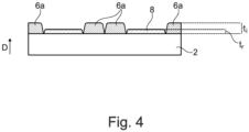
- Figure 4 shows an embodiment in which two insulator elements 6a next to each other together form an insulator element 6.
- a number of insulator elements 6a may form the insulator element 6.
- the thickness t i of the insulator element 6 is larger than the thickness t, of the resistive trace 8.
- Figure 5 shows embodiments having a coating 9.
- the coating 9 is provided on top of the insulator element 6 and the (most of the) remaining resistor structure 1.
- the coating 9 has a thickness between 1 ⁇ m and 200 ⁇ m and is substantially uniform.
- the thickness t c of the coating 9 varies less than about 10% among the coating 9.
- the coating is provided on top of the resistive traces 8 and the neighbored insulator element 6.
- the insulator element 6 is below the coating 9 and may be regarded as "buried” or “hidden” underneath the coating 9.
- the insulator element 6 may no longer be discernible from the coating 9. What remains discernible may be the total thickness of the combination of the coating 9 and of the insulator element 6 in the thickness direction D.
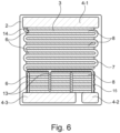
- Figure 6 shows a voltage divider arrangement 5 having a flat substrate 2.
- An insulator element 6 is provided next to a junction element 14 which connects the beginning of the resistive path 3 with the first terminal 4-1.
- an interconnecting element 13 which connects a plurality of resistive traces 8 to the terminal, here to the third terminal 4-3, an insulator element 6 is provided.
- the insulator elements 6 basically run perpendicular to the interconnecting element 13.
- an interconnecting path 15 connecting at least an end of a first resistive path 3-1 and a second resistive path 3-2 and a terminal, here the second terminal 4-2, insulator elements 6 are provided.
- These insulator elements 6 run at least partially parallel to the interconnecting path 15 and at least partially perpendicular to the interconnecting path 15. All insulator elements 6 of the voltage divider arrangement 5 may be identical and positioned parallel to each other.
- Figure 7 shows a voltage divider arrangement 5 with a cylindrical substrate 2 and a helix-shaped resistive path 3.
- the path 3 comprises a first resistive path 3-1 of a highohmic resistor 11, and a second resistive path 3-2 of a low-ohmic resistor 12, which are connected in series.
- the first terminal 4-1 is located opposite to the second 4-2 and third 4-3 terminals.
- Figure 7 further shows a junction element 14 for connecting a trace 8 and the first terminal 4-1, and transition elements 7 connecting two subsequent resistive traces 8 with each other.
- the coating 9 is present.
- a coating 9 of the invention may be added.
- a coating 9 may be an insulating coating having a thickness of about 1 to 200 ⁇ m, preferably 1 to 100 ⁇ m.
- the coating 9 may be made of an insulating material and of the same material as the insulator element 6 of the invention. It is possible that, in the final product, the coating 9 and an insulator element 6 of the invention are hardly discernible or are not discernible.
- the insulator element 6 may be a film.
- the insulator element 6 may be formed by a stack of a plurality of films which are provided on top of each other.
- Any insulator element 6 of the invention may be made of an inorganic insulating material.
- the dielectric strength of the insulator element 6 is typically higher than the dielectric strength of the insulating substrate 2 and/or the dielectric constant and/or the coefficient of thermal expansion of the insulator element 6 is substantially the same as of the insulating substrate 2.
- a resistor structure 1 of the invention may be deposited by screen printing. This can be done before or after deposition of the resistive traces 8.
Landscapes
- Engineering & Computer Science (AREA)
- Microelectronics & Electronic Packaging (AREA)
- Physics & Mathematics (AREA)
- Electromagnetism (AREA)
- Non-Adjustable Resistors (AREA)
Abstract
The invention relates to a resistor structure comprising at least an electrically insulating substrate, at least one electrically conductive terminal directly or indirectly provided on the substrate, at least one resistive path comprising at least one resistive trace directly or indirectly provided on the substrate and directly or indirectly joined to the terminal, wherein a thickness of the resistive trace is the thickness of the resistive trace in the thickness direction facing away from the substrate, characterized in that at least one insulator element is applied directly or indirectly and at least partially on the substrate , wherein a thickness of the insulator element is the thickness of the insulator element in the thickness direction facing away from the substrate.
Description
- The present invention concerns a resistor structure and a voltage divider arrangement as well as electric devices comprising such resistor structure and/or voltage divider arrangement.
- Resistor structures and voltage divider arrangements are configured for high voltage applications, for example between 500 V and 1000 kV. Resistors which are employed at high voltages feature a high resistance to limit power dissipation, e.g. larger than 100 kΩ.
- Resistor structures may comprise an electrically insulating substrate, at least one electrically conductive terminal applied on the substrate, and at least one resistive path applied on the substrate and joined to the terminal.
- A voltage divider arrangement may, in its simplest embodiment, comprise two resistor structures electrically connected in series for transforming a high voltage, so-called primary voltage, to a lower voltage, so-called secondary voltage. The secondary voltage is significantly smaller than the primary voltage, e.g. by a voltage divider ratio between 10 to 100 000. In more complex embodiments of a voltage divider, one or both of the serial resistor structures may be replaced by resistive networks. The resistors or corresponding resistor networks may be referred to as high and low ohmic resistors, respectively.
- These devices may be integrated in electrical devices, in which in particular severe operating conditions such as strong voltage overloads, power overloads, temperature variations, humidity variations, mechanical stresses and shocks may occur. Example electric devices are electronic instrument transformers (sensors), such as the KEVCD and KEVA sensor types of ABB, which are commonly employed in electrical power systems with a rated primary voltage between 7.2 kV and 48 kV.
-
US 9, 299, 484 B2 - High voltage applications typically require particular engineering efforts, to ensure both functionality and safety. The reason is that such resistor structures are exposed to a high electric field intensity, typically imposing excessive electric stresses. This may result in dielectric failures, like partial discharge or electrical breakdown.
- Therefore, it is desired to improve resistor structures and voltage divider arrangements as to manufacture, reliability and safety.
- The inventions relates to a resistor structure comprising at least an electrically insulating substrate, at least one, preferably two electrically conductive terminals directly or indirectly provided on the substrate, at least one resistive path comprising at least one resistive trace (optionally in parts) directly or indirectly provided on the substrate and directly or indirectly joined to the terminal, wherein a thickness of the resistive trace is the thickness of the resistive trace in the thickness direction facing away from the substrate. At least one insulator element is directly or indirectly applied on a part of the substrate, wherein a thickness of the insulator element is the thickness of the insulator element in the thickness direction facing away from the substrate, and at least a part of the insulator element and a part of the resistive path/trace are arranged at least partially adjacent to each other and such that
- (a) if the resistive trace/path is substantially free of a coating of a thickness between 1 µm and 200 µm, preferably 1 and 100 µm, optionally substantially free of any coating, the thickness of the insulator element is at least 30% of the thickness of the resistive trace/path, optionally larger than the thickness of the resistive trace/path,
and/or - (b) if the resistive trace/path is substantially covered by an insulating coating having a thickness between 1 µm and 200 µm, preferably 1 and 100 µm, a total thickness of the insulator element and the insulating coating exceeds the thickness of the insulating coating on the resistive trace, optionally by at least 30%.
- The present invention may alternatively or additionally be characterized as follows, see (a) above: The thickness of the insulator element is larger than a specific percentage of the thickness of the resistive trace, where at least 50% of the width of the trace is not covered by the insulator element.
- The present invention may alternatively or additionally be characterized as follows, see (b) above: The thickness of the insulator element (or film) aside the resistive trace is larger than the thickness of the insulator element atop the resistive trace by at least the specific percentage of the thickness of the resistive trace.
- The specific percentage of the thickness of the resistive trace may be at least 30%, preferably at least 50%, and more preferably at least 100%.
- According to the invention, an electrically insulating, i.e. insulator element is provided. The insulator element is provided adjacent, i.e. next, to at least a part of the resistive trace or path. The insulator element and the resistive trace are at least partially next to each other, when viewed along the surface of the substrate.
- An insulator element of the invention may be regarded as filling at least partially gaps or voids next to resistive traces with additional insulating material.
- If the resistive trace is substantially not covered by a coating and/or insulation, the trace can be seen as substantially free of coating. This does not exclude that edge portions of the resistive trace are overlapped by insulation, such as a part of the insulator element. For example, insulator elements/coatings may not join each other on top of a resistive trace, if the resistive trace is substantially not covered by a coating and/or insulation.
- In some embodiments, the resistive path may be seen as sunk below the insulator element. In some embodiments, at least the exposure of the resistive path to outer influences and mechanical stresses may be reduced. In some embodiments, the insulator element may protrude from the resistive path in the direction facing away from the substrate. In some embodiments, the insulator thickness may be at least 30% of the thickness of the resistive trace.
- The insulator element may protect edges of the resistive path. The insulator element may, alternatively or additionally, protect the top of at least a part of the resistive path against mechanical stresses. Additionally or alternatively, an insulator element of the invention may improve the electrical insulation relative to the resistive path. This may reduce related degradations and resistance drifts. This may, in turn, lead to improved accuracy and reliability, allowing for higher operating voltage and, at the same time, a smaller size of the resistor structure and voltage divider.
- Accordingly, the accuracy and the voltage withstand of the resistor structure and of the corresponding voltage divider arrangement may be enhanced.
- Resistive materials commonly employed in thick film technology are based on formulations mainly comprising glass, particles of conductive oxide ceramic such as ruthenium oxide, and possibly other additives such as metal particles. Thick film resistive materials or films have a resistivity (sheet resistance) usually between 50 mΩ/square and 1 GΩ/square.
- In the context of the invention, a resistive trace of the resistive path is made of a resistive material with resistivity preferably between 50 Ω/square and 100 MΩ/square, or preferably between 500 Ω/square and 10 MΩ/square. Non-exhaustive examples of possible resistive materials are the R8700 Series from Heraeus or the 2000 Series from DuPont.
- Electrically conductive materials commonly employed in thick film technology are based on formulations comprising a major amount of metal particles like Ag, Pd, Au, Pt and possibly other additives. Thick film conductor materials or films have a resistivity usually comprised between 1 mΩ/square and 1 Ω/square. Non-exhaustive examples of possible conductive materials are the C2210 from Heraeus or the 7484 from DuPont.
- An insulator material is seen as having a volume resistivity larger than 107 Ω·cm.
- The resistive path comprises one or more resistive traces. If more resistive traces are provided, the resistive traces may be connected directly or indirectly and at least partly in series or in parallel.
- Optionally, the resistive path comprises resistive traces which are electrically connected in series by transition elements to form the resistive path. Resistive traces may, at least partially, run parallel to each other.
- Optionally, according to (b), the insulating coating at least partially covers the resistive path and/or the insulator element. Alternatively, the insulating coating may cover almost the entire substrate.
- Optionally, according to (b), the coating is made of the same material as the insulator element and/or wherein the thickness of the coating varies less than about 10% among the coating or is substantially uniform.
- Optionally, the insulator element comprises a number of insulator element parts, which are optionally distanced from each other, and/or have substantially the same geometry as the at least one resistive trace of the resistive path, wherein further optionally each insulator part is in the form of preferably parallel stripes. Such realizations allow for efficient manufacture.
- Optionally, at least one insulator element is positioned alongside at least a part of the resistive path, optionally running in parallel to at least a part of the resistive trace. This allows for effective protection of the resistive path by way of the insulator element.
- Optionally, at least one insulator element is positioned perpendicular to a part of the resistive path, optionally at a turnaround, corner or termination of the resistive path, further optionally outside the resistive path. Such arrangement provides for effective protection of the insulator element at sensitive regions of the resistive path.
- Optionally, at least a part of a resistive trace is sandwiched between two insulator elements. This means that the part of the resistive trace is bordered at each lateral side by an insulator element. Protection from two sides, in particular from opposite sides, allows for effective protection of the resistive path.
- Optionally, an edge part of the resistive trace and a part of the insulator element overlap in the thickness direction. Further optionally, the insulator element at least partially overlaps the edge of the resistive path, so as to cover and protect the edge.
- Optionally, a distance between the resistive trace and the insulator element is less than 25% of the width of the resistive trace and/or less than 150 µm. Providing the insulator element relatively closely to the resistive path may improve the protection.
- Optionally, the insulator element is made of an inorganic insulating material comprising glass or ceramics and/or has a denser structure (less or thinner grain boundaries and/or smaller voids) than the insulating substrate. This may allow for improved dielectric strength of the insulator element.
- The width of the insulator element (part) may be approximately equal to or preferably smaller than that of a resistive trace. This may allow to exploit more efficiently the benefits of an insulator element, for example by reducing the useage of other matrials employed for manufacturing the resistor structure.
- Optionally, the dielectric strength of the insulator element is higher than the dielectric strength of the insulating substrate and/or the dielectric constant and/or the coefficient of thermal expansion of the insulator element is substantially the same as of the insulating substrate. This mayimprove the dielectric strength and the reliability of the resistor structure.
- Optionally, the insulator element is a film, optionally a stack of films. One or more films allow for efficient application and integration into the manufacturing process.
- Optionally, the insulator element is deposited by screen printing or direct printing through a nozzle, before or after deposition of the resistive path. This supports efficient manufacture.
- Optionally, the insulator element is provided next to a junction element connecting the terminal, and/or next to an interconnecting element connecting at least two resistive traces of the resistive path and a portion of the terminal, and/or next to an interconnecting path connecting at least an end of a first resistive path and an end of a second resistive path and the portion of the terminal, wherein the resistive path comprises at least the first and second resistive paths. These locations may render the protection by way of an insulation element more effective.
- Resistor structures of the invention may be manufactured using thick film technology, e.g. screen printing or stencil printing or direct printing through a nozzle. Films of conductive material and of resistive material are sequentially deposited on an insulating substrate. Typically, a single layer of a single material is deposited, followed by a subsequent step such as drying or firing. For example, conductive film or a resistive film are fired at a very high temperature, between 600°C and 950°C.
- The insulating substrate may be made of ceramic material, such as aluminum oxide or aluminum nitride. The insulating substrate may be in the form of a flat, planar sheet or, alternatively, in the form of a cylinder.
- In addition to the first electrically conductive terminal, at least a second electrically conductive terminal may be typically provided in a resistive structure, wherein the resistive path connects to the first and second terminals. In a voltage divider, the high and low-ohmic resistors may share a terminal, so that a voltage divider arrangement may comprise at least first, second and third terminals.
- The resistive path may comprise, in addition to the at least first resistive path, a second resistive path, wherein the paths are connected in series. A resistive path (or the resistive paths) may at least partially be in the form of a helix. Hence, the resistive path may at least partially run helically.
- A coating made of an electrically insulating material may be provided. In some embodiments, the coating may be the outermost entity or layer. The coating may cover the entire resistive structure or partially. The coating may cover at least part of the resistive path and possibly part(s) of the terminal(s). A part of each terminal is preferably not covered by the coating in order to provide electrical connection(s) to the resistive structure. The coating may be a film and may be made of a thickness between 5 to 100 µm and/or between 3 to 30 µm. The coating film may have different thicknesses, optionally a first thickness being between 5 and 100 µm, and a second thickness being between 3 and 30 µm, where the first thickness is larger than the second thickness by at least 50% or at least 5 µm.
- Optionally, a second coating, e.g. made of a polymer, may be applied on a first coating. The second coating may be thicker than the first coating.
- A shunt may be provided. A shunt section is configured to shunt a distinct portion of a resistive trace to proportionally reduce its effective resistive length. This may mean that the length which is electrically effective (and, thus, determines the electrical resistance of the trace ) is shorter than the actual length of the trace. A transition element may shunt section. A shunt section has a lower resistivity than the resistive trace to which the shunt section (e.g. transition element) is connected to.
- Optionally, the resistor structure comprises resistive traces being mainly identical and being preferably arranged periodically with mainly a same pitch. The resistive traces may be made of a same resistive material, and may have mainly a same thickness, width, slope, and (actual) length. This helps for efficient and reproducible manufacturing of the resistive traces and of the resistive path.
- A voltage divider arrangement of the invention may comprise a high ohmic resistor and a low ohmic resistor electrically connected in series, where the voltage divider arrangement comprises at least one resistor structure of the invention. The high ohmic resistor is made of one or more resistive traces and the low ohmic resistor is made of one or more resistive traces, and the high ohmic and the low ohmic resistors differ as to their resistance.
- Optionally, the voltage divider arrangement is provided on the same substrate and comprises resistive traces being substantially identical, and insulator elements being substantially identical, wherein preferably the resistive traces and the insulator elements are arranged substantially in a periodic manner. This may provide an arrangement which is more effective to manufacture and less prone to failure.
- An electrical device of the invention comprises a resistor structure or a voltage divider arrangement of the invention.
-
-
Figure 1 shows a schematic plan view of a resistor structure of the invention. -
Figure 2 shows a top view of a plan resistor structure the invention. -
Figure 3 shows cross-sectional views of a resistor structure of the invention, whereinfigures 3(a) to (d) show different embodiments. -
Figure 4 shows a cross-sectional view of another resistor structure of the invention. -
Figure 5 shows cross-sectional views of resistor structures of the invention, whereinfigures 5(a) and (b) refer to different embodiments. -
Figure 6 shows a voltage divider arrangement in a plan view. -
Figure 7 shows a voltage divider arrangement having a cylindrical substrate in perspective views, whereinfigures 7(a) and (b) show views from different angles. -
Figure 1 schematically shows aresistor structure 1 having first 4-1 and second 4-2 terminals. The terminals are provided on asubstrate 2. Further, aresistive path 3 is applied onto thesubstrate 2. Theresistive path 3 runs between the first 4-1 and second 4-2 terminals. Aninsulator element 6 having two parts in the embodiment offigure 1 is located next, i.e. adjacent or neighbored, to theresistive path 3. As shown in this example, theinsulator element 6 may laterally sandwich at least a part of theresistive path 3, so as to improve the protection of theresistive path 3 by theinsulator element 6. -
Figure 2 shows aplan resistor structure 1 and details as to theresistive path 3 and theinsulator element 6. Specifically, theresistive path 3 comprises at least oneresistive trace 8 formingturnarounds 10.Various parts 6a of theinsulator element 6 are shown in the embodiment offigure 2 . More specifically, theparts 6a of the insulator element are distanced from each other. Theinsulator elements 6a may have the same geometry, namely stripes in the embodiment offigure 2 . These stripes run parallel to each other and parallel to the resistive traces 8. Eachresistive trace 8 may be seen as laterally sandwiched between twoinsulator elements 6. Furtherinsulator element parts 6a, also in the form of stripes, are positioned perpendicular to the run of theresistive traces 8 positioned adjacent to theturnarounds 10. Theseparts 6a are provided outside theresistive path 3 and embrace the entireresistive path 3 inbetween. -
Figure 3 shows embodiments of aresistor structure 1 of the invention, wherein theresistive trace 8 as well as most of the remainingresistor structure 1 is free of any coating. The thickness is indicated with respect to the thickness direction D, namely the direction which faces away from thesubstrate 2. The thickness ti of theinsulator element 6 is at least 30% of the thickness t, of theresistive trace 8. Infigure 3(a) , for example, the thickness ti of the insulatingelement 6 is larger than the thickness t, of theresistive trace 8. Infigure 3(b) , theinsulator element 6 has a thickness ti which is larger than the thickness tr of the resistive trace, wherein the edges of theresistive trace 8 are overlapped by theinsulator element 6. As shown infigure 3(c) , at one edge of theresistive trace 8, theinsulator element 6 overlaps theresistive trace 8. A part of theresistive path 3 and a part of theinsulator element 6, accordingly, overlap in the thickness direction D. On the opposite edge of theresistive trace 8 in the width direction of theresistive trace 8, there is no overlap between theinsulator element 6 and theresistive trace 8. Rather, infigure 3(c) , a gap can be identified. A distance between theresistive trace 8 and theadjacent insulator element 6 may be less than 25% of the width of theresistive trace 8 and/or less than 150 µm.Figure 3(d) shows an embodiment in which theinsulator element 6 is thicker than theresistive trace 8, wherein theinsulator element 6 has indentations near the overlap with theresistive trace 8. -
Figure 4 shows an embodiment in which twoinsulator elements 6a next to each other together form aninsulator element 6. A number ofinsulator elements 6a may form theinsulator element 6. In this example, the thickness ti of theinsulator element 6 is larger than the thickness t, of theresistive trace 8. -
Figure 5 shows embodiments having acoating 9. Thecoating 9 is provided on top of theinsulator element 6 and the (most of the) remainingresistor structure 1. Thecoating 9 has a thickness between 1 µm and 200 µm and is substantially uniform. The thickness tc of thecoating 9 varies less than about 10% among thecoating 9. As shown infigure 5(a) , the coating is provided on top of theresistive traces 8 and the neighboredinsulator element 6. Theinsulator element 6 is below thecoating 9 and may be regarded as "buried" or "hidden" underneath thecoating 9. Theinsulator element 6 may no longer be discernible from thecoating 9. What remains discernible may be the total thickness of the combination of thecoating 9 and of theinsulator element 6 in the thickness direction D. The thickness tti of thecoating 9 plus the thickness of theinsulator element 6 in total corresponds at least to the thickness of the insulation next to theresistive trace 8. This total thickness tti exceeds the thickness tc of the insulatingcoating 9 on top of theresistive trace 8. On top of theresistive trace 8, only the insulatingcoating 9, but noinsulator element 6 of the invention is provided. Theinsulator element 6 can, accordingly, e.g. contribute to a levelling of the overall surface by reducing the difference in height between parts of thecoating 9 under which aresistive trace 8 is formed and under which noresistive trace 8 is formed. -
Figure 5(b) shows an embodiment in which the thickness ti of theinsulator element 6 exceeds the thickness tr of theresistive trace 8. Also, the total thickness tti of the combination of theinsulator element 6 and of the insulatingcoating 9 exceeds the thickness tc of the insulatingcoating 9 on theresistive trace 8 by at least 30%, here by about 300%. In this embodiment, as the height/thickness of theinsulator element 6 exceeds the height/thickness of theresistive trace 8, theresistive trace 8 is protected by theinsulator element 6 protruding from the remainingsubstrate 2. -
Figure 6 shows a voltage divider arrangement 5 having aflat substrate 2. Aninsulator element 6 is provided next to ajunction element 14 which connects the beginning of theresistive path 3 with the first terminal 4-1. Further, next to an interconnectingelement 13 which connects a plurality ofresistive traces 8 to the terminal, here to the third terminal 4-3, aninsulator element 6 is provided. Theinsulator elements 6 basically run perpendicular to the interconnectingelement 13. Further, next to an interconnectingpath 15 connecting at least an end of a first resistive path 3-1 and a second resistive path 3-2 and a terminal, here the second terminal 4-2,insulator elements 6 are provided. Theseinsulator elements 6 run at least partially parallel to the interconnectingpath 15 and at least partially perpendicular to the interconnectingpath 15. Allinsulator elements 6 of the voltage divider arrangement 5 may be identical and positioned parallel to each other. -
Figure 7 shows a voltage divider arrangement 5 with acylindrical substrate 2 and a helix-shapedresistive path 3. Thepath 3 comprises a first resistive path 3-1 of a highohmic resistor 11, and a second resistive path 3-2 of a low-ohmic resistor 12, which are connected in series. The first terminal 4-1 is located opposite to the second 4-2 and third 4-3 terminals.Figure 7 further shows ajunction element 14 for connecting atrace 8 and the first terminal 4-1, andtransition elements 7 connecting two subsequentresistive traces 8 with each other. - In the embodiments shown in
figures 1 to 4 , no coating is provided. Also, the embodiments offigure 6 and7 are free of coating. However, in the embodiment offigure 5 , thecoating 9 is present. To any of the embodiments of the invention, acoating 9 of the invention may be added. Also, it is conceivable that a so-called conformal coating having a thickness of about 1 mm may be added. Acoating 9 may be an insulating coating having a thickness of about 1 to 200 µm, preferably 1 to 100 µm. Hence, a conformal coating differs from thecoating 9 of the invention. Thecoating 9 may be made of an insulating material and of the same material as theinsulator element 6 of the invention. It is possible that, in the final product, thecoating 9 and aninsulator element 6 of the invention are hardly discernible or are not discernible. - In any of the embodiments, the
insulator element 6 may be a film. Optionally, theinsulator element 6 may be formed by a stack of a plurality of films which are provided on top of each other. - Any
insulator element 6 of the invention may be made of an inorganic insulating material. The dielectric strength of theinsulator element 6 is typically higher than the dielectric strength of the insulatingsubstrate 2 and/or the dielectric constant and/or the coefficient of thermal expansion of theinsulator element 6 is substantially the same as of the insulatingsubstrate 2. Aresistor structure 1 of the invention may be deposited by screen printing. This can be done before or after deposition of the resistive traces 8. -
- 1 resistor/resistive structure
- 2 electrically insulating substrate
- 3 resistive path
- 3-1 first resistive path
- 4 terminal
- 4-1 first terminal
- 4-2 second terminal
- 4-3 third terminal
- 6 insulator element
- 6a part of insulator element
- 7 transition element
- 8 resistive trace
- 9 coating
- 10 turnaround of resistive path
- 11 high ohmic resistor
- 12 low ohmic resistor
- 13 interconnecting element
- 14 junction element
- 15 interconnecting path
- ti thickness of insulator element
- t, thickness of resistive trace
- tti total thickness of insulation on top of substrate
- tc thickness of coating
- D thickness direction
Claims (17)
- Resistor structure (1) comprising at leastan electrically insulating substrate (2),at least one electrically conductive terminal (4) directly or indirectly provided on the substrate (2),at least one resistive path (3) comprising at least one resistive trace (8) directly or indirectly provided on the substrate (2) and directly or indirectly joined to the terminal (4), wherein a thickness (tr) of the resistive trace (8) is the thickness of the resistive trace (8) in the thickness direction (D) facing away from the substrate (2), characterized in thatat least one insulator element (6) is applied directly or indirectly and at least partially on the substrate (2), wherein a thickness (ti) of the insulator element is the thickness of the insulator element in the thickness direction (D) facing away from the substrate (2), and in thatat least a part of the insulator element (6) and a part of the resistive path (3) are arranged at least partially adjacent to each other and such that(a) if the resistive trace (8) is substantially free of a coating (9) of a thickness (tc) between 1 µm and 200 µm, preferably 1 and 100 µm, optionally substantially free of any coating, the thickness (ti) of the insulator element is at least 30% of the thickness (tr) of the resistive trace (8), optionally larger than the thickness (tr) of the resistive trace (8),
and/or(b) if the resistive trace (8) is substantially covered by an insulating coating (9) having a thickness (tc) between 1 µm and 200 µm, preferably 1 and 100 µm, a total thickness (tti) of the insulator element and of the insulating coating exceeds the thickness (tc) of the insulating coating (9) on the resistive trace (8), optionally by at least 30%. - Resistor structure of claim 1, wherein, according to (b), the insulating coating (9) at least partially covers the resistive path (3) and/or the insulator element (6) and/or is selectively applied.
- Resistor structure of claim 2, wherein, according to (b), the coating (9) is made of the same material as the insulator element (6).
- Resistor structure of any of the preceding claims, wherein the insulator element (6) comprises a number of insulator element parts (6a), which are optionally distanced from each other, and/or has substantially the same geometry as at least one resistive trace (8) of the resistive path (3), wherein further optionally each insulator part (6a) is in the form of preferably parallel stripes.
- Resistor structure of any of the preceding claims, wherein at least one insulator element (6) is positioned alongside at least a part of the resistive path (3), optionally running in parallel to at least a part of the resistive trace (8).
- Resistor structure of any of the preceding claims, wherein the resistive path is at least partly shaped like a helix and the insulator element is at least partially provided between turns of the resistive path and/or the insulator element is at least partly shaped like a helix.
- Resistor structure of any of the preceding claims, wherein at least a part of a resistive trace (8) is sandwiched between two insulator elements (6), when viewed along a surface parallel to the substrate (2).
- Resistor structure of any of the preceding claims, wherein an edge of the resistive trace (8) and a part of the insulator element (6) overlap in the thickness direction (D).
- Resistor structure of any of the preceding claims, wherein at least in part a distance between the resistive trace (8) and the insulator element (6) is less than 25% of the width of the resistive trace (8) and/or less than 150 µm.
- Resistor structure of any of the preceding claims, wherein the insulator element (6) is made of an inorganic insulating material comprising glass.
- Resistor structure of any of the preceding claims, wherein insulator element parts (6a) are interposed between resistive traces (8) and preferably between a resistive trace (8) and the terminal (4), where the insulator element part (6a) and the resistive trace (8) have preferably approximately equal length and slope.
- Resistor structure of any of the preceding claims, wherein the insulator element (6) is a film, optionally a stack of films.
- Resistor structure of any of the preceding claims, wherein the insulator element (6) is deposited by screen printing, before or after deposition of the resistive path (3).
- Resistor structure of any of the preceding claims, wherein the insulator element (6) is provided next to a junction element (14) connecting the terminal,
and/ornext to an interconnecting element (13) connecting at least two resistive traces (8) of the resistive path (3) and a portion of the terminal (4-2),
and/ornext to an interconnecting path (15) connecting at least an end of a first resistive path (3-1) and an end of a second resistive path (3-2) and the portion of the terminal (4-2), wherein the resistive path (3) comprises at least the first (3-1) and second (3-2) resistive paths. - Voltage divider arrangement (5) for electrical power systems for transformation of voltage, the voltage divider arrangement comprising a first resistor structure (1) of any of the preceding claims, and a second resistor structure (1), optionally of any of the preceding claims, wherein the first and second resistor structures are connected in series and the first and second resistor structures differs as to their resistance.
- Voltage divider arrangement of claim 15, which is provided on the same substrate (2) and comprises resistive traces (8) being substantially identical and substantially insulator elements being substantially identical, wherein preferably the resistive traces (8) and the insulator elements (6) are arranged substantially in a periodic manner.
- Electrical device comprising the resistor structure (1) and/or the voltage divider arrangement (5) of any of the preceding claims.
Priority Applications (3)
| Application Number | Priority Date | Filing Date | Title |
|---|---|---|---|
| EP23210185.7A EP4557319A1 (en) | 2023-11-15 | 2023-11-15 | Resistor structure and a voltage divider arrangement |
| US18/946,822 US20250157701A1 (en) | 2023-11-15 | 2024-11-13 | Resistor Structure and a Voltage Divider Arrangement |
| CN202411633925.XA CN120015446A (en) | 2023-11-15 | 2024-11-15 | Resistor Structure and Voltage Divider Arrangement |
Applications Claiming Priority (1)
| Application Number | Priority Date | Filing Date | Title |
|---|---|---|---|
| EP23210185.7A EP4557319A1 (en) | 2023-11-15 | 2023-11-15 | Resistor structure and a voltage divider arrangement |
Publications (1)
| Publication Number | Publication Date |
|---|---|
| EP4557319A1 true EP4557319A1 (en) | 2025-05-21 |
Family
ID=88837203
Family Applications (1)
| Application Number | Title | Priority Date | Filing Date |
|---|---|---|---|
| EP23210185.7A Pending EP4557319A1 (en) | 2023-11-15 | 2023-11-15 | Resistor structure and a voltage divider arrangement |
Country Status (3)
| Country | Link |
|---|---|
| US (1) | US20250157701A1 (en) |
| EP (1) | EP4557319A1 (en) |
| CN (1) | CN120015446A (en) |
Citations (5)
| Publication number | Priority date | Publication date | Assignee | Title |
|---|---|---|---|---|
| GB735889A (en) * | 1952-11-06 | 1955-08-31 | George Victor Planer | Improvements in or relating to electrical resistors |
| US20090243788A1 (en) * | 2008-03-27 | 2009-10-01 | Jack Chen | Fan Resistor |
| EP2678869A2 (en) * | 2011-02-25 | 2014-01-01 | Abb Ag | Resistive structure and resistive voltage divider arrangement |
| US20190172614A1 (en) * | 2016-08-10 | 2019-06-06 | Koa Corporation | Coil resistor and method for manufacturing same |
| US20210398717A1 (en) * | 2018-11-05 | 2021-12-23 | Koa Corporation | Noise-preventing resistor and method of manufacturing same |
-
2023
- 2023-11-15 EP EP23210185.7A patent/EP4557319A1/en active Pending
-
2024
- 2024-11-13 US US18/946,822 patent/US20250157701A1/en active Pending
- 2024-11-15 CN CN202411633925.XA patent/CN120015446A/en active Pending
Patent Citations (6)
| Publication number | Priority date | Publication date | Assignee | Title |
|---|---|---|---|---|
| GB735889A (en) * | 1952-11-06 | 1955-08-31 | George Victor Planer | Improvements in or relating to electrical resistors |
| US20090243788A1 (en) * | 2008-03-27 | 2009-10-01 | Jack Chen | Fan Resistor |
| EP2678869A2 (en) * | 2011-02-25 | 2014-01-01 | Abb Ag | Resistive structure and resistive voltage divider arrangement |
| US9299484B2 (en) | 2011-02-25 | 2016-03-29 | Abb Ag | Resistive structure and resistive voltage divider arrangement |
| US20190172614A1 (en) * | 2016-08-10 | 2019-06-06 | Koa Corporation | Coil resistor and method for manufacturing same |
| US20210398717A1 (en) * | 2018-11-05 | 2021-12-23 | Koa Corporation | Noise-preventing resistor and method of manufacturing same |
Also Published As
| Publication number | Publication date |
|---|---|
| CN120015446A (en) | 2025-05-16 |
| US20250157701A1 (en) | 2025-05-15 |
Similar Documents
| Publication | Publication Date | Title |
|---|---|---|
| US8760830B2 (en) | ESD protection device | |
| US8724284B2 (en) | Electrostatic protection component | |
| US7420795B2 (en) | Multilayer capacitor | |
| US7646586B2 (en) | Multilayer capacitor and method of manufacturing same | |
| KR101415477B1 (en) | Paste for electrostatic protection, electrostatic protection component, and method for producing same | |
| CN103460308B (en) | Resistive voltage divider made of a resistive film material on an insulating substrate | |
| US7995327B2 (en) | Film, a capacitor, a voltage transformer and a method of using a capacitor | |
| US11152141B2 (en) | Ceramic multi-layer component and method for producing a ceramic multi-layer component | |
| US8730648B2 (en) | Electrical component | |
| US20110317328A1 (en) | Ceramic electronic component and method for manufacturing the same | |
| KR101832185B1 (en) | Wiring substrate and temperature sensing element | |
| EP4557319A1 (en) | Resistor structure and a voltage divider arrangement | |
| CN120019261A (en) | Sensor element and method for producing a sensor element | |
| CN114207746B (en) | NTC thermistor element | |
| JP4000633B2 (en) | Wiring board manufacturing method | |
| EP4557320A1 (en) | Resistor structure and a voltage divider arrangement | |
| EP4557318A1 (en) | Resistor structure and a voltage divider arrangement | |
| EP4557321A1 (en) | Resistor structure and a voltage divider arrangement | |
| US11626219B2 (en) | Chip resistor and method for manufacturing same | |
| JPH06314602A (en) | Ceramic electronic component | |
| JP2001126901A (en) | Chip component | |
| US20250174380A1 (en) | Multilayer varistor | |
| US11961678B2 (en) | Film capacitor device | |
| US20200168373A1 (en) | Varistor | |
| KR19990044154A (en) | Low Ohmic Chip Resistors |
Legal Events
| Date | Code | Title | Description |
|---|---|---|---|
| PUAI | Public reference made under article 153(3) epc to a published international application that has entered the european phase |
Free format text: ORIGINAL CODE: 0009012 |
|
| STAA | Information on the status of an ep patent application or granted ep patent |
Free format text: STATUS: THE APPLICATION HAS BEEN PUBLISHED |
|
| AK | Designated contracting states |
Kind code of ref document: A1 Designated state(s): AL AT BE BG CH CY CZ DE DK EE ES FI FR GB GR HR HU IE IS IT LI LT LU LV MC ME MK MT NL NO PL PT RO RS SE SI SK SM TR |
|
| STAA | Information on the status of an ep patent application or granted ep patent |
Free format text: STATUS: REQUEST FOR EXAMINATION WAS MADE |
|
| 17P | Request for examination filed |
Effective date: 20251117 |