EP4557230A2 - Systems and methods for lean ortho correction for computer models of structures - Google Patents
Systems and methods for lean ortho correction for computer models of structures Download PDFInfo
- Publication number
- EP4557230A2 EP4557230A2 EP25160745.3A EP25160745A EP4557230A2 EP 4557230 A2 EP4557230 A2 EP 4557230A2 EP 25160745 A EP25160745 A EP 25160745A EP 4557230 A2 EP4557230 A2 EP 4557230A2
- Authority
- EP
- European Patent Office
- Prior art keywords
- image
- world
- point
- lean
- model
- Prior art date
- Legal status (The legal status is an assumption and is not a legal conclusion. Google has not performed a legal analysis and makes no representation as to the accuracy of the status listed.)
- Pending
Links
Images

Classifications
-
- G—PHYSICS
- G06—COMPUTING OR CALCULATING; COUNTING
- G06F—ELECTRIC DIGITAL DATA PROCESSING
- G06F30/00—Computer-aided design [CAD]
- G06F30/10—Geometric CAD
- G06F30/13—Architectural design, e.g. computer-aided architectural design [CAAD] related to design of buildings, bridges, landscapes, production plants or roads
-
- G—PHYSICS
- G06—COMPUTING OR CALCULATING; COUNTING
- G06T—IMAGE DATA PROCESSING OR GENERATION, IN GENERAL
- G06T17/00—Three-dimensional [3D] modelling for computer graphics
- G06T17/05—Geographic models
-
- G—PHYSICS
- G06—COMPUTING OR CALCULATING; COUNTING
- G06T—IMAGE DATA PROCESSING OR GENERATION, IN GENERAL
- G06T17/00—Three-dimensional [3D] modelling for computer graphics
- G06T17/20—Finite element generation, e.g. wire-frame surface description, tesselation
-
- G—PHYSICS
- G06—COMPUTING OR CALCULATING; COUNTING
- G06T—IMAGE DATA PROCESSING OR GENERATION, IN GENERAL
- G06T19/00—Manipulating three-dimensional [3D] models or images for computer graphics
- G06T19/20—Editing of three-dimensional [3D] images, e.g. changing shapes or colours, aligning objects or positioning parts
-
- G—PHYSICS
- G06—COMPUTING OR CALCULATING; COUNTING
- G06T—IMAGE DATA PROCESSING OR GENERATION, IN GENERAL
- G06T2200/00—Indexing scheme for image data processing or generation, in general
- G06T2200/24—Indexing scheme for image data processing or generation, in general involving graphical user interfaces [GUIs]
-
- G—PHYSICS
- G06—COMPUTING OR CALCULATING; COUNTING
- G06T—IMAGE DATA PROCESSING OR GENERATION, IN GENERAL
- G06T2207/00—Indexing scheme for image analysis or image enhancement
- G06T2207/10—Image acquisition modality
- G06T2207/10032—Satellite or aerial image; Remote sensing
-
- G—PHYSICS
- G06—COMPUTING OR CALCULATING; COUNTING
- G06T—IMAGE DATA PROCESSING OR GENERATION, IN GENERAL
- G06T2207/00—Indexing scheme for image analysis or image enhancement
- G06T2207/30—Subject of image; Context of image processing
- G06T2207/30181—Earth observation
- G06T2207/30184—Infrastructure
-
- G—PHYSICS
- G06—COMPUTING OR CALCULATING; COUNTING
- G06T—IMAGE DATA PROCESSING OR GENERATION, IN GENERAL
- G06T2219/00—Indexing scheme for manipulating 3D models or images for computer graphics
- G06T2219/20—Indexing scheme for editing of 3D models
- G06T2219/2004—Aligning objects, relative positioning of parts
-
- G—PHYSICS
- G06—COMPUTING OR CALCULATING; COUNTING
- G06T—IMAGE DATA PROCESSING OR GENERATION, IN GENERAL
- G06T2219/00—Indexing scheme for manipulating 3D models or images for computer graphics
- G06T2219/20—Indexing scheme for editing of 3D models
- G06T2219/2016—Rotation, translation, scaling
-
- G—PHYSICS
- G06—COMPUTING OR CALCULATING; COUNTING
- G06T—IMAGE DATA PROCESSING OR GENERATION, IN GENERAL
- G06T2219/00—Indexing scheme for manipulating 3D models or images for computer graphics
- G06T2219/20—Indexing scheme for editing of 3D models
- G06T2219/2021—Shape modification
Definitions
- the present disclosure relates generally to the fields of computer vision and photogrammetry. More specifically, the present disclosure relates to systems and methods for lean ortho correction for computer models of structures
- the system includes a transformation module which adjusts projections of computer models onto images that suffer from leaning and/or distortions present in the images, so that the images are still useful in generating and/or refining existing computer models of structures.
- the system displays a projection of a computer model onto an orthorectified image that suffers from leaning, and the user determines two world three-dimensional (3D) points in the image such that the second world 3D point has a height which is different than the height of the first world 3D point, and a third point where the second world 3D point is actually displayed in the image.
- 3D three-dimensional
- the points can be identified by a user using a graphical user interface and an associated input device, or automatically using suitable computer vision techniques capable of identifying the points.
- the system transforms the coordinates of the model points using a lean ortho correction algorithm, and re-projects the model onto the orthorectified image so that the projected model more accurately aligns with features of the orthorectified image.
- the present disclosure relates to systems and methods for lean ortho correction for computer models of structures, as discussed in detail below in connection with FIGS. 1-5 .
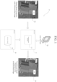
- FIG. 1 is a diagram illustrating the system of the present disclosure, indicated generally at 10.
- the system 10 includes a transformation module 12 that is executed by a processor 14 and which processes a structure model 22 stored in a memory 20 in communication with the processor 14, and a user interface 26 that communicates with the processor 14 and which can be operated by a user of the system 10.
- the structure model 22 could include a wireframe or polygonal model of a structure, such as a three-dimensional model of a house as shown.
- the system 10 rapidly transforms coordinates of the structure model 22 to better fit an orthorectified image 16 that suffers from leaning. As can be seen in FIG.
- points could be identified in the image 16 by the user using the user interface 26, or automatically through suitable computer vision techniques.
- the user interface 26 could include, but is not limited to, a display and associated keyboard and/or mouse, a touchscreen, lightpen, etc.
- the process steps of the invention disclosed herein could be embodied as computer-readable software code executed by one or more computer systems, and could be programmed using any suitable programming languages including, but not limited to, C, C++, C#, Java, Python, or any other suitable languages.
- the computer system(s) on which the present invention could be embodied include, but are not limited to, one or more personal computers, servers, mobile devices, cloud-based computing platforms, etc., each having one or more suitably powerful microprocessors and associated operating system(s) such as Linux, UNIX, Microsoft Windows, MacOS, etc. Still further, the invention could be embodied as a customized hardware component such as a field-programmable gate array (FPGA), application-specific integrated circuit (ASIC), embedded system, or other customized hardware component without departing from the spirit or scope of the present disclosure.
- FPGA field-programmable gate array
- ASIC application-specific integrated circuit
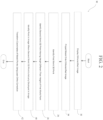
- FIG. 2 is a flowchart 30 illustrating processing steps carried out by the system of the present disclosure, and additionally with reference to FIGS. 3-5 .
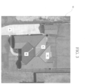
- the system displays an orthorectified image, such as the image 50 shown in FIG. 3 .
- the image 50 could be displayed on a screen of the user interface 26 of FIG. 1 , and suffers from leaning.
- the system projects a projection 52 computer model of the structure (house) shown in FIG. 3 onto the image 50. As can be seen in FIG.
- the projection 52 is a wireframe representation of the model, but not all features of the projected model match corresponding features in the image 50 due to the presence of lean in the image.
- the user identifies a first world three-dimensional (3D) point A shown in the image 50.
- the point A corresponds to a roof corner appearing on one corner of the roof of the building shown in the image 50.
- the user identifies a second world three-dimensional (3D) point B shown in the image 50 having an elevation (height) which is greater than the elevation (height) of point A.
- point B corresponds to one end of a roof ridge of the wireframe projection 52.
- step 40 the user identifies a point C in the image 50 where the second world point 3D point B actually appears in the image 50.
- point C in the image 50 shows the actual location of one end of the roof ridge that corresponds to the point B identified by the system.
- FIG. 4 shows an alternate set of points that could be identified and used by the system, in the image 50.
- point A is the first world 3D point corresponding to a different corner of the roof of the building shown in FIG. 4
- point B is the second world 3D point in the image having a height greater that the point A
- point C is a point identifying the actual location in the image 50 corresponding to point B.
- the points A, B, and C could be identified by a user pointing and clicking on the points in the image using a mouse and display of the user interface 26 of FIG. 1 , or automatically identified using computer vision techniques.
- classical computer vision approaches can be used for point detection, as well as more sophisticated systems based on deep neural networks architectures to locate keypoints.
- step 42 the system transforms the coordinates of the model using the points A, B, and C identified in the image 50 and a lean ortho correction algorithm.
- Two suitable algorithms could be used - one algorithm which transforms the image coordinates to the model coordinates, or a second algorithm which transforms the model coordinates to the image coordinates. If the world coordinates of a corner of the image and the pixel size (ratio between world coordinates and pixel) in both X and Y direction are known, the system can use the following algorithms to convert from pixel to world coordinates, and vice versa:
- Point A in FIGS. 3-4 (Ax, Ay, Az) is a world 3D point that matches perfectly with the corresponding image pixel when applying Algorithms 1 and 2, and it is noted that the values of Ax and Ay are optional.
- Point B in FIGS. 3-4 (Bx, By, Bz) is a world 3D point where the height of A (Az) is different from the height of B (Bz). In this case, the corresponding image pixel should not match B when applying Algorithms 1 and 2.
- Point C in FIGS. 3-4 (Cpx, Cpy) is the location where point B is actually displayed in the image.
- leanZ0 Az
- Bpx, Bpy ⁇ transformation of point B from World coordinates to pixel coordinates using formula 1>
- leanVector (Cp - Bp) / (Bz - Az).
- the coordinates of the model 22 of FIG. 1 are transformed by the system.
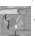
- the model 22 can then be re-projected onto the image, as is shown in FIG. 5 .
- the re-projection 52' of the model more closely matches corresponding features in the image 50, even though the image 50 still suffers from leaning.
- the image 50 can therefore still be used for future modeling tasks, such as updating the model 22, making corrections to it, adding to the model, etc.
- the system greatly improves the functionality of computerized modeling systems as it allows for usage of imperfect imagery (e.g., images suffering from leaning) during the process of computer modeling of structures.
Landscapes
- Engineering & Computer Science (AREA)
- Physics & Mathematics (AREA)
- Geometry (AREA)
- Theoretical Computer Science (AREA)
- General Physics & Mathematics (AREA)
- Software Systems (AREA)
- Computer Graphics (AREA)
- Computer Hardware Design (AREA)
- Architecture (AREA)
- General Engineering & Computer Science (AREA)
- Mathematical Optimization (AREA)
- Pure & Applied Mathematics (AREA)
- Evolutionary Computation (AREA)
- Mathematical Analysis (AREA)
- Computational Mathematics (AREA)
- Remote Sensing (AREA)
- Structural Engineering (AREA)
- Civil Engineering (AREA)
- Processing Or Creating Images (AREA)
- Image Processing (AREA)
Abstract
Description
- This application claims the benefit of
U.S. Provisional Patent Application No. 62/646,985 filed on March 23, 2018 - The present disclosure relates generally to the fields of computer vision and photogrammetry. More specifically, the present disclosure relates to systems and methods for lean ortho correction for computer models of structures
- In the fields of computer vision and photogrammetry, there is often a need to project three-dimensional computer models of structures onto images that are not perfect. For example, many digital images suffer from leaning which has not been corrected. In such circumstances, while the digital images may be identified as "orthorectified," the images are not true orthographic images due to the failure to correct leaning in the images. As a result, existing computer modeling systems can produce models of structures that are inaccurate, or which are not properly projected onto images. Accordingly, it would be desirable to provide systems and methods for lean ortho correction of computer models of structures which addresses the foregoing needs.
- This present disclosure relates to systems and methods for lean ortho correction for computer models of structures. The system includes a transformation module which adjusts projections of computer models onto images that suffer from leaning and/or distortions present in the images, so that the images are still useful in generating and/or refining existing computer models of structures. The system displays a projection of a computer model onto an orthorectified image that suffers from leaning, and the user determines two world three-dimensional (3D) points in the image such that the
second world 3D point has a height which is different than the height of thefirst world 3D point, and a third point where thesecond world 3D point is actually displayed in the image. The points can be identified by a user using a graphical user interface and an associated input device, or automatically using suitable computer vision techniques capable of identifying the points. Using the identified points, the system transforms the coordinates of the model points using a lean ortho correction algorithm, and re-projects the model onto the orthorectified image so that the projected model more accurately aligns with features of the orthorectified image. - The foregoing features of the invention will be apparent from the following Detailed Description, taken in connection with the accompanying drawings, in which:
-
FIG. 1 is a diagram illustrating the system of the present disclosure; -
FIG. 2 is a flowchart illustrating processing steps carried out by the system; -
FIG. 3 depicts identification of a set of points in an orthorectified image suffering from leaning; -
FIG. 4 depicts identification of an alternate set of points in the orthorectified image; and -
FIG. 5 depicts projection of transformed computer model onto the orthorectified image after processing of model coordinates using a lean ortho correction algorithm. - The present disclosure relates to systems and methods for lean ortho correction for computer models of structures, as discussed in detail below in connection with
FIGS. 1-5 . -
FIG. 1 is a diagram illustrating the system of the present disclosure, indicated generally at 10. Thesystem 10 includes atransformation module 12 that is executed by aprocessor 14 and which processes astructure model 22 stored in amemory 20 in communication with theprocessor 14, and auser interface 26 that communicates with theprocessor 14 and which can be operated by a user of thesystem 10. Thestructure model 22 could include a wireframe or polygonal model of a structure, such as a three-dimensional model of a house as shown. Importantly, thesystem 10 rapidly transforms coordinates of thestructure model 22 to better fit anorthorectified image 16 that suffers from leaning. As can be seen inFIG. 1 ., when aprojection 18 of themodel 22 is projected onto theimage 16, it can be seen that theprojection 18 does not adequately align with corresponding features in theimage 16 due to the presence of lean in theimage 16. After processing of themodel 22 using thetransformation module 12 and points identified in the image 16 (as will be discussed in greater detail below), coordinates of themodel 22 are transformed and the model is re-projected as projection 18' onto theimage 16 as seen inFIG. 1 . As can be appreciated, the transformed model and projection 18' more closely match corresponding features in theimage 16, despite the fact that the image still suffers from leaning. Advantageously, this allows a user to create/modify models of structures using digital imagery that ordinarily would not be useful for modeling due to the presence of lean in the image, thereby improving the functioning of computer modeling systems. - As will be discussed in greater detail below, points could be identified in the
image 16 by the user using theuser interface 26, or automatically through suitable computer vision techniques. Theuser interface 26 could include, but is not limited to, a display and associated keyboard and/or mouse, a touchscreen, lightpen, etc. Moreover, the process steps of the invention disclosed herein (carried out by the module 12) could be embodied as computer-readable software code executed by one or more computer systems, and could be programmed using any suitable programming languages including, but not limited to, C, C++, C#, Java, Python, or any other suitable languages. Additionally, the computer system(s) on which the present invention could be embodied include, but are not limited to, one or more personal computers, servers, mobile devices, cloud-based computing platforms, etc., each having one or more suitably powerful microprocessors and associated operating system(s) such as Linux, UNIX, Microsoft Windows, MacOS, etc. Still further, the invention could be embodied as a customized hardware component such as a field-programmable gate array (FPGA), application-specific integrated circuit (ASIC), embedded system, or other customized hardware component without departing from the spirit or scope of the present disclosure. - The specific functions carried out by the system 10 (and in particular, the transformation module 12) will now be discussed with reference to
FIG. 2 , which is aflowchart 30 illustrating processing steps carried out by the system of the present disclosure, and additionally with reference toFIGS. 3-5 . Instep 32, the system displays an orthorectified image, such as theimage 50 shown inFIG. 3 . Theimage 50 could be displayed on a screen of theuser interface 26 ofFIG. 1 , and suffers from leaning. Next, instep 34, the system projects aprojection 52 computer model of the structure (house) shown inFIG. 3 onto theimage 50. As can be seen inFIG. 3 , theprojection 52 is a wireframe representation of the model, but not all features of the projected model match corresponding features in theimage 50 due to the presence of lean in the image. Next, instep 36, the user identifies a first world three-dimensional (3D) point A shown in theimage 50. As can be seen inFIG. 3 , the point A corresponds to a roof corner appearing on one corner of the roof of the building shown in theimage 50. Next, instep 38, the user identifies a second world three-dimensional (3D) point B shown in theimage 50 having an elevation (height) which is greater than the elevation (height) of point A. As can be seen inFIG. 3 , point B corresponds to one end of a roof ridge of thewireframe projection 52. Next, instep 40, the user identifies a point C in theimage 50 where thesecond world point 3D point B actually appears in theimage 50. As can be seen, point C in theimage 50 shows the actual location of one end of the roof ridge that corresponds to the point B identified by the system. -
FIG. 4 shows an alternate set of points that could be identified and used by the system, in theimage 50. For example, as can be seen, point A is thefirst world 3D point corresponding to a different corner of the roof of the building shown inFIG. 4 , point B is thesecond world 3D point in the image having a height greater that the point A, and point C is a point identifying the actual location in theimage 50 corresponding to point B. It is noted that the points A, B, and C could be identified by a user pointing and clicking on the points in the image using a mouse and display of theuser interface 26 ofFIG. 1 , or automatically identified using computer vision techniques. For example, classical computer vision approaches can be used for point detection, as well as more sophisticated systems based on deep neural networks architectures to locate keypoints. - In
step 42, the system transforms the coordinates of the model using the points A, B, and C identified in theimage 50 and a lean ortho correction algorithm. Two suitable algorithms could be used - one algorithm which transforms the image coordinates to the model coordinates, or a second algorithm which transforms the model coordinates to the image coordinates. If the world coordinates of a corner of the image and the pixel size (ratio between world coordinates and pixel) in both X and Y direction are known, the system can use the following algorithms to convert from pixel to world coordinates, and vice versa:

- It is noted that the "WorldZ" in Algorithms 1 and 2 are not required to calculate pixel location. Point A in
FIGS. 3-4 (Ax, Ay, Az) is aworld 3D point that matches perfectly with the corresponding image pixel when applying Algorithms 1 and 2, and it is noted that the values of Ax and Ay are optional. Point B inFIGS. 3-4 (Bx, By, Bz) is aworld 3D point where the height of A (Az) is different from the height of B (Bz). In this case, the corresponding image pixel should not match B when applying Algorithms 1 and 2. Point C inFIGS. 3-4 (Cpx, Cpy) is the location where point B is actually displayed in the image. - Once these points have been identified, the following can be calculated: leanZ0 = Az; Bpx, Bpy = <transformation of point B from World coordinates to pixel coordinates using formula 1>; and leanVector = (Cp - Bp) / (Bz - Az). Then, Algorithms 3 and 4 can be applied to transform the model more accurately, as follows:


- Once the foregoing algorithms have been applied, the coordinates of the
model 22 ofFIG. 1 are transformed by the system. Themodel 22 can then be re-projected onto the image, as is shown inFIG. 5 . As can be seen inFIG. 5 , the re-projection 52' of the model more closely matches corresponding features in theimage 50, even though theimage 50 still suffers from leaning. Theimage 50 can therefore still be used for future modeling tasks, such as updating themodel 22, making corrections to it, adding to the model, etc. As can be appreciated, the system greatly improves the functionality of computerized modeling systems as it allows for usage of imperfect imagery (e.g., images suffering from leaning) during the process of computer modeling of structures. - Having thus described the system and method in detail, it is to be understood that the foregoing description is not intended to limit the spirit or scope thereof. It will be understood that the embodiments of the present disclosure described herein are merely exemplary and that a person skilled in the art may make any variations and modification without departing from the spirit and scope of the disclosure. All such variations and modifications, including those discussed above, are intended to be included within the scope of the disclosure. What is intended to be protected by Letters Patent is set forth in the following claims.
- Alternative statements of invention are recited below as numbered clauses.
- 1. A system for lean ortho correction for computer models of structures, comprising:
- a processor for processing a structure model stored in a non-transitory memory;
- a user interface in communication with the processor; and
- computer system code executed by the processor, the computer system code causing the processor to:
- display an image of a structure on the user interface;
- project the structure model onto the image;
- identify, via user input, a first world three-dimensional ("3D") point in the image;
- identify, via user input, a
second world 3D point in the image; - identify, via user input, a
third world 3D point in the image; and - transform coordinates of the structure model using the
first world 3D point, thesecond world 3D point, thethird world 3D point, and a lean ortho correction algorithm.
- 2. A method for lean ortho correction for computer models of structures, comprising steps of:
- displaying an image of a structure on a user interface of a computer system;
- projecting a structure model onto the image;
- identifying a first world three-dimensional ("3D") point in the image;
- identifying a
second world 3D point in the image; - identifying a
third world 3D point in the image; and - transforming coordinates of the structure model using the
first world 3D point, thesecond world 3D point, thethird world 3D point, and a lean ortho correction algorithm.
- 3. The system of clause 1, or the method of clause 2, wherein the structure model comprises a wireframe model or polygonal model of the structure.
- 4. The system or method of clause 3, wherein the structure is a three-dimensional model of a house or a building.
- 5. The system of clause 1 or any one of clauses 3 to 4, or the method of clause 2 or any one of clauses 3 to 4, wherein the
first world 3D point corresponds to a corner of the structure. - 6. The system or method of clause 5, wherein the
second world 3D point corresponds to a point on the structure model. - 7. The system or method of clause 6, wherein the
second world 3D point has an elevation greater than thefirst world 3D point. - 8. The system or method of clause 7, wherein the
third world 3D point corresponds to a point on the structure associated with thesecond world 3D point. - 9. The system or method of any preceding clause, wherein the lean ortho correction algorithm transforms image coordinates to model coordinates.
- 10. The system or method of any one of clauses 1 to 8, wherein the lean ortho correction algorithm transforms model coordinates to image coordinates.
- 11. The system of clause 1 or any one of clauses 3 to 10, wherein the processor re-projects the transformed coordinates of the structure model onto the image.
- 12. The method of clause 2 or any one of clauses 3 to 10, further comprising re-projecting the transformed coordinates of the structure model onto the image.
Claims (15)
- A method for lean ortho correction for computer models of structures, comprising steps of:projecting a structure model onto an image;identifying a plurality of world three-dimensional ("3D") points in the image; andadjusting the structure model by transforming coordinates of the structure model using the plurality of world 3D points and a lean ortho correction algorithm to compensate for lean in the image.
- The method of Claim 1 wherein the structure model comprises a wireframe model or polygonal model of the structure.
- The method of Claim 2, wherein the structure is a three-dimensional model of a house or a building.
- The method of any preceding claim, wherein the plurality of world three-dimensional ("3D") points in the image comprises a first world 3D point in the image, a second world 3D point in the image and a third world 3D point in the image.
- The method of claim 4, wherein the first world 3D point corresponds to a corner of the structure.
- The method of Claim 5, wherein the second world 3D point corresponds to a point on the structure model and optionally wherein the second world 3D point has an elevation greater than the first world 3D point.
- The method of Claim 6, wherein the third world 3D point corresponds to a point on the structure associated with the second world 3D point.
- The method of any preceding Claim, wherein the lean ortho correction algorithm transforms image coordinates to model coordinates.
- The method of any one of Claims 1 to 7, wherein the lean ortho correction algorithm transforms model coordinates to image coordinates.
- The method of any preceding Claim, further comprising re-projecting the transformed coordinates of the structure model onto the image.
- The method of any preceding claim, wherein the image is an orthorectified image.
- The method of any preceding claim, further comprising displaying an image of a structure on a user interface of a computer system.
- The method of any preceding claim, further comprising identifying the plurality of world 3D points via user input.
- The method of any preceding claim, wherein the lean ortho correction algorithm calculates at least one lean value and at least one lean vector for each of the plurality of world 3D points and applies the at least one lean value and the at least one lean vector to transform the coordinates of the structure model.
- A system for lean ortho correction for computer models of structures, comprising:a processor for processing a structure model;a user interface in communication with the processor; andcomputer system code executed by the processor, the computer system code causing the processor to perform the method of any preceding claim.
Applications Claiming Priority (2)
| Application Number | Priority Date | Filing Date | Title |
|---|---|---|---|
| US201862646985P | 2018-03-23 | 2018-03-23 | |
| EP19164723.9A EP3543878B1 (en) | 2018-03-23 | 2019-03-22 | Systems and methods for lean ortho correction for computer models of structures |
Related Parent Applications (2)
| Application Number | Title | Priority Date | Filing Date |
|---|---|---|---|
| EP19164723.9A Division-Into EP3543878B1 (en) | 2018-03-23 | 2019-03-22 | Systems and methods for lean ortho correction for computer models of structures |
| EP19164723.9A Division EP3543878B1 (en) | 2018-03-23 | 2019-03-22 | Systems and methods for lean ortho correction for computer models of structures |
Publications (2)
| Publication Number | Publication Date |
|---|---|
| EP4557230A2 true EP4557230A2 (en) | 2025-05-21 |
| EP4557230A3 EP4557230A3 (en) | 2025-07-30 |
Family
ID=65991523
Family Applications (2)
| Application Number | Title | Priority Date | Filing Date |
|---|---|---|---|
| EP19164723.9A Active EP3543878B1 (en) | 2018-03-23 | 2019-03-22 | Systems and methods for lean ortho correction for computer models of structures |
| EP25160745.3A Pending EP4557230A3 (en) | 2018-03-23 | 2019-03-22 | Systems and methods for lean ortho correction for computer models of structures |
Family Applications Before (1)
| Application Number | Title | Priority Date | Filing Date |
|---|---|---|---|
| EP19164723.9A Active EP3543878B1 (en) | 2018-03-23 | 2019-03-22 | Systems and methods for lean ortho correction for computer models of structures |
Country Status (4)
| Country | Link |
|---|---|
| US (3) | US11450076B2 (en) |
| EP (2) | EP3543878B1 (en) |
| AU (2) | AU2019201991A1 (en) |
| CA (1) | CA3037583A1 (en) |
Families Citing this family (7)
| Publication number | Priority date | Publication date | Assignee | Title |
|---|---|---|---|---|
| CA3037583A1 (en) | 2018-03-23 | 2019-09-23 | Geomni, Inc. | Systems and methods for lean ortho correction for computer models of structures |
| WO2022125787A1 (en) | 2020-12-09 | 2022-06-16 | Zesty.Ai, Inc. | Determining 3d structure features from dsm data |
| US11094135B1 (en) | 2021-03-05 | 2021-08-17 | Flyreel, Inc. | Automated measurement of interior spaces through guided modeling of dimensions |
| CA3212906A1 (en) * | 2021-04-08 | 2022-10-13 | Bryce Zachary Porter | Computer vision systems and methods for determining roof shapes from imagery using segmentation networks |
| US12360286B2 (en) | 2022-10-14 | 2025-07-15 | Zesty.Ai, Inc. | Hail predictions using artificial intelligence |
| US12360287B2 (en) | 2022-10-14 | 2025-07-15 | Zesty.Ai, Inc. | Hail frequency predictions using artificial intelligence |
| US12536594B2 (en) | 2022-10-14 | 2026-01-27 | Zesty.Ai, Inc. | Hail severity predictions using artificial intelligence |
Family Cites Families (6)
| Publication number | Priority date | Publication date | Assignee | Title |
|---|---|---|---|---|
| US8170840B2 (en) * | 2008-10-31 | 2012-05-01 | Eagle View Technologies, Inc. | Pitch determination systems and methods for aerial roof estimation |
| US9911228B2 (en) * | 2010-02-01 | 2018-03-06 | Eagle View Technologies, Inc. | Geometric correction of rough wireframe models derived from photographs |
| AU2011312140C1 (en) * | 2010-10-07 | 2016-02-18 | Sungevity | Rapid 3D modeling |
| AU2013326865B2 (en) * | 2012-10-05 | 2019-03-21 | Eagle View Technologies, Inc. | Determining image transforms without using image acquisition metadata |
| US10032310B2 (en) * | 2016-08-22 | 2018-07-24 | Pointivo, Inc. | Methods and systems for wireframes of a structure or element of interest and wireframes generated therefrom |
| CA3037583A1 (en) | 2018-03-23 | 2019-09-23 | Geomni, Inc. | Systems and methods for lean ortho correction for computer models of structures |
-
2019
- 2019-03-21 CA CA3037583A patent/CA3037583A1/en active Pending
- 2019-03-22 AU AU2019201991A patent/AU2019201991A1/en not_active Abandoned
- 2019-03-22 EP EP19164723.9A patent/EP3543878B1/en active Active
- 2019-03-22 US US16/361,620 patent/US11450076B2/en active Active
- 2019-03-22 EP EP25160745.3A patent/EP4557230A3/en active Pending
-
2022
- 2022-09-20 US US17/948,659 patent/US11847757B2/en active Active
-
2023
- 2023-12-18 US US18/543,502 patent/US20240119691A1/en active Pending
-
2024
- 2024-07-24 AU AU2024205074A patent/AU2024205074A1/en active Pending
Also Published As
| Publication number | Publication date |
|---|---|
| CA3037583A1 (en) | 2019-09-23 |
| EP3543878A1 (en) | 2019-09-25 |
| EP3543878B1 (en) | 2025-05-07 |
| US11847757B2 (en) | 2023-12-19 |
| US20190295328A1 (en) | 2019-09-26 |
| US11450076B2 (en) | 2022-09-20 |
| US20230017465A1 (en) | 2023-01-19 |
| AU2024205074A1 (en) | 2024-08-15 |
| EP4557230A3 (en) | 2025-07-30 |
| US20240119691A1 (en) | 2024-04-11 |
| AU2019201991A1 (en) | 2019-10-10 |
Similar Documents
| Publication | Publication Date | Title |
|---|---|---|
| EP4557230A2 (en) | Systems and methods for lean ortho correction for computer models of structures | |
| US12340575B2 (en) | Vehicle detecting system, vehicle detecting method, and program storage medium | |
| US11417077B2 (en) | Systems and methods for rapid alignment of digital imagery datasets to models of structures | |
| JP6208094B2 (en) | Information processing apparatus, information processing system, information processing method, and program thereof | |
| AU2016208411B2 (en) | Identifying shapes in an image by comparing bézier curves | |
| US11922659B2 (en) | Coordinate calculation apparatus, coordinate calculation method, and computer-readable recording medium | |
| EP3096489B1 (en) | Remote control method and apparatus | |
| CN112529928A (en) | Part assembly detection method, computer device and storage medium | |
| US20250191554A1 (en) | System and method for causing graphical information to be rendered | |
| CN113269728B (en) | Visual edge-tracking method, device, readable storage medium and program product | |
| US10866633B2 (en) | Signing with your eyes | |
| US9965676B2 (en) | Method and system for identifying a plurality of reference points in a hand drawing track | |
| US20250209659A1 (en) | Input assistance apparatus, input assistance method, and non-transitory computer readable medium | |
| CN111062874B (en) | Text image display method, device, equipment and storage medium | |
| CA3089200C (en) | Systems and methods for rapid alignment of digital imagery datasets to models of structures | |
| US20240338845A1 (en) | Image processing apparatus, feature map generating apparatus, learning model generation apparatus, image processing method, and computer-readable recording medium | |
| US20240037783A1 (en) | Information processing system, information processing apparatus, information processing method, and recording medium | |
| JPWO2019049317A1 (en) | Ranging device and ranging method | |
| JP2009015729A (en) | Reference model creation method and reference model creation device | |
| CN121074321A (en) | System and method for establishing augmented reality and positioning and guiding method for augmented reality | |
| CN119273766A (en) | House calibration method, device and extended reality device | |
| JPH05173750A (en) | Graphic processor |
Legal Events
| Date | Code | Title | Description |
|---|---|---|---|
| PUAI | Public reference made under article 153(3) epc to a published international application that has entered the european phase |
Free format text: ORIGINAL CODE: 0009012 |
|
| STAA | Information on the status of an ep patent application or granted ep patent |
Free format text: STATUS: THE APPLICATION HAS BEEN PUBLISHED |
|
| AC | Divisional application: reference to earlier application |
Ref document number: 3543878 Country of ref document: EP Kind code of ref document: P |
|
| AK | Designated contracting states |
Kind code of ref document: A2 Designated state(s): AL AT BE BG CH CY CZ DE DK EE ES FI FR GB GR HR HU IE IS IT LI LT LU LV MC MK MT NL NO PL PT RO RS SE SI SK SM TR |
|
| REG | Reference to a national code |
Ref country code: DE Ref legal event code: R079 Free format text: PREVIOUS MAIN CLASS: G06T0019200000 Ipc: G06T0017050000 |
|
| PUAL | Search report despatched |
Free format text: ORIGINAL CODE: 0009013 |
|
| AK | Designated contracting states |
Kind code of ref document: A3 Designated state(s): AL AT BE BG CH CY CZ DE DK EE ES FI FR GB GR HR HU IE IS IT LI LT LU LV MC MK MT NL NO PL PT RO RS SE SI SK SM TR |
|
| RIC1 | Information provided on ipc code assigned before grant |
Ipc: G06T 17/05 20110101AFI20250625BHEP Ipc: G06F 30/13 20200101ALI20250625BHEP Ipc: G06T 17/20 20060101ALI20250625BHEP Ipc: G06T 13/20 20110101ALI20250625BHEP Ipc: G06T 19/20 20110101ALI20250625BHEP |
|
| STAA | Information on the status of an ep patent application or granted ep patent |
Free format text: STATUS: REQUEST FOR EXAMINATION WAS MADE |
|
| 17P | Request for examination filed |
Effective date: 20260130 |