EP4557046A1 - Electronic device - Google Patents
Electronic device Download PDFInfo
- Publication number
- EP4557046A1 EP4557046A1 EP24190313.7A EP24190313A EP4557046A1 EP 4557046 A1 EP4557046 A1 EP 4557046A1 EP 24190313 A EP24190313 A EP 24190313A EP 4557046 A1 EP4557046 A1 EP 4557046A1
- Authority
- EP
- European Patent Office
- Prior art keywords
- support plate
- metal support
- electronic device
- housing body
- dimensional antenna
- Prior art date
- Legal status (The legal status is an assumption and is not a legal conclusion. Google has not performed a legal analysis and makes no representation as to the accuracy of the status listed.)
- Pending
Links
Images


Classifications
-
- G—PHYSICS
- G06—COMPUTING OR CALCULATING; COUNTING
- G06F—ELECTRIC DIGITAL DATA PROCESSING
- G06F1/00—Details not covered by groups G06F3/00 - G06F13/00 and G06F21/00
- G06F1/16—Constructional details or arrangements
- G06F1/1613—Constructional details or arrangements for portable computers
- G06F1/1633—Constructional details or arrangements of portable computers not specific to the type of enclosures covered by groups G06F1/1615 - G06F1/1626
- G06F1/1684—Constructional details or arrangements related to integrated I/O peripherals not covered by groups G06F1/1635 - G06F1/1675
- G06F1/1698—Constructional details or arrangements related to integrated I/O peripherals not covered by groups G06F1/1635 - G06F1/1675 the I/O peripheral being a sending/receiving arrangement to establish a cordless communication link, e.g. radio or infrared link, integrated cellular phone
-
- H—ELECTRICITY
- H01—ELECTRIC ELEMENTS
- H01Q—ANTENNAS, i.e. RADIO AERIALS
- H01Q1/00—Details of, or arrangements associated with, antennas
- H01Q1/12—Supports; Mounting means
- H01Q1/22—Supports; Mounting means by structural association with other equipment or articles
- H01Q1/24—Supports; Mounting means by structural association with other equipment or articles with receiving set
- H01Q1/241—Supports; Mounting means by structural association with other equipment or articles with receiving set used in mobile communications, e.g. GSM
- H01Q1/242—Supports; Mounting means by structural association with other equipment or articles with receiving set used in mobile communications, e.g. GSM specially adapted for hand-held use
- H01Q1/243—Supports; Mounting means by structural association with other equipment or articles with receiving set used in mobile communications, e.g. GSM specially adapted for hand-held use with built-in antennas
-
- H—ELECTRICITY
- H01—ELECTRIC ELEMENTS
- H01Q—ANTENNAS, i.e. RADIO AERIALS
- H01Q1/00—Details of, or arrangements associated with, antennas
- H01Q1/12—Supports; Mounting means
- H01Q1/22—Supports; Mounting means by structural association with other equipment or articles
-
- G—PHYSICS
- G06—COMPUTING OR CALCULATING; COUNTING
- G06F—ELECTRIC DIGITAL DATA PROCESSING
- G06F1/00—Details not covered by groups G06F3/00 - G06F13/00 and G06F21/00
- G06F1/16—Constructional details or arrangements
- G06F1/1613—Constructional details or arrangements for portable computers
- G06F1/1633—Constructional details or arrangements of portable computers not specific to the type of enclosures covered by groups G06F1/1615 - G06F1/1626
- G06F1/1662—Details related to the integrated keyboard
- G06F1/1671—Special purpose buttons or auxiliary keyboards, e.g. retractable mini keypads, keypads or buttons that remain accessible at closed laptop
-
- H—ELECTRICITY
- H01—ELECTRIC ELEMENTS
- H01Q—ANTENNAS, i.e. RADIO AERIALS
- H01Q1/00—Details of, or arrangements associated with, antennas
- H01Q1/36—Structural form of radiating elements, e.g. cone, spiral, umbrella; Particular materials used therewith
-
- H—ELECTRICITY
- H01—ELECTRIC ELEMENTS
- H01Q—ANTENNAS, i.e. RADIO AERIALS
- H01Q1/00—Details of, or arrangements associated with, antennas
- H01Q1/36—Structural form of radiating elements, e.g. cone, spiral, umbrella; Particular materials used therewith
- H01Q1/38—Structural form of radiating elements, e.g. cone, spiral, umbrella; Particular materials used therewith formed by a conductive layer on an insulating support
-
- H—ELECTRICITY
- H01—ELECTRIC ELEMENTS
- H01Q—ANTENNAS, i.e. RADIO AERIALS
- H01Q21/00—Antenna arrays or systems
-
- H—ELECTRICITY
- H01—ELECTRIC ELEMENTS
- H01Q—ANTENNAS, i.e. RADIO AERIALS
- H01Q21/00—Antenna arrays or systems
- H01Q21/28—Combinations of substantially independent non-interacting antenna units or systems
-
- H—ELECTRICITY
- H01—ELECTRIC ELEMENTS
- H01Q—ANTENNAS, i.e. RADIO AERIALS
- H01Q5/00—Arrangements for simultaneous operation of antennas on two or more different wavebands, e.g. dual-band or multi-band arrangements
- H01Q5/20—Arrangements for simultaneous operation of antennas on two or more different wavebands, e.g. dual-band or multi-band arrangements characterised by the operating wavebands
Definitions
- the present invention relates to an electronic device, and more particularly to a multi-antenna electronic device.
- Peripheral mechanism spaces of tablet PC type electronic devices are too small and can hardly meet the design manner of multi-antenna communication systems in consideration with the requirements for cost reduction/detachable antennae, etc. Therefore, how to add new antennae in the limited peripheral mechanism spaces is an important issue to be solved in this technical field.
- the present invention provides an electronic device, which can break through the space limitation, form a metal cavity and resonate to generate a target antenna frequency band and an available radiation pattern by means of a space between side buttons and a housing through a special design, and meet the design of a multi-antenna communication system at the same time.
- the electronic device comprises a housing, a metal support plate, a three-dimensional antenna bracket and a side button circuit board, where the housing comprises an upper housing body and a lower housing body; the metal support plate is arranged in the housing; the three-dimensional antenna bracket is arranged in a first space between the metal support plate and the lower housing body; the side button circuit board is arranged in a second space between the metal support plate and the upper housing body; and the area of the three-dimensional antenna bracket and the area of the side button circuit board on the metal support plate partially overlap with each other.
- the electronic device comprises a housing, a metal support plate, a three-dimensional antenna bracket and a side button circuit board, where the housing comprises an upper housing body and a lower housing body; the metal support plate is arranged in the housing; the three-dimensional antenna bracket is arranged in a first space between the metal support plate and the lower housing body; the side button circuit board is arranged in a second space between the metal support plate and the upper housing body; and the area of the three-dimensional antenna bracket and the area of the side button circuit board on the metal support plate completely overlap with each other.
- the upper housing body comprises a display frame, and the display frame is configured to fixedly arrange a display panel.
- the upper housing body comprises a side button frame, and the side button frame is configured to fixedly arrange the side button circuit board.
- the metal support plate relative to a plane of the metal support plate, comprises a protruding portion in the second space, and the protruding portion is configured to abut against the side button circuit board.
- the metal support plate relative to a plane of the metal support plate, comprises a concave portion and a metal wall in the first space, and the concave portion and the metal wall are configured to fixedly arrange the three-dimensional antenna bracket.
- the three-dimensional antenna bracket comprises at least one hollow portion facing the metal support plate.
- the metal support plate comprises at least one opening facing the three-dimensional antenna bracket, and the at least one opening corresponds to the at least one hollow portion.
- the three-dimensional antenna bracket comprises a soft-board antenna facing the lower housing body.
- the electronic device by means of the spaces between side buttons and the housing, the three-dimensional antenna bracket and the metal support plate form a radiation cavity to resonate to generate a target antenna frequency band and an available radiation pattern, and meanwhile, the electronic device can meet the multi-antenna design requirement.
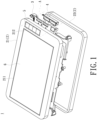
- FIGS. 1-4 are an exploded schematic diagram of an electronic device provided in an embodiment of the present invention, a front perspective view of an electronic device provided in an embodiment of the present invention, a side schematic diagram of side buttons of an electronic device provided in an embodiment of the present invention, and a back perspective view of an electronic device provided in an embodiment of the present invention, respectively.
- the electronic device 1 provided in this embodiment includes a housing 2, a metal support plate 3, a three-dimensional antenna bracket 4 (located at the position of an antenna 6), and a side button circuit board 5.
- the electronic device 1 is a tablet PC, and more particularly a reinforced tablet PC.
- the housing 2 of the electronic device 1 includes an upper housing body 21 and a lower housing body 22, where the upper housing body 21 includes a display frame 211 and a side button frame 212, the display frame 211 is configured to fixedly arrange a (touchable) display panel 6, and the side button frame 212 is configured to fixedly arrange the side button circuit board 5.
- the upper housing body 21 and the lower housing body 22 of the housing 2 are only intended to explain an upper/top portion and a lower/bottom portion of the housing 2, not to define the structure and combination of the housing 2, for example, the housing can be integrally formed.
- the metal support plate 3 is arranged in the housing 2 and is configured to reinforce the structure of the electronic device 1, and a system circuit board (not shown) can be arranged at the front or back of the metal support plate 3 and be connected to the display panel 6 by means of a transmission flat cable. Besides, edges of the metal support plate 3 can be cut and punched according to the shapes of peripheral mechanisms such as modules, devices, circuits, for example, antenna modules, camera modules, scanning modules, etc., due to the arrangement of these mechanisms. It should be particularly noted that the present invention focuses on the (overlapping) relationship of the side button circuit board 5, the metal support plate 3 and the three-dimensional antenna bracket 4.
- FIGS. 5 and 6 are a top schematic diagram and a bottom schematic diagram of an area A in FIG. 1 , respectively.
- the side button circuit board 5 is arranged in a space 11 between the metal support plate 3 and the upper housing body 21, where the metal support plate 3, relative to a plane of the metal support plate 3, includes a protruding portion 31 in the space 11, and the protruding portion 31 is configured to abut against the side button circuit board 5, so as to ensure that the side button circuit board 5 is fixedly arranged in the side button frame 212.
- FIG. 5 the side button circuit board 5 is arranged in a space 11 between the metal support plate 3 and the upper housing body 21, where the metal support plate 3, relative to a plane of the metal support plate 3, includes a protruding portion 31 in the space 11, and the protruding portion 31 is configured to abut against the side button circuit board 5, so as to ensure that the side button circuit board 5 is fixedly arranged in the side button frame 212.
- the three-dimensional antenna bracket 4 is arranged in a space 12 between the metal support plate 3 and the lower housing body 22, where the metal support plate 3, relative to a plane of the metal support plate 3, includes a concave portion 33 and a metal wall 32 in the space 12, and the metal wall 32 and the concave portion 33 are configured to fixedly arrange the three-dimensional antenna bracket 4, so as to ensure that the three-dimensional antenna bracket 4 is fixedly arranged in the space 12.
- the protruding shape and the concave shape of the protruding portion 31 and the concave portion 33 represent the relative relationship instead of defining a protrusion or a recess.
- the three-dimensional antenna bracket 4 and the side button circuit board 5 are correspondingly arranged across the metal support plate 3, and the area of the three-dimensional antenna bracket 4 and the area of the side button circuit board 5 on the metal support plate 3 completely overlap with each other. Moreover, in other embodiments, the area of the three-dimensional antenna bracket 4 and the area of the side button circuit board 5 on the metal support plate 3 can partially overlap with each other.
- the metal support plate 3 can include at least one opening 34 facing the three-dimensional antenna bracket 4 or include no opening 34; in this embodiment, the metal support plate 3 includes two openings 34 for preventing electronic components at the back of the side button circuit board 5 from making contact with the metal support plate 3 due to their heights; and in other embodiments, the metal support plate 3 can include a plurality of openings 34.
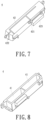
- FIGS. 7 and 8 are a top schematic diagram and a bottom schematic diagram of the three-dimensional antenna bracket provided in an embodiment of the present invention, respectively.
- the surface of the three-dimensional antenna bracket 4 provided in this embodiment facing the lower housing body 22 and the metal wall 32 is configured to provide a soft-board antenna 42, where the soft-board antenna 42 includes a feed-in point 421 and grounding points 422, 423, and the shape of the soft-board antenna 42 in this figure is only for illustration. A person skilled in the antenna field can design the shape of the antenna according to actual needs, and the present invention is not limited to this.
- FIG. 7 the surface of the three-dimensional antenna bracket 4 provided in this embodiment facing the lower housing body 22 and the metal wall 32 is configured to provide a soft-board antenna 42, where the soft-board antenna 42 includes a feed-in point 421 and grounding points 422, 423, and the shape of the soft-board antenna 42 in this figure is only for illustration. A person skilled in the antenna field can design the shape of the antenna according to actual needs, and the present
- the surface of the three-dimensional antenna bracket 4 provided in this embodiment facing the metal support plate 3 includes at least one hollow portion 41 to form a radiation cavity, for example, the three-dimensional antenna bracket 4 includes two hollow portions 41 which can correspond to the two openings 34 of the metal support plate 3 or do not correspond to the two openings 34 of the metal support plate 3; in other embodiments, the three-dimensional antenna bracket 4 can include no hollow portion 41 or include a plurality of hollow portions 41; and in other embodiments, the hollow portions 41 of the three-dimensional antenna bracket 4 and the openings 34 of the metal support plate 3 can be identical or different in number, thereby corresponding or not corresponding to each other.
- the electronic device by means of the spaces between side buttons and the housing, the three-dimensional antenna bracket and the metal support plate form the radiation cavity to resonate to generate a target antenna frequency band and an available radiation pattern, and meanwhile, the electronic device can meet the multi-antenna design requirement.
Landscapes
- Engineering & Computer Science (AREA)
- Computer Hardware Design (AREA)
- Theoretical Computer Science (AREA)
- General Engineering & Computer Science (AREA)
- Human Computer Interaction (AREA)
- Physics & Mathematics (AREA)
- General Physics & Mathematics (AREA)
- Computer Networks & Wireless Communication (AREA)
- Support Of Aerials (AREA)
Abstract
An electronic device includes a housing, a metal support plate, a three-dimensional antenna bracket and a side button circuit board. The housing includes an upper housing body and a lower housing body. The metal support plate is arranged in the housing. The three-dimensional antenna bracket is arranged in a first space between the metal support plate and the lower housing body. The side button circuit board is arranged in a second space between the metal support plate and the upper housing body. The area of the three-dimensional antenna bracket and the area of the side button circuit board on the metal support plate overlap with each other. Thus, the electronic device can meet the design requirement for a plurality of antennae, and the three-dimensional antenna bracket and the metal support plate form a radiation cavity to resonate to generate a target antenna frequency band and an available radiation pattern.
Description
- The instant application claims priority to
Chinese Patent Application 202311548679.3, filed November 20, 2023 - The present invention relates to an electronic device, and more particularly to a multi-antenna electronic device.
- Peripheral mechanism spaces of tablet PC type electronic devices are too small and can hardly meet the design manner of multi-antenna communication systems in consideration with the requirements for cost reduction/detachable antennae, etc. Therefore, how to add new antennae in the limited peripheral mechanism spaces is an important issue to be solved in this technical field.
- The present invention provides an electronic device, which can break through the space limitation, form a metal cavity and resonate to generate a target antenna frequency band and an available radiation pattern by means of a space between side buttons and a housing through a special design, and meet the design of a multi-antenna communication system at the same time.
- The electronic device provided in the present invention comprises a housing, a metal support plate, a three-dimensional antenna bracket and a side button circuit board, where the housing comprises an upper housing body and a lower housing body; the metal support plate is arranged in the housing; the three-dimensional antenna bracket is arranged in a first space between the metal support plate and the lower housing body; the side button circuit board is arranged in a second space between the metal support plate and the upper housing body; and the area of the three-dimensional antenna bracket and the area of the side button circuit board on the metal support plate partially overlap with each other.
- The electronic device provided in the present invention comprises a housing, a metal support plate, a three-dimensional antenna bracket and a side button circuit board, where the housing comprises an upper housing body and a lower housing body; the metal support plate is arranged in the housing; the three-dimensional antenna bracket is arranged in a first space between the metal support plate and the lower housing body; the side button circuit board is arranged in a second space between the metal support plate and the upper housing body; and the area of the three-dimensional antenna bracket and the area of the side button circuit board on the metal support plate completely overlap with each other.
- In an embodiment of the present invention, the upper housing body comprises a display frame, and the display frame is configured to fixedly arrange a display panel.
- In an embodiment of the present invention, the upper housing body comprises a side button frame, and the side button frame is configured to fixedly arrange the side button circuit board.
- In an embodiment of the present invention, the metal support plate, relative to a plane of the metal support plate, comprises a protruding portion in the second space, and the protruding portion is configured to abut against the side button circuit board.
- In an embodiment of the present invention, the metal support plate, relative to a plane of the metal support plate, comprises a concave portion and a metal wall in the first space, and the concave portion and the metal wall are configured to fixedly arrange the three-dimensional antenna bracket.
- In an embodiment of the present invention, the three-dimensional antenna bracket comprises at least one hollow portion facing the metal support plate.
- In an embodiment of the present invention, the metal support plate comprises at least one opening facing the three-dimensional antenna bracket, and the at least one opening corresponds to the at least one hollow portion.
- In an embodiment of the present invention, the three-dimensional antenna bracket comprises a soft-board antenna facing the lower housing body.
- With regard to the electronic device, by means of the spaces between side buttons and the housing, the three-dimensional antenna bracket and the metal support plate form a radiation cavity to resonate to generate a target antenna frequency band and an available radiation pattern, and meanwhile, the electronic device can meet the multi-antenna design requirement.
- Other objectives, features and advantages of the invention will be further understood from the further technological features disclosed by the embodiments of the invention wherein there are shown and described preferred embodiments of this invention, simply by way of illustration of modes best suited to carry out the invention.
-
-
FIG. 1 is an exploded schematic diagram of an electronic device provided in an embodiment of the present invention. -
FIG. 2 is a front perspective view of an electronic device provided in an embodiment of the present invention. -
FIG. 3 is a side schematic diagram of side buttons of an electronic device provided in an embodiment of the present invention. -
FIG. 4 is a back perspective view of an electronic device provided in an embodiment of the present invention. -
FIG. 5 is a top schematic diagram of an area A inFIG. 1 . -
FIG. 6 is a bottom schematic diagram of the area A inFIG. 1 . -
FIG. 7 is a top schematic diagram of a three-dimensional antenna bracket provided in an embodiment of the present invention. -
FIG. 8 is a bottom schematic diagram of a three-dimensional antenna bracket provided in an embodiment of the present invention. - In order to make the purposes, technical solutions and advantages of the present invention more clear, the present invention is further described in detail in conjunction with accompanying drawings and embodiments below. It should be understood that the specific embodiments described herein are only used to explain the present invention, not to define the present invention. On the basis of the embodiments of the present invention, all other embodiments obtained by those of ordinary skill in the pertinent technical field without involving any inventive effort should fall within the scope of protection of the present invention.
- Reference is made to
FIGS. 1-4 , which are an exploded schematic diagram of an electronic device provided in an embodiment of the present invention, a front perspective view of an electronic device provided in an embodiment of the present invention, a side schematic diagram of side buttons of an electronic device provided in an embodiment of the present invention, and a back perspective view of an electronic device provided in an embodiment of the present invention, respectively. Theelectronic device 1 provided in this embodiment includes ahousing 2, ametal support plate 3, a three-dimensional antenna bracket 4 (located at the position of an antenna 6), and a sidebutton circuit board 5. Theelectronic device 1 is a tablet PC, and more particularly a reinforced tablet PC. Thehousing 2 of theelectronic device 1 includes anupper housing body 21 and alower housing body 22, where theupper housing body 21 includes adisplay frame 211 and aside button frame 212, thedisplay frame 211 is configured to fixedly arrange a (touchable)display panel 6, and theside button frame 212 is configured to fixedly arrange the sidebutton circuit board 5. In addition, theupper housing body 21 and thelower housing body 22 of thehousing 2 are only intended to explain an upper/top portion and a lower/bottom portion of thehousing 2, not to define the structure and combination of thehousing 2, for example, the housing can be integrally formed. Themetal support plate 3 is arranged in thehousing 2 and is configured to reinforce the structure of theelectronic device 1, and a system circuit board (not shown) can be arranged at the front or back of themetal support plate 3 and be connected to thedisplay panel 6 by means of a transmission flat cable. Besides, edges of themetal support plate 3 can be cut and punched according to the shapes of peripheral mechanisms such as modules, devices, circuits, for example, antenna modules, camera modules, scanning modules, etc., due to the arrangement of these mechanisms. It should be particularly noted that the present invention focuses on the (overlapping) relationship of the sidebutton circuit board 5, themetal support plate 3 and the three-dimensional antenna bracket 4. - Reference is made to
FIGS. 5 and6 , which are a top schematic diagram and a bottom schematic diagram of an area A inFIG. 1 , respectively. InFIG. 5 , the sidebutton circuit board 5 is arranged in aspace 11 between themetal support plate 3 and theupper housing body 21, where themetal support plate 3, relative to a plane of themetal support plate 3, includes a protrudingportion 31 in thespace 11, and the protrudingportion 31 is configured to abut against the sidebutton circuit board 5, so as to ensure that the sidebutton circuit board 5 is fixedly arranged in theside button frame 212. InFIG. 6 , the three-dimensional antenna bracket 4 is arranged in aspace 12 between themetal support plate 3 and thelower housing body 22, where themetal support plate 3, relative to a plane of themetal support plate 3, includes aconcave portion 33 and ametal wall 32 in thespace 12, and themetal wall 32 and theconcave portion 33 are configured to fixedly arrange the three-dimensional antenna bracket 4, so as to ensure that the three-dimensional antenna bracket 4 is fixedly arranged in thespace 12. It should be noted that the protruding shape and the concave shape of the protrudingportion 31 and theconcave portion 33 represent the relative relationship instead of defining a protrusion or a recess. Besides, it should be particularly noted that, in this embodiment, the three-dimensional antenna bracket 4 and the sidebutton circuit board 5 are correspondingly arranged across themetal support plate 3, and the area of the three-dimensional antenna bracket 4 and the area of the sidebutton circuit board 5 on themetal support plate 3 completely overlap with each other. Moreover, in other embodiments, the area of the three-dimensional antenna bracket 4 and the area of the sidebutton circuit board 5 on themetal support plate 3 can partially overlap with each other. In addition, themetal support plate 3 can include at least one opening 34 facing the three-dimensional antenna bracket 4 or include noopening 34; in this embodiment, themetal support plate 3 includes twoopenings 34 for preventing electronic components at the back of the sidebutton circuit board 5 from making contact with themetal support plate 3 due to their heights; and in other embodiments, themetal support plate 3 can include a plurality ofopenings 34. - Reference is made to
FIGS. 7 and 8 , which are a top schematic diagram and a bottom schematic diagram of the three-dimensional antenna bracket provided in an embodiment of the present invention, respectively. InFIG. 7 , the surface of the three-dimensional antenna bracket 4 provided in this embodiment facing thelower housing body 22 and themetal wall 32 is configured to provide a soft-board antenna 42, where the soft-board antenna 42 includes a feed-inpoint 421 andgrounding points board antenna 42 in this figure is only for illustration. A person skilled in the antenna field can design the shape of the antenna according to actual needs, and the present invention is not limited to this. InFIG. 8 , the surface of the three-dimensional antenna bracket 4 provided in this embodiment facing themetal support plate 3 includes at least onehollow portion 41 to form a radiation cavity, for example, the three-dimensional antenna bracket 4 includes twohollow portions 41 which can correspond to the twoopenings 34 of themetal support plate 3 or do not correspond to the twoopenings 34 of themetal support plate 3; in other embodiments, the three-dimensional antenna bracket 4 can include nohollow portion 41 or include a plurality ofhollow portions 41; and in other embodiments, thehollow portions 41 of the three-dimensional antenna bracket 4 and theopenings 34 of themetal support plate 3 can be identical or different in number, thereby corresponding or not corresponding to each other. - In conclusion, with regard to the electronic device provided in the present invention, by means of the spaces between side buttons and the housing, the three-dimensional antenna bracket and the metal support plate form the radiation cavity to resonate to generate a target antenna frequency band and an available radiation pattern, and meanwhile, the electronic device can meet the multi-antenna design requirement.
- While the invention has been described in terms of what is presently considered to be the most practical and preferred embodiments, it is to be understood that the invention needs not be limited to the disclosed embodiment. On the contrary, it is intended to cover various modifications and similar arrangements included within the spirit and scope of the appended claims which are to be accorded with the broadest interpretation so as to encompass all such modifications and similar structures.
Claims (14)
- An electronic device (1), comprising:a housing (2), comprising an upper housing body (21) and a lower housing body (22);a metal support plate (3), arranged in the housing (2);a three-dimensional antenna bracket (4), arranged in a first space (12) between the metal support plate (3) and the lower housing body (22); anda side button circuit board (5), arranged in a second space (11) between the metal support plate (3) and the upper housing body (21),wherein an area of the three-dimensional antenna bracket (4) and an area of the side button circuit board (5) on the metal support plate (3) partially overlap with each other.
- The electronic device according to claim 1, wherein the upper housing body (21) comprises a display frame (211) and a side button frame (212), the display frame (211) is configured to fixedly arrange a display panel (6), and the side button frame (212) is configured to fixedly arrange the side button circuit board (5).
- The electronic device according to claim 1 or 2, wherein the metal support plate (3), relative to a plane of the metal support plate (3), comprises a protruding portion (31) in the second space (11), and the protruding portion (31) is configured to abut against the side button circuit board (5).
- The electronic device according to one of claims 1 to 3, wherein the metal support plate (3), relative to a plane of the metal support plate (3), comprises a concave portion (33) and a metal wall (32) in the first space (12), and the concave portion (33) and the metal wall (32) are configured to fixedly arrange the three-dimensional antenna bracket (4).
- The electronic device according to one of claims 1 to 4, wherein the three-dimensional antenna bracket (4) comprises at least one hollow portion (41) facing the metal support plate (3).
- The electronic device according to claim 5, wherein the metal support plate (3) comprises at least one opening (34) facing the three-dimensional antenna bracket (4), and the at least one opening (34) corresponds to the at least one hollow portion (41).
- The electronic device according to one of claims 1 to 6, wherein the three-dimensional antenna bracket (4) comprises a soft-board antenna (42) facing the lower housing body (22).
- An electronic device (1), comprising:a housing (2), comprising an upper housing body (21) and a lower housing body (22);a metal support plate (3), arranged in the housing (2);a three-dimensional antenna bracket (4), arranged in a first space (12) between the metal support plate (3) and the lower housing body (22); anda side button circuit board (5), arranged in a second space (11) between the metal support plate (3) and the upper housing body (21),wherein an area of the three-dimensional antenna bracket (4) and an area of the side button circuit board (5) on the metal support plate (3) completely overlap with each other.
- The electronic device according to claim 8, wherein the upper housing body (21) comprises a display frame (211) and a side button frame (212), the display frame (211) is configured to fixedly arrange a display panel (6), and the side button frame (212) is configured to fixedly arrange the side button circuit board (5).
- The electronic device according to claim 8 or 9, wherein the metal support plate (3), relative to a plane of the metal support plate (3), comprises a protruding portion (31) in the second space (11), and the protruding portion (31) is configured to abut against the side button circuit board (5).
- The electronic device according to one of claims 8 to 10, wherein the metal support plate (3), relative to a plane of the metal support plate (3), comprises a concave portion (33) and a metal wall (32) in the first space (12), and the concave portion (33) and the metal wall (32) are configured to fixedly arrange the three-dimensional antenna bracket (4).
- The electronic device according to one of claims 8 to 11, wherein the three-dimensional antenna bracket (4) comprises at least one hollow portion (41) facing the metal support plate (3).
- The electronic device according to claim 12, wherein the metal support plate (3) comprises at least one opening (34) facing the three-dimensional antenna bracket (4), and the at least one opening (34) corresponds to the at least one hollow portion (41).
- The electronic device according to one of claims 8 to 13, wherein the three-dimensional antenna bracket (4) comprises a soft-board antenna (42) facing the lower housing body (22).
Applications Claiming Priority (1)
| Application Number | Priority Date | Filing Date | Title |
|---|---|---|---|
| CN202311548679.3A CN120021094A (en) | 2023-11-20 | 2023-11-20 | Electronic Devices |
Publications (1)
| Publication Number | Publication Date |
|---|---|
| EP4557046A1 true EP4557046A1 (en) | 2025-05-21 |
Family
ID=91966065
Family Applications (1)
| Application Number | Title | Priority Date | Filing Date |
|---|---|---|---|
| EP24190313.7A Pending EP4557046A1 (en) | 2023-11-20 | 2024-07-23 | Electronic device |
Country Status (3)
| Country | Link |
|---|---|
| US (1) | US20250167430A1 (en) |
| EP (1) | EP4557046A1 (en) |
| CN (1) | CN120021094A (en) |
Citations (3)
| Publication number | Priority date | Publication date | Assignee | Title |
|---|---|---|---|---|
| US9871330B2 (en) * | 2014-09-22 | 2018-01-16 | Samsung Electronics Co., Ltd. | Waterproof key apparatus |
| CN208521220U (en) * | 2018-08-10 | 2019-02-19 | 深圳市销邦科技股份有限公司 | A kind of hand-held mobile intelligent terminal |
| CN216792712U (en) * | 2021-11-22 | 2022-06-21 | 广州极飞科技股份有限公司 | Remote control equipment, control system and intelligent plant protection equipment |
-
2023
- 2023-11-20 CN CN202311548679.3A patent/CN120021094A/en active Pending
-
2024
- 2024-06-04 US US18/733,004 patent/US20250167430A1/en active Pending
- 2024-07-23 EP EP24190313.7A patent/EP4557046A1/en active Pending
Patent Citations (3)
| Publication number | Priority date | Publication date | Assignee | Title |
|---|---|---|---|---|
| US9871330B2 (en) * | 2014-09-22 | 2018-01-16 | Samsung Electronics Co., Ltd. | Waterproof key apparatus |
| CN208521220U (en) * | 2018-08-10 | 2019-02-19 | 深圳市销邦科技股份有限公司 | A kind of hand-held mobile intelligent terminal |
| CN216792712U (en) * | 2021-11-22 | 2022-06-21 | 广州极飞科技股份有限公司 | Remote control equipment, control system and intelligent plant protection equipment |
Also Published As
| Publication number | Publication date |
|---|---|
| CN120021094A (en) | 2025-05-20 |
| US20250167430A1 (en) | 2025-05-22 |
Similar Documents
| Publication | Publication Date | Title |
|---|---|---|
| EP3346363B1 (en) | Electronic device with display panel | |
| EP3582472A1 (en) | Mobile terminal | |
| US11211690B2 (en) | Middle frame assembly and electronic device | |
| US20210091455A1 (en) | Metal shielding cover slot antenna and electronic device | |
| JP6394277B2 (en) | Antenna device | |
| WO2013184470A1 (en) | Electronic device with electromagnetic shielding | |
| CN208157633U (en) | Antenna module and electronic equipment | |
| EP3349423A2 (en) | Camera assembly, terminal and electronic device | |
| US20250167430A1 (en) | Electronic device | |
| EP4145627B1 (en) | Interactive panel | |
| EP3579077A1 (en) | Terminal | |
| JP2015216520A (en) | Antenna device | |
| CN113939170A (en) | Shielding case and display device | |
| EP3799202B1 (en) | Mobile terminal | |
| JPH08107286A (en) | Electronic circuit mounting structure | |
| EP4096018A1 (en) | Terminal | |
| TWI913610B (en) | Electronic device | |
| CN219370855U (en) | Keyboard assembly and terminal equipment | |
| KR20190102867A (en) | Electronic device | |
| JP3574784B2 (en) | Electronic devices and insulating sheets | |
| US10903564B2 (en) | Communication apparatus | |
| CN222868046U (en) | Middle frame assembly and terminal equipment | |
| US10935057B2 (en) | Adapter plate for HF structures | |
| JP4163723B2 (en) | Personal computer | |
| CN216720280U (en) | All-in-one antenna structure and communication equipment |
Legal Events
| Date | Code | Title | Description |
|---|---|---|---|
| PUAI | Public reference made under article 153(3) epc to a published international application that has entered the european phase |
Free format text: ORIGINAL CODE: 0009012 |
|
| STAA | Information on the status of an ep patent application or granted ep patent |
Free format text: STATUS: REQUEST FOR EXAMINATION WAS MADE |
|
| 17P | Request for examination filed |
Effective date: 20250415 |
|
| AK | Designated contracting states |
Kind code of ref document: A1 Designated state(s): AL AT BE BG CH CY CZ DE DK EE ES FI FR GB GR HR HU IE IS IT LI LT LU LV MC ME MK MT NL NO PL PT RO RS SE SI SK SM TR |