EP4557035A1 - Robotic lawnmower system - Google Patents
Robotic lawnmower system Download PDFInfo
- Publication number
- EP4557035A1 EP4557035A1 EP24209757.4A EP24209757A EP4557035A1 EP 4557035 A1 EP4557035 A1 EP 4557035A1 EP 24209757 A EP24209757 A EP 24209757A EP 4557035 A1 EP4557035 A1 EP 4557035A1
- Authority
- EP
- European Patent Office
- Prior art keywords
- robotic lawnmower
- mobile device
- work area
- robotic
- user interface
- Prior art date
- Legal status (The legal status is an assumption and is not a legal conclusion. Google has not performed a legal analysis and makes no representation as to the accuracy of the status listed.)
- Granted
Links
Images


Classifications
-
- G—PHYSICS
- G05—CONTROLLING; REGULATING
- G05D—SYSTEMS FOR CONTROLLING OR REGULATING NON-ELECTRIC VARIABLES
- G05D1/00—Control of position, course, altitude or attitude of land, water, air or space vehicles, e.g. using automatic pilots
- G05D1/20—Control system inputs
- G05D1/24—Arrangements for determining position or orientation
- G05D1/247—Arrangements for determining position or orientation using signals provided by artificial sources external to the vehicle, e.g. navigation beacons
- G05D1/249—Arrangements for determining position or orientation using signals provided by artificial sources external to the vehicle, e.g. navigation beacons from positioning sensors located off-board the vehicle, e.g. from cameras
-
- G—PHYSICS
- G05—CONTROLLING; REGULATING
- G05D—SYSTEMS FOR CONTROLLING OR REGULATING NON-ELECTRIC VARIABLES
- G05D1/00—Control of position, course, altitude or attitude of land, water, air or space vehicles, e.g. using automatic pilots
- G05D1/60—Intended control result
- G05D1/648—Performing a task within a working area or space, e.g. cleaning
- G05D1/6484—Performing a task within a working area or space, e.g. cleaning by taking into account parameters or characteristics of the working area or space, e.g. size or shape
-
- A—HUMAN NECESSITIES
- A01—AGRICULTURE; FORESTRY; ANIMAL HUSBANDRY; HUNTING; TRAPPING; FISHING
- A01D—HARVESTING; MOWING
- A01D34/00—Mowers; Mowing apparatus of harvesters
- A01D34/006—Control or measuring arrangements
- A01D34/008—Control or measuring arrangements for automated or remotely controlled operation
-
- G—PHYSICS
- G05—CONTROLLING; REGULATING
- G05D—SYSTEMS FOR CONTROLLING OR REGULATING NON-ELECTRIC VARIABLES
- G05D1/00—Control of position, course, altitude or attitude of land, water, air or space vehicles, e.g. using automatic pilots
- G05D1/20—Control system inputs
- G05D1/22—Command input arrangements
- G05D1/221—Remote-control arrangements
- G05D1/222—Remote-control arrangements operated by humans
- G05D1/224—Output arrangements on the remote controller, e.g. displays, haptics or speakers
- G05D1/2244—Optic
- G05D1/2245—Optic providing the operator with a purely computer-generated representation of the environment of the vehicle, e.g. virtual reality
- G05D1/2246—Optic providing the operator with a purely computer-generated representation of the environment of the vehicle, e.g. virtual reality displaying a map of the environment
-
- G—PHYSICS
- G05—CONTROLLING; REGULATING
- G05D—SYSTEMS FOR CONTROLLING OR REGULATING NON-ELECTRIC VARIABLES
- G05D1/00—Control of position, course, altitude or attitude of land, water, air or space vehicles, e.g. using automatic pilots
- G05D1/20—Control system inputs
- G05D1/22—Command input arrangements
- G05D1/229—Command input data, e.g. waypoints
- G05D1/2297—Command input data, e.g. waypoints positional data taught by the user, e.g. paths
-
- G—PHYSICS
- G05—CONTROLLING; REGULATING
- G05D—SYSTEMS FOR CONTROLLING OR REGULATING NON-ELECTRIC VARIABLES
- G05D1/00—Control of position, course, altitude or attitude of land, water, air or space vehicles, e.g. using automatic pilots
- G05D1/20—Control system inputs
- G05D1/24—Arrangements for determining position or orientation
-
- G—PHYSICS
- G05—CONTROLLING; REGULATING
- G05D—SYSTEMS FOR CONTROLLING OR REGULATING NON-ELECTRIC VARIABLES
- G05D1/00—Control of position, course, altitude or attitude of land, water, air or space vehicles, e.g. using automatic pilots
- G05D1/20—Control system inputs
- G05D1/24—Arrangements for determining position or orientation
- G05D1/243—Means capturing signals occurring naturally from the environment, e.g. ambient optical, acoustic, gravitational or magnetic signals
-
- G—PHYSICS
- G05—CONTROLLING; REGULATING
- G05D—SYSTEMS FOR CONTROLLING OR REGULATING NON-ELECTRIC VARIABLES
- G05D1/00—Control of position, course, altitude or attitude of land, water, air or space vehicles, e.g. using automatic pilots
- G05D1/20—Control system inputs
- G05D1/24—Arrangements for determining position or orientation
- G05D1/246—Arrangements for determining position or orientation using environment maps, e.g. simultaneous localisation and mapping [SLAM]
-
- G—PHYSICS
- G05—CONTROLLING; REGULATING
- G05D—SYSTEMS FOR CONTROLLING OR REGULATING NON-ELECTRIC VARIABLES
- G05D1/00—Control of position, course, altitude or attitude of land, water, air or space vehicles, e.g. using automatic pilots
- G05D1/20—Control system inputs
- G05D1/24—Arrangements for determining position or orientation
- G05D1/247—Arrangements for determining position or orientation using signals provided by artificial sources external to the vehicle, e.g. navigation beacons
- G05D1/248—Arrangements for determining position or orientation using signals provided by artificial sources external to the vehicle, e.g. navigation beacons generated by satellites, e.g. GPS
-
- G—PHYSICS
- G05—CONTROLLING; REGULATING
- G05D—SYSTEMS FOR CONTROLLING OR REGULATING NON-ELECTRIC VARIABLES
- G05D1/00—Control of position, course, altitude or attitude of land, water, air or space vehicles, e.g. using automatic pilots
- G05D1/40—Control within particular dimensions
- G05D1/43—Control of position or course in two dimensions [2D]
-
- G—PHYSICS
- G06—COMPUTING OR CALCULATING; COUNTING
- G06T—IMAGE DATA PROCESSING OR GENERATION, IN GENERAL
- G06T7/00—Image analysis
- G06T7/70—Determining position or orientation of objects or cameras
-
- G—PHYSICS
- G05—CONTROLLING; REGULATING
- G05D—SYSTEMS FOR CONTROLLING OR REGULATING NON-ELECTRIC VARIABLES
- G05D2105/00—Specific applications of the controlled vehicles
- G05D2105/15—Specific applications of the controlled vehicles for harvesting, sowing or mowing in agriculture or forestry
-
- G—PHYSICS
- G05—CONTROLLING; REGULATING
- G05D—SYSTEMS FOR CONTROLLING OR REGULATING NON-ELECTRIC VARIABLES
- G05D2107/00—Specific environments of the controlled vehicles
- G05D2107/20—Land use
- G05D2107/23—Gardens or lawns
-
- G—PHYSICS
- G05—CONTROLLING; REGULATING
- G05D—SYSTEMS FOR CONTROLLING OR REGULATING NON-ELECTRIC VARIABLES
- G05D2109/00—Types of controlled vehicles
- G05D2109/10—Land vehicles
-
- G—PHYSICS
- G05—CONTROLLING; REGULATING
- G05D—SYSTEMS FOR CONTROLLING OR REGULATING NON-ELECTRIC VARIABLES
- G05D2111/00—Details of signals used for control of position, course, altitude or attitude of land, water, air or space vehicles
- G05D2111/10—Optical signals
Definitions
- the present disclosure relates to a method for defining a boundary of a work area in a robotic lawnmower system, the system comprising a robotic lawnmower, configured to process the work area and to determine its position in the work area, and a separate, mobile device configured to determine its position in the work area and having a camera configured to capture images of the work area and a display which provides a user interface, enabling a user to define boundary segments of the work area boundary therein as a set of positions which are transferred to the robotic lawnmower.
- a robotic lawnmower system of this kind is disclosed in EP-3767420-A1 where a work area is filmed using a mobile device, and borders in the work area are defined by sequentially placing virtual markers in a user interface illustrating images of the work area.
- the charging station of the lawnmower and one other position with known coordinates are registered. The intention is to provide a navigation function in the robotic lawnmower that makes installing a boundary cable unnecessary.
- the positions recorded with the mobile device may drift increasingly in relation to the global coordinate system in between said known positions, mobile device positioning usually rely on GPS, accelerometers and visual odometry, which cannot match RTK-based positioning. This implies that there may be differences between the positions sensed by the mobile device and actual position in the global coordinate system in which the robotic lawnmower navigates. This means that the positions in which the user believes to be placing the virtual markers, differ from the actual positions in the global coordinate system. If the robotic lawnmower is used based on those positions, this may result in grass being left uncut or in the robotic lawnmower processing areas which should be spared, for instance.
- the aforementioned document also describes an alternative method where the mobile device is used as a remote control, steering the robotic lawnmower along a path that defines the work area boundaries and recording the corresponding positions.
- One object of the present disclosure is therefore to provide a robotic lawnmower system with improved precision.
- a method in a robotic lawnmower system as defined in claim 1. More specifically, in a method of the initially mentioned kind, it is determined by calibrating, in a first position of the robotic lawnmower, and based on the position determined by the robotic lawnmower and the position of the robotic lawnmower in an image captured by the camera, a calibrated position of the mobile device. Based on this calibration, a capability zone is defined, within which the mobile device can sense positions with a minimum level of estimated alignment with respect to positions sensed by the robotic lawnmower. An indication of the limitations of the capability zone is presented in the user interface of the mobile device.
- the user can calibrate the position and orientation of the mobile device using the position sensed by the robotic lawnmower and can record segments of a work area boundary with high precision based on this calibration within the capability zone.
- This provides a work area boundary with improved precision that can be sent to the robotic lawnmower, which subsequently can process the work area with improved precision.
- the robotic lawnmower may subsequently be moved to a second position, where the calibration is repeated, and a second capability zone is defined. In this way, a large area can be covered with sufficient precision.
- a request to move may be received from the user in the user interface, and a message may then be sent, invoking the robotic lawnmower to move to the proximity of the mobile device.
- This message may also be sent out automatically, without inputs from the user.
- the robotic lawnmower may be configured to follow the mobile device.
- a visual indication may be given in the user interface when calibration has taken place.
- a movement of the robotic lawnmower may be carried out during each calibration in order to further improve the precision.
- a robotic lawnmower system configured to carry out the steps of the above methods.
- a robotic lawnmower system comprises a robotic lawnmower, configured to process a work area and to determine its position in the work area, and a separate, mobile device configured to determine its position in the work area and having a camera configured to capture images of the work area and a display which provides a user interface, enabling a user to define boundary segments of the work area boundary therein as a set of positions which are transferred to the robotic lawnmower,
- the system is configured to determine by calibrating, in a first position of the robotic lawnmower, and based on the position determined by the robotic lawnmower and the position of the robotic lawnmower in an image captured by said camera, a calibrated position of the mobile device.
- the system defines, based on said calibration, a capability zone, within which the mobile device can sense positions with a minimum level of estimated alignment with respect to positions sensed by the robotic lawnmower, and is configured to present in the user interface of the mobile device an indication of the limitations of said capability zone.
- This system may be altered and varied in correspondence with the method, generally the system is then configured to carry out the corresponding steps of the method.
- the present disclosure also considers a processing equipment comprising at least one processor and memory, configured to carry out the above-defined method.
- the present disclosure also considers a computer program product having instructions which, when the program is executed on one or more processors, carries out the above-defined method.
- the present disclosure also considers a computer-readable storage medium having stored thereon the above computer program product.
- the present disclosure relates to robotic lawnmower systems.
- Such systems comprise a robotic lawnmower, or similar device, which is configured to process a work area.
- a charging station intermittently charging the lawnmower may be provided, although in the context of the present disclosure the charging station is not necessary.
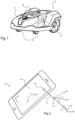
- Fig 1 shows an example of a robotic lawnmower 1 comprising rear driving wheels 3, which may be controlled individually, such that they also accomplish steering of the robotic lawnmower, and front caster wheels 5 that may be undriven, although different configurations are conceivable in the context of the present disclosure, such as 4-wheel driving configurations, articulated configurations, etc.
- the robotic lawnmower may have an outer housing 7 provided with markings 9, as will be discussed.
- the lawnmower is configured to autonomously process a work area in a structured or more or less random fashion depending on desired settings.
- the lawnmower is further configured to be or become aware of its position in the work area as well as the layout of the work area.
- the position sensing may be accomplished using a satellite navigation system, which may be enhanced using real-time kinematics, RTK, to obtain a precision of down to a few centimeters with regard to the lawnmower's position.
- RTK real-time kinematics
- other options are considered, such as providing a local navigation system, which the robotic lawnmower has access to, not depending on satellite navigation.
- augmented reality AR
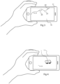
- a user interface is provided on a separate, mobile device 11 illustrated in fig 2 .
- the mobile device 11 comprises a built-in camera 13 and a display 15 which is capable of producing images taken by the camera and at the same time accomplish a user interface.
- the mobile device may typically be a smartphone or a tablet with touch-screen input capability, although other alternatives would be conceivable using other input means.
- the mobile device 11 typically has a GPS or other satellite navigation functionality allowing the mobile device to determine its position. Further, accelerometers/gyros in the mobile device 11 allows it to determine its orientation, both the orientation of the camera's 13 optical axis 17 in a three-dimensional coordinate system (x, y, z) and the mobile device's 11 roll angle ⁇ in relation to that optical axis 17. The accelerometers may also detect movements without change of orientation. Combinations of accelerometers gyros and magnetometers may be designated as an inertia measurement unit, IMU.
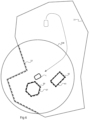
- a mobile device 11 in the form of a smartphone which provides on its display 15 an image of for instance a part of a garden which is simultaneously captured by the smartphone camera 13.
- virtual information such as a work area boundary 23 defined by a sequence of positions xb, yb, which are mapped between the work area and the display.
- the work area boundary 23 on the display moves correspondingly.
- the user can add a work area boundary 23 as the one illustrated using for instance a touch-screen functionality. It is also possible to edit an already entered boundary 23 by providing an updated section 25, for instance. It is possible to include an indication 24 regarding the quality of the position detection in the mobile device as will be discussed.
- the positions in the display 15 can be translated into positions in the garden or the like, which defines the work area for the robotic lawnmower 1. Those positions can thus transmitted to the robotic lawnmower 1 which may operate accordingly, typically remaining within an outer boundary, and optionally avoiding certain areas within that outer boundary, treating other areas according to certain schemes, etc.
- the mobile device 11 could detect its position and orientation with very high precision, it would have been possible for the user to move around for instance the entire periphery of a garden and define an outer work area boundary 23 within which the robotic lawnmower 1 is intended to operate and to transmit the corresponding position data to the robotic lawnmower 1.
- the mobile device's 11 position precision is however not sufficient for this purpose.
- Most mobile devices can use GPS or other satellite navigation features to acquire a rough position estimate. Accelerometers may resolve the orientation of the mobile device.
- visual odometry i.e. an analysis of camera image data in order to resolve changes in position and orientation of the mobile device, may be used to enhance accelerometer and GPS data. So called vSLAM-, visual simultaneous localization and mapping, -algorithms provide such functionality. However, this does not always provide data in the mobile device 11 with sufficiently high precision.
- the precision of the user interface is enhanced using the robotic lawnmower's 1 positioning system. If based for instance on RTK, that positioning system will have a high precision.
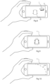
- Fig 4 illustrates how a user captures the robotic lawnmower 1 in the camera view of the mobile device 11.
- the robotic lawnmower 1 may communicate its position xr, yr to the mobile device. This allows for a more precise calibration of the mapping between the user interface on the mobile device 11 and actual positions xp, yp in the surroundings as sensed by the robotic lawnmower 1.
- the robotic lawnmower 1 senses its position with high precision for instance using RTK or similar technologies. By finding the lawnmower 1 in the image data and knowing the position of the robotic lawnmower 1 at that time, the combination of the position and the orientation of the mobile device 11 may be calibrated to a higher precision. This calibration may be achieved in different ways.
- the robotic lawnmower 1 It is possible to detect the heading of the robotic lawnmower 1 in the image. This may be facilitated by a heading indicating marking 9, cf. fig 1 and fig 5 , such as an arrow that facilitates the heading indication in the image. However, the shape of the robotic lawnmower 1 as a whole also indicates the heading to some extent.
- a visual guide 61 may be presented on the mobile device 11 user interface to indicate a suitable calibration position of the mobile device 11 in relation to the robotic lawnmower 1.
- the visual guide may for instance be a silhouette of the robotic lawnmower as seen from a specific direction and distance.
- the quality of the calibration may be improved as it may be made sure that the calibration takes place at a relatively small distance from the robotic lawnmower and with a predefined positional relationship between the robotic lawnmower 1 and the mobile device.
- a visual indication may be provided in the user interface.
- the aforementioned visual guide may change its appearance, e.g. may change color
- the robotic lawnmower 1 communicates its position xr, yr, zr at the time of calibration to the mobile device 11, allowing an application program in the mobile device to calibrate the mobile device position xm, ym, zm, and to resolve positions in the user interface thereafter, or it would be possible to simply record the image data and inputs produced when the user interacts with the user interface and thereafter transmitting the data to the robotic lawnmower 1 or another node and to determine an input work area boundary based on this data at another node in the systems besides the mobile device 11.
- the separate mobile device 11 may be in direct contact with the robotic lawnmower 1, via a wireless interface, such as Bluetooth or the like.
- the communication may take place via a third, remote node, or each of the robotic lawnmower and the separate mobile device may communicate with the third, remote node where coordination of data takes place. Regardless of this, the calibration and the subsequent recording and editing of work area data will result in position data which is sent to the robotic lawnmower 1 for use when processing the work area.
- the positioning of the mobile device 11 can be enhanced using this data, and the user can begin defining for instance an outer work area boundary nearby.
- the mobile device 11 becomes dependent on its own positioning and orientation determination. Therefore, the positioning of the mobile device 11 begins to drift in relation to the positioning determined by the robotic lawnmower 1.
- the mobile device can determine positions with a precision that is sufficient for reliable subsequent operation of the robotic lawnmower 1. This is illustrated with an example in fig 5 .
- the user intends to define outer borders 31 of a work area 30. This is done using a mobile device 11 as discussed above where the user can mark positions of the work area borders 31 in the user interface. Initially, the mobile device 11 detects the robotic lawnmower 1, and receives the robotic lawnmowers 1 current position, typically from the robotic lawnmower 1 itself, or from another node which is aware of this position. The mobile device 11 may receive this data via a short-range wireless interface such as BLUETOOTH.
- a short-range wireless interface such as BLUETOOTH.
- the user interface of the mobile device 11 can be considered calibrated into the positioning system of the robotic lawnmower 1.
- the user can begin registering segments 33 of the work area boundary 31 in the user interface.
- a zone 35 is defined in which the decrease in precision is acceptable. Typically this is corresponding to a radius from the calibration position as illustrated in fig 5 , but this may vary depending on how the mobile device is moved, when being distanced away from the robotic lawnmower 1, as will be discussed.
- zone 35A which can be designated as a capability zone.
- An indication of the limitations of the zone 35A is presented in the user interface of the mobile device 11. This can be done in different ways.
- the user interface may simply inform the user that he has reached or is close to reaching the edge of the capability zone, using text or a symbol. It is also possible in the user interface to disable recording of work area boundary segments 33 outside the capability zone 35. Another option, as illustrated in fig 3 , is to make a part 24 of an inputted segment 23 have a different appearance for being input outside the capability zone.
- a new capability zone 35B can be established as illustrated in fig 6 . Then, the user moves with the user interface 11, and the robotic lawnmower 1 moves with the user to a new position in the intended work area 30, or at least to a position close enough to the work area 30 such that a new capability zone 35B can be established which facilitates recording of new segments 33 along the intended work area boundary 31.
- the user thus calibrates the mobile device 11 positioning again by recording the robotic lawnmower 1 in the user interface as shown in fig 4 and receiving the current robotic lawnmower 1 position as detected by the robotic lawnmower 1 itself.
- This establishes the new capability zone 35B within which the mobile device 11 can record positions for new segments 33 of the intended work area. Note that this is not limited to the outer boundary 31 of the work area. It is also possible to detect positions for segments 37 of an exclusion zone 39 within the intended work area 31, e.g. a flower bed 39 that is not intended to be processed by the robotic lawnmower 1. Further, it is possible to register in the user interface segments 41 of a conditional zone 43 where processing should be carried out in a specific way or under certain conditions. For instance, some areas should not be cut during dry periods. All those segments 33, 37, 41 can be recorded within the new capability zone 35B.
- an entire work area 30 can be registered with one or more likely a few calibrations of the mobile device 11 with the robotic lawnmower 1.
- the robotic lawnmower 1 may move slightly from a first 51A to a second 51B position during a calibration event. Then, the robotic lawnmower 1 may report its position before and after the movement to the mobile device 11. This provides an improved calibration where more information relating to the distance between the mobile device 11 and the robotic lawnmower 1 is accomplished. Additionally, the heading of the robotic lawnmower is resolved.
- the capability zones 35A-D need not be circular with the last position given by the robotic lawnmower 1 at their centers. This may be considered an ideal capability zone. Depending on how the mobile device 11 is distanced from that position, the capability zone may be updated.
- that capability zone may be maintained to a greater extent than if a zig-zag pattern in moving towards the periphery is employed.
- the mobile device's 11 allowed capability of sequentially detecting positions while moving away from the last calibrated position 55 may be taken into account. For instance, if the mobile device 11 is pointed towards the ground and can continuously update its position also using visual odometry, the position detection may be better than if the camera is pointed towards the sky and the mobile device 11 only detects positions using accelerometers and/or satellite navigation or similar. The same applies if the satellite signals are obstructed by trees, for instance, resulting in poor positioning.
- the capability zone 35C shrinks, but situations where it is possible to restore or even expand the initial capability zone are also conceivable. For instance, if employing a vSLAM algorithm in the mobile device 11, it is possible that the algorithm recognizes a previously detected object and restores its precision from the last time that object was detected.
- the indication of the initial capability zone 35C may be gradually updated into an updated capability zone 35C' during use of the mobile device 11 for recording work area segments.
- the movement of the robotic lawnmower 1 between the points 51A/B, 53, 55, 57 where calibration takes place may be initiated in different ways. It is possible for the user, once he realizes that he has moved beyond a capability zone 35A to call for the robotic lawnmower 1 to move to his location in order to create a new capability zone. The mobile device 11 may then transmit its new position to the robotic lawnmower 1.
- This new position is determined with a relatively low precision it is sufficient for the robotic lawnmower to approach the user carrying the mobile device 11.
- This call to the robotic lawnmower 1 may also be sent automatically by the mobile device 11 which optionally may prompt the user to recalibrate with the robotic lawnmower once it has arrived.
- Another possibility is to let the robotic lawnmower 1 continuously follow the user with the mobile device 11, typically using position indications received from the mobile device.
- the present disclosure considers a corresponding data processing equipment comprising at least one processor and memory, and being configured to carry out the method.
- a corresponding computer program product for executing the method and a computer-readable storage medium having stored thereon the computer program is also considered.
- the above work area 30 may be defined by a set of coordinates in a geodetic system format such as WGS84, providing positions such as 57°51'10.4"N; 16°33'23.4"E.
- Other systems such as NAD83 may also be considered, as well as local coordinate systems intended specifically for lawnmowing or other similar purposes.
Landscapes
- Engineering & Computer Science (AREA)
- Physics & Mathematics (AREA)
- General Physics & Mathematics (AREA)
- Aviation & Aerospace Engineering (AREA)
- Radar, Positioning & Navigation (AREA)
- Remote Sensing (AREA)
- Automation & Control Theory (AREA)
- Computer Vision & Pattern Recognition (AREA)
- Theoretical Computer Science (AREA)
- Life Sciences & Earth Sciences (AREA)
- Environmental Sciences (AREA)
- Control Of Position, Course, Altitude, Or Attitude Of Moving Bodies (AREA)
Abstract
Description
- The present disclosure relates to a method for defining a boundary of a work area in a robotic lawnmower system, the system comprising a robotic lawnmower, configured to process the work area and to determine its position in the work area, and a separate, mobile device configured to determine its position in the work area and having a camera configured to capture images of the work area and a display which provides a user interface, enabling a user to define boundary segments of the work area boundary therein as a set of positions which are transferred to the robotic lawnmower.
- A robotic lawnmower system of this kind is disclosed in
EP-3767420-A1 where a work area is filmed using a mobile device, and borders in the work area are defined by sequentially placing virtual markers in a user interface illustrating images of the work area. In order to sense the mobile device's position in a global coordinate system, the charging station of the lawnmower and one other position with known coordinates are registered. The intention is to provide a navigation function in the robotic lawnmower that makes installing a boundary cable unnecessary. - In practice, the positions recorded with the mobile device may drift increasingly in relation to the global coordinate system in between said known positions, mobile device positioning usually rely on GPS, accelerometers and visual odometry, which cannot match RTK-based positioning. This implies that there may be differences between the positions sensed by the mobile device and actual position in the global coordinate system in which the robotic lawnmower navigates. This means that the positions in which the user believes to be placing the virtual markers, differ from the actual positions in the global coordinate system. If the robotic lawnmower is used based on those positions, this may result in grass being left uncut or in the robotic lawnmower processing areas which should be spared, for instance. The aforementioned document also describes an alternative method where the mobile device is used as a remote control, steering the robotic lawnmower along a path that defines the work area boundaries and recording the corresponding positions.
- One problem associated with prior art is therefore how to improve the definition of a work area boundary such that precision is improved.
- One object of the present disclosure is therefore to provide a robotic lawnmower system with improved precision.
- This object is achieved by means of a method in a robotic lawnmower system as defined in claim 1. More specifically, in a method of the initially mentioned kind, it is determined by calibrating, in a first position of the robotic lawnmower, and based on the position determined by the robotic lawnmower and the position of the robotic lawnmower in an image captured by the camera, a calibrated position of the mobile device. Based on this calibration, a capability zone is defined, within which the mobile device can sense positions with a minimum level of estimated alignment with respect to positions sensed by the robotic lawnmower. An indication of the limitations of the capability zone is presented in the user interface of the mobile device.
- In this way, the user can calibrate the position and orientation of the mobile device using the position sensed by the robotic lawnmower and can record segments of a work area boundary with high precision based on this calibration within the capability zone. This provides a work area boundary with improved precision that can be sent to the robotic lawnmower, which subsequently can process the work area with improved precision.
- The robotic lawnmower may subsequently be moved to a second position, where the calibration is repeated, and a second capability zone is defined. In this way, a large area can be covered with sufficient precision.
- In order to carry out this move, a request to move may be received from the user in the user interface, and a message may then be sent, invoking the robotic lawnmower to move to the proximity of the mobile device. This message may also be sent out automatically, without inputs from the user. Alternatively, the robotic lawnmower may be configured to follow the mobile device.
- It is possible to present a visual guide on the user interface to indicate a suitable calibration position in relation to the robotic work tool. This facilitates calibration, and ensures a suitable positional relation between the mobile device and the robotic lawnmower at calibration.
- A visual indication may be given in the user interface when calibration has taken place.
- It may be advantageous to detect the heading of the robotic work tool in the image when calibrating, and the robotic work tool may simultaneously report its heading to the mobile device. This provides an improved directional precision in the calibration.
- A movement of the robotic lawnmower may be carried out during each calibration in order to further improve the precision.
- The present disclosure also considers robotic lawnmower system, configured to carry out the steps of the above methods. Then, a robotic lawnmower system comprises a robotic lawnmower, configured to process a work area and to determine its position in the work area, and a separate, mobile device configured to determine its position in the work area and having a camera configured to capture images of the work area and a display which provides a user interface, enabling a user to define boundary segments of the work area boundary therein as a set of positions which are transferred to the robotic lawnmower, The system is configured to determine by calibrating, in a first position of the robotic lawnmower, and based on the position determined by the robotic lawnmower and the position of the robotic lawnmower in an image captured by said camera, a calibrated position of the mobile device. Further, the system defines, based on said calibration, a capability zone, within which the mobile device can sense positions with a minimum level of estimated alignment with respect to positions sensed by the robotic lawnmower, and is configured to present in the user interface of the mobile device an indication of the limitations of said capability zone. This system may be altered and varied in correspondence with the method, generally the system is then configured to carry out the corresponding steps of the method.
- The present disclosure also considers a processing equipment comprising at least one processor and memory, configured to carry out the above-defined method.
- The present disclosure also considers a computer program product having instructions which, when the program is executed on one or more processors, carries out the above-defined method.
- The present disclosure also considers a computer-readable storage medium having stored thereon the above computer program product.
-
-
Fig 1 illustrates a robotic lawnmower. -
Fig 2 illustrates a mobile device used to provide an AR interface. -
Fig 3 illustrates using a mobile device to record segments of a work area. -
Fig 4 illustrates the calibration of a mobile device using a robotic lawnmower. -
Fig 5 illustrates a first capability zone established after calibration of a mobile device. -
Fig 6 illustrates a second capability zone established after calibration of a mobile device. -
Fig 7 shows a sequence of capability zones used to record segments of a work area. -
Figs 8 and 9 illustrate the use of a visual guide in a user interface to carry out calibration. -
Fig 10 illustrates another example of indicating a capability zone in a user interface. - The present disclosure relates to robotic lawnmower systems. Such systems comprise a robotic lawnmower, or similar device, which is configured to process a work area. Further, a charging station, intermittently charging the lawnmower may be provided, although in the context of the present disclosure the charging station is not necessary.
-
Fig 1 shows an example of a robotic lawnmower 1 comprising rear driving wheels 3, which may be controlled individually, such that they also accomplish steering of the robotic lawnmower, andfront caster wheels 5 that may be undriven, although different configurations are conceivable in the context of the present disclosure, such as 4-wheel driving configurations, articulated configurations, etc. The robotic lawnmower may have an outer housing 7 provided with markings 9, as will be discussed. - The lawnmower is configured to autonomously process a work area in a structured or more or less random fashion depending on desired settings. The lawnmower is further configured to be or become aware of its position in the work area as well as the layout of the work area.
- The position sensing may be accomplished using a satellite navigation system, which may be enhanced using real-time kinematics, RTK, to obtain a precision of down to a few centimeters with regard to the lawnmower's position. However, in this disclosure, other options are considered, such as providing a local navigation system, which the robotic lawnmower has access to, not depending on satellite navigation.
- Methods exist to provide the robotic lawnmower with information regarding the work area in which a user wants the robotic lawnmower to operate. For instance, it has been suggested to lead the lawnmower around the outer boundary of the work area once, the lawnmower being remotely controlled, and letting the lawnmower record the positions of the outer boundary using its navigation system. This allows the robotic lawnmower to recognize its work area. This technique, sometimes referred to as "walk-the-dog", is relatively time-consuming and not very flexible. If the user decides to change the boundary to some extent, the process will likely need be repeated, even if the change is small.
- Therefore, in this context, the use of so-called augmented reality, AR, functions are considered a promising alternative. Then, a user interface is provided on a separate,
mobile device 11 illustrated infig 2 . - The
mobile device 11 comprises a built-incamera 13 and adisplay 15 which is capable of producing images taken by the camera and at the same time accomplish a user interface. The mobile device may typically be a smartphone or a tablet with touch-screen input capability, although other alternatives would be conceivable using other input means. - The
mobile device 11 typically has a GPS or other satellite navigation functionality allowing the mobile device to determine its position. Further, accelerometers/gyros in themobile device 11 allows it to determine its orientation, both the orientation of the camera's 13optical axis 17 in a three-dimensional coordinate system (x, y, z) and the mobile device's 11 roll angle φ in relation to thatoptical axis 17. The accelerometers may also detect movements without change of orientation. Combinations of accelerometers gyros and magnetometers may be designated as an inertia measurement unit, IMU. - Thereby, it is possible to provide a mapping between positions 19 (px, py, pz) in a work area depicted by the
camera 13 and a corresponding position 21 (ap, bp) in the mobile device's 11display 15. This makes it possible to display for instance a virtual work area boundary in the display, as an addition to the image captured by the camera. - This is illustrated with an example in
fig 3 , where the user uses amobile device 11 in the form of a smartphone which provides on itsdisplay 15 an image of for instance a part of a garden which is simultaneously captured by thesmartphone camera 13. In addition to this image, virtual information such as awork area boundary 23 defined by a sequence of positions xb, yb, which are mapped between the work area and the display. Thus, if the user changes the camera's view, thework area boundary 23 on the display moves correspondingly. In this interface, the user can add awork area boundary 23 as the one illustrated using for instance a touch-screen functionality. It is also possible to edit an already enteredboundary 23 by providing an updatedsection 25, for instance. It is possible to include anindication 24 regarding the quality of the position detection in the mobile device as will be discussed. - The positions in the
display 15 can be translated into positions in the garden or the like, which defines the work area for the robotic lawnmower 1. Those positions can thus transmitted to the robotic lawnmower 1 which may operate accordingly, typically remaining within an outer boundary, and optionally avoiding certain areas within that outer boundary, treating other areas according to certain schemes, etc. - In a hypothetical case where the
mobile device 11 could detect its position and orientation with very high precision, it would have been possible for the user to move around for instance the entire periphery of a garden and define an outerwork area boundary 23 within which the robotic lawnmower 1 is intended to operate and to transmit the corresponding position data to the robotic lawnmower 1. In most real applications however, the mobile device's 11 position precision is however not sufficient for this purpose. Most mobile devices can use GPS or other satellite navigation features to acquire a rough position estimate. Accelerometers may resolve the orientation of the mobile device. Further, visual odometry, i.e. an analysis of camera image data in order to resolve changes in position and orientation of the mobile device, may be used to enhance accelerometer and GPS data. So called vSLAM-, visual simultaneous localization and mapping, -algorithms provide such functionality. However, this does not always provide data in themobile device 11 with sufficiently high precision. - In the present disclosure, the precision of the user interface is enhanced using the robotic lawnmower's 1 positioning system. If based for instance on RTK, that positioning system will have a high precision.
-
Fig 4 illustrates how a user captures the robotic lawnmower 1 in the camera view of themobile device 11. At the same time, the robotic lawnmower 1 may communicate its position xr, yr to the mobile device. This allows for a more precise calibration of the mapping between the user interface on themobile device 11 and actual positions xp, yp in the surroundings as sensed by the robotic lawnmower 1. - The robotic lawnmower 1 as mentioned senses its position with high precision for instance using RTK or similar technologies. By finding the lawnmower 1 in the image data and knowing the position of the robotic lawnmower 1 at that time, the combination of the position and the orientation of the
mobile device 11 may be calibrated to a higher precision. This calibration may be achieved in different ways. - Either it is possible, using image analysis, to detect the robotic lawnmower in the image data, or it is possible to prompt the user to point the
mobile device 11 in such a way that the robotic lawnmower is located in a particular portion of the camera's view and to indicate when this is the case as will be discussed. Those alternatives could also be combined such that the user pointing the camera view in a particular way simplifies an image analysis based detection of the robotic lawnmower's location in the view. - It is possible to detect the heading of the robotic lawnmower 1 in the image. This may be facilitated by a heading indicating marking 9, cf.
fig 1 andfig 5 , such as an arrow that facilitates the heading indication in the image. However, the shape of the robotic lawnmower 1 as a whole also indicates the heading to some extent. - With reference to an example in
figs 8 an 9, avisual guide 61 may be presented on themobile device 11 user interface to indicate a suitable calibration position of themobile device 11 in relation to the robotic lawnmower 1. The visual guide may for instance be a silhouette of the robotic lawnmower as seen from a specific direction and distance. - If the user moves and directs the
mobile device 11 such that thevisual guide 61 coincides with the robotic lawnmower 1, this facilitates the detection of therobotic lawnmower 11 in the image. Further, the quality of the calibration may be improved as it may be made sure that the calibration takes place at a relatively small distance from the robotic lawnmower and with a predefined positional relationship between the robotic lawnmower 1 and the mobile device. As shown infig 9 , there may be given feedback to the user when calibration has taken place, for instance a visual indication may be provided in the user interface. In one example, the aforementioned visual guide may change its appearance, e.g. may change color - Returning to
fig 4 and5 , it is possible to let the robotic lawnmower 1 communicate its position xr, yr, zr at the time of calibration to themobile device 11, allowing an application program in the mobile device to calibrate the mobile device position xm, ym, zm, and to resolve positions in the user interface thereafter, or it would be possible to simply record the image data and inputs produced when the user interacts with the user interface and thereafter transmitting the data to the robotic lawnmower 1 or another node and to determine an input work area boundary based on this data at another node in the systems besides themobile device 11. - Typically, the separate
mobile device 11 may be in direct contact with the robotic lawnmower 1, via a wireless interface, such as Bluetooth or the like. Alternatively, the communication may take place via a third, remote node, or each of the robotic lawnmower and the separate mobile device may communicate with the third, remote node where coordination of data takes place. Regardless of this, the calibration and the subsequent recording and editing of work area data will result in position data which is sent to the robotic lawnmower 1 for use when processing the work area. - In the case where the robotic lawnmower 1 communicates its position to the
mobile device 11 at a point of time where the robotic lawnmower 1 is in the camera view of themobile device 11, the positioning of themobile device 11 can be enhanced using this data, and the user can begin defining for instance an outer work area boundary nearby. However, as soon as the robotic lawnmower 1 leaves the camera view, themobile device 11 becomes dependent on its own positioning and orientation determination. Therefore, the positioning of themobile device 11 begins to drift in relation to the positioning determined by the robotic lawnmower 1. - However, within an area near the robotic lawnmower 1, the mobile device can determine positions with a precision that is sufficient for reliable subsequent operation of the robotic lawnmower 1. This is illustrated with an example in
fig 5 . - In
fig 5 , the user intends to defineouter borders 31 of awork area 30. This is done using amobile device 11 as discussed above where the user can mark positions of the work area borders 31 in the user interface. Initially, themobile device 11 detects the robotic lawnmower 1, and receives the robotic lawnmowers 1 current position, typically from the robotic lawnmower 1 itself, or from another node which is aware of this position. Themobile device 11 may receive this data via a short-range wireless interface such as BLUETOOTH. - When the
mobile device 11 has associated the robotic lawnmower 1 in its camera view with the corresponding received position, the user interface of themobile device 11 can be considered calibrated into the positioning system of the robotic lawnmower 1. Thus, the user can begin registeringsegments 33 of thework area boundary 31 in the user interface. - As the
mobile device 11 moves away from the lawnmower 1, the precision of the mobile device's 11 position detection decreases. In the present disclosure, a zone 35 is defined in which the decrease in precision is acceptable. Typically this is corresponding to a radius from the calibration position as illustrated infig 5 , but this may vary depending on how the mobile device is moved, when being distanced away from the robotic lawnmower 1, as will be discussed. - Then, when the user registers
segments 33 of the work area, this can be done satisfactorily within thezone 35A , which can be designated as a capability zone. - An indication of the limitations of the
zone 35A is presented in the user interface of themobile device 11. This can be done in different ways. - For instance, the user interface may simply inform the user that he has reached or is close to reaching the edge of the capability zone, using text or a symbol. It is also possible in the user interface to disable recording of work
area boundary segments 33 outside the capability zone 35. Another option, as illustrated infig 3 , is to make apart 24 of an inputtedsegment 23 have a different appearance for being input outside the capability zone. - It is also possible to apply different color filters, in the presented image filmed in the garden or the like, depending on whether positions in the image are inside or outside the
capability zone 35A or simply to superimpose the boundary of thecapability zone 35A in the image as illustrated infig 10 . - As illustrated in
fig 5 , only a portion of an intendedwork area 31 is within the capability zone 35. Therefore, somesegments 33 of the intendedwork area boundary 31 can be registered but not the entirety thereof. - Therefore, a
new capability zone 35B can be established as illustrated infig 6 . Then, the user moves with theuser interface 11, and the robotic lawnmower 1 moves with the user to a new position in the intendedwork area 30, or at least to a position close enough to thework area 30 such that anew capability zone 35B can be established which facilitates recording ofnew segments 33 along the intendedwork area boundary 31. - The user thus calibrates the
mobile device 11 positioning again by recording the robotic lawnmower 1 in the user interface as shown infig 4 and receiving the current robotic lawnmower 1 position as detected by the robotic lawnmower 1 itself. This establishes thenew capability zone 35B within which themobile device 11 can record positions fornew segments 33 of the intended work area. Note that this is not limited to theouter boundary 31 of the work area. It is also possible to detect positions for segments 37 of anexclusion zone 39 within the intendedwork area 31, e.g. aflower bed 39 that is not intended to be processed by the robotic lawnmower 1. Further, it is possible to register in the user interface segments 41 of aconditional zone 43 where processing should be carried out in a specific way or under certain conditions. For instance, some areas should not be cut during dry periods. All thosesegments 33, 37, 41 can be recorded within thenew capability zone 35B. - In this way, an
entire work area 30 can be registered with one or more likely a few calibrations of themobile device 11 with the robotic lawnmower 1. In the work area illustrated infig 7 , it would be possible to calibrate themobile device 11 with the robotic work tool 1 at four different locations 51A/B, 53, 55, 57, thereby successively achieving fourdifferent capability zones work area boundary 31 can be recorded with sufficient precision. - It is possible, as illustrated with an example in
fig 7 , to make the robotic lawnmower 1 move slightly from a first 51A to a second 51B position during a calibration event. Then, the robotic lawnmower 1 may report its position before and after the movement to themobile device 11. This provides an improved calibration where more information relating to the distance between themobile device 11 and the robotic lawnmower 1 is accomplished. Additionally, the heading of the robotic lawnmower is resolved. - As mentioned, the
capability zones 35A-D need not be circular with the last position given by the robotic lawnmower 1 at their centers. This may be considered an ideal capability zone. Depending on how themobile device 11 is distanced from that position, the capability zone may be updated. - As one example, moving away from a last calibrated
position 55 in a straight line towards the periphery of thecapability zone 35C, that capability zone may be maintained to a greater extent than if a zig-zag pattern in moving towards the periphery is employed. - Also, the mobile device's 11 allowed capability of sequentially detecting positions while moving away from the last calibrated
position 55 may be taken into account. For instance, if themobile device 11 is pointed towards the ground and can continuously update its position also using visual odometry, the position detection may be better than if the camera is pointed towards the sky and themobile device 11 only detects positions using accelerometers and/or satellite navigation or similar. The same applies if the satellite signals are obstructed by trees, for instance, resulting in poor positioning. - In the above examples, the
capability zone 35C shrinks, but situations where it is possible to restore or even expand the initial capability zone are also conceivable. For instance, if employing a vSLAM algorithm in themobile device 11, it is possible that the algorithm recognizes a previously detected object and restores its precision from the last time that object was detected. - Therefore, the indication of the
initial capability zone 35C may be gradually updated into an updatedcapability zone 35C' during use of themobile device 11 for recording work area segments. - The movement of the robotic lawnmower 1 between the points 51A/B, 53, 55, 57 where calibration takes place may be initiated in different ways. It is possible for the user, once he realizes that he has moved beyond a
capability zone 35A to call for the robotic lawnmower 1 to move to his location in order to create a new capability zone. Themobile device 11 may then transmit its new position to the robotic lawnmower 1. - Although this new position is determined with a relatively low precision it is sufficient for the robotic lawnmower to approach the user carrying the
mobile device 11. This call to the robotic lawnmower 1 may also be sent automatically by themobile device 11 which optionally may prompt the user to recalibrate with the robotic lawnmower once it has arrived. - Another possibility is to let the robotic lawnmower 1 continuously follow the user with the
mobile device 11, typically using position indications received from the mobile device. - In addition to the method and system described above, the present disclosure considers a corresponding data processing equipment comprising at least one processor and memory, and being configured to carry out the method. A corresponding computer program product for executing the method and a computer-readable storage medium having stored thereon the computer program is also considered.
- The
above work area 30 may be defined by a set of coordinates in a geodetic system format such as WGS84, providing positions such as 57°51'10.4"N; 16°33'23.4"E. Other systems such as NAD83 may also be considered, as well as local coordinate systems intended specifically for lawnmowing or other similar purposes. - The invention is not restricted to the described embodiments and may be varied and altered in different ways within the scope of the appended claims.
Claims (12)
- A method for defining a boundary (31, 39) of a work area (30) in a robotic lawnmower system, the system comprising- a robotic lawnmower (1), configured to process the work area (30) and to determine its position (xr, yr, zr) in the work area, and- a separate, mobile device (11) configured to determine its position (xm, ym, zm) in the work area (30) and having a camera (13) configured to capture images of the work area (30) and a display (15) which provides a user interface, enabling a user to define boundary segments (33, 37) of the work area boundary (31, 39) therein as a set of positions which are transferred to the robotic lawnmower (1), characterized by- determining by calibrating, in a first position (51) of the robotic lawnmower, and based on the position (xr, yr, zr) determined by the robotic lawnmower (1) and the position of the robotic lawnmower in an image captured by said camera (13), a calibrated position (xm+, ym+, zm+) of the mobile device (11),- defining, based on said calibration, a first capability zone (35A), within which the mobile device (1) can sense positions with minimum level of estimated alignment with respect to positions sensed by the robotic lawnmower (1), and- presenting in the user interface of the mobile device (11) an indication (24) of the limitations of said first capability zone (35A).
- Method according to claim 1, wherein the robotic lawnmower (1) is subsequently moved to a second position (53), the calibration is repeated and a second capability zone (35B) is defined.
- Method according to claim 2, wherein a request to move is received in the user interface, and a message is sent invoking the robotic lawnmower (1) to move to the proximity of the mobile device (11).
- Method according to claim 2, wherein the robotic lawnmower (1) is configured to follow the mobile device (11).
- Method according to any of the preceding claims wherein a visual guide (61) is presented on the user interface to indicate a suitable calibration position in relation to the robotic work tool.
- Method according to claim 5, wherein a visual indication is given in the user interface when calibration has taken place.
- Method according to any of the preceding claims wherein the heading of the robotic work tool is detected in the image, and the robotic work tool reports its heading to the mobile device.
- Method according to any of the preceding claims, wherein a movement (51A, 51B) of the robotic lawnmower (1) is carried out in each calibration.
- A robotic lawnmower system comprising- a robotic lawnmower (1), configured to process a work area (30) and to determine its position (xr, yr, zr) in the work area, and- a separate, mobile device (11) configured to determine its position (xm, ym, zm) in the work area (30) and having a camera (13) configured to capture images of the work area (30) and a display (15) which provides a user interface, enabling a user to define boundary segments (33, 37) of the work area boundary (31, 39) therein as a set of positions which are transferred to the robotic lawnmower (1), characterized by the system being configured to- determine by calibrating, in a first position (51) of the robotic lawnmower, and based on the position (xr, yr, zr) determined by the robotic lawnmower (1) and the position of the robotic lawnmower in an image captured by said camera (13), a calibrated position (xm+, ym+, zm+) of the mobile device (11),- define, based on said calibration, a capability zone (35A), within which the mobile device (1) can sense positions with minimum level of estimated alignment with respect to positions sensed by the robotic lawnmower (1), and- present in the user interface of the mobile device (11) an indication (24) of the limitations of said capability zone.
- Data processing equipment comprising at least one processor and memory, configured to carry out the method of any of the claims 1-8.
- A computer program product comprising instructions which, when the program is executed on a processor, carries out the method according to any of the claims 1-8.
- A computer-readable storage medium having stored thereon the computer program product of claim 11.
Applications Claiming Priority (1)
| Application Number | Priority Date | Filing Date | Title |
|---|---|---|---|
| SE2351321A SE548230C2 (en) | 2023-11-20 | 2023-11-20 | Method and robotic lawnmower system for defining a boundary of a work area |
Publications (2)
| Publication Number | Publication Date |
|---|---|
| EP4557035A1 true EP4557035A1 (en) | 2025-05-21 |
| EP4557035B1 EP4557035B1 (en) | 2026-04-15 |
Family
ID=93334347
Family Applications (1)
| Application Number | Title | Priority Date | Filing Date |
|---|---|---|---|
| EP24209757.4A Active EP4557035B1 (en) | 2023-11-20 | 2024-10-30 | Robotic lawnmower system |
Country Status (2)
| Country | Link |
|---|---|
| EP (1) | EP4557035B1 (en) |
| SE (1) | SE548230C2 (en) |
Citations (2)
| Publication number | Priority date | Publication date | Assignee | Title |
|---|---|---|---|---|
| EP3767420A1 (en) | 2019-07-15 | 2021-01-20 | Deere & Company | Robotic mower boundary detection system |
| CN115811702A (en) * | 2021-09-14 | 2023-03-17 | 科沃斯机器人股份有限公司 | Working area determination method, device, equipment and readable storage medium |
Family Cites Families (4)
| Publication number | Priority date | Publication date | Assignee | Title |
|---|---|---|---|---|
| CA3160530A1 (en) * | 2019-11-27 | 2021-06-03 | The Toro Company | Autonomous machine navigation in various lighting environments |
| CN114721385A (en) * | 2022-04-07 | 2022-07-08 | 未岚大陆(北京)科技有限公司 | Virtual boundary establishing method and device, intelligent terminal and computer storage medium |
| CN116974275A (en) * | 2022-04-28 | 2023-10-31 | 创科无线普通合伙 | Creating virtual boundaries for robotic garden tools |
| EP4270138A1 (en) * | 2022-04-28 | 2023-11-01 | Techtronic Cordless GP | Creation of a virtual boundary for a robotic garden tool |
-
2023
- 2023-11-20 SE SE2351321A patent/SE548230C2/en unknown
-
2024
- 2024-10-30 EP EP24209757.4A patent/EP4557035B1/en active Active
Patent Citations (2)
| Publication number | Priority date | Publication date | Assignee | Title |
|---|---|---|---|---|
| EP3767420A1 (en) | 2019-07-15 | 2021-01-20 | Deere & Company | Robotic mower boundary detection system |
| CN115811702A (en) * | 2021-09-14 | 2023-03-17 | 科沃斯机器人股份有限公司 | Working area determination method, device, equipment and readable storage medium |
Also Published As
| Publication number | Publication date |
|---|---|
| SE548230C2 (en) | 2026-04-27 |
| SE2351321A1 (en) | 2025-05-21 |
| EP4557035B1 (en) | 2026-04-15 |
Similar Documents
| Publication | Publication Date | Title |
|---|---|---|
| EP3351077B1 (en) | Travel route generation device and travel route generation program | |
| US9684305B2 (en) | System and method for mobile robot teleoperation | |
| US8392036B2 (en) | Point and go navigation system and method | |
| CN205024577U (en) | Self -walking -type building machine | |
| EP3627269A1 (en) | Target tracking method and apparatus, mobile device and storage medium | |
| EP3168705A1 (en) | Domestic robotic system | |
| CA3066764A1 (en) | 3-d image system for vehicle control | |
| US11029707B2 (en) | Moving object, moving object control method, moving object control system, and moving object control program | |
| JP7142597B2 (en) | Running area shape registration system | |
| JP5187757B2 (en) | Unmanned mobile system | |
| WO2018191818A1 (en) | Stand-alone self-driving material-transport vehicle | |
| EP4660968A2 (en) | Method for determining virtual work boundary and mower | |
| KR101132713B1 (en) | Device for control of moving robot, moving robot system having the same and method for control of moving robot | |
| JP6949417B1 (en) | Vehicle maneuvering system and vehicle maneuvering method | |
| KR20210068383A (en) | Method for recognizing worker position in manufacturing line and apparatus thereof | |
| CN120276470B (en) | Speed synchronization control method for unmanned aerial vehicle and mobile platform, flight control system and unmanned aerial vehicle | |
| US11573565B2 (en) | Controller for an unmanned aerial vehicle | |
| EP4557035B1 (en) | Robotic lawnmower system | |
| CN213999507U (en) | Mobile robot system | |
| CN115811702B (en) | Methods, apparatus, equipment and readable storage media for determining working area | |
| CN116125973A (en) | Regression docking method and system of self-moving robot and self-moving robot | |
| EP4575693A1 (en) | Robotic lawnmower system | |
| EP4575694A1 (en) | Robotic lawnmower system | |
| JP2022065749A (en) | Control system for movable body | |
| SE2251485A1 (en) | Robotic lawnmower system with an augmented reality user interface |
Legal Events
| Date | Code | Title | Description |
|---|---|---|---|
| PUAI | Public reference made under article 153(3) epc to a published international application that has entered the european phase |
Free format text: ORIGINAL CODE: 0009012 |
|
| STAA | Information on the status of an ep patent application or granted ep patent |
Free format text: STATUS: THE APPLICATION HAS BEEN PUBLISHED |
|
| AK | Designated contracting states |
Kind code of ref document: A1 Designated state(s): AL AT BE BG CH CY CZ DE DK EE ES FI FR GB GR HR HU IE IS IT LI LT LU LV MC ME MK MT NL NO PL PT RO RS SE SI SK SM TR |
|
| STAA | Information on the status of an ep patent application or granted ep patent |
Free format text: STATUS: REQUEST FOR EXAMINATION WAS MADE |
|
| 17P | Request for examination filed |
Effective date: 20251028 |
|
| GRAP | Despatch of communication of intention to grant a patent |
Free format text: ORIGINAL CODE: EPIDOSNIGR1 |
|
| STAA | Information on the status of an ep patent application or granted ep patent |
Free format text: STATUS: GRANT OF PATENT IS INTENDED |
|
| INTG | Intention to grant announced |
Effective date: 20251211 |
|
| GRAS | Grant fee paid |
Free format text: ORIGINAL CODE: EPIDOSNIGR3 |
|
| GRAA | (expected) grant |
Free format text: ORIGINAL CODE: 0009210 |
|
| STAA | Information on the status of an ep patent application or granted ep patent |
Free format text: STATUS: THE PATENT HAS BEEN GRANTED |
|
| AK | Designated contracting states |
Kind code of ref document: B1 Designated state(s): AL AT BE BG CH CY CZ DE DK EE ES FI FR GB GR HR HU IE IS IT LI LT LU LV MC ME MK MT NL NO PL PT RO RS SE SI SK SM TR |
|
| REG | Reference to a national code |
Ref country code: CH Ref legal event code: F10 Free format text: ST27 STATUS EVENT CODE: U-0-0-F10-F00 (AS PROVIDED BY THE NATIONAL OFFICE) Effective date: 20260415 |
|
| REG | Reference to a national code |
Ref country code: DE Ref legal event code: R096 Ref document number: 602024003982 Country of ref document: DE |