EP4556842A1 - Heat exchanger - Google Patents
Heat exchanger Download PDFInfo
- Publication number
- EP4556842A1 EP4556842A1 EP24841093.8A EP24841093A EP4556842A1 EP 4556842 A1 EP4556842 A1 EP 4556842A1 EP 24841093 A EP24841093 A EP 24841093A EP 4556842 A1 EP4556842 A1 EP 4556842A1
- Authority
- EP
- European Patent Office
- Prior art keywords
- flow path
- liquid
- heat exchanger
- gas
- refrigerant
- Prior art date
- Legal status (The legal status is an assumption and is not a legal conclusion. Google has not performed a legal analysis and makes no representation as to the accuracy of the status listed.)
- Pending
Links
Images








Classifications
-
- F—MECHANICAL ENGINEERING; LIGHTING; HEATING; WEAPONS; BLASTING
- F28—HEAT EXCHANGE IN GENERAL
- F28D—HEAT-EXCHANGE APPARATUS, NOT PROVIDED FOR IN ANOTHER SUBCLASS, IN WHICH THE HEAT-EXCHANGE MEDIA DO NOT COME INTO DIRECT CONTACT
- F28D1/00—Heat-exchange apparatus having stationary conduit assemblies for one heat-exchange medium only, the media being in contact with different sides of the conduit wall, in which the other heat-exchange medium is a large body of fluid, e.g. domestic or motor car radiators
- F28D1/02—Heat-exchange apparatus having stationary conduit assemblies for one heat-exchange medium only, the media being in contact with different sides of the conduit wall, in which the other heat-exchange medium is a large body of fluid, e.g. domestic or motor car radiators with heat-exchange conduits immersed in the body of fluid
- F28D1/04—Heat-exchange apparatus having stationary conduit assemblies for one heat-exchange medium only, the media being in contact with different sides of the conduit wall, in which the other heat-exchange medium is a large body of fluid, e.g. domestic or motor car radiators with heat-exchange conduits immersed in the body of fluid with tubular conduits
- F28D1/047—Heat-exchange apparatus having stationary conduit assemblies for one heat-exchange medium only, the media being in contact with different sides of the conduit wall, in which the other heat-exchange medium is a large body of fluid, e.g. domestic or motor car radiators with heat-exchange conduits immersed in the body of fluid with tubular conduits the conduits being bent, e.g. in a serpentine or zig-zag
- F28D1/0471—Heat-exchange apparatus having stationary conduit assemblies for one heat-exchange medium only, the media being in contact with different sides of the conduit wall, in which the other heat-exchange medium is a large body of fluid, e.g. domestic or motor car radiators with heat-exchange conduits immersed in the body of fluid with tubular conduits the conduits being bent, e.g. in a serpentine or zig-zag the conduits having a non-circular cross-section
-
- F—MECHANICAL ENGINEERING; LIGHTING; HEATING; WEAPONS; BLASTING
- F25—REFRIGERATION OR COOLING; COMBINED HEATING AND REFRIGERATION SYSTEMS; HEAT PUMP SYSTEMS; MANUFACTURE OR STORAGE OF ICE; LIQUEFACTION SOLIDIFICATION OF GASES
- F25B—REFRIGERATION MACHINES, PLANTS OR SYSTEMS; COMBINED HEATING AND REFRIGERATION SYSTEMS; HEAT PUMP SYSTEMS
- F25B39/00—Evaporators; Condensers
-
- F—MECHANICAL ENGINEERING; LIGHTING; HEATING; WEAPONS; BLASTING
- F25—REFRIGERATION OR COOLING; COMBINED HEATING AND REFRIGERATION SYSTEMS; HEAT PUMP SYSTEMS; MANUFACTURE OR STORAGE OF ICE; LIQUEFACTION SOLIDIFICATION OF GASES
- F25B—REFRIGERATION MACHINES, PLANTS OR SYSTEMS; COMBINED HEATING AND REFRIGERATION SYSTEMS; HEAT PUMP SYSTEMS
- F25B39/00—Evaporators; Condensers
- F25B39/02—Evaporators
-
- F—MECHANICAL ENGINEERING; LIGHTING; HEATING; WEAPONS; BLASTING
- F25—REFRIGERATION OR COOLING; COMBINED HEATING AND REFRIGERATION SYSTEMS; HEAT PUMP SYSTEMS; MANUFACTURE OR STORAGE OF ICE; LIQUEFACTION SOLIDIFICATION OF GASES
- F25B—REFRIGERATION MACHINES, PLANTS OR SYSTEMS; COMBINED HEATING AND REFRIGERATION SYSTEMS; HEAT PUMP SYSTEMS
- F25B49/00—Arrangement or mounting of control or safety devices
- F25B49/02—Arrangement or mounting of control or safety devices for compression type machines, plants or systems
-
- F—MECHANICAL ENGINEERING; LIGHTING; HEATING; WEAPONS; BLASTING
- F28—HEAT EXCHANGE IN GENERAL
- F28D—HEAT-EXCHANGE APPARATUS, NOT PROVIDED FOR IN ANOTHER SUBCLASS, IN WHICH THE HEAT-EXCHANGE MEDIA DO NOT COME INTO DIRECT CONTACT
- F28D1/00—Heat-exchange apparatus having stationary conduit assemblies for one heat-exchange medium only, the media being in contact with different sides of the conduit wall, in which the other heat-exchange medium is a large body of fluid, e.g. domestic or motor car radiators
- F28D1/02—Heat-exchange apparatus having stationary conduit assemblies for one heat-exchange medium only, the media being in contact with different sides of the conduit wall, in which the other heat-exchange medium is a large body of fluid, e.g. domestic or motor car radiators with heat-exchange conduits immersed in the body of fluid
- F28D1/04—Heat-exchange apparatus having stationary conduit assemblies for one heat-exchange medium only, the media being in contact with different sides of the conduit wall, in which the other heat-exchange medium is a large body of fluid, e.g. domestic or motor car radiators with heat-exchange conduits immersed in the body of fluid with tubular conduits
- F28D1/053—Heat-exchange apparatus having stationary conduit assemblies for one heat-exchange medium only, the media being in contact with different sides of the conduit wall, in which the other heat-exchange medium is a large body of fluid, e.g. domestic or motor car radiators with heat-exchange conduits immersed in the body of fluid with tubular conduits the conduits being straight
- F28D1/0535—Heat-exchange apparatus having stationary conduit assemblies for one heat-exchange medium only, the media being in contact with different sides of the conduit wall, in which the other heat-exchange medium is a large body of fluid, e.g. domestic or motor car radiators with heat-exchange conduits immersed in the body of fluid with tubular conduits the conduits being straight the conduits having a non-circular cross-section
- F28D1/05366—Assemblies of conduits connected to common headers, e.g. core type radiators
- F28D1/05391—Assemblies of conduits connected to common headers, e.g. core type radiators with multiple rows of conduits or with multi-channel conduits combined with a particular flow pattern, e.g. multi-row multi-stage radiators
-
- F—MECHANICAL ENGINEERING; LIGHTING; HEATING; WEAPONS; BLASTING
- F28—HEAT EXCHANGE IN GENERAL
- F28F—DETAILS OF HEAT-EXCHANGE AND HEAT-TRANSFER APPARATUS, OF GENERAL APPLICATION
- F28F9/00—Casings; Header boxes; Auxiliary supports for elements; Auxiliary members within casings
- F28F9/02—Header boxes; End plates
- F28F9/026—Header boxes; End plates with static flow control means, e.g. with means for uniformly distributing heat exchange media into conduits
- F28F9/0278—Header boxes; End plates with static flow control means, e.g. with means for uniformly distributing heat exchange media into conduits in the form of stacked distribution plates or perforated plates arranged over end plates
-
- F—MECHANICAL ENGINEERING; LIGHTING; HEATING; WEAPONS; BLASTING
- F28—HEAT EXCHANGE IN GENERAL
- F28F—DETAILS OF HEAT-EXCHANGE AND HEAT-TRANSFER APPARATUS, OF GENERAL APPLICATION
- F28F1/00—Tubular elements; Assemblies of tubular elements
- F28F1/10—Tubular elements and assemblies thereof with means for increasing heat-transfer area, e.g. with fins, with projections, with recesses
- F28F1/12—Tubular elements and assemblies thereof with means for increasing heat-transfer area, e.g. with fins, with projections, with recesses the means being only outside the tubular element
- F28F1/24—Tubular elements and assemblies thereof with means for increasing heat-transfer area, e.g. with fins, with projections, with recesses the means being only outside the tubular element and extending transversely
- F28F1/32—Tubular elements and assemblies thereof with means for increasing heat-transfer area, e.g. with fins, with projections, with recesses the means being only outside the tubular element and extending transversely the means having portions engaging further tubular elements
-
- F—MECHANICAL ENGINEERING; LIGHTING; HEATING; WEAPONS; BLASTING
- F28—HEAT EXCHANGE IN GENERAL
- F28F—DETAILS OF HEAT-EXCHANGE AND HEAT-TRANSFER APPARATUS, OF GENERAL APPLICATION
- F28F2215/00—Fins
- F28F2215/12—Fins with U-shaped slots for laterally inserting conduits
Definitions
- the present invention relates to a heat exchanger.
- a plurality of heat transfer tubes are connected to a header in which a refrigerant is split and distributed to the heat transfer tubes.
- a heat exchanger includes a header and a plurality of heat transfer tubes.
- the plurality of heat transfer tubes are connected to the header.
- the header includes a first flow path, a second flow path, and a third flow path.
- the first flow path, the second flow path, and the third flow path are connected at a connecting portion.
- the first flow path extends in a first direction which is a vertical direction.
- the second flow path extends in a second direction.
- the third flow path extends in a third direction.
- the second direction and the third direction have symmetry with respect to a virtual plane including a line extending in the vertical direction from the connecting portion and a line extending in a direction in which the heat transfer tubes extend from the connecting portion.
- the first flow path includes a first narrowed portion.
- a heat exchanger according to a second aspect is the heat exchanger according to the first aspect, wherein the second direction and the third direction are horizontal directions.
- a heat exchanger according to a third aspect is the heat exchanger according to the first aspect or the second aspect, wherein the first narrowed portion is connected to the connecting portion.
- a heat exchanger according to a fourth aspect is the heat exchanger according to the third aspect, wherein the first narrowed portion is positioned above the connecting portion.
- a heat exchanger according to a fifth aspect is the heat exchanger according to any of the first aspect to the fourth aspect, wherein the header is a stacked header in which a plurality of plate members including a first plate member are stacked. The first plate member forms the first flow path, the second flow path, and the third flow path.
- the first plate member may form at least a part of the first flow path, at least a part of the second flow path, and at least a part of the third flow path.
- a heat exchanger according to a sixth aspect is the heat exchanger according to any of the first aspect to the fifth aspect, wherein the second flow path includes a second narrowed portion.
- the third flow path includes a third narrowed portion.
- a heat exchanger according to a seventh aspect is the heat exchanger according to any of the first aspect to the sixth aspect, wherein the flow path area of the second flow path and the flow path area of the third flow path are the same.
- the flow path length of the second flow path and the flow path length of the third flow path are the same.
- the degree of pressure loss when the refrigerant flows through the second flow path and the degree of pressure loss when the refrigerant flows through the third flow path can be made close to each other.
- a heat exchanger is the heat exchanger according to any of the first aspect to the seventh aspect, further comprising a fourth flow path and a fifth flow path.
- the fourth flow path is connected to the second flow path and extends in a direction different from the direction in which the second flow path extends.
- the fifth flow path is connected to the third flow path and extends in a direction different from the direction in which the third flow path extends.
- the refrigerant flowing through the second flow path can be guided in a direction different from the direction in which the second flow path extends, and the refrigerant flowing through the third flow path can be guided in a direction different from the direction in which the third flow path extends.
- a heat exchanger according to a ninth aspect is the heat exchanger according to the eighth aspect, wherein both the fourth flow path and the fifth flow path extend upward, or both the fourth flow path and the fifth flow path extend downward.
- a heat exchanger is the heat exchanger according to the eighth aspect or the ninth aspect, wherein the second flow path includes a first protrusion.
- the first protrusion protrudes toward the opposite side to the connecting portion side with respect to a connection area between the second flow path and the fourth flow path in the direction in which the second flow path extends.
- the third flow path has a second protrusion.
- the second protrusion protrudes toward the opposite side to the connecting portion side with respect to a connection area between the third flow path and the fifth flow path in the direction in which the third flow path extends.
- a heat exchanger according to an eleventh aspect is the heat exchanger according to any of the eighth aspect to the tenth aspect, wherein the fourth flow path includes a fourth narrowed portion.
- the fifth flow path includes a fifth narrowed portion.
- the refrigerant that has passed through the fourth narrowed portion easily reaches the end part of the fourth flow path, and the refrigerant that has passed through the fifth narrowed portion easily reaches the end part of the fifth flow path.
- a heat exchanger is the heat exchanger according to any of the eighth aspect to the eleventh aspect, further comprising a first connection pipe having both ends connected to the header, and a second connection pipe having both ends connected to the header.
- the first connection pipe constitutes at least a part of a flow path connecting the fourth flow path and a sixth flow path which is a flow path inside the header.
- the second connection pipe constitutes at least a part of a flow path connecting the fifth flow path and a seventh flow path which is a flow path inside the header.
- the refrigerant sent to the fourth flow path can be guided to the sixth flow path, which is a flow path inside the header spaced apart from the fourth flow path, and the refrigerant sent to the fifth flow path can be guided to the seventh flow path, which is a flow path inside the header spaced apart from the fifth flow path.
- a heat exchanger according to a thirteenth aspect is the heat exchanger according to any of the first aspect to the twelfth aspect, wherein the first flow path has a first portion having a flow path cross-sectional area larger than that of the first narrowed portion.
- the flow path cross-sectional area of the second flow path and the flow path cross-sectional area of the third flow path are smaller than the flow path cross-sectional area of the first portion.
- a heat exchanger is the heat exchanger according to any of the first aspect to the thirteenth aspect, wherein the header includes a plate-shaped member in which a first opening part and a second opening part are formed.
- the first opening part forms at least a part of the connecting portion, the first flow path, the second flow path, and the third flow path.
- the second opening is isolated from the first opening part, and forms an eighth flow path which is a flow path other than the first flow path, the second flow path, and the third flow path.
- a heat exchanger according to a fifteenth aspect is the heat exchanger according to any of the first aspect to the fourteenth aspect, wherein the refrigerant flows from the first flow path toward the connecting portion when the heat exchanger functions as an evaporator of the refrigerant.
- Fig. 1 is a schematic configuration diagram of the air-conditioning apparatus 1 having the heat exchanger according to the embodiment of the present disclosure as an outdoor heat exchanger 11.
- the air-conditioning apparatus 1 is an apparatus that cools and heats a space to be air-conditioned by performing a vapor-compression refrigeration cycle.
- the space to be air-conditioned is, for example, a space in a building such as an office building, a commercial facility, or a residence.
- the air-conditioning apparatus is merely an example of a refrigeration cycle apparatus, and the heat exchanger of the present disclosure may be used in other refrigeration cycle apparatuses, such as a refrigerator, a freezer, a water heater, and a floor heater.
- the refrigerant used in the air-conditioning apparatus 1 is not particularly limited, and may include, for example, R290, CO 2 , and R32.
- the air-conditioning apparatus 1 mainly includes an outdoor unit 2, an indoor unit 9, a liquid-refrigerant connection pipe 4 and a gas-refrigerant connection pipe 5, and a control unit 3 that controls devices constituting the outdoor unit 2 and the indoor unit 9.
- the liquid-refrigerant connection pipe 4 and the gas-refrigerant connection pipe 5 are refrigerant connection pipes that connect the outdoor unit 2 and the indoor unit 9.
- the outdoor unit 2 and the indoor unit 9 are connected via the liquid-refrigerant connection pipe 4 and the gas-refrigerant connection pipe 5, thus configuring a refrigerant circuit 6.
- the air-conditioning apparatus 1 may include a plurality of indoor units 9 connected in parallel to the outdoor unit 2 by the liquid-refrigerant connection pipe 4 and the gas-refrigerant connection pipe 5. Further, the air-conditioning apparatus 1 may include a plurality of outdoor units 2. In addition, the air-conditioning apparatus 1 may be an integrated air-conditioning apparatus in which the outdoor unit 2 and the indoor unit 9 are integrally formed.
- the outdoor unit 2 is installed outside the space to be air-conditioned, such as on the roof of a building or near a wall surface of the building, for example.
- the outdoor unit 2 includes, mainly, an accumulator 7, a compressor 8, a four-way switching valve 10, an outdoor heat exchanger 11 (an example of "heat exchanger"), an outdoor expansion valve 12, a liquid-side shutoff valve 13, a gas-side shutoff valve 14, and an outdoor fan 16.
- the outdoor unit 2 mainly includes a suction pipe 17, a discharge pipe 18, a first gas refrigerant pipe 19, a liquid refrigerant pipe 20, and a second gas refrigerant pipe 21 as refrigerant pipes that connect various devices constituting the refrigerant circuit 6.
- the suction pipe 17 connects the four-way switching valve 10 and the suction side of the compressor 8.
- the suction pipe 17 is provided with the accumulator 7.
- the discharge pipe 18 connects the discharge side of the compressor 8 and the four-way switching valve 10.
- the first gas refrigerant pipe 19 connects the four-way switching valve 10 and the gas side of the outdoor heat exchanger 11.
- the liquid refrigerant pipe 20 connects the liquid side of the outdoor heat exchanger 11 and the liquid-side shutoff valve 13.
- the liquid refrigerant pipe 20 is provided with the outdoor expansion valve 12.
- the second gas refrigerant pipe 21 connects the four-way switching valve 10 and the gas-side shutoff valve 14.
- the compressor 8 is a device that sucks in a low-pressure refrigerant in the refrigeration cycle from the suction pipe 17, compresses the refrigerant with a compression mechanism, not shown, and discharges the compressed refrigerant to the discharge pipe 18.
- the four-way switching valve 10 is a mechanism that changes the state of the refrigerant circuit 6 between a cooling operation state and a heating operation state by switching the flow direction of the refrigerant.
- the outdoor heat exchanger 11 functions as a radiator or a condenser of the refrigerant
- the indoor heat exchanger 91 functions as an evaporator of the refrigerant.
- the outdoor heat exchanger 11 functions as an evaporator of the refrigerant
- the indoor heat exchanger 91 functions as a radiator or a condenser of the refrigerant.
- the four-way switching valve 10 sets the state of the refrigerant circuit 6 to the cooling operation state
- the four-way switching valve 10 allows the suction pipe 17 to communicate with the second gas refrigerant pipe 21, and allows the discharge pipe 18 to communicate with the first gas refrigerant pipe 19 (see the solid lines inside the four-way switching valve 10 in Fig. 1 ).
- the four-way switching valve 10 sets the state of the refrigerant circuit 6 to the heating operation state
- the four-way switching valve 10 allows the suction pipe 17 to communicate with the first gas refrigerant pipe 19, and allows the discharge pipe 18 to communicate with the second gas refrigerant pipe 21 (see the broken lines inside the four-way switching valve 10 in Fig. 1 ).
- the outdoor heat exchanger 11 is a device that performs heat exchange between the refrigerant flowing inside and a fluid, such as air at the installation location of the outdoor unit 2. Details of the outdoor heat exchanger 11 will be described later.
- the outdoor expansion valve 12 is disposed between the outdoor heat exchanger 11 and the indoor heat exchanger 91 in the refrigerant circuit 6.
- the outdoor expansion valve 12 is disposed in the liquid refrigerant pipe 20 between the outdoor heat exchanger 11 and the liquid-side shutoff valve 13.
- the outdoor expansion valve 12 has a mechanism for adjusting the pressure and flow rate of the refrigerant flowing through the liquid refrigerant pipe 20.
- the accumulator 7 is a container having a gas-liquid separation function of separating the incoming refrigerant into a gas refrigerant and a liquid refrigerant.
- the accumulator 7 is also a container having a function of storing excess refrigerant generated in response to fluctuations in operation load or the like.
- the liquid-side shutoff valve 13 is a valve provided at a connecting portion between the liquid refrigerant pipe 20 and the liquid-refrigerant connection pipe 4.
- the gas-side shutoff valve 14 is a valve provided at a connecting portion between the second gas refrigerant pipe 21 and the gas-refrigerant connection pipe 5. The liquid-side shutoff valve 13 and the gas-side shutoff valve 14 are opened during operation of the air-conditioning apparatus 1.
- the outdoor fan 16 is a fan for sucking external heat-source air into the casing of the outdoor unit 2, not shown, supplying the air to the outdoor heat exchanger 11, and discharging the air that has exchanged heat with the refrigerant in the outdoor heat exchanger 11 to the outside of the casing of the outdoor unit 2.
- the outdoor fan 16 is, for example, a propeller fan.
- the indoor unit 9 is a unit installed in a space to be air-conditioned.
- the indoor unit 9 is, for example, a ceiling-embedded unit, but may be a ceiling-suspended unit, a wall-mounted unit, or a floor-mounted unit.
- the indoor unit 9 may be installed outside the space to be air-conditioned.
- the indoor unit 9 may be installed in an attic, a machine chamber, a garage, or the like.
- an air passage for supplying the air that has exchanged heat with the refrigerant in the indoor heat exchanger 91 from the indoor unit 9 to the space to be air-conditioned is installed.
- the air passage is, for example, a duct.
- the indoor unit 9 mainly includes an indoor heat exchanger 91, an indoor expansion valve 93, and an indoor fan 92.
- the indoor heat exchanger 91 heat is exchanged between the refrigerant flowing through the indoor heat exchanger 91 and the air in the space to be air-conditioned.
- the indoor heat exchanger 91 is, for example, a fin-and-tube heat exchanger having a plurality of heat transfer tubes and fins, which are not shown.
- One end of the indoor heat exchanger 91 is connected to the indoor expansion valve 93 via a refrigerant pipe.
- the other end of the indoor heat exchanger 91 is connected to the gas-refrigerant connection pipe 5 via a refrigerant pipe.
- the indoor expansion valve 93 is disposed between the indoor heat exchanger 91 and the liquid-refrigerant connection pipe 4 in the refrigerant circuit 6.
- the indoor expansion valve 93 has a mechanism for adjusting the pressure and flow rate of the refrigerant passing through the indoor expansion valve 93.
- the indoor fan 92 is a mechanism that sucks air in the space to be air-conditioned into the casing (not shown) of the indoor unit 9, supplies the air to the indoor heat exchanger 91, and blows out the air heat-exchanged with the refrigerant in the indoor heat exchanger 91 to the space to be air-conditioned.
- the indoor fan 92 is, for example, a turbofan.
- the control unit 3 is a functional unit that controls the actions of various devices constituting the air-conditioning apparatus 1.
- the control unit 3 is configured such that, for example, an outdoor control unit (not shown) of the outdoor unit 2 and an indoor control unit (not shown) of the indoor unit 9 are communicably connected via a transmission line (not shown).
- the outdoor control unit and the indoor control unit are, for example, units having a microcomputer or the like including, for example, a processor such as a CPU (Central Processing Unit), and memories such as a ROM and a RAM in which various programs for controlling the air-conditioning apparatus 1 that can be executed by the processors are stored.
- a processor such as a CPU (Central Processing Unit)
- memories such as a ROM and a RAM in which various programs for controlling the air-conditioning apparatus 1 that can be executed by the processors are stored.
- the control unit 3 is depicted at a position spaced apart from the outdoor unit 2 and the indoor unit 9.
- the control unit 3 is electrically connected to various devices of the outdoor unit 2 and the indoor unit 9, including the compressor 8, the four-way switching valve 10, the outdoor expansion valve 12, the outdoor fan 16, the indoor fan 92, and the indoor expansion valve 93. Further, the control unit 3 is electrically connected to various sensors provided in the outdoor unit 2 and the indoor unit 9. The control unit 3 is configured to be able to communicate with a remote controller, not shown, operated by a user of the air-conditioning apparatus 1.
- the control unit 3 controls the operation and shutdown of the air-conditioning apparatus 1 and the actions of various devices constituting the air-conditioning apparatus 1 based on measurement signals of various sensors, commands received from the remote controller, not shown, and the like.
- Fig. 2 is a schematic external perspective view of the outdoor heat exchanger 11. In Fig. 2 , pipes and the like connected to the outdoor heat exchanger 11 are not shown.
- Fig. 3 is a partially enlarged view of a heat exchange portion 27, as will be described later, of the outdoor heat exchanger 11.
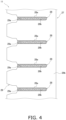
- Fig. 4 is a schematic view showing a state in which fins 29, as will be described later, are attached to the flat tubes 28 in the heat exchange portion 27.
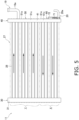
- Fig. 5 is a schematic explanatory view showing how the refrigerant flows in the outdoor heat exchanger 11. The arrows of the heat exchange portion 27 shown in Fig. 5 indicate the flow of the refrigerant during the heating operation (when the outdoor heat exchanger 11 functions as an evaporator of the refrigerant).
- the direction in which a plurality of flat tubes 28 are arranged, the longitudinal direction of a first header 40, the longitudinal direction of a gas header 50, and the longitudinal direction of a liquid header 60 are in the up-down direction or, more specifically, in the vertical direction (an example of "first direction").
- the direction in which the connection part of the flat tubes 28 to the first header 40 extends the direction in which a first gas plate part 51a and a first liquid plate part 61a of a first member 41, a second member 42, a third member 43, a fourth member 44, a fifth member 45, a sixth member 46, and a seventh member 47 are stacked, and the plate thickness direction of the first gas plate part 51a, the first liquid plate part 61a, the second member 42, the third member 43, the fourth member 44, the fifth member 45, the sixth member 46, and the seventh member 47 are in the left-right direction (an example of "second direction”).
- a direction perpendicular to both the up-down direction and the left-right direction is described as a front-rear direction (an example of "third direction").
- the outdoor heat exchanger 11 is a device that performs heat exchange between the refrigerant flowing inside and the air.
- the outdoor heat exchanger 11 mainly has the plurality of flat tubes 28, a plurality of fins 29, a second header 30, and the first header 40 (an example of "header").
- all of the flat tubes 28, the fins 29, the second header 30, and the first header 40 are made of aluminum or an aluminum alloy.
- the plurality of flat tubes 28 and the plurality of fins 29 form the heat exchange portion 27.
- air passes through ventilation passages formed between the plurality of flat tubes 28 and the plurality of fins 29.
- heat is exchanged between the refrigerant and the air.
- the flat tubes 28 are flat heat transfer tubes having upper and lower flat surfaces 28a serving as heat transfer surfaces.
- a plurality of refrigerant passages 28b are formed, extending along the direction in which the flat tubes 28 extend and through which the refrigerant flows.
- the flat tubes 28 are flat multi-hole tubes in which a large number of refrigerant passages 28b are formed.
- the plurality of refrigerant passages 28b are aligned in the air flow direction.
- the flat tubes 28 extending in the horizontal direction so as to connect the second header 30 and the first header 40 are vertically arranged in a plurality of tiers.
- the plurality of flat tubes 28 are arranged at regular intervals vertically. Note that each flat tube 28 is disposed with the flat surfaces facing up and down.
- each flat tube 28 has one bent portion in a plan view, and is formed in a substantially L-shape.
- the outdoor heat exchanger 11 has a first flow path group X and a second flow path group Y arranged in the up-down direction.
- the plurality of flat tubes 28 belong to either the first flow path group X or the second flow path group Y.
- the first flow path group X is a flow path group positioned below, and has a plurality of flat tubes 28 belonging thereto.
- the second flow path group Y is a flow path group positioned above the first flow path group X, and has a plurality of flat tubes 28 belonging thereto.
- the plurality of fins 29 are members for increasing the heat transfer area of the outdoor heat exchanger 11.
- Each of the fins 29 is a plate-shaped member extending in the up-down direction in which the plurality of flat tubes 28 are arranged, and in the flow direction of the air passing through the outdoor heat exchanger 11.
- each of the fins 29 has a plurality of cutouts 29a formed therein extending along the insertion direction of the flat tubes 28 so that the plurality of flat tubes 28 can be inserted.
- the cutouts 29a extend in a direction orthogonal to both the up-down direction and the thickness direction of the fin 29.
- the cutouts 29a formed in each fin 29 extend horizontally.
- the cutouts 29a are formed in the fin 29 at intervals corresponding to the arrangement intervals of the flat tubes 28.
- the plurality of fins 29 are arranged side by side along the direction in which the flat tubes 28 extend.
- Each fin 29 has a communication portion 29b communicating in the up-down direction on the upstream side or the downstream side in the air flow direction with respect to the flat tubes 28.
- the communicating portion 29b of the fin 29 is positioned on the windward side with respect to the flat tubes 28.
- the first header 40 includes a gas header 50 positioned in the upper portion and a liquid header 60 (an example of "header”) positioned in the lower portion.
- the gas header 50 contains a gas space 50S whose longitudinal direction is in the up-down direction.
- the liquid header 60 contains a liquid space 60S whose longitudinal direction is in the up-down direction, as a space isolated from the gas space 50S.
- the gas space 50S of the gas header 50 and the liquid space 60S of the liquid header 60 are partitioned from each other due to the shape of openings formed in stacked members that does not allow communication between the gas side and the liquid side.
- a gas refrigerant connection pipe 19a constituting one end of the first gas refrigerant pipe 19 is connected to the gas header 50.
- the gas refrigerant connection pipe 19a is connected to the right-side part of the gas header 50 opposite to the left side to which the flat tubes 28 are connected in the left-right direction.
- a liquid refrigerant connection pipe 20a constituting one end of the liquid refrigerant pipe 20 is connected to the liquid header 60.
- the liquid refrigerant connection pipe 20a is connected to the right-side part of the liquid header 60 opposite to the left side to which the flat tubes 28 are connected in the left-right direction.
- each flat tube 28 is connected to the gas header 50 and the liquid header 60 of the first header 40, and the other end of each flat tube 28 is connected to the second header 30.
- the outdoor heat exchanger 11 is disposed inside a casing, not shown, of the outdoor unit 2 in a posture such that the longitudinal direction of the first header 40 and the second header 30 substantially coincides with the vertical direction.
- the number of the flat tubes 28 connected to the gas header 50 is larger than the number of the flat tubes 28 connected to the liquid header 60.
- Each of the flat tubes 28 connected to the gas header 50 communicates with the gas space 50S.
- Each of the flat tubes 28 connected to the liquid header 60 communicates with the liquid space 60S.
- the first header 40 includes the first member 41 (an example of "plate member"), the second member 42 (an example of “plate member”), the third member 43 (an example of “plate member”), the fourth member 44 (an example of "plate member"), the fifth member 45 (an example of "plate member"), the sixth member 46 (an example of "plate member", an example of "first plate member”, an example of “plate-shaped member”), and the seventh member 47 (an example of "plate member”).
- the first member 41, the second member 42, the third member 43, the fourth member 44, the fifth member 45, the sixth member 46, and the seventh member 47 extend in the up-down direction over the gas header 50 and the liquid header 60.
- first member 41, the second member 42, the third member 43, the fourth member 44, the fifth member 45, the sixth member 46, and the seventh member 47 each include a part constituting a part of the gas header 50 and another part constituting a part of the liquid header 60, and are shared by the gas header 50 and the liquid header 60.
- Each of the first member 41, the second member 42, the third member 43, the fourth member 44, the fifth member 45, the sixth member 46, and the seventh member 47 has a longitudinal direction in the up-down direction, and has the same length in the up-down direction.
- the lengths in the front-rear direction of the first gas plate part 51a and the first liquid plate part 61a of the first member 41 except for the first gas side plate part 51c, the first liquid side plate part 61c, the second gas side plate part 51d, and the second liquid side plate part 61d are the same as the lengths of the second member 42, the third member 43, the fourth member 44, the fifth member 45, the sixth member 46, and the seventh member 47.
- the first gas side plate part 51c and the first liquid side plate part 61c have the same length in the left-right direction, which is the direction in which the flat tubes 28 extend.
- the second gas side plate part 51d and the second liquid side plate part 61d have the same length in the left-right direction, which is the direction in which the flat tubes 28 extend.
- the fourth member 44, the fifth member 45, the sixth member 46, and the seventh member 47 of the first header 40 form the gas space 50S of the gas header 50 and the liquid space 60S of the liquid header 60.
- the first member 41 has a first gas-side portion 51 and a first liquid-side portion 61.
- the second member 42 has a second gas-side portion 52 and a second liquid-side portion 62.
- the third member 43 has a third gas-side portion 53 and a third liquid-side portion 63.
- the fourth member 44 has a fourth gas-side portion 54 and a fourth liquid-side portion 64.
- the fifth member 45 has a fifth gas-side portion 55 and a fifth liquid-side portion 65.
- the sixth member 46 has a sixth gas-side portion 56 and a sixth liquid-side portion 66.
- the seventh member 47 has a seventh gas-side portion 57 and a seventh liquid-side portion 67.
- each flat tube 28 on the opposite side from the end connected to the first header 40 is connected to the second header 30.
- the second header 30 is configured by surrounding and crimping a plurality of stacked plate-shaped members with a crimping member 31 having a U-shape in plan view to which the flat tubes 28 are connected.
- the control unit 3 receives detection information from various sensors or a command from a remote controller or the like, and switches and executes a cooling operation, a heating operation, a defrosting operation, and the like.
- the control unit 3 switches the connection state of the four-way switching valve 10 to the state indicated by the broken lines in Fig. 1 and then operates the compressor 8.
- the refrigerant discharged from the compressor 8 dissipates heat or condenses by exchanging heat with the indoor air in the indoor heat exchanger 91, is decompressed in the indoor expansion valve 93 or the outdoor expansion valve 12, and is then sent to the outdoor heat exchanger 11.
- the refrigerant sent to the outdoor heat exchanger 11 is evaporated by exchanging heat with the outside air, and is sucked into the compressor 8 again.
- the refrigerant in a liquid state or a gas-liquid two-phase state that has reached the liquid header 60 from the liquid refrigerant pipe 20 is split in the internal space of the liquid header 60 and then sent to the flat tubes 28 belonging to the first flow path group X.
- the refrigerant flowing through the flat tubes 28 of the first flow path group X partly evaporates by exchanging heat with the air, and reaches the lower region of the internal space of the second header 30.
- the refrigerant sent to the lower region of the internal space of the second header 30 is sent to the upper region of the internal space of the second header 30.
- the refrigerant sent to the upper region of the second header 30 flows through the plurality of flat tubes 28 belonging to the second flow path group Y connected to the upper region of the second header 30.
- the refrigerant flowing through the plurality of flat tubes 28 belonging to the second flow path group Y further evaporates by exchanging heat with the air again, and reaches the gas header 50.
- the flows of the refrigerant that have reached the gas header 50 merge and the the refrigerant then flows through the first gas refrigerant pipe 19.
- the control unit 3 switches the connection state of the four-way switching valve 10 to the state indicated by the solid lines in Fig. 1 and then operates the compressor 8.
- the refrigerant discharged from the compressor 8 dissipates heat or condenses by exchanging heat with the outside air in the outdoor heat exchanger 11, is decompressed in the outdoor expansion valve 12 or the indoor expansion valve 93, and is then sent to the indoor heat exchanger 91.
- the refrigerant sent to the indoor heat exchanger 91 evaporates by exchanging heat with the indoor air, and is sucked into the compressor 8 again.
- the control unit 3 switches the connection state of the four-way switching valve 10 to the state indicated by the solid lines in Fig. 1 and operates the compressor 8 to perform a defrosting operation in which a high-temperature and high-pressure discharged refrigerant is supplied to the outdoor heat exchanger 11.
- the defrosting operation melts frost deposited on the outdoor heat exchanger 11.
- the outdoor heat exchanger 11 functions as a radiator or a condenser of the refrigerant during the cooling operation or the defrosting operation
- the refrigerant discharged from the compressor 8 flows into the gas header 50 after flowing through the first gas refrigerant pipe 19.
- the gaseous refrigerant that has reached the gas header 50 is split in the internal space of the gas header 50, and then flows through the plurality of flat tubes 28 belonging to the second flow path group Y connected to the gas header 50.
- the refrigerant flowing through the plurality of flat tubes 28 belonging to the second flow path group Y partially dissipates heat or condenses by exchanging heat with the air, and reaches the upper region of the internal space of the second header 30.
- the refrigerant sent to the upper region of the internal space of the second header 30 is sent to the lower region of the second header 30.
- the refrigerant sent to the lower region of the second header 30 is sent to the plurality of flat tubes 28 belonging to the first flow path group X connected to the lower region of the second header 30.
- the refrigerant flowing through the plurality of flat tubes 28 of the first flow path group X further dissipates heat or condenses by exchanging heat with the air again, and reaches the liquid header 60.
- the refrigerant that has reached the liquid header 60 flows out from the outdoor heat exchanger 11 via the liquid refrigerant pipe 20.
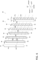
- Fig. 6 is a schematic exploded perspective view of the gas header 50.
- Fig. 7 is a schematic horizontal cross-sectional configuration diagram of the gas header 50. Fig. 7 illustrates a horizontal cross section obtained when the flat tube 28 positioned at the lowermost tier among the plurality of flat tubes 28 connected to the gas header 50 is cut horizontally at the center position in the thickness direction (up-down direction).
- the gas header 50 is configured to include the first gas-side portion 51 of the first member 41, the second gas-side portion 52 of the second member 42, the third gas-side portion 53 of the third member 43, the fourth gas-side portion 54 of the fourth member 44, the fifth gas-side portion 55 of the fifth member 45, the sixth gas-side portion 56 of the sixth member 46, and the seventh gas-side portion 57 of the seventh member 47.
- the fourth gas-side portion 54, the fifth gas-side portion 55, the sixth gas-side portion 56, and the seventh gas-side portion 57 form the gas space 50S.
- the first gas-side portion 51, the second gas-side portion 52, the third gas-side portion 53, the fourth gas-side portion 54, the fifth gas-side portion 55, the sixth gas-side portion 56, and the seventh gas-side portion 57 are joined to each other by brazing.
- the first gas-side portion 51 constitutes a part of the gas header 50 and includes the first gas side plate part 51a, the first gas side plate part 51c, the second gas side plate part 51d, first gas crimping claws 51e, and second gas crimping claws 51f.
- the first gas-side portion 51 mainly constitutes the periphery of the outer shape of the gas header 50 together with the seventh gas-side portion 57.
- the first gas plate part 51a is stacked so as to face and be in contact with the left-side surface of the second gas plate part 52a of the second gas-side portion 52.
- the first gas plate part 51a has a plurality of gas-side flat tube connection openings 51b.
- the plurality of gas-side flat tube connection openings 51b are openings aligned in the up-down direction and penetrating the first gas plate part 51a in the plate thickness direction.
- the contour of the gas-side flat tube connection openings 51b has a shape that follows the contour of the flat tubes 28.
- the flat tubes 28 are brazed to the gas-side flat tube connection openings 51b in a state where the tip-ends of the flat tubes 28 in the insertion direction have passed through the gas-side flat tube connection openings 51b, and where the outer peripheries of the flat tubes 28 are in contact with the inner peripheries of the gas-side flat tube connection openings 51b.
- the first gas side plate part 51c is a plate-shaped part extending rightward from the front-side edge of the first gas plate part 51a.
- the second gas side plate part 51d is a plate-shaped part extending rightward from the rear-side edge of the first gas side plate part 51a.
- the first gas side plate part 51c and the second gas side plate part 51d are provided to face each other in the front-rear direction, thereby sandwiching the second gas plate part 52a, the third gas plate part 53a, the fourth gas plate part 54a, the fifth gas plate part 55a, the sixth gas plate part 56a, and the seventh gas plate part 57a from the front-rear directions.
- the first gas crimping claws 51e are a plurality of crimping claws provided at a predetermined interval in the up-down direction at the right-side end part of the first gas side plate part 51c.
- the second gas crimping claws 51f are a plurality of crimping claws provided at a predetermined interval in the up-down direction at the right-side end part of the second gas side plate part 51d.
- the first gas crimping claws 51e extend rightward on an extension of the first gas side plate part 51c
- the second gas crimping claws 51f extend rightward on an extension of the second gas side plate part 51d.
- the first gas crimping claws 51e and the second gas crimping claws 51f are folded so as to approach each other in the front-rear direction, whereby the first gas plate part 51a, the second gas plate part 52a, the third gas plate part 53a, the fourth gas plate part 54a, the fifth gas plate part 55a, the sixth gas plate part 56a, and the seventh gas plate part 57a are crimped and integrated.
- brazing is performed in a furnace or the like, whereby the members are joined and completely fixed together by brazing.
- the second gas-side portion 52 constitutes a part of the gas header 50 and has the second gas plate part 52a.
- the second gas plate part 52a is stacked so as to face and be in contact with the right-side surface of the first gas plate part 51a, and so as to face and be in contact with the left-side surface of the third gas plate part 53a.
- the second gas plate part 52a has a plurality of gas insertion openings 52b.
- the plurality of gas insertion openings 52b are openings aligned in the up-down direction and penetrating the second gas plate part 52a in the plate thickness direction.
- the front and rear edges of the gas insertion openings 52b are positioned outside the front and rear edges of the gas-side flat tube connection openings 51b when viewed in the plate thickness direction of the second gas plate part 52a.
- the upper and lower edges of the plurality of gas insertion openings 52b are positioned outside the upper and lower edges of the gas-side flat tube connection openings 51b when viewed in the plate thickness direction of the second gas plate part 52a.
- the contour of the gas insertion openings 52b does not overlap the contour of the flat tubes 28, and is positioned outside the contour of the flat tubes 28.
- the tip-ends of the flat tubes 28 in the insertion direction are inserted so as to pass through the gas insertion openings 52b.
- a clearance is secured between the flat tubes 28 and the gas insertion openings 52b so that the excess brazing material can be guided. Therefore, the flow path of the flat tubes 28 can be prevented from being blocked by the excess brazing material.
- the third gas-side portion 53 constitutes a part of the gas header 50 and has the third gas plate part 53a.
- the third gas plate part 53a is stacked so as to face and be in contact with the right-side surface of the second gas plate part 52a, and so as to face and be in contact with the left-side surface of the fourth gas plate part 54a.
- the third gas plate part 53a has a plurality of gas restriction openings 53b.
- the plurality of gas restriction openings 53b are openings aligned in the up-down direction and penetrating the third gas plate part 53a in the plate thickness direction.
- the front and rear edges of the gas restriction openings 53b are positioned inside the front and rear edges of the gas insertion openings 52b when viewed in the plate thickness direction of the third gas plate part 53a.
- the width of the plurality of gas restriction openings 53b in the front-rear direction is narrower than the width of the flat tubes 28 in the front-rear direction. As a result, the tip-ends of the flat tubes 28 in the insertion direction abut the edges of the gas restriction openings 53b, whereby the insertion position is determined.
- the upper and lower edges of the plurality of gas restriction openings 53b are positioned outside the front and rear edges of the flat tubes 28.
- the refrigerant that has flowed into the gas space 50S formed by the third gas plate part 53a, the fourth gas plate part 54a, the fifth gas plate part 55a, the sixth gas plate part 56a, and the seventh gas plate part 57a via the gas refrigerant connection pipe 19a is branched and flows to the plurality of gas restriction openings 53b.
- the fourth gas-side portion 54 constitutes a part of the gas header 50 and has the fourth gas plate part 54a.
- the fourth gas plate part 54a is stacked so as to face and be in contact with the right-side surface of the third gas plate part 53a, and so as to face and be in contact with the left-side surface of the fifth gas plate part 55a.
- the fourth gas plate part 54a has a fourth gas opening 54b.
- the fourth gas opening part 54b is an opening penetrating the fourth gas plate part 54a in the plate thickness direction, and is an opening whose longitudinal direction is in the up-down direction.
- the fourth gas opening 54b overlaps the connection area of the plurality of flat tubes 28 in the gas header 50, and, for example, overlaps the connection area of three or more or five or more flat tubes 28.
- the width of the fourth gas opening 54b in the front-rear direction corresponds to the width of the gas restriction openings 53b of the third member 43 in the front-rear direction.
- the fifth gas-side portion 55 constitutes a part of the gas header 50 and has the fifth gas plate part 55a.
- the fifth gas plate part 55a is stacked so as to face and be in contact with the right-side surface of the fourth gas plate part 54a, and so as to face and be in contact with the left-side surface of the sixth gas plate part 56a.
- the fifth gas plate part 55a has a fifth gas opening part 55b.
- the fifth gas opening part 55b is an opening penetrating the fifth gas plate part 55a in the plate thickness direction, and is an opening whose longitudinal direction is in the up-down direction. When viewed in the plate thickness direction of the fifth gas plate part 55a, the fifth gas opening part 55b overlaps the connection area of the plurality of flat tubes 28 in the gas header 50.
- the sixth gas-side portion 56 constitutes a part of the gas header 50 and has the sixth gas plate part 56a.
- the sixth gas plate part 56a is stacked so as to face and be in contact with the right-side surface of the fifth gas plate part 55a, and so as to face and be in contact with the left-side surface of the seventh gas plate part 57a.
- the sixth gas plate part 56a has a sixth gas opening part 56b (an example of "second opening part").
- the sixth gas opening part 56b is an opening penetrating the sixth gas plate part 56a in the plate thickness direction, and is an opening whose longitudinal direction is in the up-down direction. When viewed in the plate thickness direction of the sixth gas plate part 56a, the sixth gas opening part 56b overlaps the connection area of the plurality of flat tubes 28 in the gas header 50.
- the seventh gas-side portion 57 constitutes a part of the gas header 50 and has the seventh gas plate part 57a.
- the seventh gas plate part 57a is stacked so as to face and be in contact with the right-side surface of the sixth gas plate part 56a.
- the seventh gas plate part 57a has a gas pipe connection opening 57b which is an opening penetrating the seventh gas plate part 57a in the plate thickness direction and to which the gas refrigerant connection pipe 19a is connected.
- the seventh gas plate part 57a is a plate-shaped member which has a surface extending so as to overlap the sixth gas opening part 56b when viewed in the plate thickness direction of the seventh gas plate part 57a, and which constitutes an outer wall portion of the gas header 50 so as to close the gas space 50S from the right side.
- the front-side part of the seventh gas plate part 57a is crimped by the first gas crimping claws 51e of the first member 41.
- the rear-side part of the seventh gas plate part 57a is crimped by the second gas crimping claws 51f.
- Fig. 8 is a schematic exploded perspective view of the liquid header 60 (corresponding to "header").
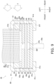
- Fig. 9 is a schematic horizontal cross-sectional configuration diagram of the liquid header 60. Note that Fig. 9 shows a horizontal cross-section obtained when, of the flat tubes 28 connected to the liquid header 60, the flat tube 28 at the same height position as a second blow-up region 64j is cut horizontally at the center position in the thickness direction (up-down direction). In Fig. 9 , the first connection pipe 71 and the second connection pipe 72 are not shown.
- Fig. 10 shows a partially enlarged view of the vicinity of the lower end of the sixth liquid-side portion 66 in the liquid header 60.
- Fig. 11 is a diagram illustrating how the refrigerant flows in the liquid header 60 when the outdoor heat exchanger 11 functions as an evaporator of the refrigerant.
- the liquid header 60 is configured to include a first liquid-side portion 61 of the first member 41, a second liquid-side portion 62 of the second member 42, a third liquid-side portion 63 of the third member 43, a fourth liquid-side portion 64 of the fourth member 44, a fifth liquid-side portion 65 of the fifth member 45, a sixth liquid-side portion 66 of the sixth member 46, a seventh liquid-side portion 67 of the seventh member 47, the first connection pipe 71, and the second connection pipe 72.
- the fourth liquid-side portion 64, the fifth liquid-side portion 65, the sixth liquid-side portion 66, and the seventh liquid-side portion 67 form the liquid space 60S of the liquid header 60.
- the liquid header 60 is formed by joining the first liquid-side portion 61, the second liquid-side portion 62, the third liquid-side portion 63, the fourth liquid-side portion 64, the fifth liquid-side portion 65, the sixth liquid-side portion 66, and the seventh liquid-side portion 67 to each other by brazing.
- the liquid refrigerant connection pipe 20a is connected to the liquid header 60.
- the refrigerant flowing in via the liquid refrigerant connection pipe 20a is split inside the liquid header 60, and the split flows of the refrigerant are sent to the plurality of flat tubes 28 included in the first flow path group X among the plurality of flat tubes 28.
- the first liquid-side portion 61 constitutes a part of the liquid header 60 and includes the first liquid plate part 61a, the first liquid side plate part 61c, the second liquid side plate part 61d, first liquid crimping claws 61e, and second liquid crimping claws 61f.
- the first liquid-side portion 61 mainly constitutes the periphery of the outer shape of the liquid header 60 together with the seventh liquid-side portion 67.
- the first liquid plate part 61a is provided so as to be continuous with the first gas plate part 51a on the same plane.
- the first liquid side plate part 61c is provided so as to be continuous with the first gas side plate part 51c on the same plane.
- the second liquid side plate part 61d is provided so as to be continuous with the second gas side plate part 51d on the same plane.
- the first liquid plate part 61a is stacked so as to face and be in contact with the left-side surface of a second liquid plate part 62a of the second liquid-side portion 62.
- the first liquid plate part 61a has a plurality of liquid-side flat tube connection openings 61b.
- the plurality of liquid-side flat tube connection openings 61b are openings aligned in the up-down direction, and penetrating the first liquid plate part 61a in the plate thickness direction.
- the contour of the liquid-side flat tube connection openings 61b has a shape that follows the contour of the flat tubes 28.
- the flat tubes 28 are brazed to each other in a state where the tip-ends thereof in the insertion direction have passed through the liquid-side flat tube connection openings 61b and the outer peripheries of the flat tubes 28 are in contact with the inner peripheries of the liquid-side flat tube connection openings 61b.
- the first liquid side plate part 61c is a plate-shaped part extending rightward from the front-side edge of the first liquid plate part 61a.
- the second liquid side plate part 61d is a plate-shaped part extending rightward from the rear-side edge of the first liquid plate part 61a.
- the first liquid side plate part 61c and the second liquid side plate part 61d are provided so as to face each other in the front-rear direction, thereby sandwiching the second liquid plate part 62a, the third liquid plate part 63a, the fourth liquid plate part 64a, the fifth liquid plate part 65a, the sixth liquid plate part 66a, and the seventh liquid plate part 67a from the front-rear directions.
- the first liquid crimping claws 61e are a plurality of crimping claws provided at a predetermined interval in the up-down direction at the right-side end part of the first liquid side plate part 61c.
- the second liquid crimping claws 61f are a plurality of crimping claws provided at a predetermined interval in the up-down direction at the right-side end part of the second liquid side plate part 61d.
- the first liquid crimping claws 61e and the second liquid crimping claw 61f are folded so as to approach each other in the front-rear direction, whereby the second liquid plate part 62a, the third liquid plate part 63a, the fourth liquid plate part 64a, the fifth liquid plate part 65a, the sixth liquid plate part 66a, and the seventh liquid plate part 67a are crimped and integrated together.
- brazing is performed in a furnace or the like, whereby the members are joined and completely fixed together by brazing.
- the second liquid-side portion 62 constitutes a part of the liquid header 60 and is provided between the third liquid-side portion 63 and the first liquid-side portion 61.
- the second liquid-side portion 62 has the second liquid plate part 62a and a plurality of liquid insertion openings 62b.
- the second liquid plate part 62a is stacked so as to face and be in contact with the right-side surface of the first liquid plate part 61a, and so as to face and be in contact with the left-side surface of the third liquid plate part 63a.
- the plurality of liquid insertion openings 62b are openings aligned in the up-down direction and penetrating the second liquid plate part 62a in the plate thickness direction.
- the front and rear edges of the liquid insertion openings 62b are positioned outside the front and rear edges of the liquid-side flat tube connection openings 61b when viewed in the plate thickness direction of the second liquid plate part 62a.
- the upper and lower edges of the plurality of liquid insertion openings 62b are positioned outside the upper and lower edges of the liquid-side flat tube connection openings 61b when viewed in the plate thickness direction of the second liquid plate part 62a.
- the contour of the liquid insertion openings 62b does not overlap the contour of the flat tubes 28, and is positioned outside the contour of the flat tubes 28.
- the tip-ends of the flat tubes 28 in the insertion direction are inserted so as to pass through the liquid insertion openings 62b.
- a clearance is secured between the flat tubes 28 and the liquid insertion openings 62b so that the excess brazing material can be guided. Therefore, the flow path of the flat tubes 28 is prevented from being blocked by the excess brazing material.
- the third liquid-side portion 63 constitutes a part of the liquid header 60 and is provided between the fourth liquid-side portion 64 and the second liquid-side portion 62.
- the third liquid-side portion 63 has the third liquid plate part 63a and a plurality of liquid restriction openings 63b.
- the third liquid plate part 63a is a plate-shaped member having a plate thickness direction in the left-right direction and extending in the up-down and front-rear directions.
- the third liquid plate part 63a is stacked so as to face and be in contact with the left-side surface of the fourth liquid plate part 64a, and so as to face and be in contact with the right-side surface of the second liquid plate part 62a.
- the plurality of liquid restriction openings 63b are openings aligned in the up-down direction and penetrating the third liquid plate part 63a in the plate thickness direction.
- the front and rear edges of the liquid restriction openings 63b are positioned inside the front and rear edges of the liquid insertion openings 62b when viewed in the plate thickness direction of the third liquid plate part 63a.
- the width of the plurality of liquid restriction openings 63b in the front-rear direction is narrower than the width of the flat tubes 28 in the front-rear direction. As a result, the tip-ends of the flat tubes 28 in the insertion direction abut the edges of the liquid restriction openings 63b, whereby the insertion position is determined.
- the upper and lower edges of the plurality of liquid restriction openings 63b are positioned outside the front and rear edges of the flat tubes 28.
- those positioned above the two at the lower end are such that a plurality of lower liquid restriction openings 63b overlap and communicate with a first blow-up region 64f of a first through part 64c of the fourth liquid-side portion 64, and such that a plurality of upper liquid restriction openings 63b overlap and communicate with the second blow-up region 64j of a second through part 64g of the fourth liquid-side portion 64.
- the fourth liquid-side portion 64 constitutes a part of the liquid header 60 and is provided between the fifth liquid-side portion 65 and the third liquid-side portion 63.
- the fourth liquid-side portion 64 has the fourth liquid plate part 64a, the opening 64b, the first through part 64c, and the second through part 64g.
- the fourth liquid plate part 64a is a plate-shaped member having a plate thickness direction in the left-right direction and extending in the up-down and front-rear directions.
- the fourth liquid plate part 64a is stacked so as to face and be in contact with the left-side surface of the fifth liquid plate part 65a, and so as to face and be in contact with the right-side surface of the third liquid plate part 63a.
- the first through part 64c is an opening that is provided above the opening 64b in the fourth liquid-side portion 64 and below the second through part 64g, and that penetrates the fourth liquid plate part 64a in the plate thickness direction.
- the first through part 64c has a first introduction region 64d, a first narrowed region 64e, and the first blow-up region 64f.
- the first introduction region 64d, the first narrowed region 64e, and the first blow-up region 64f are arranged in this order from bottom to top at the center in the front-rear direction, and are connected to each other.
- the length of the first narrowing region 64e in the front-rear direction is smaller than the length of the first introduction region 64d in the front-rear direction and smaller than the length of the first blow-up region 64f in the front-rear direction.
- the first introduction region 64d overlaps and communicates with a first communication opening 65b of the fifth liquid-side portion 65 when viewed in the plate thickness direction of the fourth liquid plate part 64a.
- the first narrowed region 64e is covered from the right side by the fifth liquid plate part 65a of the fifth liquid-side portion 65.
- the first blow-up region 64f communicates with a plurality of liquid restriction openings 63b arranged vertically on the left side.
- the first blow-up region 64f communicates with a first outgoing opening 65d of the fifth liquid-side portion 65 positioned on the right side at the upper end, and communicates with a first return opening 65c of the fifth liquid-side portion 65 positioned on the right side at the lower end.
- the area below the part communicating with the first outgoing opening 65d and above the part communicating with the first return opening 65c is covered by the fifth liquid plate part 65a of the fifth liquid-side portion 65 from the right side.
- the second through part 64g is an opening that is provided above the first through part 64c in the fourth liquid-side portion 64 and that penetrates the fourth liquid plate part 64a in the plate thickness direction.
- the second through part 64g has a second introduction region 64h, a second narrowed region 64i, and the second blow-up region 64j.
- the second introduction region 64h, the second narrowed region 64i, and the second blow-up region 64j are arranged from bottom to top in this order at the center in the front-rear direction, and are connected to each other.
- the width of the second narrowed region 64i in the front-rear direction is smaller than the width of the second introduction region 64h in the front-rear direction and smaller than the width of the second blow-up region 64j in the front-rear direction.
- the second introduction region 64h overlaps and communicates with a second communication opening 65e of the fifth liquid-side portion 65 when viewed in the plate thickness direction of the fourth liquid plate part 64a.
- the second narrowed region 64i is covered from the right side by the fifth liquid plate part 65a of the fifth liquid-side portion 65.
- the second blow-up region 64j communicates with a plurality of liquid restriction openings 63b arranged vertically on the left side.
- the second blow-up region 64j communicates with a second outgoing opening 65g of the fifth liquid-side portion 65 positioned on the right side at the upper end, and communicates with a second return opening 65f of the fifth liquid-side portion 65 positioned on the right side at the lower end.
- the area below the part communicating with the second outgoing opening 65g and above the portion communicating with the second return opening 65f is covered by the fifth liquid plate part 65a of the fifth liquid-side portion 65 from the right side.
- the fifth liquid-side portion 65 constitutes a part of the liquid header 60 and is provided between the sixth liquid-side portion 66 and the fourth liquid-side portion 64.
- the fifth liquid-side portion 65 includes the fifth liquid plate part 65a, the first communication opening 65b, the first return opening 65c, the first outgoing opening 65d, the second communication opening 65e, the second return opening 65f, and the second outgoing opening 65g.
- the fifth liquid plate part 65a is a plate-shaped member having a plate thickness direction in the left-right direction and extending in the up-down and front-rear directions.
- the fifth liquid plate part 65a is stacked so as to face and be in contact with the left-side surface of the sixth liquid plate part 66a, and so as to face and be in contact with the right-side surface of the fourth liquid plate part 64a.
- All of the first communication opening 65b, the first return opening 65c, the first outgoing opening 65d, the second communication opening 65e, the second return opening 65f, and the second outgoing opening 65g are openings penetrating the fifth liquid plate part 65a in the plate thickness direction, and are arranged in this order from the bottom.
- the first communication opening 65b communicates with the first introduction region 64d of the fourth liquid-side portion 64 on the left side, and communicates with the first communication opening 66c of the sixth liquid-side portion 66 on the right side.
- the first return opening 65c communicates with the lower-end part of the first blow-up region 64f of the fourth liquid-side portion 64 on the left side, and communicates with the lower-end part of a first descending opening 66d of the sixth liquid-side portion 66 on the right side.
- the first outgoing opening 65d communicates with the upper-end part of the first blow-up region 64f of the fourth liquid-side portion 64 on the left side, and communicates with the upper-end part of the first descending opening 66d of the sixth liquid-side portion 66 on the right side.
- the second communication opening 65e communicates with the second introduction region 64h of the fourth liquid-side portion 64 on the left side, and communicates with a second communication opening 66e of the sixth liquid-side portion 66 on the right side.
- the second return opening 65f communicates with the lower-end part of the second blow-up region 64j of the fourth liquid-side portion 64 on the left side, and communicates with the lower-end part of a second descending opening 66f of the sixth liquid-side portion 66 on the right side.
- the second outgoing opening 65g communicates with the upper-end part of the second blow-up region 64j of the fourth liquid-side portion 64 on the left side, and communicates with the upper-end part of the second descending opening 66f of the sixth liquid-side portion 66 on the right side.
- the sixth liquid-side portion 66 constitutes a part of the liquid header 60 and is provided between the seventh liquid-side portion 67 and the fifth liquid-side portion 65.
- the sixth liquid-side portion 66 has the sixth liquid plate part 66a, a first opening part 66b, a first communication opening 66c (an example of "second opening part"), the first descending opening 66d (an example of "second opening part”), the second communication opening 66e (an example of "second opening part”), and the second descending opening 66f (an example of "second opening part”).
- the sixth liquid plate part 66a is a plate-shaped member having a plate thickness direction in the left-right direction and extending in the up-down and front-rear directions.
- the sixth liquid plate part 66a is stacked so as to face and be in contact with the left-side surface of the seventh liquid plate part 67a, and so as to face and be in contact with the right-side surface of the fifth liquid plate part 65a.
- All of the first opening part 66b, the first communication opening 66c, the first descending opening 66d, the second communication opening 66e, and the second descending opening 66f are openings penetrating the sixth liquid plate part 66a in the plate thickness direction, and are arranged in this order from the bottom.
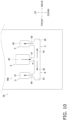
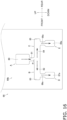
- the first opening part 66b is covered with the fifth liquid plate part 65a of the fifth liquid-side portion 65 on the left side, and communicates with a liquid pipe connection opening 67b, a first distribution opening 67c, and a second distribution opening 67d of the seventh liquid-side portion 67 on the right side. While the details will be described later, when the outdoor heat exchanger 11 functions as an evaporator of the refrigerant, the first opening part 66b causes the refrigerant flowing in from the liquid pipe connection opening 67b to be divided and flow to the first distribution opening 67c and the second distribution opening 67d.
- the first communication opening 66c communicates with the first communication opening 65b of the fifth liquid-side portion 65 on the left side, and communicates with the first communication opening 67e of the seventh liquid-side portion 67 on the right side.
- the first descending opening 66d communicates with the first return opening 65c of the fifth liquid-side portion 65 at the lower end on the left side, communicates with the first outgoing opening 65d of the fifth liquid-side portion 65 at the upper end on the left side, and is covered by the seventh liquid plate part 67a of the seventh liquid-side portion 67 on the right side.
- the second communication opening 66e communicates with the second communication opening 65e of the fifth liquid-side portion 65 on the left side, and communicates with the second communication opening 67f of the seventh liquid-side portion 67 on the right side.
- the second descending opening 66f communicates with the second return opening 65f of the fifth liquid-side portion 65 at the lower end on the left side, communicates with the second outgoing opening 65g of the fifth liquid-side portion 65 at the upper end on the left side, and is covered by the seventh liquid plate part 67a of the seventh liquid-side portion 67 on the right side.
- the refrigerant introduced into the first introduction region 64d via a flow path (an example of "sixth flow path") configured by the first communication opening 67e, the first communication opening 66c, the first communication opening 65b, and the first introduction region 64d is blown up from the first narrowed region 64e toward the first blow-up region 64f.
- the refrigerant blown up to the first blow-up region 64f is split to the plurality of liquid restriction openings 63b at the respective height positions while flowing upward in the first blow-up region 64f, and the refrigerant that did not flow toward the plurality of liquid restriction openings 63b reaches the upper end of the first blow-up region 64f.
- the refrigerant that has reached the upper end of the first blow-up region 64f circulates by passing through the first outgoing opening 65d, descending through the first descending opening 66d, and then returning to the lower-end part of the first blow-up region 64f via the first return opening 65c.
- the outdoor heat exchanger 11 functions as an evaporator of the refrigerant
- the refrigerant introduced into the second introduction region 64h via the flow path (an example of "seventh flow path") configured by the second communication opening 67f, the second communication opening 66e, the second communication opening 65e, and the second introduction region 64h is blown up from the second narrowed region 64i toward the second blow-up region 64j.
- the refrigerant blown up to the second blow-up region 64j is split to the plurality of liquid restriction openings 63b at the respective height positions while flowing upward in the second blow-up region 64j, and the refrigerant that did not flow toward the plurality of liquid restriction openings 63b reaches the upper end of the second blow-up region 64j.
- the refrigerant that has reached the upper end of the second blow-up region 64j circulates by passing through the second outgoing opening 65g, descending through the second descending opening 66f, and then returning to the lower-end part of the second blow-up region 64j via the second return opening 65f.
- the flow path configured by the first communication opening 67e, the first communication opening 66c, the first communication opening 65b, and the first introduction region 64d, and the flow path configured by the second communication opening 67f, the second communication opening 66e, the second communication opening 65e, and the second introduction region 64h preferably have the same flow path area and the same flow path length.
- the seventh liquid-side portion 67 constitutes a part of the liquid header 60 and is provided on the right side of the sixth liquid-side portion 66.
- the seventh liquid-side portion 67 has the seventh liquid plate part 67a, the liquid pipe connection opening 67b, the first distribution opening 67c, the second distribution opening 67d, the first communication opening 67e, and the second communication opening 67f.
- the seventh liquid plate part 67a is a plate-shaped member constituting an outer wall portion on the right side of the liquid header 60 so as to close the liquid space 60S from the right side, and extends in the up-down and front-rear directions.
- the seventh liquid plate part 67a covers a part of the first opening part 66b, the first descending opening 66d, and the second descending opening 66f of the sixth liquid-side portion 66 from the right side.
- the liquid pipe connection opening 67b is a cylindrical opening penetrating the seventh liquid plate part 67a in the plate thickness direction at the center in the front-rear direction in the vicinity of the lower end of the seventh liquid-side portion 67.
- the liquid refrigerant connection pipe 20a is connected to the liquid pipe connection opening 67b.
- the first distribution opening 67c is provided on the lower front side of the liquid pipe connection opening 67b of the seventh liquid-side portion 67, and is a cylindrical opening penetrating the seventh liquid plate part 67a in the plate thickness direction.
- the first distribution opening 67c communicates with a fourth region 87 of the first opening part 66b on the left side.
- a pipe-end part 71a of the first connection pipe 71 is connected to the first distribution opening 67c on the right side.
- the second distribution opening 67d is provided on the lower rear side of the liquid pipe connection opening 67b of the seventh liquid-side portion 67, and is a cylindrical opening penetrating the seventh liquid plate part 67a in the plate thickness direction.
- the second distribution opening 67d communicates with a fifth region 89 of the first opening part 66b on the left side.
- a pipe-end part 72a of the second connection pipe 72 is connected to the second distribution opening 67d on the right side.
- the first communication opening 67e is a cylindrical opening penetrating the seventh liquid plate part 67a in the plate thickness direction at the center in the front-rear direction above the liquid pipe connection opening 67b of the seventh liquid-side portion 67.
- a pipe-end part 71b of the first connection pipe 71 is connected to the first communication opening 67e.
- the second communication opening 67f is a cylindrical opening penetrating the seventh liquid plate part 67a in the plate thickness direction at the center in the front-rear direction above the first communication opening 67e of the seventh liquid-side portion 67.
- a pipe-end part 72b of the second connection pipe 72 is connected to the second communication opening 67f.
- the front-side part of the seventh liquid plate part 67a is crimped by the first liquid crimping claws 61e.
- the rear-side part of the seventh liquid plate part 67a is crimped by the second liquid crimping claws 61f.
- the first connection pipe 71 is provided on the right side of the seventh liquid-side portion 67, has the pipe-end part 71a and the pipe-end part 71b, and extends from the pipe-end part 71a to the pipe-end part 71b.
- the first connection pipe 71 is connected to the first distribution opening 67c of the seventh liquid-side portion 67 at the pipe-end part 71a.
- the first connection pipe 71 is connected to the first communication opening 67e of the seventh liquid-side portion 67 at the pipe-end part 71b.
- the second connection pipe 72 is provided on the right side of the seventh liquid-side portion 67, has the pipe-end part 72a and the pipe-end part 72b, and extends from the pipe-end part 72a to the pipe-end part 72b.
- the second connection pipe 72 is connected to the second distribution opening 67d of the seventh liquid-side portion 67 at the pipe-end part 72a.
- the second connection pipe 72 is connected to the second communication opening 67f of the seventh liquid-side portion 67 at the pipe-end part 72b.
- the first opening part 66b includes a connecting portion P, a first region 80 (an example of "first portion"), a first narrowed portion 81, a second region 82, a first protrusion 83, a third region 84, a second protrusion 85, a fourth narrowed portion 86, a fourth region 87, a fifth narrowed portion 88, and a fifth region 89.
- the first region 80 is positioned above the center in the front-rear direction of the first opening part 66b, and extends upward and downward such that the longitudinal direction thereof is in the vertical direction.
- the left side of the first region 80 is covered by the fifth liquid plate part 65a.
- the first region 80 overlaps and communicates with the liquid pipe connection opening 67b when viewed in the plate thickness direction of the sixth liquid plate part 66a.
- the first region 80, the liquid pipe connection opening 67b, and the liquid refrigerant connection pipe 20a are aligned in the horizontal direction.
- the connection part between the first region 80 and the liquid pipe connection opening 67b is preferably located at a position offset above the center of the first region 80 in the up-down direction.
- the first narrowed portion 81 is positioned below the first region 80 and above the connecting portion P, and is connected to the first region 80 and the connecting portion P.
- the center in the front-rear direction of the first narrowed portion 81, the center in the front-rear direction of the first region 80, and the connecting portion P are aligned in the vertical direction.
- the horizontal cross-sectional area, which is the flow path cross-sectional area, of the first narrowed portion 81 is smaller than the horizontal cross-sectional area, which is the flow path cross-sectional area, of the first region 80, and is equal to or less than half of the horizontal cross-sectional area, which is the flow path cross-sectional area, of the first region 80.
- the left side of the first narrowed portion 81 is covered by the fifth liquid plate part 65a, and the right side thereof is covered by the seventh liquid plate part 67a.
- the second region 82 is connected to the connecting portion P and extends forward in the horizontal direction on the front side of the connecting portion P.
- the flow path cross-sectional area of the second region 82 is larger than the horizontal cross-sectional area, which is the flow path cross-sectional area, of the first narrowed portion 81. Accordingly, the flow path of the refrigerant flowing from the first narrowed portion 81 toward the second region 82 rapidly expands, and thus the gas-phase refrigerant and the liquid-phase refrigerant are more easily stirred. Further, the flow path cross-sectional area of the second region 82 is smaller than the horizontal cross-sectional area, which is the flow path cross-sectional area, of the first region 80.
- the refrigerant can be made to flow in the second region 82 while the gas-phase refrigerant and the liquid-phase refrigerant are stirred.
- the flow path cross-sectional area of the second region 82 is the cross-sectional area of a cross section taken along a plane orthogonal to the horizontal direction, which is the refrigerant flow direction, in the second region 82, and may be the cross-sectional area of a cross section at the center in the longitudinal direction of the second region 82.
- the left side of the second region 82 is covered by the fifth liquid plate part 65a, and the right side thereof is covered by the seventh liquid plate part 67a.
- the first protrusion 83 is positioned on the front side of the second region 82 and is connected to the second region 82. Specifically, the first protrusion 83 is positioned on the front side with respect to a connection area between the second region 82 and the fourth narrowed portion 86. The upper end and the lower end of the first protrusion 83 are the same as the upper end and the lower end of the second region 82.
- the length of the first protrusion 83 in the front-rear direction is shorter than the length of the second region 82 in the front-rear direction, and may be, for example, equal to or less than the length of the fourth region 87 in the front-rear direction.
- the third region 84 is connected to the connecting portion P and extends rearward in the horizontal direction on the rear side of the connecting portion P.
- the flow path cross-sectional area of the third region 84 is larger than the horizontal cross-sectional area, which is the flow path cross-sectional area, of the first narrowed portion 81. Accordingly, the flow path of the refrigerant flowing from the first narrowed portion 81 toward the third region 84 rapidly expand, and thus the gas-phase refrigerant and the liquid-phase refrigerant are more easily stirred. Further, the flow path cross-sectional area of the third region 84 is smaller than the horizontal cross-sectional area, which is the flow path cross-sectional area, of the first region 80.
- the flow path cross-sectional area of the third region 84 is the cross-sectional area of a cross section taken along a plane orthogonal to the horizontal direction, which is the refrigerant flow direction, in the third region 84, and may be the cross-sectional area of a cross section at the center in the longitudinal direction of the third region 84.
- the flow path cross-sectional area of the third region 84 is equal to the flow path cross-sectional area of the second region 82.
- the left side of the third region 84 is covered by the fifth liquid plate part 65a, and the right side of the third region 84 is covered by the seventh liquid plate part 67a.
- the second protrusion 85 is positioned on the rear side of the third region 84 and is connected to the third region 84. Specifically, the second protrusion 85 is positioned on the rear side with respect to a connection area between the third region 84 and the fifth narrowed portion 88. The upper end and the lower end of the second protrusion 85 are the same as the upper end and the lower end of the third region 84.
- the length of the second protrusion 85 in the front-rear direction is shorter than the length of the third region 84 in the front-rear direction, and may be, for example, equal to or less than the length of the fifth region 89 in the front-rear direction.
- the fourth narrowed portion 86 is provided so as to extend upward from the upper end of the front-side end part of the second region 82.
- the horizontal cross-sectional area, which is the flow path cross-sectional area, of the fourth narrowed portion 86 is smaller than the horizontal cross-sectional area, which is the flow path cross-sectional area, of the fourth region 87, and is smaller than the flow path cross-sectional area of the second region 82.
- the length of the fourth narrowed portion 86 in the front-rear direction is shorter than the total length of the second region 82 and the first protrusion 83 in the front-rear direction.
- the fourth region 87 is provided so as to extend upward from the upper end of the fourth narrowed portion 86.
- the center of the fourth narrowed portion 86 in the front-rear direction and the center of the fourth region 87 in the front-rear direction are aligned in the vertical direction.
- the area of the fourth region 87 is smaller than the area of the first region 80.
- the left side of the fourth region 87 is covered by the fifth liquid plate part 65a.
- the fourth region 87 overlaps and communicates with the first distribution opening 67c when viewed in the plate thickness direction of the sixth liquid plate part 66a.
- the fourth region 87, the first distribution opening 67c, and the pipe-end part 71a of the first connection pipe 71 are aligned in the horizontal direction.
- the connection part between the fourth region 87 and the first distribution opening 67c is preferably located at a position offset above the center of the fourth region 87 in the up-down direction.
- the fifth narrowed portion 88 is provided so as to extend upward from the upper end of the rear-side end part of the third region 84.
- the horizontal cross-sectional area, which is the flow path cross-sectional area, of the fifth narrowed portion 88 is smaller than the horizontal cross-sectional area, which is the flow path cross-sectional area, of the fifth region 89, and is smaller than the flow path cross-sectional area of the third region 84.
- the horizontal cross-sectional area, which is the flow path cross-sectional area, of the fifth narrowed portion 88 is equal to the horizontal cross-sectional area, which is the flow path cross-sectional area, of the fourth narrowed portion 86.
- the length of the fifth narrowed portion 88 in the front-rear direction is shorter than the total length of the third region 84 and the second protrusion 85 in the front-rear direction.
- the fifth region 89 is provided so as to extend upward from the upper end of the fifth narrowed portion 88.
- the center of the fifth narrowed portion 88 in the front-rear direction and the center of the fifth region 89 in the front-rear direction are aligned in the vertical direction.
- the area of the fifth region 89 is smaller than the area of the first region 80 and equal to the area of the fourth region 87.
- the left side of the fifth region 89 is covered by the fifth liquid plate part 65a.
- the fifth region 89 overlaps and communicates with the second distribution opening 67d when viewed in the plate thickness direction of the sixth liquid plate part 66a.
- connection part between the fifth region 89 and the second distribution opening 67d is preferably located at a position offset above the center of the fifth region 89 in the up-down direction.
- the first opening part 66b described above has a shape that is symmetrical with respect to a virtual plane that includes the connecting portion P and extends in the vertical and horizontal directions. Specifically, the second region 82 and the third region 84 extend in directions having symmetry with respect to the virtual plane, and extend by the same length.
- the liquid header 60 includes a first flow path A, a second flow path B, a third flow path C, a fourth flow path D, and a fifth flow path E which are refrigerant flow paths configured by the fifth liquid-side portion 65, the sixth liquid-side portion 66, and the seventh liquid-side portion 67.
- the first flow path A is a flow path that includes the first region 80 and the first narrowed portion 81 of the sixth liquid-side portion 66 and is configured by being surrounded on the left and right by the fifth liquid-side portion 65 and the seventh liquid-side portion 67, the flow path extending in the vertical direction to the connecting portion P.
- the second flow path B is a flow path which includes the second region 82 and the first protrusion 83 of the sixth liquid-side portion 66 and is configured by being surrounded on the left and right by the fifth liquid-side portion 65 and the seventh liquid-side portion 67, the flow path extending forward from connecting portion P.
- the third flow path C is a flow path which includes the third region 84 and the second protrusion 85 of the sixth liquid-side portion 66 and is configured by being surrounded on the left and right by the fifth liquid-side portion 65 and the seventh liquid-side portion 67, the flow path extending rearward from the connecting portion P.
- the fourth flow path D is a flow path that includes the fourth narrowed portion 86 and the fourth region 87 of the sixth liquid-side portion 66 and is surrounded on the left and right by the fifth liquid-side portion 65 and the seventh liquid-side portion 67, the flow path extending upward from the second flow path B.
- the fifth flow path E is a flow path which includes the fifth narrowed portion 88 and the fifth region 89 of the sixth liquid-side portion 66 and is surrounded on the left and right by the fifth liquid-side portion 65 and the seventh liquid-side portion 67, the flow path extending upward from the third flow path C.
- the refrigerant sent to the connecting portion P collides with the ends positioned vertically below the first narrowed portion 81 in the second flow path B and the third flow path C, and, with the refrigerant in the gas phase state and the refrigerant in the liquid phase state having been stirred, the refrigerant has its flow direction greatly changed and is then branched and flows to the second flow path B and the third flow path C.
- the refrigerant flowing through the second flow path B is sent to the fourth flow path D.
- the refrigerant whose flow speed has been increased in the fourth narrowed portion 86 is blown up to the fourth region 87.
- the refrigerant flowing through the third flow path C is sent to the fifth flow path E.
- the refrigerant whose flow speed has been increased in the fifth narrowed portion 88 is blown up to the fifth region 89.
- the liquid header 60 of the outdoor heat exchanger 11 has a structure in which, when the outdoor heat exchanger 11 functions as an evaporator of the refrigerant, the refrigerant that has flowed in via the liquid refrigerant connection pipe 20a is split before being sent to the plurality of flat tubes 28 connected to the liquid header 60.
- the refrigerant that has flowed in via the liquid refrigerant connection pipe 20a is split before being sent to the plurality of flat tubes 28 connected to the liquid header 60.
- the outdoor heat exchanger 11 functions as an evaporator of the refrigerant
- the gas-liquid two-phase refrigerant that has flowed into the first opening part 66b of the liquid header 60 via the liquid refrigerant connection pipe 20a is sent to the connecting portion P with the flow speed increased in the first narrowed portion 81 with the narrowed flow path while descending through the first flow path A, and is then branched to the second flow path B and the third flow path C.
- the second flow path B and the third flow path C have the same flow path cross-sectional area and flow path length, and have symmetry with respect to a virtual plane which includes the connecting portion P and extends in the vertical and horizontal directions.
- the fourth narrowed portion 86 of the fourth flow path D connected to the second flow path B and the fifth narrowed portion 88 of the fifth flow path E connected to the third flow path C have the same flow path cross-sectional area, and can cause the same degree of pressure loss in the refrigerant.
- the difference between the amount of refrigerant in the second flow path B and the amount of refrigerant in the third flow path C is minimized.
- the refrigerant passing through the first flow path A can be equally distributed to the second flow path B and the third flow path C.
- the second flow path B has the first protrusion 83 protruding toward the opposite side to the connecting portion P side with respect to the branching portion to the fourth flow path D
- the third flow path C has the second protrusion 85 protruding toward the opposite side to the connecting portion P side with respect to the branching portion to the fifth flow path E.
- the liquid refrigerant can be held in the protrusion corresponding to the flow path through which a larger amount of the liquid-phase refrigerant has flowed, so that the difference in the ratio of the liquid-phase refrigerant between the refrigerant flowing through the fourth flow path D and the refrigerant flowing through the fifth flow path E can be minimized.
- the first opening part 66b which achieves the above-described splitting of the refrigerant flowing through the first flow path A into the second flow path B and the third flow path C, and further into the fourth flow path D and the fifth flow path E, is provided in the sixth member 46, which is a single plate-shaped member.
- the refrigerant can be split in the liquid header 60 with a small number of members.
- first flow path A, the fourth flow path D, and the fifth flow path E are arranged on the same upper side with respect to the second flow path B and the third flow path C, it is possible to minimize the length of the first opening part 66b in the up-down direction.
- the outdoor heat exchanger 11 is configured such that, when the outdoor heat exchanger 11 functions as an evaporator of the refrigerant, the refrigerant that has passed through the liquid refrigerant connection pipe 20a flows into the first region 80 of the first opening part 66b of the sixth liquid-side portion 66 via the liquid pipe connection opening 67b of the seventh liquid-side portion 67.
- the outdoor heat exchanger 11 is not limited thereto.
- the outdoor heat exchanger 11 may have a fifth liquid-side portion 165 instead of the fifth liquid-side portion 65 of the above-described embodiment, have a seventh liquid-side portion 167 instead of the seventh liquid-side portion 67 of the above-described embodiment, and have the liquid refrigerant connection pipe 20a connected to the lower end of the second header 30.
- Fig. 13 is an explanatory view of the refrigerant flow when the outdoor heat exchanger 11 according to the other embodiment A is caused to function as an evaporator of the refrigerant.
- two flat tubes 28 at the bottom are connected to the region to which the liquid refrigerant connection pipe 20a is connected, and the inside of the second header 30 is partitioned into the region and an upper region (not shown).
- the fifth liquid-side portion 165 is further provided with a connection opening 65h in the fifth liquid-side portion 65 of the above-described embodiment.
- the connection opening 65h is an opening provided below the first communication opening 65b and penetrating the fifth liquid plate part 65a in the plate thickness direction.
- the connection opening 65h communicates with the opening 64b of the fourth liquid-side portion 64 on the left side, and communicates with the first region 80 in the first communication opening 66c of the sixth liquid-side portion 66 on the right side.
- the seventh liquid-side portion 167 is obtained by omitting the liquid pipe connection opening 67b in the seventh liquid-side portion 67 of the above-described embodiment. Accordingly, the right side of the first region 80 in the first communication opening 66c of the sixth liquid-side portion 66 is covered by the seventh liquid plate part 67a of the seventh liquid-side portion 167.
- the refrigerant introduced into the lower end region of the second header 30 via the liquid refrigerant connection pipe 20a flows through the two flat tubes 28 at the bottom, passes through the two liquid-side flat tube connection openings 61b at the bottom, the two liquid insertion openings 62b at the bottom, and the two liquid restriction openings 63b at the bottom, and the flows merge in the opening 64b of the fourth liquid-side portion 64.
- the refrigerant merged in the opening 64b of the fourth liquid-side portion 64 is introduced into the first region 80 of the first opening part 66b of the sixth liquid-side portion 66 via the connection opening 65h of the fifth liquid-side portion 165.
- the refrigerant introduced into the first region 80 collides with the seventh liquid plate part 67a of the seventh liquid-side portion 67, changes its flow direction downward, and flows toward the first narrowed portion 81. Thereafter, the refrigerant flows and is split in the same manner as in the above-described embodiment.
- the example has been described where, in the first opening part 66b, the second flow path B is configured to have the same flow path area extending, and the third flow path C is configured to have the same flow path area extending.
- the first opening part 66b is not limited thereto.
- the second flow path B may have a second narrowed portion 98 configured by its flow path area being partially narrowed
- the third flow path C may have a third narrowed portion 99 configured by its flow path area being partially narrowed.
- the second narrowed portion 98 and the third narrowed portion 99 may have the same flow path cross-sectional area.
- the refrigerant that has passed through the first narrowed portion 81 is subjected to pressure loss in the second narrowed portion 98 and the third narrowed portion 99, so that the amount of refrigerant passing through the second narrowed portion 98 is limited, and the amount of refrigerant passing through the third narrowed portion 99 is limited, thereby suppressing a concentrated flow of the liquid refrigerant to either the second flow path B or the third flow path C.
- the first opening part 66b is not limited thereto.
- the first flow path A may be configured to include a first region 80a and a first narrowed portion 81a, and may be positioned below the second flow path B and the third flow path C.
- the refrigerant blown up from the first region 80a to the connecting portion P via the first narrowed portion 81a is equally distributed to the second flow path B and the third flow path C, and is also equally distributed to the fourth flow path D and the fifth flow path E.
- the first opening part 66b is not limited thereto.
- the fourth flow path D may be configured to include a fourth region 87a and a fourth narrowed portion 86a and be positioned below the second flow path B
- the fifth flow path E may be configured to include a fifth region 89a and a fifth narrowed portion 88a and be positioned below the third flow path C.
- the refrigerant blown down from the first region 80 to the connecting portion P via the first narrowed portion 81 is equally distributed to the second flow path B and the third flow path C, and is also equally distributed to the fourth flow path D extending downward from the second flow path B and the fifth flow path E extending downward from the third flow path C.
- the first opening part 66b may include the fourth flow path D extending downward from the second flow path B and the fifth flow path E extending upward from the third flow path C, or may include the fourth flow path D extending upward from the second flow path B and the fifth flow path E extending downward from the third flow path C.
- the first opening part 66b is not limited thereto.
- the first flow path A may be configured to include the first region 80a and the first narrowed portion 81a and be positioned below the second flow path B and the third flow path C
- the fourth flow path D may include a fourth region 87a and a fourth narrowed portion 86a and be positioned below the second flow path B
- the fifth flow path E may include a fifth region 89a and a fifth narrowed portion 88a and be positioned below the third flow path C.
- the refrigerant blown up from the first region 80a to the connecting portion P via the first narrowed portion 81a is equally distributed to the second flow path B and the third flow path C, and is also equally distributed to the fourth flow path D extending downward from the second flow path B and the fifth flow path E extending downward from the third flow path C.
- the first opening part 66b may include the fourth flow path D extending downward from the second flow path B and the fifth flow path E extending upward from the third flow path C, or may include the fourth flow path D extending upward from the second flow path B and the fifth flow path E extending downward from the third flow path C.
- the example has been described where, in the first opening part 66b, the first flow path A is configured to include the first region 80 and the first narrowed portion 81.
- the first opening part 66b is not limited thereto.
- the first flow path A may be configured to include a first region 80b and the first narrowed portion 81.
- the first region 80b has an upper first region 80x and a lower first region 80y, and the first narrowed portion 81 is interposed between the upper first region 80x and the lower first region 80y in the up-down direction.
- the position of the first narrowed portion 81 in the first region 80b is preferably provided at a position closer to the connecting portion than the middle point in the up-down direction, which is the refrigerant flow direction of the first flow path A, and is preferably a position closer to the bottom of the first region 80b.
- the area of the flow path cross-section, which is the horizontal cross-section, of the upper first region 80x and the area of the flow path cross-section, which is the horizontal cross-section, of the lower first region 80y are equal to each other, and are both larger than the area of the flow path cross-section, which is the horizontal cross-section, of the first narrowed portion 81.
- the refrigerant blown down from the upper first region 80x of the first region 80b to the lower first region 80y and the connecting portion P further below via the first narrowed portion 81 is equally distributed to the second flow path B and the third flow path C, and is also equally distributed to the fourth flow path D and the fifth flow path E.
- the first opening part 66b is not limited thereto.
- the second flow path B and the third flow path C may extend obliquely with respect to the horizontal direction away from each other from the connecting portion P.
- the second flow path B may be configured to include a second region 82a and a first protrusion 83a
- the third flow path C may be configured to include a third region 84a and a second protrusion 85a, and the flow paths may extend so as to be positioned higher as they extend away from each other from the connecting portion P.
- the second flow path B and the third flow path C may extend so as to be positioned lower as they extend away from each other from the connecting portion P (not shown).
- the refrigerant flowing through the first flow path A is equally split into the second flow path B and the third flow path C, and is also equally distributed to the fourth flow path D and the fifth flow path E, as in the above-described embodiment.
- the longitudinal direction of the liquid header 60 in the outdoor heat exchanger 11 is not limited thereto.
- the outdoor heat exchanger 11 may be used in a state in which the longitudinal direction of the liquid header 60 is inclined such that the longitudinal direction of a sixth liquid-side portion 166 of the liquid header 60 is inclined with respect to the up-down direction.
- the shape and orientation of a first opening part 166b of the sixth liquid-side portion 166 are the same as in the above-described embodiment.
- the first flow path A extends in the vertical direction
- the second flow path B and the third flow path C are provided so as to have symmetry
- the fourth flow path D and the fifth flow path E are provided so as to have symmetry, with respect to a virtual plane including a line extending in the vertical direction from the connecting portion P and a line along which the flat tube 28 extends from the connecting portion P.
- the refrigerant flowing through the first flow path A is equally split into the second flow path B and the third flow path C, and is also equally distributed to the fourth flow path D and the fifth flow path E.
- the heat transfer tubes connected to the liquid header 60 are not limited to the flat tubes, and may include a heat transfer tube having a cylindrical flow path cross-section.
- the example has been described where the first flow path A, the second flow path B, and the third flow path C are configured by covering the first opening part 66b of the sixth liquid-side portion 66 of the sixth member 46, which is a single plate member, with the seventh liquid plate part 67a of the seventh liquid-side portion 67 of the seventh member 47 and the fifth liquid plate part 65a of the fifth liquid-side portion 65 of the fifth member 45.
- the first flow path A, the second flow path B, and the third flow path C are not limited thereto.
- the liquid header 60 may include a plurality of plate members each having an opening with a shape corresponding to the first opening part 66b, and the first flow path A, the second flow path B, and the third flow path C may be configured by covering a stacked body of the plurality of plate members from both sides in the plate thickness direction.
Landscapes
- Engineering & Computer Science (AREA)
- Physics & Mathematics (AREA)
- Mechanical Engineering (AREA)
- Thermal Sciences (AREA)
- General Engineering & Computer Science (AREA)
- Heat-Exchange Devices With Radiators And Conduit Assemblies (AREA)
- Details Of Heat-Exchange And Heat-Transfer (AREA)
Abstract
Description
- The present invention relates to a heat exchanger.
- Conventionally, in a heat exchanger used in a refrigeration cycle apparatus, a plurality of heat transfer tubes are connected to a header in which a refrigerant is split and distributed to the heat transfer tubes.
- For example, in a heat exchanger described in PTL 1 (International Publication No.
2015/049727 ), it is proposed to provide a plurality of locations where the refrigerant flow path is branched inside the header, so that the refrigerant flow is divided into a plurality of flows and sent to the respective heat transfer tubes. - However, in the above-described heat exchanger, for example, when refrigerants having different specific gravities, such as a gas-phase refrigerant and a liquid-phase refrigerant, flow together inside the header, an imbalance may occur in the amount of refrigerant between the refrigerants after being branched inside the header.
- A heat exchanger according to a first aspect includes a header and a plurality of heat transfer tubes. The plurality of heat transfer tubes are connected to the header. The header includes a first flow path, a second flow path, and a third flow path. The first flow path, the second flow path, and the third flow path are connected at a connecting portion. The first flow path extends in a first direction which is a vertical direction. The second flow path extends in a second direction. The third flow path extends in a third direction. The second direction and the third direction have symmetry with respect to a virtual plane including a line extending in the vertical direction from the connecting portion and a line extending in a direction in which the heat transfer tubes extend from the connecting portion. The first flow path includes a first narrowed portion.
- In this heat exchanger, since the refrigerant flowing through the first flow path of the header is branched into the second flow path and the third flow path with the flow speed of the refrigerant increased when passing through the first narrowed portion, it is possible to suppress an imbalance in the amount of the refrigerant in the branch flow paths.
- A heat exchanger according to a second aspect is the heat exchanger according to the first aspect, wherein the second direction and the third direction are horizontal directions.
- In this heat exchanger, it is possible to minimize an imbalance in the amount of refrigerant due to the influence of gravity between the refrigerant branched and flowing through the second flow path and the refrigerant branched and flowing through the third flow path.
- A heat exchanger according to a third aspect is the heat exchanger according to the first aspect or the second aspect, wherein the first narrowed portion is connected to the connecting portion.
- In this heat exchanger, it is possible to cause the refrigerant to be branched and flow through the second flow path and the third flow path immediately after the flow speed of the refrigerant is increased in the first narrowed portion. Therefore, it is possible to further suppress the imbalance in the amount of refrigerant in the branch flow paths.
- A heat exchanger according to a fourth aspect is the heat exchanger according to the third aspect, wherein the first narrowed portion is positioned above the connecting portion.
- In this heat exchanger, since the refrigerant flowing from the first flow path toward the connecting portion passes downward through the first narrowed portion, the flow speed of the refrigerant is likely to increase due to gravity.
- A heat exchanger according to a fifth aspect is the heat exchanger according to any of the first aspect to the fourth aspect, wherein the header is a stacked header in which a plurality of plate members including a first plate member are stacked. The first plate member forms the first flow path, the second flow path, and the third flow path.
- The first plate member may form at least a part of the first flow path, at least a part of the second flow path, and at least a part of the third flow path.
- In this heat exchanger, it is easy to form the first flow path, the second flow path, and the third flow path in the header.
- A heat exchanger according to a sixth aspect is the heat exchanger according to any of the first aspect to the fifth aspect, wherein the second flow path includes a second narrowed portion. The third flow path includes a third narrowed portion.
- In this heat exchanger, it is easy to suppress an imbalance in the amount of refrigerant between the refrigerant that has passed through the second narrowed portion of the second flow path and the refrigerant that has passed through the third narrowed portion of the third flow path.
- A heat exchanger according to a seventh aspect is the heat exchanger according to any of the first aspect to the sixth aspect, wherein the flow path area of the second flow path and the flow path area of the third flow path are the same. The flow path length of the second flow path and the flow path length of the third flow path are the same.
- In this heat exchanger, the degree of pressure loss when the refrigerant flows through the second flow path and the degree of pressure loss when the refrigerant flows through the third flow path can be made close to each other.
- A heat exchanger according to an eighth aspect is the heat exchanger according to any of the first aspect to the seventh aspect, further comprising a fourth flow path and a fifth flow path. The fourth flow path is connected to the second flow path and extends in a direction different from the direction in which the second flow path extends. The fifth flow path is connected to the third flow path and extends in a direction different from the direction in which the third flow path extends.
- In this heat exchanger, the refrigerant flowing through the second flow path can be guided in a direction different from the direction in which the second flow path extends, and the refrigerant flowing through the third flow path can be guided in a direction different from the direction in which the third flow path extends.
- A heat exchanger according to a ninth aspect is the heat exchanger according to the eighth aspect, wherein both the fourth flow path and the fifth flow path extend upward, or both the fourth flow path and the fifth flow path extend downward.
- In this heat exchanger, by aligning the connection direction of the fourth flow path with respect to the second flow path and the connection direction of the fifth flow path with respect to the third flow path, it is easy to minimize the imbalance in the refrigerant amount between the refrigerant flowing through the fourth flow path and the refrigerant flowing through the fifth flow path.
- A heat exchanger according to a tenth aspect is the heat exchanger according to the eighth aspect or the ninth aspect, wherein the second flow path includes a first protrusion. The first protrusion protrudes toward the opposite side to the connecting portion side with respect to a connection area between the second flow path and the fourth flow path in the direction in which the second flow path extends. The third flow path has a second protrusion. The second protrusion protrudes toward the opposite side to the connecting portion side with respect to a connection area between the third flow path and the fifth flow path in the direction in which the third flow path extends.
- In this heat exchanger, even if a lump of liquid refrigerant is included in the refrigerant flowing through the second flow path, the lump of liquid refrigerant is easily guided to the first protrusion, and thus the lump of liquid refrigerant is suppressed from being sent to the fourth flow path as is. Similarly, even if a lump of liquid refrigerant is included in the refrigerant flowing through the third flow path, the lump of liquid refrigerant is easily guided to the second protrusion, and thus the lump of liquid refrigerant is suppressed from being sent to the fifth flow path as is.
- A heat exchanger according to an eleventh aspect is the heat exchanger according to any of the eighth aspect to the tenth aspect, wherein the fourth flow path includes a fourth narrowed portion. The fifth flow path includes a fifth narrowed portion.
- In this heat exchanger, the refrigerant that has passed through the fourth narrowed portion easily reaches the end part of the fourth flow path, and the refrigerant that has passed through the fifth narrowed portion easily reaches the end part of the fifth flow path.
- A heat exchanger according to a twelfth aspect is the heat exchanger according to any of the eighth aspect to the eleventh aspect, further comprising a first connection pipe having both ends connected to the header, and a second connection pipe having both ends connected to the header. The first connection pipe constitutes at least a part of a flow path connecting the fourth flow path and a sixth flow path which is a flow path inside the header. The second connection pipe constitutes at least a part of a flow path connecting the fifth flow path and a seventh flow path which is a flow path inside the header.
- In this heat exchanger, the refrigerant sent to the fourth flow path can be guided to the sixth flow path, which is a flow path inside the header spaced apart from the fourth flow path, and the refrigerant sent to the fifth flow path can be guided to the seventh flow path, which is a flow path inside the header spaced apart from the fifth flow path.
- A heat exchanger according to a thirteenth aspect is the heat exchanger according to any of the first aspect to the twelfth aspect, wherein the first flow path has a first portion having a flow path cross-sectional area larger than that of the first narrowed portion. The flow path cross-sectional area of the second flow path and the flow path cross-sectional area of the third flow path are smaller than the flow path cross-sectional area of the first portion.
- In this heat exchanger, an imbalance in the amount of refrigerant flowing through the second flow path and the third flow path is suppressed.
- A heat exchanger according to a fourteenth aspect is the heat exchanger according to any of the first aspect to the thirteenth aspect, wherein the header includes a plate-shaped member in which a first opening part and a second opening part are formed. The first opening part forms at least a part of the connecting portion, the first flow path, the second flow path, and the third flow path. The second opening is isolated from the first opening part, and forms an eighth flow path which is a flow path other than the first flow path, the second flow path, and the third flow path.
- In this heat exchanger, it is possible to form the connecting portion, the first flow path, the second flow path, the third flow path, and the eighth flow path, which is a flow path separate from the above, in a single plate-shaped member.
- A heat exchanger according to a fifteenth aspect is the heat exchanger according to any of the first aspect to the fourteenth aspect, wherein the refrigerant flows from the first flow path toward the connecting portion when the heat exchanger functions as an evaporator of the refrigerant.
- In this heat exchanger, it is possible to improve the performance by suppressing a biased flow of the liquid refrigerant when the heat exchanger is caused to function as an evaporator of the refrigerant.
-
- [
Fig. 1] Fig. 1 is a schematic configuration diagram of an air-conditioning apparatus. - [
Fig. 2] Fig. 2 is a schematic perspective view of an outdoor heat exchanger. - [
Fig. 3] Fig. 3 is a partially enlarged view of a heat exchange portion of the outdoor heat exchanger. - [
Fig. 4] Fig. 4 is a schematic view showing a state in which a heat transfer fin is attached to flat tubes in the heat exchange portion. - [
Fig. 5] Fig. 5 is a schematic explanatory view showing a state of a refrigerant flow when the outdoor heat exchanger is made to function as an evaporator of the refrigerant. - [
Fig. 6] Fig. 6 is a schematic exploded perspective view of a gas header. - [
Fig. 7] Fig. 7 is a schematic horizontal cross-sectional configuration diagram of the gas header. - [
Fig. 8] Fig. 8 is a schematic exploded perspective view of a liquid header. - [
Fig. 9] Fig. 9 is a schematic horizontal sectional configuration diagram of the liquid header. - [
Fig. 10] Fig. 10 shows a partially enlarged view of the vicinity of the lower end of a sixth liquid-side portion in the liquid header. - [
Fig. 11] Fig. 11 is an explanatory view of how the refrigerant flows in the liquid header when the outdoor heat exchanger functions as an evaporator of the refrigerant. - [
Fig. 12] Fig. 12 is a schematic exploded perspective view of the liquid header according to another embodiment A. - [
Fig. 13] Fig. 13 is an explanatory view of how the refrigerant flows in the liquid header when the outdoor heat exchanger according to the other embodiment A functions as an evaporator of the refrigerant. - [
Fig. 14] Fig. 14 is a partially enlarged view of the vicinity of the lower end of the sixth liquid-side portion in the liquid header according to another embodiment B. - [
Fig. 15] Fig. 15 is a partially enlarged view of the vicinity of the lower end of the sixth liquid-side portion in the liquid header according to another embodiment C. - [
Fig. 16] Fig. 16 is a partially enlarged view of the vicinity of the lower end of the sixth liquid-side portion in the liquid header according to another embodiment D. - [
Fig. 17] Fig. 17 shows a partially enlarged view of the vicinity of the lower end of the sixth liquid-side portion in the liquid header according to another embodiment E. - [
Fig. 18] Fig. 18 is a partially enlarged view of the vicinity of the lower end of the sixth liquid-side portion in the liquid header according to another embodiment F. - [
Fig. 19] Fig. 19 is a partially enlarged view of the vicinity of the lower end of the sixth liquid-side portion in the liquid header according to another embodiment G. - [
Fig. 20] Fig. 20 is a schematic configuration diagram of the sixth liquid-side portion in the liquid header according to another embodiment H. - Hereinafter, embodiments of a heat exchanger of the present disclosure and a refrigeration apparatus employing the heat exchanger will be described.
- Hereinafter, an air-conditioning apparatus 1 as an example of a refrigeration cycle apparatus including a heat exchanger according to an embodiment will be described with reference to the drawings.
-
Fig. 1 is a schematic configuration diagram of the air-conditioning apparatus 1 having the heat exchanger according to the embodiment of the present disclosure as anoutdoor heat exchanger 11. - The air-conditioning apparatus 1 is an apparatus that cools and heats a space to be air-conditioned by performing a vapor-compression refrigeration cycle. The space to be air-conditioned is, for example, a space in a building such as an office building, a commercial facility, or a residence. The air-conditioning apparatus is merely an example of a refrigeration cycle apparatus, and the heat exchanger of the present disclosure may be used in other refrigeration cycle apparatuses, such as a refrigerator, a freezer, a water heater, and a floor heater. The refrigerant used in the air-conditioning apparatus 1 is not particularly limited, and may include, for example, R290, CO2, and R32.
- As shown in
Fig. 1 , the air-conditioning apparatus 1 mainly includes anoutdoor unit 2, anindoor unit 9, a liquid-refrigerant connection pipe 4 and a gas-refrigerant connection pipe 5, and acontrol unit 3 that controls devices constituting theoutdoor unit 2 and theindoor unit 9. The liquid-refrigerant connection pipe 4 and the gas-refrigerant connection pipe 5 are refrigerant connection pipes that connect theoutdoor unit 2 and theindoor unit 9. In the air-conditioning apparatus 1, theoutdoor unit 2 and theindoor unit 9 are connected via the liquid-refrigerant connection pipe 4 and the gas-refrigerant connection pipe 5, thus configuring arefrigerant circuit 6. - In
Fig. 1 , while the air-conditioning apparatus 1 includes oneindoor unit 9, the air-conditioning apparatus 1 may include a plurality ofindoor units 9 connected in parallel to theoutdoor unit 2 by the liquid-refrigerant connection pipe 4 and the gas-refrigerant connection pipe 5. Further, the air-conditioning apparatus 1 may include a plurality ofoutdoor units 2. In addition, the air-conditioning apparatus 1 may be an integrated air-conditioning apparatus in which theoutdoor unit 2 and theindoor unit 9 are integrally formed. - The
outdoor unit 2 is installed outside the space to be air-conditioned, such as on the roof of a building or near a wall surface of the building, for example. - The
outdoor unit 2 includes, mainly, an accumulator 7, acompressor 8, a four-way switching valve 10, an outdoor heat exchanger 11 (an example of "heat exchanger"), anoutdoor expansion valve 12, a liquid-side shutoff valve 13, a gas-side shutoff valve 14, and anoutdoor fan 16. - The
outdoor unit 2 mainly includes asuction pipe 17, adischarge pipe 18, a firstgas refrigerant pipe 19, a liquidrefrigerant pipe 20, and a secondgas refrigerant pipe 21 as refrigerant pipes that connect various devices constituting therefrigerant circuit 6. Thesuction pipe 17 connects the four-way switching valve 10 and the suction side of thecompressor 8. Thesuction pipe 17 is provided with the accumulator 7. Thedischarge pipe 18 connects the discharge side of thecompressor 8 and the four-way switching valve 10. The firstgas refrigerant pipe 19 connects the four-way switching valve 10 and the gas side of theoutdoor heat exchanger 11. The liquidrefrigerant pipe 20 connects the liquid side of theoutdoor heat exchanger 11 and the liquid-side shutoff valve 13. The liquidrefrigerant pipe 20 is provided with theoutdoor expansion valve 12. The secondgas refrigerant pipe 21 connects the four-way switching valve 10 and the gas-side shutoff valve 14. - The
compressor 8 is a device that sucks in a low-pressure refrigerant in the refrigeration cycle from thesuction pipe 17, compresses the refrigerant with a compression mechanism, not shown, and discharges the compressed refrigerant to thedischarge pipe 18. - The four-
way switching valve 10 is a mechanism that changes the state of therefrigerant circuit 6 between a cooling operation state and a heating operation state by switching the flow direction of the refrigerant. When therefrigerant circuit 6 is in the cooling operation state, theoutdoor heat exchanger 11 functions as a radiator or a condenser of the refrigerant, and theindoor heat exchanger 91 functions as an evaporator of the refrigerant. When therefrigerant circuit 6 is in the heating operation state, theoutdoor heat exchanger 11 functions as an evaporator of the refrigerant, and theindoor heat exchanger 91 functions as a radiator or a condenser of the refrigerant. When the four-way switching valve 10 sets the state of therefrigerant circuit 6 to the cooling operation state, the four-way switching valve 10 allows thesuction pipe 17 to communicate with the secondgas refrigerant pipe 21, and allows thedischarge pipe 18 to communicate with the first gas refrigerant pipe 19 (see the solid lines inside the four-way switching valve 10 inFig. 1 ). When the four-way switching valve 10 sets the state of therefrigerant circuit 6 to the heating operation state, the four-way switching valve 10 allows thesuction pipe 17 to communicate with the firstgas refrigerant pipe 19, and allows thedischarge pipe 18 to communicate with the second gas refrigerant pipe 21 (see the broken lines inside the four-way switching valve 10 inFig. 1 ). - The
outdoor heat exchanger 11 is a device that performs heat exchange between the refrigerant flowing inside and a fluid, such as air at the installation location of theoutdoor unit 2. Details of theoutdoor heat exchanger 11 will be described later. - The
outdoor expansion valve 12 is disposed between theoutdoor heat exchanger 11 and theindoor heat exchanger 91 in therefrigerant circuit 6. In the present embodiment, theoutdoor expansion valve 12 is disposed in the liquidrefrigerant pipe 20 between theoutdoor heat exchanger 11 and the liquid-side shutoff valve 13. Theoutdoor expansion valve 12 has a mechanism for adjusting the pressure and flow rate of the refrigerant flowing through the liquidrefrigerant pipe 20. - The accumulator 7 is a container having a gas-liquid separation function of separating the incoming refrigerant into a gas refrigerant and a liquid refrigerant. The accumulator 7 is also a container having a function of storing excess refrigerant generated in response to fluctuations in operation load or the like.
- The liquid-
side shutoff valve 13 is a valve provided at a connecting portion between the liquidrefrigerant pipe 20 and the liquid-refrigerant connection pipe 4. The gas-side shutoff valve 14 is a valve provided at a connecting portion between the secondgas refrigerant pipe 21 and the gas-refrigerant connection pipe 5. The liquid-side shutoff valve 13 and the gas-side shutoff valve 14 are opened during operation of the air-conditioning apparatus 1. - The
outdoor fan 16 is a fan for sucking external heat-source air into the casing of theoutdoor unit 2, not shown, supplying the air to theoutdoor heat exchanger 11, and discharging the air that has exchanged heat with the refrigerant in theoutdoor heat exchanger 11 to the outside of the casing of theoutdoor unit 2. Theoutdoor fan 16 is, for example, a propeller fan. - The
indoor unit 9 is a unit installed in a space to be air-conditioned. Theindoor unit 9 is, for example, a ceiling-embedded unit, but may be a ceiling-suspended unit, a wall-mounted unit, or a floor-mounted unit. Theindoor unit 9 may be installed outside the space to be air-conditioned. For example, theindoor unit 9 may be installed in an attic, a machine chamber, a garage, or the like. In this case, an air passage for supplying the air that has exchanged heat with the refrigerant in theindoor heat exchanger 91 from theindoor unit 9 to the space to be air-conditioned is installed. The air passage is, for example, a duct. - The
indoor unit 9 mainly includes anindoor heat exchanger 91, anindoor expansion valve 93, and anindoor fan 92. - In the
indoor heat exchanger 91, heat is exchanged between the refrigerant flowing through theindoor heat exchanger 91 and the air in the space to be air-conditioned. Theindoor heat exchanger 91 is, for example, a fin-and-tube heat exchanger having a plurality of heat transfer tubes and fins, which are not shown. One end of theindoor heat exchanger 91 is connected to theindoor expansion valve 93 via a refrigerant pipe. The other end of theindoor heat exchanger 91 is connected to the gas-refrigerant connection pipe 5 via a refrigerant pipe. - The
indoor expansion valve 93 is disposed between theindoor heat exchanger 91 and the liquid-refrigerant connection pipe 4 in therefrigerant circuit 6. Theindoor expansion valve 93 has a mechanism for adjusting the pressure and flow rate of the refrigerant passing through theindoor expansion valve 93. - The
indoor fan 92 is a mechanism that sucks air in the space to be air-conditioned into the casing (not shown) of theindoor unit 9, supplies the air to theindoor heat exchanger 91, and blows out the air heat-exchanged with the refrigerant in theindoor heat exchanger 91 to the space to be air-conditioned. Theindoor fan 92 is, for example, a turbofan. - The
control unit 3 is a functional unit that controls the actions of various devices constituting the air-conditioning apparatus 1. - The
control unit 3 is configured such that, for example, an outdoor control unit (not shown) of theoutdoor unit 2 and an indoor control unit (not shown) of theindoor unit 9 are communicably connected via a transmission line (not shown). The outdoor control unit and the indoor control unit are, for example, units having a microcomputer or the like including, for example, a processor such as a CPU (Central Processing Unit), and memories such as a ROM and a RAM in which various programs for controlling the air-conditioning apparatus 1 that can be executed by the processors are stored. InFig. 1 , for the sake of convenience, thecontrol unit 3 is depicted at a position spaced apart from theoutdoor unit 2 and theindoor unit 9. - The
control unit 3 is electrically connected to various devices of theoutdoor unit 2 and theindoor unit 9, including thecompressor 8, the four-way switching valve 10, theoutdoor expansion valve 12, theoutdoor fan 16, theindoor fan 92, and theindoor expansion valve 93. Further, thecontrol unit 3 is electrically connected to various sensors provided in theoutdoor unit 2 and theindoor unit 9. Thecontrol unit 3 is configured to be able to communicate with a remote controller, not shown, operated by a user of the air-conditioning apparatus 1. - The
control unit 3 controls the operation and shutdown of the air-conditioning apparatus 1 and the actions of various devices constituting the air-conditioning apparatus 1 based on measurement signals of various sensors, commands received from the remote controller, not shown, and the like. - The configuration of the
outdoor heat exchanger 11 will be described with reference to the drawings. -
Fig. 2 is a schematic external perspective view of theoutdoor heat exchanger 11. InFig. 2 , pipes and the like connected to theoutdoor heat exchanger 11 are not shown.Fig. 3 is a partially enlarged view of aheat exchange portion 27, as will be described later, of theoutdoor heat exchanger 11.Fig. 4 is a schematic view showing a state in whichfins 29, as will be described later, are attached to theflat tubes 28 in theheat exchange portion 27.Fig. 5 is a schematic explanatory view showing how the refrigerant flows in theoutdoor heat exchanger 11. The arrows of theheat exchange portion 27 shown inFig. 5 indicate the flow of the refrigerant during the heating operation (when theoutdoor heat exchanger 11 functions as an evaporator of the refrigerant). - In the following description, expressions such as "upper", "lower", "left", "right", "front (front surface)", and "rear (rear surface)" may be used to describe a direction or a position. These expressions follow the directions of the arrows drawn in
Fig. 2 unless otherwise specified. It should be noted that the expressions indicating directions and positions are used for convenience of description and, unless otherwise specified, do not specify the directions and positions of the entireoutdoor heat exchanger 11 and the components of theoutdoor heat exchanger 11 as shown. - Hereinafter, an example is described where the direction in which a plurality of
flat tubes 28 are arranged, the longitudinal direction of afirst header 40, the longitudinal direction of agas header 50, and the longitudinal direction of aliquid header 60 are in the up-down direction or, more specifically, in the vertical direction (an example of "first direction"). Also in the example, the direction in which the connection part of theflat tubes 28 to thefirst header 40 extends, the direction in which a firstgas plate part 51a and a firstliquid plate part 61a of afirst member 41, asecond member 42, athird member 43, afourth member 44, afifth member 45, asixth member 46, and aseventh member 47 are stacked, and the plate thickness direction of the firstgas plate part 51a, the firstliquid plate part 61a, thesecond member 42, thethird member 43, thefourth member 44, thefifth member 45, thesixth member 46, and theseventh member 47 are in the left-right direction (an example of "second direction"). A direction perpendicular to both the up-down direction and the left-right direction is described as a front-rear direction (an example of "third direction"). - The
outdoor heat exchanger 11 is a device that performs heat exchange between the refrigerant flowing inside and the air. - The
outdoor heat exchanger 11 mainly has the plurality offlat tubes 28, a plurality offins 29, asecond header 30, and the first header 40 (an example of "header"). In the present embodiment, all of theflat tubes 28, thefins 29, thesecond header 30, and thefirst header 40 are made of aluminum or an aluminum alloy. - The plurality of
flat tubes 28 and the plurality offins 29 form theheat exchange portion 27. In theheat exchange portion 27, air passes through ventilation passages formed between the plurality offlat tubes 28 and the plurality offins 29. Thus, heat is exchanged between the refrigerant and the air. - As shown in
Fig. 3 , theflat tubes 28 are flat heat transfer tubes having upper and lowerflat surfaces 28a serving as heat transfer surfaces. In theflat tubes 28, a plurality ofrefrigerant passages 28b are formed, extending along the direction in which theflat tubes 28 extend and through which the refrigerant flows. Theflat tubes 28 are flat multi-hole tubes in which a large number ofrefrigerant passages 28b are formed. In the present embodiment, the plurality ofrefrigerant passages 28b are aligned in the air flow direction. - In the
outdoor heat exchanger 11, theflat tubes 28 extending in the horizontal direction so as to connect thesecond header 30 and thefirst header 40 are vertically arranged in a plurality of tiers. The plurality offlat tubes 28 are arranged at regular intervals vertically. Note that eachflat tube 28 is disposed with the flat surfaces facing up and down. - Note that, in the present embodiment, each
flat tube 28 has one bent portion in a plan view, and is formed in a substantially L-shape. - When the
outdoor fan 16 is driven, an air flow passing through the main surface of theoutdoor heat exchanger 11 from the rear to the front side, and an air flow passing through the left-side surface portion of theoutdoor heat exchanger 11 from the left side toward the right side are generated. - The
outdoor heat exchanger 11 has a first flow path group X and a second flow path group Y arranged in the up-down direction. The plurality offlat tubes 28 belong to either the first flow path group X or the second flow path group Y. The first flow path group X is a flow path group positioned below, and has a plurality offlat tubes 28 belonging thereto. The second flow path group Y is a flow path group positioned above the first flow path group X, and has a plurality offlat tubes 28 belonging thereto. - The plurality of
fins 29 are members for increasing the heat transfer area of theoutdoor heat exchanger 11. Each of thefins 29 is a plate-shaped member extending in the up-down direction in which the plurality offlat tubes 28 are arranged, and in the flow direction of the air passing through theoutdoor heat exchanger 11. - As shown in
Fig. 4 , each of thefins 29 has a plurality ofcutouts 29a formed therein extending along the insertion direction of theflat tubes 28 so that the plurality offlat tubes 28 can be inserted. Thecutouts 29a extend in a direction orthogonal to both the up-down direction and the thickness direction of thefin 29. In a state in which theoutdoor heat exchanger 11 is installed, thecutouts 29a formed in eachfin 29 extend horizontally. Thecutouts 29a are formed in thefin 29 at intervals corresponding to the arrangement intervals of theflat tubes 28. In theoutdoor heat exchanger 11, the plurality offins 29 are arranged side by side along the direction in which theflat tubes 28 extend. By inserting eachflat tube 28 into each of the plurality ofcutouts 29a of the plurality offins 29, the space between the adjacentflat tubes 28 is partitioned into a plurality of ventilation passages through which air flows. - Each
fin 29 has acommunication portion 29b communicating in the up-down direction on the upstream side or the downstream side in the air flow direction with respect to theflat tubes 28. In the present embodiment, the communicatingportion 29b of thefin 29 is positioned on the windward side with respect to theflat tubes 28. - As shown in
Fig. 5 , thefirst header 40 includes agas header 50 positioned in the upper portion and a liquid header 60 (an example of "header") positioned in the lower portion. - The
gas header 50 contains agas space 50S whose longitudinal direction is in the up-down direction. Theliquid header 60 contains aliquid space 60S whose longitudinal direction is in the up-down direction, as a space isolated from thegas space 50S. Thegas space 50S of thegas header 50 and theliquid space 60S of theliquid header 60 are partitioned from each other due to the shape of openings formed in stacked members that does not allow communication between the gas side and the liquid side. - A gas
refrigerant connection pipe 19a constituting one end of the firstgas refrigerant pipe 19 is connected to thegas header 50. The gasrefrigerant connection pipe 19a is connected to the right-side part of thegas header 50 opposite to the left side to which theflat tubes 28 are connected in the left-right direction. - A liquid
refrigerant connection pipe 20a constituting one end of the liquidrefrigerant pipe 20 is connected to theliquid header 60. The liquidrefrigerant connection pipe 20a is connected to the right-side part of theliquid header 60 opposite to the left side to which theflat tubes 28 are connected in the left-right direction. - One end of each
flat tube 28 is connected to thegas header 50 and theliquid header 60 of thefirst header 40, and the other end of eachflat tube 28 is connected to thesecond header 30. Theoutdoor heat exchanger 11 is disposed inside a casing, not shown, of theoutdoor unit 2 in a posture such that the longitudinal direction of thefirst header 40 and thesecond header 30 substantially coincides with the vertical direction. The number of theflat tubes 28 connected to thegas header 50 is larger than the number of theflat tubes 28 connected to theliquid header 60. Each of theflat tubes 28 connected to thegas header 50 communicates with thegas space 50S. Each of theflat tubes 28 connected to theliquid header 60 communicates with theliquid space 60S. - The
first header 40 includes the first member 41 (an example of "plate member"), the second member 42 (an example of "plate member"), the third member 43 (an example of "plate member"), the fourth member 44 (an example of "plate member"), the fifth member 45 (an example of "plate member"), the sixth member 46 (an example of "plate member", an example of "first plate member", an example of "plate-shaped member"), and the seventh member 47 (an example of "plate member"). Thefirst member 41, thesecond member 42, thethird member 43, thefourth member 44, thefifth member 45, thesixth member 46, and theseventh member 47 extend in the up-down direction over thegas header 50 and theliquid header 60. More specifically, thefirst member 41, thesecond member 42, thethird member 43, thefourth member 44, thefifth member 45, thesixth member 46, and theseventh member 47 each include a part constituting a part of thegas header 50 and another part constituting a part of theliquid header 60, and are shared by thegas header 50 and theliquid header 60. - Each of the
first member 41, thesecond member 42, thethird member 43, thefourth member 44, thefifth member 45, thesixth member 46, and theseventh member 47 has a longitudinal direction in the up-down direction, and has the same length in the up-down direction. The lengths in the front-rear direction of the firstgas plate part 51a and the firstliquid plate part 61a of thefirst member 41 except for the first gasside plate part 51c, the first liquidside plate part 61c, the second gasside plate part 51d, and the second liquidside plate part 61d are the same as the lengths of thesecond member 42, thethird member 43, thefourth member 44, thefifth member 45, thesixth member 46, and theseventh member 47. The first gasside plate part 51c and the first liquidside plate part 61c have the same length in the left-right direction, which is the direction in which theflat tubes 28 extend. The second gasside plate part 51d and the second liquidside plate part 61d have the same length in the left-right direction, which is the direction in which theflat tubes 28 extend. - Further, the
fourth member 44, thefifth member 45, thesixth member 46, and theseventh member 47 of thefirst header 40 form thegas space 50S of thegas header 50 and theliquid space 60S of theliquid header 60. - The
first member 41 has a first gas-side portion 51 and a first liquid-side portion 61. Thesecond member 42 has a second gas-side portion 52 and a second liquid-side portion 62. Thethird member 43 has a third gas-side portion 53 and a third liquid-side portion 63. Thefourth member 44 has a fourth gas-side portion 54 and a fourth liquid-side portion 64. Thefifth member 45 has a fifth gas-side portion 55 and a fifth liquid-side portion 65. Thesixth member 46 has a sixth gas-side portion 56 and a sixth liquid-side portion 66. Theseventh member 47 has a seventh gas-side portion 57 and a seventh liquid-side portion 67. - The end of each
flat tube 28 on the opposite side from the end connected to thefirst header 40 is connected to thesecond header 30. - The
second header 30 is configured by surrounding and crimping a plurality of stacked plate-shaped members with a crimpingmember 31 having a U-shape in plan view to which theflat tubes 28 are connected. - The
control unit 3 receives detection information from various sensors or a command from a remote controller or the like, and switches and executes a cooling operation, a heating operation, a defrosting operation, and the like. - When the air-conditioning apparatus 1 performs a heating operation, the
control unit 3 switches the connection state of the four-way switching valve 10 to the state indicated by the broken lines inFig. 1 and then operates thecompressor 8. The refrigerant discharged from thecompressor 8 dissipates heat or condenses by exchanging heat with the indoor air in theindoor heat exchanger 91, is decompressed in theindoor expansion valve 93 or theoutdoor expansion valve 12, and is then sent to theoutdoor heat exchanger 11. The refrigerant sent to theoutdoor heat exchanger 11 is evaporated by exchanging heat with the outside air, and is sucked into thecompressor 8 again. - In this way, when the
outdoor heat exchanger 11 functions as an evaporator of the refrigerant during the heating operation, the refrigerant in a liquid state or a gas-liquid two-phase state that has reached theliquid header 60 from the liquidrefrigerant pipe 20 is split in the internal space of theliquid header 60 and then sent to theflat tubes 28 belonging to the first flow path group X. The refrigerant flowing through theflat tubes 28 of the first flow path group X partly evaporates by exchanging heat with the air, and reaches the lower region of the internal space of thesecond header 30. The refrigerant sent to the lower region of the internal space of thesecond header 30 is sent to the upper region of the internal space of thesecond header 30. The refrigerant sent to the upper region of thesecond header 30 flows through the plurality offlat tubes 28 belonging to the second flow path group Y connected to the upper region of thesecond header 30. The refrigerant flowing through the plurality offlat tubes 28 belonging to the second flow path group Y further evaporates by exchanging heat with the air again, and reaches thegas header 50. The flows of the refrigerant that have reached thegas header 50 merge and the the refrigerant then flows through the firstgas refrigerant pipe 19. - When the air-conditioning apparatus 1 performs a cooling operation, the
control unit 3 switches the connection state of the four-way switching valve 10 to the state indicated by the solid lines inFig. 1 and then operates thecompressor 8. The refrigerant discharged from thecompressor 8 dissipates heat or condenses by exchanging heat with the outside air in theoutdoor heat exchanger 11, is decompressed in theoutdoor expansion valve 12 or theindoor expansion valve 93, and is then sent to theindoor heat exchanger 91. The refrigerant sent to theindoor heat exchanger 91 evaporates by exchanging heat with the indoor air, and is sucked into thecompressor 8 again. - When the air-conditioning apparatus 1 is performing the heating operation, if a predetermined defrosting start condition is satisfied, the
control unit 3 switches the connection state of the four-way switching valve 10 to the state indicated by the solid lines inFig. 1 and operates thecompressor 8 to perform a defrosting operation in which a high-temperature and high-pressure discharged refrigerant is supplied to theoutdoor heat exchanger 11. The defrosting operation melts frost deposited on theoutdoor heat exchanger 11. - In this way, when the
outdoor heat exchanger 11 functions as a radiator or a condenser of the refrigerant during the cooling operation or the defrosting operation, the refrigerant discharged from thecompressor 8 flows into thegas header 50 after flowing through the firstgas refrigerant pipe 19. The gaseous refrigerant that has reached thegas header 50 is split in the internal space of thegas header 50, and then flows through the plurality offlat tubes 28 belonging to the second flow path group Y connected to thegas header 50. The refrigerant flowing through the plurality offlat tubes 28 belonging to the second flow path group Y partially dissipates heat or condenses by exchanging heat with the air, and reaches the upper region of the internal space of thesecond header 30. The refrigerant sent to the upper region of the internal space of thesecond header 30 is sent to the lower region of thesecond header 30. The refrigerant sent to the lower region of thesecond header 30 is sent to the plurality offlat tubes 28 belonging to the first flow path group X connected to the lower region of thesecond header 30. The refrigerant flowing through the plurality offlat tubes 28 of the first flow path group X further dissipates heat or condenses by exchanging heat with the air again, and reaches theliquid header 60. The refrigerant that has reached theliquid header 60 flows out from theoutdoor heat exchanger 11 via the liquidrefrigerant pipe 20. -
Fig. 6 is a schematic exploded perspective view of thegas header 50.Fig. 7 is a schematic horizontal cross-sectional configuration diagram of thegas header 50.Fig. 7 illustrates a horizontal cross section obtained when theflat tube 28 positioned at the lowermost tier among the plurality offlat tubes 28 connected to thegas header 50 is cut horizontally at the center position in the thickness direction (up-down direction). - The
gas header 50 is configured to include the first gas-side portion 51 of thefirst member 41, the second gas-side portion 52 of thesecond member 42, the third gas-side portion 53 of thethird member 43, the fourth gas-side portion 54 of thefourth member 44, the fifth gas-side portion 55 of thefifth member 45, the sixth gas-side portion 56 of thesixth member 46, and the seventh gas-side portion 57 of theseventh member 47. Among these, the fourth gas-side portion 54, the fifth gas-side portion 55, the sixth gas-side portion 56, and the seventh gas-side portion 57 form thegas space 50S. - In the
gas header 50, the first gas-side portion 51, the second gas-side portion 52, the third gas-side portion 53, the fourth gas-side portion 54, the fifth gas-side portion 55, the sixth gas-side portion 56, and the seventh gas-side portion 57 are joined to each other by brazing. - The first gas-
side portion 51 constitutes a part of thegas header 50 and includes the first gasside plate part 51a, the first gasside plate part 51c, the second gasside plate part 51d, firstgas crimping claws 51e, and secondgas crimping claws 51f. The first gas-side portion 51 mainly constitutes the periphery of the outer shape of thegas header 50 together with the seventh gas-side portion 57. - The first
gas plate part 51a is stacked so as to face and be in contact with the left-side surface of the secondgas plate part 52a of the second gas-side portion 52. The firstgas plate part 51a has a plurality of gas-side flattube connection openings 51b. - The plurality of gas-side flat
tube connection openings 51b are openings aligned in the up-down direction and penetrating the firstgas plate part 51a in the plate thickness direction. The contour of the gas-side flattube connection openings 51b has a shape that follows the contour of theflat tubes 28. Thus, theflat tubes 28 are brazed to the gas-side flattube connection openings 51b in a state where the tip-ends of theflat tubes 28 in the insertion direction have passed through the gas-side flattube connection openings 51b, and where the outer peripheries of theflat tubes 28 are in contact with the inner peripheries of the gas-side flattube connection openings 51b. - The first gas
side plate part 51c is a plate-shaped part extending rightward from the front-side edge of the firstgas plate part 51a. The second gasside plate part 51d is a plate-shaped part extending rightward from the rear-side edge of the first gasside plate part 51a. The first gasside plate part 51c and the second gasside plate part 51d are provided to face each other in the front-rear direction, thereby sandwiching the secondgas plate part 52a, the thirdgas plate part 53a, the fourthgas plate part 54a, the fifthgas plate part 55a, the sixthgas plate part 56a, and the seventhgas plate part 57a from the front-rear directions. - The first
gas crimping claws 51e are a plurality of crimping claws provided at a predetermined interval in the up-down direction at the right-side end part of the first gasside plate part 51c. The secondgas crimping claws 51f are a plurality of crimping claws provided at a predetermined interval in the up-down direction at the right-side end part of the second gasside plate part 51d. In a state before crimping, the firstgas crimping claws 51e extend rightward on an extension of the first gasside plate part 51c, and the secondgas crimping claws 51f extend rightward on an extension of the second gasside plate part 51d. Then, in a state where the firstgas plate part 51a, the secondgas plate part 52a, the thirdgas plate part 53a, the fourthgas plate part 54a, the fifthgas plate part 55a, the sixthgas plate part 56a, and the seventhgas plate part 57a are stacked, the firstgas crimping claws 51e and the secondgas crimping claws 51f are folded so as to approach each other in the front-rear direction, whereby the firstgas plate part 51a, the secondgas plate part 52a, the thirdgas plate part 53a, the fourthgas plate part 54a, the fifthgas plate part 55a, the sixthgas plate part 56a, and the seventhgas plate part 57a are crimped and integrated. In this state, brazing is performed in a furnace or the like, whereby the members are joined and completely fixed together by brazing. - The second gas-
side portion 52 constitutes a part of thegas header 50 and has the secondgas plate part 52a. - The second
gas plate part 52a is stacked so as to face and be in contact with the right-side surface of the firstgas plate part 51a, and so as to face and be in contact with the left-side surface of the thirdgas plate part 53a. The secondgas plate part 52a has a plurality ofgas insertion openings 52b. - The plurality of
gas insertion openings 52b are openings aligned in the up-down direction and penetrating the secondgas plate part 52a in the plate thickness direction. The front and rear edges of thegas insertion openings 52b are positioned outside the front and rear edges of the gas-side flattube connection openings 51b when viewed in the plate thickness direction of the secondgas plate part 52a. Further, the upper and lower edges of the plurality ofgas insertion openings 52b are positioned outside the upper and lower edges of the gas-side flattube connection openings 51b when viewed in the plate thickness direction of the secondgas plate part 52a. When viewed in the plate thickness direction of the secondgas plate part 52a, the contour of thegas insertion openings 52b does not overlap the contour of theflat tubes 28, and is positioned outside the contour of theflat tubes 28. As a result, the tip-ends of theflat tubes 28 in the insertion direction are inserted so as to pass through thegas insertion openings 52b. Further, even if there is excess brazing material at the time of brazing, a clearance is secured between theflat tubes 28 and thegas insertion openings 52b so that the excess brazing material can be guided. Therefore, the flow path of theflat tubes 28 can be prevented from being blocked by the excess brazing material. - The third gas-
side portion 53 constitutes a part of thegas header 50 and has the thirdgas plate part 53a. - The third
gas plate part 53a is stacked so as to face and be in contact with the right-side surface of the secondgas plate part 52a, and so as to face and be in contact with the left-side surface of the fourthgas plate part 54a. The thirdgas plate part 53a has a plurality ofgas restriction openings 53b. - The plurality of
gas restriction openings 53b are openings aligned in the up-down direction and penetrating the thirdgas plate part 53a in the plate thickness direction. The front and rear edges of thegas restriction openings 53b are positioned inside the front and rear edges of thegas insertion openings 52b when viewed in the plate thickness direction of the thirdgas plate part 53a. The width of the plurality ofgas restriction openings 53b in the front-rear direction is narrower than the width of theflat tubes 28 in the front-rear direction. As a result, the tip-ends of theflat tubes 28 in the insertion direction abut the edges of thegas restriction openings 53b, whereby the insertion position is determined. The upper and lower edges of the plurality ofgas restriction openings 53b are positioned outside the front and rear edges of theflat tubes 28. - In the refrigerant flow direction when the
outdoor heat exchanger 11 functions as a radiator or a condenser of the refrigerant, the refrigerant that has flowed into thegas space 50S formed by the thirdgas plate part 53a, the fourthgas plate part 54a, the fifthgas plate part 55a, the sixthgas plate part 56a, and the seventhgas plate part 57a via the gasrefrigerant connection pipe 19a is branched and flows to the plurality ofgas restriction openings 53b. - The fourth gas-
side portion 54 constitutes a part of thegas header 50 and has the fourthgas plate part 54a. - The fourth
gas plate part 54a is stacked so as to face and be in contact with the right-side surface of the thirdgas plate part 53a, and so as to face and be in contact with the left-side surface of the fifthgas plate part 55a. The fourthgas plate part 54a has afourth gas opening 54b. - The fourth
gas opening part 54b is an opening penetrating the fourthgas plate part 54a in the plate thickness direction, and is an opening whose longitudinal direction is in the up-down direction. When viewed in the plate thickness direction of the fourthgas plate part 54a, thefourth gas opening 54b overlaps the connection area of the plurality offlat tubes 28 in thegas header 50, and, for example, overlaps the connection area of three or more or five or moreflat tubes 28. The width of thefourth gas opening 54b in the front-rear direction corresponds to the width of thegas restriction openings 53b of thethird member 43 in the front-rear direction. - The fifth gas-
side portion 55 constitutes a part of thegas header 50 and has the fifthgas plate part 55a. - The fifth
gas plate part 55a is stacked so as to face and be in contact with the right-side surface of the fourthgas plate part 54a, and so as to face and be in contact with the left-side surface of the sixthgas plate part 56a. The fifthgas plate part 55a has a fifthgas opening part 55b. - The fifth
gas opening part 55b is an opening penetrating the fifthgas plate part 55a in the plate thickness direction, and is an opening whose longitudinal direction is in the up-down direction. When viewed in the plate thickness direction of the fifthgas plate part 55a, the fifthgas opening part 55b overlaps the connection area of the plurality offlat tubes 28 in thegas header 50. - The sixth gas-
side portion 56 constitutes a part of thegas header 50 and has the sixthgas plate part 56a. - The sixth
gas plate part 56a is stacked so as to face and be in contact with the right-side surface of the fifthgas plate part 55a, and so as to face and be in contact with the left-side surface of the seventhgas plate part 57a. The sixthgas plate part 56a has a sixthgas opening part 56b (an example of "second opening part"). - The sixth
gas opening part 56b is an opening penetrating the sixthgas plate part 56a in the plate thickness direction, and is an opening whose longitudinal direction is in the up-down direction. When viewed in the plate thickness direction of the sixthgas plate part 56a, the sixthgas opening part 56b overlaps the connection area of the plurality offlat tubes 28 in thegas header 50. - The seventh gas-
side portion 57 constitutes a part of thegas header 50 and has the seventhgas plate part 57a. - The seventh
gas plate part 57a is stacked so as to face and be in contact with the right-side surface of the sixthgas plate part 56a. The seventhgas plate part 57a has a gaspipe connection opening 57b which is an opening penetrating the seventhgas plate part 57a in the plate thickness direction and to which the gasrefrigerant connection pipe 19a is connected. - The seventh
gas plate part 57a is a plate-shaped member which has a surface extending so as to overlap the sixthgas opening part 56b when viewed in the plate thickness direction of the seventhgas plate part 57a, and which constitutes an outer wall portion of thegas header 50 so as to close thegas space 50S from the right side. - The front-side part of the seventh
gas plate part 57a is crimped by the firstgas crimping claws 51e of thefirst member 41. The rear-side part of the seventhgas plate part 57a is crimped by the secondgas crimping claws 51f. -
Fig. 8 is a schematic exploded perspective view of the liquid header 60 (corresponding to "header").Fig. 9 is a schematic horizontal cross-sectional configuration diagram of theliquid header 60. Note thatFig. 9 shows a horizontal cross-section obtained when, of theflat tubes 28 connected to theliquid header 60, theflat tube 28 at the same height position as a second blow-upregion 64j is cut horizontally at the center position in the thickness direction (up-down direction). InFig. 9 , thefirst connection pipe 71 and thesecond connection pipe 72 are not shown.Fig. 10 shows a partially enlarged view of the vicinity of the lower end of the sixth liquid-side portion 66 in theliquid header 60.Fig. 11 is a diagram illustrating how the refrigerant flows in theliquid header 60 when theoutdoor heat exchanger 11 functions as an evaporator of the refrigerant. - The
liquid header 60 is configured to include a first liquid-side portion 61 of thefirst member 41, a second liquid-side portion 62 of thesecond member 42, a third liquid-side portion 63 of thethird member 43, a fourth liquid-side portion 64 of thefourth member 44, a fifth liquid-side portion 65 of thefifth member 45, a sixth liquid-side portion 66 of thesixth member 46, a seventh liquid-side portion 67 of theseventh member 47, thefirst connection pipe 71, and thesecond connection pipe 72. Among these, the fourth liquid-side portion 64, the fifth liquid-side portion 65, the sixth liquid-side portion 66, and the seventh liquid-side portion 67 form theliquid space 60S of theliquid header 60. - The
liquid header 60 is formed by joining the first liquid-side portion 61, the second liquid-side portion 62, the third liquid-side portion 63, the fourth liquid-side portion 64, the fifth liquid-side portion 65, the sixth liquid-side portion 66, and the seventh liquid-side portion 67 to each other by brazing. - The liquid
refrigerant connection pipe 20a is connected to theliquid header 60. - In the
liquid header 60, in the refrigerant flow when theoutdoor heat exchanger 11 functions as an evaporator of the refrigerant, the refrigerant flowing in via the liquidrefrigerant connection pipe 20a is split inside theliquid header 60, and the split flows of the refrigerant are sent to the plurality offlat tubes 28 included in the first flow path group X among the plurality offlat tubes 28. - The first liquid-
side portion 61 constitutes a part of theliquid header 60 and includes the firstliquid plate part 61a, the first liquidside plate part 61c, the second liquidside plate part 61d, firstliquid crimping claws 61e, and secondliquid crimping claws 61f. The first liquid-side portion 61 mainly constitutes the periphery of the outer shape of theliquid header 60 together with the seventh liquid-side portion 67. - The first
liquid plate part 61a is provided so as to be continuous with the firstgas plate part 51a on the same plane. The first liquidside plate part 61c is provided so as to be continuous with the first gasside plate part 51c on the same plane. The second liquidside plate part 61d is provided so as to be continuous with the second gasside plate part 51d on the same plane. - The first
liquid plate part 61a is stacked so as to face and be in contact with the left-side surface of a secondliquid plate part 62a of the second liquid-side portion 62. The firstliquid plate part 61a has a plurality of liquid-side flattube connection openings 61b. - The plurality of liquid-side flat
tube connection openings 61b are openings aligned in the up-down direction, and penetrating the firstliquid plate part 61a in the plate thickness direction. The contour of the liquid-side flattube connection openings 61b has a shape that follows the contour of theflat tubes 28. As a result, theflat tubes 28 are brazed to each other in a state where the tip-ends thereof in the insertion direction have passed through the liquid-side flattube connection openings 61b and the outer peripheries of theflat tubes 28 are in contact with the inner peripheries of the liquid-side flattube connection openings 61b. - The first liquid
side plate part 61c is a plate-shaped part extending rightward from the front-side edge of the firstliquid plate part 61a. The second liquidside plate part 61d is a plate-shaped part extending rightward from the rear-side edge of the firstliquid plate part 61a. The first liquidside plate part 61c and the second liquidside plate part 61d are provided so as to face each other in the front-rear direction, thereby sandwiching the secondliquid plate part 62a, the thirdliquid plate part 63a, the fourthliquid plate part 64a, the fifthliquid plate part 65a, the sixthliquid plate part 66a, and the seventhliquid plate part 67a from the front-rear directions. - The first
liquid crimping claws 61e are a plurality of crimping claws provided at a predetermined interval in the up-down direction at the right-side end part of the first liquidside plate part 61c. The secondliquid crimping claws 61f are a plurality of crimping claws provided at a predetermined interval in the up-down direction at the right-side end part of the second liquidside plate part 61d. In a state before crimping, the firstliquid crimping claws 61e extend rightward on an extension of the first liquidside plate part 61c, and the secondliquid crimping claws 61f extend rightward on an extension of the second liquidside plate part 61d. Then, in a state where the firstliquid plate part 61a, the secondliquid plate part 62a, the thirdliquid plate part 63a, the fourthliquid plate part 64a, the fifthliquid plate part 65a, the sixthliquid plate part 66a, and the seventhliquid plate part 67a are stacked, the firstliquid crimping claws 61e and the secondliquid crimping claw 61f are folded so as to approach each other in the front-rear direction, whereby the secondliquid plate part 62a, the thirdliquid plate part 63a, the fourthliquid plate part 64a, the fifthliquid plate part 65a, the sixthliquid plate part 66a, and the seventhliquid plate part 67a are crimped and integrated together. In this state, brazing is performed in a furnace or the like, whereby the members are joined and completely fixed together by brazing. - The second liquid-
side portion 62 constitutes a part of theliquid header 60 and is provided between the third liquid-side portion 63 and the first liquid-side portion 61. The second liquid-side portion 62 has the secondliquid plate part 62a and a plurality ofliquid insertion openings 62b. - The second
liquid plate part 62a is stacked so as to face and be in contact with the right-side surface of the firstliquid plate part 61a, and so as to face and be in contact with the left-side surface of the thirdliquid plate part 63a. - The plurality of
liquid insertion openings 62b are openings aligned in the up-down direction and penetrating the secondliquid plate part 62a in the plate thickness direction. The front and rear edges of theliquid insertion openings 62b are positioned outside the front and rear edges of the liquid-side flattube connection openings 61b when viewed in the plate thickness direction of the secondliquid plate part 62a. Also, the upper and lower edges of the plurality ofliquid insertion openings 62b are positioned outside the upper and lower edges of the liquid-side flattube connection openings 61b when viewed in the plate thickness direction of the secondliquid plate part 62a. When viewed in the plate thickness direction of the secondliquid plate part 62a, the contour of theliquid insertion openings 62b does not overlap the contour of theflat tubes 28, and is positioned outside the contour of theflat tubes 28. As a result, the tip-ends of theflat tubes 28 in the insertion direction are inserted so as to pass through theliquid insertion openings 62b. Further, even if there is excess brazing material at the time of brazing, a clearance is secured between theflat tubes 28 and theliquid insertion openings 62b so that the excess brazing material can be guided. Therefore, the flow path of theflat tubes 28 is prevented from being blocked by the excess brazing material. - The third liquid-
side portion 63 constitutes a part of theliquid header 60 and is provided between the fourth liquid-side portion 64 and the second liquid-side portion 62. The third liquid-side portion 63 has the thirdliquid plate part 63a and a plurality ofliquid restriction openings 63b. - The third
liquid plate part 63a is a plate-shaped member having a plate thickness direction in the left-right direction and extending in the up-down and front-rear directions. The thirdliquid plate part 63a is stacked so as to face and be in contact with the left-side surface of the fourthliquid plate part 64a, and so as to face and be in contact with the right-side surface of the secondliquid plate part 62a. - The plurality of
liquid restriction openings 63b are openings aligned in the up-down direction and penetrating the thirdliquid plate part 63a in the plate thickness direction. The front and rear edges of theliquid restriction openings 63b are positioned inside the front and rear edges of theliquid insertion openings 62b when viewed in the plate thickness direction of the thirdliquid plate part 63a. The width of the plurality ofliquid restriction openings 63b in the front-rear direction is narrower than the width of theflat tubes 28 in the front-rear direction. As a result, the tip-ends of theflat tubes 28 in the insertion direction abut the edges of theliquid restriction openings 63b, whereby the insertion position is determined. The upper and lower edges of the plurality ofliquid restriction openings 63b are positioned outside the front and rear edges of theflat tubes 28. - Two of the plurality of
liquid restriction openings 63b at the lower end overlap and communicate with anopening 64b of the fourth liquid-side portion 64 when viewed in the plate thickness direction of the thirdliquid plate part 63a. - Of the plurality of
liquid restriction openings 63b, those positioned above the two at the lower end are such that a plurality of lowerliquid restriction openings 63b overlap and communicate with a first blow-upregion 64f of a first throughpart 64c of the fourth liquid-side portion 64, and such that a plurality of upperliquid restriction openings 63b overlap and communicate with the second blow-upregion 64j of a second throughpart 64g of the fourth liquid-side portion 64. - The fourth liquid-
side portion 64 constitutes a part of theliquid header 60 and is provided between the fifth liquid-side portion 65 and the third liquid-side portion 63. The fourth liquid-side portion 64 has the fourthliquid plate part 64a, theopening 64b, the first throughpart 64c, and the second throughpart 64g. - The fourth
liquid plate part 64a is a plate-shaped member having a plate thickness direction in the left-right direction and extending in the up-down and front-rear directions. The fourthliquid plate part 64a is stacked so as to face and be in contact with the left-side surface of the fifthliquid plate part 65a, and so as to face and be in contact with the right-side surface of the thirdliquid plate part 63a. - The first through
part 64c is an opening that is provided above theopening 64b in the fourth liquid-side portion 64 and below the second throughpart 64g, and that penetrates the fourthliquid plate part 64a in the plate thickness direction. The first throughpart 64c has afirst introduction region 64d, a first narrowedregion 64e, and the first blow-upregion 64f. Thefirst introduction region 64d, the first narrowedregion 64e, and the first blow-upregion 64f are arranged in this order from bottom to top at the center in the front-rear direction, and are connected to each other. The length of thefirst narrowing region 64e in the front-rear direction is smaller than the length of thefirst introduction region 64d in the front-rear direction and smaller than the length of the first blow-upregion 64f in the front-rear direction. Thefirst introduction region 64d overlaps and communicates with afirst communication opening 65b of the fifth liquid-side portion 65 when viewed in the plate thickness direction of the fourthliquid plate part 64a. The first narrowedregion 64e is covered from the right side by the fifthliquid plate part 65a of the fifth liquid-side portion 65. The first blow-upregion 64f communicates with a plurality ofliquid restriction openings 63b arranged vertically on the left side. The first blow-upregion 64f communicates with a firstoutgoing opening 65d of the fifth liquid-side portion 65 positioned on the right side at the upper end, and communicates with a first return opening 65c of the fifth liquid-side portion 65 positioned on the right side at the lower end. In the first blow-upregion 64f, the area below the part communicating with the firstoutgoing opening 65d and above the part communicating with thefirst return opening 65c is covered by the fifthliquid plate part 65a of the fifth liquid-side portion 65 from the right side. - The second through
part 64g is an opening that is provided above the first throughpart 64c in the fourth liquid-side portion 64 and that penetrates the fourthliquid plate part 64a in the plate thickness direction. The second throughpart 64g has asecond introduction region 64h, a second narrowedregion 64i, and the second blow-upregion 64j. Thesecond introduction region 64h, the second narrowedregion 64i, and the second blow-upregion 64j are arranged from bottom to top in this order at the center in the front-rear direction, and are connected to each other. The width of the second narrowedregion 64i in the front-rear direction is smaller than the width of thesecond introduction region 64h in the front-rear direction and smaller than the width of the second blow-upregion 64j in the front-rear direction. Thesecond introduction region 64h overlaps and communicates with a second communication opening 65e of the fifth liquid-side portion 65 when viewed in the plate thickness direction of the fourthliquid plate part 64a. The second narrowedregion 64i is covered from the right side by the fifthliquid plate part 65a of the fifth liquid-side portion 65. The second blow-upregion 64j communicates with a plurality ofliquid restriction openings 63b arranged vertically on the left side. The second blow-upregion 64j communicates with a secondoutgoing opening 65g of the fifth liquid-side portion 65 positioned on the right side at the upper end, and communicates with a second return opening 65f of the fifth liquid-side portion 65 positioned on the right side at the lower end. In the second blow-upregion 64j, the area below the part communicating with the secondoutgoing opening 65g and above the portion communicating with the second return opening 65f is covered by the fifthliquid plate part 65a of the fifth liquid-side portion 65 from the right side. - The fifth liquid-
side portion 65 constitutes a part of theliquid header 60 and is provided between the sixth liquid-side portion 66 and the fourth liquid-side portion 64. The fifth liquid-side portion 65 includes the fifthliquid plate part 65a, thefirst communication opening 65b, the first return opening 65c, the firstoutgoing opening 65d, thesecond communication opening 65e, the second return opening 65f, and the secondoutgoing opening 65g. - The fifth
liquid plate part 65a is a plate-shaped member having a plate thickness direction in the left-right direction and extending in the up-down and front-rear directions. The fifthliquid plate part 65a is stacked so as to face and be in contact with the left-side surface of the sixthliquid plate part 66a, and so as to face and be in contact with the right-side surface of the fourthliquid plate part 64a. - All of the
first communication opening 65b, the first return opening 65c, the firstoutgoing opening 65d, thesecond communication opening 65e, the second return opening 65f, and the secondoutgoing opening 65g are openings penetrating the fifthliquid plate part 65a in the plate thickness direction, and are arranged in this order from the bottom. - The
first communication opening 65b communicates with thefirst introduction region 64d of the fourth liquid-side portion 64 on the left side, and communicates with thefirst communication opening 66c of the sixth liquid-side portion 66 on the right side. - The
first return opening 65c communicates with the lower-end part of the first blow-upregion 64f of the fourth liquid-side portion 64 on the left side, and communicates with the lower-end part of a first descending opening 66d of the sixth liquid-side portion 66 on the right side. - The first
outgoing opening 65d communicates with the upper-end part of the first blow-upregion 64f of the fourth liquid-side portion 64 on the left side, and communicates with the upper-end part of the first descending opening 66d of the sixth liquid-side portion 66 on the right side. - The
second communication opening 65e communicates with thesecond introduction region 64h of the fourth liquid-side portion 64 on the left side, and communicates with a second communication opening 66e of the sixth liquid-side portion 66 on the right side. - The second return opening 65f communicates with the lower-end part of the second blow-up
region 64j of the fourth liquid-side portion 64 on the left side, and communicates with the lower-end part of a second descending opening 66f of the sixth liquid-side portion 66 on the right side. - The second
outgoing opening 65g communicates with the upper-end part of the second blow-upregion 64j of the fourth liquid-side portion 64 on the left side, and communicates with the upper-end part of the second descending opening 66f of the sixth liquid-side portion 66 on the right side. - The sixth liquid-
side portion 66 constitutes a part of theliquid header 60 and is provided between the seventh liquid-side portion 67 and the fifth liquid-side portion 65. The sixth liquid-side portion 66 has the sixthliquid plate part 66a, afirst opening part 66b, afirst communication opening 66c (an example of "second opening part"), thefirst descending opening 66d (an example of "second opening part"), the second communication opening 66e (an example of "second opening part"), and the second descending opening 66f (an example of "second opening part"). - The sixth
liquid plate part 66a is a plate-shaped member having a plate thickness direction in the left-right direction and extending in the up-down and front-rear directions. The sixthliquid plate part 66a is stacked so as to face and be in contact with the left-side surface of the seventhliquid plate part 67a, and so as to face and be in contact with the right-side surface of the fifthliquid plate part 65a. - All of the
first opening part 66b, thefirst communication opening 66c, thefirst descending opening 66d, thesecond communication opening 66e, and the second descending opening 66f are openings penetrating the sixthliquid plate part 66a in the plate thickness direction, and are arranged in this order from the bottom. - The
first opening part 66b is covered with the fifthliquid plate part 65a of the fifth liquid-side portion 65 on the left side, and communicates with a liquidpipe connection opening 67b, afirst distribution opening 67c, and a second distribution opening 67d of the seventh liquid-side portion 67 on the right side. While the details will be described later, when theoutdoor heat exchanger 11 functions as an evaporator of the refrigerant, thefirst opening part 66b causes the refrigerant flowing in from the liquid pipe connection opening 67b to be divided and flow to thefirst distribution opening 67c and thesecond distribution opening 67d. - The
first communication opening 66c communicates with thefirst communication opening 65b of the fifth liquid-side portion 65 on the left side, and communicates with thefirst communication opening 67e of the seventh liquid-side portion 67 on the right side. - The
first descending opening 66d communicates with the first return opening 65c of the fifth liquid-side portion 65 at the lower end on the left side, communicates with the firstoutgoing opening 65d of the fifth liquid-side portion 65 at the upper end on the left side, and is covered by the seventhliquid plate part 67a of the seventh liquid-side portion 67 on the right side. - The
second communication opening 66e communicates with the second communication opening 65e of the fifth liquid-side portion 65 on the left side, and communicates with the second communication opening 67f of the seventh liquid-side portion 67 on the right side. - The second descending opening 66f communicates with the second return opening 65f of the fifth liquid-
side portion 65 at the lower end on the left side, communicates with the secondoutgoing opening 65g of the fifth liquid-side portion 65 at the upper end on the left side, and is covered by the seventhliquid plate part 67a of the seventh liquid-side portion 67 on the right side. - When the
outdoor heat exchanger 11 functions as an evaporator of the refrigerant, the refrigerant introduced into thefirst introduction region 64d via a flow path (an example of "sixth flow path") configured by thefirst communication opening 67e, thefirst communication opening 66c, thefirst communication opening 65b, and thefirst introduction region 64d is blown up from the first narrowedregion 64e toward the first blow-upregion 64f. The refrigerant blown up to the first blow-upregion 64f is split to the plurality ofliquid restriction openings 63b at the respective height positions while flowing upward in the first blow-upregion 64f, and the refrigerant that did not flow toward the plurality ofliquid restriction openings 63b reaches the upper end of the first blow-upregion 64f. The refrigerant that has reached the upper end of the first blow-upregion 64f circulates by passing through the firstoutgoing opening 65d, descending through thefirst descending opening 66d, and then returning to the lower-end part of the first blow-upregion 64f via the first return opening 65c.
Similarly, when theoutdoor heat exchanger 11 functions as an evaporator of the refrigerant, the refrigerant introduced into thesecond introduction region 64h via the flow path (an example of "seventh flow path") configured by thesecond communication opening 67f, thesecond communication opening 66e, thesecond communication opening 65e, and thesecond introduction region 64h is blown up from the second narrowedregion 64i toward the second blow-upregion 64j. The refrigerant blown up to the second blow-upregion 64j is split to the plurality ofliquid restriction openings 63b at the respective height positions while flowing upward in the second blow-upregion 64j, and the refrigerant that did not flow toward the plurality ofliquid restriction openings 63b reaches the upper end of the second blow-upregion 64j. The refrigerant that has reached the upper end of the second blow-upregion 64j circulates by passing through the secondoutgoing opening 65g, descending through the second descending opening 66f, and then returning to the lower-end part of the second blow-upregion 64j via the second return opening 65f. - When the
outdoor heat exchanger 11 functions as an evaporator of the refrigerant, the flow path configured by thefirst communication opening 67e, thefirst communication opening 66c, thefirst communication opening 65b, and thefirst introduction region 64d, and the flow path configured by thesecond communication opening 67f, thesecond communication opening 66e, thesecond communication opening 65e, and thesecond introduction region 64h preferably have the same flow path area and the same flow path length. - The seventh liquid-
side portion 67 constitutes a part of theliquid header 60 and is provided on the right side of the sixth liquid-side portion 66. The seventh liquid-side portion 67 has the seventhliquid plate part 67a, the liquidpipe connection opening 67b, thefirst distribution opening 67c, thesecond distribution opening 67d, thefirst communication opening 67e, and thesecond communication opening 67f. - The seventh
liquid plate part 67a is a plate-shaped member constituting an outer wall portion on the right side of theliquid header 60 so as to close theliquid space 60S from the right side, and extends in the up-down and front-rear directions. The seventhliquid plate part 67a covers a part of thefirst opening part 66b, thefirst descending opening 66d, and the second descending opening 66f of the sixth liquid-side portion 66 from the right side. - The liquid
pipe connection opening 67b is a cylindrical opening penetrating the seventhliquid plate part 67a in the plate thickness direction at the center in the front-rear direction in the vicinity of the lower end of the seventh liquid-side portion 67. The liquidrefrigerant connection pipe 20a is connected to the liquidpipe connection opening 67b. - The
first distribution opening 67c is provided on the lower front side of the liquid pipe connection opening 67b of the seventh liquid-side portion 67, and is a cylindrical opening penetrating the seventhliquid plate part 67a in the plate thickness direction. Thefirst distribution opening 67c communicates with afourth region 87 of thefirst opening part 66b on the left side. A pipe-end part 71a of thefirst connection pipe 71 is connected to thefirst distribution opening 67c on the right side. - The
second distribution opening 67d is provided on the lower rear side of the liquid pipe connection opening 67b of the seventh liquid-side portion 67, and is a cylindrical opening penetrating the seventhliquid plate part 67a in the plate thickness direction. Thesecond distribution opening 67d communicates with afifth region 89 of thefirst opening part 66b on the left side. A pipe-end part 72a of thesecond connection pipe 72 is connected to the second distribution opening 67d on the right side. - The
first communication opening 67e is a cylindrical opening penetrating the seventhliquid plate part 67a in the plate thickness direction at the center in the front-rear direction above the liquid pipe connection opening 67b of the seventh liquid-side portion 67. A pipe-end part 71b of thefirst connection pipe 71 is connected to thefirst communication opening 67e. - The
second communication opening 67f is a cylindrical opening penetrating the seventhliquid plate part 67a in the plate thickness direction at the center in the front-rear direction above thefirst communication opening 67e of the seventh liquid-side portion 67. A pipe-end part 72b of thesecond connection pipe 72 is connected to thesecond communication opening 67f. - The front-side part of the seventh
liquid plate part 67a is crimped by the firstliquid crimping claws 61e. The rear-side part of the seventhliquid plate part 67a is crimped by the secondliquid crimping claws 61f. - The
first connection pipe 71 is provided on the right side of the seventh liquid-side portion 67, has the pipe-end part 71a and the pipe-end part 71b, and extends from the pipe-end part 71a to the pipe-end part 71b. Thefirst connection pipe 71 is connected to thefirst distribution opening 67c of the seventh liquid-side portion 67 at the pipe-end part 71a. Thefirst connection pipe 71 is connected to thefirst communication opening 67e of the seventh liquid-side portion 67 at the pipe-end part 71b. - The
second connection pipe 72 is provided on the right side of the seventh liquid-side portion 67, has the pipe-end part 72a and the pipe-end part 72b, and extends from the pipe-end part 72a to the pipe-end part 72b. Thesecond connection pipe 72 is connected to the second distribution opening 67d of the seventh liquid-side portion 67 at the pipe-end part 72a. Thesecond connection pipe 72 is connected to the second communication opening 67f of the seventh liquid-side portion 67 at the pipe-end part 72b. - The
first opening part 66b includes a connecting portion P, a first region 80 (an example of "first portion"), a first narrowedportion 81, asecond region 82, afirst protrusion 83, athird region 84, asecond protrusion 85, a fourth narrowedportion 86, afourth region 87, a fifth narrowedportion 88, and afifth region 89. - The
first region 80 is positioned above the center in the front-rear direction of thefirst opening part 66b, and extends upward and downward such that the longitudinal direction thereof is in the vertical direction. The left side of thefirst region 80 is covered by the fifthliquid plate part 65a. Thefirst region 80 overlaps and communicates with the liquidpipe connection opening 67b when viewed in the plate thickness direction of the sixthliquid plate part 66a. Thefirst region 80, the liquidpipe connection opening 67b, and the liquidrefrigerant connection pipe 20a are aligned in the horizontal direction. Note that the connection part between thefirst region 80 and the liquidpipe connection opening 67b is preferably located at a position offset above the center of thefirst region 80 in the up-down direction. - The first narrowed
portion 81 is positioned below thefirst region 80 and above the connecting portion P, and is connected to thefirst region 80 and the connecting portion P. The center in the front-rear direction of the first narrowedportion 81, the center in the front-rear direction of thefirst region 80, and the connecting portion P are aligned in the vertical direction. Preferably, the horizontal cross-sectional area, which is the flow path cross-sectional area, of the first narrowedportion 81 is smaller than the horizontal cross-sectional area, which is the flow path cross-sectional area, of thefirst region 80, and is equal to or less than half of the horizontal cross-sectional area, which is the flow path cross-sectional area, of thefirst region 80. The left side of the first narrowedportion 81 is covered by the fifthliquid plate part 65a, and the right side thereof is covered by the seventhliquid plate part 67a. - The
second region 82 is connected to the connecting portion P and extends forward in the horizontal direction on the front side of the connecting portion P. The flow path cross-sectional area of thesecond region 82 is larger than the horizontal cross-sectional area, which is the flow path cross-sectional area, of the first narrowedportion 81. Accordingly, the flow path of the refrigerant flowing from the first narrowedportion 81 toward thesecond region 82 rapidly expands, and thus the gas-phase refrigerant and the liquid-phase refrigerant are more easily stirred. Further, the flow path cross-sectional area of thesecond region 82 is smaller than the horizontal cross-sectional area, which is the flow path cross-sectional area, of thefirst region 80. Thus, the refrigerant can be made to flow in thesecond region 82 while the gas-phase refrigerant and the liquid-phase refrigerant are stirred. The flow path cross-sectional area of thesecond region 82 is the cross-sectional area of a cross section taken along a plane orthogonal to the horizontal direction, which is the refrigerant flow direction, in thesecond region 82, and may be the cross-sectional area of a cross section at the center in the longitudinal direction of thesecond region 82. The left side of thesecond region 82 is covered by the fifthliquid plate part 65a, and the right side thereof is covered by the seventhliquid plate part 67a. - The
first protrusion 83 is positioned on the front side of thesecond region 82 and is connected to thesecond region 82. Specifically, thefirst protrusion 83 is positioned on the front side with respect to a connection area between thesecond region 82 and the fourth narrowedportion 86. The upper end and the lower end of thefirst protrusion 83 are the same as the upper end and the lower end of thesecond region 82. The length of thefirst protrusion 83 in the front-rear direction is shorter than the length of thesecond region 82 in the front-rear direction, and may be, for example, equal to or less than the length of thefourth region 87 in the front-rear direction. - The
third region 84 is connected to the connecting portion P and extends rearward in the horizontal direction on the rear side of the connecting portion P. The flow path cross-sectional area of thethird region 84 is larger than the horizontal cross-sectional area, which is the flow path cross-sectional area, of the first narrowedportion 81. Accordingly, the flow path of the refrigerant flowing from the first narrowedportion 81 toward thethird region 84 rapidly expand, and thus the gas-phase refrigerant and the liquid-phase refrigerant are more easily stirred. Further, the flow path cross-sectional area of thethird region 84 is smaller than the horizontal cross-sectional area, which is the flow path cross-sectional area, of thefirst region 80. Thus, the refrigerant can be made to flow in thethird region 84 while the gas-phase refrigerant and the liquid-phase refrigerant are stirred. The flow path cross-sectional area of thethird region 84 is the cross-sectional area of a cross section taken along a plane orthogonal to the horizontal direction, which is the refrigerant flow direction, in thethird region 84, and may be the cross-sectional area of a cross section at the center in the longitudinal direction of thethird region 84. The flow path cross-sectional area of thethird region 84 is equal to the flow path cross-sectional area of thesecond region 82. The left side of thethird region 84 is covered by the fifthliquid plate part 65a, and the right side of thethird region 84 is covered by the seventhliquid plate part 67a. - The
second protrusion 85 is positioned on the rear side of thethird region 84 and is connected to thethird region 84. Specifically, thesecond protrusion 85 is positioned on the rear side with respect to a connection area between thethird region 84 and the fifth narrowedportion 88. The upper end and the lower end of thesecond protrusion 85 are the same as the upper end and the lower end of thethird region 84. The length of thesecond protrusion 85 in the front-rear direction is shorter than the length of thethird region 84 in the front-rear direction, and may be, for example, equal to or less than the length of thefifth region 89 in the front-rear direction. - The fourth narrowed
portion 86 is provided so as to extend upward from the upper end of the front-side end part of thesecond region 82. The horizontal cross-sectional area, which is the flow path cross-sectional area, of the fourth narrowedportion 86 is smaller than the horizontal cross-sectional area, which is the flow path cross-sectional area, of thefourth region 87, and is smaller than the flow path cross-sectional area of thesecond region 82. The length of the fourth narrowedportion 86 in the front-rear direction is shorter than the total length of thesecond region 82 and thefirst protrusion 83 in the front-rear direction. - The
fourth region 87 is provided so as to extend upward from the upper end of the fourth narrowedportion 86. The center of the fourth narrowedportion 86 in the front-rear direction and the center of thefourth region 87 in the front-rear direction are aligned in the vertical direction. When viewed in the plate thickness direction of the sixthliquid plate part 66a, the area of thefourth region 87 is smaller than the area of thefirst region 80. The left side of thefourth region 87 is covered by the fifthliquid plate part 65a. Thefourth region 87 overlaps and communicates with thefirst distribution opening 67c when viewed in the plate thickness direction of the sixthliquid plate part 66a. Thefourth region 87, thefirst distribution opening 67c, and the pipe-end part 71a of thefirst connection pipe 71 are aligned in the horizontal direction. The connection part between thefourth region 87 and thefirst distribution opening 67c is preferably located at a position offset above the center of thefourth region 87 in the up-down direction. - The fifth narrowed
portion 88 is provided so as to extend upward from the upper end of the rear-side end part of thethird region 84. The horizontal cross-sectional area, which is the flow path cross-sectional area, of the fifth narrowedportion 88 is smaller than the horizontal cross-sectional area, which is the flow path cross-sectional area, of thefifth region 89, and is smaller than the flow path cross-sectional area of thethird region 84. The horizontal cross-sectional area, which is the flow path cross-sectional area, of the fifth narrowedportion 88 is equal to the horizontal cross-sectional area, which is the flow path cross-sectional area, of the fourth narrowedportion 86. The length of the fifth narrowedportion 88 in the front-rear direction is shorter than the total length of thethird region 84 and thesecond protrusion 85 in the front-rear direction. - The
fifth region 89 is provided so as to extend upward from the upper end of the fifth narrowedportion 88. The center of the fifth narrowedportion 88 in the front-rear direction and the center of thefifth region 89 in the front-rear direction are aligned in the vertical direction. When viewed in the plate thickness direction of the sixthliquid plate part 66a, the area of thefifth region 89 is smaller than the area of thefirst region 80 and equal to the area of thefourth region 87. The left side of thefifth region 89 is covered by the fifthliquid plate part 65a. Thefifth region 89 overlaps and communicates with thesecond distribution opening 67d when viewed in the plate thickness direction of the sixthliquid plate part 66a. Thefifth region 89, thesecond distribution opening 67d, and the pipe-end part 72a of thesecond connection pipe 72 are aligned in the horizontal direction. Note that the connection part between thefifth region 89 and thesecond distribution opening 67d is preferably located at a position offset above the center of thefifth region 89 in the up-down direction. - The
first opening part 66b described above has a shape that is symmetrical with respect to a virtual plane that includes the connecting portion P and extends in the vertical and horizontal directions. Specifically, thesecond region 82 and thethird region 84 extend in directions having symmetry with respect to the virtual plane, and extend by the same length. - In the above-described configuration, the
liquid header 60 includes a first flow path A, a second flow path B, a third flow path C, a fourth flow path D, and a fifth flow path E which are refrigerant flow paths configured by the fifth liquid-side portion 65, the sixth liquid-side portion 66, and the seventh liquid-side portion 67. - The first flow path A is a flow path that includes the
first region 80 and the first narrowedportion 81 of the sixth liquid-side portion 66 and is configured by being surrounded on the left and right by the fifth liquid-side portion 65 and the seventh liquid-side portion 67, the flow path extending in the vertical direction to the connecting portion P. - The second flow path B is a flow path which includes the
second region 82 and thefirst protrusion 83 of the sixth liquid-side portion 66 and is configured by being surrounded on the left and right by the fifth liquid-side portion 65 and the seventh liquid-side portion 67, the flow path extending forward from connecting portion P. - The third flow path C is a flow path which includes the
third region 84 and thesecond protrusion 85 of the sixth liquid-side portion 66 and is configured by being surrounded on the left and right by the fifth liquid-side portion 65 and the seventh liquid-side portion 67, the flow path extending rearward from the connecting portion P. - The fourth flow path D is a flow path that includes the fourth narrowed
portion 86 and thefourth region 87 of the sixth liquid-side portion 66 and is surrounded on the left and right by the fifth liquid-side portion 65 and the seventh liquid-side portion 67, the flow path extending upward from the second flow path B. - The fifth flow path E is a flow path which includes the fifth narrowed
portion 88 and thefifth region 89 of the sixth liquid-side portion 66 and is surrounded on the left and right by the fifth liquid-side portion 65 and the seventh liquid-side portion 67, the flow path extending upward from the third flow path C. - When the
outdoor heat exchanger 11 functions as an evaporator of the refrigerant, the refrigerant in a gas-liquid two-phase state that has flowed through the liquidrefrigerant connection pipe 20a and has flowed into thefirst region 80 of thefirst opening part 66b descends through the first flow path A, has its flow speed increased when passing through the first narrowedportion 81, and is sent to the connecting portion P. The refrigerant sent to the connecting portion P collides with the ends positioned vertically below the first narrowedportion 81 in the second flow path B and the third flow path C, and, with the refrigerant in the gas phase state and the refrigerant in the liquid phase state having been stirred, the refrigerant has its flow direction greatly changed and is then branched and flows to the second flow path B and the third flow path C. - The refrigerant flowing through the second flow path B is sent to the fourth flow path D. In the fourth flow path D, the refrigerant whose flow speed has been increased in the fourth narrowed
portion 86 is blown up to thefourth region 87. - The refrigerant flowing through the third flow path C is sent to the fifth flow path E. In the fifth flow path E, the refrigerant whose flow speed has been increased in the fifth narrowed
portion 88 is blown up to thefifth region 89. - The
liquid header 60 of theoutdoor heat exchanger 11 has a structure in which, when theoutdoor heat exchanger 11 functions as an evaporator of the refrigerant, the refrigerant that has flowed in via the liquidrefrigerant connection pipe 20a is split before being sent to the plurality offlat tubes 28 connected to theliquid header 60. Thus, it is not necessary to provide a conventionally known flow splitter separately from theliquid header 60, and it is possible to make the installation space compact and to reduce the component cost. - When the
outdoor heat exchanger 11 functions as an evaporator of the refrigerant, the gas-liquid two-phase refrigerant that has flowed into thefirst opening part 66b of theliquid header 60 via the liquidrefrigerant connection pipe 20a is sent to the connecting portion P with the flow speed increased in the first narrowedportion 81 with the narrowed flow path while descending through the first flow path A, and is then branched to the second flow path B and the third flow path C. Therefore, it is possible to minimize the difference between the ratio of the gas-phase refrigerant and the liquid-phase refrigerant in the refrigerant flowing through the second flow path B and the ratio of the gas-phase refrigerant and the liquid-phase refrigerant in the refrigerant flowing through the third flow path C. In addition, the second flow path B and the third flow path C have the same flow path cross-sectional area and flow path length, and have symmetry with respect to a virtual plane which includes the connecting portion P and extends in the vertical and horizontal directions. Thus, it is also possible to reduce the difference between the amount of the refrigerant flowing from the connecting portion P toward the second flow path B and the amount of the refrigerant flowing from the connecting portion P toward the third flow path C. In addition, the fourth narrowedportion 86 of the fourth flow path D connected to the second flow path B and the fifth narrowedportion 88 of the fifth flow path E connected to the third flow path C have the same flow path cross-sectional area, and can cause the same degree of pressure loss in the refrigerant. In this respect as well, the difference between the amount of refrigerant in the second flow path B and the amount of refrigerant in the third flow path C is minimized. Thus, the refrigerant passing through the first flow path A can be equally distributed to the second flow path B and the third flow path C. - Further, the fourth flow path D and the fifth flow path E are also symmetrical with respect to the virtual plane including the connecting portion P and extending in the vertical and horizontal directions, and the connection side of the fourth flow path D to the second flow path B and the connection side of the fifth flow path E to the third flow path C are on the same upper side. Accordingly, it is possible to make the ratios of the gas-phase refrigerant and the liquid-phase refrigerant approximately the same while equalizing the amounts of refrigerant supplied to the fourth flow path D and the fifth flow path E.
- In addition, the second flow path B has the
first protrusion 83 protruding toward the opposite side to the connecting portion P side with respect to the branching portion to the fourth flow path D, and the third flow path C has thesecond protrusion 85 protruding toward the opposite side to the connecting portion P side with respect to the branching portion to the fifth flow path E. As a result, even if there is a difference in the ratio of the liquid-phase refrigerant between the refrigerant flowing through the second flow path B and the refrigerant flowing through the third flow path C, the liquid refrigerant can be held in the protrusion corresponding to the flow path through which a larger amount of the liquid-phase refrigerant has flowed, so that the difference in the ratio of the liquid-phase refrigerant between the refrigerant flowing through the fourth flow path D and the refrigerant flowing through the fifth flow path E can be minimized. - The
first opening part 66b, which achieves the above-described splitting of the refrigerant flowing through the first flow path A into the second flow path B and the third flow path C, and further into the fourth flow path D and the fifth flow path E, is provided in thesixth member 46, which is a single plate-shaped member. Thus, the refrigerant can be split in theliquid header 60 with a small number of members. - In addition, since the first flow path A, the fourth flow path D, and the fifth flow path E are arranged on the same upper side with respect to the second flow path B and the third flow path C, it is possible to minimize the length of the
first opening part 66b in the up-down direction. - In the above-described embodiment, the example has been described where the
outdoor heat exchanger 11 is configured such that, when theoutdoor heat exchanger 11 functions as an evaporator of the refrigerant, the refrigerant that has passed through the liquidrefrigerant connection pipe 20a flows into thefirst region 80 of thefirst opening part 66b of the sixth liquid-side portion 66 via the liquid pipe connection opening 67b of the seventh liquid-side portion 67. - However, the
outdoor heat exchanger 11 is not limited thereto. For example, as shown inFig. 12 , theoutdoor heat exchanger 11 may have a fifth liquid-side portion 165 instead of the fifth liquid-side portion 65 of the above-described embodiment, have a seventh liquid-side portion 167 instead of the seventh liquid-side portion 67 of the above-described embodiment, and have the liquidrefrigerant connection pipe 20a connected to the lower end of thesecond header 30.Fig. 13 is an explanatory view of the refrigerant flow when theoutdoor heat exchanger 11 according to the other embodiment A is caused to function as an evaporator of the refrigerant. Here, in thesecond header 30, twoflat tubes 28 at the bottom are connected to the region to which the liquidrefrigerant connection pipe 20a is connected, and the inside of thesecond header 30 is partitioned into the region and an upper region (not shown). - The fifth liquid-
side portion 165 is further provided with aconnection opening 65h in the fifth liquid-side portion 65 of the above-described embodiment. Theconnection opening 65h is an opening provided below thefirst communication opening 65b and penetrating the fifthliquid plate part 65a in the plate thickness direction. Theconnection opening 65h communicates with theopening 64b of the fourth liquid-side portion 64 on the left side, and communicates with thefirst region 80 in thefirst communication opening 66c of the sixth liquid-side portion 66 on the right side. - The seventh liquid-
side portion 167 is obtained by omitting the liquidpipe connection opening 67b in the seventh liquid-side portion 67 of the above-described embodiment. Accordingly, the right side of thefirst region 80 in thefirst communication opening 66c of the sixth liquid-side portion 66 is covered by the seventhliquid plate part 67a of the seventh liquid-side portion 167. - In the above configuration, when the
outdoor heat exchanger 11 is caused to function as an evaporator of the refrigerant, the refrigerant introduced into the lower end region of thesecond header 30 via the liquidrefrigerant connection pipe 20a flows through the twoflat tubes 28 at the bottom, passes through the two liquid-side flattube connection openings 61b at the bottom, the twoliquid insertion openings 62b at the bottom, and the twoliquid restriction openings 63b at the bottom, and the flows merge in theopening 64b of the fourth liquid-side portion 64. At this time, by sending the refrigerant to the two lowermostflat tubes 28 of theoutdoor heat exchanger 11, a pressure loss can be generated in the twoflat tubes 28, and adhesion of frost and growth of frost in the vicinity of the lower end of theoutdoor heat exchanger 11 are suppressed. Then, the refrigerant merged in theopening 64b of the fourth liquid-side portion 64 is introduced into thefirst region 80 of thefirst opening part 66b of the sixth liquid-side portion 66 via theconnection opening 65h of the fifth liquid-side portion 165. The refrigerant introduced into thefirst region 80 collides with the seventhliquid plate part 67a of the seventh liquid-side portion 67, changes its flow direction downward, and flows toward the first narrowedportion 81. Thereafter, the refrigerant flows and is split in the same manner as in the above-described embodiment. - In the above-described embodiment, the example has been described where, in the
first opening part 66b, the second flow path B is configured to have the same flow path area extending, and the third flow path C is configured to have the same flow path area extending. - However, the
first opening part 66b is not limited thereto. For example, as shown inFig. 14 , in thefirst opening part 66b, the second flow path B may have a second narrowedportion 98 configured by its flow path area being partially narrowed, and the third flow path C may have a third narrowedportion 99 configured by its flow path area being partially narrowed. The second narrowedportion 98 and the third narrowedportion 99 may have the same flow path cross-sectional area. - In this case, the refrigerant that has passed through the first narrowed
portion 81 is subjected to pressure loss in the second narrowedportion 98 and the third narrowedportion 99, so that the amount of refrigerant passing through the second narrowedportion 98 is limited, and the amount of refrigerant passing through the third narrowedportion 99 is limited, thereby suppressing a concentrated flow of the liquid refrigerant to either the second flow path B or the third flow path C. - In the above-described embodiment, the example has been described where, in the
first opening part 66b, the first flow path A, the fourth flow path D, and the fifth flow path E are all on the same upper side with respect to the second flow path B and the third flow path C. - However, the
first opening part 66b is not limited thereto. For example, as shown inFig. 15 , the first flow path A may be configured to include afirst region 80a and a first narrowedportion 81a, and may be positioned below the second flow path B and the third flow path C. - Also in this case, the refrigerant blown up from the
first region 80a to the connecting portion P via the first narrowedportion 81a is equally distributed to the second flow path B and the third flow path C, and is also equally distributed to the fourth flow path D and the fifth flow path E. - In the above-described embodiment, the example has been described where, in the
first opening part 66b, the first flow path A, the fourth flow path D, and the fifth flow path E are all on the same upper side with respect to the second flow path B and the third flow path C. - However, the
first opening part 66b is not limited thereto. For example, as shown inFig. 16 , the fourth flow path D may be configured to include afourth region 87a and a fourth narrowedportion 86a and be positioned below the second flow path B, and the fifth flow path E may be configured to include afifth region 89a and a fifth narrowedportion 88a and be positioned below the third flow path C. - Also in this case, the refrigerant blown down from the
first region 80 to the connecting portion P via the first narrowedportion 81 is equally distributed to the second flow path B and the third flow path C, and is also equally distributed to the fourth flow path D extending downward from the second flow path B and the fifth flow path E extending downward from the third flow path C. - In addition to the above, the
first opening part 66b may include the fourth flow path D extending downward from the second flow path B and the fifth flow path E extending upward from the third flow path C, or may include the fourth flow path D extending upward from the second flow path B and the fifth flow path E extending downward from the third flow path C. - In the above-described embodiment, the example has been described where, in the
first opening part 66b, the first flow path A, the fourth flow path D, and the fifth flow path E are all on the same upper side with respect to the second flow path B and the third flow path C. - However, the
first opening part 66b is not limited thereto. For example, as shown inFig. 17 , the first flow path A may be configured to include thefirst region 80a and the first narrowedportion 81a and be positioned below the second flow path B and the third flow path C, the fourth flow path D may include afourth region 87a and a fourth narrowedportion 86a and be positioned below the second flow path B, and the fifth flow path E may include afifth region 89a and a fifth narrowedportion 88a and be positioned below the third flow path C. - Also in this case, the refrigerant blown up from the
first region 80a to the connecting portion P via the first narrowedportion 81a is equally distributed to the second flow path B and the third flow path C, and is also equally distributed to the fourth flow path D extending downward from the second flow path B and the fifth flow path E extending downward from the third flow path C. - In addition to the above, the
first opening part 66b may include the fourth flow path D extending downward from the second flow path B and the fifth flow path E extending upward from the third flow path C, or may include the fourth flow path D extending upward from the second flow path B and the fifth flow path E extending downward from the third flow path C. - In the above-described embodiment, the example has been described where, in the
first opening part 66b, the first flow path A is configured to include thefirst region 80 and the first narrowedportion 81. - However, the
first opening part 66b is not limited thereto. For example, as shown inFig. 18 , in thefirst opening part 66b, the first flow path A may be configured to include afirst region 80b and the first narrowedportion 81. Thefirst region 80b has an upperfirst region 80x and a lowerfirst region 80y, and the first narrowedportion 81 is interposed between the upperfirst region 80x and the lowerfirst region 80y in the up-down direction. Note that the position of the first narrowedportion 81 in thefirst region 80b is preferably provided at a position closer to the connecting portion than the middle point in the up-down direction, which is the refrigerant flow direction of the first flow path A, and is preferably a position closer to the bottom of thefirst region 80b. The area of the flow path cross-section, which is the horizontal cross-section, of the upperfirst region 80x and the area of the flow path cross-section, which is the horizontal cross-section, of the lowerfirst region 80y are equal to each other, and are both larger than the area of the flow path cross-section, which is the horizontal cross-section, of the first narrowedportion 81. - Also in this case, the refrigerant blown down from the upper
first region 80x of thefirst region 80b to the lowerfirst region 80y and the connecting portion P further below via the first narrowedportion 81 is equally distributed to the second flow path B and the third flow path C, and is also equally distributed to the fourth flow path D and the fifth flow path E. - In the above-described embodiment, the example has been described where, in the
first opening part 66b, the second flow path B and the third flow path C extend away from each other horizontally from the connecting portion P. - However, the
first opening part 66b is not limited thereto. For example, as shown inFig. 19 , the second flow path B and the third flow path C may extend obliquely with respect to the horizontal direction away from each other from the connecting portion P. For example, as shown inFig. 19 , the second flow path B may be configured to include asecond region 82a and afirst protrusion 83a, and the third flow path C may be configured to include athird region 84a and asecond protrusion 85a, and the flow paths may extend so as to be positioned higher as they extend away from each other from the connecting portion P. Further, the second flow path B and the third flow path C may extend so as to be positioned lower as they extend away from each other from the connecting portion P (not shown). - In these cases, the refrigerant flowing through the first flow path A is equally split into the second flow path B and the third flow path C, and is also equally distributed to the fourth flow path D and the fifth flow path E, as in the above-described embodiment.
- In the above-described embodiment, the example has been described where the
outdoor heat exchanger 11 is used in a posture in which the longitudinal direction of theliquid header 60 is in the up-down direction. - However, the longitudinal direction of the
liquid header 60 in theoutdoor heat exchanger 11 is not limited thereto. For example, as shown inFig. 20 , theoutdoor heat exchanger 11 may be used in a state in which the longitudinal direction of theliquid header 60 is inclined such that the longitudinal direction of a sixth liquid-side portion 166 of theliquid header 60 is inclined with respect to the up-down direction. In this case, even though the longitudinal direction of the sixth liquid-side portion 166 is inclined with respect to the up-down direction, the shape and orientation of afirst opening part 166b of the sixth liquid-side portion 166 are the same as in the above-described embodiment. Specifically, the first flow path A extends in the vertical direction, and the second flow path B and the third flow path C are provided so as to have symmetry, and the fourth flow path D and the fifth flow path E are provided so as to have symmetry, with respect to a virtual plane including a line extending in the vertical direction from the connecting portion P and a line along which theflat tube 28 extends from the connecting portion P. Also in this case, similarly to the above-described embodiment, the refrigerant flowing through the first flow path A is equally split into the second flow path B and the third flow path C, and is also equally distributed to the fourth flow path D and the fifth flow path E. - In the above-described embodiment, the example has been described where the
outdoor heat exchanger 11 has a plurality offlat tubes 28 connected to theliquid header 60. - However, the heat transfer tubes connected to the
liquid header 60 are not limited to the flat tubes, and may include a heat transfer tube having a cylindrical flow path cross-section. - In the above-described embodiment, the example has been described where the first flow path A, the second flow path B, and the third flow path C are configured by covering the
first opening part 66b of the sixth liquid-side portion 66 of thesixth member 46, which is a single plate member, with the seventhliquid plate part 67a of the seventh liquid-side portion 67 of theseventh member 47 and the fifthliquid plate part 65a of the fifth liquid-side portion 65 of thefifth member 45. - However, the first flow path A, the second flow path B, and the third flow path C are not limited thereto. For example, the
liquid header 60 may include a plurality of plate members each having an opening with a shape corresponding to thefirst opening part 66b, and the first flow path A, the second flow path B, and the third flow path C may be configured by covering a stacked body of the plurality of plate members from both sides in the plate thickness direction. - While the embodiments of the present disclosure have been described above, it will be understood that various changes in form or detail may be made thereto without departing from the spirit and scope of the present disclosure as set forth in the appended claims. Reference Signs List
- 1
- Air-conditioning apparatus
- 2
- Outdoor unit
- 3
- Control unit
- 11
- Outdoor heat exchanger (heat exchanger)
- 19
- First gas refrigerant pipe
- 19a
- Gas refrigerant connection pipe
- 20
- Liquid refrigerant pipe
- 20a
- Liquid refrigerant connection pipe
- 27
- Heat exchange portion
- 28
- Flat tube (heat transfer tube)
- 30
- Second header
- 40
- First header (header)
- 41
- First member (plate member)
- 42
- Second member (plate member)
- 43
- Third member (plate member)
- 44
- Fourth member (plate member)
- 45
- Fifth member (plate member)
- 46
- Sixth member (plate member, first plate member, plate-shaped member)
- 47
- Seventh member (plate member)
- 50
- Gas header
- 50s
- Gas space
- 56b
- Sixth gas opening part (second opening part)
- 60
- Liquid header (header)
- 60s
- Liquid space
- 64d
- First introduction region (sixth flow path)
- 64h
- Second introduction region (seventh flow path)
- 65b
- First communication opening (sixth flow path)
- 65e
- Second communication opening (seventh flow path)
- 66b
- First opening part
- 66c
- First communication opening (sixth flow path, second opening part)
- 66d
- First descending opening (second opening part)
- 66e
- Second communication opening (seventh flow path, second opening part)
- 66f
- Second descending opening (second opening part)
- 67e
- First communication opening (sixth flow path)
- 67f
- Second communication opening (seventh flow path)
- 71
- First connection pipe
- 72
- Second connection pipe
- 80
- First region (first portion)
- 81
- First narrowed portion
- 82
- Second region
- 83
- First protrusion
- 84
- Third region
- 85
- Second protrusion
- 86
- Fourth narrowed portion
- 87
- Fourth region
- 88
- Fifth narrowed portion
- 89
- Fifth region
- 98
- Second narrowed portion
- 99
- Third narrowed portion
- 166
- First opening part
- 166a
- First opening part
- A
- First flow path
- B
- Second flow path
- C
- Third flow path
- D
- Fourth flow path
- E
- Fifth flow path
- P
- Connecting portion
- PTL 1: International Publication No. 2015/049727
Claims (15)
- A heat exchanger (11) comprising:a header (60); anda plurality of heat transfer tubes (28) connected to the header,wherein:the header includes a first flow path (A), a second flow path (B), and a third flow path (C), the first flow path (A), the second flow path (B), and the third flow path (C) being connected at a connecting portion (P);the first flow path extends in a first direction which is a vertical direction;the second flow path extends in a second direction;the third flow path extends in a third direction;the second direction and the third direction have symmetry with respect to a virtual plane including a line extending in the vertical direction from the connecting portion and a line extending in a direction in which the heat transfer tubes extend from the connecting portion; andthe first flow path includes a first narrowed portion (81).
- The heat exchanger according to claim 1, wherein the second direction and the third direction are horizontal directions.
- The heat exchanger according to claim 1 or 2, wherein the first narrowed portion is connected to the connecting portion.
- The heat exchanger according to claim 3, wherein the first narrowed portion is positioned above the connecting portion.
- The heat exchanger according to any one of claims 1 to 4, wherein the header is a stacked header in which a plurality of plate members (41, 42, 43, 44, 45, 46, 47) including a first plate member (46) are stacked, and
the first plate member forms the first flow path, the second flow path, and the third flow path. - The heat exchanger according to any one of claims 1 to 5, wherein:the second flow path includes a second narrowed portion (98); andthe third flow path includes a third narrowed portion (99).
- The heat exchanger according to any one of claims 1 to 6, wherein:a flow path area of the second flow path and a flow path area of the third flow path are the same; anda flow path length of the second flow path and a flow path length of the third flow path are the same.
- The heat exchanger according to any one of claims 1 to 7, further comprising:a fourth flow path (D) connected to the second flow path and extending in a direction different from the direction in which the second flow path extends; anda fifth flow path (E) connected to the third flow path and extending in a direction different from the direction in which the third flow path extends.
- The heat exchanger according to claim 8, wherein:both the fourth flow path and the fifth flow path extend upward; orboth the fourth flow path and the fifth flow path extend downward.
- The heat exchanger according to claim 8 or 9, wherein:the second flow path includes a first protrusion (83) that protrudes toward an opposite side to the connecting portion side with respect to a connection area between the second flow path and the fourth flow path in the direction in which the second flow path extends; andthe third flow path includes a second protrusion (85) that protrudes toward an opposite side to the connecting portion side with respect to a connection area between the third flow path and the fifth flow path in the direction in which the third flow path extends.
- The heat exchanger according to any one of claims 8 to 10, wherein:the fourth flow path includes a fourth narrowed portion (86); andthe fifth flow path includes a fifth narrowed portion (88).
- The heat exchanger according to any one of claims 8 to 11, further comprising:a first connection pipe (71) having both ends connected to the header; anda second connection pipe (72) having both ends connected to the header,wherein:the first connection pipe constitutes at least a part of a flow path connecting the fourth flow path and a sixth flow path (67e, 66c, 65b, 64d) which is a flow path inside the header; andthe second connection pipe constitutes at least a part of a flow path connecting the fifth flow path and a seventh flow path (67f, 66e, 65e, 64h) which is a flow path inside the header.
- The heat exchanger according to any one of claims 1 to 12, wherein:the first flow path includes a first portion (80) having a flow path cross-sectional area larger than that of the first narrowed portion; anda flow path cross-sectional area of the second flow path and a flow path cross-sectional area of the third flow path are smaller than a flow path cross-sectional area of the first portion.
- The heat exchanger according to any one of claims 1 to 13, wherein the header includes a plate-shaped member (46) in which a first opening part (66b) that forms at least a part of the connecting portion, the first flow path, the second flow path, and the third flow path, and a second opening part (66c, 66d, 66e, 66f, 56b) that is isolated from the first opening part and forms an eighth flow path that is a flow path other than the first flow path, the second flow path, and the third flow path are formed.
- The heat exchanger according to any one of claims 1 to 14, wherein the refrigerant flows from the first flow path toward the connecting portion when the heat exchanger functions as an evaporator of the refrigerant.
Applications Claiming Priority (2)
| Application Number | Priority Date | Filing Date | Title |
|---|---|---|---|
| JP2023170910 | 2023-09-29 | ||
| PCT/JP2024/034842 WO2025070806A1 (en) | 2023-09-29 | 2024-09-27 | Heat exchanger |
Publications (3)
| Publication Number | Publication Date |
|---|---|
| EP4556842A1 true EP4556842A1 (en) | 2025-05-21 |
| EP4556842A8 EP4556842A8 (en) | 2025-08-27 |
| EP4556842A4 EP4556842A4 (en) | 2026-01-07 |
Family
ID=94685146
Family Applications (1)
| Application Number | Title | Priority Date | Filing Date |
|---|---|---|---|
| EP24841093.8A Pending EP4556842A4 (en) | 2023-09-29 | 2024-09-27 | HEAT EXCHANGER |
Country Status (4)
| Country | Link |
|---|---|
| EP (1) | EP4556842A4 (en) |
| JP (4) | JP7701659B2 (en) |
| CN (1) | CN121941895A (en) |
| WO (1) | WO2025070806A1 (en) |
Family Cites Families (24)
| Publication number | Priority date | Publication date | Assignee | Title |
|---|---|---|---|---|
| JPH07127989A (en) * | 1993-11-02 | 1995-05-19 | Toshiba Corp | Heat exchanger |
| JP4541009B2 (en) * | 2004-03-23 | 2010-09-08 | 株式会社日本クライメイトシステムズ | Heat exchanger |
| JP2005326135A (en) * | 2004-04-12 | 2005-11-24 | Showa Denko Kk | Heat exchanger |
| JP2006242432A (en) * | 2005-03-01 | 2006-09-14 | Denso Corp | Heat exchanger |
| JP2010038330A (en) * | 2008-08-07 | 2010-02-18 | Kobe Steel Ltd | Hot water bath type vaporizer |
| JP2011085368A (en) * | 2009-10-19 | 2011-04-28 | Sharp Corp | Heat exchanger and air conditioner equipped with the same |
| JP5775715B2 (en) * | 2010-04-20 | 2015-09-09 | 株式会社ケーヒン・サーマル・テクノロジー | Capacitor |
| JP5786497B2 (en) * | 2011-06-30 | 2015-09-30 | ダイキン工業株式会社 | Heat exchanger |
| JP5246325B2 (en) * | 2011-12-28 | 2013-07-24 | ダイキン工業株式会社 | Refrigeration unit outdoor unit |
| KR101826365B1 (en) * | 2012-05-04 | 2018-03-22 | 엘지전자 주식회사 | A heat exchanger |
| CN105593630B (en) | 2013-10-01 | 2018-04-27 | 三菱电机株式会社 | Cascade type collector, heat exchanger and air-conditioning device |
| JP6446990B2 (en) * | 2014-10-16 | 2019-01-09 | ダイキン工業株式会社 | Refrigerant shunt |
| WO2017042866A1 (en) * | 2015-09-07 | 2017-03-16 | 三菱電機株式会社 | Distributor, laminated header, heat exchanger, and air conditioner |
| JPWO2017221400A1 (en) * | 2016-06-24 | 2019-02-28 | 三菱電機株式会社 | Refrigeration cycle equipment |
| KR102622735B1 (en) * | 2016-09-13 | 2024-01-09 | 삼성전자주식회사 | Heat exchanger |
| WO2018062519A1 (en) * | 2016-09-29 | 2018-04-05 | ダイキン工業株式会社 | Heat exchanger and air conditioner |
| EP3575730A4 (en) * | 2017-01-24 | 2020-01-15 | Mitsubishi Electric Corporation | HEAT SOURCE UNIT AND REFRIGERATION CIRCUIT |
| JP6746234B2 (en) * | 2017-01-25 | 2020-08-26 | 日立ジョンソンコントロールズ空調株式会社 | Heat exchanger and air conditioner |
| US11181328B2 (en) * | 2017-03-27 | 2021-11-23 | Daikin Industries, Ltd. | Heat exchanger and air conditioner |
| JP6481793B1 (en) * | 2017-03-29 | 2019-03-13 | ダイキン工業株式会社 | Heat exchanger |
| WO2019207838A1 (en) * | 2018-04-27 | 2019-10-31 | 日立ジョンソンコントロールズ空調株式会社 | Refrigerant distributor, heat exchanger, and air conditioner |
| JP7023355B2 (en) * | 2018-06-05 | 2022-02-21 | 三菱電機株式会社 | Distributor and refrigeration cycle equipment |
| JP7267076B2 (en) * | 2019-04-11 | 2023-05-01 | 三菱重工サーマルシステムズ株式会社 | Headers for heat exchangers, heat exchangers, and air conditioners |
| CN117203482A (en) * | 2021-04-27 | 2023-12-08 | 东芝开利株式会社 | Heat exchangers and refrigeration cycle devices |
-
2024
- 2024-05-01 JP JP2024074386A patent/JP7701659B2/en active Active
- 2024-07-23 JP JP2024117997A patent/JP7667512B2/en active Active
- 2024-09-27 EP EP24841093.8A patent/EP4556842A4/en active Pending
- 2024-09-27 CN CN202480060029.0A patent/CN121941895A/en active Pending
- 2024-09-27 WO PCT/JP2024/034842 patent/WO2025070806A1/en not_active Ceased
- 2024-09-27 JP JP2024169456A patent/JP7695597B2/en active Active
-
2025
- 2025-06-05 JP JP2025094391A patent/JP2025126928A/en active Pending
Also Published As
| Publication number | Publication date |
|---|---|
| WO2025070806A1 (en) | 2025-04-03 |
| JP2025060401A (en) | 2025-04-10 |
| JP2025060488A (en) | 2025-04-10 |
| JP2025126928A (en) | 2025-08-29 |
| JP7701659B2 (en) | 2025-07-02 |
| JP2025060388A (en) | 2025-04-10 |
| EP4556842A8 (en) | 2025-08-27 |
| EP4556842A4 (en) | 2026-01-07 |
| JP7695597B2 (en) | 2025-06-19 |
| CN121941895A (en) | 2026-04-28 |
| JP7667512B2 (en) | 2025-04-23 |
Similar Documents
| Publication | Publication Date | Title |
|---|---|---|
| US11740026B2 (en) | Heat exchanger and heat pump apparatus | |
| EP3722686B1 (en) | Air conditioner | |
| EP3967951A1 (en) | Heat exchanger and heat pump apparatus | |
| CN108716784B (en) | Multi-line system and its control method | |
| EP3101372B1 (en) | Freezing unit | |
| EP4596999A1 (en) | Refrigeration cycle device | |
| EP4597000A1 (en) | Refrigeration cycle device | |
| EP3650800A1 (en) | Heat exchanger and heat exchange unit provided with same | |
| JP2026053614A (en) | Heat exchanger and air conditioner | |
| US20220243962A1 (en) | Refrigerant cycle system | |
| EP3825628B1 (en) | Refrigeration cycle device | |
| JP7695597B2 (en) | heat exchanger | |
| EP4040083B1 (en) | Freezing apparatus | |
| EP4553442A1 (en) | Heat exchanger and refrigeration device | |
| EP4450880A1 (en) | Heat exchange unit | |
| EP4283221A1 (en) | Heat exchanger | |
| EP3960349B1 (en) | Heat exchanger, heat pump device, and method for manufacturing heat exchanger | |
| JP6391832B2 (en) | Air conditioner and heat source machine | |
| EP4700321A1 (en) | Heat exchanger and refrigeration device | |
| EP4700322A1 (en) | Heat exchanger and refrigeration device | |
| EP4700320A1 (en) | Heat exchanger and refrigeration device | |
| EP4553441A1 (en) | Heat exchanger, air conditioner, and heat exchanger manufacturing method | |
| EP4502481A1 (en) | Air conditioner | |
| JP2026062468A (en) | heat exchanger | |
| EP4411277A1 (en) | Cascade unit and refrigeration system |
Legal Events
| Date | Code | Title | Description |
|---|---|---|---|
| STAA | Information on the status of an ep patent application or granted ep patent |
Free format text: STATUS: UNKNOWN |
|
| STAA | Information on the status of an ep patent application or granted ep patent |
Free format text: STATUS: THE INTERNATIONAL PUBLICATION HAS BEEN MADE |
|
| PUAI | Public reference made under article 153(3) epc to a published international application that has entered the european phase |
Free format text: ORIGINAL CODE: 0009012 |
|
| STAA | Information on the status of an ep patent application or granted ep patent |
Free format text: STATUS: REQUEST FOR EXAMINATION WAS MADE |
|
| 17P | Request for examination filed |
Effective date: 20250128 |
|
| AK | Designated contracting states |
Kind code of ref document: A1 Designated state(s): AL AT BE BG CH CY CZ DE DK EE ES FI FR GB GR HR HU IE IS IT LI LT LU LV MC ME MK MT NL NO PL PT RO RS SE SI SK SM TR |
|
| RIN1 | Information on inventor provided before grant (corrected) |
Inventor name: MAKIHARA, TAKURO Inventor name: UETSUKI, YUSUKE Inventor name: UDA, MASAFUMI Inventor name: TOYOYAMA, KIYOTAKA Inventor name: SEKIYA, MASAHITO Inventor name: MATSUMOTO, YOSHIYUKI |
|
| RIN1 | Information on inventor provided before grant (corrected) |
Inventor name: MATSUMOTO, YOSHIYUKI Inventor name: SEKIYA, MASAHITO Inventor name: TOYOYAMA, KIYOTAKA Inventor name: UDA, MASAFUMI Inventor name: UETSUKI, YUSUKE Inventor name: MAKIHARA, TAKURO |
|
| RIN1 | Information on inventor provided before grant (corrected) |
Inventor name: MATSUMOTO, YOSHIYUKI Inventor name: SEKIYA, MASAHITO Inventor name: TOYOYAMA, KIYOTAKA Inventor name: UDA, MASAFUMI Inventor name: UETSUKI, YUSUKE Inventor name: MAKIHARA, TAKURO |
|
| P01 | Opt-out of the competence of the unified patent court (upc) registered |
Free format text: CASE NUMBER: UPC_APP_3793_4556842/2025 Effective date: 20250820 |
|
| A4 | Supplementary search report drawn up and despatched |
Effective date: 20251205 |
|
| RIC1 | Information provided on ipc code assigned before grant |
Ipc: F28F 9/02 20060101AFI20251201BHEP Ipc: F25B 49/02 20060101ALI20251201BHEP Ipc: F28D 1/053 20060101ALI20251201BHEP Ipc: F28F 1/02 20060101ALI20251201BHEP Ipc: F28F 9/00 20060101ALI20251201BHEP Ipc: F28F 9/22 20060101ALI20251201BHEP Ipc: F28D 1/047 20060101ALI20251201BHEP Ipc: F28F 1/32 20060101ALI20251201BHEP Ipc: F25B 39/00 20060101ALI20251201BHEP Ipc: F25B 39/02 20060101ALI20251201BHEP |