EP4556816A1 - Heat exchanger, refrigerant cycle device, and hot water supply apparatus - Google Patents
Heat exchanger, refrigerant cycle device, and hot water supply apparatus Download PDFInfo
- Publication number
- EP4556816A1 EP4556816A1 EP23839667.5A EP23839667A EP4556816A1 EP 4556816 A1 EP4556816 A1 EP 4556816A1 EP 23839667 A EP23839667 A EP 23839667A EP 4556816 A1 EP4556816 A1 EP 4556816A1
- Authority
- EP
- European Patent Office
- Prior art keywords
- fluid
- heat transfer
- heat exchanger
- heat
- flow
- Prior art date
- Legal status (The legal status is an assumption and is not a legal conclusion. Google has not performed a legal analysis and makes no representation as to the accuracy of the status listed.)
- Pending
Links
Images






Classifications
-
- F—MECHANICAL ENGINEERING; LIGHTING; HEATING; WEAPONS; BLASTING
- F28—HEAT EXCHANGE IN GENERAL
- F28D—HEAT-EXCHANGE APPARATUS, NOT PROVIDED FOR IN ANOTHER SUBCLASS, IN WHICH THE HEAT-EXCHANGE MEDIA DO NOT COME INTO DIRECT CONTACT
- F28D9/00—Heat-exchange apparatus having stationary plate-like or laminated conduit assemblies for both heat-exchange media, the media being in contact with different sides of a conduit wall
- F28D9/0031—Heat-exchange apparatus having stationary plate-like or laminated conduit assemblies for both heat-exchange media, the media being in contact with different sides of a conduit wall the conduits for one heat-exchange medium being formed by paired plates touching each other
- F28D9/0043—Heat-exchange apparatus having stationary plate-like or laminated conduit assemblies for both heat-exchange media, the media being in contact with different sides of a conduit wall the conduits for one heat-exchange medium being formed by paired plates touching each other the plates having openings therein for circulation of at least one heat-exchange medium from one conduit to another
-
- F—MECHANICAL ENGINEERING; LIGHTING; HEATING; WEAPONS; BLASTING
- F25—REFRIGERATION OR COOLING; COMBINED HEATING AND REFRIGERATION SYSTEMS; HEAT PUMP SYSTEMS; MANUFACTURE OR STORAGE OF ICE; LIQUEFACTION SOLIDIFICATION OF GASES
- F25B—REFRIGERATION MACHINES, PLANTS OR SYSTEMS; COMBINED HEATING AND REFRIGERATION SYSTEMS; HEAT PUMP SYSTEMS
- F25B7/00—Compression machines, plants or systems, with cascade operation, i.e. with two or more circuits, the heat from the condenser of one circuit being absorbed by the evaporator of the next circuit
-
- F—MECHANICAL ENGINEERING; LIGHTING; HEATING; WEAPONS; BLASTING
- F24—HEATING; RANGES; VENTILATING
- F24H—FLUID HEATERS, e.g. WATER OR AIR HEATERS, HAVING HEAT-GENERATING MEANS, e.g. HEAT PUMPS, IN GENERAL
- F24H9/00—Details
- F24H9/0005—Details for water heaters
-
- F—MECHANICAL ENGINEERING; LIGHTING; HEATING; WEAPONS; BLASTING
- F25—REFRIGERATION OR COOLING; COMBINED HEATING AND REFRIGERATION SYSTEMS; HEAT PUMP SYSTEMS; MANUFACTURE OR STORAGE OF ICE; LIQUEFACTION SOLIDIFICATION OF GASES
- F25B—REFRIGERATION MACHINES, PLANTS OR SYSTEMS; COMBINED HEATING AND REFRIGERATION SYSTEMS; HEAT PUMP SYSTEMS
- F25B25/00—Machines, plants or systems, using a combination of modes of operation covered by two or more of the groups F25B1/00 - F25B23/00
- F25B25/005—Machines, plants or systems, using a combination of modes of operation covered by two or more of the groups F25B1/00 - F25B23/00 using primary and secondary systems
-
- F—MECHANICAL ENGINEERING; LIGHTING; HEATING; WEAPONS; BLASTING
- F25—REFRIGERATION OR COOLING; COMBINED HEATING AND REFRIGERATION SYSTEMS; HEAT PUMP SYSTEMS; MANUFACTURE OR STORAGE OF ICE; LIQUEFACTION SOLIDIFICATION OF GASES
- F25B—REFRIGERATION MACHINES, PLANTS OR SYSTEMS; COMBINED HEATING AND REFRIGERATION SYSTEMS; HEAT PUMP SYSTEMS
- F25B41/00—Fluid-circulation arrangements
- F25B41/40—Fluid line arrangements
-
- F—MECHANICAL ENGINEERING; LIGHTING; HEATING; WEAPONS; BLASTING
- F28—HEAT EXCHANGE IN GENERAL
- F28D—HEAT-EXCHANGE APPARATUS, NOT PROVIDED FOR IN ANOTHER SUBCLASS, IN WHICH THE HEAT-EXCHANGE MEDIA DO NOT COME INTO DIRECT CONTACT
- F28D9/00—Heat-exchange apparatus having stationary plate-like or laminated conduit assemblies for both heat-exchange media, the media being in contact with different sides of a conduit wall
- F28D9/0031—Heat-exchange apparatus having stationary plate-like or laminated conduit assemblies for both heat-exchange media, the media being in contact with different sides of a conduit wall the conduits for one heat-exchange medium being formed by paired plates touching each other
- F28D9/0037—Heat-exchange apparatus having stationary plate-like or laminated conduit assemblies for both heat-exchange media, the media being in contact with different sides of a conduit wall the conduits for one heat-exchange medium being formed by paired plates touching each other the conduits for the other heat-exchange medium also being formed by paired plates touching each other
-
- F—MECHANICAL ENGINEERING; LIGHTING; HEATING; WEAPONS; BLASTING
- F28—HEAT EXCHANGE IN GENERAL
- F28D—HEAT-EXCHANGE APPARATUS, NOT PROVIDED FOR IN ANOTHER SUBCLASS, IN WHICH THE HEAT-EXCHANGE MEDIA DO NOT COME INTO DIRECT CONTACT
- F28D9/00—Heat-exchange apparatus having stationary plate-like or laminated conduit assemblies for both heat-exchange media, the media being in contact with different sides of a conduit wall
- F28D9/0031—Heat-exchange apparatus having stationary plate-like or laminated conduit assemblies for both heat-exchange media, the media being in contact with different sides of a conduit wall the conduits for one heat-exchange medium being formed by paired plates touching each other
- F28D9/0043—Heat-exchange apparatus having stationary plate-like or laminated conduit assemblies for both heat-exchange media, the media being in contact with different sides of a conduit wall the conduits for one heat-exchange medium being formed by paired plates touching each other the plates having openings therein for circulation of at least one heat-exchange medium from one conduit to another
- F28D9/005—Heat-exchange apparatus having stationary plate-like or laminated conduit assemblies for both heat-exchange media, the media being in contact with different sides of a conduit wall the conduits for one heat-exchange medium being formed by paired plates touching each other the plates having openings therein for circulation of at least one heat-exchange medium from one conduit to another the plates having openings therein for both heat-exchange media
-
- F—MECHANICAL ENGINEERING; LIGHTING; HEATING; WEAPONS; BLASTING
- F28—HEAT EXCHANGE IN GENERAL
- F28F—DETAILS OF HEAT-EXCHANGE AND HEAT-TRANSFER APPARATUS, OF GENERAL APPLICATION
- F28F9/00—Casings; Header boxes; Auxiliary supports for elements; Auxiliary members within casings
- F28F9/02—Header boxes; End plates
- F28F9/026—Header boxes; End plates with static flow control means, e.g. with means for uniformly distributing heat exchange media into conduits
- F28F9/0265—Header boxes; End plates with static flow control means, e.g. with means for uniformly distributing heat exchange media into conduits by using guiding means or impingement means inside the header box
- F28F9/0268—Header boxes; End plates with static flow control means, e.g. with means for uniformly distributing heat exchange media into conduits by using guiding means or impingement means inside the header box in the form of multiple deflectors for channeling the heat exchange medium
-
- F—MECHANICAL ENGINEERING; LIGHTING; HEATING; WEAPONS; BLASTING
- F25—REFRIGERATION OR COOLING; COMBINED HEATING AND REFRIGERATION SYSTEMS; HEAT PUMP SYSTEMS; MANUFACTURE OR STORAGE OF ICE; LIQUEFACTION SOLIDIFICATION OF GASES
- F25B—REFRIGERATION MACHINES, PLANTS OR SYSTEMS; COMBINED HEATING AND REFRIGERATION SYSTEMS; HEAT PUMP SYSTEMS
- F25B13/00—Compression machines, plants or systems, with reversible cycle
-
- F—MECHANICAL ENGINEERING; LIGHTING; HEATING; WEAPONS; BLASTING
- F28—HEAT EXCHANGE IN GENERAL
- F28F—DETAILS OF HEAT-EXCHANGE AND HEAT-TRANSFER APPARATUS, OF GENERAL APPLICATION
- F28F3/00—Plate-like or laminated elements; Assemblies of plate-like or laminated elements
- F28F3/02—Elements or assemblies thereof with means for increasing heat-transfer area, e.g. with fins, with recesses, with corrugations
- F28F3/04—Elements or assemblies thereof with means for increasing heat-transfer area, e.g. with fins, with recesses, with corrugations the means being integral with the element
- F28F3/042—Elements or assemblies thereof with means for increasing heat-transfer area, e.g. with fins, with recesses, with corrugations the means being integral with the element in the form of local deformations of the element
- F28F3/046—Elements or assemblies thereof with means for increasing heat-transfer area, e.g. with fins, with recesses, with corrugations the means being integral with the element in the form of local deformations of the element the deformations being linear, e.g. corrugations
-
- F—MECHANICAL ENGINEERING; LIGHTING; HEATING; WEAPONS; BLASTING
- F28—HEAT EXCHANGE IN GENERAL
- F28F—DETAILS OF HEAT-EXCHANGE AND HEAT-TRANSFER APPARATUS, OF GENERAL APPLICATION
- F28F3/00—Plate-like or laminated elements; Assemblies of plate-like or laminated elements
- F28F3/12—Elements constructed in the shape of a hollow panel, e.g. with channels
Definitions
- the present disclosure relates to a heat exchanger, a refrigerant cycle apparatus, and a water heater.
- a plate-shaped heat exchanger in which a plurality of heat transfer plates are laminated at predetermined intervals in a laminating direction to alternately form a flow path through which a first fluid flows and a flow path through which a second fluid flows and which causes heat exchange between the two fluids.
- PTL 1 Japanese Unexamined Patent Application Publication (Translation of PCT Application) No. 2012-512382 discloses a heat transfer plate (heat exchange plate) and a heat exchanger using the same, the heat transfer plate mainly including two flow ports through which one fluid flows in or out, a heat transfer region in which a plurality of grooves are formed for heat exchange of the inflowing fluid, a connection portion (distribution region) in which a groove for connecting one of the flow ports and the heat transfer region is formed, and a pair of through holes through which the other fluid passes.
- the length of the flow path through which the first fluid flows is the same as the length of the flow path through which the second fluid flows. Therefore, the same degree of pressure loss occurs in the two fluids inside the heat exchanger. In comparison of the rates of pressure reduction due to the pressure loss occurred in this way, the pressure of one of the two fluids that has a lower pressure at the time of inflow is reduced at a relatively larger rate. As a result, there is a problem that the heat exchanger cannot sufficiently exert the heat exchange performance.
- the present disclosure provides a heat exchanger capable of securing the heat exchange performance even in a case where two fluids have different pressures at the time of inflow, and a refrigerant cycle apparatus and a water heater using the same.
- a first heat exchanger of a first aspect includes a first heat transfer plate and a second heat transfer plate that are laminated on each other.
- the first heat transfer plate includes a first flow port, a first through hole, a first heat transfer region, and a first connection portion.
- the first flow port introduces or discharges a first fluid.
- a second fluid having a lower boiling point than the first fluid passes through the first through hole in a thickness direction.
- the first heat transfer region is a region in which the first fluid having flowed in from the first flow port exchanges heat with the second fluid while passing therethrough.
- One end of the first connection portion is connected to the first flow port, and the other end thereof is connected to the first heat transfer region.
- the second heat transfer plate includes a second flow port, a second through hole, a second heat transfer region, and a second connection portion.
- the second flow port communicates with the first through hole and introduces or discharges the second fluid.
- the first fluid passes through the second through hole in the thickness direction.
- the second heat transfer region is a region in which the second fluid having flowed in from the second flow port exchanges heat with the first fluid while passing therethrough.
- the second connection portion has one end connected to the second flow port and the other end connected to the second heat transfer region.
- the second flow port is formed at a position opposite to the second heat transfer region with the second through hole interposed therebetween.
- the second connection portion is formed so as to go around an outer side of the second through hole, and includes a second protrusion portion.
- the second connection portion is formed so as to go around the outer side of the second through hole.
- the length of the flow path of the first connection portion through which the first fluid passes is formed to be shorter than the length of the flow path of the second connection portion through which the second fluid having a lower boiling point than the first fluid passes. Therefore, it is possible to make the pressure loss occurred in the first fluid when passing through the first connection portion smaller than the pressure loss occurred in the second fluid when passing through the second connection portion. This suppresses the reduction of the pressure of the first fluid at a large rate. Therefore, in the present heat exchanger, it is possible to secure the heat exchange performance even in a case where two fluids have different pressures at the time of inflow.
- a heat exchanger of a second aspect is the heat exchanger of the first aspect, in which the second protrusion portion has a linear shape in plan view.
- a heat exchanger of a third aspect is the heat exchanger of the first aspect or the second aspect, in which the second connection portion has a linear shape in plan view.
- a heat exchanger of a fourth aspect is the heat exchanger of the first aspect, in which the second protrusion portion has a circular shape in plan view.
- a heat exchanger of a fifth aspect is the heat exchanger of the first aspect, in which the second protrusion portion has a triangular shape in plan view.
- a heat exchanger of a sixth aspect is the heat exchanger of the first aspect, in which the second protrusion portion has a quadrangular shape in plan view.
- a heat exchanger of a seventh aspect is the heat exchanger of the first aspect, in which the second protrusion portion has a teardrop shape in plan view.
- a heat exchanger of an eighth aspect is the heat exchanger of the first aspect, in which the first connection portion is formed such that a flow path cross sectional area increases from the first flow port toward the first heat transfer region.
- the present heat exchanger further reduces a pressure loss occurred in the first fluid passing through the first connection portion, and thus further suppresses the reduction of the pressure of the first fluid at a large rate and secures the heat exchange performance more effectively.
- a heat exchanger of a ninth aspect is the heat exchanger of the eighth aspect, in which the first connection portion includes a first protrusion portion, and the first protrusion portion has a linear shape in plan view.
- a heat exchanger of a tenth aspect is the heat exchanger of the eighth aspect, in which the first connection portion includes a first protrusion portion, and the first protrusion portion has a circular shape in plan view.
- a heat exchanger of an eleventh aspect is the heat exchanger of the eighth aspect, in which the first connection portion includes a first protrusion portion, and the first protrusion portion has a triangular shape in plan view.
- a heat exchanger of a twelfth aspect is the heat exchanger of the eighth aspect, in which the first connection portion includes a first protrusion portion, and the first protrusion portion has a quadrangular shape in plan view.
- a heat exchanger of a thirteenth aspect is the heat exchanger of the eighth aspect, in which the first connection portion includes a first protrusion portion, and the first protrusion portion has a teardrop shape in plan view.
- a heat exchanger of a fourteenth aspect is the heat exchanger of any one of the first aspect to the thirteenth aspect, including a partition wall.
- the partition wall is a plate-shaped member laminated between the first heat transfer plate and the second heat transfer plate.
- the force that the partition wall receives from the first fluid passing through the first connection portion is suppressed from exceeding the pressure resistance strength.
- a heat exchanger of a fifteenth aspect is the heat exchanger of the fourteenth aspect in which the first connection portion is formed so as to satisfy a relation: 0.005 ⁇ La 1 / P 1 ⁇ 0.05
- the force that the partition wall receives from the first fluid passing through the first connection portion is more effectively suppressed from exceeding the pressure resistance strength.
- a heat exchanger of a sixteenth aspect is the heat exchanger of any one of the first aspect to the fifteenth aspect, including a partition wall.
- a length along which a second separation portion or the protrusion portion separating adjacent second connection portions from each other is in contact with the partition wall is La2
- an interval between adjacent second separation portions or second protrusion portions is P2
- the second connection portion is formed so as to satisfy a relation: 0.005 ⁇ L 2 / P 1 ⁇ 0.15
- the force that the partition wall receives from the second fluid passing through the second connection portion is suppressed from exceeding the pressure resistance strength.
- a heat exchanger according to a seventeenth aspect is the heat exchanger according to the sixteenth aspect in which the second connection portion is formed so as to satisfy a relation: 0.02 ⁇ L 2 / P 2 ⁇ 0.15
- the force that the partition wall receives from the second fluid passing through the second connection portion is more effectively suppressed from exceeding the pressure resistance strength.
- a refrigerant cycle apparatus of an eighteenth aspect includes the heat exchanger of any one of the first aspect to the seventeenth aspects, a first fluid circuit in which the first fluid circulates, and a second fluid circuit in which the second fluid circulates.
- a water heater of a nineteenth aspect includes the heat exchanger of any one of the first aspect to the seventeenth aspects, a first fluid circuit in which the first fluid circulates, and a second fluid circuit in which the second fluid circulates.
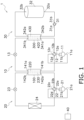
- the refrigerant cycle apparatus 1 is a binary refrigerant cycle apparatus that executes a vapor compression cycle to perform cooling and heating operations of an air-conditioning target space (not shown) such as the interior of a building.
- the refrigerant cycle apparatus 1 heats or cools water, and performs a heating operation and a cooling operation of a target space (not shown) using the water.
- the refrigerant cycle apparatus 1 includes the first heat exchanger 100, a second heat exchanger 300, a first fluid circuit 10, a second fluid circuit 20, a water circuit 30, and a control unit 40.
- a first fluid circulates in the first fluid circuit 10, a second fluid having a lower boiling point than the first fluid circulates in the second fluid circuit 20, and water circulates in the water circuit 30.
- the water circuit 30 is installed indoors
- the second fluid circuit 20 is installed outdoors, although not limited thereto.
- the first fluid circuit 10 may be installed indoors or outdoors, and a part of the first fluid circuit 10 may be installed indoors or outdoors.
- the first heat exchanger 100 causes heat exchange between the first fluid circulating in the first fluid circuit 10 and the second fluid circulating in the second fluid circuit 20.
- the first heat exchanger 100 includes first flow pipes 141a, 141b, second flow pipes 142a, 142b, a first flow path 220, and a second flow path 230.
- the first flow path 220 is a flow path through which the first fluid flows.
- the first flow path 220 is provided between the first flow pipe 1410a and the first flow pipe 141b.
- the second flow path 230 is a flow path through which the second fluid flows.
- the second flow path 230 is formed between the second flow pipe 142a and the second flow pipe 142b.
- the first fluid flowing through the first flow path 220 exchanges heat with the second fluid passing through the second flow path 230.
- a detailed structure of the first heat exchanger 100 will be described later.
- the second heat exchanger 300 causes heat exchange between the first fluid circulating in the first fluid circuit 10 and the water circulating in the water circuit 30.
- the second heat exchanger 300 includes first flow pipes 341a, 341b, second flow pipes 342a, 342b, a first flow path 420, and a second flow path 430.
- the first flow path 420 is a flow path through which the first fluid flows.
- the first flow path 420 is provided between the first flow pipe 341a and the first flow pipe 341b.
- the second flow path 430 is a flow path through which the water flows.
- the second flow path 430 is formed between the second flow pipe 342a and the second flow pipe 342b. The first fluid flowing through the first flow path 420 exchanges heat with the water passing through the second flow path 430.
- the first fluid circuit 10 the first fluid is heated or cooled.
- the first fluid circuit 10 includes a compressor 11, a four-way switching valve 12, an expansion valve 13, the first flow path 220 of the first heat exchanger 100, and the first flow path 420 of the second heat exchanger 300.
- the compressor 11, the four-way switching valve 12, the expansion valve 13, the first flow path 220 of the first heat exchanger 100, and the first flow path 420 of the second heat exchanger 300 are connected by pipes, and the first fluid circulates therein.
- the first fluid is R1234ze.
- the compressor 11 sucks the low-pressure first fluid in the first fluid circuit 10 from a suction portion 11a, compresses it, and discharges the compressed first fluid as the high-pressure first fluid from a discharge portion 11b.
- the four-way switching valve 12 includes a first port 12a, a second port 12b, a third port 12c, and a fourth port 12d.
- the four-way switching valve 12 is switched between a first state and a second state that have different communication states of the first port 12a, the second port 12b, the third port 12c, and the fourth port 12d, on the basis of an instruction from the control unit 40.
- the first state the first port 12a and the second port 12b communicate with each other, and the third port 12c and the fourth port 12d communicate with each other.
- the first port 12a and the fourth port 12d communicate with each other, and the second port 12b and the third port 12c communicate with each other.
- the first port 12a is connected to the discharge portion 11b of the compressor 11.
- the second port 12b is connected to the first flow pipe 341b of the second heat exchanger 300.
- the third port 12c is connected to the suction portion 11a of the compressor 11.
- the fourth port 12d is connected to the first flow pipe 141a of the first heat exchanger 100.
- the expansion valve 13 functions as a decompression apparatus that adjusts a flow rate of the first fluid circulating in the first fluid circuit 10 and reduces the pressure of the first fluid.
- One end of the expansion valve 13 is connected to the first flow pipe 141b of the first heat exchanger 100.
- the other end of the expansion valve 13 is connected to the first flow pipe 341a of the second heat exchanger 300.
- the second fluid circuit 20 includes a compressor 21, a four-way switching valve 22, an expansion valve 23, a heat source heat exchanger 24, and the second flow path 230 of the first heat exchanger 100.
- the compressor 21, the four-way switching valve 22, the expansion valve 23, the heat source heat exchanger 24, and the second flow path 230 of the first heat exchanger 100 are connected by pipes, and the second fluid circulates therein.
- the second fluid is carbon dioxide.
- the compressor 21 sucks the low-pressure second fluid in the second fluid circuit 20 from a suction portion 21a, compresses it, and discharges the compressed second fluid as the high-pressure second fluid from a discharge portion 21b.
- the four-way switching valve 22 includes a first port 22a, a second port 22b, a third port 22c, and a fourth port 22d.
- the four-way switching valve 22 is switched between a first state and a second state that have different communication states of the first port 22a, the second port 22b, the third port 22c, and the fourth port 22d, on the basis of an instruction from the control unit 40.
- the first state the first port 22a and the second port 22b communicate with each other, and the third port 22c and the fourth port 22d communicate with each other.
- the first port 22a and the fourth port 22d communicate with each other, and the second port 22b and the third port 22c communicate with each other.
- the first port 22a is connected to the discharge portion 21b of the compressor 21.
- the second port 22b is connected to the second flow pipe 142b of the first heat exchanger 100.
- the third port 22c is connected to the suction portion 21a of the compressor 21.
- the fourth port 22d is connected to one end of the heat source heat exchanger 24.
- the expansion valve 23 functions as a decompression apparatus that adjusts a flow rate of the second fluid circulating in the second fluid circuit 20 and reduces the pressure of the second fluid.
- One end of the expansion valve 23 is connected to the second flow pipe 142a of the first heat exchanger 100.
- the other end of the expansion valve 23 is connected to the other end of the heat source heat exchanger 24.
- the heat source heat exchanger 24 causes heat exchange between the second fluid circulating in the second fluid circuit 20 and a heat source (for example, outdoor air).
- a heat source for example, outdoor air
- the water having subjected to heat exchange with the first fluid circulates in the water circuit 30.
- the water circuit 30 includes a water circulation pump 31, a water storage tank 32, and the second flow path 430 of the second heat exchanger 300.
- the water circulation pump 31, the water storage tank 32, and the second flow path 430 of the second heat exchanger 300 are connected by pipes, and water circulates therein.
- the water circulation pump 31 circulates water inside the water circuit 30.
- the water circulation pump 31 sucks water inside the water circuit 30 from a suction portion 31a and discharges the water from a discharge portion 31b.
- the suction portion 31a is connected to the second flow pipe 342b of the second heat exchanger 300.
- the water storage tank 32 stores water heated or cooled by the second heat exchanger 300 to heat or cool (in other words, perform heating or cooling) indoor air.
- the water storage tank 32 includes a water intake portion 32a for taking in water circulating in the water circuit 30 and a drain portion 32b for discharging stored water.
- the water intake portion 32a is connected to the discharge portion 31b of the water circulation pump 31.
- the drain portion 32b is connected to the second flow pipe 342b of the second heat exchanger 300.
- the control unit 40 controls the compressors 11, 21, the four-way switching valves 12, 22, the expansion valves 13, 23, and the water circulation pump 31. Although not shown, the control unit 40 is electrically connected to the compressors 11, 21, the four-way switching valves 12, 22, the expansion valves 13, 23, and the water circulation pump 31 so as to enable the transmission and reception of control signals.
- the refrigerant cycle apparatus 1 performs a heating operation and a cooling operation.
- the heating operation is an operation by the refrigerant cycle apparatus 1 to heat water in the water circuit 30.
- the control unit 40 sets the four-way switching valves 12, 22 to the first state, drives the compressors 11, 21 and the water circulation pump 31, and controls the opening degrees of the expansion valves 13, 23.
- the compressor 21 sucks the low-pressure gas-phase second fluid in the second fluid circuit 20 from the suction portion 21a, and discharges it as the high-pressure gas-phase second fluid from the discharge portion 21b.
- the high-pressure gas-phase second fluid passes through the four-way switching valve 22 in the order of the first port 22a and the second port 22b, and reaches the second flow path 230 from the second flow pipe 142a of the first heat exchanger 100.
- the high-pressure gas-phase second fluid In the second flow path 230 of the first heat exchanger 100, the high-pressure gas-phase second fluid is condensed into a high-pressure liquid-phase second fluid. At this time, the second fluid releases heat to the first fluid passing through the first flow path 220.
- the high-pressure liquid-phase second fluid reaches the expansion valve 23.
- the expansion valve 23 set to an appropriate opening degree reduces the pressure of the high-pressure liquid-phase second fluid to form a low-pressure gas-liquid two-phase second fluid.
- the low-pressure gas-liquid two-phase second fluid evaporates in the heat source heat exchanger 24 to become a low-pressure gas-phase second fluid. At this time, the second fluid absorbs heat from the heat source.
- the low-pressure gas-phase second fluid passes through the four-way switching valve 22 in the order of the fourth port 22d and the third port 22c, and then is sucked into the compressor 21 from the suction portion 21a.
- the compressor 11 sucks the low-pressure gas-phase first fluid in the first fluid circuit 10 from the suction portion 11a, and discharges it as the high-pressure gas-phase first fluid from the discharge portion 11b.
- the high-pressure gas-phase first fluid passes through the four-way switching valve 12 in the order of the first port 12a and the second port 12b, and reaches the first flow path 420 from the first flow pipe 341a of the second heat exchanger 300.
- the high-pressure gas-phase first fluid is condensed into a high-pressure liquid-phase first fluid.
- the first fluid releases heat to the water passing through the second flow path 430.
- the high-pressure liquid-phase first fluid reaches the expansion valve 13.
- the expansion valve 13 set to an appropriate opening degree reduces the pressure of the high-pressure liquid-phase first fluid to form a low-pressure gas-liquid two-phase first fluid.
- the low-pressure gas-liquid two-phase first fluid passes through the first flow pipe 141a of the first heat exchanger 100, and then evaporates in the first flow path 220 to become a low-pressure gas-phase first fluid. At this time, the first fluid absorbs heat from the second fluid passing through the second flow path 230.
- the low-pressure gas-phase first fluid passes through the four-way switching valve 12 in the order of the fourth port 12d and the third port 12c, and then is sucked into the compressor 11 from the suction portion 11a.
- the water circulation pump 31 sucks water circulating in the water circuit 30 from the suction portion 31a and discharges it from the discharge portion 31b.
- the discharged water is stored in the water storage tank 32 through the water intake portion 32a.
- the water stored in the water storage tank 32 releases heat to indoor air. In other words, the water stored in the water storage tank 32 heats the indoor air.
- the water stored in the water storage tank 32 passes through the drain portion 32b, and then passes through the second flow pipe 342a of the second heat exchanger 300 to reach the second flow path 430.
- the water having reached the second flow path 430 of the second heat exchanger 300 absorbs heat from the first fluid passing through the first flow path 420.
- the water having absorbed heat is sucked into the water circulation pump 31 from the suction portion 31a.
- the cooling operation is an operation by the refrigerant cycle apparatus 1 to cool water in the water circuit 30.
- the control unit 40 sets the four-way switching valves 12, 22 to the second state, drives the compressors 11, 21 and the water circulation pump 31, and controls the opening degrees of the expansion valves 13, 23.
- the compressor 21 sucks the low-pressure gas-phase second fluid in the second fluid circuit 20 from the suction portion 21a, and discharges it as the high-pressure gas-phase second fluid from the discharge portion 21b.
- the high-pressure gas-phase second fluid passes through the four-way switching valve 22 in the order of the first port 22a and the fourth port 22d, and reaches the heat source heat exchanger 24.
- the heat source heat exchanger 24 the high-pressure gas-phase second fluid is condensed into a high-pressure liquid-phase second fluid. At this time, the second fluid releases heat to the heat source.
- the high-pressure liquid-phase second fluid reaches the expansion valve 23.
- the expansion valve 23 set to an appropriate opening degree reduces the pressure of the high-pressure liquid-phase second fluid to form a low-pressure gas-liquid two-phase second fluid.
- the low-pressure gas-liquid two-phase second fluid passes through the second flow pipe 142b of the first heat exchanger 100, and then evaporates in the second flow path 230 to become a low-pressure gas-phase second fluid. At this time, the second fluid absorbs heat from the first fluid passing through the second flow path 230.
- the low-pressure gas-phase second fluid passes through the four-way switching valve 22 in the order of the second port 22b and the third port 22c, and then is sucked into the compressor 21 from the suction portion 21a.
- the compressor 11 sucks the low-pressure gas-phase first fluid in the first fluid circuit 10 from the suction portion 11a, and discharges it as the high-pressure gas-phase first fluid from the discharge portion 11b.
- the high-pressure gas-phase first fluid passes through the four-way switching valve 12 in the order of the first port 12a and the fourth port 12d, and reaches the first flow path 220 from the first flow pipe 141b of the first heat exchanger 100.
- the high-pressure gas-phase first fluid is condensed into a high-pressure liquid-phase first fluid.
- the first fluid releases heat to the second fluid passing through the second flow path 230.
- the high-pressure liquid-phase first fluid reaches the expansion valve 13.
- the expansion valve 13 set to an appropriate opening degree reduces the pressure of the high-pressure liquid-phase first fluid to form a low-pressure gas-liquid two-phase first fluid.
- the low-pressure gas-liquid two-phase first fluid passes through the first flow pipe 341b of the second heat exchanger 300, and then evaporates in the first flow path 420 to become a low-pressure gas-phase first fluid. At this time, the first fluid absorbs heat from the second fluid passing through the second flow path 430.
- the low-pressure gas-phase first fluid passes through the four-way switching valve 12 in the order of the second port 12b and the third port 12c, and then is sucked into the compressor 11 from the suction portion 11a.
- the water circulation pump 31 sucks water circulating in the water circuit 30 from the suction portion 31a and discharges it from the discharge portion 31b.
- the discharged water is stored in the water storage tank 32 through the water intake portion 32a.
- the water stored in the water storage tank 32 absorbs heat from indoor air. In other words, the water stored in the water storage tank 32 cools the indoor air.
- the water stored in the water storage tank 32 passes through the drain portion 32b, and then passes through the second flow pipe 342a of the second heat exchanger 300 to reach the second flow path 430.
- the water having reached the second flow path 430 of the second heat exchanger 300 releases heat to the first fluid passing through the first flow path 420.
- the water having released heat is sucked into the water circulation pump 31 from the suction portion 31a.
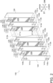
- the first heat exchanger 100 is a plate-shaped heat exchanger including a plurality of first heat transfer plates 110, a plurality of second heat transfer plates 120, a plurality of partition walls 130, a first frame 140, and a second frame 150.
- the first flow path 220 and the second flow path 230 are provided inside the first heat exchanger 100.
- the first heat transfer plate 110, the second heat transfer plate 120, and the partition wall 130 are plate-shaped metal members having the same rectangular outer shape.
- the outer shapes of the first heat transfer plate 110, the second heat transfer plate 120, the partition wall 130, the first frame 140, and the second frame 150 are formed in a band shape elongated in a first direction.
- the plurality of first heat transfer plates 110 and the plurality of second heat transfer plates 120 are alternately laminated with the partition wall 130 interposed therebetween between the first frame 140 and the second frame 150.
- the number of each of the plurality of first heat transfer plates 110 and the plurality of second heat transfer plates 120 is not limited, and is appropriately set in accordance with the required performance.
- the first frame 140, the first heat transfer plate 110, the partition wall 130, the second heat transfer plate 120, and the second frame 150 are integrally joined by, for example, brazing although not limited thereto.
- the first direction may be referred to as a longitudinal direction DL for convenience.
- the width directions of the first heat transfer plate 110, the partition wall 130, and the second heat transfer plate 120 may be referred to as a width direction DW.
- the thickness directions (in other words, the laminating direction) of the first heat transfer plate 110, the partition wall 130, and the second heat transfer plate 120 may be referred to as a thickness direction DT (for all of these, see arrows shown in some of the drawings).
- the upper and lower directions referred to in the following description respectively correspond to "upper” and "lower” shown in some of the drawings.
- the first heat transfer plate 110 forms the first flow path 220 together with the partition wall 130 laminated adjacent thereto.
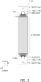
- the first heat transfer plate 110 includes first flow ports 111a, 111b, first through holes 112a, 112b, a first heat transfer region 113, and pluralities of first connection portions 115a, 115b.
- the first flow ports 111a, 111b are holes for introducing or discharging the first fluid into or from the first flow path 220.
- the first flow ports 111a, 111b are formed so as to penetrate the first heat transfer plate 110 along the thickness direction DT.
- the first flow ports 111a, 111b are formed in a circular shape in plan view of the first heat transfer plate 110.
- the first flow ports 111a, 111b are formed at positions spaced from both ends in the longitudinal direction DL of the first heat transfer region 113 by a predetermined distance along the longitudinal direction DL such that the centers of the first flow ports 111a, 111b are located at the center in the width direction DW.
- the first flow port 111a is formed on the upper side than the first heat transfer region 113, and the first flow port 111b is formed on the lower side than the first heat transfer region 113.
- the first through holes 112a, 112b are holes through which the second fluid passes along the thickness direction DT.
- the first through holes 112a, 112b are formed so as to penetrate the first heat transfer plate 110 along the thickness direction DT.
- the first through holes 112a, 112b are formed in a circular shape in plan view of the first heat transfer plate 110.
- the first through holes 112a, 112b are formed at positions spaced from the first flow ports 111a, 111b toward the ends in the longitudinal direction DL of the first heat transfer plate 110 with a predetermined distance along the longitudinal direction DL such that the centers of the first flow through holes 112a, 112b are located at the center in the width direction DW.
- the first through holes 112a, 112b are formed at positions opposite to the first heat transfer region 113 with the first flow ports 111a, 111b interposed therebetween in the longitudinal direction DL.
- the first through hole 112a is formed on the upper side than the first flow port 111a, and the first through hole 112b is formed on the lower side than the first flow port 111b.
- the first heat transfer region 113 is a region in which the first fluid having flowed in from the first flow ports 111a, 111b exchanges heat with the second fluid while passing therethrough.
- the first heat transfer region 113 is a rectangular region having substantially the same width as the first heat transfer plate 110.
- the first heat transfer region 113 is formed from the center of the first heat transfer plate 110 toward both ends in the longitudinal direction DL to the end portions on the first heat transfer region 113 side of the first connection portions 115a, 115b.
- first heat transfer flow paths 114 which are groove-shaped flow paths through which the first fluid having flowed in from the first flow ports 111a, 111b passes, are formed.
- the first heat transfer flow paths 114 are each a groove formed along the longitudinal direction DL.
- the plurality of first heat transfer flow paths 114 are formed at predetermined intervals along the width direction DW of the first heat transfer plate 110.
- the first connection portions 115a are each a groove-shaped flow path having one end connected to the first flow port 111a and the other end connected to an upper end portion of the first heat transfer region 113 in the longitudinal direction DL.
- the first connection portion 115b are each a groove-shaped flow path having one end connected to the first flow port 111b and the other end connected to a lower end portion of the first heat transfer region 113 in the longitudinal direction DL.
- the adjacent first connection portions 115a are separated from each other by a first separation portion 116a.
- the adjacent first connection portions 115b are separated from each other by a first separation portion 116b.
- the first flow path 220 includes the first heat transfer region 113 (first heat transfer flow path 114) and the first connection portions 115a, 115b connected to both ends of the first heat transfer region 113. Therefore, the first heat exchanger 100 includes the same number of first flow paths 220 as the number of the first heat transfer plates 110.
- first connection portions 115a, 115b are formed linearly as shown in Fig. 4 .
- the first connection portions 115a, 115b are formed such that the flow path cross sectional area increases from the first flow ports 111a, 111b toward the first heat transfer region 113.
- 18 first connection portions 115a, 115b are connected to one first flow port 111a, 111b.
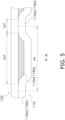
- the first connection portions 115a, 115b may be formed such that, in a cross section orthogonal to the flow direction of the first fluid, the first separation portions 116a, 116b separating the adjacent first connection portions 115a, 115b from each other satisfy the following relation of (Expression 1), preferably of (Expression 2). 0.005 ⁇ La 1 / P 1 ⁇ 0.15 0.005 ⁇ La 1 / P 1 ⁇ 0.05
- La1 is a length along which the first separation portion 116a, 116b is in contact with the partition wall 130.
- P1 is an interval between the adjacent first separation portions 116a, 116b.
- the first heat transfer region 113 (first heat transfer flow path 114) and the first connection portions 115a, 115b are formed on one surface of the first heat transfer plate 110.
- the first flow ports 111a, 111b, the first through holes 112a, 112b, the first heat transfer region 113, and the first connection portions 115a, 115b are formed by, for example, press working although not limited thereto.
- the second heat transfer plate 120 forms the second flow path 230 together with the partition wall 130 laminated adjacent thereto.
- the second heat transfer plate 120 includes second flow ports 121a, 121b, second through holes 122a, 122b, a second heat transfer region 123, pluralities of second connection portions 125a, 125b, and second protrusion portions 127a, 127b.
- the second flow ports 121a, 121b are holes for introducing or discharging the second fluid into or from the second flow path 111.
- the second flow ports 121a, 121b are formed so as to penetrate the second heat transfer plate 120 along the thickness direction DT.
- the second flow ports 121a, 121b are formed in a circular shape in plan view of the second heat transfer plate 120.
- the second flow ports 121a, 121b are formed at positions spaced from the second through holes 122a, 122b toward the ends in the longitudinal direction DL of the second heat transfer plate 120 with a predetermined distance along the longitudinal direction DL such that the centers of the second flow ports 121a, 121b are located at the center in the width direction DW.
- the second flow ports 121a, 121b are formed at positions opposite to the second heat transfer region 123 with the second through holes 122a, 122b interposed therebetween.
- the second flow port 121a is formed on the lower side than the second heat transfer region 123
- the second flow port 121b is formed on the upper side than the second heat transfer region 123.
- the second flow port 121a and the first through hole 112a have the same shape, and are formed at positions overlapping each other in plan view in a state where the first heat transfer plate 110 and the second heat transfer plate 120 are laminated.
- the second flow port 121b and the first through hole 112b have the same shape, and are formed at positions overlapping each other in plan view in a state where the first heat transfer plate 110 and the second heat transfer plate 120 are laminated.
- the second through holes 122a, 122b are holes through which the second fluid passes along the thickness direction.
- the second through holes 122a, 122b are formed so as to penetrate the second heat transfer plate 120 in the thickness direction.
- the second through holes 122a, 122b are formed in a circular shape in plan view of the second heat transfer plate 120.
- the second through holes 122a, 122b are formed at positions spaced with a predetermined distance along the longitudinal direction DL from both ends of the second heat transfer region 123 in the longitudinal direction DL such that the centers of the second through holes 122a, 122b are located at the center in the width direction DW.
- the second through hole 122a is formed on the lower side than the second flow port 121a
- the second through hole 122b is formed on the upper side than the second flow port 121b.
- the second through hole 122a and the first flow port 111a have the same shape, and are formed at positions overlapping each other in plan view in a state where the first heat transfer plate 110 and the second heat transfer plate 120 are laminated.
- the second through hole 122b and the first flow port 111b have the same shape, and are formed at positions overlapping each other in plan view in a state where the first heat transfer plate 110 and the second heat transfer plate 120 are laminated.
- the second heat transfer region 123 is a region in which the second fluid having flowed in from the second flow ports 121a, 121b exchanges heat with the first fluid while passing therethrough.
- the second heat transfer region 123 is a rectangular region having substantially the same width as the second heat transfer plate 120.
- the second heat transfer region 123 is formed from the center of the second heat transfer plate 120 toward both ends in the longitudinal direction DL to the end portions on the second heat transfer region 123 side of the second connection portions 125a, 125b.
- a plurality of second heat transfer flow paths 124 which are groove-shaped flow paths through which the second fluid having flowed in from the second flow ports 121a, 121b passes, are formed.
- the second heat transfer flow paths 124 are each a groove formed along the longitudinal direction DL.
- the plurality of second heat transfer flow paths 124 are formed at predetermined intervals along the width direction DW of the second heat transfer plate 120.
- the second heat transfer region 123 and the first heat transfer region 113 have the same shape, and are formed at positions overlapping each other in plan view in a state where the first heat transfer plate 110 and the second heat transfer plate 120 are laminated.
- the plurality of second heat transfer flow paths 124 and the plurality of first heat transfer flow paths 114 have the same shape, and are formed at positions overlapping each other in plan view in a state where the first heat transfer plate 110 and the second heat transfer plate 120 are laminated.
- the second connection portions 125a are each a groove-shaped flow path having one end connected to the second flow port 121a and the other end connected to a lower end portion of the second heat transfer region 123 in the longitudinal direction DL.
- the second connection portion 125bs are each a groove-shaped flow path having one end connected to the second flow port 121b and the other end connected to an upper end portion of the second heat transfer region 123 in the longitudinal direction DL.
- the second connection portions 125a, 125b are formed so as to go around the outer side of the second through holes 122a, 122b from the second flow ports 121a, 121b toward the second heat transfer region 123.
- the adjacent second connection portions 125a are separated from each other by a second separation portion 126a.
- the adjacent second connection portions 125b are separated from each other by the second separation portion 126b.
- the second flow path 230 includes the second heat transfer region 123 (second heat transfer flow path 124) and the second connection portions 125a, 125b connected to both ends of the second heat transfer region 123. Therefore, the first heat exchanger 100 includes the same number of second flow paths 230 as the number of the second heat transfer plates 120.
- the second connection portions 125a, 125b are formed in a curved shape as shown in Fig. 7 .
- the second connection portions 125a, 125b are formed such that the flow path cross sectional area increases from the second flow ports 121a, 121b toward the second heat transfer region 123.
- 12 second connection portions 125a, 125b are connected to one first flow port 111a, 111b. More specifically, as shown in Fig. 6 and Fig.
- the second connection portions 125a, 125b connected to one first flow port 111a, 111b are divided into two in the width direction DW in a unit of six, and are formed so as to go around the outer side of the second through holes 122a, 122b.
- the second protrusion portions 127a, 127b are provided in the second connection portions 125a, 125b.
- the second protrusion portions 127a, 127b define the second connection portions 125a, 125b, and limit force (pressure) that the partition wall 130 receives from the second fluid.
- the second protrusion portions 127a are each formed in a linear shape projecting with a predetermined length from the second heat transfer region 123 toward the second connection portion 125a in plan view.
- the second protrusion portions 127b are each formed in a linear shape projecting with a predetermined length from the second heat transfer region 123 toward the second connection portion 125b in plan view.
- the second protrusion portions 127a, 127b are formed at four inner connection portions among the second connection portions 125a, 125b divided into two in a unit of six, although not limited thereto.
- the pluralities of second connection portions 125a, 125b may be formed such that, in a cross section orthogonal to the flow direction of the second fluid, the second separation portions 126a, 126b or the second protrusion portions 127a, 127b separating the adjacent second connection portions 125a, 125b from each other satisfy the following relation of (Expression 3), preferably of (Expression 4). 0.005 ⁇ La 2 / P 2 ⁇ 0.15 0.02 ⁇ La 2 / P 2 ⁇ 0.05
- La2 is a length along which the second separation portion 126a, 126b or the second protrusion portion 127a, 127b is jointed to the partition wall 130.
- the P2 is an interval between the adjacent second separation portions 126a, 126b or second protrusion portions 127a, 127b.
- the second heat transfer region 123 (second heat transfer flow path 124) and the second connection portions 125a, 125b are formed on one surface of the second heat transfer plate 120.
- the second flow ports 121a, 121b, the second through holes 122a, 122b, the second heat transfer region 123, the second connection portions 125a, 125b, and the second protrusion portions 127a, 127b are formed by, for example, press working although not limited thereto.
- the partition wall 130 is a flat plate that separates the first heat transfer plate 110 and the second heat transfer plate 120 from each other in the thickness direction DT.
- the partition wall 130 includes two first flow holes 131a, 131b and two second flow holes 132a, 132b.
- the first flow holes 131a, 131b are holes through which the first fluid passes along the thickness direction DT.
- the first flow holes 131a, 131b are formed so as to penetrate the partition wall 130 along the thickness direction DT.
- the first flow holes 131a, 131b are formed in a circular shape in plan view of the partition wall 130.
- the first flow hole 131a, the first flow port 111a, and the second through hole 122b have the same shape, and are formed at positions overlapping each other in plan view in a state where the partition wall 130, the first heat transfer plate 110, and the second heat transfer plate 120 are laminated.
- the first flow hole 131b, the first flow port 111b, and the second through hole 122a have the same shape, and are formed at positions overlapping each other in plan view in a state where the partition wall 130, the first heat transfer plate 110, and the second heat transfer plate 120 are laminated.
- the second flow holes 132a, 132b are holes through which the second fluid passes along the thickness direction.
- the second flow holes 132a, 132b are formed so as to penetrate the partition wall 130 along the thickness direction.
- the second flow holes 132a, 132b are formed in a circular shape in plan view of the partition wall 130.
- the second flow hole 132a, the second flow port 121b, and the first through hole 112a have the same shape, and are formed at positions overlapping each other in plan view in a state where the partition wall 130, the first heat transfer plate 110, and the second heat transfer plate 120 are laminated.
- the second flow hole 132b, the second flow port 121a, and the first through hole 112b have the same shape, and are formed at positions overlapping each other in plan view in a state where the partition wall 130, the first heat transfer plate 110, and the second heat transfer plate 120 are laminated.
- the plurality of first heat transfer plates 110, the plurality of second heat transfer plates 120, and the plurality of partition walls 130 are laminated, whereby the first flow holes 131a, the first flow ports 111a, and the second through holes 122b communicate with each other.
- the first flow holes 131a, the first flow ports 111a, and the second through holes 122b that communicate with each other form a first communication path 211a extending along the thickness direction DT.
- the first communication path 211a communicates with the first flow path 220 through the first flow port 111a.
- the plurality of first heat transfer plates 110, the plurality of second heat transfer plates 120, and the plurality of partition walls 130 are laminated, whereby the first flow holes 131b, the first flow ports 111b, and the second through holes 122a communicate with each other.
- the first communication path 211b communicates with the first flow path 220 through the first flow port 111b.
- the plurality of first heat transfer plates 110, the plurality of second heat transfer plates 120, and the plurality of partition walls 130 are laminated, whereby the second flow holes 132b, the second flow ports 121a, and the first through holes 112b communicate with each other.
- the second communication path 212a communicates with the second flow path 230 through the second flow port 121a.
- the plurality of first heat transfer plates 110, the plurality of second heat transfer plates 120, and the plurality of partition walls 130 are laminated, whereby the second flow holes 132a, the second flow ports 121b, and the first through holes 112a communicate with each other.
- the second communication path 212b communicates with the second flow path 230 through the second flow port 121b.
- the first frame 140 and the second frame 150 are plate-shaped metal members that sandwich, at both ends in the thickness direction DT, the plurality of first heat transfer plates 110 and the plurality of second heat transfer plates 120 alternately laminated with the partition wall 130 interposed therebetween.
- the first frame 140 includes the first flow pipe 141a, the first flow pipe 141b, the second flow pipe 142a, and the second flow pipe 142b.
- the first flow pipe 141a penetrates the first frame 140 and communicates with the first communication path 211a.
- the first flow pipe 141b penetrates the first frame 140 and communicates with the first communication path 211b.
- the second flow pipe 142a penetrates the first frame 140 and communicates with the second communication path 212a.
- the second flow pipe 142b penetrates the first frame 140 and communicates with the second communication path 212b.
- the low-pressure gas-liquid two-phase first fluid introduced from the first flow pipe 141a of the first heat exchanger 100 passes through the first communication path 211a and flows into the first flow path 220 from the first flow port 111a.
- the gas-liquid two-phase first fluid having flowed into the first flow path 220 passes through the first connection portion 115a, the first heat transfer region 113 (first heat transfer flow path 114), and the first connection portion 115b in this order.
- the first fluid flowing through the first heat transfer region 113 exchanges heat with the second fluid in the second flow path 230 adjacent thereto through the partition wall 130, evaporates, and absorbs heat from the second fluid.
- the first heat exchanger 100 functions as an evaporator for the first fluid.
- the evaporated first fluid becomes a low-pressure gas-phase first fluid, passes through the first flow port 111b and the first communication path 211b, and is discharged from the first flow pipe 141b.
- the high-pressure gas-phase second fluid introduced from the second flow pipe 142a of the first heat exchanger 100 passes through the second communication path 212a and flows into the second flow path 230 from the second flow port 121a.
- the high-pressure gas-phase second fluid having flowed into the second flow path 230 passes through the second connection portion 125a, the second heat transfer region 123 (second heat transfer flow path 124), and the second connection portion 125b in this order.
- the second fluid flowing through the second heat transfer region 123 exchanges heat with the first fluid in the first flow path 220 adjacent thereto through the partition wall 130, is condensed, and releases heat.
- the first heat exchanger 100 functions as a condenser for the second fluid.
- the condensed second fluid becomes a high-pressure liquid-phase second fluid, passes through the second flow port 121b and the second communication path 212b, and is discharged from the second flow pipe 142b.
- the high-pressure gas-phase first fluid introduced from the first flow pipe 141b of the first heat exchanger 100 passes through the first communication path 211b and flows into the first flow path 220 from the first flow port 111b.
- the high-pressure gas-phase first fluid having flowed into the first flow path 220 passes through the first connection portion 115b, the first heat transfer region 113 (first heat transfer flow path 114), and the first connection portion 115a in this order.
- the first fluid flowing through the first heat transfer region 113 exchanges heat with the second fluid in the second flow path 230 adjacent thereto through the partition wall 130, is condensed, and releases heat to the second fluid.
- the first heat exchanger 100 functions as a radiator for the first fluid.
- the condensed first fluid becomes a high-pressure liquid-phase first fluid, passes through the first flow port 111a and the first communication path 211a, and is discharged from the first flow pipe 141a.
- the low-pressure gas-liquid two-phase second fluid introduced from the second flow pipe 142b of the first heat exchanger 100 passes through the second communication path 212b, and flows into the second flow path 230 from the second flow port 121b.
- the low-pressure gas-liquid two-phase second fluid having flowed into the second flow path 230 passes through the second connection portion 125b, the second heat transfer region 123 (second heat transfer flow path 124), and the second connection portion 125a in this order.
- the second fluid flowing through the second heat transfer region 123 exchanges heat with the first fluid in the first flow path 220 adjacent thereto through the partition wall 130, evaporates, and absorbs heat from the first fluid.
- the first heat exchanger 100 functions as an evaporator for the second fluid.
- the evaporated second fluid becomes a low-pressure gas-phase second fluid, passes through the second flow port 121a and the second communication path 212a, and is discharged from the second flow pipe 142a.
- the first heat exchanger 100 includes the first heat transfer plate 110 and the second heat transfer plate 120 that are laminated on each other.
- the first heat transfer plate 110 includes the first flow ports 111a, 111b, the first through holes 112a, 112b, the first heat transfer region 113, and the first connection portions 115a, 115b.
- the first flow ports 111a, 111b introduce or discharge the first fluid.
- the second fluid having a lower boiling point than the first fluid passes through the first through holes 112a, 112b in the thickness direction.
- the first heat transfer region 113 is a region in which the first fluid having flowed in from the first flow ports 111a, 111b exchanges heat with the second fluid while passing therethrough.
- One ends of the first connection portions 115a, 115b are connected to the first flow ports 111a, 111b, and the other ends thereof are connected to the first heat transfer region 113.
- the second heat transfer plate 120 includes the second flow ports 121a, 121b, the second through holes 122a, 122b, the second heat transfer region 123, and the second connection portions 125a, 125b.
- the second flow ports 121a, 121b communicate with the first through holes 112a, 112b, and introduce or discharge the second fluid.
- the first fluid passes through the second through holes 122a, 122b in the thickness direction.
- the second heat transfer region 123 is a region in which the second fluid having flowed in from the second flow ports 121a, 121b exchanges heat with the first fluid while passing therethrough.
- One ends of the second connection portions 125a, 125b are connected to the second flow ports 121a, 121b, and the other ends thereof are connected to the second heat transfer region 123.
- the second flow ports 121a, 121b are formed at positions opposite to the second heat transfer region 123 with the second through holes 122a, 122b interposed therebetween.
- the second connection portions 125a, 125b are formed so as to go around the outer side of the second through holes 122a, 122b, and include the second protrusion portions 127a, 127b.
- the heat exchanger including two heat transfer plates, if the length of the flow path through which the first fluid flows is the same as the length of the flow path through which the second fluid flows, the same degree of pressure loss occurs in the two fluids. In comparison of the rates of pressure reduction caused by the pressure loss occurred in this way, the pressure of one of the two fluids that has a lower pressure at the time of inflow is reduced at a larger rate. As a result, there is a problem that the heat exchanger cannot sufficiently exert the heat exchange performance.
- the second connection portions 125a, 125b are formed so as to go around the outer side of the second through holes 122a, 122b.
- the lengths of the flow paths of the first connection portions 115a, 115b through which the first fluid passes are formed to be shorter than the lengths of the flow paths of the second connection portions 125a, 125b through which the second fluid having a lower boiling point than the first fluid passes. Therefore, it is possible to make the pressure loss occurred in the first fluid when passing through the first connection portions 115a, 115b smaller than the pressure loss occurred in the second fluid when passing through the second connection portions 125a, 125b. This suppresses the reduction of the pressure of the first fluid at a large rate. Therefore, in the first heat exchanger 100, it is possible to secure the heat exchange performance even in a case where two fluids have different pressures at the time of inflow.
- the first heat exchanger 100 includes the partition wall 130.
- the partition wall 130 is a plate-shaped member laminated between the first heat transfer plate 110 and the second heat transfer plate 120.
- the length along which the first separation portion 116a, 116b separating the adjacent first connection portions 115a, 115b from each other is in contact with the partition wall 130 is La1 and the interval between the adjacent first separation portions is P1, the first connection portions 115a, 115b are formed so as to satisfy the relation: 0.005 ⁇ La 1 / P 1 ⁇ 0.15
- the force (pressure) that the partition wall 130 receives from the first fluid passing through the first connection portions 115a, 115b is limited, thereby suppressing the excess over the pressure resistance strength.
- connection portions 115a, 115b are formed so as to satisfy the relation: 0.005 ⁇ La 1 / P 1 ⁇ 0.05
- the force (pressure) that the partition wall 130 receives from the first fluid passing through the first connection portions 115a, 115b is limited, thereby suppressing the excess over the pressure resistance strength.
- the force (pressure) that the partition wall 130 receives from the second fluid passing through the second connection portions 125a, 125b is limited, thereby suppressing the excess over the pressure resistance strength.
- connection portions 125a, 125b are formed so as to satisfy the relation: 0.02 ⁇ L 2 / P 2 ⁇ 0.15
- the force (pressure) that the partition wall 130 receives from the second fluid passing through the second connection portions 125a, 125b is limited, thereby suppressing the excess over the pressure resistance strength.
- the second connection portions 125a, 125b are not limited to the above-described aspect as long as they are formed so as to go around the outer side of the second through holes 122a, 122b and are partitioned by the protrusion portions.
- the second connection portion 125b of the first heat exchanger 100 is a planar region (a hatched region in Fig. 9 ) provided on the outer side of the second through hole 122b, and includes a plurality of second protrusion portions 128b formed in a circular shape in plan view.
- the second protrusion portions 128b each have a radius of 1 mm in plan view and a height of 0.5 mm in the thickness direction DT, and are arranged in the longitudinal direction DL and the width direction DW at intervals of 1 mm.
- the second protrusion portions 128b are formed by, for example, press working or etching although not limited thereto.
- the second connection portion 125a provided on the lower side of the second heat transfer plate 120 also has the same shape, and includes a plurality of second protrusion portions 128a.
- the shape of the second protrusion portions 128a, 128b is not limited to a circular shape.
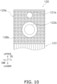
- the shape of the second protrusion portions 128a, 128b may be any one of a triangular shape (see Fig. 10 ), a quadrangular shape (see Fig. 11 ), and a teardrop shape (see Fig. 12 ) in plan view.
- the pluralities of second protrusion portions 128a, 128b of the second connection portion 125b may have mutually different shapes.
- the first connection portions 115a, 115b may be formed in a curved shape.
- the first connection portion 115a of the first heat exchanger 100 according to Modification B is formed in a curved shape, as shown in Fig. 13 .
- the first connection portion 115b provided on the lower side of the first heat transfer plate 110 also has the same shape.
- R1234ze is exemplified as the first fluid
- carbon dioxide is exemplified as the second fluid
- the first fluid there may be used, for example, R32, an HFO-based refrigerant, a mixed refrigerant of R32 and an HFO-based first fluid, carbon dioxide, ammonia, propane, or the like.
- the second fluid only needs to be a fluid having a lower boiling point than the first fluid, and there may be used, for example, R-32, an HFO-based refrigerant, a mixed refrigerant of HFC-32 and an HFO-based refrigerant, a refrigerant of carbon dioxide, ammonia, propane, or the like, water, antifreeze, or the like.
- the first heat exchanger 100 is formed such that the first fluid flowing through the first flow path 220 and the second fluid flowing through the second flow path 230 form counter flows.
- the first heat exchanger 100 may be formed such that the first fluid flowing through the first flow path 220 and the second fluid flowing through the second flow path 230 form parallel flows.
- all of the first flow pipe 141a, the first flow pipe 141b, the second flow pipe 142a, and the second flow pipe 142b are formed in the first frame 140.
- at least a part of the first flow pipe 141a, the first flow pipe 141b, the second flow pipe 142a, and the second flow pipe 142b may be formed in the second frame 150.
- the first connection portion 115a, 115b is not limited to the above-described aspect as long as one end is connected to the first flow port 111a, and the other end is connected to the first heat transfer region 113.
- the first connection portion 115a may further include a first protrusion portion 117a.
- the first connection portion 115b may further include a first protrusion portion 117b.
- the first protrusion portion 117a defines the first connection portion 115a and limits the force (pressure) that the partition wall 130 receives from the first fluid.
- the first protrusion portion 117a is formed in a linear shape projecting with a predetermined length from the first heat transfer region 113 toward the first connection portion 115a in plan view.
- the first connection portion 115b provided on the lower side of the first heat transfer plate 110 also has the same shape, and includes a plurality of first protrusion portions 117b.
- the first connection portion 115a of the first heat exchanger 100 according to Modification G is a planar region provided on the outer side of the first flow port 111a, and includes a plurality of first protrusion portions 117a formed in a circular shape in plan view.
- the first heat transfer plate 110 includes a clearance 119a, which is a band-like region where the first connection portion 115a is not provided over a predetermined width, between the upper end portion and the first connection portion 115a in plan view.
- a clearance 119a With the clearance 119a, it is possible to suppress a case where the length of the flow path of the first connection portion 115a through which the first fluid passes is longer than that of the second connection portion 125a through which the second fluid passes.
- the first protrusion portions 117a each has a radius of 1 mm in plan view and a height of 0.5 mm in the thickness direction DT, and are arranged in the longitudinal direction DL and the width direction DW at intervals of 1 mm.
- the first protrusion portions 117a are formed by, for example, press working or etching although not limited thereto.
- the first connection portion 115b provided on the lower side of the first heat transfer plate 110 also has the same shape, and includes a plurality of first protrusion portions 117b.
- the shape of the first protrusion portions 117a, 117b is not limited to a circular shape.
- the shape of the first protrusion portions 117a, 117b may be any one of a triangular shape, a quadrangular shape, and a teardrop shape, which are shown in Fig. 10 to Fig. 13 as the examples of the second protrusion portions 128b, in plan view.
- the pluralities of first protrusion portions 117a, 117b of the first connection portions 115a, 115b may have mutually different shapes.
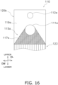
- the shape of the planar first connection portion 115a may be trapezoid with the width expanding from the first flow port 111a toward the first heat transfer region 113, as shown in Fig. 16 .
- the first connection portion 115b provided on the lower side of the first heat transfer plate 110 is formed in the same manner.
- the water heater 2 including the first heat exchanger 100 according to a second embodiment of the present disclosure will be described with reference to Fig. 12 .
- the water heater 2 heats water supplied from the outside. Note that in the following description, the same or corresponding characteristics as those of the first embodiment are denoted by the same reference numerals, and the description thereof will be omitted.
- the water heater 2 includes the first heat exchanger 100, a water circuit 50, a heat source side circuit 60, and a hot water supply tank 70.
- the water circuit 50 is a circuit for circulating water.
- the heat source side circuit 60 is a circuit for circulating carbon dioxide, which is a fluid having a lower boiling point than water. The heat exchange between water and carbon dioxide is performed in the first heat exchanger 100.
- the water circuit 50 is installed indoors, and the heat source side circuit 60 is installed outdoors.
- Water is an example of the first fluid.
- Carbon dioxide is an example of the second fluid.
- the water circuit 50 is an example of the first fluid circuit.
- the heat source side circuit 60 is an example of the second fluid circuit.
- the water circuit 50 includes a water circulation pump 51, a use side heat exchanger 52, and the first flow path 220 of the first heat exchanger 100.
- the water circulation pump 51 circulates water inside the water circuit 50.
- the water circulation pump 51 sucks water inside the water circuit 50 from a suction portion 51a and discharges the water from a discharge portion 51b.
- the suction portion 51a is connected to the first flow pipe 141b of the first heat exchanger 100.
- the use side heat exchanger 52 causes heat exchange between water circulating in the water circuit 50 and water stored in the hot water supply tank 70.
- the use side heat exchanger 52 is disposed inside the hot water supply tank 70 so as to enable the heat exchange between the water passing in the use side heat exchanger 52 and the water stored in the hot water supply tank 70.
- One end of the use side heat exchanger 52 is connected to the discharge portion 51b of the water circulation pump 51.
- the other end of the use side heat exchanger 52 is connected to the first flow pipe 141a of the first heat exchanger 100.
- the heat source side circuit 60 includes a heat source side compressor 61, a heat source side expansion valve 62, a heat source side heat exchanger 63, and the second flow path 230 of the first heat exchanger 100.
- the heat source side compressor 61 sucks the low-pressure gas-phase carbon dioxide in the heat source side circuit 60 from a suction portion 61a, compresses it, and discharges it as the high-pressure gas-phase carbon dioxide from a discharge portion 61b.
- the discharge portion 61b is connected to the second flow pipe 142a of the first heat exchanger 100.
- the heat source side expansion valve 62 functions as a decompression apparatus that adjusts a flow rate of the carbon dioxide circulating through the heat source side circuit 60 and reduces the pressure of the carbon dioxide.
- One end of the heat source side expansion valve 62 is connected to the second flow pipe 142b of the first heat exchanger 100.
- the other end of the heat source side expansion valve 62 is connected to one end of the heat source side heat exchanger 63.
- the heat source side heat exchanger 63 functions as an evaporator, and causes heat exchange between carbon dioxide and a heat source (for example, outside air).
- the other end of the heat source side heat exchanger 63 is connected to the suction portion 61a of the heat source side compressor 61.
- the hot water supply tank 70 stores water supplied from the outside.
- the stored water exchanges heat with the water passing through the use side heat exchanger 42.
- the hot water supply tank 70 takes in water supplied from the outside from a water inlet part 70b and stores it.
- the stored water is discharged from a water outlet part 70a.
- a control unit (not shown) drives the water circulation pump 51 and the heat source side compressor 61, and sets the opening degree of the heat source side expansion valve 62 to an appropriate opening degree corresponding to a target temperature of the water discharged from the hot water supply tank 70.
- the water circulation pump 51 When the water circulation pump 51 is driven, the water sucked from the suction portion 51a is discharged from the discharge portion 51b.
- the discharged water exchanges heat with the water stored in the hot water supply tank 70 in the use side heat exchanger 52.
- the water subjected to heat exchange and circulating in the water circuit 30 passes through the first flow pipe 141a of the first heat exchanger 100 and flows into the first flow path 220.
- the water passing through the first flow path 220 absorbs heat from the carbon dioxide passing through the second flow path 230 (in other words, is heated by the carbon dioxide).
- the water having absorbed heat and circulating in the liquid water circuit 30 passes through the first flow pipe 141b and flows out of the first flow path 220.
- the water circulation pump 51 sucks the water having flowed out of the first flow path 220 from the suction portion 51a and discharges it from the discharge portion 51b.
- the heat source side compressor 61 sucks the low-pressure gas-phase carbon dioxide in the heat source side circuit 60 from the suction portion 61a, and discharges it as the high-pressure gas-phase carbon dioxide from the discharge portion 61b.
- the high-pressure gas-phase carbon dioxide passes through the second flow pipe 142a of the first heat exchanger 100 and flows into the second flow path 230.
- the first heat exchanger 100 condenses the high-pressure gas-phase carbon dioxide into high-pressure liquid-phase carbon dioxide by releasing heat. At this time, the carbon dioxide releases heat to the water passing through the first flow path 220 of the first heat exchanger 100 (in other words, heats the water).
- the high-pressure liquid-phase carbon dioxide passes through the second flow pipe 142b, flows out of the second flow path 230, and reaches the heat source side expansion valve 62.
- the heat source side expansion valve 62 with an appropriate opening degree set decompresses the high-pressure liquid-phase carbon dioxide into low-pressure gas-liquid two-phase carbon dioxide.
- the low-pressure gas-liquid two-phase carbon dioxide reaches the heat source side heat exchanger 63.
- the heat source side heat exchanger 63 evaporates low-pressure gas-liquid two-phase carbon dioxide into low-pressure gas-phase carbon dioxide. At this time, the carbon dioxide absorbs heat from the heat source (outside air).
- the low-pressure gas-phase carbon dioxide flows out of the heat source side heat exchanger 63 and is sucked into the heat source side compressor 61 from the suction portion 61a.
- the first heat exchanger 100 exerts the same effect as in the case where it is used in the refrigerant cycle apparatus 1. Specifically, it is possible to make the pressure loss occurred in water when passing through the first connection portions 115a, 115b smaller than the pressure loss occurred in carbon dioxide when passing through the second connection portions 125a, 125b. This suppresses the reduction of the pressure of water at a large rate. Therefore, in the first heat exchanger 100, it is possible to secure the heat exchange performance even in a case where two fluids have different pressures at the time of inflow.
Landscapes
- Engineering & Computer Science (AREA)
- Physics & Mathematics (AREA)
- Thermal Sciences (AREA)
- Mechanical Engineering (AREA)
- General Engineering & Computer Science (AREA)
- Chemical & Material Sciences (AREA)
- Combustion & Propulsion (AREA)
- Heat-Exchange Devices With Radiators And Conduit Assemblies (AREA)
- Details Of Fluid Heaters (AREA)
Abstract
Description
- The present disclosure relates to a heat exchanger, a refrigerant cycle apparatus, and a water heater.
- There is known a plate-shaped heat exchanger in which a plurality of heat transfer plates are laminated at predetermined intervals in a laminating direction to alternately form a flow path through which a first fluid flows and a flow path through which a second fluid flows and which causes heat exchange between the two fluids.
- PTL 1 (
Japanese Unexamined Patent Application Publication (Translation of PCT Application) No. 2012-512382 - In the heat exchanger of
PTL 1, the length of the flow path through which the first fluid flows is the same as the length of the flow path through which the second fluid flows. Therefore, the same degree of pressure loss occurs in the two fluids inside the heat exchanger. In comparison of the rates of pressure reduction due to the pressure loss occurred in this way, the pressure of one of the two fluids that has a lower pressure at the time of inflow is reduced at a relatively larger rate. As a result, there is a problem that the heat exchanger cannot sufficiently exert the heat exchange performance. - The present disclosure provides a heat exchanger capable of securing the heat exchange performance even in a case where two fluids have different pressures at the time of inflow, and a refrigerant cycle apparatus and a water heater using the same.
- A first heat exchanger of a first aspect includes a first heat transfer plate and a second heat transfer plate that are laminated on each other.
- The first heat transfer plate includes a first flow port, a first through hole, a first heat transfer region, and a first connection portion.
- The first flow port introduces or discharges a first fluid. A second fluid having a lower boiling point than the first fluid passes through the first through hole in a thickness direction. The first heat transfer region is a region in which the first fluid having flowed in from the first flow port exchanges heat with the second fluid while passing therethrough. One end of the first connection portion is connected to the first flow port, and the other end thereof is connected to the first heat transfer region.
- The second heat transfer plate includes a second flow port, a second through hole, a second heat transfer region, and a second connection portion.
- The second flow port communicates with the first through hole and introduces or discharges the second fluid. The first fluid passes through the second through hole in the thickness direction. The second heat transfer region is a region in which the second fluid having flowed in from the second flow port exchanges heat with the first fluid while passing therethrough. The second connection portion has one end connected to the second flow port and the other end connected to the second heat transfer region.
- The second flow port is formed at a position opposite to the second heat transfer region with the second through hole interposed therebetween. The second connection portion is formed so as to go around an outer side of the second through hole, and includes a second protrusion portion.
- In the present heat exchanger, the second connection portion is formed so as to go around the outer side of the second through hole. In other words, the length of the flow path of the first connection portion through which the first fluid passes is formed to be shorter than the length of the flow path of the second connection portion through which the second fluid having a lower boiling point than the first fluid passes. Therefore, it is possible to make the pressure loss occurred in the first fluid when passing through the first connection portion smaller than the pressure loss occurred in the second fluid when passing through the second connection portion. This suppresses the reduction of the pressure of the first fluid at a large rate. Therefore, in the present heat exchanger, it is possible to secure the heat exchange performance even in a case where two fluids have different pressures at the time of inflow.
- A heat exchanger of a second aspect is the heat exchanger of the first aspect, in which the second protrusion portion has a linear shape in plan view.
- A heat exchanger of a third aspect is the heat exchanger of the first aspect or the second aspect, in which the second connection portion has a linear shape in plan view.
- A heat exchanger of a fourth aspect is the heat exchanger of the first aspect, in which the second protrusion portion has a circular shape in plan view.
- A heat exchanger of a fifth aspect is the heat exchanger of the first aspect, in which the second protrusion portion has a triangular shape in plan view.
- A heat exchanger of a sixth aspect is the heat exchanger of the first aspect, in which the second protrusion portion has a quadrangular shape in plan view.
- A heat exchanger of a seventh aspect is the heat exchanger of the first aspect, in which the second protrusion portion has a teardrop shape in plan view.
- A heat exchanger of an eighth aspect is the heat exchanger of the first aspect, in which the first connection portion is formed such that a flow path cross sectional area increases from the first flow port toward the first heat transfer region.
- The present heat exchanger further reduces a pressure loss occurred in the first fluid passing through the first connection portion, and thus further suppresses the reduction of the pressure of the first fluid at a large rate and secures the heat exchange performance more effectively.
- A heat exchanger of a ninth aspect is the heat exchanger of the eighth aspect, in which the first connection portion includes a first protrusion portion, and the first protrusion portion has a linear shape in plan view.
- A heat exchanger of a tenth aspect is the heat exchanger of the eighth aspect, in which the first connection portion includes a first protrusion portion, and the first protrusion portion has a circular shape in plan view.
- A heat exchanger of an eleventh aspect is the heat exchanger of the eighth aspect, in which the first connection portion includes a first protrusion portion, and the first protrusion portion has a triangular shape in plan view.
- A heat exchanger of a twelfth aspect is the heat exchanger of the eighth aspect, in which the first connection portion includes a first protrusion portion, and the first protrusion portion has a quadrangular shape in plan view.
- A heat exchanger of a thirteenth aspect is the heat exchanger of the eighth aspect, in which the first connection portion includes a first protrusion portion, and the first protrusion portion has a teardrop shape in plan view.
- A heat exchanger of a fourteenth aspect is the heat exchanger of any one of the first aspect to the thirteenth aspect, including a partition wall. The partition wall is a plate-shaped member laminated between the first heat transfer plate and the second heat transfer plate. When in a cross section orthogonal to a flow direction of the first fluid, a length along which a first separation portion separating adjacent first connection portions from each other is in contact with the partition wall is La1, and an interval between adjacent first separation portions is P1, the first connection portion is formed so as to satisfy a relation:

- With the first connection portion formed so as to satisfy the above-described relation, the force that the partition wall receives from the first fluid passing through the first connection portion is suppressed from exceeding the pressure resistance strength.
- A heat exchanger of a fifteenth aspect is the heat exchanger of the fourteenth aspect in which the first connection portion is formed so as to satisfy a relation:

- In the present heat exchanger, with the first connection portion formed so as to satisfy the above-described relation, the force that the partition wall receives from the first fluid passing through the first connection portion is more effectively suppressed from exceeding the pressure resistance strength.
- A heat exchanger of a sixteenth aspect is the heat exchanger of any one of the first aspect to the fifteenth aspect, including a partition wall. When in a cross section orthogonal to a flow direction of the second fluid, a length along which a second separation portion or the protrusion portion separating adjacent second connection portions from each other is in contact with the partition wall is La2, and an interval between adjacent second separation portions or second protrusion portions is P2, the second connection portion is formed so as to satisfy a relation:

- In the present heat exchanger, with the second connection portion formed so as to satisfy the above-described relation, the force that the partition wall receives from the second fluid passing through the second connection portion is suppressed from exceeding the pressure resistance strength.
- A heat exchanger according to a seventeenth aspect is the heat exchanger according to the sixteenth aspect in which the second connection portion is formed so as to satisfy a relation:

- In the present heat exchanger, with the second connection portion formed so as to satisfy the above-described relation, the force that the partition wall receives from the second fluid passing through the second connection portion is more effectively suppressed from exceeding the pressure resistance strength.
- A refrigerant cycle apparatus of an eighteenth aspect includes the heat exchanger of any one of the first aspect to the seventeenth aspects, a first fluid circuit in which the first fluid circulates, and a second fluid circuit in which the second fluid circulates.
- A water heater of a nineteenth aspect includes the heat exchanger of any one of the first aspect to the seventeenth aspects, a first fluid circuit in which the first fluid circulates, and a second fluid circuit in which the second fluid circulates.
-
-
Fig. 1 is a schematic configuration diagram showing arefrigerant cycle apparatus 1 including afirst heat exchanger 100. -
Fig. 2 is an exploded perspective view of thefirst heat exchanger 100. -
Fig. 3 is a plan view of a firstheat transfer plate 110. -
Fig. 4 is an enlarged view of the vicinity of the upper end portion of the firstheat transfer plate 110. -
Fig. 5 is a sectional view of a part taken along line A-A' ofFig. 4 . -
Fig. 6 is a plan view of a secondheat transfer plate 120. -
Fig. 7 is an enlarged view of the vicinity of the upper end portion of the secondheat transfer plate 120. -
Fig. 8 is a sectional view of a part taken along line B-B' ofFig. 7 . -
Fig. 9 is an enlarged view of the vicinity of the upper end portion of the secondheat transfer plate 120 of thefirst heat exchanger 100 according to a modification A. -
Fig. 10 is an enlarged view of the vicinity of the upper end portion of the secondheat transfer plate 120 of thefirst heat exchanger 100 according to another example of the modification A. -
Fig. 11 is an enlarged view of the vicinity of the upper end portion of the secondheat transfer plate 120 of thefirst heat exchanger 100 according to another example of the modification A. -
Fig. 12 is an enlarged view of the vicinity of the upper end portion of the secondheat transfer plate 120 of thefirst heat exchanger 100 according to another example of the modification A. -
Fig. 13 is an enlarged view of the vicinity of the upper end portion of the firstheat transfer plate 110 of thefirst heat exchanger 100 according to a modification B. -
Fig. 14 is an enlarged view of the vicinity of the upper end portion of the firstheat transfer plate 110 of thefirst heat exchanger 100 according to a modification F. -
Fig. 15 is an enlarged view of the vicinity of the upper end portion of the firstheat transfer plate 110 of thefirst heat exchanger 100 according to a modification G. -
Fig. 16 is an enlarged view of the vicinity of the upper end portion of the firstheat transfer plate 110 of thefirst heat exchanger 100 according to another example of the modification G. -
Fig. 17 is a schematic configuration diagram showing awater heater 2 including thefirst heat exchanger 100. - First, the
refrigerant cycle apparatus 1 including thefirst heat exchanger 100 according to the first embodiment of the present disclosure will be described. Therefrigerant cycle apparatus 1 is a binary refrigerant cycle apparatus that executes a vapor compression cycle to perform cooling and heating operations of an air-conditioning target space (not shown) such as the interior of a building. - The
refrigerant cycle apparatus 1 heats or cools water, and performs a heating operation and a cooling operation of a target space (not shown) using the water. Therefrigerant cycle apparatus 1 includes thefirst heat exchanger 100, asecond heat exchanger 300, afirst fluid circuit 10, asecond fluid circuit 20, awater circuit 30, and acontrol unit 40. As will be described in detail later, a first fluid circulates in thefirst fluid circuit 10, a second fluid having a lower boiling point than the first fluid circulates in thesecond fluid circuit 20, and water circulates in thewater circuit 30. In the present embodiment, thewater circuit 30 is installed indoors, and thesecond fluid circuit 20 is installed outdoors, although not limited thereto. Thefirst fluid circuit 10 may be installed indoors or outdoors, and a part of thefirst fluid circuit 10 may be installed indoors or outdoors. - The
first heat exchanger 100 causes heat exchange between the first fluid circulating in thefirst fluid circuit 10 and the second fluid circulating in thesecond fluid circuit 20. Thefirst heat exchanger 100 includesfirst flow pipes second flow pipes first flow path 220, and asecond flow path 230. - The
first flow path 220 is a flow path through which the first fluid flows. Thefirst flow path 220 is provided between the first flow pipe 1410a and thefirst flow pipe 141b. Thesecond flow path 230 is a flow path through which the second fluid flows. Thesecond flow path 230 is formed between thesecond flow pipe 142a and thesecond flow pipe 142b. The first fluid flowing through thefirst flow path 220 exchanges heat with the second fluid passing through thesecond flow path 230. A detailed structure of thefirst heat exchanger 100 will be described later. - The
second heat exchanger 300 causes heat exchange between the first fluid circulating in thefirst fluid circuit 10 and the water circulating in thewater circuit 30. Thesecond heat exchanger 300 includesfirst flow pipes second flow pipes first flow path 420, and asecond flow path 430. - The
first flow path 420 is a flow path through which the first fluid flows. Thefirst flow path 420 is provided between thefirst flow pipe 341a and thefirst flow pipe 341b. Thesecond flow path 430 is a flow path through which the water flows. Thesecond flow path 430 is formed between thesecond flow pipe 342a and thesecond flow pipe 342b. The first fluid flowing through thefirst flow path 420 exchanges heat with the water passing through thesecond flow path 430. - In the
first fluid circuit 10, the first fluid is heated or cooled. Thefirst fluid circuit 10 includes acompressor 11, a four-way switching valve 12, anexpansion valve 13, thefirst flow path 220 of thefirst heat exchanger 100, and thefirst flow path 420 of thesecond heat exchanger 300. Thecompressor 11, the four-way switching valve 12, theexpansion valve 13, thefirst flow path 220 of thefirst heat exchanger 100, and thefirst flow path 420 of thesecond heat exchanger 300 are connected by pipes, and the first fluid circulates therein. In the present embodiment, the first fluid is R1234ze. - The
compressor 11 sucks the low-pressure first fluid in thefirst fluid circuit 10 from asuction portion 11a, compresses it, and discharges the compressed first fluid as the high-pressure first fluid from adischarge portion 11b. - The four-
way switching valve 12 includes afirst port 12a, asecond port 12b, a third port 12c, and afourth port 12d. The four-way switching valve 12 is switched between a first state and a second state that have different communication states of thefirst port 12a, thesecond port 12b, the third port 12c, and thefourth port 12d, on the basis of an instruction from thecontrol unit 40. In the first state, thefirst port 12a and thesecond port 12b communicate with each other, and the third port 12c and thefourth port 12d communicate with each other. In the second state, thefirst port 12a and thefourth port 12d communicate with each other, and thesecond port 12b and the third port 12c communicate with each other. - The
first port 12a is connected to thedischarge portion 11b of thecompressor 11. Thesecond port 12b is connected to thefirst flow pipe 341b of thesecond heat exchanger 300. The third port 12c is connected to thesuction portion 11a of thecompressor 11. Thefourth port 12d is connected to thefirst flow pipe 141a of thefirst heat exchanger 100. - The
expansion valve 13 functions as a decompression apparatus that adjusts a flow rate of the first fluid circulating in thefirst fluid circuit 10 and reduces the pressure of the first fluid. - One end of the
expansion valve 13 is connected to thefirst flow pipe 141b of thefirst heat exchanger 100. The other end of theexpansion valve 13 is connected to thefirst flow pipe 341a of thesecond heat exchanger 300. - In the
second fluid circuit 20, the second fluid is heated or cooled. Thesecond fluid circuit 20 includes acompressor 21, a four-way switching valve 22, anexpansion valve 23, a heatsource heat exchanger 24, and thesecond flow path 230 of thefirst heat exchanger 100. Thecompressor 21, the four-way switching valve 22, theexpansion valve 23, the heatsource heat exchanger 24, and thesecond flow path 230 of thefirst heat exchanger 100 are connected by pipes, and the second fluid circulates therein. In the present embodiment, the second fluid is carbon dioxide. - The
compressor 21 sucks the low-pressure second fluid in thesecond fluid circuit 20 from asuction portion 21a, compresses it, and discharges the compressed second fluid as the high-pressure second fluid from adischarge portion 21b. - The four-
way switching valve 22 includes afirst port 22a, asecond port 22b, athird port 22c, and afourth port 22d. The four-way switching valve 22 is switched between a first state and a second state that have different communication states of thefirst port 22a, thesecond port 22b, thethird port 22c, and thefourth port 22d, on the basis of an instruction from thecontrol unit 40. In the first state, thefirst port 22a and thesecond port 22b communicate with each other, and thethird port 22c and thefourth port 22d communicate with each other. In the second state, thefirst port 22a and thefourth port 22d communicate with each other, and thesecond port 22b and thethird port 22c communicate with each other. - The
first port 22a is connected to thedischarge portion 21b of thecompressor 21. Thesecond port 22b is connected to thesecond flow pipe 142b of thefirst heat exchanger 100. Thethird port 22c is connected to thesuction portion 21a of thecompressor 21. Thefourth port 22d is connected to one end of the heatsource heat exchanger 24. - The
expansion valve 23 functions as a decompression apparatus that adjusts a flow rate of the second fluid circulating in thesecond fluid circuit 20 and reduces the pressure of the second fluid. - One end of the
expansion valve 23 is connected to thesecond flow pipe 142a of thefirst heat exchanger 100. The other end of theexpansion valve 23 is connected to the other end of the heatsource heat exchanger 24. - The heat
source heat exchanger 24 causes heat exchange between the second fluid circulating in thesecond fluid circuit 20 and a heat source (for example, outdoor air). - The water having subjected to heat exchange with the first fluid circulates in the
water circuit 30. Thewater circuit 30 includes awater circulation pump 31, awater storage tank 32, and thesecond flow path 430 of thesecond heat exchanger 300. Thewater circulation pump 31, thewater storage tank 32, and thesecond flow path 430 of thesecond heat exchanger 300 are connected by pipes, and water circulates therein. - The
water circulation pump 31 circulates water inside thewater circuit 30. Thewater circulation pump 31 sucks water inside thewater circuit 30 from asuction portion 31a and discharges the water from adischarge portion 31b. - The
suction portion 31a is connected to thesecond flow pipe 342b of thesecond heat exchanger 300. - The
water storage tank 32 stores water heated or cooled by thesecond heat exchanger 300 to heat or cool (in other words, perform heating or cooling) indoor air. Thewater storage tank 32 includes awater intake portion 32a for taking in water circulating in thewater circuit 30 and adrain portion 32b for discharging stored water. - The
water intake portion 32a is connected to thedischarge portion 31b of thewater circulation pump 31. Thedrain portion 32b is connected to thesecond flow pipe 342b of thesecond heat exchanger 300. - The
control unit 40 controls thecompressors way switching valves expansion valves water circulation pump 31. Although not shown, thecontrol unit 40 is electrically connected to thecompressors way switching valves expansion valves water circulation pump 31 so as to enable the transmission and reception of control signals. - The
refrigerant cycle apparatus 1 performs a heating operation and a cooling operation. - The heating operation is an operation by the
refrigerant cycle apparatus 1 to heat water in thewater circuit 30. In the heating operation, thecontrol unit 40 sets the four-way switching valves compressors water circulation pump 31, and controls the opening degrees of theexpansion valves - The
compressor 21 sucks the low-pressure gas-phase second fluid in thesecond fluid circuit 20 from thesuction portion 21a, and discharges it as the high-pressure gas-phase second fluid from thedischarge portion 21b. The high-pressure gas-phase second fluid passes through the four-way switching valve 22 in the order of thefirst port 22a and thesecond port 22b, and reaches thesecond flow path 230 from thesecond flow pipe 142a of thefirst heat exchanger 100. In thesecond flow path 230 of thefirst heat exchanger 100, the high-pressure gas-phase second fluid is condensed into a high-pressure liquid-phase second fluid. At this time, the second fluid releases heat to the first fluid passing through thefirst flow path 220. The high-pressure liquid-phase second fluid reaches theexpansion valve 23. Theexpansion valve 23 set to an appropriate opening degree reduces the pressure of the high-pressure liquid-phase second fluid to form a low-pressure gas-liquid two-phase second fluid. The low-pressure gas-liquid two-phase second fluid evaporates in the heatsource heat exchanger 24 to become a low-pressure gas-phase second fluid. At this time, the second fluid absorbs heat from the heat source. The low-pressure gas-phase second fluid passes through the four-way switching valve 22 in the order of thefourth port 22d and thethird port 22c, and then is sucked into thecompressor 21 from thesuction portion 21a. - The
compressor 11 sucks the low-pressure gas-phase first fluid in thefirst fluid circuit 10 from thesuction portion 11a, and discharges it as the high-pressure gas-phase first fluid from thedischarge portion 11b. The high-pressure gas-phase first fluid passes through the four-way switching valve 12 in the order of thefirst port 12a and thesecond port 12b, and reaches thefirst flow path 420 from thefirst flow pipe 341a of thesecond heat exchanger 300. In thefirst flow path 420 of thesecond heat exchanger 300, the high-pressure gas-phase first fluid is condensed into a high-pressure liquid-phase first fluid. At this time, the first fluid releases heat to the water passing through thesecond flow path 430. The high-pressure liquid-phase first fluid reaches theexpansion valve 13. Theexpansion valve 13 set to an appropriate opening degree reduces the pressure of the high-pressure liquid-phase first fluid to form a low-pressure gas-liquid two-phase first fluid. The low-pressure gas-liquid two-phase first fluid passes through thefirst flow pipe 141a of thefirst heat exchanger 100, and then evaporates in thefirst flow path 220 to become a low-pressure gas-phase first fluid. At this time, the first fluid absorbs heat from the second fluid passing through thesecond flow path 230. The low-pressure gas-phase first fluid passes through the four-way switching valve 12 in the order of thefourth port 12d and the third port 12c, and then is sucked into thecompressor 11 from thesuction portion 11a. - The
water circulation pump 31 sucks water circulating in thewater circuit 30 from thesuction portion 31a and discharges it from thedischarge portion 31b. The discharged water is stored in thewater storage tank 32 through thewater intake portion 32a. The water stored in thewater storage tank 32 releases heat to indoor air. In other words, the water stored in thewater storage tank 32 heats the indoor air. The water stored in thewater storage tank 32 passes through thedrain portion 32b, and then passes through thesecond flow pipe 342a of thesecond heat exchanger 300 to reach thesecond flow path 430. The water having reached thesecond flow path 430 of thesecond heat exchanger 300 absorbs heat from the first fluid passing through thefirst flow path 420. The water having absorbed heat is sucked into thewater circulation pump 31 from thesuction portion 31a. - The cooling operation is an operation by the
refrigerant cycle apparatus 1 to cool water in thewater circuit 30. In the cooling operation, thecontrol unit 40 sets the four-way switching valves compressors water circulation pump 31, and controls the opening degrees of theexpansion valves - The
compressor 21 sucks the low-pressure gas-phase second fluid in thesecond fluid circuit 20 from thesuction portion 21a, and discharges it as the high-pressure gas-phase second fluid from thedischarge portion 21b. The high-pressure gas-phase second fluid passes through the four-way switching valve 22 in the order of thefirst port 22a and thefourth port 22d, and reaches the heatsource heat exchanger 24. In the heatsource heat exchanger 24, the high-pressure gas-phase second fluid is condensed into a high-pressure liquid-phase second fluid. At this time, the second fluid releases heat to the heat source. The high-pressure liquid-phase second fluid reaches theexpansion valve 23. Theexpansion valve 23 set to an appropriate opening degree reduces the pressure of the high-pressure liquid-phase second fluid to form a low-pressure gas-liquid two-phase second fluid. The low-pressure gas-liquid two-phase second fluid passes through thesecond flow pipe 142b of thefirst heat exchanger 100, and then evaporates in thesecond flow path 230 to become a low-pressure gas-phase second fluid. At this time, the second fluid absorbs heat from the first fluid passing through thesecond flow path 230. The low-pressure gas-phase second fluid passes through the four-way switching valve 22 in the order of thesecond port 22b and thethird port 22c, and then is sucked into thecompressor 21 from thesuction portion 21a. - The
compressor 11 sucks the low-pressure gas-phase first fluid in thefirst fluid circuit 10 from thesuction portion 11a, and discharges it as the high-pressure gas-phase first fluid from thedischarge portion 11b. The high-pressure gas-phase first fluid passes through the four-way switching valve 12 in the order of thefirst port 12a and thefourth port 12d, and reaches thefirst flow path 220 from thefirst flow pipe 141b of thefirst heat exchanger 100. In thefirst flow path 220 of thefirst heat exchanger 100, the high-pressure gas-phase first fluid is condensed into a high-pressure liquid-phase first fluid. At this time, the first fluid releases heat to the second fluid passing through thesecond flow path 230. The high-pressure liquid-phase first fluid reaches theexpansion valve 13. Theexpansion valve 13 set to an appropriate opening degree reduces the pressure of the high-pressure liquid-phase first fluid to form a low-pressure gas-liquid two-phase first fluid. The low-pressure gas-liquid two-phase first fluid passes through thefirst flow pipe 341b of thesecond heat exchanger 300, and then evaporates in thefirst flow path 420 to become a low-pressure gas-phase first fluid. At this time, the first fluid absorbs heat from the second fluid passing through thesecond flow path 430. The low-pressure gas-phase first fluid passes through the four-way switching valve 12 in the order of thesecond port 12b and the third port 12c, and then is sucked into thecompressor 11 from thesuction portion 11a. - The
water circulation pump 31 sucks water circulating in thewater circuit 30 from thesuction portion 31a and discharges it from thedischarge portion 31b. The discharged water is stored in thewater storage tank 32 through thewater intake portion 32a. The water stored in thewater storage tank 32 absorbs heat from indoor air. In other words, the water stored in thewater storage tank 32 cools the indoor air. The water stored in thewater storage tank 32 passes through thedrain portion 32b, and then passes through thesecond flow pipe 342a of thesecond heat exchanger 300 to reach thesecond flow path 430. The water having reached thesecond flow path 430 of thesecond heat exchanger 300 releases heat to the first fluid passing through thefirst flow path 420. The water having released heat is sucked into thewater circulation pump 31 from thesuction portion 31a. - The
first heat exchanger 100 is a plate-shaped heat exchanger including a plurality of firstheat transfer plates 110, a plurality of secondheat transfer plates 120, a plurality ofpartition walls 130, afirst frame 140, and asecond frame 150. Thefirst flow path 220 and thesecond flow path 230 are provided inside thefirst heat exchanger 100. - The first
heat transfer plate 110, the secondheat transfer plate 120, and thepartition wall 130 are plate-shaped metal members having the same rectangular outer shape. In the present embodiment, as shown inFig. 2 , the outer shapes of the firstheat transfer plate 110, the secondheat transfer plate 120, thepartition wall 130, thefirst frame 140, and thesecond frame 150 are formed in a band shape elongated in a first direction. - The plurality of first
heat transfer plates 110 and the plurality of secondheat transfer plates 120 are alternately laminated with thepartition wall 130 interposed therebetween between thefirst frame 140 and thesecond frame 150. The number of each of the plurality of firstheat transfer plates 110 and the plurality of secondheat transfer plates 120 is not limited, and is appropriately set in accordance with the required performance. Thefirst frame 140, the firstheat transfer plate 110, thepartition wall 130, the secondheat transfer plate 120, and thesecond frame 150 are integrally joined by, for example, brazing although not limited thereto. - In the following description, the first direction may be referred to as a longitudinal direction DL for convenience. Moreover, the width directions of the first
heat transfer plate 110, thepartition wall 130, and the secondheat transfer plate 120 may be referred to as a width direction DW. Further, the thickness directions (in other words, the laminating direction) of the firstheat transfer plate 110, thepartition wall 130, and the secondheat transfer plate 120 may be referred to as a thickness direction DT (for all of these, see arrows shown in some of the drawings). Moreover, the upper and lower directions referred to in the following description respectively correspond to "upper" and "lower" shown in some of the drawings. - The first
heat transfer plate 110 forms thefirst flow path 220 together with thepartition wall 130 laminated adjacent thereto. The firstheat transfer plate 110 includesfirst flow ports holes heat transfer region 113, and pluralities offirst connection portions - The
first flow ports first flow path 220. Thefirst flow ports heat transfer plate 110 along the thickness direction DT. In the present embodiment, thefirst flow ports heat transfer plate 110. Thefirst flow ports heat transfer region 113 by a predetermined distance along the longitudinal direction DL such that the centers of thefirst flow ports first flow port 111a is formed on the upper side than the firstheat transfer region 113, and thefirst flow port 111b is formed on the lower side than the firstheat transfer region 113. - The first through
holes holes heat transfer plate 110 along the thickness direction DT. In the present embodiment, the first throughholes heat transfer plate 110. The first throughholes first flow ports heat transfer plate 110 with a predetermined distance along the longitudinal direction DL such that the centers of the first flow throughholes holes heat transfer region 113 with thefirst flow ports hole 112a is formed on the upper side than thefirst flow port 111a, and the first throughhole 112b is formed on the lower side than thefirst flow port 111b. - The first
heat transfer region 113 is a region in which the first fluid having flowed in from thefirst flow ports heat transfer region 113 is a rectangular region having substantially the same width as the firstheat transfer plate 110. The firstheat transfer region 113 is formed from the center of the firstheat transfer plate 110 toward both ends in the longitudinal direction DL to the end portions on the firstheat transfer region 113 side of thefirst connection portions - In the first
heat transfer region 113, a plurality of first heattransfer flow paths 114, which are groove-shaped flow paths through which the first fluid having flowed in from thefirst flow ports transfer flow paths 114 are each a groove formed along the longitudinal direction DL. The plurality of first heattransfer flow paths 114 are formed at predetermined intervals along the width direction DW of the firstheat transfer plate 110. - The
first connection portions 115a are each a groove-shaped flow path having one end connected to thefirst flow port 111a and the other end connected to an upper end portion of the firstheat transfer region 113 in the longitudinal direction DL. Thefirst connection portion 115b are each a groove-shaped flow path having one end connected to thefirst flow port 111b and the other end connected to a lower end portion of the firstheat transfer region 113 in the longitudinal direction DL. The adjacentfirst connection portions 115a are separated from each other by afirst separation portion 116a. The adjacentfirst connection portions 115b are separated from each other by afirst separation portion 116b. - The
first flow path 220 includes the first heat transfer region 113 (first heat transfer flow path 114) and thefirst connection portions heat transfer region 113. Therefore, thefirst heat exchanger 100 includes the same number offirst flow paths 220 as the number of the firstheat transfer plates 110. - In the present embodiment, the
first connection portions Fig. 4 . Thefirst connection portions first flow ports heat transfer region 113. Although not limited, in the present embodiment, 18first connection portions first flow port - The
first connection portions first separation portions first connection portions 

- As shown in
Fig. 5 , La1 is a length along which thefirst separation portion partition wall 130. P1 is an interval between the adjacentfirst separation portions partition wall 130 is in contact with thefirst connection portion - The first heat transfer region 113 (first heat transfer flow path 114) and the
first connection portions heat transfer plate 110. Thefirst flow ports holes heat transfer region 113, and thefirst connection portions - The second
heat transfer plate 120 forms thesecond flow path 230 together with thepartition wall 130 laminated adjacent thereto. The secondheat transfer plate 120 includessecond flow ports holes heat transfer region 123, pluralities ofsecond connection portions second protrusion portions - The
second flow ports second flow ports heat transfer plate 120 along the thickness direction DT. In the present embodiment, thesecond flow ports heat transfer plate 120. Thesecond flow ports holes heat transfer plate 120 with a predetermined distance along the longitudinal direction DL such that the centers of thesecond flow ports second flow ports heat transfer region 123 with the second throughholes second flow port 121a is formed on the lower side than the secondheat transfer region 123, and thesecond flow port 121b is formed on the upper side than the secondheat transfer region 123. - The
second flow port 121a and the first throughhole 112a have the same shape, and are formed at positions overlapping each other in plan view in a state where the firstheat transfer plate 110 and the secondheat transfer plate 120 are laminated. Thesecond flow port 121b and the first throughhole 112b have the same shape, and are formed at positions overlapping each other in plan view in a state where the firstheat transfer plate 110 and the secondheat transfer plate 120 are laminated. - The second through
holes holes heat transfer plate 120 in the thickness direction. In the present embodiment, the second throughholes heat transfer plate 120. The second throughholes heat transfer region 123 in the longitudinal direction DL such that the centers of the second throughholes hole 122a is formed on the lower side than thesecond flow port 121a, and the second throughhole 122b is formed on the upper side than thesecond flow port 121b. - The second through
hole 122a and thefirst flow port 111a have the same shape, and are formed at positions overlapping each other in plan view in a state where the firstheat transfer plate 110 and the secondheat transfer plate 120 are laminated. The second throughhole 122b and thefirst flow port 111b have the same shape, and are formed at positions overlapping each other in plan view in a state where the firstheat transfer plate 110 and the secondheat transfer plate 120 are laminated. - The second
heat transfer region 123 is a region in which the second fluid having flowed in from thesecond flow ports heat transfer region 123 is a rectangular region having substantially the same width as the secondheat transfer plate 120. The secondheat transfer region 123 is formed from the center of the secondheat transfer plate 120 toward both ends in the longitudinal direction DL to the end portions on the secondheat transfer region 123 side of thesecond connection portions - In the second
heat transfer region 123, a plurality of second heattransfer flow paths 124, which are groove-shaped flow paths through which the second fluid having flowed in from thesecond flow ports transfer flow paths 124 are each a groove formed along the longitudinal direction DL. The plurality of second heattransfer flow paths 124 are formed at predetermined intervals along the width direction DW of the secondheat transfer plate 120. - The second
heat transfer region 123 and the firstheat transfer region 113 have the same shape, and are formed at positions overlapping each other in plan view in a state where the firstheat transfer plate 110 and the secondheat transfer plate 120 are laminated. The plurality of second heattransfer flow paths 124 and the plurality of first heattransfer flow paths 114 have the same shape, and are formed at positions overlapping each other in plan view in a state where the firstheat transfer plate 110 and the secondheat transfer plate 120 are laminated. - The
second connection portions 125a are each a groove-shaped flow path having one end connected to thesecond flow port 121a and the other end connected to a lower end portion of the secondheat transfer region 123 in the longitudinal direction DL. The second connection portion 125bs are each a groove-shaped flow path having one end connected to thesecond flow port 121b and the other end connected to an upper end portion of the secondheat transfer region 123 in the longitudinal direction DL. Thesecond connection portions holes second flow ports heat transfer region 123. The adjacentsecond connection portions 125a are separated from each other by asecond separation portion 126a. The adjacentsecond connection portions 125b are separated from each other by thesecond separation portion 126b. - The
second flow path 230 includes the second heat transfer region 123 (second heat transfer flow path 124) and thesecond connection portions heat transfer region 123. Therefore, thefirst heat exchanger 100 includes the same number ofsecond flow paths 230 as the number of the secondheat transfer plates 120. - In the present embodiment, the
second connection portions Fig. 7 . Thesecond connection portions second flow ports heat transfer region 123. Although not limited, in the present embodiment, 12second connection portions first flow port Fig. 6 andFig. 7 , thesecond connection portions first flow port holes - The
second protrusion portions second connection portions second protrusion portions second connection portions partition wall 130 receives from the second fluid. Thesecond protrusion portions 127a are each formed in a linear shape projecting with a predetermined length from the secondheat transfer region 123 toward thesecond connection portion 125a in plan view. Thesecond protrusion portions 127b are each formed in a linear shape projecting with a predetermined length from the secondheat transfer region 123 toward thesecond connection portion 125b in plan view. In the present embodiment, thesecond protrusion portions second connection portions - The pluralities of
second connection portions second separation portions second protrusion portions second connection portions 

- As shown in
Fig. 8 , La2 is a length along which thesecond separation portion second protrusion portion partition wall 130. The P2 is an interval between the adjacentsecond separation portions second protrusion portions partition wall 130 is in contact with thefirst connection portion - The second heat transfer region 123 (second heat transfer flow path 124) and the
second connection portions heat transfer plate 120. Thesecond flow ports holes heat transfer region 123, thesecond connection portions second protrusion portions - The
partition wall 130 is a flat plate that separates the firstheat transfer plate 110 and the secondheat transfer plate 120 from each other in the thickness direction DT. Thepartition wall 130 includes twofirst flow holes second flow holes 132a, 132b. - The
first flow holes first flow holes partition wall 130 along the thickness direction DT. In the present embodiment, thefirst flow holes partition wall 130. - The
first flow hole 131a, thefirst flow port 111a, and the second throughhole 122b have the same shape, and are formed at positions overlapping each other in plan view in a state where thepartition wall 130, the firstheat transfer plate 110, and the secondheat transfer plate 120 are laminated. Thefirst flow hole 131b, thefirst flow port 111b, and the second throughhole 122a have the same shape, and are formed at positions overlapping each other in plan view in a state where thepartition wall 130, the firstheat transfer plate 110, and the secondheat transfer plate 120 are laminated. - The
second flow holes 132a, 132b are holes through which the second fluid passes along the thickness direction. Thesecond flow holes 132a, 132b are formed so as to penetrate thepartition wall 130 along the thickness direction. In the present embodiment, thesecond flow holes 132a, 132b are formed in a circular shape in plan view of thepartition wall 130. - The second flow hole 132a, the
second flow port 121b, and the first throughhole 112a have the same shape, and are formed at positions overlapping each other in plan view in a state where thepartition wall 130, the firstheat transfer plate 110, and the secondheat transfer plate 120 are laminated. Thesecond flow hole 132b, thesecond flow port 121a, and the first throughhole 112b have the same shape, and are formed at positions overlapping each other in plan view in a state where thepartition wall 130, the firstheat transfer plate 110, and the secondheat transfer plate 120 are laminated. - The plurality of first
heat transfer plates 110, the plurality of secondheat transfer plates 120, and the plurality ofpartition walls 130 are laminated, whereby thefirst flow holes 131a, thefirst flow ports 111a, and the second throughholes 122b communicate with each other. Thefirst flow holes 131a, thefirst flow ports 111a, and the second throughholes 122b that communicate with each other form afirst communication path 211a extending along the thickness direction DT. Thefirst communication path 211a communicates with thefirst flow path 220 through thefirst flow port 111a. - The plurality of first
heat transfer plates 110, the plurality of secondheat transfer plates 120, and the plurality ofpartition walls 130 are laminated, whereby thefirst flow holes 131b, thefirst flow ports 111b, and the second throughholes 122a communicate with each other. Thefirst flow holes 131b, thefirst flow ports 111b, and the second throughholes 122a that communicate with each other, form afirst communication path 211b extending along the thickness direction DT. Thefirst communication path 211b communicates with thefirst flow path 220 through thefirst flow port 111b. - The plurality of first
heat transfer plates 110, the plurality of secondheat transfer plates 120, and the plurality ofpartition walls 130 are laminated, whereby the second flow holes 132b, thesecond flow ports 121a, and the first throughholes 112b communicate with each other. The second flow holes 132b, thesecond flow ports 121a, and the first throughholes 112b that communicate with each other, form asecond communication path 212a extending along the thickness direction DT. Thesecond communication path 212a communicates with thesecond flow path 230 through thesecond flow port 121a. - The plurality of first
heat transfer plates 110, the plurality of secondheat transfer plates 120, and the plurality ofpartition walls 130 are laminated, whereby the second flow holes 132a, thesecond flow ports 121b, and the first throughholes 112a communicate with each other. The second flow holes 132a, thesecond flow ports 121b, and the first throughholes 112a that communicate with each other, form asecond communication path 212b extending along the thickness direction DT. Thesecond communication path 212b communicates with thesecond flow path 230 through thesecond flow port 121b. - The
first frame 140 and thesecond frame 150 are plate-shaped metal members that sandwich, at both ends in the thickness direction DT, the plurality of firstheat transfer plates 110 and the plurality of secondheat transfer plates 120 alternately laminated with thepartition wall 130 interposed therebetween. - The
first frame 140 includes thefirst flow pipe 141a, thefirst flow pipe 141b, thesecond flow pipe 142a, and thesecond flow pipe 142b. - The
first flow pipe 141a penetrates thefirst frame 140 and communicates with thefirst communication path 211a. - The
first flow pipe 141b penetrates thefirst frame 140 and communicates with thefirst communication path 211b. - The
second flow pipe 142a penetrates thefirst frame 140 and communicates with thesecond communication path 212a. - The
second flow pipe 142b penetrates thefirst frame 140 and communicates with thesecond communication path 212b. - The low-pressure gas-liquid two-phase first fluid introduced from the
first flow pipe 141a of thefirst heat exchanger 100 passes through thefirst communication path 211a and flows into thefirst flow path 220 from thefirst flow port 111a. The gas-liquid two-phase first fluid having flowed into thefirst flow path 220 passes through thefirst connection portion 115a, the first heat transfer region 113 (first heat transfer flow path 114), and thefirst connection portion 115b in this order. The first fluid flowing through the firstheat transfer region 113 exchanges heat with the second fluid in thesecond flow path 230 adjacent thereto through thepartition wall 130, evaporates, and absorbs heat from the second fluid. In other words, thefirst heat exchanger 100 functions as an evaporator for the first fluid. The evaporated first fluid becomes a low-pressure gas-phase first fluid, passes through thefirst flow port 111b and thefirst communication path 211b, and is discharged from thefirst flow pipe 141b. - Meanwhile, the high-pressure gas-phase second fluid introduced from the
second flow pipe 142a of thefirst heat exchanger 100 passes through thesecond communication path 212a and flows into thesecond flow path 230 from thesecond flow port 121a. The high-pressure gas-phase second fluid having flowed into thesecond flow path 230 passes through thesecond connection portion 125a, the second heat transfer region 123 (second heat transfer flow path 124), and thesecond connection portion 125b in this order. The second fluid flowing through the secondheat transfer region 123 exchanges heat with the first fluid in thefirst flow path 220 adjacent thereto through thepartition wall 130, is condensed, and releases heat. In other words, thefirst heat exchanger 100 functions as a condenser for the second fluid. The condensed second fluid becomes a high-pressure liquid-phase second fluid, passes through thesecond flow port 121b and thesecond communication path 212b, and is discharged from thesecond flow pipe 142b. - The high-pressure gas-phase first fluid introduced from the
first flow pipe 141b of thefirst heat exchanger 100 passes through thefirst communication path 211b and flows into thefirst flow path 220 from thefirst flow port 111b. The high-pressure gas-phase first fluid having flowed into thefirst flow path 220 passes through thefirst connection portion 115b, the first heat transfer region 113 (first heat transfer flow path 114), and thefirst connection portion 115a in this order. The first fluid flowing through the firstheat transfer region 113 exchanges heat with the second fluid in thesecond flow path 230 adjacent thereto through thepartition wall 130, is condensed, and releases heat to the second fluid. In other words, thefirst heat exchanger 100 functions as a radiator for the first fluid. The condensed first fluid becomes a high-pressure liquid-phase first fluid, passes through thefirst flow port 111a and thefirst communication path 211a, and is discharged from thefirst flow pipe 141a. - Meanwhile, the low-pressure gas-liquid two-phase second fluid introduced from the
second flow pipe 142b of thefirst heat exchanger 100 passes through thesecond communication path 212b, and flows into thesecond flow path 230 from thesecond flow port 121b. The low-pressure gas-liquid two-phase second fluid having flowed into thesecond flow path 230 passes through thesecond connection portion 125b, the second heat transfer region 123 (second heat transfer flow path 124), and thesecond connection portion 125a in this order. The second fluid flowing through the secondheat transfer region 123 exchanges heat with the first fluid in thefirst flow path 220 adjacent thereto through thepartition wall 130, evaporates, and absorbs heat from the first fluid. In other words, thefirst heat exchanger 100 functions as an evaporator for the second fluid. The evaporated second fluid becomes a low-pressure gas-phase second fluid, passes through thesecond flow port 121a and thesecond communication path 212a, and is discharged from thesecond flow pipe 142a. - (3-1)
Thefirst heat exchanger 100 includes the firstheat transfer plate 110 and the secondheat transfer plate 120 that are laminated on each other. - The first
heat transfer plate 110 includes thefirst flow ports holes heat transfer region 113, and thefirst connection portions - The
first flow ports holes heat transfer region 113 is a region in which the first fluid having flowed in from thefirst flow ports first connection portions first flow ports heat transfer region 113. - The second
heat transfer plate 120 includes thesecond flow ports holes heat transfer region 123, and thesecond connection portions - The
second flow ports holes holes heat transfer region 123 is a region in which the second fluid having flowed in from thesecond flow ports second connection portions second flow ports heat transfer region 123. - The
second flow ports heat transfer region 123 with the second throughholes second connection portions holes second protrusion portions - In the heat exchanger including two heat transfer plates, if the length of the flow path through which the first fluid flows is the same as the length of the flow path through which the second fluid flows, the same degree of pressure loss occurs in the two fluids. In comparison of the rates of pressure reduction caused by the pressure loss occurred in this way, the pressure of one of the two fluids that has a lower pressure at the time of inflow is reduced at a larger rate. As a result, there is a problem that the heat exchanger cannot sufficiently exert the heat exchange performance.
- In the
first heat exchanger 100, thesecond connection portions holes first connection portions second connection portions first connection portions second connection portions first heat exchanger 100, it is possible to secure the heat exchange performance even in a case where two fluids have different pressures at the time of inflow. - (3-2)
Thesecond protrusion portions - (3-3)
Thesecond connection portions - (3-4)
Thefirst connection portions first flow ports heat transfer region 113. - This further reduces a pressure loss occurred in the first fluid passing through the
first connection portions first heat exchanger 100, it is possible to secure the heat exchange performance more effectively. - (3-5)
Thefirst heat exchanger 100 includes thepartition wall 130. Thepartition wall 130 is a plate-shaped member laminated between the firstheat transfer plate 110 and the secondheat transfer plate 120. When in a cross section orthogonal to the flow direction of the first fluid, the length along which thefirst separation portion first connection portions partition wall 130 is La1 and the interval between the adjacent first separation portions is P1, thefirst connection portions 
- With the
first connection portions partition wall 130 receives from the first fluid passing through thefirst connection portions - (3-6)
Further, thefirst connection portions 
- With the
first connection portions partition wall 130 receives from the first fluid passing through thefirst connection portions - (3-7)
When in a cross section orthogonal to the flow direction of the second fluid, the length along which thesecond separation portion second protrusion portion second connection portions partition wall 130 is La2 and the interval between the adjacentsecond separation portions second protrusion portions second connection portions 
- With the
second connection portions partition wall 130 receives from the second fluid passing through thesecond connection portions - (3-8)
Further, thesecond connection portions 
- With the
second connection portions partition wall 130 receives from the second fluid passing through thesecond connection portions - The
second connection portions holes - As shown in
Fig. 9 , thesecond connection portion 125b of thefirst heat exchanger 100 according to Modification A is a planar region (a hatched region inFig. 9 ) provided on the outer side of the second throughhole 122b, and includes a plurality ofsecond protrusion portions 128b formed in a circular shape in plan view. For example, thesecond protrusion portions 128b each have a radius of 1 mm in plan view and a height of 0.5 mm in the thickness direction DT, and are arranged in the longitudinal direction DL and the width direction DW at intervals of 1 mm. Thesecond protrusion portions 128b are formed by, for example, press working or etching although not limited thereto. Although not shown, thesecond connection portion 125a provided on the lower side of the secondheat transfer plate 120 also has the same shape, and includes a plurality of second protrusion portions 128a. - The shape of the
second protrusion portions 128a, 128b is not limited to a circular shape. The shape of thesecond protrusion portions 128a, 128b may be any one of a triangular shape (seeFig. 10 ), a quadrangular shape (seeFig. 11 ), and a teardrop shape (seeFig. 12 ) in plan view. Moreover, the pluralities ofsecond protrusion portions 128a, 128b of thesecond connection portion 125b may have mutually different shapes. - The
first connection portions - The
first connection portion 115a of thefirst heat exchanger 100 according to Modification B is formed in a curved shape, as shown inFig. 13 . Although not shown, thefirst connection portion 115b provided on the lower side of the firstheat transfer plate 110 also has the same shape. - In the above-described embodiment, R1234ze is exemplified as the first fluid, and carbon dioxide is exemplified as the second fluid, but the invention is not limited thereto. As the first fluid, there may be used, for example, R32, an HFO-based refrigerant, a mixed refrigerant of R32 and an HFO-based first fluid, carbon dioxide, ammonia, propane, or the like. The second fluid only needs to be a fluid having a lower boiling point than the first fluid, and there may be used, for example, R-32, an HFO-based refrigerant, a mixed refrigerant of HFC-32 and an HFO-based refrigerant, a refrigerant of carbon dioxide, ammonia, propane, or the like, water, antifreeze, or the like.
- In the above-described embodiment, the
first heat exchanger 100 is formed such that the first fluid flowing through thefirst flow path 220 and the second fluid flowing through thesecond flow path 230 form counter flows. However, thefirst heat exchanger 100 may be formed such that the first fluid flowing through thefirst flow path 220 and the second fluid flowing through thesecond flow path 230 form parallel flows. - In the above-described embodiment, all of the
first flow pipe 141a, thefirst flow pipe 141b, thesecond flow pipe 142a, and thesecond flow pipe 142b are formed in thefirst frame 140. However, at least a part of thefirst flow pipe 141a, thefirst flow pipe 141b, thesecond flow pipe 142a, and thesecond flow pipe 142b may be formed in thesecond frame 150. - The
first connection portion first flow port 111a, and the other end is connected to the firstheat transfer region 113. Thefirst connection portion 115a may further include afirst protrusion portion 117a. In addition, thefirst connection portion 115b may further include a first protrusion portion 117b. - As shown in
Fig. 14 , thefirst protrusion portion 117a defines thefirst connection portion 115a and limits the force (pressure) that thepartition wall 130 receives from the first fluid. Thefirst protrusion portion 117a is formed in a linear shape projecting with a predetermined length from the firstheat transfer region 113 toward thefirst connection portion 115a in plan view. Although not shown, thefirst connection portion 115b provided on the lower side of the firstheat transfer plate 110 also has the same shape, and includes a plurality of first protrusion portions 117b. - As shown in
Fig. 15 , thefirst connection portion 115a of thefirst heat exchanger 100 according to Modification G is a planar region provided on the outer side of thefirst flow port 111a, and includes a plurality offirst protrusion portions 117a formed in a circular shape in plan view. - In the
first heat exchanger 100 according to Modification G, the firstheat transfer plate 110 includes aclearance 119a, which is a band-like region where thefirst connection portion 115a is not provided over a predetermined width, between the upper end portion and thefirst connection portion 115a in plan view. With theclearance 119a, it is possible to suppress a case where the length of the flow path of thefirst connection portion 115a through which the first fluid passes is longer than that of thesecond connection portion 125a through which the second fluid passes. - For example, the
first protrusion portions 117a each has a radius of 1 mm in plan view and a height of 0.5 mm in the thickness direction DT, and are arranged in the longitudinal direction DL and the width direction DW at intervals of 1 mm. Thefirst protrusion portions 117a are formed by, for example, press working or etching although not limited thereto. Although not shown, thefirst connection portion 115b provided on the lower side of the firstheat transfer plate 110 also has the same shape, and includes a plurality of first protrusion portions 117b. - The shape of the
first protrusion portions 117a, 117b is not limited to a circular shape. The shape of thefirst protrusion portions 117a, 117b may be any one of a triangular shape, a quadrangular shape, and a teardrop shape, which are shown inFig. 10 to Fig. 13 as the examples of thesecond protrusion portions 128b, in plan view. Moreover, the pluralities offirst protrusion portions 117a, 117b of thefirst connection portions - The shape of the planar
first connection portion 115a may be trapezoid with the width expanding from thefirst flow port 111a toward the firstheat transfer region 113, as shown inFig. 16 . Although not shown, thefirst connection portion 115b provided on the lower side of the firstheat transfer plate 110 is formed in the same manner. - The
water heater 2 including thefirst heat exchanger 100 according to a second embodiment of the present disclosure will be described with reference toFig. 12 . Thewater heater 2 heats water supplied from the outside. Note that in the following description, the same or corresponding characteristics as those of the first embodiment are denoted by the same reference numerals, and the description thereof will be omitted. - The
water heater 2 includes thefirst heat exchanger 100, awater circuit 50, a heatsource side circuit 60, and a hotwater supply tank 70. Thewater circuit 50 is a circuit for circulating water. The heatsource side circuit 60 is a circuit for circulating carbon dioxide, which is a fluid having a lower boiling point than water. The heat exchange between water and carbon dioxide is performed in thefirst heat exchanger 100. In the present embodiment, thewater circuit 50 is installed indoors, and the heatsource side circuit 60 is installed outdoors. - Water is an example of the first fluid. Carbon dioxide is an example of the second fluid. The
water circuit 50 is an example of the first fluid circuit. The heatsource side circuit 60 is an example of the second fluid circuit. - The
water circuit 50 includes awater circulation pump 51, a useside heat exchanger 52, and thefirst flow path 220 of thefirst heat exchanger 100. - The
water circulation pump 51 circulates water inside thewater circuit 50. Thewater circulation pump 51 sucks water inside thewater circuit 50 from asuction portion 51a and discharges the water from a discharge portion 51b. - The
suction portion 51a is connected to thefirst flow pipe 141b of thefirst heat exchanger 100. - The use
side heat exchanger 52 causes heat exchange between water circulating in thewater circuit 50 and water stored in the hotwater supply tank 70. The useside heat exchanger 52 is disposed inside the hotwater supply tank 70 so as to enable the heat exchange between the water passing in the useside heat exchanger 52 and the water stored in the hotwater supply tank 70. - One end of the use
side heat exchanger 52 is connected to the discharge portion 51b of thewater circulation pump 51. The other end of the useside heat exchanger 52 is connected to thefirst flow pipe 141a of thefirst heat exchanger 100. - The heat
source side circuit 60 includes a heatsource side compressor 61, a heat sourceside expansion valve 62, a heat sourceside heat exchanger 63, and thesecond flow path 230 of thefirst heat exchanger 100. - The heat
source side compressor 61 sucks the low-pressure gas-phase carbon dioxide in the heatsource side circuit 60 from asuction portion 61a, compresses it, and discharges it as the high-pressure gas-phase carbon dioxide from adischarge portion 61b. - The
discharge portion 61b is connected to thesecond flow pipe 142a of thefirst heat exchanger 100. - The heat source
side expansion valve 62 functions as a decompression apparatus that adjusts a flow rate of the carbon dioxide circulating through the heatsource side circuit 60 and reduces the pressure of the carbon dioxide. - One end of the heat source
side expansion valve 62 is connected to thesecond flow pipe 142b of thefirst heat exchanger 100. The other end of the heat sourceside expansion valve 62 is connected to one end of the heat sourceside heat exchanger 63. - The heat source
side heat exchanger 63 functions as an evaporator, and causes heat exchange between carbon dioxide and a heat source (for example, outside air). - The other end of the heat source
side heat exchanger 63 is connected to thesuction portion 61a of the heatsource side compressor 61. - The hot
water supply tank 70 stores water supplied from the outside. The stored water exchanges heat with the water passing through the use side heat exchanger 42. The hotwater supply tank 70 takes in water supplied from the outside from awater inlet part 70b and stores it. The stored water is discharged from awater outlet part 70a. - The operation of each part during the operation of the
water heater 2 will be described. When thewater heater 2 starts operation, a control unit (not shown) drives thewater circulation pump 51 and the heatsource side compressor 61, and sets the opening degree of the heat sourceside expansion valve 62 to an appropriate opening degree corresponding to a target temperature of the water discharged from the hotwater supply tank 70. - When the
water circulation pump 51 is driven, the water sucked from thesuction portion 51a is discharged from the discharge portion 51b. The discharged water exchanges heat with the water stored in the hotwater supply tank 70 in the useside heat exchanger 52. The water subjected to heat exchange and circulating in thewater circuit 30 passes through thefirst flow pipe 141a of thefirst heat exchanger 100 and flows into thefirst flow path 220. The water passing through thefirst flow path 220 absorbs heat from the carbon dioxide passing through the second flow path 230 (in other words, is heated by the carbon dioxide). The water having absorbed heat and circulating in theliquid water circuit 30 passes through thefirst flow pipe 141b and flows out of thefirst flow path 220. Thewater circulation pump 51 sucks the water having flowed out of thefirst flow path 220 from thesuction portion 51a and discharges it from the discharge portion 51b. - The heat
source side compressor 61 sucks the low-pressure gas-phase carbon dioxide in the heatsource side circuit 60 from thesuction portion 61a, and discharges it as the high-pressure gas-phase carbon dioxide from thedischarge portion 61b. The high-pressure gas-phase carbon dioxide passes through thesecond flow pipe 142a of thefirst heat exchanger 100 and flows into thesecond flow path 230. Thefirst heat exchanger 100 condenses the high-pressure gas-phase carbon dioxide into high-pressure liquid-phase carbon dioxide by releasing heat. At this time, the carbon dioxide releases heat to the water passing through thefirst flow path 220 of the first heat exchanger 100 (in other words, heats the water). The high-pressure liquid-phase carbon dioxide passes through thesecond flow pipe 142b, flows out of thesecond flow path 230, and reaches the heat sourceside expansion valve 62. The heat sourceside expansion valve 62 with an appropriate opening degree set decompresses the high-pressure liquid-phase carbon dioxide into low-pressure gas-liquid two-phase carbon dioxide. The low-pressure gas-liquid two-phase carbon dioxide reaches the heat sourceside heat exchanger 63. The heat sourceside heat exchanger 63 evaporates low-pressure gas-liquid two-phase carbon dioxide into low-pressure gas-phase carbon dioxide. At this time, the carbon dioxide absorbs heat from the heat source (outside air). The low-pressure gas-phase carbon dioxide flows out of the heat sourceside heat exchanger 63 and is sucked into the heatsource side compressor 61 from thesuction portion 61a. - Also in the
water heater 2, thefirst heat exchanger 100 exerts the same effect as in the case where it is used in therefrigerant cycle apparatus 1. Specifically, it is possible to make the pressure loss occurred in water when passing through thefirst connection portions second connection portions first heat exchanger 100, it is possible to secure the heat exchange performance even in a case where two fluids have different pressures at the time of inflow. - While embodiments of the present disclosure have been described above, it will be understood that various changes in forms and details may be made therein without departing from the spirit and scope of the present disclosure as set forth in the appended claims.
-
- 1 refrigerant cycle apparatus
- 2 water heater
- 10 first fluid circuit
- 20 second fluid circuit
- 30 water circuit (refrigerant cycle apparatus)
- 40 control unit
- 50 water circuit (water heater)
- 60 heat source side circuit
- 100 first heat exchanger
- 110 first heat transfer plate
- 111a, 111b first flow port
- 112a, 112b first through hole
- 113 first heat transfer region
- 115a, 115b first connection portion
- 116a, 116b first separation portion
- 117a, 117b first protrusion portion
- 120 second heat transfer plate
- 121a, 121b second flow port
- 122a, 122b second through hole
- 123 second heat transfer region
- 125a, 125b second connection portion
- 126a, 126b second separation portion
- 127a, 127b second protrusion portion
- 128b second protrusion portion (circular shape)
- 130 partition wall
- DL longitudinal direction
- DT thickness direction
- DW width direction
- PTL 1:
Japanese Unexamined Patent Application Publication (Translation of PCT Application) No. 2012-512382
Claims (19)
- A heat exchanger, comprising:a first heat transfer plate (110); anda second heat transfer plate (120), the first heat transfer plate (110) and the second heat transfer plate (120) being laminated on each other, whereinthe first heat transfer plate includestwo first flow ports (111a, 111b) that introduce or discharge a first fluid,two first through holes (112a, 112b) through which a second fluid having a lower boiling point than the first fluid passes in a thickness direction ,a first heat transfer region (113) in which the first fluid having flowed in from one of the first flow ports exchanges heat with the second fluid while passing through the first heat transfer region (113), anda first connection portion (115a, 115b) having one end connected to one of the first flow ports and the other end connected to the first heat transfer region,the second heat transfer plate (120) includesa second flow port (121a, 121b) that communicates with one of the first through holes and introduces or discharges the second fluid,two second through holes (122a, 122b) through which the first fluid passes in the thickness direction,a second heat transfer region (123) in which the second fluid having flowed in from the second flow port exchanges heat with the first fluid while passing through the second heat transfer region (123), anda second connection portion (125a, 125b) having one end connected to the second flow port and the other end connected to the second heat transfer region,the second flow portis formed at a position opposite to the second heat transfer region with one of the second through holes interposed, andthe second connection portionis formed so as to go around an outer side of the second through hole, andincludes a second protrusion portion (127a, 127b, 128a, 128b).
- The heat exchanger according to claim 1, wherein
the second protrusion portion has a linear shape in plan view. - The heat exchanger according to claim 1 or 2, wherein
the second connection portion has a linear shape in plan view. - The heat exchanger according to claim 1, wherein
the second protrusion portion has a circular shape (128b) in plan view. - The heat exchanger according to claim 1, wherein
the second protrusion portion has a triangular shape in plan view. - The heat exchanger according to claim 1, wherein
the second protrusion portion has a quadrangular shape in plan view. - The heat exchanger according to claim 1, wherein
the second protrusion portion has a teardrop shape in plan view. - The heat exchanger according to claim 1, wherein
the first connection portion is formed such that a flow path cross sectional area increases from the first flow port toward the first heat transfer region. - The heat exchanger according to claim 8, whereinthe first connection portion includes a first protrusion portion (117a, 117b), andthe first protrusion portion has a linear shape in plan view.
- The heat exchanger according to claim 8, whereinthe first connection portion includes a first protrusion portion, andthe first protrusion portion has a circular shape in plan view.
- The heat exchanger according to claim 8, whereinthe first connection portion includes a first protrusion portion, andthe first protrusion portion has a triangular shape in plan view.
- The heat exchanger according to claim 8, whereinthe first connection portion includes a first protrusion portion, andthe first protrusion portion has a quadrangular shape in plan view.
- The heat exchanger according to claim 8, whereinthe first connection portion includes a first protrusion portion, andthe first protrusion portion has a teardrop shape in plan view.
- The heat exchanger according to any one of claims 1 to 13 comprising:a partition wall (130) that is a plate-shaped member laminated between the first heat transfer plate and the second heat transfer plate, whereinwhen in a cross section orthogonal to a flow direction of the first fluid,a length along which a first separation portion (116a, 116b) separating adjacent first connection portions from each other is in contact with the partition wall is La1, andan interval between adjacent first separation portions is P1,
the first connection portion is formed so as to satisfy a relation:
- The heat exchanger according to claim 14, wherein
the first connection portion is formed so as to satisfy a relation:
- The heat exchanger according to any one of claims 1 to 15 comprising:a partition wall that is a plate-shaped member laminated between the first heat transfer plate and the second heat transfer plate, whereinwhen in a cross section orthogonal to a flow direction of the second fluid,a length along which a second separation portion (126a, 126b) or the second protrusion portion separating adjacent second connection portions from each other is in contact with the partition wall is La2, andan interval between adjacent second separation portions or second protrusion portions is P2,
the second connection portion is formed so as to satisfy a relation:
- The heat exchanger according to claim 16, wherein
the second connection portions are formed so as to satisfy a relation:
- A refrigerant cycle apparatus, comprising:the heat exchanger according to any one of claims 1 to 17;a first fluid circuit (10) in which the first fluid circulates; anda second fluid circuit (20) in which the second fluid circulates.
- A water heater, comprising:the heat exchanger according to any one of claims 1 to 17;a first fluid circuit (50) in which the first fluid circulates; anda second fluid circuit (60) in which the second fluid circulates.
Applications Claiming Priority (2)
| Application Number | Priority Date | Filing Date | Title |
|---|---|---|---|
| JP2022112679 | 2022-07-13 | ||
| PCT/JP2023/025800 WO2024014495A1 (en) | 2022-07-13 | 2023-07-12 | Heat exchanger, refrigerant cycle device, and hot water supply apparatus |
Publications (2)
| Publication Number | Publication Date |
|---|---|
| EP4556816A1 true EP4556816A1 (en) | 2025-05-21 |
| EP4556816A4 EP4556816A4 (en) | 2025-10-15 |
Family
ID=89536760
Family Applications (1)
| Application Number | Title | Priority Date | Filing Date |
|---|---|---|---|
| EP23839667.5A Pending EP4556816A4 (en) | 2022-07-13 | 2023-07-12 | HEAT EXCHANGER, REFRIGERANT CYCLE DEVICE AND HOT WATER SUPPLY APPARATUS |
Country Status (5)
| Country | Link |
|---|---|
| US (1) | US20260118064A1 (en) |
| EP (1) | EP4556816A4 (en) |
| JP (1) | JP7502700B2 (en) |
| CN (1) | CN119654533A (en) |
| WO (1) | WO2024014495A1 (en) |
Families Citing this family (3)
| Publication number | Priority date | Publication date | Assignee | Title |
|---|---|---|---|---|
| JP2026000172A (en) * | 2024-06-17 | 2026-01-05 | ダイキン工業株式会社 | Heat exchanger and method for manufacturing the same |
| JP2026001601A (en) * | 2024-06-19 | 2026-01-07 | ダイキン工業株式会社 | Heat exchanger, refrigeration equipment |
| JP7810916B1 (en) * | 2024-09-26 | 2026-02-04 | ダイキン工業株式会社 | Heat exchanger, refrigeration equipment |
Family Cites Families (7)
| Publication number | Priority date | Publication date | Assignee | Title |
|---|---|---|---|---|
| JP3451160B2 (en) * | 1996-04-17 | 2003-09-29 | 株式会社 日立インダストリイズ | Plate heat exchanger |
| JPH10339590A (en) * | 1997-06-10 | 1998-12-22 | Daikin Ind Ltd | Plate type heat exchanger |
| DE10035939A1 (en) * | 2000-07-21 | 2002-02-07 | Bosch Gmbh Robert | Heat transfer device |
| SE519570C2 (en) * | 2001-07-09 | 2003-03-11 | Alfa Laval Corp Ab | Heat transfer plate with flow separator; plate packages and plate heat exchangers |
| JP5847913B1 (en) * | 2014-11-06 | 2016-01-27 | 住友精密工業株式会社 | Heat exchanger |
| JP6567097B2 (en) * | 2016-02-12 | 2019-08-28 | 三菱電機株式会社 | Plate heat exchanger and heat pump heating / hot water system equipped with the same |
| JP7181241B2 (en) * | 2020-02-05 | 2022-11-30 | 株式会社日阪製作所 | plate heat exchanger |
-
2023
- 2023-07-12 JP JP2023114213A patent/JP7502700B2/en active Active
- 2023-07-12 WO PCT/JP2023/025800 patent/WO2024014495A1/en not_active Ceased
- 2023-07-12 EP EP23839667.5A patent/EP4556816A4/en active Pending
- 2023-07-12 CN CN202380052665.4A patent/CN119654533A/en active Pending
-
2024
- 2024-12-27 US US19/003,595 patent/US20260118064A1/en active Pending
Also Published As
| Publication number | Publication date |
|---|---|
| US20260118064A1 (en) | 2026-04-30 |
| JP7502700B2 (en) | 2024-06-19 |
| WO2024014495A1 (en) | 2024-01-18 |
| CN119654533A (en) | 2025-03-18 |
| EP4556816A4 (en) | 2025-10-15 |
| JP2024012151A (en) | 2024-01-25 |
Similar Documents
| Publication | Publication Date | Title |
|---|---|---|
| JP7502700B2 (en) | Heat exchangers, refrigerant cycle devices, water heaters | |
| DK2212639T3 (en) | Heat exchange with baffelforgreninger | |
| EP2639540B1 (en) | Plate heat exchanger and heat pump device | |
| CN105667245B (en) | heat exchangers for vehicles | |
| US9448013B2 (en) | Plate heat exchanger and heat pump apparatus | |
| JP5611202B2 (en) | Refrigerant compressor | |
| US9874409B2 (en) | Plate heat exchanger and heat pump apparatus | |
| EP3064819B1 (en) | Pipe joint, heat exchanger, and air conditioner | |
| EP3882556B1 (en) | Plate-type heat exchanger, heat pump device, and heat-pump-type cooling/heating hot-water supply system | |
| US20190049186A1 (en) | Finless heat exchanger, outdoor unit of an air-conditioning apparatus including the finless heat exchanger, and indoor unit of an air-conditioning apparatus including the finless heat exchanger | |
| EP3045855A1 (en) | Heat exchanger and air conditioner | |
| JP5758991B2 (en) | Heat exchanger and refrigeration cycle apparatus including the same | |
| EP4411300A1 (en) | Heat exchanger | |
| KR20120043914A (en) | Air conditioning system | |
| US20160109192A1 (en) | Interior heat exchanger | |
| EP4163579B1 (en) | Heat exchanger and air conditioning device in which same is used | |
| JP7799183B2 (en) | Shell and plate heat exchanger and refrigeration unit | |
| EP4560242A1 (en) | Heat exchanger and refrigerant cycle device | |
| EP4621316A1 (en) | Heat exchanger unit and air conditioning system | |
| JP7810916B1 (en) | Heat exchanger, refrigeration equipment | |
| WO2012153490A1 (en) | Heat exchanger and cold cycle device provided therewith | |
| JP2026001602A (en) | Heat exchanger, refrigeration equipment | |
| JP2022148005A (en) | Plate type heat exchanger and refrigeration cycle device | |
| JP2025142969A (en) | Heat exchangers and refrigeration equipment | |
| JPH1137690A (en) | Heat exchanger |
Legal Events
| Date | Code | Title | Description |
|---|---|---|---|
| STAA | Information on the status of an ep patent application or granted ep patent |
Free format text: STATUS: THE INTERNATIONAL PUBLICATION HAS BEEN MADE |
|
| PUAI | Public reference made under article 153(3) epc to a published international application that has entered the european phase |
Free format text: ORIGINAL CODE: 0009012 |
|
| STAA | Information on the status of an ep patent application or granted ep patent |
Free format text: STATUS: REQUEST FOR EXAMINATION WAS MADE |
|
| 17P | Request for examination filed |
Effective date: 20250206 |
|
| AK | Designated contracting states |
Kind code of ref document: A1 Designated state(s): AL AT BE BG CH CY CZ DE DK EE ES FI FR GB GR HR HU IE IS IT LI LT LU LV MC ME MK MT NL NO PL PT RO RS SE SI SK SM TR |
|
| P01 | Opt-out of the competence of the unified patent court (upc) registered |
Free format text: CASE NUMBER: UPC_APP_3797_4556816/2025 Effective date: 20250820 |
|
| A4 | Supplementary search report drawn up and despatched |
Effective date: 20250916 |
|
| RIC1 | Information provided on ipc code assigned before grant |
Ipc: F25B 39/00 20060101AFI20250910BHEP Ipc: F28D 9/02 20060101ALI20250910BHEP Ipc: F28F 3/04 20060101ALI20250910BHEP Ipc: F28F 9/02 20060101ALI20250910BHEP Ipc: F24H 9/00 20220101ALI20250910BHEP Ipc: F28D 9/00 20060101ALI20250910BHEP Ipc: F28F 3/12 20060101ALI20250910BHEP |
|
| DAV | Request for validation of the european patent (deleted) | ||
| DAX | Request for extension of the european patent (deleted) |