EP4556792A1 - System comprising a luminaire and a housing, in which a radio frequency module being packaged is arranged - Google Patents
System comprising a luminaire and a housing, in which a radio frequency module being packaged is arranged Download PDFInfo
- Publication number
- EP4556792A1 EP4556792A1 EP23210826.6A EP23210826A EP4556792A1 EP 4556792 A1 EP4556792 A1 EP 4556792A1 EP 23210826 A EP23210826 A EP 23210826A EP 4556792 A1 EP4556792 A1 EP 4556792A1
- Authority
- EP
- European Patent Office
- Prior art keywords
- housing
- module
- luminaire
- radio waves
- slot
- Prior art date
- Legal status (The legal status is an assumption and is not a legal conclusion. Google has not performed a legal analysis and makes no representation as to the accuracy of the status listed.)
- Pending
Links
Images





Classifications
-
- F—MECHANICAL ENGINEERING; LIGHTING; HEATING; WEAPONS; BLASTING
- F21—LIGHTING
- F21V—FUNCTIONAL FEATURES OR DETAILS OF LIGHTING DEVICES OR SYSTEMS THEREOF; STRUCTURAL COMBINATIONS OF LIGHTING DEVICES WITH OTHER ARTICLES, NOT OTHERWISE PROVIDED FOR
- F21V23/00—Arrangement of electric circuit elements in or on lighting devices
- F21V23/04—Arrangement of electric circuit elements in or on lighting devices the elements being switches
- F21V23/0442—Arrangement of electric circuit elements in or on lighting devices the elements being switches activated by means of a sensor, e.g. motion or photodetectors
- F21V23/045—Arrangement of electric circuit elements in or on lighting devices the elements being switches activated by means of a sensor, e.g. motion or photodetectors the sensor receiving a signal from a remote controller
-
- H—ELECTRICITY
- H01—ELECTRIC ELEMENTS
- H01Q—ANTENNAS, i.e. RADIO AERIALS
- H01Q1/00—Details of, or arrangements associated with, antennas
- H01Q1/12—Supports; Mounting means
- H01Q1/22—Supports; Mounting means by structural association with other equipment or articles
-
- H—ELECTRICITY
- H01—ELECTRIC ELEMENTS
- H01Q—ANTENNAS, i.e. RADIO AERIALS
- H01Q13/00—Waveguide horns or mouths; Slot antennas; Leaky-waveguide antennas; Equivalent structures causing radiation along the transmission path of a guided wave
- H01Q13/10—Resonant slot antennas
-
- F—MECHANICAL ENGINEERING; LIGHTING; HEATING; WEAPONS; BLASTING
- F21—LIGHTING
- F21V—FUNCTIONAL FEATURES OR DETAILS OF LIGHTING DEVICES OR SYSTEMS THEREOF; STRUCTURAL COMBINATIONS OF LIGHTING DEVICES WITH OTHER ARTICLES, NOT OTHERWISE PROVIDED FOR
- F21V15/00—Protecting lighting devices from damage
- F21V15/01—Housings, e.g. material or assembling of housing parts
-
- F—MECHANICAL ENGINEERING; LIGHTING; HEATING; WEAPONS; BLASTING
- F21—LIGHTING
- F21Y—INDEXING SCHEME ASSOCIATED WITH SUBCLASSES F21K, F21L, F21S and F21V, RELATING TO THE FORM OR THE KIND OF THE LIGHT SOURCES OR OF THE COLOUR OF THE LIGHT EMITTED
- F21Y2115/00—Light-generating elements of semiconductor light sources
- F21Y2115/10—Light-emitting diodes [LED]
Definitions
- the present invention relates to a system comprising a luminaire, which comprises a first housing and a light source, and a second housing, in which a radio frequency (RF) module being packaged is arranged.
- a luminaire which comprises a first housing and a light source
- a second housing in which a radio frequency (RF) module being packaged is arranged.
- the present invention relates to a housing for a packaged RF module.
- RF modules or drivers with RF functionality on luminaires is a challenging task.
- a primary focus of the design and constructive elements of a luminaire is on the optical/thermal and aesthetic performance of the luminaire.
- No obstruction and no shadowing by an entity, such as the RF module, in the direct or indirect optical path of the luminaire is desired.
- No impact by an entity, such as the RF module, on reflective or spectral behavior is desired.
- any driver for driving the light source of the luminaire is arranged at the luminaire such as not to interfere in any way with the optical path.
- the driver is placed such that it is not directly visible from the outside.
- an arrangement of the RF module or driver with RF functionality not disturbing a direct or indirect optical paths of the luminaire may mean that any direct RF radiation is to a similar extent prevented to emerge from the RF module or driver with RF functionality to the outside of the luminaire.
- the materials of constructive elements of a luminaire are made of metals. This again strongly impacts the performance and radiation properties of nearby RF modules, resulting in strong shadowing and obstacles in the desired RF path, undesired directivity and uneven radiation patterns.
- the RF module may be arranged in a metal housing that is arranged on a surface of a housing of the luminaire that is opposite to a surface of the luminaire's housing via which light is emitted by the luminaire. This allows preventing an impact by the metal housing on the light emission of the luminaire.
- FIG. 5 is an example of a radiation pattern emittable by a packaged RF module arranged in a metal housing, which is arranged on a housing of a luminaire.
- the metal housing comprises at a part of the housing no metal.
- this part of the housing may be made of a non-metal material, such as plastic, or this part may be an opening in the metal housing.
- FIG. 5 is a top view of a luminaire's housing 101 and the metal housing 200', in which the RF module is arranged.
- the radiation pattern 600 that may be radiated by the RF module in such an arrangement has a strong directivity and there are large areas that are not covered by the radiation pattern 600. These areas may be referred to as blind spots.
- the antenna used by the RF module for the RF communication causes this strong directivity.
- the antenna may be a monopole or dipole antenna.
- a metal housing having a part that is not made of metal is disadvantageous with regard to manufacturing the housing.
- the metal house is fully made of metal using e.g. sheet metal
- the sheet metal may be bended for forming the metal housing.
- the metal housing comprises a part that does not comprise a metal, such as a part comprising a non-metal material or an opening, additional manufacturing steps are necessary which make the manufacturing more complex, time consuming and expensive.
- a system comprising a luminaire.
- the luminaire comprises a first housing and a light source arranged in the first housing.
- the system comprises a second housing, in which a radio frequency (RF) module being packaged is arranged.
- the second housing is arranged on a surface of the first housing, the surface being opposite to a second surface of the first housing via which the light source of the luminaire is configured to emit light.
- the second housing is arranged on a side surface of the first housing, the side surface of the first housing connecting the surface and the second surface of the first housing.
- the second housing comprises one or more slot antennas.
- the RF module is arranged in the second housing such that the RF module is configured to radiate radio waves via the one or more slot antennas to an outside of the second housing.
- the first aspect proposes a system with a luminaire comprising a first housing and with a second housing, in which a packaged RF module is arranged, wherein the second housing comprises one or more slot antennas.
- the second housing may function as a secondary antenna device for changing the radiation pattern initially radiated by the RF module to a desired radiation pattern.
- the surface of the first housing may be an inner surface or outer surface of the first housing.
- the term “inside surface” and “outside surface” may be used as synonyms for the terms “inner surface” and “outer surface”, respectively. That is, when the second housing is arranged on the surface of the first housing being an outer surface of the first housing, then the second housing is arranged outside the first housing on the surface of the first housing. Accordingly, when the second housing is arranged on the surface of the first housing being an inner surface of the first housing, then the second housing is arranged inside the first housing on the surface of the first housing. This may apply to the side surface accordingly. That is, the side surface of the first housing may be an inner surface or outer surface of the first housing. The aforementioned may apply to the second surface accordingly.
- the second surface of the first housing may be an inner surface or outer surface of the first housing
- the one or more slot antennas allow the RF module to wirelessly communicate via the one or more slot antennas with outside the second housing.
- the second housing may be fully made of metal without the need of a part of the second housing being made of no metal. That is, the second housing may be a metal housing. Therefore, the second housing may be made of sheet metal and, thus, may be easily manufactured by bending the sheet metal.
- the one or more slot antennas of the second housing may change a radiation pattern radiated by the RF module.
- the one or more slot antennas may extend a spatial radiation pattern of the RF module, which may be limited to one or several spatial directions by the antenna type (e.g. monopole or dipole antenna) used by the RF module for wireless communication, by one or more further additional spatial directions. This allows increasing a spatial range of RF communication by the RF module with the outside of the second housing.
- this may be achieved regardless of the antenna type used by the RF module as the effective radiation pattern (initially caused by the RF module) and, thus effective spatial range of the RF communication by the RF module, as perceived outside the second housing, depends on the number, arrangement at the second housing and design (e.g. size, shape and/or orientation) of the one or more slot antennas of the second housing.
- the radiation of the radio waves by the RF module to outside a housing, in which the RF module is arranged is not anymore only depend on the antenna type used by the RF module. It depends on the number, arrangement at the second housing and design (e.g. size, shape and/or orientation) of the one or more slot antennas of the second housing.
- the second housing allows achieving a radiation pattern or radiation characteristics that is/are independent of the radiation pattern or radiation characteristics of the RF module.
- the second housing allows achieving a desired radiation characteristic and desired radiation direction of radio waves radiated by the RF module independent of the RF module type.
- the one or more slot antennas may be configured to amplify a radio signal radiated in the form of radio waves by the RF module.
- the one or more slot antennas may be configured to direct the radio signal radiated in the form of radio waves by the RF module in one or more directions.
- the one or more slot antennas may be configured to change one or more characteristics of a radiation pattern radiated by the RF module. That is, the one or more slot antennas may be configured to change the radiation characteristic of the RF module.
- a radiation pattern of such antennas comprises areas (may be referred to as blind spots), in which no radio waves are radiated.
- the one or more slot antennas of the second housing allow covering such blind spots by changing the radiation pattern of the RF module, accordingly.
- the RF module may be arranged more flexible in the second housing.
- additional components arranged in the second housing, such as one or more drivers for the light source of the luminaire, one or more sensor for providing information on the environment of the luminaire (e.g. temperature, ambient light etc.), one or more electrical energy storages (e.g. one or more batteries, optionally rechargeable) etc.
- the more flexible arrangement is due to the following: It is sufficient for a wireless communication with an entity outside the second housing that the one or more slot antennas of the second housing are configured to re-transmit or forward (i.e.
- the second housing may be accordingly designed, i.e. a number and position of the one or more slot antennas in the second housing and design (e.g. size, shape and/or orientation) of the one or more slot antennas is selected accordingly.
- the RF module needs to be arranged such that radio waves radiated by the RF module travel in the direction of the aforementioned part of no metal.
- the arrangement of the RF module in such a conventional housing is limited.
- the system according to the first aspect allows besides a flexible arrangement of the RF module in the second housing also a more flexible design of the shape of the second housing.
- the system of the first aspect allows using different types of RF modules.
- the one or more slot antennas may change the initial radiation pattern of radio waves radiated by the RF module to achieve the desired radiation pattern outside the second housing and outside the luminaire. It is sufficient that the radio waves radiated by the RF module reach the one or more slot antennas, i.e. travel inside the second housing to the one or more slot antennas.
- Several types of RF modules may achieve this.
- the radiation pattern for the wireless communication outside the housing and outside the luminaire is merely determined by the type of RF module. Therefore, it is not possible using in a conventional housing for a packaged RF module different types of RF modules. Namely, changing the RF module type changes the radiation pattern of the RF module encountered outside the conventional housing.
- the system of the first aspect has the advantages that the one or more slot antennas of the second housing may compensate influences of a metal material of the second housing on a matched high frequency circuit of the RF module.
- the arrangement of the RF module is more flexible with regard to an orientation of the RF module. Namely, an initial direction of radio waves radiated by the RF module (e.g. due to its antenna type and orientation) may be changed by the one or more slot antennas of the second housing, as outlined already above.
- the RF module being packed means that the RF module comprises its own housing, which may be referred to as module housing. That is, the components of the RF module (e.g. one or more antennas, electrical circuit(s) etc.) are enclosed in the module housing.
- the RF module may be referred to as "packed RF module”.
- the second housing is not a packaging of the RF module.
- the radio RF module may be packaged in a packaging, which is arranged inside the second housing. Since the RF module is arranged in the second housing, the second housing encloses the RF module.
- the second housing may be referred to as "RF antenna housing".
- the RF module may be packaged according to any means known in the art.
- the RF module may comprise one or more antennas for wireless communication using radio waves.
- the RF module may comprise one or more monopole antennas and/or one or more dipole antennas.
- the RF module being configured to radiate radio waves via the one or more slot antennas to the outside of the second housing means that the RF module is configured to wirelessly communicate to the outside of the second housing using the one or more slot antennas of the second housing.
- the RF module may be configured to receive radio waves via the one or more slot antennas from the outside of the second housing. That is, the RF module and the one or more slot antennas of the second housing may be electromagnetically coupled so that the RF module may wirelessly communicate via the one or more slot antennas.
- the RF module may be arranged in the second housing such that the RF module is configured to wirelessly communicate via the one or more slot antennas with the outside of the second housing, e.g. with an entity arranged outside the second housing.
- each of the one or more slot antennas is configured to receive radio waves radiated by the RF module and radiate the received radio waves in a direction and with a radiation pattern defined by the design (e.g. size, shape and/or orientation) of the respective slot antenna and by the arrangement of the respective slot antenna in the surface of the second housing.
- a description herein with regard to a radiation of radio waves by the RF module via the one or more slot antennas is correspondingly valid with regard to the RF module being configured to receive radio waves via the one or more slot antennas from outside the second housing.
- the RF module may be configured to receive radio waves via the one or more slot antennas from outside the second housing.
- the light source is arranged in the first housing, the first housing encloses the light source.
- the light source may comprise one or more types of lighting means.
- the light source may comprise one or more light emitting diodes (LEDs).
- the present invention is not limited to a specific type of light source.
- the second surface of the first housing may be referred to as "light emitting surface” of the first housing.
- the first housing represent the luminaire's housing.
- the surface of the first housing, on which the second housing may be arranged, may be referred to as "back” or “back side” of the first housing or luminaire, and the second surface of the first housing may be referred to as "front” or “front side” of the first housing or luminaire.
- the second housing may be mounted to the first housing by any means known in the art.
- the second housing may be mounted by at least one of a form-fit, a force-locking and adhesive connection to the first housing.
- the second housing may be removably mounted to the first housing.
- the one or more slot antennas of the second housing may be formed in one or more surfaces of the second housing.
- the part of the second housing, where a slot antenna is formed, is made of metal.
- the second housing may be a metal housing.
- At least one slot antenna of the one or more slot antennas of the second housing is arranged in one or more of: a first surface of the second housing that is opposite to a second surface of the second housing facing the surface of the first housing or the side surface of the first housing, on which the second housing is arranged; the second surface of the second housing; and one or more side surfaces of the second housing connecting the first surface and second surface of the second housing.
- Any surface of the second housing may be an inner surface or an outer surface.
- a slot antenna being arranged in a housing wall forming surfaces of a housing, such as the second housing, may be formed by a slot in the housing wall and will be referenced by the respective surface formed by the housing.
- the slot may be a passage between the outside and inside of the housing.
- opening may be used as a synonym for the term "passage”.
- the side surface may be integrally formed with the first surface and/or the second surface of the second housing.
- An angle may exist between the side surface and the first surface.
- An angle may exist between the side surface and the second surface. The aforementioned may be correspondingly valid for a side surface of the first housing.
- One or more slot antennas being arranged in the first surface of the second housing has the advantage that radio waves radiated by the RF module may be radiated via the aforementioned one or more slot antennas in a direction away from the first housing.
- the aforementioned one or more slot antennas allow a radiation of radio waves by the RF module into the space between the ceiling and the suspended ceiling, when the luminaire is installed. This allows a wireless communication in such a space.
- the luminaire is a suspension luminaire, this allows a wireless communication In the direction of a ceiling at which the suspended luminaire may be installed.
- the first housing may be made of a material, which that allows radio waves to pass through, at least at a part of the first housing at which radio waves radiated by the at least one slot antenna of the second housing imping. This allows the radio waves to be radiated outside the first housing.
- the one or more slot antennas being arranged in the first surface of the second housing may be arranged at a center of the first surface of the second housing. This allows a more homogenous radiation pattern compared to a case where the one or more slot antennas are arranged in the first surface closer to a side surface of the second housing. In addition, the radiation efficiency may be better.
- One or more slot antennas being arranged in the second surface of the second housing has the advantage that radio waves radiated by the RF module may be radiated via the aforementioned one or more slot antennas in a direction towards the first housing and, thus, through the first housing towards the second surface of the first housing. This allows a radiation of radio waves radiated by the RF module in a direction of light emission of the luminaire.
- the luminaire may be a suspension luminaire or a surface-mounted luminaire installed at a ceiling such that the second surface of the first housing faces ground (i.e. facing in the opposite direction with regard to a direction towards the ceiling).
- the aforementioned one or more slot antennas of the second housing allow a radiation of radio waves by the RF module in the direction of the ground.
- the luminaire is a recessed luminaire installed in a space between a ceiling and a suspended ceiling.
- the one or more slot antennas being arranged in the second surface of the second housing may be arranged at a center of the second surface of the second housing. This allows a more homogenous radiation pattern compared to a case where the one or more slot antennas are arranged in the second surface closer to a side surface of the second housing. In addition, the radiation efficiency may be better.
- One or more slot antennas being arranged in one or more side surfaces of the second housing has the advantage that radio waves radiated by the RF module may be radiated via the aforementioned one or more slot antennas sideward of the luminaire.
- the aforementioned one or more slot antennas of the second housing allow a sideward radiation of radio waves by the RF module when the luminaire is installed. This allows a communication of two such luminaires with each other that are roughly installed at the same height next to each other.
- the aforementioned is correspondingly true for a different type of luminaire, such as a recessed for being installed in a space between a ceiling and a suspended ceiling, or a surface-mounted luminaire.
- the second housing has a cuboidal shape or cylindrical shape.
- a distance between two opposing inner surfaces of the second housing is a multiple of half a wave-length of the radio waves that the RF module is configured to radiate.
- the dimensions of the second housing may depend on the frequency of the radio waves that may be radiated by the RF module.
- the second housing may be a waveguide. This allows the radio waves radiated by the RF module to be guided to the one or more slot antennas of the second housing in order to be retransmitted or forwarded by the one or more slot antennas to the outside of the second housing.
- the aforementioned retransmission or forwarding of the radio waves depends on the design (e.g. size, shape and/or orientation) of the one or more slot antennas and position of the one or more slot antennas at the second housing.
- the dimensions of the second housing may be designed such that there is an electromagnetically coupling between the RF module and the one or more slot antennas of the housing allowing the RF module to wirelessly communicated using radio waves via the one or more slot antennas with outside the second housing.
- the cross section of the second housing may depend on the frequency of the radio waves that may be radiated by the RF module.
- the second housing e.g. the cross section of the second housing, may be designed such that the second housing represents a waveguide for the radio waves radiated by the RF module.
- a driver for the light source of the luminaire may be arranged in the second housing and is electrically connected with the light source of the luminaire.
- the driver may be electrically connected to the RF module.
- the RF module may be part of the driver.
- the driver for driving the light source i.e. for electrically supplying and, thus, controlling light emission by the light source
- the driver for driving the light source may be implemented according to any means known in the art.
- the light source comprises one or more LEDs and the driver is a LED driver.
- the luminaire may be a recessed luminaire for being installed in a space between a ceiling and a suspended ceiling, a suspension luminaire or a surface-mounted luminaire.
- the luminaire may be a high-bay luminaire.
- the system is not limited to a specific type of luminaire.
- At least one slot antenna of the one or more slot antennas of the second housing is arranged in a surface of the second housing facing the surface of the first housing or the side surface of the first housing, on which the second housing is arranged.
- a part of the first housing, on which radio waves radiated by the at least one slot antenna in a main radiation direction of the slot antenna impinge, may comprise an opening or may be made of a material that allows radio waves to pass through.
- the radio waves radiated by the RF module may travel through the first housing in the direction of the second surface of the first housing, via which the light source is configured to emit light. Therefore, the radio waves may travel via the second surface (light emission surface) of the first housing to the outside of the first housing and, thus, the outside of the luminaire.
- the part of the first housing, via which light is emitted by the light source allows radio waves to pass through. That is, such a part comprises an opening or is made of a material allowing light to pass through so that such a part allows radio waves to pass through.
- At least one slot antenna of the one or more slot antennas of the second housing is arranged in a surface of the second housing facing the surface of the first housing or the side surface of the first housing, on which the second housing is arranged, and the first housing is made of a material that allows radio waves to pass through.
- the radio waves radiated by the RF module may travel through the first housing in the direction of the second surface of the first housing, via which the light source is configured to emit light. Therefore, the radio waves may travel via the second surface (light emission surface) of the first housing to the outside of the first housing and, thus, the outside of the luminaire.
- a material that allows radio waves to pass through may be for example plastic.
- At least one slot antenna of the one or more slot antennas of the second housing is arranged in a surface of the second housing facing the surface of the first housing or the side surface of the first housing, on which the second housing is arranged.
- the first housing may comprise in the surface or the side surface, on which the second housing is arranged, one or more slot antennas such that the one or more slot antennas are configured to couple radio waves radiated by the at least one slot antenna into the first housing or out of the first housing.
- the first housing may comprise in the surface, on which the second housing is arranged, one or more slot antennas such that the one or more slot antennas are configured to couple radio waves radiated by the at least one slot antenna of the second housing into the first housing.
- the first housing may comprise in the surface, on which the second housing is arranged, one or more slot antennas such that the one or more slot antennas are configured to couple radio waves radiated by the at least one slot antenna of the second housing out of the first housing.
- the first housing may comprise in the side surface, on which the second housing is arranged, one or more slot antennas such that the one or more slot antennas are configured to couple radio waves radiated by the at least one slot antenna of the second housing into the first housing.
- one or more directing and/or guiding elements such as a waveguide, may be present inside the second housing.
- the one or more directing and/or guiding elements are configured to direct and optionally guide the radio waves coupled by the one or more slot antennas of the side surface of the first housing into the first housing towards the second surface of the first housing. This allows the radio waves to travel from inside the first housing via the second surface of the first housing to the outside of the first housing.
- the first housing may comprise in the side surface, on which the second housing is arranged, one or more slot antennas such that the one or more slot antennas are configured to couple radio waves radiated by the at least one slot antenna of the second housing out of the first housing.
- the first housing of the luminaire to be made of metal. Namely, although metal prevents radio waves to pass through it, the aforementioned one or more slot antennas of the first housing allow radio waves radiated by the RF module to travel through the first housing in the direction of the second surface of the first housing, via which the light source is configured to emit light. Therefore, the radio waves may travel via the second surface (light emission surface) of the first housing to the outside of the first housing and, thus, the outside of the luminaire.
- the one or more slot antennas of the first housing may be configured to amplify a radio signal radiated in the form of radio waves by the RF module.
- the one or more slot antennas of the first housing are configured to direct the radio waves radiated by the at least one slot antenna in a direction of an area of the second surface of the first housing, via which the light source is configured to emit light.
- the area may comprise an opening for light emission.
- the area may be made of material through which light may pass. This area may be such that a person may see through it or not.
- the first housing may comprise an optic arrangement in the area. An optic arrangement may be arranged on the second surface in the aforementioned area.
- At least one slot antenna of the one or more slot antennas of the second housing is arranged in a surface of the second housing facing the surface of the first housing, on which the second housing is arranged.
- the light source may be arranged on a printed circuit board, PCB, in the first housing, the PCB being substantially parallel to the surface of the first housing, on which the second housing is arranged.
- the PCB may be interrupted in an area, through which radio waves radiated by the at least one slot antenna of the second housing in a main radiation direction of the slot antenna travel.
- the surface of the first housing, on which the second housing is arranged may be an outer surface of the first housing.
- the PCB may be parallel to the surface of the first housing, on which the second housing is arranged.
- At least one slot antenna of the one or more slot antennas of the second housing is arranged in a surface of the second housing that is opposite to a surface of the second housing facing the surface of the first housing, on which the second housing is arranged.
- the light source may be arranged on a printed circuit board, PCB, in the first housing, the PCB being substantially parallel to the surface of the first housing, on which the second housing is arranged.
- the PCB may be interrupted in an area, through which radio waves radiated by the at least one slot antenna of the second housing in a main radiation direction of the slot antenna travel.
- the surface of the first housing, on which the second housing is arranged may be an inner surface of the first housing.
- At least one slot antenna of the one or more slot antennas of the second housing is arranged in a surface of the second housing facing the surface of the first housing, on which the second housing is arranged.
- the light source may be arranged on a printed circuit board, PCB, in the first housing, the PCB being substantially parallel to the surface of the first housing, on which the second housing is arranged.
- the PCB may comprise a keep out area for components comprising a material that does not allow radio waves to pass through, the keep out area being an area of the PCB, through which radio waves radiated by the at least one slot antenna of the second housing in a main radiation direction of the slot antenna travel.
- the surface of the first housing, on which the second housing is arranged may be an outer surface of the first housing.
- the PCB may be parallel to the surface of the first housing, on which the second housing is arranged.
- the PCB is a composite epoxy material (CEM) PCB or a FR-4 PCB
- no copper traces may be arranged in the keep out area.
- the keep out region may comprise or be a dedicated cut out in the PCB.
- At least one slot antenna of the one or more slot antennas of the second housing is arranged in a surface of the second housing that is opposite a surface of the second housing facing the surface of the first housing, on which the second housing is arranged.
- the light source may be arranged on a printed circuit board, PCB, in the first housing, the PCB being substantially parallel to the surface of the first housing, on which the second housing is arranged.
- the PCB may comprise a keep out area for components comprising a material that does not allow radio waves to pass through, the keep out area being an area of the PCB, through which radio waves radiated by the at least one slot antenna of the second housing in a main radiation direction of the slot antenna travel.
- the surface of the first housing, on which the second housing is arranged may be an inner surface of the first housing.
- the second housing is partly made of metal.
- At least a part of the housing where the one or more slot antennas are present may be made of metal.
- the housing may be a metal housing.
- a housing for a packaged radio-frequency (RF) module is provided.
- the housing is configured to be arranged on a surface of a housing of a luminaire.
- the housing comprises one or more slot antennas.
- the housing is adapted for arranging the packaged RF module in the housing such that the packaged RF module is configured to radiate radio waves via the one or more slot antennas to an outside of the housing when the packaged RF module is arranged in the housing.
- the above description with regard to the system according to the first aspect of the present invention is correspondingly valid for the housing according to the second aspect of the present invention.
- the description with regard to the first housing, the second housing, the RF module and the luminaire of the system according to the first aspect is correspondingly valid for the housing of the luminaire (on which the housing of the second aspect is configured to be arranged), the housing according to the second aspect, the packaged RF module and the luminaire (on which the housing of the second aspect is configured to be arranged), respectively.
- the description with regard to the housing according to the second aspect of the present invention is correspondingly valid for the system according to the first aspect of the present invention.
- the housing according to the second aspect achieves the same advantages as the system according to the first aspect.
- FIGs corresponding elements have the same reference signs.
- the proportions and dimensions of the elements shown in the FIGs. do not represent the elements of the system to scale, but are merely chosen to describe the structure and function of the system.
- FIG. 1 is a schematic view of an example of a system according to an embodiment of the present invention and an example of a housing for a packaged radio frequency (RF) module according to an embodiment of the present invention.
- the system of FIG. 1 is an example of the system according to the first aspect of the present invention.
- the description of the system according to the first aspect is correspondingly valid for the system of FIG. 1 .
- the housing 200 of FIG. 1 for a packaged RF module 201 is an example of the housing according to the second aspect of the present invention.
- the description of the housing according to the second aspect is correspondingly valid for the housing 200 of FIG. 1 .
- the system comprises a luminaire 100, wherein the luminaire 100 comprises a first housing 101 and a light source 102 arranged in the first housing 101.
- the luminaire 100 is a suspension luminaire.
- the first housing 101 of the luminaire 100 may be mounted via suspension means 103 to a ceiling 300, as shown in FIG. 1 .
- the present invention is not limited to the luminaire 100 being a suspension luminaire.
- the luminaire 100 may be any other luminaire type and the following description is correspondingly valid.
- the system comprises a second housing 200, in which a radio frequency (RF) module 201 being packaged is arranged.
- the second housing 200 is arranged on a surface 101a of the first housing 101, the surface 101a being opposite to a second surface 101b of the first housing 101 via which the light source 102 of the luminaire 100 is configured to emit light.
- the second surface 101b of the first housing 101 comprises an area A1, via which the light source 102 is configured to emit light.
- side surfaces 101c of the first housing 101 connecting the surface 101a and second surface 101b of the housing 101 are indicated in FIG. 1 .
- one or both of the side surfaces 101c may be integrally formed with the surface 101a and/or the second surface 101b of the first housing 101.
- the area A1 of the second surface 101b of the first housing 101 may comprise an opening for light emission (not shown in FIG. 1 ).
- the area A1 may be made of material through which light may pass.
- the first housing 101 may comprise an optic arrangement in the area A1.
- An optic arrangement may be arranged on the second surface 101b in the aforementioned area A1 (not shown in FIG. 1 ).
- the first housing 101 and, thus, the second surface 101b and the area A1 thereof may be implemented according to any means known in the art for providing a housing of a luminaire.
- the second housing 200 comprises one or more slot antennas 202.
- the RF module 201 is arranged in the second housing 200 such that the RF module 201 is configured to radiate radio waves via the one or more slot antennas 202 to an outside of the second housing 200.
- the second housing comprises multiple slot antennas 202.
- the number of slot antennas 202 shown in FIG. 1 is only by way of example and may be different.
- the second housing 200 may comprise a slot antenna 202a in a first surface 200a of the second housing 200 that is opposite to a second surface 200b of the second housing 200 facing the surface 101a of the first housing 101.
- This slot antenna 202a allows a radiation of radio waves radiated by the RF module 201 to the outside of the second housing 200 in a direction that is opposite to the first housing 101 (as indicated in FIG. 1 by the respective dashed arrow extending from the RF module 201 to the aforementioned slot antenna 202a).
- the second housing 200 may comprise multiple of the aforementioned slot antenna 202a.
- the second housing 200 may comprise a slot antenna 202b in the second surface 200b of the second housing 200 facing the surface 101a of the first housing 101.
- This slot antenna 202b allows a radiation of radio waves radiated by the RF module 201 to the outside of the second housing 200 in a direction towards the first housing 101 (as indicated in FIG. 1 by the respective dashed arrow extending from the RF module 201 to the aforementioned slot antenna 202b).
- the second housing 200 may comprise multiple of the aforementioned slot antenna 202b.
- the second housing 200 may comprise a slot antenna 202c, 202d in one or more side surfaces 200c, 200d of the second housing 200 connecting the first surface 200a and second surface 200b of the second housing 200.
- the second housing 200 may comprise multiple of the aforementioned slot antenna 202c, 202d in the respective side surface 200c, 200d.
- the aforementioned slot antenna 202c or 202d allows a radiation of radio waves radiated by the RF module 201 to the outside of the second housing 200 in a direction sideward to the second housing 200.
- the slot antenna 202c in the left side surface 200c of the second housing 200 allows a radiation of radio waves radiated by the RF module 201 to the outside of the second housing 200 in a direction towards the left of the second housing 200. This is indicated in FIG. 1 by the respective dashed arrow extending from the RF module 201 to the aforementioned slot antenna 202c.
- the slot antenna 202d in the right side surface 200d of the second housing 200 allows a radiation of radio waves radiated by the RF module 201 to the outside of the second housing 200in a direction towards the right of the second housing 200. This is indicated in FIG. 1 by the respective dashed arrow extending from the RF module 201 to the aforementioned slot antenna 202d). At least one of the side surfaces 202c and 202d may be integrally formed with the first surface 200a and/or the second surface 200b of the second housing 200.
- the system of FIG. 1 allows a radiation of radio waves radiated by the RF module 201 via the one or more slot antennas 202 of the second housing 200 in one or more different directions and independent of the RF module type (e.g. the type of antenna used by the RF module 201). That is, the one or more slot antennas 202 may change the radiation pattern of radio waves radiated by the RF module 201.
- the one or more slot antennas 202 may be configured to amplify the radio signal transmitted by the RF module 201.
- the effective radiation pattern of the RF module, perceived outside the second housing 200, depends on the number of slot antennas 202, the design (e.g. size, shape and/or orientation) of the slot antenna(s) 202 and the arrangement of the slot antenna(s) 202 of the second housing 200 at the second housing 200.
- the surface 101a of the first housing 101, on which the second housing 200 is arranged is an outer surface of the first housing 101. That is the second housing 200 is arranged outside the first housing 100.
- the surface 101a of the first housing 101, on which the second housing 200 is arranged may be an inner surface of the first housing 101 (not shown in FIG. 1 ). That is, the second housing 200 may be arranged inside the first housing 100. Since the second housing 200 may be arranged on the surface 101a being an inner surface of the first housing 101, it may be arranged on a side of the light source 102, at which it does not disturb light emission by the light source 102. That is, it may be arranged at a back side of the light source 102.
- FIG. 1 is correspondingly valid in case the surface 101a of the first housing 101, on which the second housing 200 is arranged, is an inner surface of the first housing 101.
- the second housing 200 may be arranged on a side surface 101c of the first housing 101 (not shown in FIG. 1 ), the side surface 101c of the first housing 101 connecting the surface 101a and the second surface 101b of the first housing 101.
- the side surface 101c may be an inner surface or an outer surface of the first housing 101. The above description of FIG. 1 is correspondingly valid in case the second housing 200 is arranged on a side surface 101c of the first housing 101.
- the shape of the first housing 101 and the shape of the second housing 200 shown in Figure 1 is only by way of example and, thus, may be differently.
- the description of FIG. 1 is correspondingly valid for the aforementioned cases.
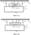
- FIG. 2 (a) is a schematic view of an example of a system according to an embodiment of the present invention.
- the system of FIG. 2 (a) corresponds to the system of FIG. 1 .
- the system of FIG. 2 (a) comprises an additional optional feature.
- a driver 203 for the light source 102 of the luminaire 100 may be arranged in the second housing 200.
- the driver 203 may be electrically connected with the light source, e.g. via an electrical line L2.
- the second housing 200 and the first housing 101 may comprise respective electrical connectors so that the driver 203 may be electrically connected to the light source 102, when the second housing 200 is arranged at the surface 101a of the first housing 101.
- the driver 203 may be electrically connected, e.g. via an electrical line L1, to an external electrical energy source, such as mains.
- the second housing 200 may comprise a respective electrical connector for being connected to an electrical line at the ceiling 300.
- the RF module 201 is part of the driver 203.
- FIG. 2 (b) is a schematic view of an example of a system according to an embodiment of the present invention.
- the system of FIG. 2 (b) corresponds to the system of FIG. 2 (a) , wherein the system of FIG. 2 (b) differs from the system of FIG. 2 (a) with regard to a driver arranged in the second housing of the system.
- a driver arranged in the second housing of the system.
- the driver 203 is electrically connected with the RF module 201. That is, the RF module 201 may be a separate element with regard to the driver 203.
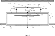
- FIG. 3 is a schematic view of an example of a system according to an embodiment of the present invention.
- the system of FIG. 3 corresponds to the system of FIG. 1 .
- the system of FIG. 3 comprises additional optional features and differs from the system of FIG. 1 in the type of luminaire.
- FIG. 1 for describing the system of FIG. 3 reference is made to the description with regard to FIG. 1 and in the following mainly the additional optional features of the system of FIG. 3 is described.
- the optional feature of FIG. 2 (a) or FIG. 2 (b) may optionally be implemented in the system of FIG. 3 .
- the luminaire 100 is a recessed luminaire for being installed in a space between a ceiling 300 and a suspended ceiling 400.
- the recessed luminaire 100 is shown in the installed state, i.e. it is arranged in the space between the ceiling 300 and the suspended ceiling 400.
- the type of luminaire may be differently, wherein the following description is correspondingly valid.
- one or more slot antennas 202a arranged in the first surface 200a of the second housing 200 allows a wireless communication by the RF module 201 in the space between the ceiling 300 and the suspended ceiling 400, e.g. with another entity 500 arranged in said space.
- the other entity 500 may be a control unit for controlling light emission of the luminaire 100 and optional one or more further luminaires; a sensor for providing information on the environment of the luminaire 100 (e.g. a temperature); a communication unit for connecting the RF module 201 and, thus, the luminaire 100 to a communication network etc.
- a wireless communication using radio waves in the space between the ceiling 300 and the suspended ceiling 400 has the advantage that it is not blocked or attenuated by objects present in a respective room comprising the suspended ceiling 400.
- this allows elements for controlling luminaires, providing information on the environment and/or connecting luminaires to a communication network to be placed in the aforementioned space and, thus, to hide such components from being seen by a person.
- This has an aesthetical advantage and a safety advantage, as a risk that normal persons manipulate components, which are hidden in the space between the ceiling 300 and the suspended ceiling 400, is small.
- the radio waves radiated by the RF module 201 may be radiated via the one or more slot antennas 202b to the outside of the second housing 200 in a direction towards the first housing 101.
- the radio waves travel through the first housing 101 and via the second surface 101b of the first housing 101 to the outside of the luminaire 100. This is indicated in FIG. 3 by the dashed arrow extending from the slot antenna 202b through the second surface 101b of the first housing 101.
- a part of the first housing 101, on which radio waves radiated by the one or more slot antennas 202b in a main radiation direction of the respective slot antenna impinge, may comprise an opening or may be made of a material (e.g. plastic) that allows radio waves to pass through (not shown in FIG. 3 ). This allows the radio waves radiated by the RF module 201 to travel through the first housing 101 in the direction of the second surface 101b of the first housing 101.
- a material e.g. plastic
- the first housing is made of a material (e.g. plastic) that allows radio waves to pass through (not shown in FIG. 3 ). This allows the radio waves radiated by the RF module 201 to travel through the first housing 101 in the direction of the second surface 101b of the first housing 101.
- a material e.g. plastic
- the first housing 101 may comprise in the surface 101a, on which the second housing 200 is arranged, one or more slot antennas such that the one or more slot antennas are configured to couple radio waves radiated by the one or more slot antennas 202b (arranged in the second surface 200b of the second housing 200) into the first housing 101 (not shown in FIG. 3 ).
- the aforementioned one or more optional slot antennas of the first housing 101 may be configured to direct the radio waves radiated by the one or more slot antennas 202b (arranged in the second surface 200b of the second housing 200) in a direction of the area A1 of the second surface 101b of the first housing 101, via which the light source 102 is configured to emit light.
- the light source 102 (e.g. comprising two or more lighting means, such as two or more LEDs) may be arranged on a printed circuit board 103 (PCB) in the first housing 101, the PCB 103 being substantially parallel to the surface 101a of the first housing 101, on which the second housing 200 is arranged.
- the PCB 103 may comprise a keep out area A2 for components comprising a material (e.g. metal) that does not allow radio waves to pass through.
- the keep out area A2 is an area of the PCB 103, through which radio waves radiated by the one or more slot antennas 202b (arranged in the second surface 200b of the second housing 200) in a main radiation direction of the respective slot antenna travel.
- FIG. 3 shows that the second housing 200 is arranged on the surface 101a of the first housing 101, wherein the surface 101a is an outer surface of the first housing 101. This is only a possible example.
- the second housing 200 may be arranged on the surface 101a of the first housing 101 being an inner surface of the first housing 101 (not shown in FIG. 1 ).
- the description of FIG. 3 is correspondingly valid.
- the radio waves radiated by the RF module 201 may be radiated via the one or more slot antennas 202a to the outside of the second housing 200 in a direction towards the surface 101a (inner surface) of the first housing 101.
- the radio waves travel through the first housing 101 to the outside of the luminaire 100. This allows a wireless communication by the RF module 201 in the space between the ceiling 300 and the suspended ceiling 400, e.g. with another entity 500 arranged in said space.
- a part of the first housing 101, on which radio waves radiated by the one or more slot antennas 202a in a main radiation direction of the respective slot antenna impinge, may comprise an opening or may be made of a material (e.g. plastic) that allows radio waves to pass through. This allows the radio waves radiated by the RF module 201 to travel through the first housing 101 to outside the luminaire 100, e.g. in the direction of another entity 500 arranged in the space between the ceiling 300 and the suspended ceiling 400.
- a material e.g. plastic
- the first housing is made of a material (e.g. plastic) that allows radio waves to pass through. This allows the radio waves radiated by the RF module 201 to travel through the first housing 101 to outside the luminaire 100, e.g. in the direction of another entity 500 arranged in the space between the ceiling 300 and the suspended ceiling 400.
- a material e.g. plastic
- the first housing 101 may comprise in the surface 101a, on which the second housing 200 is arranged, one or more slot antennas such that the one or more slot antennas are configured to couple radio waves radiated by the one or more slot antennas 202a (arranged in the first surface 200a of the second housing 200) out of the first housing 101 (not shown in FIG. 3 ).
- the aforementioned one or more optional slot antennas of the first housing 101 may be configured to direct the radio waves radiated by the one or more slot antennas 202a (arranged in the first surface 200a of the second housing 200) in a direction of the space between the ceiling 300 and the suspended ceiling 400, e.g. in a direction of another entity 500 arranged in said space.
- the radio waves radiated by the RF module 201 may be radiated via the one or more slot antennas 202b to the outside of the second housing 200 through the first housing 100 in a direction towards the second surface 101b of the first housing 101.
- the radio waves travel through the first housing 101 and via the second surface 101b of the first housing 101 to the outside of the luminaire 100.
- the second housing 200 may be arranged on a side surface 101c of the first housing 101 (not shown in FIG.3 ), the side surface 101c of the first housing 101 connecting the surface 101a and the second surface 101b of the first housing 101.
- the side surface 101c may be an inner surface or an outer surface of the first housing 101.
- FIG. 4 is a schematic view of an example of a system according to an embodiment of the present invention.
- the system of FIG. 4 corresponds to the system of FIG. 3 .
- the system of FIG. 4 differs from the system of FIG. 3 with regard to the implementation of the luminaire 100 of the system.
- FIG. 4 differs from the system of FIG. 3 with regard to the implementation of the luminaire 100 of the system.
- the PCB 103 may be interrupted in an area A3, through which radio waves radiated by the one or more slot antennas 202b (arranged in the second surface 200b of the second housing 200) in a main radiation direction of the respective slot antenna travel.
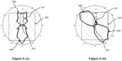
- FIG. 6 (a) is an example of a radiation pattern emittable by the RF module of a system according to an embodiment of the present invention.
- FIG. 6 (b) is an example of a radiation pattern emittable by the RF module of a system according to an embodiment of the present invention.
- FIGs. 6 (a) and 6 (b) may be any system of FIGs. 1 to 4 .
- FIGs. 6 (a) and 6 (b) a top view of the first housing 101 of the luminaire 100 and the second housing 200 having a slot antenna 202 in one of its surfaces is shown.
- FIG. 6 (a) and Figure 6 (b) differ from each other in that the orientation of the slot antenna 202 in the surface of the second housing 200 is different. That is, the slot antenna 202 of the second housing 200 shown in FIG. 6 (b) is tilted, e.g. by 45°, with regard to the slot antenna 202 of the second housing 200 shown in FIG. 6 (a) .
- FIGs. 6 (a) As may be derived from FIGs.
- the orientation of the slot antenna 202 of the second housing has an effect on the radiation pattern 600 radiated by the RF module 201 via the slot antenna 202 to outside the second housing 200.
- a beam shaping may be achieved by the slot antenna orientation.
- the effective radiation pattern of the RF module 201 perceived outside of the second housing 200 may depend on the number of slot antenna(s) 202 of the second housing, the arrangement of the slot antenna(s) 202 at the second housing 200, and the design (e.g. size, shape and/or orientation) of the slot antenna(s) 202 of the second housing 200.
- FIG. 7 is an example of a radiation pattern emittable by the RF module of a system according to an embodiment of the present invention.
- the system of FIG. 7 may be any system of FIGs. 1 to 4 .
- a side view of the first housing 101 of the luminaire 100 and the second housing 200 is shown.
- the second housing 200 comprises a slot antenna 202a in the second surface 200b of the second housing 200 facing the surface 101a of the first housing 101.
- this allows achieving a radiation pattern 600 in the direction of the first housing 101, i.e. towards the lower hemisphere, without strong blind spots regardless of the antenna type used by the RF module 201 for the radiation of radio waves.
- this allows achieving a radiation pattern 600 with a relatively evenly distributed radiation, e.g. compared to the radiation pattern shown in FIG. 5 .
- FIG. 8 (a) is an example of a radiation pattern emittable by the RF module of a system according to an embodiment of the present invention.
- the system of FIG. 8 (a) may be any system of FIGs. 1 to 4 .
- FIG. 8 (a) a side view of the first housing 101 of the luminaire 100 and the second housing 200 is shown.
- the second housing 200 comprises a slot antenna 202a in the second surface 200b of the second housing 200 facing the surface 101a of the first housing 101 and two slot antennas 202a in the first surface 200a of the second housing.
- FIG. 8 (a) is an example of a radiation pattern emittable by the RF module of a system according to an embodiment of the present invention.
- the system of FIG. 8 (a) may be any system of FIGs. 1 to 4 .
- FIG. 8 (a) a side view of the first housing 101 of the luminaire 100 and the second housing 200 is shown.
- the second housing 200 comprises a slot antenna 202a in the second surface 200b of the
- this allows achieving a radiation pattern 600 in the direction of the first housing 101 and in a direction away from the first housing 101, i.e. towards the lower hemisphere and upper hemisphere, without strong blind spots regardless of the antenna type used by the RF module 201 for the radiation of radio waves. In other words, this allows achieving a radiation pattern 600 with a relatively evenly distributed radiation, e.g. compared to the radiation pattern shown in FIG. 5 .
- FIG. 8 (b) is an example of a radiation pattern emittable by the RF module of a system according to an embodiment of the present invention.
- a side view of the first housing 101 of the luminaire 100 and the second housing 200 is shown.
- the second housing 200 comprises a slot antenna 202a in the second surface 200b of the second housing 200 facing the surface 101a of the first housing 101 and two slot antennas 202a in the first surface 200a of the second housing 200.
- this allows achieving a radiation pattern 600 in the direction of the first housing 101 and in a direction away from the first housing 101, i.e.
- FIGs. 8 (a) and 8 (b) shows that the design (e.g. size, shape and/or orientation) of the slot antennas of the second housing 200 and optional the arrangement of the slot antennas of the second housing 200 may change the effective radiation pattern 600 radiated by the RF module 201 and perceived outside the second housing 200.
- the second housing of the system especially the one or more slot antennas of the second housing, of the present invention allow customizing radiation patterns of the RF module arranged in the second housing with regard to desired radiation characteristics of the RF module. This may be done regardless of the type of RF module, e.g. regardless of the antenna type used by the RF module for radio wave radiation.
- the number of slot antennas described with regard to FIGs. 6 to 8 are only by way of example and may be differently for achieving a desired radiation pattern of radio waves outside the second housing.
Landscapes
- Engineering & Computer Science (AREA)
- General Engineering & Computer Science (AREA)
- Non-Portable Lighting Devices Or Systems Thereof (AREA)
Abstract
The present invention provides a system comprising a luminaire (100) that comprises a first housing (101) and a light source (102) arranged in the first housing (101), and a second housing (200), in which a radio frequency, RF, module (201) being packaged is arranged. The second housing (200) is arranged on a surface (101a) of the first housing (101), the surface (101a) being opposite to a second surface (101b) of the first housing (101) via which the light source (102) of the luminaire (100) is configured to emit light. The second housing (200) comprises one or more slot antennas (202). The RF module (201) is arranged in the second housing (200) such that the RF module (201) is configured to radiate radio waves via the one or more slot antennas (202) to an outside of the second housing (200).
Description
- The present invention relates to a system comprising a luminaire, which comprises a first housing and a light source, and a second housing, in which a radio frequency (RF) module being packaged is arranged. The present invention relates to a housing for a packaged RF module.
- Mounting RF modules or drivers with RF functionality on luminaires is a challenging task. A primary focus of the design and constructive elements of a luminaire is on the optical/thermal and aesthetic performance of the luminaire. No obstruction and no shadowing by an entity, such as the RF module, in the direct or indirect optical path of the luminaire is desired. No impact by an entity, such as the RF module, on reflective or spectral behavior is desired.
- Therefore, any driver for driving the light source of the luminaire is arranged at the luminaire such as not to interfere in any way with the optical path. Preferably, the driver is placed such that it is not directly visible from the outside.
- However, an arrangement of the RF module or driver with RF functionality not disturbing a direct or indirect optical paths of the luminaire may mean that any direct RF radiation is to a similar extent prevented to emerge from the RF module or driver with RF functionality to the outside of the luminaire.
- Additionally, in many cases the materials of constructive elements of a luminaire are made of metals. This again strongly impacts the performance and radiation properties of nearby RF modules, resulting in strong shadowing and obstacles in the desired RF path, undesired directivity and uneven radiation patterns.
- For protecting the RF module, the RF module may be arranged in a metal housing that is arranged on a surface of a housing of the luminaire that is opposite to a surface of the luminaire's housing via which light is emitted by the luminaire. This allows preventing an impact by the metal housing on the light emission of the luminaire.
FIG. 5 is an example of a radiation pattern emittable by a packaged RF module arranged in a metal housing, which is arranged on a housing of a luminaire. For allowing wireless communication by the RF module with an entity outside the metal housing the metal housing comprises at a part of the housing no metal. For example, this part of the housing may be made of a non-metal material, such as plastic, or this part may be an opening in the metal housing. Via this part of the metal housing radio waves may travel from inside the metal housing to outside and vice versa.FIG. 5 is a top view of a luminaire'shousing 101 and the metal housing 200', in which the RF module is arranged. As shown inFIG. 5 , theradiation pattern 600 that may be radiated by the RF module in such an arrangement has a strong directivity and there are large areas that are not covered by theradiation pattern 600. These areas may be referred to as blind spots. The antenna used by the RF module for the RF communication causes this strong directivity. For example, the antenna may be a monopole or dipole antenna. - Moreover, a metal housing having a part that is not made of metal is disadvantageous with regard to manufacturing the housing. When the metal house is fully made of metal using e.g. sheet metal, the sheet metal may be bended for forming the metal housing. When the metal housing comprises a part that does not comprise a metal, such as a part comprising a non-metal material or an opening, additional manufacturing steps are necessary which make the manufacturing more complex, time consuming and expensive.
- Therefore, it is an object of the present invention to provide a system comprising a luminaire and a RF module allowing an arrangement of the RF module at the luminaire such that there is no impact by the RF module on a light emission of the luminaire and allowing an improved wireless communication by the RF module. It is in particular an object of the present invention to provide a system comprising a luminaire and a RF module allowing an arrangement of the RF module at the luminaire such that the RF module is protected against environmental influences and an improved wireless communication by the RF module may be achieved.
- These and other objects, which become apparent upon reading the following description, are solved by the subject matter of the independent claim. The dependent claims refer to preferred embodiments of the invention.
- According to a first aspect of the invention, a system is provided. The system comprises a luminaire. The luminaire comprises a first housing and a light source arranged in the first housing. The system comprises a second housing, in which a radio frequency (RF) module being packaged is arranged. The second housing is arranged on a surface of the first housing, the surface being opposite to a second surface of the first housing via which the light source of the luminaire is configured to emit light. Alternatively, the second housing is arranged on a side surface of the first housing, the side surface of the first housing connecting the surface and the second surface of the first housing. The second housing comprises one or more slot antennas. The RF module is arranged in the second housing such that the RF module is configured to radiate radio waves via the one or more slot antennas to an outside of the second housing.
- In other words, the first aspect proposes a system with a luminaire comprising a first housing and with a second housing, in which a packaged RF module is arranged, wherein the second housing comprises one or more slot antennas. As a result, the second housing may function as a secondary antenna device for changing the radiation pattern initially radiated by the RF module to a desired radiation pattern.
- The surface of the first housing may be an inner surface or outer surface of the first housing. The term "inside surface" and "outside surface" may be used as synonyms for the terms "inner surface" and "outer surface", respectively. That is, when the second housing is arranged on the surface of the first housing being an outer surface of the first housing, then the second housing is arranged outside the first housing on the surface of the first housing. Accordingly, when the second housing is arranged on the surface of the first housing being an inner surface of the first housing, then the second housing is arranged inside the first housing on the surface of the first housing. This may apply to the side surface accordingly. That is, the side surface of the first housing may be an inner surface or outer surface of the first housing. The aforementioned may apply to the second surface accordingly. That is, the second surface of the first housing may be an inner surface or outer surface of the first housing
The one or more slot antennas allow the RF module to wirelessly communicate via the one or more slot antennas with outside the second housing. As a result, the second housing may be fully made of metal without the need of a part of the second housing being made of no metal. That is, the second housing may be a metal housing. Therefore, the second housing may be made of sheet metal and, thus, may be easily manufactured by bending the sheet metal. - Moreover, the one or more slot antennas of the second housing may change a radiation pattern radiated by the RF module. As a result, the one or more slot antennas may extend a spatial radiation pattern of the RF module, which may be limited to one or several spatial directions by the antenna type (e.g. monopole or dipole antenna) used by the RF module for wireless communication, by one or more further additional spatial directions. This allows increasing a spatial range of RF communication by the RF module with the outside of the second housing.
- Moreover, this may be achieved regardless of the antenna type used by the RF module as the effective radiation pattern (initially caused by the RF module) and, thus effective spatial range of the RF communication by the RF module, as perceived outside the second housing, depends on the number, arrangement at the second housing and design (e.g. size, shape and/or orientation) of the one or more slot antennas of the second housing. In other words, the radiation of the radio waves by the RF module to outside a housing, in which the RF module is arranged, is not anymore only depend on the antenna type used by the RF module. It depends on the number, arrangement at the second housing and design (e.g. size, shape and/or orientation) of the one or more slot antennas of the second housing. Thus, the second housing allows achieving a radiation pattern or radiation characteristics that is/are independent of the radiation pattern or radiation characteristics of the RF module. The second housing allows achieving a desired radiation characteristic and desired radiation direction of radio waves radiated by the RF module independent of the RF module type.
- The one or more slot antennas may be configured to amplify a radio signal radiated in the form of radio waves by the RF module. In addition or alternatively, the one or more slot antennas may be configured to direct the radio signal radiated in the form of radio waves by the RF module in one or more directions. In other words, the one or more slot antennas may be configured to change one or more characteristics of a radiation pattern radiated by the RF module. That is, the one or more slot antennas may be configured to change the radiation characteristic of the RF module.
- For example, in case the antenna used by the RF module is a monopole or dipole antenna, a radiation pattern of such antennas comprises areas (may be referred to as blind spots), in which no radio waves are radiated. The one or more slot antennas of the second housing allow covering such blind spots by changing the radiation pattern of the RF module, accordingly.
- A further advantage of the system according to the first aspect is that the RF module may be arranged more flexible in the second housing. This is advantageous in case there are additional components arranged in the second housing, such as one or more drivers for the light source of the luminaire, one or more sensor for providing information on the environment of the luminaire (e.g. temperature, ambient light etc.), one or more electrical energy storages (e.g. one or more batteries, optionally rechargeable) etc. The more flexible arrangement is due to the following: It is sufficient for a wireless communication with an entity outside the second housing that the one or more slot antennas of the second housing are configured to re-transmit or forward (i.e. receive and transmit) the radio waves radiated by the RF module when the RF module is arranged at its installation position in the second housing. For this, the second housing may be accordingly designed, i.e. a number and position of the one or more slot antennas in the second housing and design (e.g. size, shape and/or orientation) of the one or more slot antennas is selected accordingly.
- In contrast thereto, in a conventional housing for a RF module comprising a part made of no metal, the RF module needs to be arranged such that radio waves radiated by the RF module travel in the direction of the aforementioned part of no metal. As a result, the arrangement of the RF module in such a conventional housing is limited. Further, the system according to the first aspect allows besides a flexible arrangement of the RF module in the second housing also a more flexible design of the shape of the second housing.
- Moreover, for achieving a desired radiation pattern of radio waves for a desired wireless communication with an entity outside the luminaire, the system of the first aspect allows using different types of RF modules. Namely, as outlined already above, the one or more slot antennas may change the initial radiation pattern of radio waves radiated by the RF module to achieve the desired radiation pattern outside the second housing and outside the luminaire. It is sufficient that the radio waves radiated by the RF module reach the one or more slot antennas, i.e. travel inside the second housing to the one or more slot antennas. Several types of RF modules may achieve this. In contrast thereto, in a conventional housing for a RF module, merely comprising a part that is not made of metal, the radiation pattern for the wireless communication outside the housing and outside the luminaire is merely determined by the type of RF module. Therefore, it is not possible using in a conventional housing for a packaged RF module different types of RF modules. Namely, changing the RF module type changes the radiation pattern of the RF module encountered outside the conventional housing.
- Moreover, the system of the first aspect has the advantages that the one or more slot antennas of the second housing may compensate influences of a metal material of the second housing on a matched high frequency circuit of the RF module.
- In addition, the arrangement of the RF module is more flexible with regard to an orientation of the RF module. Namely, an initial direction of radio waves radiated by the RF module (e.g. due to its antenna type and orientation) may be changed by the one or more slot antennas of the second housing, as outlined already above.
- The RF module being packed means that the RF module comprises its own housing, which may be referred to as module housing. That is, the components of the RF module (e.g. one or more antennas, electrical circuit(s) etc.) are enclosed in the module housing. The RF module may be referred to as "packed RF module". Thus, the second housing is not a packaging of the RF module. The radio RF module may be packaged in a packaging, which is arranged inside the second housing. Since the RF module is arranged in the second housing, the second housing encloses the RF module. The second housing may be referred to as "RF antenna housing". The RF module may be packaged according to any means known in the art. The RF module may comprise one or more antennas for wireless communication using radio waves. For example, the RF module may comprise one or more monopole antennas and/or one or more dipole antennas.
- The RF module being configured to radiate radio waves via the one or more slot antennas to the outside of the second housing means that the RF module is configured to wirelessly communicate to the outside of the second housing using the one or more slot antennas of the second housing. Correspondingly, the RF module may be configured to receive radio waves via the one or more slot antennas from the outside of the second housing. That is, the RF module and the one or more slot antennas of the second housing may be electromagnetically coupled so that the RF module may wirelessly communicate via the one or more slot antennas. In other words, the RF module may be arranged in the second housing such that the RF module is configured to wirelessly communicate via the one or more slot antennas with the outside of the second housing, e.g. with an entity arranged outside the second housing. That is, each of the one or more slot antennas is configured to receive radio waves radiated by the RF module and radiate the received radio waves in a direction and with a radiation pattern defined by the design (e.g. size, shape and/or orientation) of the respective slot antenna and by the arrangement of the respective slot antenna in the surface of the second housing. A description herein with regard to a radiation of radio waves by the RF module via the one or more slot antennas is correspondingly valid with regard to the RF module being configured to receive radio waves via the one or more slot antennas from outside the second housing. In other words, the RF module may be configured to receive radio waves via the one or more slot antennas from outside the second housing.
- Since the light source is arranged in the first housing, the first housing encloses the light source. The light source may comprise one or more types of lighting means. For example, the light source may comprise one or more light emitting diodes (LEDs). The present invention is not limited to a specific type of light source.
- The second surface of the first housing may be referred to as "light emitting surface" of the first housing. The first housing represent the luminaire's housing. The surface of the first housing, on which the second housing may be arranged, may be referred to as "back" or "back side" of the first housing or luminaire, and the second surface of the first housing may be referred to as "front" or "front side" of the first housing or luminaire.
- The second housing may be mounted to the first housing by any means known in the art. For example, the second housing may be mounted by at least one of a form-fit, a force-locking and adhesive connection to the first housing. The second housing may be removably mounted to the first housing.
- The one or more slot antennas of the second housing may be formed in one or more surfaces of the second housing. The part of the second housing, where a slot antenna is formed, is made of metal. The second housing may be a metal housing.
- At least one slot antenna of the one or more slot antennas of the second housing is arranged in one or more of: a first surface of the second housing that is opposite to a second surface of the second housing facing the surface of the first housing or the side surface of the first housing, on which the second housing is arranged; the second surface of the second housing; and one or more side surfaces of the second housing connecting the first surface and second surface of the second housing.
- Any surface of the second housing may be an inner surface or an outer surface. A slot antenna being arranged in a housing wall forming surfaces of a housing, such as the second housing, may be formed by a slot in the housing wall and will be referenced by the respective surface formed by the housing. The slot may be a passage between the outside and inside of the housing. The term "opening" may be used as a synonym for the term "passage".
- The side surface may be integrally formed with the first surface and/or the second surface of the second housing. An angle may exist between the side surface and the first surface. An angle may exist between the side surface and the second surface. The aforementioned may be correspondingly valid for a side surface of the first housing.
- One or more slot antennas being arranged in the first surface of the second housing has the advantage that radio waves radiated by the RF module may be radiated via the aforementioned one or more slot antennas in a direction away from the first housing. For example, in case the luminaire is a recessed luminaire for being installed in a space between a ceiling and a suspended ceiling, the aforementioned one or more slot antennas allow a radiation of radio waves by the RF module into the space between the ceiling and the suspended ceiling, when the luminaire is installed. This allows a wireless communication in such a space. In case the luminaire is a suspension luminaire, this allows a wireless communication In the direction of a ceiling at which the suspended luminaire may be installed.
- In case the second housing is arranged inside the first housing, the first housing may be made of a material, which that allows radio waves to pass through, at least at a part of the first housing at which radio waves radiated by the at least one slot antenna of the second housing imping. This allows the radio waves to be radiated outside the first housing.
- Optionally, the one or more slot antennas being arranged in the first surface of the second housing may be arranged at a center of the first surface of the second housing. This allows a more homogenous radiation pattern compared to a case where the one or more slot antennas are arranged in the first surface closer to a side surface of the second housing. In addition, the radiation efficiency may be better.
- One or more slot antennas being arranged in the second surface of the second housing has the advantage that radio waves radiated by the RF module may be radiated via the aforementioned one or more slot antennas in a direction towards the first housing and, thus, through the first housing towards the second surface of the first housing. This allows a radiation of radio waves radiated by the RF module in a direction of light emission of the luminaire. For example, the luminaire may be a suspension luminaire or a surface-mounted luminaire installed at a ceiling such that the second surface of the first housing faces ground (i.e. facing in the opposite direction with regard to a direction towards the ceiling). In this case, the aforementioned one or more slot antennas of the second housing allow a radiation of radio waves by the RF module in the direction of the ground. This is correspondingly valid in case the luminaire is a recessed luminaire installed in a space between a ceiling and a suspended ceiling.
- Optionally, the one or more slot antennas being arranged in the second surface of the second housing may be arranged at a center of the second surface of the second housing. This allows a more homogenous radiation pattern compared to a case where the one or more slot antennas are arranged in the second surface closer to a side surface of the second housing. In addition, the radiation efficiency may be better.
- One or more slot antennas being arranged in one or more side surfaces of the second housing has the advantage that radio waves radiated by the RF module may be radiated via the aforementioned one or more slot antennas sideward of the luminaire. For example, in case the luminaire is a suspension luminaire, the aforementioned one or more slot antennas of the second housing allow a sideward radiation of radio waves by the RF module when the luminaire is installed. This allows a communication of two such luminaires with each other that are roughly installed at the same height next to each other. The aforementioned is correspondingly true for a different type of luminaire, such as a recessed for being installed in a space between a ceiling and a suspended ceiling, or a surface-mounted luminaire.
- Optionally, the second housing has a cuboidal shape or cylindrical shape.
- Optionally, a distance between two opposing inner surfaces of the second housing is a multiple of half a wave-length of the radio waves that the RF module is configured to radiate.
- That is, the dimensions of the second housing may depend on the frequency of the radio waves that may be radiated by the RF module. In other words, the second housing may be a waveguide. This allows the radio waves radiated by the RF module to be guided to the one or more slot antennas of the second housing in order to be retransmitted or forwarded by the one or more slot antennas to the outside of the second housing. The aforementioned retransmission or forwarding of the radio waves depends on the design (e.g. size, shape and/or orientation) of the one or more slot antennas and position of the one or more slot antennas at the second housing.
- The dimensions of the second housing may be designed such that there is an electromagnetically coupling between the RF module and the one or more slot antennas of the housing allowing the RF module to wirelessly communicated using radio waves via the one or more slot antennas with outside the second housing. The cross section of the second housing may depend on the frequency of the radio waves that may be radiated by the RF module. The second housing, e.g. the cross section of the second housing, may be designed such that the second housing represents a waveguide for the radio waves radiated by the RF module.
- A driver for the light source of the luminaire may be arranged in the second housing and is electrically connected with the light source of the luminaire. The driver may be electrically connected to the RF module. Alternatively, the RF module may be part of the driver.
- The driver for driving the light source (i.e. for electrically supplying and, thus, controlling light emission by the light source) may be implemented according to any means known in the art.
- Optionally, the light source comprises one or more LEDs and the driver is a LED driver.
- The luminaire may be a recessed luminaire for being installed in a space between a ceiling and a suspended ceiling, a suspension luminaire or a surface-mounted luminaire. Optionally, the luminaire may be a high-bay luminaire.
- The system is not limited to a specific type of luminaire.
- Optionally, at least one slot antenna of the one or more slot antennas of the second housing is arranged in a surface of the second housing facing the surface of the first housing or the side surface of the first housing, on which the second housing is arranged. A part of the first housing, on which radio waves radiated by the at least one slot antenna in a main radiation direction of the slot antenna impinge, may comprise an opening or may be made of a material that allows radio waves to pass through.
- This allows the radio waves radiated by the RF module to travel through the first housing in the direction of the second surface of the first housing, via which the light source is configured to emit light. Therefore, the radio waves may travel via the second surface (light emission surface) of the first housing to the outside of the first housing and, thus, the outside of the luminaire. Namely, the part of the first housing, via which light is emitted by the light source allows radio waves to pass through. That is, such a part comprises an opening or is made of a material allowing light to pass through so that such a part allows radio waves to pass through.
- Optionally, at least one slot antenna of the one or more slot antennas of the second housing is arranged in a surface of the second housing facing the surface of the first housing or the side surface of the first housing, on which the second housing is arranged, and the first housing is made of a material that allows radio waves to pass through.
- This allows the radio waves radiated by the RF module to travel through the first housing in the direction of the second surface of the first housing, via which the light source is configured to emit light. Therefore, the radio waves may travel via the second surface (light emission surface) of the first housing to the outside of the first housing and, thus, the outside of the luminaire. A material that allows radio waves to pass through may be for example plastic.
- Optionally, at least one slot antenna of the one or more slot antennas of the second housing is arranged in a surface of the second housing facing the surface of the first housing or the side surface of the first housing, on which the second housing is arranged. The first housing may comprise in the surface or the side surface, on which the second housing is arranged, one or more slot antennas such that the one or more slot antennas are configured to couple radio waves radiated by the at least one slot antenna into the first housing or out of the first housing.
- For example, when the second housing is arranged on the surface of the first housing being an outer surface, then the first housing may comprise in the surface, on which the second housing is arranged, one or more slot antennas such that the one or more slot antennas are configured to couple radio waves radiated by the at least one slot antenna of the second housing into the first housing.
- For example, when the second housing is arranged on the surface of the first housing being an inner surface, then the first housing may comprise in the surface, on which the second housing is arranged, one or more slot antennas such that the one or more slot antennas are configured to couple radio waves radiated by the at least one slot antenna of the second housing out of the first housing.
- For example, when the second housing is arranged on the side surface of the first housing being an outer surface, then the first housing may comprise in the side surface, on which the second housing is arranged, one or more slot antennas such that the one or more slot antennas are configured to couple radio waves radiated by the at least one slot antenna of the second housing into the first housing. In this case, one or more directing and/or guiding elements, such as a waveguide, may be present inside the second housing. The one or more directing and/or guiding elements are configured to direct and optionally guide the radio waves coupled by the one or more slot antennas of the side surface of the first housing into the first housing towards the second surface of the first housing. This allows the radio waves to travel from inside the first housing via the second surface of the first housing to the outside of the first housing.
- For example, when the second housing is arranged on the side surface of the first housing being an inner surface, then the first housing may comprise in the side surface, on which the second housing is arranged, one or more slot antennas such that the one or more slot antennas are configured to couple radio waves radiated by the at least one slot antenna of the second housing out of the first housing.
- This allows the first housing of the luminaire to be made of metal. Namely, although metal prevents radio waves to pass through it, the aforementioned one or more slot antennas of the first housing allow radio waves radiated by the RF module to travel through the first housing in the direction of the second surface of the first housing, via which the light source is configured to emit light. Therefore, the radio waves may travel via the second surface (light emission surface) of the first housing to the outside of the first housing and, thus, the outside of the luminaire.
- The one or more slot antennas of the first housing may be configured to amplify a radio signal radiated in the form of radio waves by the RF module.
- Optionally, the one or more slot antennas of the first housing are configured to direct the radio waves radiated by the at least one slot antenna in a direction of an area of the second surface of the first housing, via which the light source is configured to emit light.
- This allows coupling the radio waves out of the first housing to an outside of the luminaire. The area may comprise an opening for light emission. The area may be made of material through which light may pass. This area may be such that a person may see through it or not. The first housing may comprise an optic arrangement in the area. An optic arrangement may be arranged on the second surface in the aforementioned area.
- Optionally, at least one slot antenna of the one or more slot antennas of the second housing is arranged in a surface of the second housing facing the surface of the first housing, on which the second housing is arranged. The light source may be arranged on a printed circuit board, PCB, in the first housing, the PCB being substantially parallel to the surface of the first housing, on which the second housing is arranged. The PCB may be interrupted in an area, through which radio waves radiated by the at least one slot antenna of the second housing in a main radiation direction of the slot antenna travel. The surface of the first housing, on which the second housing is arranged, may be an outer surface of the first housing.
- This allows ensuring that radio waves radiated by the RF module are not blocked or extenuated by the components of the luminaire for light emission, i.e. by the light source of the luminaire and the PCB, on which the light source is arranged. The PCB may be parallel to the surface of the first housing, on which the second housing is arranged.
- Optionally, at least one slot antenna of the one or more slot antennas of the second housing is arranged in a surface of the second housing that is opposite to a surface of the second housing facing the surface of the first housing, on which the second housing is arranged. The light source may be arranged on a printed circuit board, PCB, in the first housing, the PCB being substantially parallel to the surface of the first housing, on which the second housing is arranged. The PCB may be interrupted in an area, through which radio waves radiated by the at least one slot antenna of the second housing in a main radiation direction of the slot antenna travel. The surface of the first housing, on which the second housing is arranged, may be an inner surface of the first housing.
- This allows ensuring that radio waves radiated by the RF module are not blocked or extenuated by the components of the luminaire for light emission, i.e. by the light source of the luminaire and the PCB, on which the light source is arranged.
- Optionally, at least one slot antenna of the one or more slot antennas of the second housing is arranged in a surface of the second housing facing the surface of the first housing, on which the second housing is arranged. The light source may be arranged on a printed circuit board, PCB, in the first housing, the PCB being substantially parallel to the surface of the first housing, on which the second housing is arranged. The PCB may comprise a keep out area for components comprising a material that does not allow radio waves to pass through, the keep out area being an area of the PCB, through which radio waves radiated by the at least one slot antenna of the second housing in a main radiation direction of the slot antenna travel. The surface of the first housing, on which the second housing is arranged, may be an outer surface of the first housing.
- This allows ensuring that radio waves radiated by the RF module are not blocked or extenuated by the components of the luminaire for light emission, i.e. by the light source of the luminaire and the PCB, on which the light source is arranged. The PCB may be parallel to the surface of the first housing, on which the second housing is arranged. For example, in case the PCB is a composite epoxy material (CEM) PCB or a FR-4 PCB, no copper traces may be arranged in the keep out area. For example, in case the PCB is a metal PCB the keep out region may comprise or be a dedicated cut out in the PCB.
- Optionally, at least one slot antenna of the one or more slot antennas of the second housing is arranged in a surface of the second housing that is opposite a surface of the second housing facing the surface of the first housing, on which the second housing is arranged. The light source may be arranged on a printed circuit board, PCB, in the first housing, the PCB being substantially parallel to the surface of the first housing, on which the second housing is arranged. The PCB may comprise a keep out area for components comprising a material that does not allow radio waves to pass through, the keep out area being an area of the PCB, through which radio waves radiated by the at least one slot antenna of the second housing in a main radiation direction of the slot antenna travel. The surface of the first housing, on which the second housing is arranged, may be an inner surface of the first housing.
- This allows ensuring that radio waves radiated by the RF module are not blocked or extenuated by the components of the luminaire for light emission, i.e. by the light source of the luminaire and the PCB, on which the light source is arranged.
- Optionally, the second housing is partly made of metal.
- At least a part of the housing where the one or more slot antennas are present may be made of metal. The housing may be a metal housing.
- In order to achieve the system according to the first aspect of the present invention, some or all of the above-described optional features may be combined with each other.
- According to a second aspect of the present invention a housing for a packaged radio-frequency (RF) module is provided. The housing is configured to be arranged on a surface of a housing of a luminaire. The housing comprises one or more slot antennas. The housing is adapted for arranging the packaged RF module in the housing such that the packaged RF module is configured to radiate radio waves via the one or more slot antennas to an outside of the housing when the packaged RF module is arranged in the housing.
- The above description with regard to the system according to the first aspect of the present invention is correspondingly valid for the housing according to the second aspect of the present invention. Especially, the description with regard to the first housing, the second housing, the RF module and the luminaire of the system according to the first aspect is correspondingly valid for the housing of the luminaire (on which the housing of the second aspect is configured to be arranged), the housing according to the second aspect, the packaged RF module and the luminaire (on which the housing of the second aspect is configured to be arranged), respectively. The description with regard to the housing according to the second aspect of the present invention is correspondingly valid for the system according to the first aspect of the present invention.
- The housing according to the second aspect achieves the same advantages as the system according to the first aspect.
- In order to achieve the housing according to the second aspect of the present invention, some or all of the above-described optional features may be combined with each other.
- All steps which are performed by the various entities described in the present application as well as the functionalities described to be performed by the various entities are intended to mean that the respective entity is adapted to or configured to perform the respective steps and functionalities.
- In the following, the invention is described exemplarily with reference to the enclosed figures (FIGs.), in which
- FIG. 1
- is a schematic view of an example of a system according to an embodiment of the present invention and an example of a housing for a packaged radio frequency (RF) module according to an embodiment of the present invention;
- FIG. 2 (a)
- is a schematic view of an example of a system according to an embodiment of the present invention;
- FIG. 2 (b)
- is a schematic view of an example of a system according to an embodiment of the present invention;
- FIG. 3
- is a schematic view of an example of a system according to an embodiment of the present invention; and
- FIG. 4
- is a schematic view of an example of a system according to an embodiment of the present invention.
- FIG. 5
- is an example of a radiation pattern emittable by a packaged radio frequency (RF) module arranged in a metal housing, which is arranged on a housing of a luminaire;
- FIG. 6 (a)
- is an example of a radiation pattern emittable by the RF module of a system according to an embodiment of the present invention;
- FIG. 6 (b)
- is an example of a radiation pattern emittable by the RF module of a system according to an embodiment of the present invention;
- FIG. 7
- is an example of a radiation pattern emittable by the RF module of a system according to an embodiment of the present invention;
- FIG. 8 (a)
- is an example of a radiation pattern emittable by the RF module of a system according to an embodiment of the present invention; and
- FIG. 8 (b)
- is an example of a radiation pattern emittable by the RF module of a system according to an embodiment of the present invention.
- In the figures (FIGs), corresponding elements have the same reference signs. The proportions and dimensions of the elements shown in the FIGs. do not represent the elements of the system to scale, but are merely chosen to describe the structure and function of the system.
-
FIG. 1 is a schematic view of an example of a system according to an embodiment of the present invention and an example of a housing for a packaged radio frequency (RF) module according to an embodiment of the present invention. The system ofFIG. 1 is an example of the system according to the first aspect of the present invention. The description of the system according to the first aspect is correspondingly valid for the system ofFIG. 1 . Thehousing 200 ofFIG. 1 for a packagedRF module 201 is an example of the housing according to the second aspect of the present invention. The description of the housing according to the second aspect is correspondingly valid for thehousing 200 ofFIG. 1 . - As shown in
FIG. 1 , the system comprises aluminaire 100, wherein theluminaire 100 comprises afirst housing 101 and alight source 102 arranged in thefirst housing 101. According to the example ofFIG. 1 , theluminaire 100 is a suspension luminaire. For example, thefirst housing 101 of theluminaire 100 may be mounted via suspension means 103 to aceiling 300, as shown inFIG. 1 . The present invention is not limited to theluminaire 100 being a suspension luminaire. Thus, theluminaire 100 may be any other luminaire type and the following description is correspondingly valid. - The system comprises a
second housing 200, in which a radio frequency (RF)module 201 being packaged is arranged. Thesecond housing 200 is arranged on asurface 101a of thefirst housing 101, thesurface 101a being opposite to asecond surface 101b of thefirst housing 101 via which thelight source 102 of theluminaire 100 is configured to emit light. As shown inFIG. 1 , thesecond surface 101b of thefirst housing 101 comprises an area A1, via which thelight source 102 is configured to emit light. In addition, side surfaces 101c of thefirst housing 101 connecting thesurface 101a andsecond surface 101b of thehousing 101 are indicated inFIG. 1 . Optionally, one or both of the side surfaces 101c may be integrally formed with thesurface 101a and/or thesecond surface 101b of thefirst housing 101. - The area A1 of the
second surface 101b of thefirst housing 101 may comprise an opening for light emission (not shown inFIG. 1 ). The area A1 may be made of material through which light may pass. Optionally, thefirst housing 101 may comprise an optic arrangement in the area A1. An optic arrangement may be arranged on thesecond surface 101b in the aforementioned area A1 (not shown inFIG. 1 ). Thefirst housing 101 and, thus, thesecond surface 101b and the area A1 thereof may be implemented according to any means known in the art for providing a housing of a luminaire. - The
second housing 200 comprises one ormore slot antennas 202. TheRF module 201 is arranged in thesecond housing 200 such that theRF module 201 is configured to radiate radio waves via the one ormore slot antennas 202 to an outside of thesecond housing 200. According to the example ofFIG. 1 , the second housing comprisesmultiple slot antennas 202. The number ofslot antennas 202 shown inFIG. 1 is only by way of example and may be different. - As shown in
FIG. 1 , thesecond housing 200 may comprise a slot antenna 202a in afirst surface 200a of thesecond housing 200 that is opposite to asecond surface 200b of thesecond housing 200 facing thesurface 101a of thefirst housing 101. This slot antenna 202a allows a radiation of radio waves radiated by theRF module 201 to the outside of thesecond housing 200 in a direction that is opposite to the first housing 101 (as indicated inFIG. 1 by the respective dashed arrow extending from theRF module 201 to the aforementioned slot antenna 202a). Optionally, thesecond housing 200 may comprise multiple of the aforementioned slot antenna 202a. - In addition or alternatively, the
second housing 200 may comprise a slot antenna 202b in thesecond surface 200b of thesecond housing 200 facing thesurface 101a of thefirst housing 101. This slot antenna 202b allows a radiation of radio waves radiated by theRF module 201 to the outside of thesecond housing 200 in a direction towards the first housing 101 (as indicated inFIG. 1 by the respective dashed arrow extending from theRF module 201 to the aforementioned slot antenna 202b). Optionally, thesecond housing 200 may comprise multiple of the aforementioned slot antenna 202b. - In addition or alternatively, the
second housing 200 may comprise a slot antenna 202c, 202d in one ormore side surfaces second housing 200 connecting thefirst surface 200a andsecond surface 200b of thesecond housing 200. Optionally, thesecond housing 200 may comprise multiple of the aforementioned slot antenna 202c, 202d in therespective side surface FIG. 1 , there is a slot antenna 202c in theleft side surface 200c of thesecond housing 200 and a slot antenna 202d in theright side surface 200d of thesecond housing 200. This is only by way of example and may be differently. The aforementioned slot antenna 202c or 202d allows a radiation of radio waves radiated by theRF module 201 to the outside of thesecond housing 200 in a direction sideward to thesecond housing 200. For example, the slot antenna 202c in theleft side surface 200c of thesecond housing 200 allows a radiation of radio waves radiated by theRF module 201 to the outside of thesecond housing 200 in a direction towards the left of thesecond housing 200. This is indicated inFIG. 1 by the respective dashed arrow extending from theRF module 201 to the aforementioned slot antenna 202c. The slot antenna 202d in theright side surface 200d of thesecond housing 200 allows a radiation of radio waves radiated by theRF module 201 to the outside of the second housing 200in a direction towards the right of thesecond housing 200. This is indicated inFIG. 1 by the respective dashed arrow extending from theRF module 201 to the aforementioned slot antenna 202d). At least one of the side surfaces 202c and 202d may be integrally formed with thefirst surface 200a and/or thesecond surface 200b of thesecond housing 200. - In the light of the above, the system of
FIG. 1 , especially thesecond housing 200, allows a radiation of radio waves radiated by theRF module 201 via the one ormore slot antennas 202 of thesecond housing 200 in one or more different directions and independent of the RF module type (e.g. the type of antenna used by the RF module 201). That is, the one ormore slot antennas 202 may change the radiation pattern of radio waves radiated by theRF module 201. For example, the one ormore slot antennas 202 may be configured to amplify the radio signal transmitted by theRF module 201. The effective radiation pattern of the RF module, perceived outside thesecond housing 200, depends on the number ofslot antennas 202, the design (e.g. size, shape and/or orientation) of the slot antenna(s) 202 and the arrangement of the slot antenna(s) 202 of thesecond housing 200 at thesecond housing 200. - According to the example of
FIG. 1 , thesurface 101a of thefirst housing 101, on which thesecond housing 200 is arranged, is an outer surface of thefirst housing 101. That is thesecond housing 200 is arranged outside thefirst housing 100. This is only a possible example. - According to another optional implementation, the
surface 101a of thefirst housing 101, on which thesecond housing 200 is arranged, may be an inner surface of the first housing 101 (not shown inFIG. 1 ). That is, thesecond housing 200 may be arranged inside thefirst housing 100. Since thesecond housing 200 may be arranged on thesurface 101a being an inner surface of thefirst housing 101, it may be arranged on a side of thelight source 102, at which it does not disturb light emission by thelight source 102. That is, it may be arranged at a back side of thelight source 102. The above description ofFIG. 1 is correspondingly valid in case thesurface 101a of thefirst housing 101, on which thesecond housing 200 is arranged, is an inner surface of thefirst housing 101. - According to another optional implementation, the
second housing 200 may be arranged on aside surface 101c of the first housing 101 (not shown inFIG. 1 ), theside surface 101c of thefirst housing 101 connecting thesurface 101a and thesecond surface 101b of thefirst housing 101. In this optional case, theside surface 101c may be an inner surface or an outer surface of thefirst housing 101. The above description ofFIG. 1 is correspondingly valid in case thesecond housing 200 is arranged on aside surface 101c of thefirst housing 101. - The shape of the
first housing 101 and the shape of thesecond housing 200 shown inFigure 1 is only by way of example and, thus, may be differently. The description ofFIG. 1 is correspondingly valid for the aforementioned cases. - For further information on the system of
FIG. 1 reference is made to the description of the system of the first aspect and the housing of the second aspect as well as to the description of the followingFIGs. 2 to 4 and6 to 8 . -
FIG. 2 (a) is a schematic view of an example of a system according to an embodiment of the present invention. The system ofFIG. 2 (a) corresponds to the system ofFIG. 1 . The system ofFIG. 2 (a) comprises an additional optional feature. Thus, for describing the system ofFIG. 2 (a) reference is made to the description with regard toFIG. 1 and in the following mainly the additional optional feature of the system ofFIG. 2 (a) is described. - As shown in
FIG. 2 (a) , adriver 203 for thelight source 102 of theluminaire 100 may be arranged in thesecond housing 200. Thedriver 203 may be electrically connected with the light source, e.g. via an electrical line L2. For this, thesecond housing 200 and thefirst housing 101 may comprise respective electrical connectors so that thedriver 203 may be electrically connected to thelight source 102, when thesecond housing 200 is arranged at thesurface 101a of thefirst housing 101. As shown inFIG. 2 (a) thedriver 203 may be electrically connected, e.g. via an electrical line L1, to an external electrical energy source, such as mains. For this, thesecond housing 200 may comprise a respective electrical connector for being connected to an electrical line at theceiling 300. According to the example ofFIG. 2 (a) , theRF module 201 is part of thedriver 203. -
FIG. 2 (b) is a schematic view of an example of a system according to an embodiment of the present invention. The system ofFIG. 2 (b) corresponds to the system ofFIG. 2 (a) , wherein the system ofFIG. 2 (b) differs from the system ofFIG. 2 (a) with regard to a driver arranged in the second housing of the system. Thus, for describing the system ofFIG. 2 (b) reference is made to the description with regard toFIG. 2 (a) and in the following mainly the difference of the system ofFIG. 2 (b) with regard to the system ofFIG. 2 (a) is described. - According to the example of
FIG. 2 (b) , thedriver 203 is electrically connected with theRF module 201. That is, theRF module 201 may be a separate element with regard to thedriver 203. -
FIG. 3 is a schematic view of an example of a system according to an embodiment of the present invention. The system ofFIG. 3 corresponds to the system ofFIG. 1 . The system ofFIG. 3 comprises additional optional features and differs from the system ofFIG. 1 in the type of luminaire. Thus, for describing the system ofFIG. 3 reference is made to the description with regard toFIG. 1 and in the following mainly the additional optional features of the system ofFIG. 3 is described. The optional feature ofFIG. 2 (a) or FIG. 2 (b) may optionally be implemented in the system ofFIG. 3 . - As shown in
FIG. 3 , theluminaire 100 is a recessed luminaire for being installed in a space between aceiling 300 and a suspendedceiling 400. InFIG. 3 , the recessedluminaire 100 is shown in the installed state, i.e. it is arranged in the space between theceiling 300 and the suspendedceiling 400. The type of luminaire may be differently, wherein the following description is correspondingly valid. - As indicated in
Figure 3 , one or more slot antennas 202a arranged in thefirst surface 200a of thesecond housing 200 allows a wireless communication by theRF module 201 in the space between theceiling 300 and the suspendedceiling 400, e.g. with anotherentity 500 arranged in said space. This is indicated inFIG. 3 by the dashed arrow extending from the slot antenna 202a to theother entity 500. For example, theother entity 500 may be a control unit for controlling light emission of theluminaire 100 and optional one or more further luminaires; a sensor for providing information on the environment of the luminaire 100 (e.g. a temperature); a communication unit for connecting theRF module 201 and, thus, theluminaire 100 to a communication network etc. A wireless communication using radio waves in the space between theceiling 300 and the suspendedceiling 400 has the advantage that it is not blocked or attenuated by objects present in a respective room comprising the suspendedceiling 400. In addition, this allows elements for controlling luminaires, providing information on the environment and/or connecting luminaires to a communication network to be placed in the aforementioned space and, thus, to hide such components from being seen by a person. This has an aesthetical advantage and a safety advantage, as a risk that normal persons manipulate components, which are hidden in the space between theceiling 300 and the suspendedceiling 400, is small. - As shown in
FIG. 3 , when thesecond housing 200 comprises one or more slot antennas 202b in thesecond surface 200b of thesecond housing 200, the radio waves radiated by theRF module 201 may be radiated via the one or more slot antennas 202b to the outside of thesecond housing 200 in a direction towards thefirst housing 101. In this case, the radio waves travel through thefirst housing 101 and via thesecond surface 101b of thefirst housing 101 to the outside of theluminaire 100. This is indicated inFIG. 3 by the dashed arrow extending from the slot antenna 202b through thesecond surface 101b of thefirst housing 101. - In the aforementioned case, a part of the
first housing 101, on which radio waves radiated by the one or more slot antennas 202b in a main radiation direction of the respective slot antenna impinge, may comprise an opening or may be made of a material (e.g. plastic) that allows radio waves to pass through (not shown inFIG. 3 ). This allows the radio waves radiated by theRF module 201 to travel through thefirst housing 101 in the direction of thesecond surface 101b of thefirst housing 101. - Optionally, the first housing is made of a material (e.g. plastic) that allows radio waves to pass through (not shown in
FIG. 3 ). This allows the radio waves radiated by theRF module 201 to travel through thefirst housing 101 in the direction of thesecond surface 101b of thefirst housing 101. - Optionally, the
first housing 101 may comprise in thesurface 101a, on which thesecond housing 200 is arranged, one or more slot antennas such that the one or more slot antennas are configured to couple radio waves radiated by the one or more slot antennas 202b (arranged in thesecond surface 200b of the second housing 200) into the first housing 101 (not shown inFIG. 3 ). This allows the radio waves radiated by theRF module 201 to travel through thefirst housing 101 in the direction of thesecond surface 101b of thefirst housing 101. The aforementioned one or more optional slot antennas of thefirst housing 101 may be configured to direct the radio waves radiated by the one or more slot antennas 202b (arranged in thesecond surface 200b of the second housing 200) in a direction of the area A1 of thesecond surface 101b of thefirst housing 101, via which thelight source 102 is configured to emit light. - As shown in
FIG. 3 , the light source 102 (e.g. comprising two or more lighting means, such as two or more LEDs) may be arranged on a printed circuit board 103 (PCB) in thefirst housing 101, thePCB 103 being substantially parallel to thesurface 101a of thefirst housing 101, on which thesecond housing 200 is arranged. As shown inFIG. 3 , thePCB 103 may comprise a keep out area A2 for components comprising a material (e.g. metal) that does not allow radio waves to pass through. The keep out area A2 is an area of thePCB 103, through which radio waves radiated by the one or more slot antennas 202b (arranged in thesecond surface 200b of the second housing 200) in a main radiation direction of the respective slot antenna travel. - This allows ensuring that radio waves radiated by the
RF module 201 are not blocked or extenuated by the components of theluminaire 100 for light emission, i.e. by thelight source 102 of theluminaire 100 and thePCB 103, on which thelight source 102 is arranged. - The example of
FIG. 3 shows that thesecond housing 200 is arranged on thesurface 101a of thefirst housing 101, wherein thesurface 101a is an outer surface of thefirst housing 101. This is only a possible example. - According to another optional implementation, the
second housing 200 may be arranged on thesurface 101a of thefirst housing 101 being an inner surface of the first housing 101 (not shown inFIG. 1 ). For this optional case the description ofFIG. 3 is correspondingly valid. Especially, when thesecond housing 200 comprises one or more slot antennas 202a in thefirst surface 200a of thesecond housing 200, the radio waves radiated by theRF module 201 may be radiated via the one or more slot antennas 202a to the outside of thesecond housing 200 in a direction towards thesurface 101a (inner surface) of thefirst housing 101. In this case, the radio waves travel through thefirst housing 101 to the outside of theluminaire 100. This allows a wireless communication by theRF module 201 in the space between theceiling 300 and the suspendedceiling 400, e.g. with anotherentity 500 arranged in said space. - In the aforementioned case, a part of the
first housing 101, on which radio waves radiated by the one or more slot antennas 202a in a main radiation direction of the respective slot antenna impinge, may comprise an opening or may be made of a material (e.g. plastic) that allows radio waves to pass through. This allows the radio waves radiated by theRF module 201 to travel through thefirst housing 101 to outside theluminaire 100, e.g. in the direction of anotherentity 500 arranged in the space between theceiling 300 and the suspendedceiling 400. - Optionally, the first housing is made of a material (e.g. plastic) that allows radio waves to pass through. This allows the radio waves radiated by the
RF module 201 to travel through thefirst housing 101 to outside theluminaire 100, e.g. in the direction of anotherentity 500 arranged in the space between theceiling 300 and the suspendedceiling 400. - Optionally, the
first housing 101 may comprise in thesurface 101a, on which thesecond housing 200 is arranged, one or more slot antennas such that the one or more slot antennas are configured to couple radio waves radiated by the one or more slot antennas 202a (arranged in thefirst surface 200a of the second housing 200) out of the first housing 101 (not shown inFIG. 3 ). This allows the radio waves radiated by theRF module 201 to travel through thefirst housing 101 to outside theluminaire 100, e.g. in the direction of anotherentity 500 arranged in the space between theceiling 300 and the suspendedceiling 400. The aforementioned one or more optional slot antennas of thefirst housing 101 may be configured to direct the radio waves radiated by the one or more slot antennas 202a (arranged in thefirst surface 200a of the second housing 200) in a direction of the space between theceiling 300 and the suspendedceiling 400, e.g. in a direction of anotherentity 500 arranged in said space. - When the
second housing 200 is arranged on thesurface 101a being an inner surface of the first housing 101 (not shown inFIG. 3 ) and thesecond housing 200 comprises one or more slot antennas 202b in thesecond surface 200b of thesecond housing 200, the radio waves radiated by theRF module 201 may be radiated via the one or more slot antennas 202b to the outside of thesecond housing 200 through thefirst housing 100 in a direction towards thesecond surface 101b of thefirst housing 101. In this case, the radio waves travel through thefirst housing 101 and via thesecond surface 101b of thefirst housing 101 to the outside of theluminaire 100. - According to another optional implementation, the
second housing 200 may be arranged on aside surface 101c of the first housing 101 (not shown inFIG.3 ), theside surface 101c of thefirst housing 101 connecting thesurface 101a and thesecond surface 101b of thefirst housing 101. In this optional case, theside surface 101c may be an inner surface or an outer surface of thefirst housing 101. The above description ofFIG. 3 is correspondingly valid in case thesecond housing 200 is arranged on aside surface 101c of thefirst housing 101.FIG. 4 is a schematic view of an example of a system according to an embodiment of the present invention. The system ofFIG. 4 corresponds to the system ofFIG. 3 . The system ofFIG. 4 differs from the system ofFIG. 3 with regard to the implementation of theluminaire 100 of the system. Thus, for describing the system ofFIG. 4 reference is made to the description with regard toFIG. 3 and in the following mainly the difference of the system ofFIG. 4 with regard to the system ofFIG. 3 is described. - As shown in
FIG. 4 , instead of having a keep out area A2, thePCB 103 may be interrupted in an area A3, through which radio waves radiated by the one or more slot antennas 202b (arranged in thesecond surface 200b of the second housing 200) in a main radiation direction of the respective slot antenna travel. - This allows ensuring that radio waves radiated by the
RF module 201 are not blocked or extenuated by the components of theluminaire 100 for light emission, i.e. by thelight source 102 of theluminaire 100 and thePCB 103, on which thelight source 102 is arranged. -
FIG. 6 (a) is an example of a radiation pattern emittable by the RF module of a system according to an embodiment of the present invention.FIG. 6 (b) is an example of a radiation pattern emittable by the RF module of a system according to an embodiment of the present invention. - The system of
FIGs. 6 (a) and 6 (b) may be any system ofFIGs. 1 to 4 . In theFIGs. 6 (a) and6 (b) a top view of thefirst housing 101 of theluminaire 100 and thesecond housing 200 having aslot antenna 202 in one of its surfaces is shown.FIG. 6 (a) and Figure 6 (b) differ from each other in that the orientation of theslot antenna 202 in the surface of thesecond housing 200 is different. That is, theslot antenna 202 of thesecond housing 200 shown inFIG. 6 (b) is tilted, e.g. by 45°, with regard to theslot antenna 202 of thesecond housing 200 shown inFIG. 6 (a) . As may be derived fromFIGs. 6 (a) and (b) the orientation of theslot antenna 202 of the second housing has an effect on theradiation pattern 600 radiated by theRF module 201 via theslot antenna 202 to outside thesecond housing 200. In other words, a beam shaping may be achieved by the slot antenna orientation. As outlined already above, the effective radiation pattern of theRF module 201 perceived outside of thesecond housing 200 may depend on the number of slot antenna(s) 202 of the second housing, the arrangement of the slot antenna(s) 202 at thesecond housing 200, and the design (e.g. size, shape and/or orientation) of the slot antenna(s) 202 of thesecond housing 200. -
FIG. 7 is an example of a radiation pattern emittable by the RF module of a system according to an embodiment of the present invention. The system ofFIG. 7 may be any system ofFIGs. 1 to 4 . In theFIG. 7 , a side view of thefirst housing 101 of theluminaire 100 and thesecond housing 200 is shown. In the example ofFigure 7 , it is assumed that thesecond housing 200 comprises a slot antenna 202a in thesecond surface 200b of thesecond housing 200 facing thesurface 101a of thefirst housing 101. As shown inFIG. 7 , this allows achieving aradiation pattern 600 in the direction of thefirst housing 101, i.e. towards the lower hemisphere, without strong blind spots regardless of the antenna type used by theRF module 201 for the radiation of radio waves. In other words, this allows achieving aradiation pattern 600 with a relatively evenly distributed radiation, e.g. compared to the radiation pattern shown inFIG. 5 . -
FIG. 8 (a) is an example of a radiation pattern emittable by the RF module of a system according to an embodiment of the present invention. The system ofFIG. 8 (a) may be any system ofFIGs. 1 to 4 . In theFIG. 8 (a) , a side view of thefirst housing 101 of theluminaire 100 and thesecond housing 200 is shown. In the example ofFigure 8 (a) , it is assumed that thesecond housing 200 comprises a slot antenna 202a in thesecond surface 200b of thesecond housing 200 facing thesurface 101a of thefirst housing 101 and two slot antennas 202a in thefirst surface 200a of the second housing. As shown inFIG. 8 (a) , this allows achieving aradiation pattern 600 in the direction of thefirst housing 101 and in a direction away from thefirst housing 101, i.e. towards the lower hemisphere and upper hemisphere, without strong blind spots regardless of the antenna type used by theRF module 201 for the radiation of radio waves. In other words, this allows achieving aradiation pattern 600 with a relatively evenly distributed radiation, e.g. compared to the radiation pattern shown inFIG. 5 . -
FIG. 8 (b) is an example of a radiation pattern emittable by the RF module of a system according to an embodiment of the present invention. In theFIG. 8 (b) , a side view of thefirst housing 101 of theluminaire 100 and thesecond housing 200 is shown. In the example ofFigure 8 (b) , it is assumed that thesecond housing 200 comprises a slot antenna 202a in thesecond surface 200b of thesecond housing 200 facing thesurface 101a of thefirst housing 101 and two slot antennas 202a in thefirst surface 200a of thesecond housing 200. As shown inFIG. 8 (b) , this allows achieving aradiation pattern 600 in the direction of thefirst housing 101 and in a direction away from thefirst housing 101, i.e. towards the lower hemisphere and upper hemisphere, without strong blind spots regardless of the antenna type used by theRF module 201 for the radiation of radio waves. Comparing the examples ofFIGs. 8 (a) and 8 (b) shows that the design (e.g. size, shape and/or orientation) of the slot antennas of thesecond housing 200 and optional the arrangement of the slot antennas of thesecond housing 200 may change theeffective radiation pattern 600 radiated by theRF module 201 and perceived outside thesecond housing 200. - Thus, the second housing of the system, especially the one or more slot antennas of the second housing, of the present invention allow customizing radiation patterns of the RF module arranged in the second housing with regard to desired radiation characteristics of the RF module. This may be done regardless of the type of RF module, e.g. regardless of the antenna type used by the RF module for radio wave radiation.
- The number of slot antennas described with regard to
FIGs. 6 to 8 are only by way of example and may be differently for achieving a desired radiation pattern of radio waves outside the second housing. - In the claims as well as in the description the word "comprising" does not exclude other elements or steps and the indefinite article "a" or "an" does not exclude a plurality. A single element or other unit may fulfill the functions of several entities or items recited in the claims. The mere fact that certain measures are recited in the mutual different dependent claims does not indicate that a combination of these measures cannot be used in an advantageous implementation.
Claims (15)
- A system comprising- a luminaire (100) that comprises a first housing (101) and a light source (102) arranged in the first housing (101), and- a second housing (200), in which a radio frequency, RF, module (201) being packaged is arranged; wherein- the second housing (200) is arranged- on a surface (101a) of the first housing (101), the surface (101a) being opposite to a second surface (101b) of the first housing (101) via which the light source (102) of the luminaire (100) is configured to emit light, or- on a side surface (101c) of the first housing (101), the side surface of the first housing (101) connecting the surface (101a) and the second surface (101b) of the first housing (101),- the second housing (200) comprises one or more slot antennas (202), and- the RF module (201) is arranged in the second housing (200) such that the RF module (201) is configured to radiate radio waves via the one or more slot antennas (202) to an outside of the second housing (200).
- The system according to claim 1, wherein- at least one slot antenna (202) of the one or more slot antennas (202) of the second housing (200) is arranged in one or more of:- a first surface (200a) of the second housing (200) that is opposite to a second surface (200b) of the second housing (200) facing the surface (101a) of the first housing (101) or the side surface (101c) of the first housing (101), on which the second housing (200) is arranged,- the second surface (200b) of the second housing (200), and- one or more side surfaces (200c, 200d) of the second housing (200) connecting the first surface (200a) and second surface (200b) of the second housing (200).
- The system according to any one of the claims, wherein- the second housing (200) has a cuboidal shape or cylindrical shape.
- The system according to any one of the previous claims, wherein- a distance between two opposing inner surfaces of the second housing (200) is a multiple of half a wave-length of the radio waves that the RF module (201) is configured to radiate.
- The system according to any one of the previous claims, wherein- a driver (203) for the light source (102) of the luminaire (100) is arranged in the second housing (200) and is electrically connected with the light source (102) of the luminaire (100), and- the driver (203) is electrically connected to the RF module (201) or the RF module (201) is part of the driver (203).
- The system according to claim 5, wherein- the light source (102) comprises one or more LEDs and the driver (203) is a LED driver.
- The system according to any one of the previous claims, wherein- the luminaire (100) is a recessed luminaire for being installed in a space between a ceiling (300) and a suspended ceiling (400), a suspension luminaire or a surface-mounted luminaire.
- The system according to any one of the previous claims, wherein- at least one slot antenna (202b) of the one or more slot antennas (202) of the second housing (200) is arranged in a surface (200b) of the second housing (200) facing the surface (101a) of the first housing (101) or the side surface (101c) of the first housing (101), on which the second housing (200) is arranged, and- a part of the first housing (101), on which radio waves radiated by the at least one slot antenna (202b) in a main radiation direction of the slot antenna (202b) impinge, comprises an opening or is made of a material that allows radio waves to pass through.
- The system according to any one of the previous claims, wherein- at least one slot antenna (202b) of the one or more slot antennas (202) of the second housing (200) is arranged in a surface (220b) of the second housing (200) facing the surface (101a) of the first housing (101) or the side surface (101c) of the first housing (101), on which the second housing (200) is arranged, and- the first housing (101) is made of a material that allows radio waves to pass through.
- The system according to any one of the previous claims, wherein- at least one slot antenna (202b) of the one or more slot antennas (202) of the second housing (200) is arranged in a surface (200b) of the second housing (200) facing the surface (101a) of the first housing (101) or the side surface (101c) of the first housing (101), on which the second housing (200) is arranged, and- the first housing (101) comprises in the surface (101a) or the side surface (101c), on which the second housing (200) is arranged, one or more slot antennas such that the one or more slot antennas are configured to couple radio waves radiated by the at least one slot antenna (202b) into the first housing (101) or out of the first housing (101).
- The system according to claim 10, wherein- the one or more slot antennas of the first housing (101) are configured to direct the radio waves radiated by the at least one slot antenna (202b) in a direction of an area (A1) of the second surface (101b) of the first housing (100), via which the light source (102) is configured to emit light.
- The system according to any one of the previous claims, wherein- at least one slot antenna (202b) of the one or more slot antennas of the second housing (200) is arranged in a surface (200b) of the second housing (200) facing the surface (101a) of the first housing (101), on which the second housing (200) is arranged,- the light source (102) is arranged on a printed circuit board (103), PCB, in the first housing (101), the PCB (103) being substantially parallel to the surface (101a) of the first housing (101), on which the second housing (200) is arranged, and- the PCB (103) is interrupted in an area (A3), through which radio waves radiated by the at least one slot antenna (202b) of the second housing (200) in a main radiation direction of the slot antenna (202b) travel.
- The system according to any one of the previous claims, wherein- at least one slot antenna (202b) of the one or more slot antennas (202) of the second housing (200) is arranged in a surface (200b) of the second housing (200) facing the surface (101a) of the first housing (101), on which the second housing (200) is arranged,- the light source (102) is arranged on a printed circuit board (103), PCB, in the first housing (101), the PCB (103) being substantially parallel to the surface (101a) of the first housing (101), on which the second housing (200) is arranged, and- the PCB (103) comprises a keep out area (A2) for components comprising a material that does not allow radio waves to pass through, the keep out area (A2) being an area of the PCB (103), through which radio waves radiated by the at least one slot antenna (202b) of the second housing (200) in a main radiation direction of the slot antenna (202b) travel.
- The system according to any one of the previous claims, wherein- the second housing (200) is partly made of metal.
- A housing (200) for a packaged radio-frequency, RF, module (201), wherein- the housing (200) is configured to be arranged on a surface (101a, 101c) of a housing (101) of a luminaire (100),- the housing (200) comprises one or more slot antennas (202), and- the housing (200) is adapted for arranging the packaged RF module (201) in the housing (200) such that the packaged RF module (201) is configured to radiate radio waves via the one or more slot antennas (202) to an outside of the housing (200) when the packaged RF module (201) is arranged in the housing (200).
Priority Applications (2)
| Application Number | Priority Date | Filing Date | Title |
|---|---|---|---|
| EP23210826.6A EP4556792A1 (en) | 2023-11-20 | 2023-11-20 | System comprising a luminaire and a housing, in which a radio frequency module being packaged is arranged |
| PCT/EP2024/081146 WO2025108689A1 (en) | 2023-11-20 | 2024-11-05 | System comprising a luminaire and a housing, in which a radio frequency module being packaged is arranged |
Applications Claiming Priority (1)
| Application Number | Priority Date | Filing Date | Title |
|---|---|---|---|
| EP23210826.6A EP4556792A1 (en) | 2023-11-20 | 2023-11-20 | System comprising a luminaire and a housing, in which a radio frequency module being packaged is arranged |
Publications (1)
| Publication Number | Publication Date |
|---|---|
| EP4556792A1 true EP4556792A1 (en) | 2025-05-21 |
Family
ID=88874660
Family Applications (1)
| Application Number | Title | Priority Date | Filing Date |
|---|---|---|---|
| EP23210826.6A Pending EP4556792A1 (en) | 2023-11-20 | 2023-11-20 | System comprising a luminaire and a housing, in which a radio frequency module being packaged is arranged |
Country Status (2)
| Country | Link |
|---|---|
| EP (1) | EP4556792A1 (en) |
| WO (1) | WO2025108689A1 (en) |
Citations (3)
| Publication number | Priority date | Publication date | Assignee | Title |
|---|---|---|---|---|
| US20170374724A1 (en) * | 2016-06-23 | 2017-12-28 | Cree, Inc. | Led lighting device with communications module and antenna |
| JP2018129223A (en) * | 2017-02-09 | 2018-08-16 | パナソニックIpマネジメント株式会社 | Lighting fixture and lighting system |
| EP4270636A1 (en) * | 2022-04-29 | 2023-11-01 | Zumtobel Lighting GmbH | Radio concrete installation housing for expanding a lighting concrete installation housing |
-
2023
- 2023-11-20 EP EP23210826.6A patent/EP4556792A1/en active Pending
-
2024
- 2024-11-05 WO PCT/EP2024/081146 patent/WO2025108689A1/en active Pending
Patent Citations (3)
| Publication number | Priority date | Publication date | Assignee | Title |
|---|---|---|---|---|
| US20170374724A1 (en) * | 2016-06-23 | 2017-12-28 | Cree, Inc. | Led lighting device with communications module and antenna |
| JP2018129223A (en) * | 2017-02-09 | 2018-08-16 | パナソニックIpマネジメント株式会社 | Lighting fixture and lighting system |
| EP4270636A1 (en) * | 2022-04-29 | 2023-11-01 | Zumtobel Lighting GmbH | Radio concrete installation housing for expanding a lighting concrete installation housing |
Also Published As
| Publication number | Publication date |
|---|---|
| WO2025108689A1 (en) | 2025-05-30 |
Similar Documents
| Publication | Publication Date | Title |
|---|---|---|
| EP2438647B1 (en) | Lighting device with built-in rf antenna | |
| EP3132183B1 (en) | Led lighting device and system containing antenna, and related configuring method | |
| JP6406603B2 (en) | lighting equipment | |
| EP2989373B1 (en) | An optical structure, lighting unit and a method of manufacture | |
| US8013347B2 (en) | Remote control lighting assembly and use thereof | |
| EP3550666B1 (en) | Antenna, lighting system and communication system | |
| WO2015014564A1 (en) | A lighting device and luminaire comprising an integrated antenna | |
| EP3923018A1 (en) | Radar device in vehicle headlamp | |
| WO2019057554A1 (en) | An antenna housing, a combined antenna and indicator module and a vehicle | |
| US20220404489A1 (en) | Vehicle lamp, radar, and vehicle | |
| JP6526264B2 (en) | lighting equipment | |
| US20150195892A1 (en) | Lighting device | |
| JP6956361B2 (en) | Lighting device and lighting device | |
| WO2025108689A1 (en) | System comprising a luminaire and a housing, in which a radio frequency module being packaged is arranged | |
| CN112204813B (en) | Stacked circuit board in lighting device | |
| JP5239842B2 (en) | Traffic light | |
| EP1524719B1 (en) | Wireless communication system capable of visually indicating failure of transmission and reception states | |
| WO2013183987A1 (en) | Led module and lamp comprising an led module | |
| CN104950303A (en) | Spotlight led module and light module | |
| JP6840188B2 (en) | lighting equipment | |
| WO2003090384A1 (en) | An arrangement for transmitting and/or receiving electromagnetic signals | |
| EP4525315A1 (en) | Vertical radiation-type rf transmitter | |
| JP2022023043A (en) | Lighting equipment | |
| WO2010116269A1 (en) | Light housing | |
| JP2010157125A (en) | Traffic signal light |
Legal Events
| Date | Code | Title | Description |
|---|---|---|---|
| PUAI | Public reference made under article 153(3) epc to a published international application that has entered the european phase |
Free format text: ORIGINAL CODE: 0009012 |
|
| STAA | Information on the status of an ep patent application or granted ep patent |
Free format text: STATUS: THE APPLICATION HAS BEEN PUBLISHED |
|
| AK | Designated contracting states |
Kind code of ref document: A1 Designated state(s): AL AT BE BG CH CY CZ DE DK EE ES FI FR GB GR HR HU IE IS IT LI LT LU LV MC ME MK MT NL NO PL PT RO RS SE SI SK SM TR |
|
| STAA | Information on the status of an ep patent application or granted ep patent |
Free format text: STATUS: REQUEST FOR EXAMINATION WAS MADE |
|
| 17P | Request for examination filed |
Effective date: 20250929 |