EP4556739A1 - Braking assembly for a work vehicle - Google Patents
Braking assembly for a work vehicle Download PDFInfo
- Publication number
- EP4556739A1 EP4556739A1 EP24209231.0A EP24209231A EP4556739A1 EP 4556739 A1 EP4556739 A1 EP 4556739A1 EP 24209231 A EP24209231 A EP 24209231A EP 4556739 A1 EP4556739 A1 EP 4556739A1
- Authority
- EP
- European Patent Office
- Prior art keywords
- iii
- piston
- hole
- brake
- brake piston
- Prior art date
- Legal status (The legal status is an assumption and is not a legal conclusion. Google has not performed a legal analysis and makes no representation as to the accuracy of the status listed.)
- Withdrawn
Links
Images



Classifications
-
- F—MECHANICAL ENGINEERING; LIGHTING; HEATING; WEAPONS; BLASTING
- F16—ENGINEERING ELEMENTS AND UNITS; GENERAL MEASURES FOR PRODUCING AND MAINTAINING EFFECTIVE FUNCTIONING OF MACHINES OR INSTALLATIONS; THERMAL INSULATION IN GENERAL
- F16D—COUPLINGS FOR TRANSMITTING ROTATION; CLUTCHES; BRAKES
- F16D65/00—Parts or details
- F16D65/38—Slack adjusters
- F16D65/40—Slack adjusters mechanical
- F16D65/52—Slack adjusters mechanical self-acting in one direction for adjusting excessive play
- F16D65/54—Slack adjusters mechanical self-acting in one direction for adjusting excessive play by means of direct linear adjustment
-
- F—MECHANICAL ENGINEERING; LIGHTING; HEATING; WEAPONS; BLASTING
- F16—ENGINEERING ELEMENTS AND UNITS; GENERAL MEASURES FOR PRODUCING AND MAINTAINING EFFECTIVE FUNCTIONING OF MACHINES OR INSTALLATIONS; THERMAL INSULATION IN GENERAL
- F16D—COUPLINGS FOR TRANSMITTING ROTATION; CLUTCHES; BRAKES
- F16D55/00—Brakes with substantially-radial braking surfaces pressed together in axial direction, e.g. disc brakes
- F16D55/24—Brakes with substantially-radial braking surfaces pressed together in axial direction, e.g. disc brakes with a plurality of axially-movable discs, lamellae, or pads, pressed from one side towards an axially-located member
- F16D55/26—Brakes with substantially-radial braking surfaces pressed together in axial direction, e.g. disc brakes with a plurality of axially-movable discs, lamellae, or pads, pressed from one side towards an axially-located member without self-tightening action
- F16D55/36—Brakes with a plurality of rotating discs all lying side by side
- F16D55/40—Brakes with a plurality of rotating discs all lying side by side actuated by a fluid-pressure device arranged in or one the brake
-
- F—MECHANICAL ENGINEERING; LIGHTING; HEATING; WEAPONS; BLASTING
- F16—ENGINEERING ELEMENTS AND UNITS; GENERAL MEASURES FOR PRODUCING AND MAINTAINING EFFECTIVE FUNCTIONING OF MACHINES OR INSTALLATIONS; THERMAL INSULATION IN GENERAL
- F16D—COUPLINGS FOR TRANSMITTING ROTATION; CLUTCHES; BRAKES
- F16D59/00—Self-acting brakes, e.g. coming into operation at a predetermined speed
- F16D59/02—Self-acting brakes, e.g. coming into operation at a predetermined speed spring-loaded and adapted to be released by mechanical, fluid, or electromagnetic means
-
- F—MECHANICAL ENGINEERING; LIGHTING; HEATING; WEAPONS; BLASTING
- F16—ENGINEERING ELEMENTS AND UNITS; GENERAL MEASURES FOR PRODUCING AND MAINTAINING EFFECTIVE FUNCTIONING OF MACHINES OR INSTALLATIONS; THERMAL INSULATION IN GENERAL
- F16D—COUPLINGS FOR TRANSMITTING ROTATION; CLUTCHES; BRAKES
- F16D2121/00—Type of actuator operation force
- F16D2121/02—Fluid pressure
-
- F—MECHANICAL ENGINEERING; LIGHTING; HEATING; WEAPONS; BLASTING
- F16—ENGINEERING ELEMENTS AND UNITS; GENERAL MEASURES FOR PRODUCING AND MAINTAINING EFFECTIVE FUNCTIONING OF MACHINES OR INSTALLATIONS; THERMAL INSULATION IN GENERAL
- F16D—COUPLINGS FOR TRANSMITTING ROTATION; CLUTCHES; BRAKES
- F16D2121/00—Type of actuator operation force
- F16D2121/02—Fluid pressure
- F16D2121/04—Fluid pressure acting on a piston-type actuator, e.g. for liquid pressure
-
- F—MECHANICAL ENGINEERING; LIGHTING; HEATING; WEAPONS; BLASTING
- F16—ENGINEERING ELEMENTS AND UNITS; GENERAL MEASURES FOR PRODUCING AND MAINTAINING EFFECTIVE FUNCTIONING OF MACHINES OR INSTALLATIONS; THERMAL INSULATION IN GENERAL
- F16D—COUPLINGS FOR TRANSMITTING ROTATION; CLUTCHES; BRAKES
- F16D2123/00—Multiple operation forces
-
- F—MECHANICAL ENGINEERING; LIGHTING; HEATING; WEAPONS; BLASTING
- F16—ENGINEERING ELEMENTS AND UNITS; GENERAL MEASURES FOR PRODUCING AND MAINTAINING EFFECTIVE FUNCTIONING OF MACHINES OR INSTALLATIONS; THERMAL INSULATION IN GENERAL
- F16D—COUPLINGS FOR TRANSMITTING ROTATION; CLUTCHES; BRAKES
- F16D65/00—Parts or details
- F16D65/14—Actuating mechanisms for brakes; Means for initiating operation at a predetermined position
- F16D65/16—Actuating mechanisms for brakes; Means for initiating operation at a predetermined position arranged in or on the brake
- F16D65/18—Actuating mechanisms for brakes; Means for initiating operation at a predetermined position arranged in or on the brake adapted for drawing members together, e.g. for disc brakes
- F16D65/186—Actuating mechanisms for brakes; Means for initiating operation at a predetermined position arranged in or on the brake adapted for drawing members together, e.g. for disc brakes with full-face force-applying member, e.g. annular
Definitions
- the present invention concerns a braking assembly for a work vehicle, preferably an agricultural vehicle, such as a tractor.
- the present invention also relates to a work vehicle comprising such a braking assembly.
- Agricultural vehicles comprising a main body and plurality of wheels adapted to rotate about respective rotational axes so as move the main body with respect to the ground.
- the agricultural vehicles further comprise a service braking system, which is adapted to slow down, stop or prevent the rotation of the wheels about their respective rotational axes while the vehicles are moving, and a parking and/or emergency braking system, which is specifically adapted to keep the vehicles securely motionless when parked or in emergency conditions.
- a service braking system which is adapted to slow down, stop or prevent the rotation of the wheels about their respective rotational axes while the vehicles are moving
- a parking and/or emergency braking system which is specifically adapted to keep the vehicles securely motionless when parked or in emergency conditions.
- the disc brakes generally comprise at least one brake disc, which is rotatable integrally with one or more wheels, and brake pads, which are adapted to be pressed against the brake disc in order to generate friction and, consequently, a braking action.
- the SAHR brake generally comprises a friction member, which is spring biased against an abutment element.
- a hydraulic circuit of the work vehicle is adapted to oppose the biasing of the friction member during the vehicle movement to disengage the friction member.
- the SAHR brake is arranged upstream the bevel set gear of the work vehicle.
- An aim of the present invention is to satisfy the above mentioned need in a cost-effective and optimized manner.
- numeral 1 indicates a work vehicle, which is only partially sketched, in particular an agricultural vehicle such as a tractor.
- Vehicle 1 comprises a main body 2 and a plurality of not-shown wheels, which are rotatable about respective rotational axes A so as to move main body 2 with respect to the ground.
- Work vehicle 1 comprises two front wheels and two rear wheels according to a longitudinal advancement direction of vehicle 1.
- the two rear wheels are mounted on a respective axle 20 of work vehicle 1, are rotatable about coincident rotational axes A and are spaced from each other along the rotational axes A.
- vehicle 1 comprises two braking assemblies 10, which are adapted to brake a respective rear wheel.
- braking assembly 10 comprises two brake discs 7 and 8, which are rotatable integrally with the rear wheel about rotational axis A and spaced from each other parallel to rotational axis A.
- Brake discs 7 and 8 are arranged coaxially to each other and to rotational axis A ( Figures 1 and 2 ). In addition, preferably, brake discs 7 and 8 are identical to each other.
- Brake assembly 10 further comprises an intermediate disc 6, which is rotationally fixed (i.e., not rotatable with respect to main body 2), and which is interposed between brake discs 7 and 8 parallel to rotational axis A.
- braking assembly 10 also comprises at least one not-shown anti-rotational device of intermediate disc 6, which is adapted to prevent the rotation of intermediate disc 6 about rotational axis A relative to main body 2.
- the anti-rotational device comprises a pin, which is fixed to both intermediate disc 6 and main body 2.
- braking assembly 10 comprises three anti-rotational devices of intermediate disc 6, which are spaced from one another by 120° circumferentially with respect to rotational axis A.
- Intermediate disc 6 defines a first side 6a and a second side 6b, which are opposite to each other, in particular with respect to a median plane of intermediate disc 6. More specifically, intermediate disc 6 is arranged coaxially to rotational axis A and the rear wheel, which is braked by the braking assembly 10, is arranged on second side 6b with respect to intermediate disc 6. Preferably, intermediate disc 6 is shaped like an annulus. In addition, brake disc 7 is arranged on first side 6a and brake disc 8 is arranged on second side 6b.
- Brake discs 7, 8 comprise respective faces 7b, 8b, which are respectively adapted to face intermediate disc 6 and respective faces 7a, 8a respectively opposite to faces 7b, 8b with respect to respective median planes of brake discs 7 and 8.
- Direction Z is vertical to the ground on which the wheels rest during operation.
- Brake discs 7 and 8 and intermediate disc 6 are slidable parallel to rotational axis A with respect to main body 2.
- Braking assembly 10 further comprises a reaction support 21, which is arranged opposite to intermediate disc 6 with respect to brake disc 7.
- Reaction support 21 is fixed with respect to main body 2. Accordingly, reaction support 21 is rotationally fixed and cannot slide parallel to rotational axis A.
- reaction support 21 is shaped like as an annulus and is arranged coaxially to rotational axis A.
- Braking assembly 10 further comprises a piston 53, which is adapted to press brake disc 8, intermediate disc 6 and brake disc 7 against reaction support 21, in order to obtain a braking action of the rear wheel.
- piston 53 may be set to a first configuration, in which it presses brake disc 8 or to a second configuration, in which it does not press brake disc 8 and is spaced therefrom.
- Work vehicle 1 comprises a hydraulic system 90 for the actuation of piston 53, which will be described in detail below.
- Piston 53 may be actuated by a driver of vehicle 1.
- piston 53 is actuated by a brake command oil pressure, which is generated with a master cylinder pump or a hydraulic valve or any other alternative hydraulic oil pressure source inside a vehicle cabin, for example by means of a pedal.
- Piston 53 is opposite to intermediate disc 6 with respect to brake disc 8 parallel to rotational axis, is rotationally fixed and arranged coaxially to rotational axis A and axle 20.
- Piston 53 is slidable parallel to rotational axis A.
- piston 53 is adapted to abut brake disc 8 on the side of face 8a and to slide brake discs 8, 7 and intermediate disc 6 towards reaction support 21.
- piston 53 is a service brake piston.
- piston 53 comprises an annular shaped body 57 and a protrusion 58 extending from annular shaped body 57 parallel to rotational axis A.
- Protrusion 58 extends from annular shaped body 57 on the side opposite to brake disc 8 and preferably over the entire circumference of annular shaped body 57.
- Annular shaped body 57 comprises a face 57a adapted to directly contact brake disc 8 and a face 57b, which is opposite to face 57a with respect to a median plane of piston 53 along rotational axis A.
- faces 57a and 57b are planar or substantially planar and directed orthogonally to rotational axis A.
- Annular shaped body 57 further comprises a radially outer surface 57c and a radially inner surface 57d with respect to rotational axis A.
- radially outer surface 57c and radially inner surface 57d are cylindrical and concentrical to rotational axis A.
- Protrusion 58 comprises a radially inner surface 58a and a radially outer surface 58b with respect to rotational axis A.
- radially inner surface 58a and radially outer surface 58b are cylindrical and concentrical to rotational axis A.
- radially inner surface 58a is interposed between radially outer surface 58b and radially inner surface 57d radially with respect to rotational axis A.
- radially outer surface 58b is radially closer to rotational axis A than radially outer surface 57c.
- piston 53 comprises three holes 53a.
- Holes 53a are through holes and are arranged at annular shaped body 57.
- holes 53a are cylindrical holes directed parallel to rotational axis A and are at least in part threaded.
- holes 53a are spaced from one another by 120° circumferentially with respect to rotational axis A.
- holes 53a are radially interposed between radially inner surface 58a and radially inner surface 57d.
- braking assembly 10 comprises a further brake piston 54, which is adapted to at least indirectly cooperate with brake disc 8 and a spring 55, which is adapted to elastically pre-load piston 54 to cooperate with brake disc 8.
- Piston 54 is actuated independently of piston 53.
- work vehicle 1 comprises a hydraulic system 91 for the actuation of piston 54, which will be described in detail below.
- Hydraulic system 91 is adapted to counteract the spring force exerted on piston 54 by spring 55 in order to release brake disc 8. Accordingly, piston 54, spring 55 and hydraulic system 91 define a SAHR brake of work vehicle 1.
- the release of piston 54 is commanded by the driver, by way of example inside the vehicle cabin with an operating means, such as a lever.
- piston 54 is opposed to brake disc 8 with respect to piston 53 along rotational axis A.
- piston 54 is adapted to cooperate with brake disc 8 through brake piston 53.
- piston 54 is adapted to exert its braking action on brake disc 8 by means of piston 53 and piston 54 is not adapted to directly contact brake disc 8.
- Piston 54 comprises an annular shaped body 59 and a protrusion 60 extending from annular shaped body 59 parallel to rotational axis A.
- protrusion 60 extends from annular shaped body 59 towards piston 53, preferably along the entire circumference of annular shaped body 59.
- Annular shaped body 59 comprises a face 59a, which is oriented towards piston 53 and a face 59b, which is opposite to face 59a with respect to a median plane of piston 54 along rotational axis A.
- faces 59a and 59b are planar or substantially planar and directed orthogonally to rotational axis A.
- Annular shaped body 59 further comprises a radially inner surface 59d with respect to rotational axis A.
- radially inner surface 59d is cylindrical and concentrical to rotational axis A.
- Protrusion 60 comprises a radially inner surface 60a and a radially outer surface 60b with respect to rotational axis A.
- radially inner surface 60a and radially outer surface 60b are cylindrical and concentrical to rotational axis A.
- a cross-section of piston 54 in a plane passing through rotational axis A is U-shaped.
- protrusion 60 is adapted to contact piston 53 at face 57b. Moreover, radially outer surface 60b is adapted to face radially inner surface 58a and/or to slidably contact radially inner surface 58a.
- Braking assembly 10 further comprises a support element 56, which is fixed to main body 2 and is adapted to slidably support brake piston 54 with respect to main body 2.
- Support element 56 comprises an annular shaped body 61 and a protrusion 62 extending from annular shaped body 61 parallel to rotational axis A.
- protrusion 62 extends from annular shaped body 61 on the side opposite to brake disc 8 and preferably over the entire circumference of annular shaped body 61.
- annular shaped body 61 is spaced apart from piston 53 along rotational axis A.
- annular shaped body 61 is arranged radially inside (i.e., radially closer to rotational axis A) with respect to radially inner surface 60a with respect to rotational axis A; protrusion 62 is arranged radially inside with respect to radially inner surface 59d.
- Support element 56 further comprises three holes 56a.
- Holes 56a are through holes and are each aligned to a respective hole 53a parallel to rotational axis A.
- holes 56a are cylindrical holes directed parallel to rotational axis A.
- holes 56a are spaced from one another by 120° circumferentially with respect to rotational axis A.
- Spring 55 is arranged on the side of brake piston 54 opposite to brake disc 8 along rotational axis A.
- spring 55 is adapted to exert its elastic force onto face 59b.
- spring 55 is a Belleville spring.
- Braking assembly 10 also comprise a body 63, which is in contact with main body 2 and fixed thereto ( Figure 1 ).
- Body 63 is arranged radially externally to piston 53 and comprises a stretch 64, which is directed orthogonally to rotational axis A.
- spring 55 is in contact with stretch 64 on the side opposite to piston 54.
- body 63 is integrated with main body 2.
- Braking assembly 10 further comprises three clearance recovery devices 70, which are adapted to limit the stroke of brake piston 53 from the second configuration to the first configuration parallel to rotational axis A.
- clearance recovery devices 70 are adapted to limit the stroke of brake piston 53 specifically when brake discs 7 and/or 8 are worn.
- clearance recovery device 70 In the following of the present description, only one clearance recovery device 70 will be described, being all clearance recovery devices 70 identical to one another.
- Clearance recovery device 70 comprises:
- pin 71 is in part engaged in a respective hole 53a and in part engaged in the hole 56a aligned with the respective hole 53a.
- elastic means 72 comprise an elastic bushing, which is arranged within hole 56a.
- each elastic bushing is arranged in the room radially interposed between pin 71 and the surface of hole 56a and is in contact with the surface of hole 56a. More specifically, the surface of hole 56a exerts a frictional force on the coil spring.
- Clearance recovery device 70 further comprises a nut 73, which is screwed onto pin 71 at the axial end of pin 71 opposite to piston 53.
- Nut 73 is adapted to limit the axial movement of elastic means 72.
- nut 73 prevents elastic means 72 from sliding out of hole 56a in the direction oriented from brake disc 7 to brake disc 8.
- pin 71 proceeding parallel to rotational axis A from the axial end of pin 71 that is engaged into hole 53a towards the axial end of pin 71 that is engaged into hole 56a, pin 71 comprises:
- elastic means 72 are arranged about the third longitudinal stretch.
- Pin 71 preferably comprises also a fourth longitudinal stretch, which is threaded and which protrudes outside hole 56a on the side opposite to piston 53. Nut 73 is screwed to pin 71 at the fourth longitudinal stretch.
- hydraulic system 90 is adapted to exert forces on piston 53 that are greater when piston 53 is to be moved from the second configuration to the first configuration than when piston 53 is to be moved from the first configuration to the second configuration.
- piston 53 When the braking action is commanded, piston 53 is moved toward the first configuration and the elastic bushing tends to slide relative to hole 56a toward brake disc 8 and integrally with pin 71.
- braking assembly 10 also comprises at least one anti-rotational device 42 of piston 53, which is adapted to prevent the rotation of piston 53 about rotational axis A relative to main body 2.
- anti-rotational device 42 comprises a pin, which is fixed to both piston 53 and support element 56.
- the pin is in part engaged in a corresponding hole of piston 53 and in part engaged in a corresponding hole of support element 56.
- braking assembly 10 comprises three anti-rotational devices 42, which are spaced from one another by 120° circumferentially with respect to rotational axis A.
- Figure 3 shows hydraulic systems 90 and 91 in part and how hydraulic fluid is fed in to actuate pistons 53 and 54.
- piston 53 and body 63 define a cavity 92, which is adapted to receive the hydraulic fluid for the actuation of piston 53 and hydraulic system 90 comprises an opening 93 at cavity 92.
- hydraulic system 90 comprises a plurality of ducts 94 for the hydraulic fluid and comprising opening 93.
- ducts 94 are at least partially integrated into main body 2 and body 63.
- piston 54 and support element 56 define a cavity 95, which is adapted to receive the hydraulic fluid for the actuation of piston 54 and hydraulic system 91 comprises an opening 96 at cavity 95.
- hydraulic system 91 comprises a plurality of ducts 97 for the hydraulic fluid and comprising opening 96.
- ducts 97 are at least partially integrated into main body 2 and support element 56.
- hydraulic system 91 is arranged as in patent application EP3760503 in the name of the same Applicant.
- braking assembly 10 comprises sealing means 98, which are adapted to seal cavity 92 and to prevent the hydraulic fluid released from opening 93 from escaping from cavity 92.
- sealing means 98 are interposed between piston 53 and body 63.
- Braking assembly 10 also comprises sealing means 99, which are adapted to seal cavity 95 and to prevent the hydraulic fluid released from opening 96 from escaping from cavity 95.
- sealing means 99 are interposed between piston 54 and support element 56.
- Braking assembly 10 preferably comprises an oil sump - not shown - that is adapted to collect a lubricating fluid fallen by gravity after it has lubricated intermediate disc 6 and/or brake discs 7, 8.
- intermediate disc 6 and brake discs 7, 8 are partially immersed in the lubricating fluid collected by the sump.
- elastic means 55 constantly exert the spring force on piston 54, which is biased towards disc brake 8 and hydraulic system 91 counteracts the spring force by means of the hydraulic fluid into cavity 95.
- the hydraulic fluid flows through ducts 97, passes through opening 96 and causes piston 54 to move away from support element 56.
- piston 54 slides with respect to support element 56 in a direction opposite to brake disc 8 (i.e., towards the right according to the arrangement shown in Figure 3 ) .
- piston 53 When the driver of work vehicle 1 commands a braking action by means of the pedal, piston 53 is actuated by hydraulic system 90 and pushes brake discs 7, 8 and intermediate disc 6 against reaction support 21.
- the hydraulic fluid flows through ducts 94, passes through opening 93 and causes piston 53 to move towards brake disc 8 (i.e., towards the left according to the arrangement shown in Figure 3 ).
- brake discs 7, 8 are partially immersed in the fluid collected in the lowermost part of cavity, such fluid is splashed over brake discs 7, 8 as a result of the rotation thereof about rotational axis A.
- 1' denotes a work vehicle comprising a braking assembly 10' according to a second embodiment of the present invention.
- Work vehicle 1' and braking assembly 10' are respectively similar to work vehicle 1 and braking assembly 10 and will be described hereinafter only insofar as they differ from the latter; equal or equivalent parts of work vehicles 1; 1' and braking assemblies 10; 10' and will be marked, where possible, by the same reference numerals.
- Work vehicle 1' differs from work vehicle 1 in that it comprises braking assembly 10' instead of braking assembly 10.
- Braking assembly 10' differs from braking assembly 10 in that it comprises clearance recovery devices 70' instead of clearance recovery devices 70.
- clearance recovery device 70' In the following of the present description, only one clearance recovery device 70' will be described, being all clearance recovery devices 70' identical to one another.
- clearance recovery devices 70' is adapted to limit the stroke of brake piston 53' from the second configuration to the first configuration parallel to rotational axis A.
- Clearance recovery device 70' comprises:
- elastic means 72' comprise an elastic bushing, which is at least partially arranged within hole 53a'.
- each elastic bushing is arranged in the room radially interposed between pin 71' and the surface of hole 53a' and is in contact with the surface of hole 53a'. More specifically, the surface of hole 53a' exerts a frictional force on the elastic bushing.
- pin 71 comprises:
- a portion of pin 71' and of the elastic bushing may extend in part outside of both holes 56a' and 53a'.
- elastic means 72' are adapted to cooperate with both support element 56' and pin 71'.
- the elastic bushing of elastic means 72' is adapted to abut the surface of support element 56' facing piston 53' and/or the third longitudinal stretch in at least some operational condition of clearance recovery device 70'.
- hydraulic system 90' is adapted to exert forces on piston 53' that are greater when piston 53' is to be moved from the second configuration to the first configuration than when piston 53' is to be moved from the first configuration to the second configuration.
- Figures 4A, 4B, 4C and 4D show respective different operational conditions of clearance recovery device 70'.
- Figure 4A shows clearance recovery device 70' in a first operational condition, in which brake piston 53' is released (i.e., disengaged; it does not exert a braking force on brake disc 8), the elastic bushing is axially distanced from the third longitudinal stretch and abuts support element 56'. In addition, brake piston 53' abuts support element 56'. In further detail, during the release of brake piston 53', brake piston 53' and the elastic bushing are moved away from brake disc 8 substantially by the same amount parallel to longitudinal axis A. In other words, during the release of brake piston 53', there is no relative motion between brake piston 53' and the elastic bushing.
- Figure 4B shows clearance recovery device 70' in a second operational condition, in which brake piston 53' is moved from the second configuration towards the first configuration.
- the elastic bushing abuts the third longitudinal stretch and is distanced from support element 56' parallel to longitudinal axis A.
- brake piston 53' and the elastic bushing are moved towards brake disc 8 substantially by the same amount parallel to longitudinal axis A.
- Figure 4C shows clearance recovery device 70' in a third operational condition, in which brake piston 53' is in contact with brake disc 8 and the surfaces of brake disc 7 and/or 8 have a higher level of wear than in the first or second operating condition.
- brake piston 53' and the elastic bushing are moved towards brake disc 8 parallel to longitudinal axis A.
- the stroke of brake piston 53' would be greater than the stroke of brake piston 53' in the first or second operational condition.
- the elastic bushing abuts third longitudinal stretch and brake piston 53' slides relative to the elastic bushing towards brake disc 8.
- Figure 4D shows clearance recovery device 70' in a fourth operational condition following the third operational condition, in which brake piston 53' is released (the surfaces of brake disc 7 and/or 8 have the same level of wear as in the third operational condition).
- brake piston 53' During the movement of brake piston 53' from the first configuration toward the second configuration, brake piston 53' and the elastic bushing are moved away from brake disc 8 parallel to longitudinal axis A. Since during the release of brake piston 53' the friction forces acting between elastic means 72' and the inner surface of hole 53a' are greater than the forces exerted by hydraulic system 90' on piston 53', substantially no relative movement between brake piston 53' and the elastic bushing is possible. As a result, at the end of the release of brake piston 53', brake piston 53' is shifted toward brake disc 8. Accordingly, clearance recovery device 70' allows to recover the clearance due to the wear of brake disc 7 and/or 8.
- brake disc 7 and/or 8 and clearance recovery device 70' are not worn or have minimal wear.
- brake disc 7 and/or 8 and free space recovery device 70' are new and newly installed on work vehicle 1'.
- braking assembly 10' is similar to the operation of braking assembly 10 and will not be described in detail, as it would be clear to a person skilled in the art in view of the description of the operation of braking assembly 10 and of Figures 4A, 4B, 4C and 4D .
- 1'' denotes a work vehicle comprising a braking assembly 10'' according to a third embodiment of the present invention.
- Work vehicle 1" and braking assembly 10'' are respectively similar to work vehicle 1 and braking assembly 10 and will be described hereinafter only insofar as they differ from the latter; equal or equivalent parts of work vehicles 1; 1" and braking assemblies 10; 10" and will be marked, where possible, by the same reference numerals.
- Work vehicle 1" differs from work vehicle 1 in that it comprises braking assembly 10'' instead of braking assembly 10.
- Braking assembly 10'' differs from braking assembly 10 in that piston 53'' is arranged radially externally to piston 54'' with respect to rotational axis A and piston 54'' is adapted to cooperate with brake disc 8 without the interposition of piston 53''.
- Braking assembly 10" also comprises an intermediate plate 80", which is adapted to directly (i.e., without the interposition of further elements) contact brake disc 8.
- Intermediate plate 80'' is interposed between brake disc 8 and piston 53'' and/or piston 54" along rotational axis A.
- Piston 53'' is adapted to cooperate with brake disc 8 through intermediate plate 80" and piston 54" is adapted to cooperate with brake disc 8 through intermediate plate 80".
- piston 53" is adapted to directly contact intermediate plate 80''; nevertheless, one or more elements might be interposed between piston 53" and intermediate plate 80".
- intermediate plate 80" comprises an annular body comprising a face 80a'' facing brake disc 8 and a face 80b" facing pistons 53" and 54''.
- faces 80a' ' and 80b' ' are planar and orthogonal to rotational axis A.
- Intermediate plate 80" is rotationally fixed with respect to rotational axis A, but it is slidable parallel to rotational axis A.
- braking assembly 10'' comprises at least one anti-rotational device 81" of intermediate plate 80'', which is adapted to prevent the rotation of intermediate plate 80" about rotational axis A relative to main body 2.
- anti-rotational device 81" comprises a pin, which is in part engaged in a corresponding hole of piston intermediate plate 80" and in part engaged in a corresponding hole of main body 2.
- the pin of anti-rotational device 81" is also adapted to hold intermediate disc 6 against rotation.
- an intermediate portion of the pin also passes through intermediate disc 6.
- intermediate plate 80'' comprises a plurality of holes 80c" ' - only one of which is shown in Figure 5 - which are adapted to be crossed by the lubricating fluid.
- holes 80c" are arranged radially from a radially innermost surface of intermediate plate 80" towards a radially outermost surface of intermediate plate 80".
- Piston 53" comprises an annular body defining an opening 82'', which is cylindrical and concentrical to rotational axis A.
- Support element 56" is radially arranged within opening 82" and the inner surfaces of opening 82" is adapted to slidably contact support element 56".
- the radially outermost surface of support element 56" is aligned to the radially outermost surface of piston 54'' radially with respect to rotational axis A.
- piston 54'' is only in part arranged within opening 82''.
- Braking assembly 10" also comprises a plurality of pushing elements 83''- six in the embodiment shown - which are carried by piston 54'' and are adapted to directly contact intermediate plate 80".
- Pushing elements 83'' extend from piston 54" on the side of piston 54" facing intermediate plate 80" and are adapted to slide relative to support element 56'' integrally with piston 54" .
- support element 56" comprises a plurality of holes 84", which are each slidably engaged by a respective pushing element 83".
- holes 84" are through holes, are cylindrical in shape and directed parallel to rotational axis A.
- each pushing element 83'' comprises a columnar body 83a'', which is parallel to rotational axis A, and a contacting element 83b'', which is opposite to piston 54'' with respect to columnar body 83a''.
- Columnar body 53a'' is engaged within the respective hole 84''; contacting element 83b" is arranged outside the respective hole 84" and is adapted to contact face 80b".
- braking assembly 10'' The operation of braking assembly 10'' is similar to the operation of braking assembly 10 and will be described only insofar as it differs therefrom.
- braking assembly 10 differs from the operation of braking assembly 10 in that piston 53" interacts with brake disc 8 by pushing intermediate plate 80 and that piston 54" interacts with brake disc 8 by thrusting pushing elements 83" against intermediate plate 80.
- piston 54" interacts with brake disc 8
- 1 III denotes a work vehicle comprising a braking assembly 10 III according to a fourth embodiment of the present invention.
- Work vehicle 1 III and braking assembly 10 III are respectively similar to work vehicle 1" and braking assembly 10" and will be described hereinafter only insofar as they differ from the latter; equal or equivalent parts of work vehicles 1"; 1 III and braking assemblies 10"; 10 III and will be marked, where possible, by the same reference numerals.
- Work vehicle 1 III differs from work vehicle 1" in that it comprises braking assembly 10 III instead of braking assembly 10".
- Braking assembly 10 III differs from braking assembly 10'' in that spring 55 III is arranged radially internally relative to piston 53 III and support element 56 III with respect to rotational axis A.
- spring 55 III is arranged completely radially internally relative to piston 53 III and support element 56 III .
- piston 54 III comprises a seat 85 III on the side opposite to intermediate plate 80 III , which is adapted to house at least in part spring 55 III .
- Seat 85 III is defined completely radially internally relative to piston 53 III and support element 56 III .
- piston 54 III is adapted to directly cooperate with and/or contact intermediate plate 80 III .
- piston 54 III is adapted to directly cooperate with and/or contact intermediate plate 80 III without the interposition of piston 53 III or pushing elements 83".
- piston 54 III proceeds parallel to rotational axis A in the direction oriented from brake disc 7 to brake disc 8, piston 54 III comprises:
- braking assembly 10 III comprises an axial stop device 86 III , which is fixed to main body 2 and is adapted to cooperate with support element 56 III on the side of brake disc 8.
- axial stop device 86 III is adapted to prevent support element 56 III from sliding parallel to rotational axis A towards brake disc 8.
- axial stop device 86 III is a snap ring.
- Cavity 92 III which is adapted to receive the hydraulic fluid for the actuation of piston 53 III , is defined by piston 53 III and support element 56 III .
- cavity 92 III is also partly delimited by axial stop device 86 III .
- Piston 53 III comprises an annular shaped body 57 III and a protrusion 58 III extending from annular shaped body 57 III parallel to rotational axis A.
- Protrusion 58 III extends from annular shaped body 57 III on the side opposite to brake disc 8 and preferably over the entire circumference of annular shaped body 57 III .
- support element 56 III comprises a seat 87 III , which is engaged at least in part by protrusion 58 III .
- spring 55 III is arranged radially internally relative to cavity 92 III and cavity 95 III with respect to rotational axis A.
- braking assembly 10 III The operation of braking assembly 10 III is similar to the operation of braking assembly 10'' and will be described only insofar as it differs therefrom.
- braking assembly 10 III differs from the operation of braking assembly 10" in that piston 54 III interacts with brake disc 8 by directly cooperating with intermediate plate 80 III .
- spring 55 III exerts its elastic force onto piston 54 III radially internally with respect to piston 53 III and support element 56 III .
- 1 IV denotes a work vehicle comprising a braking assembly 10 IV according to a fifth embodiment of the present invention.
- Work vehicle 1 IV and braking assembly 10 IV are respectively similar to work vehicle 1" and braking assembly 10" and will be described hereinafter only insofar as they differ from the latter; equal or equivalent parts of work vehicles 1' ' ; 1 IV and braking assemblies 10''; 10 IV and will be marked, where possible, by the same reference numerals.
- Work vehicle 1 IV differs from work vehicle 1" in that it comprises braking assembly 10 IV instead of braking assembly 10".
- Braking assembly 10 IV differs from braking assembly 10'' in that it comprises a clearance recovery device 70 IV instead of clearance recovery devices 70 or 70'.
- clearance recovery device 70 IV In the following of the present description, only one clearance recovery device 70 IV will be described, being all clearance recovery devices 70 IV identical to one another.
- Clearance recovery device 70 IV comprises:
- Elastic means 72 IV are adapted to draw intermediate plate 80 IV back towards support element 56 IV at the end of the actuation of the piston 53 IV .
- elastic means 72 IV comprise an elastic bushing, which is partially arranged within hole 56a IV .
- each elastic bushing is arranged in the room radially interposed between pin 71 IV and the surface of hole 56a IV and is in contact with the surface of hole 56a IV . More specifically, the surface of hole 56a IV exerts a frictional force on the elastic bushing.
- hydraulic system 90 IV is adapted to exert forces on intermediate plate 80 IV (through piston 53 IV ) that are greater when intermediate plate 80 IV is to be moved towards brake disc 8 than when intermediate plate 80 IV is to be moved away from brake disc 8.
- pin 71 IV comprises:
- hole 80a IV is a through cylindrical hole directed parallel to rotational axis A and is at least in part threaded.
- the third longitudinal stretch is threaded and meshes with the thread of hole 80a IV .
- a portion of pin 71 IV and of the elastic bushing extends in part outside of both holes 56a IV and 80a IV .
- elastic means 72 IV are adapted to cooperate with both support element 56 IV and pin 71 IV .
- the elastic bushing is adapted to abut intermediate plate 80 IV and/or the first longitudinal stretch (in at least some operational conditions of clearance recovery device 70 IV ).
- piston 53 IV similarly to piston 53''-comprises an annular body arranged coaxially to rotational axis A. Differently from piston 53'', piston 53 IV further comprises a protrusion extending radially inwardly with respect to rotational axis A. In detail, the protrusion is arranged at the axial end of piston 53 IV facing intermediate plate 80 IV .
- support element 56 IV comprises a notch at the axial end facing piston 53 IV .
- the notch has a shape corresponding to the shape of the protrusion of piston 53 IV .
- intermediate plate 80 IV differs from intermediate plate 80" in that the thickness thereof parallel to rotational axis A is not constant.
- the thickness of intermediate plate 80 IV at the radially innermost end thereof is the minimum thickness of intermediate plate 80 IV parallel to rotational axis A.
- the thickness of intermediate plate 80 IV at holes 80a IV or in proximity to holes 80a IV is equal to the minimum thickness of intermediate plate 80 IV parallel to rotational axis A.
- piston 54 IV is adapted to cooperate with intermediate plate 80 IV through pushing elements analogous to pushing elements 83".
- braking assembly 10 IV is similar to the operation of braking assembly 10'' and will not be described in detail, as it would be clear to a person skilled in the art in view of the description of the operation of braking assembly 10".
- braking assembly 10; 10'; 10"; 10 III ; 10 IV comprises both service brake piston 53; 53'; 53"; 53 III ; 53 IV and SAHR brake piston 54; 54'; 54"; 54 III ; 54 IV and that both pistons 53; 53'; 53"; 53 III ; 53 IV , 54; 54'; 54"; 54 III ; 54 IV are adapted to cooperate with brake disc 8, the volume occupied by components used for vehicle braking is significantly reduced.
- Such a solution is significantly more compact than the known solutions discussed in the introductory part of the present description and provides greater design freedom for the vehicle.
- the space gained from the rearrangement of the SAHR brake and service brake can be advantageously used to mount additional components on board.
- the braking assembly 10; 10'; 10"; 10 III ; 10 IV comprises clearance recovery device 70; 70', 70 IV , the clearance inevitably caused by wear can be advantageously and automatically recovered and repeatability of use of braking assembly 10; 10'; 10"; 10 III ; 10 IV is ensured.
- clearance recovery device 70; 70'; 70 IV is arranged at support element 56; 56'; 56"; 56 III ; 56 IV , in the event that the clearance recovery device 70; 70'; 70 IV surfaces are worn or damaged, the clearance recovery device 70; 70'; 70 IV can be restored easily by replacing support element 56; 56'; 56"; 56 III ; 56 IV , without requiring replacement or rework of complex parts of braking assembly 10; 10'; 10"; 10 III ; 10 IV such as main body 2.
- piston 53; 53' directly contacts brake disc 8 and piston 54; 54' cooperates with brake disc 8 through piston 53; 53' is particularly compact and requires minimum modifications of piston 53; 53' of existing disc brakes.
- piston 53"; 53 III ; 53 IV is arranged radially externally to piston 54"; 54 III ; 54 IV and piston 54"; 54 III ; 54 IV is adapted to cooperate with brake disc 8 without the interposition of piston 53''; 53 III ; 53 IV allows piston 54''; 54 III ; 54 IV to be independent of piston 53''; 53 III ; 53 IV .
- the arrangement of piston 54''; 54 III ; 54 IV is characterized by an advantageously large area over which the hydraulic oil can act to actuate piston 54"; 54 III ; 54 IV .
- spring 55 III is arranged radially internally relative to piston 53 III and support element 56 III with respect to rotational axis A, spring 55 III is spaced away from hydraulic systems 90 and 91.
- work vehicle 1; 1'; 1"; 1 III ; 1 IV might comprise only one braking assembly 10; 10'; 10''; 10 III ; 10 IV .
- Work vehicle 1; 1'; 1"; 1 III ; 1 IV might comprise one or more braking assemblies 10; 10'; 10''; 10 III ; 10 IV adapted to brake one or both front wheels.
- Braking assembly 10; 10'; 10"; 10 III ; 10 IV might comprise only one brake disc 7, 8 or more than two brake discs 7, 8.
- Piston 53; 53'; 53"; 53 III ; 53 IV and/or piston 54; 54'; 54"; 54 III ; 54 IV may be adapted to cooperate with brake disc 7.
- Braking assembly 10 might comprise only one clearance recovery devices 70, two clearance recovery devices 70 or more than three clearance recovery devices 70.
- Braking assembly 10'; 10"; 10 III might comprise only one clearance recovery devices 70', two clearance recovery devices 70' or more than three clearance recovery devices 70'.
- Braking assembly 10 IV might comprise only one clearance recovery devices 70 IV , two clearance recovery devices 70 IV or more than three clearance recovery devices 70 IV .
- Braking assembly 10; 10'; 10''; 10 III ; 10 IV might comprise one or more clearance recovery devices 70 and/or one or more than one clearance recovery devices 70' and/or one or more than one clearance recovery devices 70 IV .
- Braking assembly 10; 10'; 10''; 10 III ; 10 IV might comprise only one anti-rotational device 42, two anti-rotational devices 42 or more than three anti-rotational devices 42.
- Disc 6 might comprise a friction material at an external surface thereof and discs 7 and 8 might not comprise the friction material.
- intermediate disc 6 might comprise the friction material both on first side 6a and second side 6b.
- Piston 53; 53' might comprise a number of holes 53a; 53a' other than three.
- piston 53; 53' might comprise less than three holes 53a; 53a' (i.e., one or two) or more than three holes 53a; 53a'.
- Holes 53a; 53a' might be variously arranged.
- holes 53a; 53a' might be threaded or not.
- Braking assembly 10 may also comprise a plurality of pushing elements, by way of example six in number, which are carried by piston 54 and are adapted to directly contact brake disc 8. These pushing elements extend from piston 54 on the side of piston 54 facing piston 53 and are adapted to slide relative to support element 56 integrally with piston 54.
- piston 53 comprises a plurality of first through holes
- support element 56 comprises a plurality of second through holes, which are each aligned to a respective first through hole.
- Each pushing element slidably engages at the same time a respective first through hole and a respective second through hole.
- the first through holes and the second through holes are directed parallel to rotational axis A.
- each pushing elements comprises a columnar body, which is parallel to rotational axis A, and a contacting element, which is opposite to piston 54 with respect to the columnar body.
- the columnar body is engaged with the respective first and second through hole; the contacting element is arranged outside the respective first and second through holes and is adapted to contact brake disc 8.
- braking assembly 10 might comprise an intermediate plate adapted to directly contact brake disc 8 and interposed between brake disc 8 and piston 53 and/or piston 54 along rotational axis A.
- piston 53 is adapted to cooperate with brake disc 8 through the intermediate plate and piston 54 is adapted to cooperate with brake disc 8 through the pushing elements described above and the intermediate plate.
- Elastic means 72 might comprise a coil spring instead of or in addition to the elastic bushing.
Landscapes
- Engineering & Computer Science (AREA)
- General Engineering & Computer Science (AREA)
- Mechanical Engineering (AREA)
- Physics & Mathematics (AREA)
- Electromagnetism (AREA)
- Braking Arrangements (AREA)
Abstract
Description
- The present invention concerns a braking assembly for a work vehicle, preferably an agricultural vehicle, such as a tractor. The present invention also relates to a work vehicle comprising such a braking assembly.
- Agricultural vehicles are known comprising a main body and plurality of wheels adapted to rotate about respective rotational axes so as move the main body with respect to the ground.
- The agricultural vehicles further comprise a service braking system, which is adapted to slow down, stop or prevent the rotation of the wheels about their respective rotational axes while the vehicles are moving, and a parking and/or emergency braking system, which is specifically adapted to keep the vehicles securely motionless when parked or in emergency conditions.
- As is well known, various braking technologies have been developed over time and, in particular, some agricultural vehicles usually employ one or more disc brakes as service brakes and one or more SAHR (Spring Activated Hydraulic Release) brakes as parking brakes.
- The disc brakes generally comprise at least one brake disc, which is rotatable integrally with one or more wheels, and brake pads, which are adapted to be pressed against the brake disc in order to generate friction and, consequently, a braking action.
- The SAHR brake generally comprises a friction member, which is spring biased against an abutment element. A hydraulic circuit of the work vehicle is adapted to oppose the biasing of the friction member during the vehicle movement to disengage the friction member. In detail, the SAHR brake is arranged upstream the bevel set gear of the work vehicle.
- The arrangement of the disc brakes and the SAHR brake in the know work vehicles is cumbersome and severely limits the space available in the vehicle and the design freedom. Therefore, the need is felt to reduce the volume occupied by components used for vehicle braking; in particular, it is necessary to ensure that wear of the components of the brakes does not affect the braking of the work vehicle.
- An aim of the present invention is to satisfy the above mentioned need in a cost-effective and optimized manner.
- The aforementioned aim is reached by a braking assembly, as claimed in the appended independent claim.
- Preferred embodiments of the invention are realized according to the claims dependent or related to the above independent claim.
- For a better understanding of the present invention, five preferred embodiments are described in the following, by way of non-limiting examples, with reference to the attached drawings wherein:
-
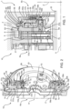
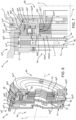
Figure 1 is a cross-section of a braking assembly of an agricultural vehicle according to a first embodiment of the present invention showing a clearance recovering device; -
Figure 2 is a cutaway perspective view of the braking assembly ofFigure 1 ; -
Figure 3 is a further cross-section of the braking assembly ofFigures 1 and 2 ; -
Figure 4 is a cross-section of a braking assembly of an agricultural vehicle according to a second embodiment of the present invention showing a clearance recovery device; -
Figures 4A, 4B, 4C and 4D are detailed views of the clearance recovery device ofFigure 4 in respective different operative conditions; -
Figures 5 is a cross-section of a braking assembly of an agricultural vehicle according to a third embodiment of the present invention; -
Figure 6 is a cutaway perspective view of the braking assembly ofFigure 5 ; -
Figures 7 is a cross-section of a braking assembly of an agricultural vehicle according to a fourth embodiment of the present invention; -
Figure 8 is a cutaway perspective view of the braking assembly ofFigure 7 ; and -
Figures 9 is a cross-section of a braking assembly of an agricultural vehicle according to a fifth embodiment of the present invention. - With reference to
Figure 1 ,numeral 1 indicates a work vehicle, which is only partially sketched, in particular an agricultural vehicle such as a tractor.Vehicle 1 comprises amain body 2 and a plurality of not-shown wheels, which are rotatable about respective rotational axes A so as to movemain body 2 with respect to the ground. -
Work vehicle 1 comprises two front wheels and two rear wheels according to a longitudinal advancement direction ofvehicle 1. In detail, the two rear wheels are mounted on arespective axle 20 ofwork vehicle 1, are rotatable about coincident rotational axes A and are spaced from each other along the rotational axes A. In further detail,vehicle 1 comprises twobraking assemblies 10, which are adapted to brake a respective rear wheel. - For the sake of simplicity, in the following of the present description reference will be made to a
single braking assembly 10 adapted to brake one of the two rear wheels, the description of abraking assembly 10 adapted to brake the other rear wheel being identical. - As illustrated in
Figure 1 ,braking assembly 10 comprises twobrake discs -
Brake discs Figures 1 and 2 ). In addition, preferably,brake discs -
Brake assembly 10 further comprises anintermediate disc 6, which is rotationally fixed (i.e., not rotatable with respect to main body 2), and which is interposed betweenbrake discs - Preferably,
braking assembly 10 also comprises at least one not-shown anti-rotational device ofintermediate disc 6, which is adapted to prevent the rotation ofintermediate disc 6 about rotational axis A relative tomain body 2. In detail, the anti-rotational device comprises a pin, which is fixed to bothintermediate disc 6 andmain body 2. Preferably,braking assembly 10 comprises three anti-rotational devices ofintermediate disc 6, which are spaced from one another by 120° circumferentially with respect to rotational axis A. -
Intermediate disc 6 defines afirst side 6a and asecond side 6b, which are opposite to each other, in particular with respect to a median plane ofintermediate disc 6. More specifically,intermediate disc 6 is arranged coaxially to rotational axis A and the rear wheel, which is braked by thebraking assembly 10, is arranged onsecond side 6b with respect tointermediate disc 6. Preferably,intermediate disc 6 is shaped like an annulus. In addition,brake disc 7 is arranged onfirst side 6a andbrake disc 8 is arranged onsecond side 6b. -
Brake discs respective faces intermediate disc 6 andrespective faces brake discs - In the embodiment shown,
brake disc 7 comprises a friction material at an external surface thereof, in detail atface 7b;brake disc 8 comprises a friction material at an external surface thereof, in detail atface 8b. - It is further possible to define a direction Z, which is orthogonal to rotational axis A. Direction Z is vertical to the ground on which the wheels rest during operation.
-
Brake discs intermediate disc 6 are slidable parallel to rotational axis A with respect tomain body 2.Braking assembly 10 further comprises areaction support 21, which is arranged opposite tointermediate disc 6 with respect tobrake disc 7. -
Reaction support 21 is fixed with respect tomain body 2. Accordingly,reaction support 21 is rotationally fixed and cannot slide parallel to rotational axis A. Preferably,reaction support 21 is shaped like as an annulus and is arranged coaxially to rotational axis A. -
Braking assembly 10 further comprises apiston 53, which is adapted to pressbrake disc 8,intermediate disc 6 andbrake disc 7 againstreaction support 21, in order to obtain a braking action of the rear wheel. - In detail,
piston 53 may be set to a first configuration, in which it pressesbrake disc 8 or to a second configuration, in which it does not pressbrake disc 8 and is spaced therefrom. -
Work vehicle 1 comprises ahydraulic system 90 for the actuation ofpiston 53, which will be described in detail below. Piston 53 may be actuated by a driver ofvehicle 1. In detail,piston 53 is actuated by a brake command oil pressure, which is generated with a master cylinder pump or a hydraulic valve or any other alternative hydraulic oil pressure source inside a vehicle cabin, for example by means of a pedal. - Piston 53 is opposite to
intermediate disc 6 with respect tobrake disc 8 parallel to rotational axis, is rotationally fixed and arranged coaxially to rotational axis A andaxle 20. - Piston 53 is slidable parallel to rotational axis A. In detail,
piston 53 is adapted toabut brake disc 8 on the side offace 8a and to slidebrake discs intermediate disc 6 towardsreaction support 21. In detail,piston 53 is a service brake piston. - In detail,
piston 53 comprises an annularshaped body 57 and aprotrusion 58 extending from annularshaped body 57 parallel to rotationalaxis A. Protrusion 58 extends from annularshaped body 57 on the side opposite tobrake disc 8 and preferably over the entire circumference of annularshaped body 57. - Annular
shaped body 57 comprises aface 57a adapted to directlycontact brake disc 8 and aface 57b, which is opposite to face 57a with respect to a median plane ofpiston 53 along rotational axis A. Preferably,faces - Annular shaped
body 57 further comprises a radiallyouter surface 57c and a radiallyinner surface 57d with respect to rotational axis A. In the embodiment shown, radiallyouter surface 57c and radiallyinner surface 57d are cylindrical and concentrical to rotational axis A. -
Protrusion 58 comprises a radiallyinner surface 58a and a radiallyouter surface 58b with respect to rotational axis A. In the embodiment shown, radiallyinner surface 58a and radiallyouter surface 58b are cylindrical and concentrical to rotational axis A. - More specifically, radially
inner surface 58a is interposed between radiallyouter surface 58b and radiallyinner surface 57d radially with respect to rotational axis A. In addition, radiallyouter surface 58b is radially closer to rotational axis A than radiallyouter surface 57c. - Furthermore,
piston 53 comprises threeholes 53a.Holes 53a are through holes and are arranged at annular shapedbody 57. In detail, holes 53a are cylindrical holes directed parallel to rotational axis A and are at least in part threaded. In the embodiment shown, holes 53a are spaced from one another by 120° circumferentially with respect to rotational axis A. In further detail, holes 53a are radially interposed between radiallyinner surface 58a and radiallyinner surface 57d. - Advantageously, braking
assembly 10 comprises afurther brake piston 54, which is adapted to at least indirectly cooperate withbrake disc 8 and aspring 55, which is adapted to elastically pre-loadpiston 54 to cooperate withbrake disc 8. -
Piston 54 is actuated independently ofpiston 53. In detail,work vehicle 1 comprises ahydraulic system 91 for the actuation ofpiston 54, which will be described in detail below.Hydraulic system 91 is adapted to counteract the spring force exerted onpiston 54 byspring 55 in order to releasebrake disc 8. Accordingly,piston 54,spring 55 andhydraulic system 91 define a SAHR brake ofwork vehicle 1. - The release of
piston 54 is commanded by the driver, by way of example inside the vehicle cabin with an operating means, such as a lever. - In detail,
piston 54 is opposed tobrake disc 8 with respect topiston 53 along rotational axis A. In addition,piston 54 is adapted to cooperate withbrake disc 8 throughbrake piston 53. In other words,piston 54 is adapted to exert its braking action onbrake disc 8 by means ofpiston 53 andpiston 54 is not adapted to directly contactbrake disc 8. -
Piston 54 comprises an annular shapedbody 59 and aprotrusion 60 extending from annular shapedbody 59 parallel to rotational axis A. In detail,protrusion 60 extends from annular shapedbody 59 towardspiston 53, preferably along the entire circumference of annular shapedbody 59. - Annular shaped
body 59 comprises aface 59a, which is oriented towardspiston 53 and aface 59b, which is opposite to face 59a with respect to a median plane ofpiston 54 along rotational axis A. Preferably, faces 59a and 59b are planar or substantially planar and directed orthogonally to rotational axis A. - Annular shaped
body 59 further comprises a radiallyinner surface 59d with respect to rotational axis A. In the embodiment shown, radiallyinner surface 59d is cylindrical and concentrical to rotational axis A. -
Protrusion 60 comprises a radiallyinner surface 60a and a radiallyouter surface 60b with respect to rotational axis A. In the embodiment shown, radiallyinner surface 60a and radiallyouter surface 60b are cylindrical and concentrical to rotational axis A. - In other words, a cross-section of
piston 54 in a plane passing through rotational axis A is U-shaped. - As shown in
Figures 1 and 2 ,protrusion 60 is adapted to contactpiston 53 atface 57b. Moreover, radiallyouter surface 60b is adapted to face radiallyinner surface 58a and/or to slidably contact radiallyinner surface 58a. -
Braking assembly 10 further comprises asupport element 56, which is fixed tomain body 2 and is adapted to slidablysupport brake piston 54 with respect tomain body 2. -
Support element 56 comprises an annular shapedbody 61 and aprotrusion 62 extending from annular shapedbody 61 parallel to rotational axis A. In detail,protrusion 62 extends from annular shapedbody 61 on the side opposite tobrake disc 8 and preferably over the entire circumference of annular shapedbody 61. - In detail, annular shaped
body 61 is spaced apart frompiston 53 along rotational axis A. In addition, annular shapedbody 61 is arranged radially inside (i.e., radially closer to rotational axis A) with respect to radiallyinner surface 60a with respect to rotational axis A;protrusion 62 is arranged radially inside with respect to radiallyinner surface 59d. -
Support element 56 further comprises threeholes 56a.Holes 56a are through holes and are each aligned to arespective hole 53a parallel to rotational axis A. In detail, holes 56a are cylindrical holes directed parallel to rotational axis A. In the embodiment shown, holes 56a are spaced from one another by 120° circumferentially with respect to rotational axis A. -
Spring 55 is arranged on the side ofbrake piston 54 opposite tobrake disc 8 along rotational axis A. In detail,spring 55 is adapted to exert its elastic force ontoface 59b. In the embodiment shown,spring 55 is a Belleville spring. -
Braking assembly 10 also comprise abody 63, which is in contact withmain body 2 and fixed thereto (Figure 1 ).Body 63 is arranged radially externally topiston 53 and comprises astretch 64, which is directed orthogonally to rotational axis A. In detail,spring 55 is in contact withstretch 64 on the side opposite topiston 54. - According to a not-shown embodiment,
body 63 is integrated withmain body 2. -
Braking assembly 10 further comprises threeclearance recovery devices 70, which are adapted to limit the stroke ofbrake piston 53 from the second configuration to the first configuration parallel to rotational axis A. In detail,clearance recovery devices 70 are adapted to limit the stroke ofbrake piston 53 specifically whenbrake discs 7 and/or 8 are worn. - In the following of the present description, only one
clearance recovery device 70 will be described, being allclearance recovery devices 70 identical to one another. -
Clearance recovery device 70 comprises: - a
pin 71, which is integral withpiston 53 and slidably engaged in ahole 56a; and - elastic means 72, which are adapted to cooperate with both
pin 71 andhole 56a. - In detail,
pin 71 is in part engaged in arespective hole 53a and in part engaged in thehole 56a aligned with therespective hole 53a. - In addition, elastic means 72 comprise an elastic bushing, which is arranged within
hole 56a. In further detail, each elastic bushing is arranged in the room radially interposed betweenpin 71 and the surface ofhole 56a and is in contact with the surface ofhole 56a. More specifically, the surface ofhole 56a exerts a frictional force on the coil spring. -
Clearance recovery device 70 further comprises anut 73, which is screwed ontopin 71 at the axial end ofpin 71 opposite topiston 53.Nut 73 is adapted to limit the axial movement ofelastic means 72. In detail,nut 73 prevents elastic means 72 from sliding out ofhole 56a in the direction oriented frombrake disc 7 tobrake disc 8. - In further detail, proceeding parallel to rotational axis A from the axial end of
pin 71 that is engaged intohole 53a towards the axial end ofpin 71 that is engaged intohole 56a,pin 71 comprises: - a first longitudinal stretch, which is threaded and screwed to the thread of
hole 53a; - a second longitudinal stretch, which is adapted to abut elastic means 72 in at least some operational conditions of
clearance recovery device 70; the extension of the cross-section of the second longitudinal stretch is greater than the extension of the cross-section of the first longitudinal stretch and the extension of the cross-section of elastic means 72 in a plane perpendicular to rotational axis A; and - a third longitudinal stretch, which is not threaded and which engages
hole 56a. - In detail, elastic means 72 are arranged about the third longitudinal stretch.
-
Pin 71 preferably comprises also a fourth longitudinal stretch, which is threaded and which protrudes outsidehole 56a on the side opposite topiston 53.Nut 73 is screwed to pin 71 at the fourth longitudinal stretch. - In detail, between the elastic bushing of
elastic means 72 and the inner surface ofhole 56a there is a friction coefficient that allows the elastic bushing to slide relative to hole 56a only when the axial force applied topiston 53 is higher than the friction force acting between the elastic bushing and the inner surface ofhole 56a. In addition,hydraulic system 90 is adapted to exert forces onpiston 53 that are greater whenpiston 53 is to be moved from the second configuration to the first configuration than whenpiston 53 is to be moved from the first configuration to the second configuration. - When the braking action is commanded,
piston 53 is moved toward the first configuration and the elastic bushing tends to slide relative to hole 56a towardbrake disc 8 and integrally withpin 71. - When the braking action is stopped again,
piston 53 is moved toward the second configuration and the elastic bushing tends to remain stationary with respect tohole 56a (i.e., it tends not to slide with respect tohole 56a). As a result, the second longitudinal stretch ofpin 71 abuts the elastic bushing and the movement ofpiston 53 away frombrake disc 8 is stopped. - This is especially advantageous when the surfaces of
brake discs piston 53 from the second configuration to the first configuration should become gradually larger to compensate for the wear ofbrake discs brake disc 8 at the end of each activation ofpiston 53, and since the travel ofpiston 53 away frombrake disc 8 is stopped by the elastic bushing,piston 53 in the second configuration does not return to the axial position it would have reached when the surfaces ofbrake discs brake disc 8. This ensures that the stroke ofpiston 53 between the second configuration and the first configuration remains the same or essentially the same over time even when the brake disc surfaces 7 and 8 are worn. - The fact that the elastic bushing slides with respect to
hole 56a whenpiston 53 moves towardbrake disc 8 and does not slide with respect tohole 56a whenpiston 53 moves away frombrake disc 8 is due to the forces with whichpiston 53 is moved with respect tobrake disc 8. In detail, whenpiston 53 moves towardbrake disc 8 the forces involved are greater than those acting onpiston 53 when it moves away frombrake disc 8. In more detail, whenpiston 53 moves towardbrake disc 8 the forces acting onpiston 53 are greater than the (maximum) frictional forces acting between the elastic bushing and the inner surfaces ofhole 56a. In contrast, whenpiston 53 moves away frombrake disc 8 the forces acting onpiston 53 are lower than the frictional forces acting between the elastic bushing and the inner surfaces ofhole 56a. - Preferably, braking
assembly 10 also comprises at least oneanti-rotational device 42 ofpiston 53, which is adapted to prevent the rotation ofpiston 53 about rotational axis A relative tomain body 2. In detail,anti-rotational device 42 comprises a pin, which is fixed to bothpiston 53 andsupport element 56. In further detail, the pin is in part engaged in a corresponding hole ofpiston 53 and in part engaged in a corresponding hole ofsupport element 56. - In the embodiment shown, braking
assembly 10 comprises threeanti-rotational devices 42, which are spaced from one another by 120° circumferentially with respect to rotational axis A. -
Figure 3 showshydraulic systems pistons - In detail,
piston 53 andbody 63 define acavity 92, which is adapted to receive the hydraulic fluid for the actuation ofpiston 53 andhydraulic system 90 comprises anopening 93 atcavity 92. - In further detail,
hydraulic system 90 comprises a plurality ofducts 94 for the hydraulic fluid and comprisingopening 93. In the embodiment shown,ducts 94 are at least partially integrated intomain body 2 andbody 63. - Furthermore,
piston 54 andsupport element 56 define acavity 95, which is adapted to receive the hydraulic fluid for the actuation ofpiston 54 andhydraulic system 91 comprises anopening 96 atcavity 95. - In further detail,
hydraulic system 91 comprises a plurality ofducts 97 for the hydraulic fluid and comprisingopening 96. In the embodiment shown,ducts 97 are at least partially integrated intomain body 2 andsupport element 56. - For the sake of conciseness,
hydraulic system 91 is arranged as inpatent application EP3760503 in the name of the same Applicant. - Furthermore, braking
assembly 10 comprises sealing means 98, which are adapted to sealcavity 92 and to prevent the hydraulic fluid released from opening 93 from escaping fromcavity 92. In detail, sealing means 98 are interposed betweenpiston 53 andbody 63. -
Braking assembly 10 also comprises sealing means 99, which are adapted to sealcavity 95 and to prevent the hydraulic fluid released from opening 96 from escaping fromcavity 95. In detail, sealing means 99 are interposed betweenpiston 54 andsupport element 56. -
Braking assembly 10 preferably comprises an oil sump - not shown - that is adapted to collect a lubricating fluid fallen by gravity after it has lubricatedintermediate disc 6 and/orbrake discs intermediate disc 6 andbrake discs - The operation of the
braking assembly 10 described as above is the following. - In use, elastic means 55 constantly exert the spring force on
piston 54, which is biased towardsdisc brake 8 andhydraulic system 91 counteracts the spring force by means of the hydraulic fluid intocavity 95. In detail, the hydraulic fluid flows throughducts 97, passes throughopening 96 and causespiston 54 to move away fromsupport element 56. In further detail,piston 54 slides with respect to supportelement 56 in a direction opposite to brake disc 8 (i.e., towards the right according to the arrangement shown inFigure 3 ) . - When the driver of
work vehicle 1 commands a braking action by means of the pedal,piston 53 is actuated byhydraulic system 90 and pushesbrake discs intermediate disc 6 againstreaction support 21. In detail, the hydraulic fluid flows throughducts 94, passes throughopening 93 and causespiston 53 to move towards brake disc 8 (i.e., towards the left according to the arrangement shown inFigure 3 ). - When the driver commands the SAHR brake to exert its braking action, the
hydraulic system 91 ceases to fully counteract the action ofelastic means 55, thus allowingpiston 54 to slide towardpiston 53.Piston 54 then pushes againstpiston 53, which in turn pushesbrake discs intermediate disc 6 againstreaction support 21. - Furthermore, since
brake discs brake discs - With reference to
Figures 4, 4A, 4B, 4C and 4D , 1' denotes a work vehicle comprising a braking assembly 10' according to a second embodiment of the present invention. Work vehicle 1' and braking assembly 10' are respectively similar to workvehicle 1 andbraking assembly 10 and will be described hereinafter only insofar as they differ from the latter; equal or equivalent parts ofwork vehicles 1; 1' andbraking assemblies 10; 10' and will be marked, where possible, by the same reference numerals. - Work vehicle 1' differs from
work vehicle 1 in that it comprises braking assembly 10' instead of brakingassembly 10. Braking assembly 10' differs from brakingassembly 10 in that it comprises clearance recovery devices 70' instead ofclearance recovery devices 70. - In the following of the present description, only one clearance recovery device 70' will be described, being all clearance recovery devices 70' identical to one another.
- Analogously to
clearance recovery devices 70, clearance recovery devices 70' is adapted to limit the stroke of brake piston 53' from the second configuration to the first configuration parallel to rotational axis A. - Clearance recovery device 70' comprises:
- a pin 71', which is integral with support element 56' and slidably engaged in a
hole 53a'; and - elastic means 72', which are adapted to cooperate with both pin 71' and
hole 53a'. - In detail, elastic means 72' comprise an elastic bushing, which is at least partially arranged within
hole 53a'. In further detail, each elastic bushing is arranged in the room radially interposed between pin 71' and the surface ofhole 53a' and is in contact with the surface ofhole 53a'. More specifically, the surface ofhole 53a' exerts a frictional force on the elastic bushing. - In further detail, proceeding parallel to rotational axis A from the axial end of pin 71' that is engaged into
hole 56a' towards the axial end of pin 71' that is engaged intohole 53a',pin 71 comprises: - a first longitudinal stretch, which is threaded and screwed to the thread of
hole 56a'; - a second longitudinal stretch, which is adapted to abut the surface of support element 56' facing piston 53' (in at least some operational conditions of clearance recovery device 70'); the extension of the cross-section of the second longitudinal stretch is greater than the extension of the cross-section of the first longitudinal stretch in a plane perpendicular to rotational axis A. The second longitudinal stretch engages at least in
part hole 53a'; and - a third longitudinal stretch, which is at least partially arranged within
hole 53a'; the extension of the cross-section of the third longitudinal stretch is greater than the extension of the cross-section of the second longitudinal stretch in a plane perpendicular to rotational axis A. - In particular, a portion of pin 71' and of the elastic bushing may extend in part outside of both
holes 56a' and 53a'. - In addition, elastic means 72' are adapted to cooperate with both support element 56' and pin 71'. In detail, the elastic bushing of elastic means 72' is adapted to abut the surface of support element 56' facing piston 53' and/or the third longitudinal stretch in at least some operational condition of clearance recovery device 70'.
- In detail, between the elastic bushing of elastic means 72' and the inner surface of
hole 53a' there is a friction coefficient that allows the elastic bushing to slide relative tohole 53a' only when the axial force applied to piston 53' is higher than the friction force acting between elastic means 72' and the inner surface ofhole 53a'. In addition, hydraulic system 90' is adapted to exert forces on piston 53' that are greater when piston 53' is to be moved from the second configuration to the first configuration than when piston 53' is to be moved from the first configuration to the second configuration. -
Figures 4A, 4B, 4C and 4D show respective different operational conditions of clearance recovery device 70'. - In detail,
Figure 4A shows clearance recovery device 70' in a first operational condition, in which brake piston 53' is released (i.e., disengaged; it does not exert a braking force on brake disc 8), the elastic bushing is axially distanced from the third longitudinal stretch and abuts support element 56'. In addition, brake piston 53' abuts support element 56'. In further detail, during the release of brake piston 53', brake piston 53' and the elastic bushing are moved away frombrake disc 8 substantially by the same amount parallel to longitudinal axis A. In other words, during the release of brake piston 53', there is no relative motion between brake piston 53' and the elastic bushing. -
Figure 4B shows clearance recovery device 70' in a second operational condition, in which brake piston 53' is moved from the second configuration towards the first configuration. During the movement of brake piston 53', the elastic bushing abuts the third longitudinal stretch and is distanced from support element 56' parallel to longitudinal axis A. In further detail, during the engagement of brake piston 53', brake piston 53' and the elastic bushing are moved towardsbrake disc 8 substantially by the same amount parallel to longitudinal axis A. -
Figure 4C shows clearance recovery device 70' in a third operational condition, in which brake piston 53' is in contact withbrake disc 8 and the surfaces ofbrake disc 7 and/or 8 have a higher level of wear than in the first or second operating condition. In detail, during the engagement of brake piston 53', brake piston 53' and the elastic bushing are moved towardsbrake disc 8 parallel to longitudinal axis A. However, in view of the higher level of wear ofbrake disc 7 and/or 8 and the corresponding lower thickness ofbrake disc 7 and/or 8 parallel to rotational axis A, the stroke of brake piston 53' would be greater than the stroke of brake piston 53' in the first or second operational condition. In further detail, during the movement of brake piston 53' towardbrake disc 8, the elastic bushing abuts third longitudinal stretch and brake piston 53' slides relative to the elastic bushing towardsbrake disc 8. -
Figure 4D shows clearance recovery device 70' in a fourth operational condition following the third operational condition, in which brake piston 53' is released (the surfaces ofbrake disc 7 and/or 8 have the same level of wear as in the third operational condition). During the movement of brake piston 53' from the first configuration toward the second configuration, brake piston 53' and the elastic bushing are moved away frombrake disc 8 parallel to longitudinal axis A. Since during the release of brake piston 53' the friction forces acting between elastic means 72' and the inner surface ofhole 53a' are greater than the forces exerted by hydraulic system 90' on piston 53', substantially no relative movement between brake piston 53' and the elastic bushing is possible. As a result, at the end of the release of brake piston 53', brake piston 53' is shifted towardbrake disc 8. Accordingly, clearance recovery device 70' allows to recover the clearance due to the wear ofbrake disc 7 and/or 8. - Preferably, in the first and second operational conditions,
brake disc 7 and/or 8 and clearance recovery device 70' are not worn or have minimal wear. For example,brake disc 7 and/or 8 and free space recovery device 70' are new and newly installed on work vehicle 1'. - The operation of braking assembly 10' is similar to the operation of
braking assembly 10 and will not be described in detail, as it would be clear to a person skilled in the art in view of the description of the operation ofbraking assembly 10 and ofFigures 4A, 4B, 4C and 4D . - With reference to
Figures 5 and 6 , 1'' denotes a work vehicle comprising a braking assembly 10'' according to a third embodiment of the present invention.Work vehicle 1" and braking assembly 10'' are respectively similar to workvehicle 1 andbraking assembly 10 and will be described hereinafter only insofar as they differ from the latter; equal or equivalent parts ofwork vehicles 1; 1" andbraking assemblies 10; 10" and will be marked, where possible, by the same reference numerals. -
Work vehicle 1" differs fromwork vehicle 1 in that it comprises braking assembly 10'' instead of brakingassembly 10. Braking assembly 10'' differs from brakingassembly 10 in that piston 53'' is arranged radially externally to piston 54'' with respect to rotational axis A and piston 54'' is adapted to cooperate withbrake disc 8 without the interposition of piston 53''. -
Braking assembly 10" also comprises anintermediate plate 80", which is adapted to directly (i.e., without the interposition of further elements)contact brake disc 8. Intermediate plate 80'' is interposed betweenbrake disc 8 and piston 53'' and/orpiston 54" along rotational axis A. - Piston 53'' is adapted to cooperate with
brake disc 8 throughintermediate plate 80" andpiston 54" is adapted to cooperate withbrake disc 8 throughintermediate plate 80". - Preferably,
piston 53" is adapted to directly contact intermediate plate 80''; nevertheless, one or more elements might be interposed betweenpiston 53" andintermediate plate 80". - As shown in
Figures 5 and 6 ,intermediate plate 80" comprises an annular body comprising aface 80a'' facingbrake disc 8 and aface 80b" facingpistons 53" and 54''. In detail, faces 80a' ' and 80b' ' are planar and orthogonal to rotational axis A. -
Intermediate plate 80" is rotationally fixed with respect to rotational axis A, but it is slidable parallel to rotational axis A. In detail, braking assembly 10'' comprises at least oneanti-rotational device 81" of intermediate plate 80'', which is adapted to prevent the rotation ofintermediate plate 80" about rotational axis A relative tomain body 2. In detail,anti-rotational device 81" comprises a pin, which is in part engaged in a corresponding hole of pistonintermediate plate 80" and in part engaged in a corresponding hole ofmain body 2. - Preferably, the pin of
anti-rotational device 81" is also adapted to holdintermediate disc 6 against rotation. In particular, an intermediate portion of the pin also passes throughintermediate disc 6. - Preferably, intermediate plate 80'' comprises a plurality of
holes 80c" ' - only one of which is shown inFigure 5 - which are adapted to be crossed by the lubricating fluid. In detail, holes 80c" are arranged radially from a radially innermost surface ofintermediate plate 80" towards a radially outermost surface ofintermediate plate 80". -
Piston 53" comprises an annular body defining an opening 82'', which is cylindrical and concentrical to rotational axisA. Support element 56" is radially arranged within opening 82" and the inner surfaces of opening 82" is adapted to slidablycontact support element 56". - Furthermore, preferably but not necessarily, the radially outermost surface of
support element 56" is aligned to the radially outermost surface of piston 54'' radially with respect to rotational axis A. In addition, piston 54'' is only in part arranged within opening 82''. -
Braking assembly 10" also comprises a plurality of pushing elements 83''- six in the embodiment shown - which are carried by piston 54'' and are adapted to directly contactintermediate plate 80". - Pushing elements 83'' extend from
piston 54" on the side ofpiston 54" facingintermediate plate 80" and are adapted to slide relative to support element 56'' integrally withpiston 54" . - In detail,
support element 56" comprises a plurality ofholes 84", which are each slidably engaged by a respective pushingelement 83". In further detail, holes 84" are through holes, are cylindrical in shape and directed parallel to rotational axis A. - In further detail, each pushing element 83'' comprises a
columnar body 83a'', which is parallel to rotational axis A, and a contactingelement 83b'', which is opposite to piston 54'' with respect tocolumnar body 83a''.Columnar body 53a'' is engaged within the respective hole 84''; contactingelement 83b" is arranged outside therespective hole 84" and is adapted to contactface 80b". - The operation of braking assembly 10'' is similar to the operation of
braking assembly 10 and will be described only insofar as it differs therefrom. - In detail, the operation of
braking assembly 10" differs from the operation ofbraking assembly 10 in thatpiston 53" interacts withbrake disc 8 by pushingintermediate plate 80 and thatpiston 54" interacts withbrake disc 8 by thrusting pushingelements 83" againstintermediate plate 80. In further detail, whenpiston 54" interacts withbrake disc 8, it is not necessary for piston 53'' to be in contact withintermediate plate 80. - With reference to
Figures 7 and 8 , 1III denotes a work vehicle comprising abraking assembly 10III according to a fourth embodiment of the present invention.Work vehicle 1III andbraking assembly 10III are respectively similar to workvehicle 1" andbraking assembly 10" and will be described hereinafter only insofar as they differ from the latter; equal or equivalent parts ofwork vehicles 1"; 1III andbraking assemblies 10"; 10III and will be marked, where possible, by the same reference numerals. -
Work vehicle 1III differs fromwork vehicle 1" in that it comprises brakingassembly 10III instead of brakingassembly 10".Braking assembly 10III differs from braking assembly 10'' in thatspring 55III is arranged radially internally relative topiston 53III andsupport element 56III with respect to rotational axis A. Preferably,spring 55III is arranged completely radially internally relative topiston 53III andsupport element 56III. - In detail,
piston 54III comprises aseat 85III on the side opposite tointermediate plate 80III, which is adapted to house at least inpart spring 55III.Seat 85III is defined completely radially internally relative topiston 53III andsupport element 56III. - Furthermore,
piston 54III is adapted to directly cooperate with and/or contactintermediate plate 80III. In detail,piston 54III is adapted to directly cooperate with and/or contactintermediate plate 80III without the interposition ofpiston 53III or pushingelements 83". In further detail, proceeding parallel to rotational axis A in the direction oriented frombrake disc 7 tobrake disc 8,piston 54III comprises: - a stretch 540III, which is directed orthogonally to rotational axis A and adapted to
abut face 80bIII ; - a
stretch 541III, which is directed parallel to rotational axis A and which definesseat 85III; and - a stretch 542III, which is directed orthogonally to rotational axis A and opposite to
piston 53III with respect to supportelement 56III. In detail, stretch 542III is spaced apart fromsupport element 56III parallel to rotational axis A. -
Support element 56III abutsmain body 2 on the side opposite tobrake disc 8. In addition, brakingassembly 10III comprises an axial stop device 86III, which is fixed tomain body 2 and is adapted to cooperate withsupport element 56III on the side ofbrake disc 8. In detail, axial stop device 86III is adapted to preventsupport element 56III from sliding parallel to rotational axis A towardsbrake disc 8. Preferably, axial stop device 86III is a snap ring.Cavity 92III, which is adapted to receive the hydraulic fluid for the actuation ofpiston 53III, is defined bypiston 53III andsupport element 56III. In detail,cavity 92III is also partly delimited by axial stop device 86III. -
Piston 53III comprises an annular shapedbody 57III and aprotrusion 58III extending from annular shapedbody 57III parallel to rotationalaxis A. Protrusion 58III extends from annular shapedbody 57III on the side opposite tobrake disc 8 and preferably over the entire circumference of annular shapedbody 57III. In addition,support element 56III comprises a seat 87III, which is engaged at least in part byprotrusion 58III. - In addition,
spring 55III is arranged radially internally relative tocavity 92III andcavity 95III with respect to rotational axis A. - The operation of
braking assembly 10III is similar to the operation of braking assembly 10'' and will be described only insofar as it differs therefrom. - In detail, the operation of
braking assembly 10III differs from the operation ofbraking assembly 10" in thatpiston 54III interacts withbrake disc 8 by directly cooperating withintermediate plate 80III. In addition,spring 55III exerts its elastic force ontopiston 54III radially internally with respect topiston 53III andsupport element 56III. - With reference to
Figure 9 ,1 IV denotes a work vehicle comprising abraking assembly 10IV according to a fifth embodiment of the present invention.Work vehicle 1 IV andbraking assembly 10IV are respectively similar to workvehicle 1" andbraking assembly 10" and will be described hereinafter only insofar as they differ from the latter; equal or equivalent parts of work vehicles 1' ' ; 1IV and braking assemblies 10''; 10IV and will be marked, where possible, by the same reference numerals. -
Work vehicle 1IV differs fromwork vehicle 1" in that it comprises brakingassembly 10IV instead of brakingassembly 10".Braking assembly 10IV differs from braking assembly 10'' in that it comprises aclearance recovery device 70IV instead ofclearance recovery devices 70 or 70'. - In the following of the present description, only one
clearance recovery device 70IV will be described, being allclearance recovery devices 70IV identical to one another. -
Clearance recovery device 70IV comprises: - a
pin 71IV, which is integral withintermediate plate 80IV and slidably engaged in ahole 56aIV ofsupport element 56IV; - elastic means 72IV, which are adapted to cooperate with both
pin 71IV andhole 56aIV. - Elastic means 72IV are adapted to draw
intermediate plate 80IV back towardssupport element 56IV at the end of the actuation of thepiston 53IV. - In detail, elastic means 72IV comprise an elastic bushing, which is partially arranged within
hole 56aIV. In further detail, each elastic bushing is arranged in the room radially interposed betweenpin 71IV and the surface ofhole 56aIV and is in contact with the surface ofhole 56aIV. More specifically, the surface ofhole 56aIV exerts a frictional force on the elastic bushing. - In further detail, between the elastic bushing of
elastic means 72IV and inner surface ofhole 56aIV there is a friction coefficient that allows them to slide reciprocally only when the axial force applied tointermediate plate 80IV is higher than the friction force acting between the elastic bushing and inner surface ofhole 56aIV. In addition,hydraulic system 90IV is adapted to exert forces on intermediate plate 80IV (through piston 53IV) that are greater whenintermediate plate 80IV is to be moved towardsbrake disc 8 than whenintermediate plate 80IV is to be moved away frombrake disc 8. - In further detail, proceeding parallel to rotational axis A from the axial end of
pin 71IV that is engaged intohole 56aIV towards the axial end ofpin 71IV that is engaged into ahole 80aIV ofintermediate plate 80IV,pin 71IV comprises: - a first longitudinal stretch, which is partially arranged into
hole 56aIV; - a second longitudinal stretch, which is adapted to abut the surface of
intermediate plate 80IV facing piston 53IV (in at least some operational conditions of clearance recovery device 70IV); the extension of the cross-section of the second longitudinal stretch is smaller than the extension of the cross-section of the first longitudinal stretch in a plane perpendicular to rotational axis A. The second longitudinal stretch engages inpart hole 56aIV; and - a third longitudinal stretch, which is arranged within
hole 80aIV; the extension of the cross-section of the third longitudinal stretch is smaller than the extension of the cross-section of the second longitudinal stretch in a plane perpendicular to rotational axis A. - In detail,
hole 80aIV is a through cylindrical hole directed parallel to rotational axis A and is at least in part threaded. The third longitudinal stretch is threaded and meshes with the thread ofhole 80aIV. - In particular, a portion of
pin 71IV and of the elastic bushing extends in part outside of bothholes - In addition, elastic means 72IV are adapted to cooperate with both
support element 56IV andpin 71IV. In detail, the elastic bushing is adapted to abutintermediate plate 80IV and/or the first longitudinal stretch (in at least some operational conditions of clearance recovery device 70IV). - Furthermore, piston 53IV - similarly to piston 53''-comprises an annular body arranged coaxially to rotational axis A. Differently from piston 53'',
piston 53IV further comprises a protrusion extending radially inwardly with respect to rotational axis A. In detail, the protrusion is arranged at the axial end ofpiston 53IV facingintermediate plate 80IV. - Preferably but not necessarily,
support element 56IV comprises a notch at the axialend facing piston 53IV. In detail, in a plane passing through rotational axis A, the notch has a shape corresponding to the shape of the protrusion ofpiston 53IV. - Furthermore,
intermediate plate 80IV differs fromintermediate plate 80" in that the thickness thereof parallel to rotational axis A is not constant. In detail, the thickness ofintermediate plate 80IV at the radially innermost end thereof is the minimum thickness ofintermediate plate 80IV parallel to rotational axis A. In further detail, the thickness ofintermediate plate 80IV atholes 80aIV or in proximity toholes 80aIV is equal to the minimum thickness ofintermediate plate 80IV parallel to rotational axis A. - For the sake of clarity,
piston 54IV is adapted to cooperate withintermediate plate 80IV through pushing elements analogous to pushingelements 83". - The operation of
braking assembly 10IV is similar to the operation of braking assembly 10'' and will not be described in detail, as it would be clear to a person skilled in the art in view of the description of the operation ofbraking assembly 10". - In view of the foregoing, the advantages of
braking assembly 10; 10'; 10"; 10III; 10IV andwork vehicle 1; 1'; 1"; 1III; 1IV according to the invention are apparent. - In particular, since braking
assembly 10; 10'; 10"; 10III; 10IV comprises bothservice brake piston 53; 53'; 53"; 53III; 53IV andSAHR brake piston 54; 54'; 54"; 54III; 54IV and that bothpistons 53; 53'; 53"; 53III; 53IV, 54; 54'; 54"; 54III; 54IV are adapted to cooperate withbrake disc 8, the volume occupied by components used for vehicle braking is significantly reduced. Such a solution is significantly more compact than the known solutions discussed in the introductory part of the present description and provides greater design freedom for the vehicle. In detail, the space gained from the rearrangement of the SAHR brake and service brake can be advantageously used to mount additional components on board. - Moreover, since the
braking assembly 10; 10'; 10"; 10III; 10IV comprisesclearance recovery device 70; 70', 70IV, the clearance inevitably caused by wear can be advantageously and automatically recovered and repeatability of use ofbraking assembly 10; 10'; 10"; 10III; 10IV is ensured. In detail, sinceclearance recovery device 70; 70'; 70IV is arranged atsupport element 56; 56'; 56"; 56III; 56IV, in the event that theclearance recovery device 70; 70'; 70IV surfaces are worn or damaged, theclearance recovery device 70; 70'; 70IV can be restored easily by replacingsupport element 56; 56'; 56"; 56III; 56IV, without requiring replacement or rework of complex parts ofbraking assembly 10; 10'; 10"; 10III; 10IV such asmain body 2. - The embodiment wherein
piston 53; 53' directlycontacts brake disc 8 andpiston 54; 54' cooperates withbrake disc 8 throughpiston 53; 53' is particularly compact and requires minimum modifications ofpiston 53; 53' of existing disc brakes. - The embodiment wherein
piston 53"; 53III; 53IV is arranged radially externally topiston 54"; 54III; 54IV andpiston 54"; 54III; 54IV is adapted to cooperate withbrake disc 8 without the interposition of piston 53''; 53III; 53IV allows piston 54''; 54III; 54IV to be independent of piston 53''; 53III; 53IV. Moreover, the arrangement of piston 54''; 54III; 54IV is characterized by an advantageously large area over which the hydraulic oil can act to actuatepiston 54"; 54III; 54IV. - Since
spring 55III is arranged radially internally relative topiston 53III andsupport element 56III with respect to rotational axis A,spring 55III is spaced away fromhydraulic systems - It is clear that modifications can be made to the described
braking assembly 10; 10'; 10''; 10III; 10IV andwork vehicle 1; 1'; 1"; 1III; 1IV which do not extend beyond the scope of protection defined by the claims. - In particular,
work vehicle 1; 1'; 1"; 1III; 1IV might comprise only onebraking assembly 10; 10'; 10''; 10III; 10IV. -
Work vehicle 1; 1'; 1"; 1III; 1IV might comprise one ormore braking assemblies 10; 10'; 10''; 10III; 10IV adapted to brake one or both front wheels. -
Braking assembly 10; 10'; 10"; 10III; 10IV might comprise only onebrake disc brake discs -
Piston 53; 53'; 53"; 53III; 53IV and/orpiston 54; 54'; 54"; 54III; 54IV may be adapted to cooperate withbrake disc 7. -
Braking assembly 10 might comprise only oneclearance recovery devices 70, twoclearance recovery devices 70 or more than threeclearance recovery devices 70. Braking assembly 10'; 10"; 10III might comprise only one clearance recovery devices 70', two clearance recovery devices 70' or more than three clearance recovery devices 70'.Braking assembly 10IV might comprise only oneclearance recovery devices 70IV, twoclearance recovery devices 70IV or more than threeclearance recovery devices 70IV.Braking assembly 10; 10'; 10''; 10III; 10IV might comprise one or moreclearance recovery devices 70 and/or one or more than one clearance recovery devices 70' and/or one or more than oneclearance recovery devices 70IV. -
Braking assembly 10; 10'; 10''; 10III; 10IV might comprise only oneanti-rotational device 42, twoanti-rotational devices 42 or more than threeanti-rotational devices 42. -
Disc 6 might comprise a friction material at an external surface thereof anddiscs intermediate disc 6 might comprise the friction material both onfirst side 6a andsecond side 6b. -
Piston 53; 53' might comprise a number ofholes 53a; 53a' other than three. In detail,piston 53; 53' might comprise less than threeholes 53a; 53a' (i.e., one or two) or more than threeholes 53a; 53a'.Holes 53a; 53a' might be variously arranged. In addition,holes 53a; 53a' might be threaded or not. -
Braking assembly 10 may also comprise a plurality of pushing elements, by way of example six in number, which are carried bypiston 54 and are adapted to directly contactbrake disc 8. These pushing elements extend frompiston 54 on the side ofpiston 54 facingpiston 53 and are adapted to slide relative to supportelement 56 integrally withpiston 54. According to this not-shown embodiment,piston 53 comprises a plurality of first through holes andsupport element 56 comprises a plurality of second through holes, which are each aligned to a respective first through hole. Each pushing element slidably engages at the same time a respective first through hole and a respective second through hole. In detail, the first through holes and the second through holes are directed parallel to rotational axis A.
By way of example, each pushing elements comprises a columnar body, which is parallel to rotational axis A, and a contacting element, which is opposite topiston 54 with respect to the columnar body. The columnar body is engaged with the respective first and second through hole; the contacting element is arranged outside the respective first and second through holes and is adapted to contactbrake disc 8. Moreover, brakingassembly 10 might comprise an intermediate plate adapted to directly contactbrake disc 8 and interposed betweenbrake disc 8 andpiston 53 and/orpiston 54 along rotational axis A. According to this not-shown embodiment,piston 53 is adapted to cooperate withbrake disc 8 through the intermediate plate andpiston 54 is adapted to cooperate withbrake disc 8 through the pushing elements described above and the intermediate plate. Elastic means 72 might comprise a coil spring instead of or in addition to the elastic bushing.
Claims (16)
- Braking assembly (10; 10'; 10"; 10III; 10IV) for a work vehicle (1; 1'; 1"; 1III; 1IV) comprising:- a first brake disc (8, 7), which is adapted to rotate, in use, integrally with at least one wheel of said work vehicle (1; 1'; 1"; 1III; 1IV) about a rotational axis (A);- a first brake piston (53; 53'; 53"; 53III; 53IV), which is settable, in use, to a first configuration, in which it at least indirectly cooperates with said first brake disc (8, 7) or to a second configuration, in which it does not cooperate with said first brake disc (8, 7);wherein said braking assembly (10; 10'; 10"; 10III; 10IV) further comprises:- a second brake piston (54; 54'; 54"; 54III; 54IV), which is adapted to at least indirectly cooperate with said first brake disc (8, 7);- first elastic means (55; 55III), which are adapted to elastically urge, in use, said second brake piston (54; 54'; 54"; 54III; 54IV) to cooperate with said first brake disc (8, 7);- a support element (56; 56'; 56‴; 56III; 56IV), which is fixed to a main body (2) of said work vehicle (1; 1'; 1"; 1III; 1IV) and which is adapted to slidably support said second brake piston (54; 54"; 54‴; 54III; 54IV); and- at least one clearance recovery device (70; 70'; 70IV), which is supported by said support element (56; 56'; 56"; 56III; 56IV) and adapted to limit the stroke of said first brake piston (53; 53'; 53''; 53III; 53IV) from said second configuration to said first configuration.
- Braking assembly according to claim 1, wherein said clearance recovery device (70; 70') comprises:- an element (71; 71'), which is connected to one of said support element (56; 56'; 56"; 56III) and said first brake piston (53; 53'; 53"; 53III) and slidable with respect to the other one between said support element (56; 56'; 56"; 56III) and said first brake piston (53; 53'; 53"; 56III); and- second elastic means (72; 72'), which are adapted to cooperate with said element (71; 71') and said other one between said support element (56; 56'; 56"; 56III) and said first brake piston (53; 53'; 53"; 56III) with respect to whom said element (71; 71') is adapted to slide, in use.
- Braking assembly according to claim 2, wherein said support element (56) comprises at least one first hole (56a);said element (71) being integral with said first brake piston (53) and slidably engaged in said first hole (56a);said second elastic means (72) being arranged within said first hole (56a) radially between said element (71) and the surface of said first hole (56a); said second elastic means (72) being in contact with said surface of said first hole (56a) and being adapted to abut said element (71) in at least some operational condition of said clearance recovery device (70) .
- Braking assembly according to claim 3, wherein said first brake piston (53) comprises at least one second hole (53a), which is threaded and aligned to a respective first hole (56a); said element (71) being screwed to said second hole (53a).
- Braking assembly according to claim 3 or 4, wherein said clearance recovery device (70) further comprises an axial constraining device (73), which is mounted onto said element (71) at an axial end of said element (71) opposite to said first brake piston (53);
said axial constraining device (73) being adapted to limit the movement of said second elastic means (72) parallel to said rotational axis (A). - Braking assembly according to claim 2, wherein said first brake piston (53') comprises at least one first hole (53a');said element (71') being integral with said support element (56') and slidably engaged in a respective said first hole (53a');said second elastic means (72') being arranged in part within said first hole (53a') radially between said element (71') and the surface of said first hole (53a'); said second elastic means (72') being in contact with said surface of said first hole (53a') and being adapted to abut said element (71') in at least some operational condition of said clearance recovery device (70').
- Braking assembly according to claim 6, wherein said support element (56') comprises at least one second hole (56a'), which is threaded and aligned to a respective first hole (53a'); said element (71') being screwed to said second hole (56a').
- Braking assembly according to claim 1, further comprising an intermediate plate (80IV), which is slidable relative to said main body (2) and adapted to directly contact, in use, said first brake disc (8, 7);said intermediate plate (80IV) being interposed between said first brake disc (8, 7) and said first brake piston (53IV) and/or said second brake piston (54IV) along said rotational axis (A);said first brake piston (53IV) being adapted to cooperate with said first brake disc (8, 7) through said intermediate plate (80IV);said second brake piston (54IV) being adapted to cooperate with said first brake disc (8, 7) through said intermediate plate (80IV);wherein said clearance recovery device (70IV) comprises:- an element (71IV), which is connected to said intermediate plate (80IV) and slidable with respect to said support element (56IV); and- second elastic means (72IV), which are adapted to cooperate with said element (71IV) and said support element (56IV).
- Braking assembly according to claim 8, wherein said support element (56IV) comprises at least one first hole (56aIV);said element (71IV) being integral with said intermediate plate (80IV) and slidably engaged in said first hole (56aIV);said second elastic means (72IV) being arranged within said first hole (56aIV) radially between said element (71IV) and the surface of said first hole (56aIV); said second elastic means (72IV) being in contact with said surface of said first hole (56aIV) and being adapted to abut said element (71IV) in at least some operational condition of said clearance recovery device (70IV).
- Braking assembly according to claim 9, wherein said intermediate plate (80IV) comprises at least one second hole (80aIV), which is threaded and aligned to a respective first hole (56aIV); said element (71IV) being screwed to said second hole (80aIV).
- Braking assembly according to any one of the foregoing claims, further comprising:- a second brake disc (7, 8), which is adapted to rotate, in use, integrally with said wheel of said work vehicle (1; 1'; 1"; 1III; 1IV) about said rotational axis (A); said second brake disc (7, 8) being spaced from said first brake disc (8, 7) parallel to said rotational axis (A);- an intermediate disc (6), which is rotationally fixed relative to a main body (2) of said work vehicle (1; 1'; 1"; 1III; 1IV) and which is interposed between said first brake disc (8, 7) and said second brake disc (7, 8) parallel to said rotational axis (A).
- Braking assembly according to any one of claims 1 to 7, wherein said first brake piston (53; 53') is adapted to directly contact, in use, said first brake disc (8, 7);said second brake piston (54; 54') being opposed to said first brake disc (8, 7) with respect to said first brake piston (53; 53') along said rotational axis (A);said second brake piston (54; 54') being adapted to cooperate, in use, with said first brake disc (8, 7) through said first brake piston (53; 53').
- Braking assembly according to any one of claims 1 to 11, wherein said first brake piston (53"; 53III; 53IV) is arranged at least in part radially externally to said second brake piston (54"; 54III; 54IV) with respect to said rotational axis (A) and said second brake piston (54''; 54III; 54IV) is adapted to cooperate with said first brake disc (8, 7) without the interposition of said first brake piston (53''; 53III; 53IV).
- A work vehicle (1; 1'; 1"; 1III; 1IV) comprising:- a main body (2);- a plurality of wheels, which are adapted to move, in use, said main body (2) with respect to the ground; and- at least one braking assembly (10; 10'; 10"; 10III; 10IV) according to any one of the foregoing claims, which is adapted to brake, in use, one or more of said plurality of wheels.
- Work vehicle according to claim 14 comprising:- a first hydraulic system (90; 90'; 90''; 90III, 90IV), which is adapted to actuate said first brake piston (53; 53'; 53"; 53III; 53IV); and- a second hydraulic system (91), which is adapted to counteract, in use, the elastic force exerted by said first elastic means (55; 55III) on said second brake piston (54; 54'; 54"; 54III; 54IV).
- Working vehicle according to claim 15, wherein said first hydraulic system (90; 90'; 90"; 90III, 90IV), is adapted to exert, in use, on said first brake piston (53; 53'; 53"; 53III; 53IV):- a first force to move, in use, said first brake piston (53; 53'; 53"; 53III; 53IV) from said second configuration to said first configuration;- a second force to move, in use, said first brake piston (53; 53'; 53"; 53III; 53IV) from said first configuration to said second configuration;said first force being greater in magnitude than said second force;said first force being greater in magnitude than the maximum friction force acting, in use, between said second elastic means (72; 72'; 72IV) and said first hole (56a; 53a'; 56aIV) with whom they cooperate, in use;said second force being lower in magnitude than the maximum friction force acting, in use, between said second elastic means (72; 72'; 72IV) and said first hole (56a; 53a'; 56aIV) with whom they cooperate, in use.
Applications Claiming Priority (1)
| Application Number | Priority Date | Filing Date | Title |
|---|---|---|---|
| IT102023000022752A IT202300022752A1 (en) | 2023-10-30 | 2023-10-30 | BRAKING ASSEMBLY FOR A WORK VEHICLE |
Publications (1)
| Publication Number | Publication Date |
|---|---|
| EP4556739A1 true EP4556739A1 (en) | 2025-05-21 |
Family
ID=89573259
Family Applications (1)
| Application Number | Title | Priority Date | Filing Date |
|---|---|---|---|
| EP24209231.0A Withdrawn EP4556739A1 (en) | 2023-10-30 | 2024-10-28 | Braking assembly for a work vehicle |
Country Status (2)
| Country | Link |
|---|---|
| EP (1) | EP4556739A1 (en) |
| IT (1) | IT202300022752A1 (en) |
Citations (6)
| Publication number | Priority date | Publication date | Assignee | Title |
|---|---|---|---|---|
| EP0044007A1 (en) * | 1980-07-10 | 1982-01-20 | ALFRED TEVES GmbH | Actuating device for disk brakes |
| DE3121473A1 (en) * | 1981-05-29 | 1982-12-16 | Alfred Teves Gmbh, 6000 Frankfurt | Disc brake with brake disc rings attached alternately to the wheel and the brake anchor plate in a manner which prevents rotation |
| US5186284A (en) * | 1991-05-31 | 1993-02-16 | Case Corporation | Fail safe self-adjusting disc brake |
| US5427211A (en) * | 1994-01-10 | 1995-06-27 | Deere & Company | Piston stop pin for a hydraulic brake |
| EP1234993A1 (en) * | 2001-02-23 | 2002-08-28 | Dana Italia S.p.A | Wheel hub with integrated planetary gear and multiple disc brake |
| EP3760503A1 (en) | 2019-07-05 | 2021-01-06 | CNH Industrial Italia S.p.A. | Improved hydraulic brake arrangement for an off-road vehicle |
-
2023
- 2023-10-30 IT IT102023000022752A patent/IT202300022752A1/en unknown
-
2024
- 2024-10-28 EP EP24209231.0A patent/EP4556739A1/en not_active Withdrawn
Patent Citations (6)
| Publication number | Priority date | Publication date | Assignee | Title |
|---|---|---|---|---|
| EP0044007A1 (en) * | 1980-07-10 | 1982-01-20 | ALFRED TEVES GmbH | Actuating device for disk brakes |
| DE3121473A1 (en) * | 1981-05-29 | 1982-12-16 | Alfred Teves Gmbh, 6000 Frankfurt | Disc brake with brake disc rings attached alternately to the wheel and the brake anchor plate in a manner which prevents rotation |
| US5186284A (en) * | 1991-05-31 | 1993-02-16 | Case Corporation | Fail safe self-adjusting disc brake |
| US5427211A (en) * | 1994-01-10 | 1995-06-27 | Deere & Company | Piston stop pin for a hydraulic brake |
| EP1234993A1 (en) * | 2001-02-23 | 2002-08-28 | Dana Italia S.p.A | Wheel hub with integrated planetary gear and multiple disc brake |
| EP3760503A1 (en) | 2019-07-05 | 2021-01-06 | CNH Industrial Italia S.p.A. | Improved hydraulic brake arrangement for an off-road vehicle |
Also Published As
| Publication number | Publication date |
|---|---|
| IT202300022752A1 (en) | 2025-04-30 |
Similar Documents
| Publication | Publication Date | Title |
|---|---|---|
| US9599176B2 (en) | Disc brake having a restoring device and a brake pad | |
| US6378665B1 (en) | Pad retraction spring for disc brake assembly | |
| EP2125480B1 (en) | A rail vehicle brake slack adjuster | |
| US20140231189A1 (en) | Electric caliper brake | |
| CN115451044A (en) | Brake system for vehicle | |
| US3633715A (en) | Disc brake with spring brake and pressure-compensating self-adjuster | |
| US6719105B1 (en) | Pad retraction spring for disc brake assembly | |
| US5253737A (en) | Auxiliary brake force multiplying spring in a multidisc service and auxiliary brake system | |
| EP2174036B1 (en) | Brake caliper parking device | |
| US8851241B2 (en) | Hydraulic disc brake having a parking brake mechanism | |
| KR20070065880A (en) | Friction element and disc brake | |
| US3651896A (en) | Hydraulic disk brake with mechanical actuator | |
| CN117501029A (en) | Disc brake combined with electromechanical parking brake | |
| CN110199137A (en) | Disk brake | |
| EP2404799A2 (en) | Adhesive attachment of the disc brake push rod plate to the diaphragm | |
| EP4549770A1 (en) | Braking assembly for a work vehicle | |
| US5613577A (en) | Automotive disc brake with improved caliper assembly | |
| EP1236923A2 (en) | Automatic wear adjustment for disc brake pad | |
| US4550811A (en) | Manually releasable parking brake device | |
| US3726367A (en) | Combined service and parking brake | |
| US3322241A (en) | Brake system | |
| US12560210B2 (en) | Air disc brake system with caliper retraction and methods for the use and assembly thereof | |
| US12352325B2 (en) | Drum brake assembly | |
| JP2017172731A (en) | Braking device | |
| USH748H (en) | Air brake with collet locked push rod and excessive force reducer |
Legal Events
| Date | Code | Title | Description |
|---|---|---|---|
| PUAI | Public reference made under article 153(3) epc to a published international application that has entered the european phase |
Free format text: ORIGINAL CODE: 0009012 |
|
| STAA | Information on the status of an ep patent application or granted ep patent |
Free format text: STATUS: THE APPLICATION HAS BEEN PUBLISHED |
|
| AK | Designated contracting states |
Kind code of ref document: A1 Designated state(s): AL AT BE BG CH CY CZ DE DK EE ES FI FR GB GR HR HU IE IS IT LI LT LU LV MC ME MK MT NL NO PL PT RO RS SE SI SK SM TR |
|
| STAA | Information on the status of an ep patent application or granted ep patent |
Free format text: STATUS: REQUEST FOR EXAMINATION WAS MADE |
|
| 17P | Request for examination filed |
Effective date: 20251121 |
|
| STAA | Information on the status of an ep patent application or granted ep patent |
Free format text: STATUS: THE APPLICATION IS DEEMED TO BE WITHDRAWN |
|
| 18D | Application deemed to be withdrawn |
Effective date: 20251122 |