EP4556731A1 - Magnetlagervorrichtung und zentrifugalpumpe - Google Patents
Magnetlagervorrichtung und zentrifugalpumpe Download PDFInfo
- Publication number
- EP4556731A1 EP4556731A1 EP24210076.6A EP24210076A EP4556731A1 EP 4556731 A1 EP4556731 A1 EP 4556731A1 EP 24210076 A EP24210076 A EP 24210076A EP 4556731 A1 EP4556731 A1 EP 4556731A1
- Authority
- EP
- European Patent Office
- Prior art keywords
- rotor
- magnetic bearing
- bearing device
- magnetic field
- stator
- Prior art date
- Legal status (The legal status is an assumption and is not a legal conclusion. Google has not performed a legal analysis and makes no representation as to the accuracy of the status listed.)
- Granted
Links
Images


Classifications
-
- H—ELECTRICITY
- H02—GENERATION; CONVERSION OR DISTRIBUTION OF ELECTRIC POWER
- H02K—DYNAMO-ELECTRIC MACHINES
- H02K7/00—Arrangements for handling mechanical energy structurally associated with dynamo-electric machines, e.g. structural association with mechanical driving motors or auxiliary dynamo-electric machines
- H02K7/08—Structural association with bearings
- H02K7/09—Structural association with bearings with magnetic bearings
-
- F—MECHANICAL ENGINEERING; LIGHTING; HEATING; WEAPONS; BLASTING
- F16—ENGINEERING ELEMENTS AND UNITS; GENERAL MEASURES FOR PRODUCING AND MAINTAINING EFFECTIVE FUNCTIONING OF MACHINES OR INSTALLATIONS; THERMAL INSULATION IN GENERAL
- F16C—SHAFTS; FLEXIBLE SHAFTS; ELEMENTS OR CRANKSHAFT MECHANISMS; ROTARY BODIES OTHER THAN GEARING ELEMENTS; BEARINGS
- F16C32/00—Bearings not otherwise provided for
- F16C32/04—Bearings not otherwise provided for using magnetic or electric supporting means
- F16C32/0406—Magnetic bearings
- F16C32/044—Active magnetic bearings
- F16C32/0444—Details of devices to control the actuation of the electromagnets
- F16C32/0446—Determination of the actual position of the moving member, e.g. details of sensors
-
- F—MECHANICAL ENGINEERING; LIGHTING; HEATING; WEAPONS; BLASTING
- F04—POSITIVE - DISPLACEMENT MACHINES FOR LIQUIDS; PUMPS FOR LIQUIDS OR ELASTIC FLUIDS
- F04D—NON-POSITIVE-DISPLACEMENT PUMPS
- F04D13/00—Pumping installations or systems
- F04D13/02—Units comprising pumps and their driving means
- F04D13/06—Units comprising pumps and their driving means the pump being electrically driven
- F04D13/0686—Mechanical details of the pump control unit
-
- F—MECHANICAL ENGINEERING; LIGHTING; HEATING; WEAPONS; BLASTING
- F04—POSITIVE - DISPLACEMENT MACHINES FOR LIQUIDS; PUMPS FOR LIQUIDS OR ELASTIC FLUIDS
- F04D—NON-POSITIVE-DISPLACEMENT PUMPS
- F04D13/00—Pumping installations or systems
- F04D13/02—Units comprising pumps and their driving means
- F04D13/06—Units comprising pumps and their driving means the pump being electrically driven
- F04D13/0693—Details or arrangements of the wiring
-
- F—MECHANICAL ENGINEERING; LIGHTING; HEATING; WEAPONS; BLASTING
- F04—POSITIVE - DISPLACEMENT MACHINES FOR LIQUIDS; PUMPS FOR LIQUIDS OR ELASTIC FLUIDS
- F04D—NON-POSITIVE-DISPLACEMENT PUMPS
- F04D27/00—Control, e.g. regulation, of pumps, pumping installations or pumping systems specially adapted for elastic fluids
- F04D27/001—Testing thereof; Determination or simulation of flow characteristics; Stall or surge detection, e.g. condition monitoring
-
- F—MECHANICAL ENGINEERING; LIGHTING; HEATING; WEAPONS; BLASTING
- F04—POSITIVE - DISPLACEMENT MACHINES FOR LIQUIDS; PUMPS FOR LIQUIDS OR ELASTIC FLUIDS
- F04D—NON-POSITIVE-DISPLACEMENT PUMPS
- F04D29/00—Details, component parts, or accessories
- F04D29/04—Shafts or bearings, or assemblies thereof
- F04D29/046—Bearings
- F04D29/048—Bearings magnetic; electromagnetic
-
- F—MECHANICAL ENGINEERING; LIGHTING; HEATING; WEAPONS; BLASTING
- F16—ENGINEERING ELEMENTS AND UNITS; GENERAL MEASURES FOR PRODUCING AND MAINTAINING EFFECTIVE FUNCTIONING OF MACHINES OR INSTALLATIONS; THERMAL INSULATION IN GENERAL
- F16C—SHAFTS; FLEXIBLE SHAFTS; ELEMENTS OR CRANKSHAFT MECHANISMS; ROTARY BODIES OTHER THAN GEARING ELEMENTS; BEARINGS
- F16C32/00—Bearings not otherwise provided for
- F16C32/04—Bearings not otherwise provided for using magnetic or electric supporting means
- F16C32/0406—Magnetic bearings
- F16C32/044—Active magnetic bearings
- F16C32/0459—Details of the magnetic circuit
- F16C32/0461—Details of the magnetic circuit of stationary parts of the magnetic circuit
-
- F—MECHANICAL ENGINEERING; LIGHTING; HEATING; WEAPONS; BLASTING
- F16—ENGINEERING ELEMENTS AND UNITS; GENERAL MEASURES FOR PRODUCING AND MAINTAINING EFFECTIVE FUNCTIONING OF MACHINES OR INSTALLATIONS; THERMAL INSULATION IN GENERAL
- F16C—SHAFTS; FLEXIBLE SHAFTS; ELEMENTS OR CRANKSHAFT MECHANISMS; ROTARY BODIES OTHER THAN GEARING ELEMENTS; BEARINGS
- F16C32/00—Bearings not otherwise provided for
- F16C32/04—Bearings not otherwise provided for using magnetic or electric supporting means
- F16C32/0406—Magnetic bearings
- F16C32/044—Active magnetic bearings
- F16C32/047—Details of housings; Mounting of active magnetic bearings
-
- F—MECHANICAL ENGINEERING; LIGHTING; HEATING; WEAPONS; BLASTING
- F16—ENGINEERING ELEMENTS AND UNITS; GENERAL MEASURES FOR PRODUCING AND MAINTAINING EFFECTIVE FUNCTIONING OF MACHINES OR INSTALLATIONS; THERMAL INSULATION IN GENERAL
- F16C—SHAFTS; FLEXIBLE SHAFTS; ELEMENTS OR CRANKSHAFT MECHANISMS; ROTARY BODIES OTHER THAN GEARING ELEMENTS; BEARINGS
- F16C32/00—Bearings not otherwise provided for
- F16C32/04—Bearings not otherwise provided for using magnetic or electric supporting means
- F16C32/0406—Magnetic bearings
- F16C32/044—Active magnetic bearings
- F16C32/0474—Active magnetic bearings for rotary movement
- F16C32/0485—Active magnetic bearings for rotary movement with active support of three degrees of freedom
-
- F—MECHANICAL ENGINEERING; LIGHTING; HEATING; WEAPONS; BLASTING
- F05—INDEXING SCHEMES RELATING TO ENGINES OR PUMPS IN VARIOUS SUBCLASSES OF CLASSES F01-F04
- F05D—INDEXING SCHEME FOR ASPECTS RELATING TO NON-POSITIVE-DISPLACEMENT MACHINES OR ENGINES, GAS-TURBINES OR JET-PROPULSION PLANTS
- F05D2240/00—Components
- F05D2240/50—Bearings
- F05D2240/51—Magnetic
-
- F—MECHANICAL ENGINEERING; LIGHTING; HEATING; WEAPONS; BLASTING
- F05—INDEXING SCHEMES RELATING TO ENGINES OR PUMPS IN VARIOUS SUBCLASSES OF CLASSES F01-F04
- F05D—INDEXING SCHEME FOR ASPECTS RELATING TO NON-POSITIVE-DISPLACEMENT MACHINES OR ENGINES, GAS-TURBINES OR JET-PROPULSION PLANTS
- F05D2270/00—Control
- F05D2270/80—Devices generating input signals, e.g. transducers, sensors, cameras or strain gauges
-
- F—MECHANICAL ENGINEERING; LIGHTING; HEATING; WEAPONS; BLASTING
- F16—ENGINEERING ELEMENTS AND UNITS; GENERAL MEASURES FOR PRODUCING AND MAINTAINING EFFECTIVE FUNCTIONING OF MACHINES OR INSTALLATIONS; THERMAL INSULATION IN GENERAL
- F16C—SHAFTS; FLEXIBLE SHAFTS; ELEMENTS OR CRANKSHAFT MECHANISMS; ROTARY BODIES OTHER THAN GEARING ELEMENTS; BEARINGS
- F16C2360/00—Engines or pumps
- F16C2360/44—Centrifugal pumps
Definitions
- the invention relates to a magnetic bearing device according to the preamble of the independent patent claim and a centrifugal pump with such a magnetic bearing device.
- Magnetic bearing devices for contactless magnetic bearings of a rotor have the advantage that they do not require mechanical bearings for the rotor.
- the rotor is supported or stabilized by magnetic forces generated by a stator of the magnetic bearing device. Due to the absence of mechanical bearings, such magnetic bearing devices are particularly suitable for pumping, mixing, centrifuging, or stirring devices that convey very sensitive substances, such as blood pumps, or that have very high purity requirements, for example in the pharmaceutical or biotechnology industries, or that convey abrasive or aggressive substances that would quickly destroy mechanical bearings, such as pumps or mixers for slurry, sulfuric acid, phosphoric acid, or other chemicals in the semiconductor industry.
- such magnetic bearing devices are used, for example, in connection with bioreactors, e.g., in centrifugal pumps for conveying fluids into or out of the bioreactor, or in mixing devices that mix the fluids in the bioreactor.
- such magnetic bearing devices are used not only for conveying aggressive or abrasive substances, but also, for example, in rotating devices used to rotate wafers.
- An advantageous and known embodiment of a magnetic bearing device is the temple-type design, to which the present invention also relates.
- the stator of the magnetic bearing device has a plurality of coil cores, each of which comprises a longitudinal leg extending from a first end in an axial direction to a second end.
- the axial direction refers to the direction defined by the nominal axis of rotation of the rotor supported by the magnetic bearing device.
- the nominal axis of rotation is the axis of rotation about which the rotor rotates in the operating state when it is in a centered and untilted position relative to the stator.
- each coil core comprises a transverse leg, which is arranged at the second end of the longitudinal leg and which extends in the radial direction—usually inward—with the radial direction being perpendicular to the axial direction.
- the transverse leg therefore extends essentially at right angles to the longitudinal leg.
- the coil cores are each shaped like an L, with the transverse legs forming the short legs of the L. The rotor to be supported is then arranged between the transverse legs.
- the stator of the magnetic bearing device has, for example, six coil cores arranged in a circle and equidistant around a cup-shaped recess into which the rotor can be inserted.
- the first ends of the longitudinal legs are usually connected circumferentially by a return wire, which serves to guide the magnetic flux.
- the rotor to be mounted comprises a magnetically active core, for example a permanent-magnetic disk or a permanent-magnetic ring, which is arranged between the radially inner ends of the transverse legs and rotates about the axial direction in the operating state, wherein the rotor is magnetically mounted with respect to the stator in a contactless manner.
- the magnetically active core of the rotor it is not necessary for the magnetically active core of the rotor to be permanently magnetic. Designs are also known in which the magnetically active core of the rotor is designed without permanent magnets. The magnetically active core of the rotor is then, for example, ferromagnetic and consists of iron, nickel-iron, cobalt-iron, silicon-iron, mu-metal, or another ferromagnetic material.
- the magnetically active core of the rotor comprises both ferromagnetic materials and permanent magnetic materials.
- permanent magnets can be inserted or inserted into a ferromagnetic base body. Such designs are advantageous, for example, when wants to reduce costs for large rotors by saving permanent magnetic material.
- the longitudinal limbs carry windings.
- the windings are designed, for example, so that a concentrated winding is wound around each longitudinal limb, meaning that the coil axis of each concentrated winding extends in the axial direction. It is typical for the temple design that the coil axes of the concentrated windings run in the axial direction and that the concentrated windings are not arranged in the radial plane in which the rotor or the magnetically active core of the rotor is mounted in operation.
- Configurations are possible in which exactly one concentrated winding is arranged on each longitudinal leg. In other configurations, several, for example, exactly two concentrated windings are provided on each longitudinal leg. Configurations are also possible in which windings are provided that are wound around two circumferentially adjacent longitudinal legs, so that these two adjacent longitudinal legs are both located in the interior of the concentrated winding.
- a reliable and safe contactless magnetic bearing of the rotor it is very important to know the current position of the rotor in the radial plane with high accuracy so that the position of the rotor in the radial plane can be controlled to a desired position.
- a plurality of magnetic field sensors such as Hall sensors, are arranged in the magnetic bearing device so that they are arranged around the magnetically active core of the rotor.
- the current position of the rotor is then determined as accurately as possible from the signals from the magnetic field sensors.
- the magnetic field sensors detect all magnetic fields at their respective positions, including, for example, the stator magnetic field, it is often very difficult to determine the exact position of the rotor in the radial plane from the signals from the magnetic field sensors.
- a magnetic bearing device for the contactless magnetic bearing of a rotor comprising a disk-shaped or annular magnetically active core
- the magnetic bearing device has a stator which comprises a plurality of coil cores, each of which comprises a longitudinal leg which extends from a first end in an axial direction to a second end, and a transverse leg which is arranged at the second end of the longitudinal leg and extends in a radial direction which is perpendicular to the axial direction, wherein at least one concentrated winding is provided on each longitudinal leg and surrounds the respective longitudinal leg
- the stator further has a cup-shaped recess into which the rotor can be inserted, wherein the cup-shaped recess is arranged at an axial end of the stator, wherein the transverse legs are arranged around the cup-shaped recess, and wherein a plurality of magnetic field sensors for determining the position of the rotor are arranged around the cup-shaped recess.
- An annular holding device for the magnetic field sensors which has a cavity for each magnetic field sensor which is delimited in the radial direction by an inner wall and an outer wall, wherein the magnetic field sensor can be inserted into the cavity, and wherein the cavity is dimensioned such that the inner wall and the outer wall lie flat against the magnetic field sensor.
- the respective position of the magnetic field sensor is known with extremely high accuracy.
- the position of the magnetic field sensors relative to the cup-shaped recess is known with high accuracy, which enables a very precise determination of the position of the rotor in the cup-shaped recess.
- the position of the respective magnetic field sensor is defined only by the location of the cavity and does not depend on how, for example, the magnetic field sensor is soldered to a circuit board or glued to a structure.
- a circuit board is arranged between the windings and the transverse legs with respect to the axial direction, on which all magnetic field sensors are arranged, and the holding device is designed to receive the circuit board.
- the holding device has an annular edge with a shoulder provided thereon, wherein the shoulder is arranged radially inwardly of the edge, and wherein the circuit board rests against the shoulder.
- This shoulder thus forms a support for the circuit board, allowing it to be placed in the holding device very easily.
- the edge be configured such that it projects beyond the circuit board in the axial direction. This measure makes it possible to encapsulate the holding device with a potting compound, with the circuit board being completely covered by the potting compound.
- the holding device has a separate recess for each coil core, which encloses the coil core and receives the transverse leg of the coil core.
- each cavity is arranged between two adjacent recesses in the circumferential direction. This makes it possible for each magnetic field sensor to be arranged between two adjacent coil cores in the circumferential direction.
- exactly six coil cores are provided in the magnetic bearing device.
- the magnetic bearing device comprises exactly six magnetic field sensors, which are preferably arranged equidistantly around the cup-shaped recess.
- the holding device is filled with a first potting compound such that the circuit board is completely covered by the potting compound.
- the first potting compound is particularly preferably a soft potting compound.
- a soft potting compound means a potting compound with a Shore D hardness of less than 40.
- a silicone or polyurethane, for example, is suitable as the first potting compound.
- the coil cores with the windings arranged thereon are arranged in a housing which is cast with a second casting compound, wherein the second casting compound is a thermally conductive casting compound.
- This second, thermally conductive casting compound is a hard thermal casting compound, for example an epoxy resin. Consequently, the first casting compound and the second thermal casting compound are different from one another.
- a soft casting compound is more resistant to such fluctuations. Therefore, a soft casting compound is preferred for casting the holding device, which is softer than the hard casting compound with which the housing is cast.
- the second casting compound which in particular encloses the coil cores and the windings arranged thereon, preferably has particularly good thermal conductivity in order to dissipate the generated heat, e.g. B. the heat generated by copper and iron losses, as efficiently as possible.
- thermally highly conductive fillers such as graphite powder, carbon fibers, carbon nanotubes, aluminum oxide powder, boron nitride powder, or other ceramic powders, are preferably added to the second, thermal potting compound. These fillers improve thermal conductivity but also increase the hardness of the cured potting compound. Therefore, the second, thermal potting compound has a greater hardness, in particular a higher Shore D hardness, than the first potting compound.
- the separate guide element for each cavity, which forms the inner wall or the outer wall by which the cavity is delimited.
- Such separate guide elements can usually be manufactured more easily and with very high precision than the entire holding device, which is manufactured, for example, using an injection molding process.
- the separate guide element is inserted in the axial direction into a recess provided for this purpose in the holding device, so that it subsequently forms the inner wall or the outer wall, which delimit the cavity in the radial direction.
- the separate guide element is preferably connected to the holding device in a form-fitting manner, for example by means of a press fit.
- the stator has a containment shell which forms one axial end of the stator, wherein the containment shell has the cup-shaped recess into which the rotor can be inserted, and wherein the containment shell comprises the holding device radially outwardly.
- the containment shell is preferably designed as a separate containment shell which has the cup-shaped recess.
- the containment shell comprises the second holding device radially outwardly. In this case, an axial end region of the second holding device arranged within the containment shell and is completely enclosed by it in the circumferential direction.
- the holding device is made of a plastic.
- the holding device is designed as an injection-molded part that is manufactured using an injection molding process.
- the containment shell be made of a plastic material.
- the containment shell can also be designed as an injection-molded part.
- the magnetic bearing device has a housing which comprises a stator housing and a control housing which are arranged adjacent to one another with respect to the axial direction, wherein the stator housing is designed to accommodate the coil cores with the concentrated windings arranged thereon, and the control housing is designed to accommodate a control unit for controlling and supplying the windings with electrical energy for generating electromagnetic fields.
- the housing is preferably designed such that the coil cores with the concentrated windings arranged thereon can be inserted into the stator housing in a first installation direction in the axial direction, and the control unit can be inserted into the control housing in a second installation direction, wherein the first installation direction is opposite to the second installation direction.
- the housing preferably has two separate areas, one of which forms the stator housing and the other the control housing. These two areas can be separated from each other, for example, by a wall which has passages, e.g., for electrical connections.
- the housing is then preferably designed as a single piece with respect to the circumferential direction.
- the stator of the magnetic bearing device is designed to generate a torque with which the rotor can be magnetically driven in a contactless manner for rotation about the axial direction.
- the invention further proposes a centrifugal pump for conveying a fluid, which comprises a magnetic bearing device according to the invention, and a rotor with a magnetically active core, wherein the rotor can be inserted into the cup-shaped recess of the containment shell, and wherein the rotor is designed as a rotor of the centrifugal pump.
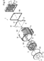
- Fig. 1 shows a sectional view of an embodiment of a magnetic bearing device according to the invention, which is designated overall by the reference numeral 1.
- the magnetic bearing device 1 is designed for the contactless magnetic bearing of a rotor 3, which comprises a disk-shaped or annular magnetically active core 31.
- Fig. 2 another perspective view of the embodiment from Fig. 1 in a perspective exploded view, where Fig. 2 the rotor 3 is not shown.
- the magnetic bearing device 1 is designed according to the temple design and comprises a stator 2, which has a plurality of coil cores 25 - here six coil cores 25 - each of which has a Longitudinal leg 26, which extends from a first end 261 in an axial direction A to a second end 262, and a transverse leg 27 arranged perpendicular to the longitudinal leg 26, which extends in a radial direction that is perpendicular to the axial direction A.
- Each transverse leg 27 is delimited with respect to the radial direction by an end face 271, which forms the pole of the associated coil core 25.
- each longitudinal leg 25 at least one, in this embodiment exactly one, concentrated winding 61 is provided, which encloses the respective longitudinal leg 26.
- the magnetic bearing device 1 comprises a housing 10 in which the coil cores 25 are arranged.
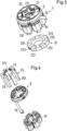
- FIG. 3 and Fig. 4 further representations of the stator 2 of the embodiment of the magnetic bearing device 1, wherein the housing 10 is not shown.
- Fig. 3 shows a perspective view of the stator 2 and a holding device 9, which will be described in more detail.
- a return 22 is provided, which connects all first ends 261 of the longitudinal legs 26 - that is, the ones shown ( Fig. 1 ) lower ends 261 - and serves to guide the magnetic flux.
- the return path 22 is preferably annular.
- Fig. 4 shows a perspective exploded view of the coil cores 25 with the concentrated windings 61 arranged thereon and the holding device 9.
- the housing 10 is preferably made of a metallic material, such as aluminum or stainless steel.
- the housing 10 can be provided with a coating, preferably a plastic coating made of a highly chemically resistant plastic.
- plastics are PTFE (polytetrafluoroethylene), PFA (perfluoroalkoxy polymers), ECTFE (ethylene chlorotrifluoroethylene), ETFE (ethylene tetrafluoroethylene), epoxy resin (polyepoxide), PPA (polyphthalamide), and PE (polyethylene).
- the housing 10 can also be made of titanium or chromium steel.
- the stator 2 further comprises a containment shell 21 with a cup-shaped recess 211 (see also Fig. 11 ), into which the rotor 3 to be supported can be inserted (see Fig. 1 ).
- the containment shell 21 forms one of the two axial ends of the stator 2 or the magnetic bearing device 1, as shown in Fig. 1 the upper axial end of the stator 2.
- a housing cover 11 is arranged, which closes the housing 10.
- the containment shell 21 is firmly connected to the housing 10, for example by means of a positive connection and/or by means of an elastic seal 201.
- the containment shell 21 is hermetically sealed to the housing 10.
- the housing cover 11 is firmly connected to the housing 10, for example by means of screws 111 ( Fig. 1 ), wherein a sealing element 105 is optionally arranged between the housing cover 11 and the housing 10.
- the sealing element 105 can in particular be designed as a flat gasket.
- the housing cover 11 is hermetically sealed to the housing 10.
- the housing 10 is preferably filled with a thermally highly conductive potting compound, for example, an epoxy resin, so that the components arranged inside the housing 10 are surrounded by the potting compound. This reduces the overall thermal resistance and dampens vibrations.
- the housing cover 11 is preferably made of a plastic.
- a chemically resistant plastic such as polypropylene is particularly preferred for applications in chemically aggressive environments.
- the transverse legs 27 of the coil cores 25 are arranged in the containment shell 21 in such a way that the end faces 271 of the transverse legs 27 are arranged around the cup-shaped recess 211.
- the coil cores 25 of the stator 2 are arranged equidistantly on a circular line, so that the end faces 271 surround the magnetically active core 31 of the rotor 3 when the rotor 3 is inserted into the cup-shaped recess 211.
- more than one concentrated winding can be arranged on the longitudinal legs 26.
- more than one concentrated winding can be arranged on the longitudinal legs 26.
- exactly two concentrated windings are provided on each of the longitudinal legs 26, each of which surrounds the respective longitudinal leg 26, wherein the two windings arranged on the same longitudinal leg 26 are arranged adjacent to one another with respect to the axial direction A.
- the concentrated windings 61 serve to generate electromagnetic fields with which the rotor 3 can be magnetically supported in a contactless manner in the cup-shaped recess 211 of the containment shell 21.
- a control unit 40 is provided for controlling and supplying the windings 61 with electrical energy.
- the control unit 40 comprises in particular the Power electronics, such as the converters or rectifiers, which feed the required currents into the windings 61.
- the control unit 40 is in Fig. 1 and in Fig. 2 Particularly preferably, the control unit 40 is also arranged within the housing 10, for example as shown ( Fig. 1 ) below the first ends 261 of the longitudinal legs 26 of the coil cores 25.
- the control unit 40 is preferably also encapsulated with a thermal casting compound or coupled to the housing 10 and the return path 22 and/or the coil cores 25 of the stator 2.
- the control unit 40 preferably comprises an electronics board 41 on which various electronic components 42 are arranged.
- the housing 10 preferably comprises two separate areas arranged adjacent to one another with respect to the axial direction A, one of which forms a stator housing 101 and the other a control housing 102.
- the stator housing 101 of the housing 10 is designed to receive the coil cores 25 with the windings 61 arranged thereon, and the control housing 102 is designed to receive the control unit 40.
- the housing 10 comprises an inner cup 13, which is essentially cylindrical and is arranged radially inward with respect to the windings 61 in the interior space surrounded by the windings 61.
- the inner cup 13 is connected to an outer wall 15 of the housing 10 via a flange-like projection 14.
- the outer wall 15 forms the radially outer boundary of the housing 10.
- the inner cup 13 and the flange-like projection 14 are integral components of the housing 10.
- the outer wall 15, the flange-like projection 14, and the inner cup 13 are configured as a single piece and form the preferably single-piece housing 10.
- the inner cup 13 and the flange-like projection 14 separate the area of the housing 10 which forms the stator housing 101 from the area which forms the control housing 102.
- the inner cup 13 connected to the flange-like projection 14 extends from the radially inner edge of the flange-like projection 14 in the axial direction A and is arranged radially inward with respect to the windings 61 and the return path 22 in the interior space surrounded by the windings 61, as can be seen in particular in Fig. 1 can be seen.
- the inner cup 13 is arranged adjacent to the longitudinal legs 26 of the coil cores 25 and the windings 61 arranged thereon, so that the inner cup 13 can absorb and dissipate the heat generated by the windings 61 and the coil cores 25 particularly well.
- the inner cup 13 extends approximately to the cup-shaped recess 211 of the can 21.
- the stator housing 101 of the housing 10 is designed with an interior space which has a substantially circular or annular cross-sectional area perpendicular to the axial direction A. This is preferred because the stator housing 101 can thereby particularly well accommodate the annular short circuit 22 with the coil cores 25 arranged around the short circuit 22.
- the control housing 102 of the housing 10 is designed with an interior space which has a substantially rectangular or square cross-sectional area perpendicular to the axial direction A. This is preferred because the control housing 102 is thereby particularly well suited to accommodate the preferably rectangular or square electronics board 41 of the control device 40.
- a rectangular or square design of the electronics board 41 is, in particular with regard to production, considerably simpler than, for example, a round design.
- the axial end of the stator 2, at which the containment shell 21 closes the housing 10 has a substantially round cross-section, so that the containment shell 21 has a round or annular configuration.
- the axial end of the stator 2, at which the housing cover 11 closes the housing 10 has a substantially rectangular or square cross-section, so that the housing cover 11 has a rectangular or square configuration.
- the control unit 40 comprises, for example, the electronics board 41, on which the electronic components 42 are provided, e.g., the power electronics for controlling the windings 61.
- the electronics board 41 can also contain, for example, evaluation electronics for evaluating the signals from sensors, e.g., magnetic field sensors, and serve as a communication interface.
- the electronics board 41 is preferably designed as an electronic print or PCB (printed circuit board).
- a connecting cable 45 is provided, which is connected to the electronics board 41 via a cable connection (not shown) or a plug.
- the connecting cable 45 leads out of the housing 10 and serves, for example, to supply power to the magnetic bearing device 1.
- the connecting cable 45 is led out of the housing 20 by means of a sealingly designed cable feedthrough 47.
- the cable feedthrough 47 is preferably designed to be hermetically sealed.
- the electronics board 41 of the control device 40 is connected to the windings 61 via connecting lines (not shown), for example, cables, in order to control them and supply them with energy. It is understood that feedthroughs or openings are provided between the control housing 102 and the stator housing 101, through which the connecting lines are passed. Such feedthroughs can for example, in the flange-like projection 14 or in the inner cup 13.
- the electronics board 41 is preferably arranged directly on the flange-like projection 14, so that the electronics board rests against the flange-like projection 14. This makes it possible to dissipate the heat generated in the control unit 40 via the housing 10 in a particularly efficient manner.
- the main heat sources in the control unit 40 for example, the power switches for the windings 61, are arranged in the areas of the electronics board 41 that rest against the flange-like projection 14.
- the interior of the inner cup 13, i.e. the space enclosed by the inner cup 13, can be used for additional electronic components, electronic boards or connectors or connections. These are Fig. 1 not shown for reasons of clarity.
- the stator 2 is designed such that, in addition to the contactless magnetic bearing of the rotor 3, it can also exert a torque on the rotor 3 or the magnetically active core 31 of the rotor 3, which drives the rotor 3 to rotate about a desired axis of rotation.
- the desired axis of rotation refers to the axis about which the rotor 3 rotates in the operating state when the rotor 3 is in a centered and non-tilted position with respect to the stator 2, as shown in Fig.
- This desired axis of rotation extends in the axial direction A, i.e., in this preferred embodiment, the rotor 3 arranged in the containment shell 21 of the stator 2 can be driven to rotate about the axial direction A.
- the desired axis of rotation coincides with the central axis of the stator 2, which extends in the axial direction A.
- the concentrated windings 61 thus generate electromagnetic rotating fields with which the rotor 3 can be supported magnetically with respect to the stator 2 without contact and can also be driven to rotate about the axial direction A without contact.
- stator 2 has fewer than six, e.g., five or four or three coil cores 25, or in which the stator 2 has more than six, e.g., seven or eight or nine coil cores 25, or any larger number of coil cores 25.
- the rotor 3 comprises the magnetically active core 31, which is ring-shaped or disc-shaped.
- the magnetically active core 31 is, as shown in Fig. 1 as Ring and defines a magnetic center plane.
- the magnetically active core 31 can also be designed as a disk.
- the magnetic center plane is the geometric center plane of the magnetically active core 31 of the rotor 3, which is perpendicular to the axial direction A.
- the magnetically active core 31 is mounted in a radial plane E, which is perpendicular to the axial direction A.
- the radial plane is in Fig. 1 indicated by the line E, which is perpendicular to the axial direction A.
- the radial plane E is therefore the plane which is perpendicular to the axial direction A and contains the line E.
- the radial plane E is the plane in which the magnetically active core 31 of the rotor 3 is actively magnetically mounted between the end faces 271 in the stator 2 in the operating state. If the rotor 3 is not tilted and is not deflected in the axial direction A, the magnetic center plane lies in the radial plane E.
- the radial plane E defines the x-y plane of a Cartesian coordinate system whose z-axis runs in the axial direction A.
- the radial position of the magnetically active core 31 or the rotor 3 refers to the position of the rotor 3 in the radial plane E.
- the rotor 3 can of course also comprise further components such as casings or encapsulations, which are preferably made of a plastic, or of a metal or a metal alloy, or of a ceramic or a ceramic material. Furthermore, the rotor 3 can also have blades for mixing, stirring, or pumping fluids (see, for example, Fig. 12 ) or other components.
- the rotor 3 When the rotor 3 is inserted into the cup-shaped recess 211 of the containment shell 21, the rotor 3, and in particular the magnetically active core 31 of the rotor 3, is surrounded by the radially outwardly arranged end faces 271 of the transverse limbs 27 of the coil cores 25 of the stator 2.
- the transverse limbs 27 thus form a plurality of salient stator poles—here, six stator poles.
- the transverse limbs 27 are arranged at the upper ends of the longitudinal limbs 26 and in the radial plane E. Each transverse limb 27 extends in the radial direction toward the rotor 3.
- the magnetically active core 31 of the rotor 3 When the magnetically active core 31 of the rotor 3 is in its desired position during operation, the magnetically active core 31 is centered between the end faces 271 of the transverse limbs 27, so that the transverse limbs 27 arranged in the radial plane E are also located in the magnetic center plane.
- the concentrated windings 61 are arranged below the radial plane E as shown and are aligned such that their coil axes extend in the axial direction A.
- the return path 22 is preferably designed in a ring shape. Such designs are possible (see e.g. Fig. 1 ), in which the return path 22 extends radially inward along all first ends 261 of the longitudinal legs 26.
- the longitudinal legs 26 of the coil cores 25 carry the windings designed as concentrated windings 61.
- These concentrated windings 61 generate, in the operating state, those electromagnetic rotating fields with which an arbitrarily adjustable transverse force can be exerted in the radial direction on the rotor 3, so that the radial position of the rotor 3, i.e., its position in the radial plane E perpendicular to the axial direction A, can be actively controlled or regulated.
- these electromagnetic rotating fields can also be used to exert a torque on the rotor 3.
- the "magnetically active core 31" of the rotor 3 refers to that region of the rotor 3 which magnetically interacts with the stator 2 for generating the magnetic bearing forces and optionally for torque generation.
- the magnetically active core 31 is annular in this embodiment. Furthermore, the magnetically active core 31 is permanently magnetic.
- the magnetically active core 31 can comprise at least one permanent magnet, but also several permanent magnets, or—as in the embodiment described here—can be made entirely of a permanent magnetic material, so that the magnetically active core 31 is the permanent magnet.
- the magnetically active core 31 is, for example, magnetized in the radial direction.
- Permanent magnets are typically ferromagnetic or ferrimagnetic materials that are magnetically hard, i.e., have a high coercive field strength.
- the coercive field strength is the magnetic field strength required to demagnetize a material.
- a permanent magnet is understood to be a material with a coercive field strength, or more precisely, a coercive field strength of the magnetic polarization, of more than 10,000 A/m.
- the magnetically active core 31 is designed without permanent magnets.
- the rotor 3 is then designed, for example, as a reluctance rotor.
- the magnetically active core 31 of the rotor 3 then consists, for example, of a soft magnetic material.
- Suitable soft magnetic Materials for the magnetically active core 31 are, for example, ferromagnetic or ferrimagnetic materials, in particular iron, nickel-iron, cobalt-iron, silicon-iron, mu-metal.
- the magnetically active core 31 of the rotor 3 comprises both ferromagnetic materials and permanent magnetic materials.
- permanent magnets can be inserted or embedded into a ferromagnetic base body. Such designs are advantageous, for example, when reducing costs for large rotors by saving on permanent magnetic material.
- Both the annular return 22 and the coil cores 25 of the stator 2 are each made of a soft magnetic material because they serve as flux guiding elements for guiding the magnetic flux.
- Suitable soft magnetic materials for the coil cores 25 and the return path 22 are, for example, ferromagnetic or ferrimagnetic materials, i.e., in particular iron, nickel-iron, cobalt-iron, silicon-iron, or mu-metal.
- a preferred embodiment for the stator 2 is a laminated stator core, in which the coil cores 25 and the return path 22 are laminated, i.e., they consist of several thin, stacked sheet elements.
- the coil cores 25 and the return path 22 may consist of pressed and subsequently sintered grains of the aforementioned materials.
- the metallic grains are preferably embedded in a plastic matrix so that they are at least partially insulated from one another, thereby minimizing eddy current losses.
- Soft magnetic composite materials which consist of electrically insulated and pressed metal particles, are therefore also suitable for the stator.
- these soft magnetic composite materials also referred to as SMCs (Soft Magnetic Composites)
- SMCs Soft Magnetic Composites
- SMCs Soft Magnetic Composites
- the magnetically active core 31 of the rotor 3 interacts with the stator 2 in such a way that the rotor 3 can be magnetically supported with respect to the stator 2 without contact and can preferably also be magnetically rotated without contact about the axial direction A. It is particularly advantageous that the same windings 61 with which the magnetic support of the rotor 3 is effected also serve to generate a torque on the rotor 3.
- three degrees of freedom of the rotor 3 are then actively controllable.
- the magnetically active core 31 of the rotor 3 is passively magnetically stabilized, i.e., non-controllably, by reluctance forces.
- the magnetically active core 31 of the rotor 3 is also passively magnetically stabilized.
- the rotor 3 is thus passively magnetically mounted in the axial direction A and against tilting (a total of three degrees of freedom) through the interaction of the magnetically active core 31 with the coil cores 25, or passively magnetically stabilized and actively magnetically mounted in the radial plane (two degrees of freedom).
- an active magnetic bearing also refers to one that is actively controllable or adjustable, for example, via the electromagnetic fields generated by the concentrated windings 61.
- a passive magnetic bearing or passive magnetic stabilization refers to one that is not controllable or adjustable. The passive magnetic bearing or stabilization is based, for example, on reluctance forces, which return the rotor 3 to its desired position in the event of a deflection from its desired position, for example, in the event of a displacement or deflection in the axial direction A or in the event of tilting.
- the magnetic bearing device 1 – and optionally the generation of a torque acting on the rotor – is realized via electromagnetic rotating fields.
- electromagnetic rotating fields For the combined generation of the magnetic bearing forces and a torque for rotating the rotor 3 about the axial direction A, it is possible, on the one hand, to use electromagnetic fields as shown in Fig. 1 shown, to arrange exactly one concentrated winding 61 on each longitudinal leg 26.
- the return path 22 is shown separately from the coil cores 25.
- the return path 22 is essentially ring-shaped and extends in the assembled state (see also Fig. 1 ) radially inwardly along the first ends 261 of the longitudinal legs 26.
- the return path 22 is preferably laminated.
- the return path 22 is constructed from a plurality of thin elements that are stacked parallel to one another in the axial direction A. All elements are identically designed, i.e., each essentially annular and also with the same thickness.
- the back yoke 22 has a plurality of flattened portions 222 on its radially outer circumferential surface, which are planar, i.e., not curved.
- the planar configuration of the flattened portions 222 ensures a large contact area between the back yoke 22 and the longitudinal limbs 26 of the coil cores 25, resulting in particularly good guidance of the magnetic flux and very low magnetic resistance at the transition between the back yoke 22 and the longitudinal limbs 26.
- the flattened portions can also be arranged on separate segments 225, wherein the separate segments 225 are arranged in grooves of the back yoke 22. The grooves are dimensioned so that the separate segments 225 are flush with the rest of the return path 22.
- the number of flats 222 is equal to the number of coil cores 25, so here six flats 222 are provided, which are distributed equidistantly along the outer circumference of the return path 22
- vent holes or recesses 223 can be provided on the return path 22, which extend completely through the return path 22 with respect to the axial direction A. Air can escape through the vent recesses 223, for example, when the housing 20 is filled with a thermally conductive potting compound.
- the magnetic bearing device 1 comprises a plurality - here six - magnetic field sensors 8 (see also Fig. 7 ), which are arranged around the cup-shaped recess 211 in the assembled state of the magnetic bearing device 1.
- the magnetic field sensors 8 are sensors with which a magnetic field can be measured.
- the following sensor types are suitable as magnetic field sensors 8: Hall sensors or magnetoresistive sensors or GMR sensors (GMR: giant magnetoresistance).
- GMR giant magnetoresistance
- all magnetic field sensors 8 are arranged on a circuit board 7 and are signal-connected to it via electrical connections 81, so that all magnetic field sensors 8 can be controlled via the circuit board 7 and the signals measured by the magnetic field sensors 8 can be received and processed via the circuit board 7 or, for example, transmitted to the control device 40.
- the circuit board 7 is arranged with respect to the axial direction A between the windings 61 on the one hand and the transverse legs 27 on the other hand.
- the holding device 9, which is also shown, is designed to receive the circuit board 7.
- the circuit board 7 can be fastened to the holding device 9, for example by means of a plurality of screws 75 (see Fig. 9 ).
- the circuit board 7 is preferably designed as an electronics print or PCB (printed circuit board).
- the magnetic field sensors 8 and the electrical connections 81 are attached to the circuit board 7, for example, by means of a soldered connection.
- Components used for controlling the magnetic field sensors and/or for evaluating the measurement signals detected by the magnetic field sensors 8 can also be provided on the circuit board 7.
- the plate 7 is essentially ring-shaped and arranged parallel to the radial plane E. As shown in Fig. 7 As can be seen, the circuit board 7 is not designed as a closed ring, but rather with a ring-segment-shaped opening 74, so that the circuit board 7 has two ends when viewed in the circumferential direction.
- the circuit board 7 is arranged radially inward with respect to the longitudinal limbs 26 of the coil cores 25, specifically such that the magnetic field sensors 8 are arranged around the cup-shaped recess 211 of the can 21. Particularly preferably, the magnetic field sensors 8 are arranged equidistantly on the circuit board 7 with respect to the circumferential direction.
- the circuit board 7 further comprises an electrical connection element 76, which connects the circuit board 7 to the control device 40, so that the control device 40 and the circuit board 7 can exchange electrical voltages or currents via the electrical connection element 76.
- the electrical connection element 76 is preferably designed as a flex circuit board.
- the electrical connection element 76 can also be designed differently, for example, as a cable, a cable bundle, or a ribbon cable.
- the magnetic bearing device 1 further comprises the holding device 9.
- the holding device 9 serves for a particularly simple and yet precise assembly of the Magnetic bearing device 1 and a very precise positioning of the magnetic field sensors 8 relative to the cup-shaped recess 211 in which the rotor 3 is arranged in the operating state.
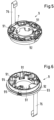
- Fig. 5 shows the holding device 9 in a perspective view, wherein the viewing direction is from the direction of the first ends 261 of the longitudinal legs 26. According to the illustration in Fig. 1 The view from below is directed towards the holding device 9.
- Fig. 6 shows the holding device 9 in a perspective view, with the viewing direction opposite to the viewing direction in Fig. 5 According to the presentation in Fig. 1 So the view into Fig. 6 directed from above onto the holding device 9.
- Both Fig. 5 as well as Fig. 6 show the holding device 9 with the circuit board 7 arranged in the holding device 9.
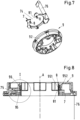
- Fig. 8 shows a sectional view of the holding device 9 with the board 7 inserted therein.
- Fig. 9 another enlarged view of detail I from Fig. 8 .
- the holding device 9 is essentially plate-shaped and annular and comprises several recesses 91 for receiving the transverse legs 27 of the coil cores 25. For each transverse leg 27, exactly one recess 91 is provided, so that the number of recesses 91 is the same as the number of coil cores 25.
- the holding device 9 is inserted into the can 21 (see Fig. 1 ) and extends from the bottom of the containment shell 21 in the axial direction A to a ( Fig. 1 ) lower edge, which is arranged above the windings 61 with respect to the axial direction A as shown.
- the holding device 9 is designed in such a ring-shaped manner that it can be arranged around the cup-shaped recess 211 of the containment shell 21, so that the cup-shaped recess 211 is radially enclosed on the outside by the holding device 9.
- the holding device 9 has an axial edge region 92 which has an outer diameter which is smaller than the diameter of the rest of the holding device 9. According to the illustration in Fig. 6 This axial edge region 92 is the upper axial edge region. The axial edge region 92 ends with respect to the axial direction A at a projection 93, at which the outer diameter of the second holding device 9 increases.
- the design with the axial edge region 92 of smaller diameter and the projection 93 serves to allow the containment shell 21 to enclose the holding device 9 radially on the outside. This is particularly important in Fig. 1
- the containment shell 21 has a radially outer edge 212, which, in the assembled state, encompasses the axial edge region 92 of the second holding device 9.
- the radially outer edge 212 is designed to be so long with respect to the axial direction A that it extends at most to the projection 93.
- the holding device 9 is preferably made of a plastic, and particularly preferably of a plastic that can be processed by injection molding.
- the holding device 9 is thus preferably designed as an injection-molded part.
- Suitable plastics for the production of the holding device 9 include, for example, acrylonitrile butadiene styrene (ABS), polyamide (nylon, PA), polypropylene (PP), or fiber-filled polypropylene.
- the holding device 9 serves both as a holder for the circuit board 7 and as a holder for the magnetic field sensors 8, with which the magnetic field sensors 8 can be positioned very precisely relative to the cup-shaped recess 211.
- a cavity 95 is provided in the holding device 9 for each magnetic field sensor 8, which cavity is delimited with respect to the radial direction by an inner wall 951 and an outer wall 952, wherein the magnetic field sensor 8 can be inserted into the cavity 95, and wherein the cavity 95 is dimensioned such that the inner wall 951 and the outer wall 952 lie flat against the magnetic field sensor 8. This is best achieved in Fig. 9 to recognize.
- both the inner wall 951 and the outer wall 952 of the cavity 95 lie flat against the magnetic field sensor 8, as this allows the position of the magnetic field sensor 8 relative to the cup-shaped recess 211 to be known with very high accuracy.
- the magnetic field sensors 8 are preferably rectangular in shape.
- the cavity 95 is dimensioned such that the magnetic field sensor 8 can be fully inserted into the cavity 95 with respect to the axial direction A.
- the cavity 95 thus forms a pocket for the magnetic field sensor 8, which is at least as deep with respect to the axial direction A as the extension of the magnetic field sensor 8 in the axial direction A.
- the width of this pocket in the radial direction i.e.
- the distance measured in the radial direction between the inner wall 951 and the outer wall 952 is dimensioned such that it corresponds to the extension of the magnetic field sensor 8 in the radial direction, so that the magnetic field sensor 8 can be pushed into the cavity 95 in the axial direction and then the inner wall 951 and the outer wall 952 of the cavity 95 lie flat against the magnetic field sensor 8.
- the inner wall 951 and/or the outer wall 952 slightly oblique to the axial direction, so that the cavity 95 is slightly conical when viewed in the axial direction A, wherein the cavity 95 is slightly conical with respect to the illustration in Fig. 9 tapered towards the top.
- each magnetic field sensor 8 is arranged as close as possible to the cup-shaped recess 211.
- the inner diameter of the holding device 9 is dimensioned such that it is the same size as or only very slightly larger than the outer diameter DA ( Fig. 11 ) of the cup-shaped recess 211 of the containment shell 21.
- the wall of the holding device 9, which forms the inner walls 951 of the cavities 95 rests against the cup-shaped recess 211 of the containment shell 21.
- the inner wall 951, which delimits the cavity 95 is arranged between the cup-shaped recess 211 of the containment shell 21 and the magnetic field sensor 8.
- the six cavities 95 for the six magnetic field sensors 8 are also preferably arranged equidistantly with respect to the circumferential direction of the holding device 9. Particularly preferably, exactly one cavity 95 is arranged between each two circumferentially adjacent recesses 91. In the assembled state, each magnetic field sensor 8 is then arranged between each two circumferentially adjacent coil cores 25.
- FIG. 9 an embodiment is shown in which the guide element 96 forms the outer wall 952 of the cavity 95.
- FIG. 10 another perspective view of the separate guide element 96 from Fig. 9 . Since such a separate guide element 96 is provided for each cavity 95, there are therefore six such guide elements 96 in this embodiment.
- the separate guide elements 96 are separate components, i.e., components separate from the holding device 9, which are only inserted into the holding device 9 after the holding device 9 has been manufactured, in order to thus form the cavities 95 for the magnetic field sensors 8. Since the guide elements 96 are separate components, they can be manufactured with very high precision, which is advantageous for the accuracy of the position of the magnetic field sensors 8. In addition, the separate guide elements 96 make it particularly easy to adapt the dimensions of the cavity 95 to the respective magnetic field sensors 8.
- each separate guide element 96 has an L-shaped profile.
- the separate guide element 96 has a bottom 961 ( Fig. 10 ), which forms the short leg of the L, and a side wall 962, which forms the long leg of the L.
- the bottom 961 of the guide element 96 also forms the bottom of the cavity 95.
- the side wall 962 of the guide element 96 forms the outer wall 952, which delimits the cavity 95.
- the side wall 962 comprises two parallel guides 963, between which the magnetic field sensor 8 is inserted when the guide element 96 is inserted into the holding device 9.
- the two parallel guides 963 are spaced apart by a distance D1 that corresponds to the corresponding extension of the magnetic field sensor 8, so that the magnetic field sensor 8 can be inserted between the two guides 963 and is guided by the guides 963.
- the two guides 963 have a length L, which, when inserted, is the extension of the guides 963 in the axial direction.
- the length L is dimensioned such that it is at least as large as the corresponding dimension of the magnetic field sensor 8, so that the magnetic field sensor 8 does not protrude beyond the guide element 96 with respect to the axial direction A.
- the holding device 9 in the embodiment described here is designed such that it can accommodate the circuit board 7 with the magnetic field sensors 8 arranged thereon.
- the holding device 9 comprises an annular edge 97 ( Fig. 9 ) with a shoulder 98 provided thereon, the shoulder 98 being arranged radially inward with respect to the edge 97.
- the shoulder 98 is designed and arranged such that the circuit board 7 can be placed on the shoulder 98 and rests against this shoulder 98.
- the circuit board 7 can be fastened to the shoulder 98 and thus to the holding device 9 with a plurality of screws 75.
- the edge 97 is designed such that it projects beyond the circuit board 7 with respect to the axial direction A. This has the advantage that the entire holding device 9 can then be cast with a potting compound and the circuit board is completely covered by the potting compound.
- Fig. 11 shows a sectional view of the containment shell 21 of the stator 2 of the embodiment of the magnetic bearing device, the section being taken in the axial direction A.
- the containment shell 21 with the cup-shaped recess 211 is preferably designed as a single piece.
- the containment shell 21 is preferably made of a plastic, and particularly preferably of a plastic that can be processed by injection molding.
- the containment shell 21 is thus preferably designed as an injection-molded part.
- Suitable plastics for the manufacture of the containment shell 21 are, for example, acrylonitrile butadiene styrene (ABS), polyamide (nylon, PA), polypropylene (PP), polytetrafluoroethylene (PTFE), perfluoroalkoxy alkanes (PFA), polyvinyl chloride (PVC), polybutylene terephthalate (PBT), polyimide (PI), polyetheretherketone, polysuccinimide (PSI), polyphthalamide (PPA), or polyether ether ketone (PEEK).
- ABS acrylonitrile butadiene styrene
- PP polyamide
- PP polypropylene
- PTFE polytetrafluoroethylene
- PFA perfluoroalkoxy alkanes
- PVC polyvinyl chloride
- PBT polybutylene terephthalate
- PI polyimide
- PESI polyetheretherketone
- PSI polysuccinimide
- the containment shell 21 comprises the cup-shaped recess 211, into which the rotor 3 can be inserted, and the radially outer edge 212, which in the assembled state encompasses the axial edge region 92 of the holding device 9.
- Assembly can be carried out, for example, as follows: The circuit board 7 with the magnetic field sensors 8 arranged and secured thereon is inserted into the holding device 9. To do this, first insert each of the magnetic field sensors 8 into one of the cavities 95, and then the circuit board 7 is placed onto the shoulder 98 of the holding device 9. Optionally, the circuit board 7 is attached to the holding device 9 with the screws 75.
- the holding device 9 is completely filled with a first potting compound such that the circuit board 7 is completely covered by the first potting compound.
- This first potting compound is preferably a soft potting compound.
- a soft potting compound means a potting compound that has a Shore D hardness of less than 40. Silicones or polyurethanes, for example, are suitable as the first potting compound.
- the coil cores 25 are guided through the recesses 91 in the holding device 9 and through the concentrated windings 61.
- the magnetic return path 22 is arranged between the first ends 261 of the longitudinal legs 26.
- the holding device 9, the return path 22 and the coil cores 25 with the concentrated windings 61 arranged thereon are arranged in a first installation direction in the axial direction A (as shown in Fig. 2 from the left side) into the stator housing 101 of the housing 10.
- the electrical connecting element 76 is guided parallel to the longitudinal legs 26 of the coil cores 25 through the stator housing 101 into the control housing 102.
- the containment shell 21 is placed on the housing 10 and connected to the housing 10 in a sealing, preferably hermetically sealed, manner, the seal 201 being arranged between the containment shell 21 and the housing 10.
- the housing 10 of the magnetic bearing device 1 is filled with a thermally conductive potting compound.
- a second potting compound is used for this purpose, which is highly thermally conductive and which is different from the first. Potting compound.
- the second, thermally conductive potting compound is preferably harder than the first.
- the second thermal potting compound should have particularly good thermal conductivity to quickly and reliably dissipate the heat generated during operation into the housing, from where the heat is then dissipated primarily by convection.
- Polyurethanes, epoxy resins, acrylic resins, or polyesters are suitable as second, thermally conductive potting compounds.
- control unit 40 is inserted into the control housing 102 of the housing 10 in a second installation direction, wherein the second installation direction is opposite to the first installation direction. As shown in Fig. 2 The control unit 40 is inserted into the control housing 102 from the right. The electrical connecting element 76 is connected to the control unit 40.
- the housing cover 11 When the control unit 40 is arranged in the control housing 102 of the housing 10, the housing cover 11 is placed on the housing 10 and connected to the housing 10 in a sealing, preferably hermetically sealed manner, with the sealing element 105 being arranged between the housing cover 11 and the housing 10.
- the housing cover 11 is secured, for example, by means of several screws 111 ( Fig. 1 ) attached to the housing 10.
- control housing 102 of the housing 10 can also be encapsulated with a potting compound, for example, for applications with highly corrosive, aggressive, or explosive fluids. If the control housing is also encapsulated, this is done before the housing cover 11 is placed on the housing 10 and firmly connected to it.
- the invention further proposes a centrifugal pump 100 for conveying a fluid, which is characterized in that the centrifugal pump 100 comprises a magnetic bearing device 1 and a rotor 3, wherein the magnetic bearing device 1 is configured according to the invention.
- the magnetic bearing device 1 is configured such that, in addition to the contactless magnetic bearing of the rotor 3, it can generate a torque acting on the rotor 3 that drives its rotation about the axial direction A.
- Fig. 12 shows an embodiment of a centrifugal pump according to the invention, which is designated overall by the reference numeral 100, in a schematic sectional view in a section in the axial direction A.
- the housing 10 and the containment shell 21 are not shown.
- the centrifugal pump 100 comprises a pump unit 50 with a pump housing 51, which comprises an inlet 52 and an outlet 53 for the fluid to be pumped, wherein the Rotor 3 is arranged in pump housing 51 and comprises a plurality of vanes 54 for conveying the fluid.
- the pump unit 50 is designed such that the pump unit 50 can be inserted into the containment shell 21 of the stator 2 such that the magnetically active core 31 of the rotor 3 is surrounded by the end faces 271 of the transverse legs 27.
- the rotor 3 is designed as an integral rotor because it serves as both the rotor 3 of the magnetic bearing and the rotor 3 of the centrifugal pump 100, which is used to pump the fluid.
- This design as an integral rotor offers the advantage of a very compact and space-saving design.
- the stator 2 is in the housing 10 (in Fig. 12 (not shown) is arranged, which is preferably designed together with the containment shell 21 as a hermetically sealed housing 10.
- the control unit 40 is preferably, but not necessarily, also arranged in the housing 10.
- the housing 10 is preferably filled with a potting compound, for example with an epoxy resin, an acrylic resin, a polyester, or a polyurethane, so that all components arranged inside the housing 20 are surrounded by the potting compound.
- the pump unit 50 is in the cup-shaped recess 211 of the containment shell 21 (in Fig. 12 not shown) so that the rotor 3 provided in the pump housing 51 is surrounded by this cup-shaped recess 211, the magnetically active core 31 of the rotor 3 being arranged between the transverse legs 27 of the coil cores 26.
- the pump housing 51 is fixed to the housing 20, preferably with a plurality of screws (not shown).
- the rotor 3 comprises a plurality of vanes 54 for conveying the fluid. In the exemplary embodiment described here, for example, a total of four vanes 54 are provided, this number being exemplary.
- the rotor 3 further comprises a casing 38, with which the magnetically active core 31 of the rotor 3 is enclosed and preferably hermetically encapsulated, so that the magnetically active core 31 of the rotor 3 does not come into contact with the fluid to be conveyed. All vanes 54 are arranged on the casing 38 and are arranged equidistantly with respect to the circumferential direction of the rotor 3. Each vane 54 extends radially outward and is connected to the casing 38 in a rotationally fixed manner.
- the vanes 54 can be separate components that are then fixed to the casing 38. It is of course also possible for all vanes 54 to be an integral part of the casing 38, i.e., for the casing 38 to be formed integrally with all vanes 54.
- the rotor 3 with the vanes 54 forms the impeller or impeller of the centrifugal pump 100, which acts on the fluid or fluids.
- the pump housing 51 of the pump unit 50 as well as the casing 38 and the vanes 54 are made of one or more plastics.
- Suitable plastics are: polyethylene (PE), low-density polyethylene (LDPE), ultra-low-density polyethylene (ULDPE), ethylene-vinyl acetate (EVA), polyethylene terephthalate (PET), polyvinyl chloride (PVC), polypropylene (PP), polyurethane (PU), polyvinylidene fluoride (PVDF), acrylonitrile butadiene styrene (ABS), polyacrylic, polycarbonate (PC), polyetheretherketone (PEEK) or silicone.
- PE polyethylene
- LDPE low-density polyethylene
- ULDPE ultra-low-density polyethylene
- EVA ethylene-vinyl acetate
- PET polyethylene terephthalate
- PVC polyvinyl chloride
- PP polypropylene
- PU polyurethane
- the magnetic bearing device 1 according to the invention is also suitable for devices other than centrifugal pumps, for example for mixing devices for mixing flowable substances, for stirring devices, for example for mixing a fluid in a tank, for fans or also for devices for carrying and rotating wafers, for example in semiconductor production.
Landscapes
- Engineering & Computer Science (AREA)
- General Engineering & Computer Science (AREA)
- Mechanical Engineering (AREA)
- Physics & Mathematics (AREA)
- Electromagnetism (AREA)
- Power Engineering (AREA)
- Connection Of Motors, Electrical Generators, Mechanical Devices, And The Like (AREA)
- Magnetic Bearings And Hydrostatic Bearings (AREA)
- Structures Of Non-Positive Displacement Pumps (AREA)
- Permanent Magnet Type Synchronous Machine (AREA)
Abstract
Description
- Die Erfindung betrifft einen Magnetlagervorrichtung gemäss dem Oberbegriff des unabhängigen Patentanspruchs und eine Zentrifugalpumpe mit einer solchen Magnetlagervorrichtung.
- Magnetlagervorrichtungen zur berührungslos magnetischen Lagerung eines Rotors haben den Vorteil, dass sie ohne mechanische Lager für den Rotor auskommen. Der Rotor wird mittels magnetischer Kräfte gelagert bzw. stabilisiert, die von einem Stator der Magnetlagervorrichtung generiert werden. Aufgrund der Abwesenheit von mechanischen Lagern eignen sich solche Magnetlagervorrichtungen insbesondere für Pump-, Misch-, Zentrifugier- oder Rührvorrichtungen, mit denen sehr empfindliche Substanzen gefördert werden, beispielsweise Blutpumpen, oder bei denen sehr hohe Anforderungen an die Reinheit gestellt werden, beispielsweise in der pharmazeutischen Industrie oder in der biotechnologischen Industrie, oder mit denen abrasive oder aggressive Substanzen gefördert werden, welche mechanische Lager sehr schnell zerstören würden, beispielsweise Pumpen oder Mischer für Slurry, Schwefel-, Phosphorsäure oder andere Chemikalien in der Halbleiterindustrie.
- In der biotechnologischen Industrie werden solche Magnetlagervorrichtungen beispielsweise im Zusammenhang mit Bioreaktoren eingesetzt, z. B. bei Zentrifugalpumpen zum Fördern der Fluide in den oder aus dem Bioreaktor, oder bei Mischvorrichtungen, welche die Fluide in dem Bioreaktor durchmischen. In der Halbleiterindustrie werden solche Magnetlagervorrichtung nicht nur für das Fördern aggressiver oder abrasiver Substanzen verwendet, sondern beispielsweise auch für Rotationsvorrichtungen, mit denen Wafer rotiert werden.
- Auch ist es bekannt, Magnetlagervorrichtungen für Viskosimeter zu verwenden.
- Eine vorteilhafte und an sich bekannte Ausführungsform einer Magnetlagervorrichtung ist die Ausführung in Tempelbauweise, auf die sich auch die vorliegende Erfindung bezieht.
- Das Charakteristische der Tempelbauweise ist es, dass der Stator der Magnetlagervorrichtung eine Mehrzahl von Spulenkernen aufweist, von denen jeder einen Längsschenkel umfasst, der sich von einem ersten Ende in einer axialen Richtung bis zu einem zweiten Ende erstreckt. Mit der axialen Richtung ist dabei diejenige Richtung gemeint, welche durch die Solldrehachse des Rotors definiert ist, welcher mit der Magnetlagervorrichtung gelagert wird. Die Solldrehachse ist diejenige Drehachse, um welche der Rotor im Betriebszustand rotiert, wenn er bezüglich des Stators in einer zentrierten und unverkippten Position ist. Jeder Spulenkern umfasst zusätzlich zu dem Längsschenkel einen Querschenkel, welcher jeweils an dem zweiten Ende des Längsschenkels angeordnet ist, und welcher sich in radialer Richtung - üblicherweise nach innen - erstreckt, wobei die radiale Richtung senkrecht zur axialen Richtung ist. Der Querschenkel erstreckt ich also im Wesentlichen rechtwinklig zum Längsschenkel. Die Spulenkerne haben jeweils die Form eines L, wobei die Querschenkel die kurzen Schenkel des L bilden. Der zu lagernde Rotor ist dann zwischen den Querschenkeln angeordnet.
- Die Mehrzahl der Längsschenkel, die sich in axialer Richtung erstrecken und an die Säulen eines Tempels erinnern, hat dieser Bauweise ihren Namen gegeben.
- In einer Ausführungsform hat der Stator der Magnetlagervorrichtung beispielsweise sechs Spulenkerne, die kreisförmig und äquidistant um eine becherförmige Ausnehmung herum angeordnet sind, in welche der Rotor eingesetzt werden kann. Die ersten Enden der Längsschenkel sind üblicherweise in Umfangsichtung durch einen Rückschluss verbunden, welcher der magnetischen Flussführung dient. Der zu lagernde Rotor umfasst einen magnetisch wirksamen Kern, beispielsweise eine permanentmagnetische Scheibe oder einen permanentmagnetischen Ring, der zwischen den radial innenliegenden Enden der Querschenkel angeordnet ist und im Betriebszustand um die axiale Richtung rotiert, wobei der Rotor berührungslos magnetisch bezüglich des Stators gelagert ist.
- Für solche Magnetlagervorrichtungen ist es nicht notwendiger Weise so, dass der magnetisch wirksame Kern des Rotors permanentmagnetisch ausgestaltet sein muss. Es sind auch solche Ausgestaltungen bekannt, bei denen der magnetisch wirksame Kern des Rotors permanentmagnetfrei, also ohne Permanentmagnete ausgestaltet ist. Der magnetisch wirksame Kern des Rotors ist dann beispielsweise ferromagnetisch ausgestaltet und besteht beispielsweise aus Eisen, Nickel-Eisen, Kobalt-Eisen, Silizium-Eisen, Mu-Metall oder einem anderen ferromagnetischen Werkstoff.
- Ferner sind Ausgestaltungen möglich, bei denen der magnetisch wirksame Kern des Rotors sowohl ferromagnetische Materialien als auch permanentmagnetische Materialien umfasst. Beispielsweise können Permanentmagnete in einen ferromagnetischen Grundkörper eingelegt bzw. eingesetzt werden. Solche Ausgestaltungen sind z.B. vorteilhaft, wenn man bei grossen Rotoren die Kosten durch Einsparen von permanentmagnetischem Material reduzieren will.
- Um die für die berührungslos magnetische Lagerung des Rotors notwendigen elektromagnetischen Felder zu erzeugen, tragen die Längsschenkel Wicklungen. Die Wicklungen sind beispielsweise so ausgestaltet, dass um jeden Längsschenkel herum eine konzentrierte Wicklung gewickelt ist, das heisst, die Spulenachse jeder konzentrierten Wicklung erstreckt sich jeweils in axialer Richtung. Dabei ist es typisch für die Tempelbauweise, dass die Spulenachsen der konzentrierten Wicklungen in der axialen Richtung verlaufen und, dass die konzentrierten Wicklungen nicht in der radialen Ebene angeordnet sind, in welcher der Rotor bzw. der magnetisch wirksame Kern des Rotors im Betriebszustand gelagert wird.
- Es sind Ausgestaltungen möglich, bei denen auf jedem Längsschenkel genau eine konzentrierte Wicklung angeordnet ist. In anderen Ausgestaltungen sind auf jedem Längsschenkel mehrere, beispielsweise genau zwei konzentrierte Wicklungen vorgesehen. Auch sind Ausgestaltungen möglich, bei denen Wicklungen vorgesehen sind, die um zwei in Umfangsrichtung benachbarte Längsschenkel herum gewickelt sind, sodass sich diese beiden benachbarten Längsschenkel beide im Innenraum der konzentrierten Wicklung befinden.
- Für eine zuverlässige und sichere berührungslos magnetische Lagerung des Rotors ist es sehr wichtig, die jeweils aktuelle Position des Rotors in der radialen Ebene mit hoher Genauigkeit zu kennen, sodass die Lage des Rotors in der radialen Ebene auf eine Sollposition geregelt werden kann. Zur Bestimmung der Position des Rotors ist es bekannt, beispielsweise aus der
WO 2014/036419 , eine Mehrzahl von Magnetfeldsensoren, beispielsweise Hall-Sensoren, in der Magnetlagervorrichtung so anzuordnen, dass sie um den magnetisch wirksamen Kern des Rotors herum angeordnet sind. Aus den Signalen der Magnetfeldsensoren wird dann die aktuelle Position des Rotors möglichst genau ermittelt. Da die Magnetfeldsensoren aber alle Magnetfelder an ihrer jeweiligen Position erfassen, also beispielsweise auch das Statormagnetfeld, ist es oft sehr schwierig, die genaue Position des Rotors in der radialen Ebene aus den Signalen der Magnetfeldsensoren zu ermitteln. - Ausgehend von diesem Stand der Technik ist es daher eine Aufgabe der Erfindung, eine Magnetlagervorrichtung zur berührungslos magnetischen Lagerung eines Rotors mit einem ring- oder scheibenförmigen magnetisch wirksamen Kern vorzuschlagen, bei welcher die Position des Rotors mittels Magnetfeldsensoren zuverlässig und mit sehr hoher Genauigkeit ermittelt werden kann. Ferner ist es eine Aufgabe der Erfindung, eine Zentrifugalpumpe mit einer solchen Magnetlagervorrichtung vorzuschlagen.
- Der diese Aufgabe lösende Gegenstand der Erfindung ist durch die Merkmale des unabhängigen Patentanspruchs gekennzeichnet.
- Erfindungsgemäss wird also ein Magnetlagervorrichtung vorgeschlagen zur berührungslos magnetischen Lagerung eines Rotors, der einen scheibenförmigen oder ringförmigen magnetisch wirksamen Kern umfasst, wobei die Magnetlagervorrichtung einen Stator aufweist, welcher eine Mehrzahl von Spulenkernen umfasst, von denen jeder einen Längsschenkel umfasst, welcher sich von einem ersten Ende in einer axialen Richtung bis zu einem zweiten Ende erstreckt, sowie einen Querschenkel, welcher an dem zweiten Ende des Längsschenkels angeordnet ist, und sich in einer radialen Richtung erstreckt, die senkrecht zur axialen Richtung ist, wobei an jedem Längsschenkel mindestens eine konzentrierte Wicklung vorgesehen ist, welche den jeweiligen Längsschenkel umgibt, wobei der Stator ferner eine becherförmige Ausnehmung aufweist, in welche der Rotor einsetzbar ist, wobei die becherförmige Ausnehmung an einem axialen Ende des Stators angeordnet ist, wobei die Querschenkel um die becherförmige Ausnehmung herum angeordnet sind, und wobei eine Mehrzahl von Magnetfeldsensoren zur Bestimmung der Position des Rotors um die becherförmigen Ausnehmung herum angeordnet ist. Es ist eine ringförmige Halteeinrichtung für die Magnetfeldsensoren vorgesehen, welche für jeden Magnetfeldsensor eine Kavität aufweist, die bezüglich der radialen Richtung von einer innenliegenden Wand und von einer aussenliegenden Wand begrenzt wird, wobei der Magnetfeldsensor in die Kavität einschiebbar ist, und wobei die Kavität so dimensioniert ist, dass die innenliegende Wand und die aussenliegende Wand flächig an dem Magnetfeldsensor anliegen.
- Dadurch, dass eine ringförmige Halterung vorgesehen ist, die für jeden Magnetfeldsensor eine Kavität aufweist, die so dimensioniert ist, dass die innenliegende Wand und die aussenliegende Wand flächig an dem Magnetfeldsensor anliegen, ist die jeweilige Position des Magnetfeldsensors mit einer äusserst hohen Genauigkeit bekannt. Insbesondere die Position der Magnetfeldsensoren relativ zu der becherförmigen Ausnehmung ist mit hoher Genauigkeit bekannt, was eine sehr genaue Bestimmung der Position des Rotors in der becherförmigen Ausnehmung ermöglicht. Insbesondere ist die Position des jeweiligen Magnetfeldsensors nur durch die Lage der Kavität definiert und hängt nicht davon ab, wie beispielsweise der Magnetfeldsensor auf einer Platine festgelötet ist oder an einer Struktur festgeklebt ist. Wenn die Position eines Magnetfeldsensors auch durch solche Verbindungen wie Löten oder Kleben bestimmt wird, so resultiert hieraus in aller Regel eine Ungenauigkeit der Platzierung, welche sich negativ auf die Genauigkeit der Positionsbestimmung des Rotors auswirkt. Da bei der erfindungsgemässen Ausgestaltung Löt- oder Klebeverbindungen die Position des Magnetfeldsensors nicht beeinflussen können, resultiert eine sehr hohe Genauigkeit der Bestimmung der Rotorposition.
- Gemäss einer bevorzugten Ausgestaltung ist bezüglich der axialen Richtung zwischen den Wicklungen und den Querschenkeln eine Platine angeordnet, auf welcher alle Magnetfeldsensoren angeordnet sind, und die Halteeinrichtung ist zum Aufnehmen der Platine ausgestaltet. Das hat den Vorteil, dass zunächst alle Magnetfeldsensoren mit der Platine verbunden werden können, wobei die elektrischen Verbindungen zum Ansteuern der Magnetfeldsensoren und zum Empfangen der Messsignale auf der Platine hergestellt werden. Anschliessend wir dann die Platine mit den mit ihr verbundenen Magnetfeldsensoren in die Halteeinrichtung eingesetzt, wobei die Magnetfeldsensoren in die Kavitäten eingeschoben werden. Schliesslich wird die Platine fest mit der Halteeinrichtung verbunden, beispielsweise mittels Schrauben und/oder mittels einer Vergussmasse, mit welcher die Halteinrichtung ausgegossen wird.
- Dabei ist es bevorzugt, dass die Halteeinrichtung einen ringförmigen Rand mit einem daran vorgesehen Absatz aufweist, wobei der Absatz radial innenliegend bezüglich des Rands angeordnet ist, und wobei die Platine an dem Absatz anliegt. Dieser Absatz bildet also eine Auflage für die Platine, sodass diese in sehr einfacher Weise in der Halteeinrichtung platziert werden kann.
- Ferner ist es bevorzugt, dass der Rand derart ausgestaltet ist, dass er die Platine bezüglich der axialen Richtung überragt. Durch diese Massnahme ist es möglich, die Halteeinrichtung mit einer Vergussmasse auszugiessen, wobei die Platine vollständig von der Vergussmasse überdeckt wird.
- Gemäss einer bevorzugten Ausführungsform weist die Halteeinrichtung für jeden Spulenkern eine separate Aussparung auf, welche den Spulenkern umschliesst und den Querschenkel des Spulenkerns aufnimmt.
- Hierbei ist es vorteilhaft, dass jede Kavität bezüglich der Umfangsrichtung zwischen zwei benachbarten Aussparungen angeordnet ist. Dadurch ist es möglich, dass jeder Magnetfeldsensor bezüglich der Umfangsrichtung jeweils zwischen zwei benachbarten Spulenkernen angeordnet ist.
- Gemäss einer besonders bevorzugten Ausführungsform sind bei der Magnetlagervorrichtung genau sechs Spulenkerne vorgesehen.
- Ferner ist es bevorzugt, dass die Magnetlagervorrichtung genau sechs Magnetfeldsensoren umfasst, die vorzugsweise äquidistant um die becherförmige Ausnehmung herum angeordnet sind.
- In einer bevorzugten Ausgestaltung ist die Halteeinrichtung mit einer ersten Vergussmasse aufgefüllt, derart, dass die Platine vollständig von der Vergussmasse bedeckt ist. Die erste Vergussmasse ist besonders bevorzugt eine weiche Vergussmasse. Mit einer weichen Vergussmasse ist im Rahmen dieser Anmeldung eine Vergussmasse gemeint, welche eine Shore-Härte D von weniger als 40 aufweist. Als erste Vergussmasse ist beispielsweise ein Silikon oder ein Polyurethan geeignet.
- Gemäss einer besonders bevorzugten Ausgestaltung sind die Spulenkerne mit den darauf angeordneten Wicklungen in einem Gehäuse angeordnet, welches mit einer zweiten Vergussmasse ausgegossen, wobei die zweite Vergussmasse eine thermisch leitfähige Vergussmasse ist, Diese zweite, thermisch leitfähige Vergussmasse ist eine harte thermische Vergussmasse, beispielsweise ein Epoxidharz. Folglich sind die erste Vergussmasse und die zweite, thermische Vergussmasse verschieden voneinander. Während des Betriebs der Magnetlagervorrichtung können insbesondere im Bereich der Halteeinrichtung mit den darin angeordneten Magnetfeldsensoren stärkere und häufige Temperaturschwankungen auftreten. Gegen solche ist eine weiche Vergussmasse besser beständig. Daher ist für das Ausgiessen der Halteeinrichtung eine weiche Vergussmasse bevorzugt, die weicher ist als die harte Vergussmasse, mit welcher das Gehäuse ausgegossen ist. Die zweite Vergussmasse, welche insbesondere die Spulenkerne und die darauf angeordneten Wicklungen umschliesst, weist bevorzugt eine besonders gute thermische Leitfähigkeit auf, um die generierte Wärme, z. B. die durch Kupferverluste und Eisenverluste generierte Wärme, möglichst effizient abzuführen. Um eine hohe thermische Leitfähigkeit zu erreichen, werden der zweiten, thermischen Vergussmasse vorzugsweise thermisch gut leitende Füllstoffe beigemischt, beispielsweise Graphit Pulver, Kohlefasern, Carbon-Nanotubes, Aluminiumoxid Pulver, Bornitrid Pulver oder andere Keramik Pulver. Diese Füllstoffe verbessern die thermische Leitfähigkeit, bewirken aber auch eine höhere Härte der ausgehärteten Vergussmasse. Daher weist die zweite, thermische Vergussmasse eine grössere Härte, insbesondere eine grössere Shore-Härte D auf als die erste Vergussmasse.
- Im Hinblick auf eine möglichst genaue Positionierung der Magnetfeldsensoren ist es vorteilhaft, dass für jede Kavität jeweils ein separates Führungselement vorgesehen ist, welches die innenliegende Wand oder die aussenliegende Wand bildet, durch welche die Kavität begrenzt wird. Solche separaten Führungselemente lassen sich üblicherweise einfacher mit einer sehr hohen Präzision herstellen als die gesamte Halteeinrichtung, die beispielsweise mittels eines Spritzgiessverfahren hergestellt wird. Zur Bildung der Kavität für den Magnetfeldsensor wird das separate Führungselement in axialer Richtung in eine dafür vorgesehene Ausnehmung der Halteeinrichtung eingeführt, sodass es anschliessend die innenliegende Wand oder die aussenliegende Wand bildet, welche die Kavität bezüglich der radialen Richtung begrenzen. Vorzugsweise ist das separate Führungselement formschlüssig, beispielsweise mittels eines Presssitzes, mit der Halteeinrichtung verbunden.
- Vorzugsweise weist der Stator einen Spalttopf auf, welcher ein axiales Ende des Stators bildet, wobei der Spalttopf die becherförmige Ausnehmung aufweist, in welche der Rotor einsetzbar ist, und wobei der Spalttopf die Halteeinrichtung radial aussenliegend umfasst. Bei dieser bevorzugten Ausgestaltung ist der Spalttopf vorzugsweise als separater Spalttopf ausgebildet, welcher die becherförmige Ausnehmung aufweist. Insbesondere aus konstruktiven Gründen ist es bevorzugt, dass der Spalttopf die zweite Halteeinrichtung radial aussenliegend umfasst. Dabei ist ein axialer Endbereich der zweiten Halteeinrichtung innerhalb des Spalttopfes angeordnet und wird von diesem in Umfangsrichtung gesehen vollständig umschlossen.
- Vorzugsweise ist die Halteeinrichtung aus einem Kunststoff hergestellt. Beispielsweise ist die Halteeinrichtung als Spritzgussteil ausgestaltet, das in einem Spritzgiessverfahren hergestellt wird.
- Ferner ist es bevorzugt, dass der Spalttopf aus einem Kunststoff hergestellt ist. Auch der Spalttopf kann als Spritzgussteil ausgestaltet sein.
- Gemäss einer bevorzugten Ausführungsform hat die Magnetlagervorrichtung ein Gehäuse, welches ein Statorgehäuse und ein Kontrollgehäuse umfasst, welche bezüglich der axialen Richtung benachbart zueinander angeordnet sind, wobei das Statorgehäuse zur Aufnahme der Spulenkerne mit den darauf angeordneten konzentrierten Wicklungen ausgestaltet ist, und das Kontrollgehäuse zur Aufnahme einer Kontrolleinheit für die Ansteuerung und die Versorgung der Wicklungen mit elektrischer Energie zur Erzeugung elektromagnetischer Felder.
- Vorzugsweise ist das Gehäuse derart ausgestaltet, dass die Spulenkerne mit den darauf angeordneten konzentrierten Wicklungen in einer ersten Einbaurichtung in axialer Richtung in das Statorgehäuse einführbar sind, und die Kontrolleinheit in einer zweiten Einbaurichtung in das Kontrollgehäuse einführbar ist, wobei die erste Einbaurichtung entgegengesetzt zur zweite Einbaurichtung gerichtet ist. Dabei hat das Gehäuse vorzugsweise zwei voneinander getrennte Bereiche, von denen einer das Statorgehäuse bildet und der andere das Kontrollgehäuse. Diese beiden Bereiche können beispielsweise durch eine Wand voneinander getrennt sein, welche Durchlässe, z.B. für elektrische Verbindungen aufweist. Das Gehäuse ist dann bezüglich der Umfangsrichtung vorzugsweise einstückig ausgestaltet.
- Gemäss einer besonders bevorzugten Ausführungsform ist der Stator der Magnetlagervorrichtung zur Erzeugung eines Drehmoments ausgestaltet, mit welchem der Rotor berührungslos magnetisch zur Rotation um die axiale Richtung antreibbar ist.
- Durch die Erfindung wird ferner eine Zentrifugalpumpe zum Fördern eines Fluids vorgeschlagen, die eine erfindungsgemässe Magnetlagervorrichtung umfasst, sowie einen Rotor mit einem magnetisch wirksamen Kern, wobei der Rotor in die becherförmige Ausnehmung des Spalttopfes einsetzbar ist, und wobei der Rotor als Rotor der Zentrifugalpumpe ausgestaltet ist.
- Weitere vorteilhafte Massnahmen und Ausgestaltungen der Erfindung ergeben sich aus den abhängigen Ansprüchen.
- Im Folgenden wird die Erfindung anhand von Ausführungsbeispielen und anhand der Zeichnung näher erläutert. In der Zeichnung zeigen:
- Fig. 1:
- eine Schnittdarstellung eines Ausführungsbeispiels einer erfindungsgemässen Magnetlagervorrichtung,
- Fig. 2:
- eine perspektivische Darstellung des Ausführungsbeispiels aus
Fig. 1 in einer perspektivischen Explosionsdarstellung, - Fig. 3
- eine perspektivische Darstellung des Stators und der Halteeinrichtung,
- Fig. 4:
- eine perspektivische Explosionsdarstellung der Spulenkerne, der Wicklungen und der Halteeinrichtung,
- Fig. 5:
- eine perspektivische Darstellung der Halteinrichtung aus Richtung der ersten Enden der Längsschenkel der Spulenkerne,
- Fig. 6:
- wie
Fig. 5 , jedoch aus entgegengesetzter Blickrichtung, - Fig. 7:
- eine perspektivische Explosionsdarstellung der Halteeinrichtung und der Platine mit den Magnetfeldsensoren,
- Fig. 8:
- eine Schnittdarstellung der Halteeinrichtung mit der darin eingelegten Platine,
- Fig. 9:
- das Detail I aus
Fig. 8 in einer vergrösserten Darstellung, - Fig. 10:
- eine perspektivische Darstellung des Führungselements aus
Fig. 9 , - Fig. 11:
- eine Schnittdarstellung des Spalttopfes des Stators, und
- Fig. 12:
- eine schematische Schnittdarstellung eines Ausführungsbeispiels einer erfindungsgemässen Zentrifugalpumpe in einem Schnitt in axialer Richtung.
-
Fig. 1 zeigt eine Schnittdarstellung eines Ausführungsbeispiels einer erfindungsgemässen Magnetlagervorrichtung, die gesamthaft mit dem Bezugszeichen 1 bezeichnet ist. Die Magnetlagervorrichtung 1 ist für die berührungslos magnetische Lagerung eines Rotors 3 ausgestaltet, der einen scheibenförmigen oder ringförmigen magnetisch wirksamen Kern 31 umfasst. - Zum besseren Verständnis zeigt
Fig. 2 noch eine perspektivische Darstellung des Ausführungsbeispiels ausFig. 1 in einer perspektivischen Explosionsdarstellung, wobei inFig. 2 der Rotor 3 nicht dargestellt ist. Die Magnetlagervorrichtung 1 ist gemäss der Tempelbauweise ausgestaltet und umfasst einen Stator 2, welcher eine Mehrzahl von Spulenkernen 25 - hier sechs Spulenkerne 25 - aufweist, von denen jeder einen Längsschenkel 26 umfasst, welcher sich von einem ersten Ende 261 in einer axialer Richtung A bis zu einem zweiten Ende 262 erstreckt, sowie einen senkrecht zum Längsschenkel 26 angeordneten Querschenkel 27, welcher sich in einer radialen Richtung erstreckt, die senkrecht zu der axialen Richtung A ist. Jeder Querschenkel 27 wird bezüglich der radialen Richtung durch eine Stirnfläche 271 begrenzt, welche den Pol des zugehörigen Spulenkerns 25 bildet. - An jedem Längsschenkel 25 ist jeweils mindestens eine, bei diesem Ausführungsbeispiel genau eine, konzentrierte Wicklung 61 vorgesehen, welche den jeweiligen Längsschenkel 26 umschliesst.
- Die Magnetlagervorrichtung 1 umfasst ein Gehäuse 10, in welchem die Spulenkerne 25 angeordnet sind.
- Zum besseren Verständnis zeigen die
Fig. 3 und Fig. 4 weitere Darstellungen des Stators 2 des Ausführungsbeispiels der Magnetlagervorrichtung 1, wobei das Gehäuse 10 nicht dargestellt ist.Fig. 3 zeigt eine perspektivische Darstellung des Stators 2 und einer Halteeinrichtung 9, welche noch genauer beschrieben wird. Ferner ist inFig. 3 ein Rückschluss 22 vorgesehen, welcher alle ersten Enden 261 der Längsschenkel 26 - also die darstellungsgemäss (Fig. 1 ) unteren Enden 261 - miteinander verbindet und der Führung des magnetischen Flusses dient. Der Rückschluss 22 ist vorzugsweise ringförmig ausgestaltet.Fig. 4 zeigt eine perspektivische Explosionsdarstellung der Spulenkerne 25 mit den darauf angeordneten konzentrierten Wicklungen 61 und der Halteeinrichtung 9. - Das Gehäuse 10 ist vorzugsweise aus einem metallischen Material gefertigt, beispielsweise aus Aluminium oder rostfreiem Stahl. Zur besseren chemischen Resistenz kann das Gehäuse 10 mit einer Beschichtung versehen sein, vorzugsweise mit einer Kunststoffbeschichtung aus einem chemisch hoch resistenten Kunststoff. Beispiele für solche Kunststoffe sind PTFE (Polytetrafluorethylen), PFA (Perfluoralkoxy-Polymere), ECTFE (Ethylenchlortrifluorethylen), ETFE (Ethylen-Tetrafluorethylen), Epoxidharz (Polyepoxid), PPA (Polyphthalamid), PE (Polyethylen). Je nach beabsichtigter Anwendung kann das Gehäuse 10 auch aus Titan oder einem Chromstahl hergestellt sein.
- Der Stator 2 umfasst ferner einen Spalttopf 21 mit einer becherförmigen Ausnehmung 211 (siehe auch
Fig. 11 ), in welche der zu lagernde Rotor 3 einsetzbar ist (sieheFig. 1 ). Der Spalttopf 21 bildet eines der beiden axialen Enden des Stators 2 bzw. der Magnetlagervorrichtung 1, gemäss der Darstellung inFig. 1 das obere axiale Ende des Stators 2. An dem anderen axialen Ende der Magnetlagervorrichtung 1 ist ein Gehäusedeckel 11 angeordnet, welcher das Gehäuse 10 verschliesst. - Der Spalttopf 21 ist fest mit dem Gehäuse 10 verbunden, beispielsweise mittels einer formschlüssigen Verbindung und/oder mittels einer elastischen Dichtung 201. Vorzugsweise ist der Spalttopf 21 hermetisch dicht mit dem Gehäuse 10 verbunden. Der Gehäusedeckel 11 ist fest mit dem Gehäuse 10 verbunden, beispielsweise mittels Schrauben 111 (
Fig. 1 ), wobei zwischen dem Gehäusedeckel 11 und dem Gehäuse 10 optional ein Dichtungselement 105 angeordnet ist. Das Dichtungselement 105 kann insbesondere als Flachdichtung ausgestaltet sein. Vorzugsweise ist der Gehäusedeckel 11 hermetisch dicht mit dem Gehäuse 10 verbunden. - Besonders bevorzugt bildet das Gehäuse 10 zusammen mit dem Spalttopf 21 und dem Gehäusedeckel 11 ein hermetisch dichtes Gehäuse, in welchem die anderen Komponenten des Stators 2 hermetisch dicht gekapselt sind. Das Gehäuse 10 ist vorzugsweise mit einer thermisch gut leitenden Vergussmasse, beispielsweise mit einem Epoxidharz, aufgefüllt, sodass die Komponenten, die im Inneren des Gehäuses 10 angeordnet sind, mit der Vergussmasse umgeben sind. Dadurch wird der allgemeine thermische Widerstand reduziert und Vibrationen werden gedämpft.
- Der Gehäusedeckel 11 besteht vorzugsweise aus einem Kunststoff. Insbesondere für Anwendungen in chemisch aggressiven Umgebungen ist ein chemisch resistenter Kunststoff wie beispielsweise Polypropylen bevorzugt.
- Die Querschenkel 27 der Spulenkerne 25 sind in dem Spalttopf 21 angeordnet, und zwar derart, dass die Stirnflächen 271 der Querschenkel 27 um die becherförmige Ausnehmung 211 herum angeordnet sind.
- Die Spulenkerne 25 des Stators 2 sind äquidistant auf einer Kreislinie angeordnet, sodass die Stirnflächen 271 den magnetisch wirksamen Kern 31 des Rotors 3 umgeben, wenn der Rotor 3 in die becherförmige Ausnehmung 211 eingesetzt ist. An jedem Längsschenkel 26 ist jeweils genau eine konzentrierte Wicklungen 61 vorgesehen, welche den Längsschenkel 26 umgibt.
- In anderen Ausführungsformen können an den Längsschenkeln 26 auch mehr als eine konzentrierte Wicklung angeordnet sein. Beispielsweise gibt es Ausführungsbeispiele, bei denen an jedem der Längsschenkel 26 jeweils genau zwei konzentrierte Wicklungen vorgesehen sind, von denen jede den jeweiligen Längsschenkel 26 umgibt, wobei die beiden auf dem gleichen Längsschenkel 26 angeordneten Wicklungen bezüglich der axialen Richtung A benachbart zueinander angeordnet sind.
- Die konzentrierten Wicklungen 61 dienen dazu, elektromagnetische Felder zu erzeugen, mit welchen der Rotor 3 berührungslos magnetisch in der becherförmigen Ausnehmung 211 des Spalttopfs 21 lagerbar ist.
- Ferner ist eine Kontrolleinheit 40 für die Ansteuerung und die Versorgung der Wicklungen 61 mit elektrischer Energie vorgesehen. Die Kontrolleinheit 40 umfasst insbesondere die Leistungselektronik, beispielsweise die Umrichter oder die Gleichrichter, welche die erforderlichen Ströme in die Wicklungen 61 einspeisen. Die Kontrolleinheit 40 ist in
Fig. 1 und inFig. 2 dargestellt. Insbesondere bevorzugt ist die Kontrolleinheit 40 auch innerhalb des Gehäuses 10 angeordnet, beispielsweise darstellungsgemäss (Fig. 1 ) unterhalb der ersten Enden 261 der Längsschenkel 26 der Spulenkerne 25. Die Kontrolleinheit 40 ist vorzugsweise auch mit einer thermischen Vergussmasse umgossen oder an das Gehäuse 10 und den Rückschluss 22 und/oder sie Spulenkerne 25 des Stators 2 gekoppelt. Bevorzugt umfasst die Kontrolleinheit 40 ein Elektronikboard 41, auf welchem verschiedene elektronische Komponenten 42 angeordnet sind. - Wie dies insbesondere in den
Fig. 1 undFig. 2 zu erkennen ist, umfasst das Gehäuse 10 vorzugsweise zwei voneinander getrennte und bezüglich der axialen Richtung A benachbart angeordnete Bereiche, von denen einer ein Statorgehäuse 101 bildet und der andere ein Kontrollgehäuse 102. Das Statorgehäuse 101 des Gehäuses 10 ist für die Aufnahme der Spulenkerne 25 mit den darauf angeordneten Wicklungen 61 ausgestaltet, und das Kontrollgehäuse 102 ist für die Aufnahme der Kontrolleinheit 40 ausgestaltet. - Entsprechend einer bevorzugten Massnahme umfasst das Gehäuse 10 einen Innenbecher 13, der im Wesentlichen zylindrisch ausgestaltet ist, und der radial innenliegend bezüglich der Wicklungen 61 in dem von den Wicklungen 61 umgebenen Innenraum angeordnet ist. Der Innenbecher 13 ist über einen flanschartigen Vorsprung 14 mit einer äusseren Wandung 15 des Gehäuses 10 verbunden. Die äussere Wandung 15 bildet die radial aussenliegende Begrenzung des Gehäuses 10. Besonders bevorzugt sind der Innenbecher 13 und der flanschartige Vorsprung 14 integraler Bestandteil des Gehäuses 10. Die äussere Wandung 15, der flanschartige Vorsprung 14 und der Innenbecher 13 sind in ihrer Gesamtheit einstückig ausgestaltet und bilden das vorzugsweise einstückige Gehäuse 10.
- Der Innenbecher 13 und der flanschartige Vorsprung 14 trennen den Bereich des Gehäuses 10, welcher das Statorgehäuse 101 bildet, von dem Bereich, welcher das Kontrollgehäuse 102 bildet.
- Der mit dem flanschartigen Vorsprung 14 verbundene Innenbecher 13 erstreckt sich von dem radial innenliegenden Rand des flanschartigen Vorsprungs 14 in axialer Richtung A und ist radial innenliegend bezüglich der Wicklungen 61 und des Rückschlusses 22 in dem von den Wicklungen 61 umgegebenen Innenraum angeordnet, wie das insbesondere in
Fig. 1 zu erkennen ist. Bezüglich der radialen Richtung ist der Innenbecher 13 benachbart zu den Längsschenkeln 26 der Spulenkerne 25 bzw. den darauf angeordneten Wicklungen 61 angeordnet, sodass der Innenbecher 13 die von den Wicklungen 61 und den Spulenkernen 25 generierte Wärme besonders gut aufnehmen und abführen kann. Bezüglich der axialen Richtung A erstreckt sich der Innenbecher 13 etwa bis an die becherförmige Ausnehmung 211 des Spalttopfes 21. - Wie dies insbesondere in
Fig. 2 zu erkennen ist, ist das Statorgehäuse 101 des Gehäuses 10 mit einem Innenraum ausgestaltet, der eine im Wesentlichen kreisförmigen oder ringförmige Querschnittsfläche senkrecht zur axialen Richtung A hat. Dies ist bevorzugt, weil das Statorgehäuse 101 dadurch den ringförmigen Rückschluss 22 mit den um den Rückschluss 22 herum angeordneten Spulenkernen 25 besonders gut aufnehmen kann. Das Kontrollgehäuse 102 des Gehäuses 10 ist mit einem Innenraum ausgestaltet, der eine im Wesentlichen rechteckige oder quadratische Querschnittsfläche senkrecht zur axialen Richtung A hat. Dies ist bevorzugt, weil das Kontrollgehäuse 102 dadurch besonders gut geeignet ist, um das vorzugsweise rechteckig oder quadratisch ausgestaltete Elektronikboard 41 der Kontrolleinrichtung 40 aufzunehmen. Eine rechteckige oder quadratische Ausgestaltung des Elektronikboards 41 ist insbesondere bezüglich der Herstellung wesentlich einfacher als beispielsweise eine runde Ausgestaltung. - Aufgrund dieser Ausgestaltung des Statorgehäuses 101 und des Kontrollgehäuses 102 hat das axiale Ende des Stators 2, an welchem der Spalttopf 21 das Gehäuse 10 verschliesst, einen im Wesentlichen runden Querschnitt, sodass der Spalttopf 21 eine runde bzw. kreisringförmige Ausgestaltung aufweist. Dagegen hat das axiale Ende des Stators 2, an welchem der Gehäusedeckel 11 das Gehäuse 10 verschliesst, einen im Wesentlichen rechteckigen oder quadratischen Querschnitt, sodass der Gehäusedeckel 11 eine rechteckige oder quadratische Ausgestaltung aufweist.
- Mit beispielhaftem Charakter sind in
Fig. 1 einige Komponenten der Kontrolleinheit 40 dargestellt. Die Kontrolleinheit 40 umfasst beispielsweise das Elektronikboard 41, auf dem die elektronische Komponenten 42 vorgesehen sind, z. B. die Leistungselektronik für die Ansteuerung der Wicklungen 61. Das Elektronikboard 41 kann ferner beispielsweise Auswerteelektronik zur Auswertung der Signale von Sensoren, z.B. Magnetfeldsensoren, enthalten und als Kommunikationsinterface dienen. Das Elektronikboard 41 ist vorzugsweise als Elektronikprint bzw. PCB (printed circuit board) ausgestaltet. Ferner ist ein Anschlusskabel 45 vorgesehen, das über einen Kabelanschluss (nicht dargestellt) oder einen Stecker mit dem Elektronikboard 41 verbunden ist. Das Anschlusskabel 45 führt aus dem Gehäuse 10 heraus und dient beispielsweise der Energieversorgung der Magnetlagervorrichtung 1. Das Anschlusskabel 45 wird mittels einer dichtend ausgestalteten Kabeldurchführung 47 aus dem Gehäuse 20 herausgeführt. Vorzugsweise ist die Kabeldurchführung 47 hermetisch dichtend ausgestaltet. - Das Elektronikboard 41 der Kontrolleinrichtung 40 ist über Verbindungsleitungen (nicht dargestellt), beispielsweise Kabel, mit den Wicklungen 61 verbunden, um diese anzusteuern und mit Energie zu versorgen. Es versteht sich, dass zwischen dem Kontrollgehäuse 102 und dem Statorgehäuse 101 Durchführungen oder Öffnungen vorgesehen sind, durch welche die Verbindungsleitungen hindurchgeführt werden. Solche Durchführungen können beispielsweise in dem flanschartigen Vorsprung 14 oder in dem Innenbecher 13 angeordnet sein.
- Das Elektronikboard 41 ist vorzugsweise unmittelbar auf dem flanschartigen Vorsprung 14 angeordnet, sodass das Elektronikboard an dem flanschartigen Vorsprung 14 anliegt. Hierdurch ist es in besonders effizienter Weise möglich, die in der Kontrolleinheit 40 generierte Wärme über das Gehäuse 10 abzuführen. Bevorzugt sind die Hauptwärmequellen in der Kontrolleinheit 40, beispielsweise die Leistungsschalter für die Wicklungen 61, in den Bereichen des Elektronikboards 41 angeordnet, die an dem flanschartigen Vorsprung 14 anliegen.
- Der Innenraum des Innenbechers 13, also der von dem Innenbecher 13 umschlossene Raum, kann für weitere elektronische Komponenten, Elektronikboards oder Stecker oder Verbindungen genutzt werden. Diese sind in
Fig. 1 aus Gründen der besseren Übersicht nicht dargestellt. - Gemäss einer speziell bevorzugten Ausgestaltung ist der Stator 2 so ausgestaltet, dass er zusätzlich zur berührungslos magnetischen Lagerung des Rotors 3 auch ein Drehmoment auf den Rotor 3 bzw. den magnetisch wirksamen Kern 31 des Rotors 3 ausüben kann, welches den Rotor 3 zu einer Rotation um eine Solldrehachse antreibt. Die Solldrehachse bezeichnet dabei diejenige Achse, um welche sich der Rotor 3 im Betriebszustand dreht, wenn sich der Rotor 3 bezüglich des Stators 2 in einer zentrierten und unverkippten Lage befindet, so wie dies in
Fig. 1 dargestellt ist. Diese Solldrehachse erstreckt sich in der axialen Richtung A, das heisst, bei dieser bevorzugten Ausgestaltung ist der in dem Spalttopf 21 des Stators 2 angeordnete Rotor 3 zur Rotation um die axiale Richtung A antreibbar. Üblicherweise stimmt die Solldrehachse mit der Mittelachse des Stators 2 überein, welche sich in der axialen Richtung A erstreckt. - Bei dieser Ausgestaltung erzeugen die konzentrierten Wicklungen 61 also elektromagnetische Drehfelder, mit denen der Rotor 3 sowohl berührungslos magnetisch bezüglich des Stators 2 lagerbar ist als auch berührungslos zur Rotation um die axiale Richtung A antreibbar ist.
- Es versteht sich, dass die Anzahl von sechs Spulenkernen 25 zwar bevorzugt, aber nur beispielhaft zu verstehen ist. Es sind natürlich auch solche Ausgestaltungen möglich, bei denen der Stator 2 weniger als sechs, z. B. fünf oder vier oder drei Spulenkerne 25 aufweist, oder solche Ausgestaltungen, bei denen der Stator 2 mehr als sechs, z. B. sieben oder acht oder neun Spulenkerne 25 aufweist oder eine beliebige grössere Anzahl von Spulenkernen 25.
- Der Rotor 3 umfasst den magnetisch wirksamen Kern 31, welcher ring- oder scheibenförmig ausgestaltet ist. Der magnetisch wirksame Kern 31 ist gemäss der Darstellung in
Fig. 1 als Ring ausgestaltet und definiert eine magnetische Mittelebene. Alternativ kann der magnetisch wirksame Kern 31 auch als Scheibe ausgestaltet sein. In der Regel ist bei einem scheibenförmigen oder ringförmigen magnetisch wirksamen Kern 31 die magnetische Mittelebene die geometrische Mittelebene des magnetisch wirksamen Kerns 31 des Rotors 3, die senkrecht zur axialen Richtung A liegt. Im Betriebszustand ist der magnetisch wirksame Kern 31 in einer radialen Ebene E gelagert, welche senkrecht auf der axialen Richtung A steht. Die radiale Ebene ist inFig. 1 durch die Linie E angedeutet, die senkrecht auf der axialen Richtung A steht. Die radiale Ebene E ist also diejenige Ebene, welche senkrecht auf der axialen Richtung A steht und die Linie E enthält. - Die radiale Ebene E ist diejenige Ebene, in welcher der magnetisch wirksame Kern 31 des Rotors 3 im Betriebszustand zwischen den Stirnflächen 271 im Stator 2 aktiv magnetisch gelagert ist. Wenn der Rotor 3 nicht verkippt und in axialer Richtung A nicht ausgelenkt ist, liegt die magnetische Mittelebene in der radialen Ebene E. Die radiale Ebene E definiert die x-y-Ebene eines kartesischen Koordinatensystems, dessen z-Achse in axialer Richtung A verläuft.
- Mit der radialen Position des magnetisch wirksamen Kerns 31 bzw. des Rotors 3 wird die Lage des Rotors 3 in der radialen Ebene E bezeichnet.
- Da es für das Verständnis der Erfindung ausreichend ist, ist in der Zeichnung in der
Fig. 1 von dem Rotor 3 nur der magnetisch wirksame Kern 31 dargestellt. Es versteht sich, dass der Rotor 3 natürlich auch noch weitere Komponenten umfassen kann wie beispielsweise Ummantelungen oder Kapselungen, die vorzugsweise aus einem Kunststoff hergestellt sind, oder aus einem Metall oder aus einer Metalllegierung oder aus einer Keramik bzw. einem keramischen Werkstoff. Ferner kann der Rotor 3 auch Flügel zum Mischen, Rühren oder Pumpen von Fluiden (siehe z. B.Fig. 12 ) oder sonstige Komponenten umfassen. - Wenn der Rotor 3 in die becherförmige Ausnehmung 211 des Spalttopfes 21 eingesetzt ist, wird der Rotor 3 und insbesondere der magnetisch wirksame Kern 31 des Rotors 3 von den radial aussenliegend angeordneten Stirnflächen 271 der Querschenkeln 27 der Spulenkerne 25 des Stators 2 umgeben. Die Querschenkel 27 bilden somit eine Mehrzahl von ausgeprägten Statorpolen- hier sechs Statorpole. Die Querschenkel 27 sind an den oberen Enden der Längsschenkel 26 und in der radialen Ebene E angeordnet. Jeder Querschenkel 27 erstreckt sich in der radialen Richtung auf den Rotor 3 zu.
- Wenn sich der magnetisch wirksame Kern 31 des Rotors 3 während des Betriebs in seiner Soll-Position befindet, so ist der magnetisch wirksame Kern 31 zwischen den Stirnflächen 271 der Querschenkel 27 zentriert, sodass die in der radialen Ebene E angeordneten Querschenkel 27 auch in der magnetischen Mittelebene liegen. Die konzentrierten Wicklungen 61 sind darstellungsgemäss unterhalb der radialen Ebene E angeordnet und so ausgerichtet, dass ihre Spulenachsen in axialer Richtung A verlaufen.
- Alle ersten Enden 261 der Längsschenkel 26 - also die darstellungsgemäss (
Fig. 1 ) unteren Enden 261 - sind durch den Rückschluss 22 (siehe auchFig. 3 ) miteinander verbunden. Der Rückschluss 22 ist vorzugsweise ringförmig ausgestaltet. Dabei sind solche Ausgestaltungen möglich (siehe z. B.Fig. 1 ), bei welchen sich der Rückschluss 22 radial innenliegend entlang aller ersten Enden 261 der Längsschenkel 26 erstreckt. - Um die für die magnetische Lagerung des Rotors 3 und optional zur Erzeugung eines Drehmoments auf den Rotor 3 notwendigen elektromagnetischen Felder zu erzeugen, tragen die Längsschenkel 26 der Spulenkerne 25 die als konzentrierte Wicklungen 61 ausgestalteten Wicklungen.
- Mit diesen konzentrierten Wicklungen 61 werden im Betriebszustand diejenigen elektromagnetischen Drehfelder erzeugt, mit welchen eine beliebig einstellbare Querkraft in radialer Richtung auf den Rotor 3 ausübbar ist, sodass die radiale Position des Rotors 3, also seine Position in der zur axialen Richtung A senkrechten radialen Ebene E, aktiv steuerbar bzw. regelbar ist. Optional wird mit diesen elektromagnetischen Drehfeldern zusätzlich ein Drehmoment auf den Rotor 3 bewirkt.
- Mit dem "magnetisch wirksamen Kern 31" des Rotors 3 ist derjenige Bereich des Rotors 3 gemeint, welcher für die Erzeugung der magnetischen Lagerkräfte und optional für die Drehmomentbildung magnetisch mit dem Stator 2 zusammenwirkt.
- Wie bereits erwähnt, ist der magnetisch wirksame Kern 31 bei diesem Ausführungsbeispiel ringförmig ausgestaltet. Ferner ist der magnetisch wirksame Kern 31 permanentmagnetisch ausgestaltet. Dazu kann der magnetisch wirksame Kern 31 mindestens einen Permanentmagneten, aber auch mehrere Permanentmagnete umfassen oder - wie im hier beschriebenen Ausführungsbeispiel - vollständig aus einem permanentmagnetischen Material bestehen, sodass der magnetisch wirksame Kern 31 der Permanentmagnet ist. Der magnetisch wirksame Kern 31 ist beispielsweise in radialer Richtung magnetisiert.
- Als Permanentmagnete bezeichnet man üblicherweise solche ferromagnetischen oder ferrimagnetischen Werkstoffe, die hartmagnetisch sind, also eine hohe Koerzitivfeldstärke aufweisen. Die Koerzitivfeldstärke ist diejenige magnetische Feldstärke, die man benötigt, um einen Stoff zu entmagnetisieren. Im Rahmen dieser Anmeldung wird unter einem Permanentmagneten ein Werkstoff bzw. ein Material verstanden, der eine Koerzitivfeldstärke, genauer gesagt eine Koerzitivfeldstärke der magnetischen Polarisation aufweist, die mehr als 10'000 A/m beträgt.
- Es sind auch solche Ausgestaltungen möglich, bei denen der magnetisch wirksame Kern 31 permanentmagnetfrei, also ohne Permanentmagnete ausgestaltet ist. Der Rotor 3 ist dann z.B. als Reluktanzläufer ausgestaltet. Der magnetisch wirksame Kern 31 des Rotors 3 besteht dann beispielsweise aus einem weichmagnetischen Material. Geeignete weichmagnetische Materialien für den magnetisch wirksamen Kern 31 sind beispielsweise ferromagnetische oder ferrimagnetische Materialien, also insbesondere Eisen, Nickel-Eisen, Kobalt-Eisen, Silizium-Eisen, Mu-Metall.
- Ferner sind Ausgestaltungen möglich, bei denen der magnetisch wirksame Kern 31 des Rotors 3 sowohl ferromagnetische Materialien als auch permanentmagnetische Materialien umfasst. Beispielsweise können Permanentmagnete in einen ferromagnetischen Grundkörper eingelegt bzw. eingesetzt werden. Solche Ausgestaltungen sind z.B. vorteilhaft, wenn man bei grossen Rotoren die Kosten durch Einsparen von permanentmagnetischem Material reduzieren will.
- Auch sind Ausgestaltungen möglich, bei denen der Rotor nach dem Prinzip eines Käfigläufers ausgestaltet ist.
- Sowohl der ringförmige Rückschluss 22 als auch die Spulenkerne 25 des Stators 2 sind jeweils aus einem weichmagnetischen Material gefertigt, weil sie als Flussleitelemente zur Führung des magnetischen Flusses dienen.
- Geeignete weichmagnetische Materialien für die Spulenkerne 25 und den Rückschluss 22 sind beispielsweise ferromagnetische oder ferrimagnetische Materialien, also insbesondere Eisen, Nickel-Eisen, Kobalt-Eisen Silizium-Eisen oder Mu-Metall. Hierbei ist für den Stator 2 eine Ausgestaltung als Statorblechpaket bevorzugt, bei welcher die Spulenkerne 25 und der Rückschluss 22, geblecht ausgestaltet sind, das heisst sie bestehen aus mehreren dünnen Blechelementen, die gestapelt sind.
- Ferner ist es möglich, dass die Spulenkerne 25 und der Rückschluss 22 aus gepressten und anschliessend gesinterten Körnern der genannten Materialien bestehen. Die metallischen Körner sind dabei vorzugsweise in eine Kunststoffmatrix eingebettet, sodass sie zumindest teilweise gegeneinander isoliert sind, wodurch sich Wirbelstromverluste minimieren lassen. Es sind also für den Stator auch weichmagnetische Verbundwerkstoffe geeignet, welche aus elektrisch isolierten und zusammengepressten Metallpartikeln bestehen. Insbesondere können diese weichmagnetischen Verbundwerkstoffe, die auch als SMC (Soft Magnetic Composites) bezeichnet werden, aus Eisenpulverpartikeln bestehen, die mit einer elektrisch isolierenden Schicht beschichtet sind. Diese SMC werden dann mittels pulvermetallurgischer Verfahren zu der gewünschten Ausgestaltung geformt.
- Während des Betriebs der Magnetlagervorrichtung 1 wirkt der magnetisch wirksame Kern 31 des Rotors 3 mit dem Stator 2 zusammen, derart, dass der Rotor 3 berührungslos magnetisch bezüglich des Stators 2 lagerbar ist, und vorzugsweise zusätzlich berührungslos magnetisch in Rotation um die axiale Richtung A versetzt werden kann. Dabei ist es besonders vorteilhaft, dass dieselben Wicklungen 61 mit denen die magnetische Lagerung des Rotors 3 bewirkt wird, auch zur Erzeugung eines Drehmoments auf den Rotor 3 dienen.
- Vorzugsweise sind dann drei Freiheitsgrade des Rotors 3, nämlich seine Position in der radialen Ebene E und seine Rotation, aktiv regelbar. Bezüglich seiner axialen Auslenkung aus der radialen Ebene E in axialer Richtung A ist der magnetisch wirksame Kern 31 des Rotors 3 passiv magnetisch, das heisst nicht ansteuerbar, durch Reluktanzkräfte stabilisiert. Auch bezüglich der verbleibenden zwei Freiheitsgrade, nämlich Verkippungen bezüglich der zur Solldrehachse senkrechten radialen Ebene E ist der magnetisch wirksame Kern 31 des Rotors 3 ebenfalls passiv magnetisch stabilisiert. Der Rotor 3 ist also durch das Zusammenwirken des magnetisch wirksamen Kerns 31 mit den Spulenkernen 25 in axialer Richtung A sowie gegen Verkippungen (insgesamt drei Freiheitsgrade) passiv magnetisch gelagert oder passiv magnetisch stabilisiert und in der radialen Ebene (zwei Freiheitsgrade) aktiv magnetisch gelagert.
- Wie dies allgemein üblich ist, bezeichnet auch im Rahmen dieser Anmeldung eine aktive magnetische Lagerung eine solche, die aktiv steuer- bzw. regelbar ist, beispielsweise über die mit den konzentrierten Wicklungen 61 generierten elektromagnetischen Felder. Eine passive magnetische Lagerung oder eine passive magnetische Stabilisierung bezeichnet eine solche, die nicht ansteuerbar bzw. regelbar ist. Die passive magnetische Lagerung oder Stabilisierung basiert beispielsweise auf Reluktanzkräften, welche den Rotor 3 bei einer Auslenkung aus seiner Soll-Position, also z. B. bei einer Verschiebung oder Auslenkung in axialer Richtung A oder bei einer Verkippung, wieder in seine Soll-Position bringen.
- Bei der Magnetlagervorrichtung 1 wird im Unterschied zu klassischen Magnetlagern die magnetische Lagerung - und optional die Generierung eines auf den Rotor wirkenden Drehmoments - über elektromagnetische Drehfelder realisiert. Zur kombinierten Erzeugung der magnetischen Lagerkräfte und eines Drehmoments zum Rotieren des Rotors 3 um die axiale Richtung A ist es einerseits möglich - wie in
Fig 1 gezeigt-, an jedem Längsschenkel 26 genau eine konzentrierte Wicklung 61 anzuordnen. - Andererseits sind auch Ausgestaltungen möglich, bei denen zur kombinierten Erzeugung der magnetischen Lagerkräfte und eines Drehmoments zum Rotieren des Rotors 3 zwei unterschiedliche Wicklungssysteme vorgesehen sind. Dazu sind dann beispielsweise an jedem Längsschenkel jeweils genau zwei konzentrierte Wicklungen angeordnet, die bezüglich der axialen Richtung A benachbart zueinander angeordnet sind. Eine dieser beiden Wicklungen gehört zu dem ersten der beiden Wicklungssystem und die andere zu dem zweiten der beiden Wicklungssysteme.
- Bei der in
Fig. 1 dargestellten Ausführungsform mit genau einer konzentrierten Wicklung 61 an jedem Spulenkern 25 werden beispielsweise die in der Kontrolleinheit 40 jeweils ermittelten Werte für den für die Lagerung benötigten Strom und den für die Erzeugung des Drehmoments benötigten Strom rechnerisch -also z. B. mit Hilfe von Software - addiert bzw. überlagert. Der sich daraus ergebende Gesamtstrom wird dann in die jeweilige konzentrierte Wicklung 61 eingeprägt. - In
Fig. 3 ist zum besseren Verständnis der Rückschluss 22 getrennt von den Spulenkernen 25 dargestellt. Der Rückschluss 22 ist im Wesentlichen ringförmig ausgestaltet und erstreckt sich im zusammengesetzten Zustand (siehe auchFig. 1 ) radial innenliegend entlang der ersten Enden 261 der Längsschenkel 26. Vorzugsweise ist der Rückschluss 22 geblecht ausgestaltet. Bei der geblechten Ausgestaltung ist der Rückschluss 22 aus einer Mehrzahl von dünnen Elementen aufgebaut, die parallel zueinander in axialer Richtung A aufeinander gestapelt sind. Alle Elemente sind identisch ausgestaltet, hier also jeweils im Wesentlichen ringförmig und auch mit der gleichen Dicke. - Der Rückschluss 22 weist an seiner radial äusseren Umfangsfläche eine Mehrzahl von Abflachungen 222 auf, die planar, also nicht gekrümmt ausgestaltet sind. An jeder dieser Abflachungen 222 liegt im zusammengesetzten Zustand des Stators 2 jeweils ein erstes Ende 261 eines der Längsschenkel 26 an, die vorzugsweise ein rechteckiges Profil aufweisen. Durch die planare Ausgestaltung der Abflachungen 222 wird eine grosse Kontaktfläche zwischen dem Rückschluss 22 und den Längsschenkeln 26 der Spulenkerne 25 gewährleistet, woraus eine besonders gute Führung des magnetischen Flusses bzw. ein sehr geringer magnetischer Widerstand an dem Übergang zwischen dem Rückschluss 22 und den Längsschenkeln 26 resultiert. Die Abflachungen können auch an separaten Segmenten 225 angeordnet sein, wobei die separaten Segmente 225 in Nuten des Rückschlusses 22 angeordnet sind. Die Nuten sind so bemessen, dass die separaten Segmente 225 bündig mit dem Rest des Rückschlusses 22 abschliessen.
- Vorzugsweise ist die Anzahl der Abflachungen 222 gleich gross wie die Anzahl der Spulenkerne 25, hier sind also sechs Abflachungen 222 vorgesehen, die äquidistant entlang des äusseren Umfangs des Rückschlusses 22 verteilt sind
- Ferner können an dem Rückschluss 22 ein oder mehrere Entlüftungsbohrungen oder - ausnehmungen 223 vorgesehen sein, die sich bezüglich der axialen Richtung A vollständig durch den Rückschluss 22 hindurch erstrecken. Durch die Entlüftungsausnehmungen 223 kann beispielsweise beim Ausgiessen des Gehäuses 20 mit einer thermisch leitenden Vergussmasse Luft entweichen.
- Um die jeweils aktuelle Position des Rotors 3 in der becherförmigen Ausnehmung 211 zu bestimmen, umfasst die Magnetlagervorrichtung 1 eine Mehrzahl - hier sechs - Magnetfeldsensoren 8 (siehe auch
Fig. 7 ), welche im zusammengebauten Zustand der Magnetlagervorrichtung 1 um die becherförmige Ausnehmung 211 herum angeordnet sind. Die Magnetfeldsensoren 8 sind Sensoren, mit denen ein Magnetfeld gemessen werden kann. Insbesondere sind als Magnetfeldsensoren 8 folgende Sensorarten geeignet: Hall-Sensoren oder magnetoresistive Sensoren oder GMR Sensoren (GMR: giant magnetoresistance). Mit Hilfe der Magnetfeldsensoren 8 kann die aktuelle Position des Rotors 3 in der becherförmigen Ausnehmung 211 des Spalttopfs 21 bzw. in der radialen Ebenen E in an sich bekannter Weise ermittelt werden. - Gemäss einer besonders bevorzugten Ausgestaltung, die in
Fig. 7 dargestellt ist, sind alle Magnetfeldsensoren 8 auf einer Platine 7 angeordnet und mit dieser über elektrische Verbindungen 81 signalverbunden, sodass alle Magnetfeldsensoren 8 über die Platine 7 angesteuert werden können und die von den Magnetfeldsensoren 8 gemessenen Signale über die Platine 7 empfangen und verarbeitet oder beispielsweise an die Kontrolleinrichtung 40 übermittelt werden können. - Die Platine 7 ist bezüglich der axialen Richtung A zwischen den Wicklungen 61 einerseits und den Querschenkel 27 andererseits angeordnet. Die in
Fig. 7 ebenfalls dargestellte Halteeinrichtung 9 ist zum Aufnehmen der Platine 7 ausgestaltet. Vorzugsweise kann die Platine 7 an der Halteeinrichtung 9 befestigt werden, beispielsweise mittels einer Mehrzahl von Schrauben 75 (sieheFig. 9 ). - Die Platine 7 ist vorzugsweise als Elektronikprint bzw. PCB (printed circuit board) ausgestaltet. Auf der Platine 7 sind die Magnetfeldsensoren 8 bzw. die elektrischen Verbindungen 81 befestigt, beispielsweise mittels einer Lötverbindung. Auf der Platine 7 können ferner solche Komponenten vorgesehen sein, die für die Ansteuerung der Magnetfeldsensoren und/oder für die Auswertung der von den Magnetfeldsensoren 8 ermittelten Messsignale verwendet werden.
- Die Platine 7 ist im Wesentlichen ringförmig ausgestaltet und parallel zur radialen Ebene E angeordnet. Wie das in
Fig. 7 zu erkennen ist, ist die Platine 7 nicht als geschlossener Ring ausgestaltet, sondern mit einer ringsegmentförmigen Öffnung 74, sodass die Platine 7 in Umfangsrichtung gesehen zwei Enden hat. Vorzugsweise ist die Platine 7 radial innenliegend bezüglich der Längsschenkel 26 der Spulenkerne 25 angeordnet, und zwar derart, dass die Magnetfeldsensoren 8 um die becherförmige Ausnehmung 211 des Spalttopfes 21 herum angeordnet sind. Besonders bevorzugt sind die Magnetfeldsensoren 8 bezüglich der Umfangsrichtung äquidistant auf der Platine 7 angeordnet. - Die Platine 7 umfasst ferner ein elektrisches Verbindungselement 76, welches die Platine 7 mit der Kontrolleinrichtung 40 verbindet, sodass die Kontrolleinrichtung 40 und die Platine 7 über das elektrische Verbindungselement 76 elektrische Spannungen oder Ströme austauschen können. Das elektrische Verbindungselement 76 ist vorzugsweise als Flexprint ausgestaltet. Natürlich kann das elektrische Verbindungselement 76 auch anders ausgestaltet sein, beispielsweise als Kabel, als Kabelbündel oder als Flachbandkabel.
- Wie bereits erwähnt, umfasst die Magnetlagervorrichtung 1 ferner die Halteeinrichtung 9. Die Halteinrichtung 9 dient einer besonders einfachen und trotzdem präzise Montage der Magnetlagervorrichtung 1 und einer sehr genauen Positionierung der Magnetfeldsensoren 8 relativ zu der becherförmigen Ausnehmung 211, in welcher im Betriebszustand der Rotor 3 angeordnet ist.
- Im Folgenden wird die Halteeinrichtung 9 anhand mehrerer Figuren erläutert.
Fig. 5 zeigt die Halteinrichtung 9 in einer perspektivischen Darstellung, wobei die Blickrichtung aus Richtung der ersten Enden 261 der Längsschenkel 26 ist. Gemäss der Darstellung inFig. 1 ist also der Blick von unten auf die Halteeinrichtung 9 gerichtet.Fig. 6 zeigt die Halteinrichtung 9 in einer perspektivischen Darstellung, wobei die Blickrichtung entgegengesetzt zu der Blickrichtung inFig. 5 ist. Gemäss der Darstellung inFig. 1 ist also der Blick inFig. 6 von oben auf die Halteeinrichtung 9 gerichtet. SowohlFig. 5 als auchFig. 6 zeigen die Halteeinrichtung 9 mit der in der Halteeinrichtung 9 angeordneten Platine 7.Fig. 8 zeigt eine Schnittdarstellung der Halteeinrichtung 9 mit der darin eingelegten Platine 7. Zum besseren Verständnis zeigtFig. 9 noch eine vergrösserte Darstellung des Details I ausFig. 8 . - Die Halteeinrichtung 9 ist im Wesentlichen plattenförmig und ringförmig ausgestaltet, und umfasst mehrere Aussparungen 91 zum Aufnehmen der Querschenkel 27 der Spulenkerne 25. Für jeden Querschenkel 27 ist genau eine Aussparung 91 vorgesehen, so dass die Anzahl der Aussparungen 91 gleich gross ist wie die Anzahl der Spulenkerne 25. Die Halteeinrichtung 9 wird in den Spalttopf 21 eingesetzt (siehe
Fig. 1 ) und erstreckt sich vom Boden des Spalttopfes 21 in axialer Richtung A bis zu einem darstellungsgemäss (Fig. 1 ) unteren Rand, der bezüglich der axialen Richtung A darstellungsgemäss oberhalb der Wicklungen 61 angeordnet ist. - Die Halteeinrichtung 9 ist derart ringförmig ausgestaltet, dass sie um die becherförmige Ausnehmung 211 des Spalttopfes 21 herum angeordnet werden kann, dass also die becherförmige Ausnehmung 211 von der Halteeinrichtung 9 radial aussenliegend umschlossen wird.
- Die Halteeinrichtung 9 weist einen axialen Randbereich 92 auf, der einen Aussendurchmesser hat, welcher kleiner ist als der Durchmesser des Rests der Halteeinrichtung 9. Gemäss der Darstellung in
Fig. 6 ist dieser axiale Randbereich 92 der obere axiale Randbereich. Der axiale Randbereich 92 endet bezüglich der axialen Richtung A an einem Vorsprung 93, an welchem sich der Aussendurchmesser der zweiten Halteeinrichtung 9 vergrössert. Die Ausgestaltung mit dem axialen Randbereich 92 kleineren Durchmessers und dem Vorsprung 93 dient dazu, dass der Spalttopf 21 die Halteeinrichtung 9 radial aussenliegend umschliessen kann. Dies ist insbesondere inFig. 1 zu erkennen. Der Spalttopf 21 hat einen radial aussenliegenden Rand 212, welcher im zusammengebauten Zustand den axialen Randbereich 92 der zweiten Halteeinrichtung 9 umgreift. Dabei ist der radial aussenliegende Rand 212 bezüglich der axialen Richtung A so lang ausgestaltet, dass er sich höchstens bis auf den Vorsprung 93 erstreckt. - Die Halteeinrichtung 9 ist vorzugsweise aus einem Kunststoff hergestellt und insbesondere bevorzugt aus einem Kunststoff, der mittels Spritzgiessens verarbeitet werden kann. Die Halteeinrichtung 9 ist somit vorzugsweise als ein Spritzgussteil ausgestaltet. Geeignete Kunststoffe für die Herstellung der Halteeinrichtung 9 sind beispielsweise Acrylnitril-Butadien-Styrol (ABS), Polyamid (Nylon, PA), Polypropylen (PP), oder fasergefülltes Polypropylen.
- Die Halteeinrichtung 9 dient sowohl als Halterung für die Platine 7 als auch als Halterung für die Magnetfeldsensoren 8, mit welcher die Magnetfeldsensoren 8 sehr genau relativ zu der becherförmigen Ausnehmung 211 platziert werden können. Dazu ist in der Halteeinrichtung 9 für jeden Magnetfeldsensor 8 jeweils eine Kavität 95 vorgesehen, die bezüglich der radialen Richtung von einer innenliegenden Wand 951 und von einer aussenliegenden Wand 952 begrenzt wird, wobei der Magnetfeldsensor 8 in die Kavität 95 einschiebbar ist, und wobei die Kavität 95 so dimensioniert ist, dass die innenliegende Wand 951 und die aussenliegende Wand 952 flächig an dem Magnetfeldsensor 8 anliegen. Dies ist am besten in
Fig. 9 zu erkennen. - Ein wesentlicher Aspekt ist dabei, dass sowohl die innenliegende Wand 951 als auch die aussenliegende Wand 952 der Kavität 95 flächig an dem Magnetfeldsensor 8 anliegen, denn dadurch ist die Position des Magnetfeldsensors 8 relativ zu der becherförmigen Ausnehmung 211mit sehr hoher Genauigkeit bekannt. Die Magnetfeldsensoren 8 sind vorzugsweise rechteckig ausgestaltet. Die Kavität 95 ist so bemessen, dass der Magnetfeldsensor 8 bezüglich der axialen Richtung A vollständig in die Kavität 95 eingeführt werden kann. Die Kavität 95 bildet also eine Tasche für den Magnetfeldsensor 8, die bezüglich der axialen Richtung A mindestens so tief ist wie die Erstreckung des Magnetfeldsensors 8 in axialer Richtung A. Die Breite dieser Tasche in radialer Richtung, also der in radialer Richtung gemessene Abstand der innenliegenden Wand 951 von der aussenliegenden Wand 952, ist so bemessen, dass er der Erstreckung des Magnetfeldsensors 8 in radialer Richtung entspricht, sodass der Magnetfeldsensor 8 in axialer Richtung in die Kavität 95 hineingeschoben werden kann und dann die innenliegende Wand 951 sowie die aussenliegende Wand 952 der Kavität 95 flächig an dem Magnetfeldsensor 8 anliegen.
- Durch diese Ausgestaltung, bei welcher der Magnetfeldsensor 8 an drei Seiten von der Kavität 95 umschlossen ist, ist zum einen die Position des Magnetfeldsensors 8 mit sehr hoher Genauigkeit bekannt, und zum anderen ist der in der Kavität 95 angeordnete Magnetfeldsensor 8 auch sehr gut geschützt.
- Um bei der Montage das Einführen der Magnetfeldsensoren 8 in die Kavitäten 95 zu erleichtern, kann es vorteilhaft sein, die innenliegende Wand 951 und/oder die aussenliegende Wand 952 leicht schräg zur axialen Richtung auszugestalten, sodass die Kavität 95 in axialer Richtung A gesehen leicht konisch ausgestaltet ist, wobei sich die Kavität 95 bezüglich der Darstellung in
Fig. 9 nach oben hin verjüngt. - Ferner ist es bevorzugt, dass jeder Magnetfeldsensor 8 möglichst nahe an der becherförmigen Ausnehmung 211 angeordnet ist. Dazu ist der Innendurchmesser der Halteeinrichtung 9 so bemessen, dass er gleich gross oder nur sehr wenig grösser ist als der Aussendurchmesser DA (
Fig. 11 ) der becherförmigen Ausnehmung 211 des Spalttopfes 21. Im zusammengebauten Zustand liegt dann die Wandung der Halteeinrichtung 9, welche die innenliegenden Wände 951 der Kavitäten 95 bildet, an der becherförmigen Ausnehmung 211 des Spalttopfes 21 an. In radialer Richtung gesehen ist also jeweils die innenliegende Wand 951, welche die Kavität 95 begrenzt, zwischen der becherförmigen Ausnehmung 211 des Spalttopfes 21 und dem Magnetfeldsensor 8 angeordnet. - Da die Magnetfeldsensoren 8 bezüglich der Umfangsrichtung vorzugsweise äquidistant auf der Platine 7 angeordnet sind, sind auch die sechs Kavitäten 95 für die sechs Magnetfeldsensoren 8 vorzugsweise äquidistant bezüglich der Umfangsrichtung der Halteeinrichtung 9 angeordnet. Besonders bevorzugt ist jeweils zwischen zwei in Umfangsrichtung benachbarten Aussparungen 91 genau eine Kavität 95 angeordnet. Im zusammengesetzten Zustand ist dann jeder Magnetfeldsensor 8 jeweils zwischen zwei in Umfangsrichtung benachbarten Spulenkernen 25 angeordnet.
- Im Hinblick auf eine möglichst hohe Genauigkeit der Position der Magnetfeldsensoren 8 relativ zu der becherförmigen Ausnehmung 211 ist es eine bevorzugte Massnahme, für jede Kavität 95 jeweils ein separates Führungselement 96 vorzusehen, welches die innenliegende Wand 951 oder die aussenliegende Wand 952 bildet, durch welche die Kavität 95 begrenzt wird.
- In
Fig. 9 ist eine Ausführungsform gezeigt, bei welcher das Führungselement 96 die aussenliegende Wand 952 der Kavität 95 bildet. Zum besseren Verständnis zeigtFig. 10 noch eine perspektivische Darstellung des separaten Führungselements 96 ausFig. 9 . Da für jede Kavität 95 ein solches separates Führungselement 96 vorgesehen ist, gibt es bei dieser Ausführungsform also sechs solcher Führungselemente 96. Die separaten Führungselemente 96 sind separate, d.h. von der Halteeinrichtung 9 getrennte Komponenten, die erst nach Fertigung der Halteeinrichtung 9 in die Halteeinrichtung 9 eingeschoben werden, um somit die Kavitäten 95 für die Magnetfeldsensoren 8 zu bilden. Da die Führungselemente 96 separate Komponenten sind, können sie mit sehr hoher Präzision gefertigt werden, was vorteilhaft für die Genauigkeit der Position der Magnetfeldsensoren 8 ist. Zudem ist es durch die separaten Führungselemente 96 besonders einfach, die Abmessungen der Kavität 95 an die jeweiligen Magnetfeldsensoren 8 anzupassen. - Wie dies am besten in
Fig. 9 zu erkennen ist, hat jedes separate Führungselement 96 ein L-förmiges Profil. Das separate Führungselement 96 hat einen Boden 961 (Fig. 10 ), welcher den kurzen Schenkel des L bildet, und eine Seitenwand 962, welche den langen Schenkel des L bildet. Der Boden 961 des Führungselements 96 bildet auch den Boden der Kavität 95. - Die Seitenwand 962 des Führungselements 96 bildet die aussenliegende Wand 952, welche die Kavität 95 begrenzt. Die Seitenwand 962 umfasst zwei parallele Führungen 963, zwischen denen der Magnetfeldsensor 8 eingeschoben wird, wenn das Führungselement 96 in die Halteeinrichtung 9 eingesetzt ist. Die beiden parallelen Führungen 963 haben einen Abstand D1 voneinander, welcher der entsprechenden Erstreckung des Magnetfeldsensors 8 entspricht, sodass der Magnetfeldsensor 8 zwischen den beiden Führungen 963 eingeschoben werden kann und dabei von den Führungen 963 geführt wird. Die beiden Führungen 963 haben eine Länge L, welche im eingesetzten Zustand die Erstreckung der Führungen 963 in der axialen Richtung ist. Die Länge L ist so bemessen, dass sie mindestens so gross ist wie die entsprechende Abmessung des Magnetfeldsensors 8, sodass der Magnetfeldsensor 8 bezüglich der axialen Richtung A nicht über das Führungselement 96 hinausragt.
- Wie bereits erwähnt, ist die Halteeinrichtung 9 bei dem hier beschriebenen Ausführungsbeispiel derart ausgestaltet, dass sie die Platine 7 mit den darauf angeordneten Magnetfeldsensoren 8 aufnehmen kann. Dazu umfasst die Halteeinrichtung 9 einen ringförmigen Rand 97 (
Fig. 9 ) mit einem daran vorgesehenen Absatz 98, wobei der Absatz 98 radial innenliegend bezüglich des Randes 97 angeordnet ist. Der Absatz 98 ist so ausgestaltet und angeordnet, dass die Platine 7 auf den Absatz 98 gelegt werden kann und an diesem Absatz 98 anliegt. Optional kann die Platine 7 mit mehreren Schrauben 75 auf dem Absatz 98 und damit an der Halteeinrichtung 9 befestigt werden. Vorzugsweise ist der Rand 97 derart ausgestaltet, dass er die Platine 7 bezüglich der axialen Richtung A überragt. Das hat den Vorteil, dass dann die gesamte Halteeinrichtung 9 mit einer Vergussmasse ausgegossen werden kann und dabei die Platine vollständig von der Vergussmasse bedeckt wird. -
Fig. 11 zeigt in einer Schnittdarstellung den Spalttopf 21 des Stators 2 des Ausführungsbeispiels der Magnetlagervorrichtung, wobei der Schnitt in der axialen Richtung A erfolgt. - Der Spalttopf 21 mit der becherförmigen Ausnehmung 211ist vorzugsweise einstückig ausgestaltet. Der Spalttopf 21 ist vorzugsweise aus einem Kunststoff hergestellt und insbesondere bevorzugt aus einem Kunststoff, der mittels Spritzgiessens verarbeitet werden kann. Der Spalttopf 21 ist somit vorzugsweise als ein Spritzgussteil ausgestaltet. Geeignete Kunststoffe für die Herstellung des Spalttopfs 21 sind beispielsweise Acrylnitril-Butadien-Styrol (ABS), Polyamid (Nylon, PA), Polypropylen (PP), Polytetrafluoroethylene (PTFE), Perfluoroalkoxy Alkane (PFA) Polyvinylchlorid (PVC), Polybutylene Terephthalat (PBT), Polyimid (PI), Polyetereterketon , Polysuccinimid (PSI), Polyphthalamid (PPA) oder Polyether Ether Keton (PEEK),
- Der Spalttopf 21 umfasst die becherförmige Ausnehmung 211, in welche der Rotor 3 eingesetzt werden kann, und den radial aussenliegenden Rand 212, welcher im zusammengebauten Zustand den axialen Randbereich 92 der Halteeinrichtung 9 umgreift.
- Im Folgenden wird nun noch erläutert, wie die Magnetlagervorrichtung in sehr einfacher Weise zusammengebaut werden kann. Der Zusammenbau kann beispielsweise wie folgt durchgeführt werden. Die Platine 7 mit den darauf angeordneten und befestigten Magnetfeldsensoren 8 wird in die Halteeinrichtung 9 eingefügt. Dazu wird zunächst jeder der Magnetfeldsensoren 8 in eine der Kavitäten 95 eingeschoben und dann die Platine 7 auf den Absatz 98 der Halteeinrichtung 9 aufgelegt. Optional wird die Platine 7 mit den Schrauben 75 an der Halteeinrichtung 9 befestigt.
- Anschliessend wird die Halteeinrichtung 9 vollständig mit einer ersten Vergussmasse ausgegossen, derart, dass die Platine 7 vollständig von der ersten Vergussmasse bedeckt ist. Diese erste Vergussmasse ist vorzugsweise eine weiche Vergussmasse. Mit einer weichen Vergussmasse ist eine Vergussmasse gemeint, welche eine Shore-Härte D von weniger als 40 aufweist. Als erste Vergussmasse sind beispielsweise Silikone oder Polyurethane geeignet. Während des Betriebs der Magnetlagervorrichtung 1 können insbesondere im Bereich der Halteeinrichtung 9 mit den darin angeordneten Magnetfeldsensoren 8 stärkere und häufige Temperaturschwankungen auftreten. Gegen solche ist eine weiche Vergussmasse besser beständig. Daher ist für das Ausgiessen der Halteeinrichtung 9 eine weiche Vergussmasse bevorzugt.
- Die Spulenkerne 25 werden durch die Aussparungen 91 in der Halteeinrichtung 9 hindurchgeführt und durch die konzentrierten Wicklungen 61. Der magnetische Rückschluss 22 wird zwischen den ersten Enden 261 der Längsschenkel 26 angeordnet. Die Halteeinrichtung 9, der Rückschluss 22 und die Spulenkerne 25 mit den darauf angeordneten konzentrierten Wicklungen 61 werden in einer ersten Einbaurichtung in axialer Richtung A (gemäss der Darstellung in
Fig. 2 von der linken Seite) in das Statorgehäuse 101 des Gehäuses 10 eingeführt. Dabei wir das elektrische Verbindungselement 76 parallel zu den Längsschenkeln 26 der Spulenkerne 25 durch das Statorgehäuse 101 bis in das Kontrollgehäuse 102 geführt. - Wenn die Halteeinrichtungen 9, die Wicklungen 61, der Rückschluss 22 und die Spulenkerne 25 in dem Statorgehäuse 101 des Gehäuses 10 angeordnet sind, wird der Spalttopf 21 auf das Gehäuse 10 aufgesetzt und dichtend, vorzugsweise hermetisch dicht, mit dem Gehäuse 10 verbunden, wobei zwischen dem Spalttopf 21 und dem Gehäuse 10 die Dichtung 201 angeordnet wird.
- Anschliessend wird das Gehäuse 10 der Magnetlagervorrichtung 1 mit einer thermisch leitenden Vergussmasse ausgegossen. Vorzugsweise wird hierfür eine zweite Vergussmasse verwendet, die thermisch gut leitend ist, und die verschieden ist von der ersten Vergussmasse. Die zweite, thermisch leitende Vergussmasse ist vorzugsweise härter als die erste Vergussmasse. Die zweite thermische Vergussmasse soll eine besonders gute thermische Leitfähigkeit haben, um die im Betriebszustand generierte Wärme schnell und zuverlässig in das Gehäuse abzuleiten, von wo die Wärme dann hauptsachlich mittels Konvektion abgeführt wird. Als zweite, thermische leitende Vergussmasse sind beispielsweise Polyurethane, Epoxidharze, Acrylharze oder Polyester geeignet.
- Nachdem das Statorgehäuse 101 des Gehäuses 10 mit der zweiten Vergussmasse ausgegossen ist, wird die Kontrolleinheit 40 in einer zweiten Einbaurichtung in das Kontrollgehäuse 102 des Gehäuses 10 eingesetzt, wobei die zweite Einbaurichtung entgegengesetzt zur ersten Einbaurichtung ist. Gemäss der Darstellung in
Fig. 2 wird also die Kontrolleinheit 40 von rechts in das Kontrollgehäuse 102 eingesetzt. Das elektrische Verbindungselement 76 wird mit der Kontrolleinheit 40 verbunden. - Wenn die Kontrolleinheit 40 in dem Kontrollgehäuse 102 des Gehäuses 10 angeordnet ist, wird der Gehäusedeckel 11 auf das Gehäuse 10 aufgesetzt und dichtend, vorzugsweise hermetisch dicht, mit dem Gehäuse 10 verbunden, wobei zwischen dem Gehäusedeckel 11 und dem Gehäuse 10 das Dichtungselement 105 angeordnet wird. Der Gehäusedeckel 11 wir beispielsweise mittels mehrerer Schrauben 111 (
Fig. 1 ) am Gehäuse 10 befestigt. - Optional kann auch das Kontrollgehäuse 102 des Gehäuses 10 mit einer Vergussmasse ausgegossen werden, beispielsweise für Anwendungen mit stark korrosiven oder aggressiven oder explosiven Fluiden. Falls auch das Kontrollgehäuse ausgegossen wird, so erfolgt dies, bevor der Gehäusedeckel 11 auf das Gehäuse 10 aufgesetzt und fest mit diesem verbunden wird.
- Durch die Erfindung wird ferner eine Zentrifugalpumpe 100 zum Fördern eines Fluids vorgeschlagen, die dadurch gekennzeichnet ist, dass die Zentrifugalpumpe 100 eine Magnetlagervorrichtung 1 und einen Rotor 3 umfasst, wobei die Magnetlagervorrichtung 1 erfindungsgemäss ausgestaltet ist. Dabei ist die Magnetlagervorrichtung 1 derart ausgestaltet, dass sie zusätzlich zur berührungslos magnetischen Lagerung des Rotors 3 ein auf den Rotor 3 wirkendes Drehmoment erzeugen kann, dass dessen Rotation um die axiale Richtung A antreibt.
-
Fig. 12 zeigt ein Ausführungsbeispiel einer erfindungsgemässen Zentrifugalpumpe, die gesamthaft mit dem Bezugszeichen 100 bezeichnet ist, in einer schematischen Schnittdarstellung in einem Schnitt in axialer Richtung A. InFig. 12 sind zum besseren Verständnis und aus Gründen der besseren Übersicht das Gehäuse 10 und der Spalttopf 21 nicht dargestellt. - Die Zentrifugalpumpe 100 umfasst eine Pumpeneinheit 50 mit einem Pumpengehäuse 51, das einen Einlass 52 und einen Auslass 53 für das zu fördernde Fluid umfasst, wobei der Rotor 3 im Pumpengehäuse 51 angeordnet ist, und eine Mehrzahl von Flügeln 54 zum Fördern des Fluids umfasst. Die Pumpeneinheit 50 ist derart ausgestaltet, dass die Pumpeneinheit 50 so in den Spalttopf 21 des Stators 2 einsetzbar ist, dass der magnetisch wirksame Kern 31 des Rotors 3 von den Stirnflächen 271 der Querschenkel 27 umgeben wird.
- Ein vorteilhafter Aspekt ist es, dass der Rotor 3 als Integralrotor ausgestaltet ist, weil er sowohl der Rotor 3 der magnetischen Lagerung ist als auch der Rotor 3 der Zentrifugalpumpe 100, mit welchem das Fluid gefördert wird. Diese Ausgestaltung als Integralrotor bietet den Vorteil einer sehr kompakten und platzsparenden Ausgestaltung.
- Der Stator 2 ist in dem Gehäuse 10 (in
Fig. 12 nicht dargestellt) angeordnet, das vorzugsweise zusammen mit dem Spalttopf 21 als hermetisch dichtes Gehäuse 10 ausgestaltet ist. Die Kontrolleinheit 40 ist vorzugsweise, aber nicht notwendigerweise auch in dem Gehäuse 10 angeordnet. Das Gehäuse 10 ist vorzugsweise mit einer Vergussmasse, beispielsweise mit einem Epoxidharz, einem Acrylharz, einem Polyester oder einem Polyurethan aufgefüllt, sodass alle Komponenten, die im Inneren des Gehäuses 20 angeordnet sind, von der Vergussmasse umgeben sind. - Die Pumpeneinheit 50 ist in der becherförmige Ausnehmung 211 des Spalttopfes 21 (in
Fig. 12 nicht dargestellt) angeordnet, sodass der in dem Pumpengehäuse 51 vorgesehene Rotor 3 von dieser becherförmigen Ausnehmung 211 umgeben wird, wobei der magnetisch wirksame Kern 31 des Rotors 3 zwischen den Querschenkeln 27 der Spulenkerne 26 angeordnet ist. - Das Pumpengehäuse 51 ist am Gehäuse 20 fixiert, vorzugsweise mit einer Mehrzahl von Schrauben (nicht dargestellt).
- Der Rotor 3 umfasst die Mehrzahl von Flügeln 54 zum Fördern des Fluids. Bei dem hier beschriebenen Ausführungsbeispiel sind beispielsweise insgesamt vier Flügel 54 vorgesehen, wobei diese Anzahl beispielhaften Charakter hat. Der Rotor 3 umfasst ferner eine Ummantelung 38, mit welcher der magnetisch wirksame Kern 31 des Rotors 3 umschlossen und vorzugsweise hermetisch eingekapselt ist, sodass der magnetisch wirksame Kern 31 des Rotors 3 nicht in Kontakt mit dem zu fördernden Fluid kommt. Alle Flügel 54 sind auf der Ummantelung 38 angeordnet und bezüglich der Umfangsrichtung des Rotors 3 äquidistant angeordnet. Jeder Flügel 54 erstreckt sich in radialer Richtung nach aussen und ist drehfest mit dem Ummantelung 38 verbunden. Die Flügel 54 können separate Komponenten sein, die dann auf der Ummantelung 38 fixiert werden. Es ist natürlich auch möglich, dass alle Flügel 54 integraler Bestandteil der Ummantelung 38 sind, dass also die Ummantelung 38 mit allen Flügeln 54 einstückig ausgestaltet ist. Der Rotor 3 mit den Flügeln 54 bildet das Flügelrad bzw. das Laufrad der Zentrifugalpumpe 100, mit welchem auf das Fluid oder die Fluide eingewirkt wird.
- Je nach Anwendungsfall, ist es bevorzugt, wenn das Pumpengehäuse 51 der Pumpeneinheit 50 sowie die Ummantelung 38 und die Flügel 54 aus einem oder mehreren Kunststoffen hergestellt werden. Geeignete Kunststoffe sind: Polyethylene (PE), Low Density Polyethylene (LDPE), Ultra Low Density Polyethylene (ULDPE), Ethylene Vinyl Acetate (EVA), Polyethylene Terephthalate (PET), Polyvinylchlorid (PVC), Polypropylene (PP), Polyurethan (PU), Polyvinylidene Fluoride (PVDF), Acrylonitrile Butadiene Styrene (ABS), Polyacryl, Polycarbonate (PC), Polyetheretherketon (PEEK) oder Silicone. Für viele Anwendungen sind auch die unter dem Markennamen Teflon bekannten Materialien Polytetrafluoroethylene (PTFE) und und Perfluoralkoxy-Polymere (PFA) als Kunststoff geeignet.
- Es versteht sich, dass die erfindungsgemässe Magnetlagervorrichtung 1 auch für andere Vorrichtungen als Zentrifugalpumpen geeignet ist, beispielsweise für Mischvorrichtungen zum Mischen fliessfähiger Substanzen, für Rührvorrichtungen, beispielsweise zum Durchmischen eines Fluids in einem Tank, für Lüfter oder auch für Vorrichtungen zum Tragen und Rotieren von Wafern, beispielsweise in der Halbleiterfertigung.
Claims (15)
- Magnetlagervorrichtung zur berührungslos magnetischen Lagerung eines Rotors (3), der einen scheibenförmigen oder ringförmigen magnetisch wirksamen Kern (31) umfasst, wobei die Magnetlagervorrichtung einen Stator (2) aufweist, welcher eine Mehrzahl von Spulenkernen (25) umfasst, von denen jeder einen Längsschenkel (26) umfasst, welcher sich von einem ersten Ende (261) in einer axialen Richtung (A) bis zu einem zweiten Ende (262) erstreckt, sowie einen Querschenkel (27), welcher an dem zweiten Ende (262) des Längsschenkels angeordnet ist, und sich in einer radialen Richtung erstreckt, die senkrecht zur axialen Richtung (A) ist, wobei an jedem Längsschenkel (26) mindestens eine konzentrierte Wicklung (61) vorgesehen ist, welche den jeweiligen Längsschenkel (26) umgibt, wobei der Stator (2) ferner eine becherförmige Ausnehmung (211) aufweist, in welche der Rotor (3) einsetzbar ist, wobei die becherförmige Ausnehmung (211) an einem axialen Ende des Stators (2) angeordnet ist, wobei die Querschenkel (27) um die becherförmige Ausnehmung (211) herum angeordnet sind, und wobei eine Mehrzahl von Magnetfeldsensoren (8) zur Bestimmung der Position des Rotors (3) um die becherförmigen Ausnehmung (211) herum angeordnet ist, dadurch gekennzeichnet, dass eine ringförmige Halteeinrichtung (9) für die Magnetfeldsensoren (8) vorgesehen ist, welche für jeden Magnetfeldsensor (8) eine Kavität (95) aufweist, die bezüglich der radialen Richtung von einer innenliegenden Wand (951) und von einer aussenliegenden Wand (952) begrenzt wird, wobei der Magnetfeldsensor (8) in die Kavität (95) einschiebbar ist, und wobei die Kavität (95) so dimensioniert ist, dass die innenliegende Wand (951) und die aussenliegende Wand (952) flächig an dem Magnetfeldsensor (8) anliegen.
- Magnetlagervorrichtung nach Anspruch 1, bei welcher bezüglich der axialen Richtung (A) zwischen den Wicklungen (61) und den Querschenkeln (27) eine Platine (7) angeordnet ist, auf welcher alle Magnetfeldsensoren (8) angeordnet sind, und wobei die Halteeinrichtung (9) zum Aufnehmen der Platine (7) ausgestaltet ist.
- Magnetlagervorrichtung nach Anspruch 2, wobei die Halteeinrichtung (9) einen ringförmigen Rand (97) mit einem daran vorgesehen Absatz (98) aufweist, wobei der Absatz (98) radial innenliegend bezüglich des Rands (97) angeordnet ist, und wobei die Platine (7) an dem Absatz (98) anliegt.
- Magnetlagervorrichtung nach Anspruch 3, wobei der Rand (97) derart ausgestaltet ist, dass er die Platine (7) bezüglich der axialen Richtung (A) überragt.
- Magnetlagervorrichtung nach einem der vorangehenden Ansprüche, wobei die Halteeinrichtung (9) für jeden Spulenkern (25) eine separate Aussparung (91) aufweist, welche den Spulenkern (25) umschliesst und den Querschenkel (27) des Spulenkerns (25) aufnimmt.
- Magnetlagervorrichtung nach Anspruch 5, wobei jede Kavität (95) bezüglich der Umfangsrichtung zwischen zwei benachbarten Aussparungen (91) angeordnet ist.
- Magnetlagervorrichtung nach einem der vorangehenden Ansprüche, bei welcher genau sechs Spulenkerne (25) vorgesehen sind.
- Magnetlagervorrichtung nach einem der vorangehenden Ansprüche, welche genau sechs Magnetfeldsensoren (8) umfasst, die vorzugsweise äquidistant um die becherförmige Ausnehmung (211) herum angeordnet sind.
- Magnetlagervorrichtung nach einem der Ansprüche 2-8, wobei die Halteeinrichtung (9) mit einer ersten Vergussmasse aufgefüllt ist, derart, dass die Platine (7) vollständig von der Vergussmasse bedeckt ist.
- Magnetlagervorrichtung nach einem der vorangehenden Ansprüche, wobei für jede Kavität (95) jeweils ein separates Führungselement (96) vorgesehen ist, welches die innenliegende Wand (951) oder die aussenliegende Wand (952) bildet, durch welche die Kavität (95) begrenzt wird.
- Magnetlagervorrichtung nach einem der vorangehenden Ansprüche, wobei der Stator (2) einen Spalttopf (21) aufweist, welcher ein axiales Ende des Stators (2) bildet, wobei der Spalttopf (21) die becherförmige Ausnehmung (211) aufweist, in welche der Rotor (3) einsetzbar ist und wobei der Spalttopf (21) die Halteeinrichtung (9) radial aussenliegend umfasst.
- Magnetlagervorrichtung nach einem der vorangehenden Ansprüche mit einem Gehäuse (10), welches ein Statorgehäuse (101) und ein Kontrollgehäuse (102) umfasst, welche bezüglich der axialen Richtung (A) benachbart zueinander angeordnet sind, wobei das Statorgehäuse (101) zur Aufnahme der Spulenkerne (25) mit den darauf angeordneten konzentrierten Wicklungen (61) ausgestaltet ist, und das Kontrollgehäuse (102) zur Aufnahme einer Kontrolleinheit (40) für die Ansteuerung und die Versorgung der Wicklungen (61) mit elektrischer Energie zur Erzeugung elektromagnetischer Felder.
- Magnetlagervorrichtung nach Anspruch 12, wobei das Gehäuse (10) derart ausgestaltet ist, dass die Spulenkerne (25) mit den darauf angeordneten konzentrierten Wicklungen (61) in einer ersten Einbaurichtung in axialer Richtung (A) in das Statorgehäuse (101) einführbar sind, und die Kontrolleinheit (40) in einer zweiten Einbaurichtung in das Kontrollgehäuse (102) einführbar ist, wobei die erste Einbaurichtung entgegengesetzt zur zweite Einbaurichtung gerichtet ist.
- Magnetlagervorrichtung nach einem der vorangehenden Ansprüche, wobei der Stator (2) zur Erzeugung eines Drehmoments ausgestaltet ist, mit welchem der Rotor (3) berührungslos magnetisch zur Rotation um die axiale Richtung (A) antreibbar ist.
- Zentrifugalpumpe zum Fördern eines Fluids, dadurch gekennzeichnet, dass die Zentrifugalpumpe eine Magnetlagervorrichtung (1) gemäss Anspruch 14 umfasst, sowie einen Rotor (3) mit einem magnetisch wirksamen Kern (31), wobei der Rotor (3) in die becherförmige Ausnehmung (211) des Spalttopfes (21) einsetzbar ist, und wobei der Rotor (3) als Rotor (3) der Zentrifugalpumpe ausgestaltet ist.
Priority Applications (1)
| Application Number | Priority Date | Filing Date | Title |
|---|---|---|---|
| EP25222305.2A EP4707616A3 (de) | 2023-11-15 | 2024-10-31 | Magnetlagervorrichtung und zentrifugalpumpe |
Applications Claiming Priority (1)
| Application Number | Priority Date | Filing Date | Title |
|---|---|---|---|
| EP23210165 | 2023-11-15 |
Related Child Applications (2)
| Application Number | Title | Priority Date | Filing Date |
|---|---|---|---|
| EP25222305.2A Division EP4707616A3 (de) | 2023-11-15 | 2024-10-31 | Magnetlagervorrichtung und zentrifugalpumpe |
| EP25222305.2A Division-Into EP4707616A3 (de) | 2023-11-15 | 2024-10-31 | Magnetlagervorrichtung und zentrifugalpumpe |
Publications (3)
| Publication Number | Publication Date |
|---|---|
| EP4556731A1 true EP4556731A1 (de) | 2025-05-21 |
| EP4556731C0 EP4556731C0 (de) | 2026-02-25 |
| EP4556731B1 EP4556731B1 (de) | 2026-02-25 |
Family
ID=88837311
Family Applications (2)
| Application Number | Title | Priority Date | Filing Date |
|---|---|---|---|
| EP24210076.6A Active EP4556731B1 (de) | 2023-11-15 | 2024-10-31 | Magnetlagervorrichtung und zentrifugalpumpe |
| EP25222305.2A Pending EP4707616A3 (de) | 2023-11-15 | 2024-10-31 | Magnetlagervorrichtung und zentrifugalpumpe |
Family Applications After (1)
| Application Number | Title | Priority Date | Filing Date |
|---|---|---|---|
| EP25222305.2A Pending EP4707616A3 (de) | 2023-11-15 | 2024-10-31 | Magnetlagervorrichtung und zentrifugalpumpe |
Country Status (6)
| Country | Link |
|---|---|
| US (1) | US20250158483A1 (de) |
| EP (2) | EP4556731B1 (de) |
| JP (1) | JP2025081237A (de) |
| KR (2) | KR20250071832A (de) |
| CN (2) | CN120007701A (de) |
| TW (1) | TW202533490A (de) |
Citations (5)
| Publication number | Priority date | Publication date | Assignee | Title |
|---|---|---|---|---|
| EP0899857A1 (de) * | 1997-08-25 | 1999-03-03 | Sulzer Electronics AG | Magnetgelagerte Rotationsanordnung |
| US20120156071A1 (en) * | 2009-08-28 | 2012-06-21 | Tokyo Medical And Dental University | Disposable Magnetically-Levitated Centrifugal Pump |
| WO2014036419A1 (en) | 2012-08-31 | 2014-03-06 | Thoratec Corporation | Hall sensor mounting in an implantable blood pump |
| US20140062239A1 (en) * | 2011-05-20 | 2014-03-06 | Levitronix Gmbh | Rotational machine as well as apparatus having a rotational machine |
| WO2019125718A1 (en) * | 2017-12-22 | 2019-06-27 | Massachusetts Institute Of Technology | Homopolar bearingless slice motors |
Family Cites Families (2)
| Publication number | Priority date | Publication date | Assignee | Title |
|---|---|---|---|---|
| CN105191080A (zh) * | 2013-03-25 | 2015-12-23 | 皮尔伯格泵技术有限责任公司 | 用于机动车的电子流体泵 |
| TWI631882B (zh) * | 2015-12-24 | 2018-08-01 | 宏達國際電子股份有限公司 | 軟性電路板、承載座以及控制器 |
-
2024
- 2024-10-18 JP JP2024183285A patent/JP2025081237A/ja active Pending
- 2024-10-18 TW TW113139700A patent/TW202533490A/zh unknown
- 2024-10-22 KR KR1020240144993A patent/KR20250071832A/ko active Pending
- 2024-10-30 US US18/931,257 patent/US20250158483A1/en active Pending
- 2024-10-31 EP EP24210076.6A patent/EP4556731B1/de active Active
- 2024-10-31 EP EP25222305.2A patent/EP4707616A3/de active Pending
- 2024-11-01 CN CN202411550472.4A patent/CN120007701A/zh active Pending
- 2024-11-01 CN CN202610066454.1A patent/CN121854524A/zh active Pending
-
2025
- 2025-12-26 KR KR1020250210969A patent/KR20260002566A/ko active Pending
Patent Citations (5)
| Publication number | Priority date | Publication date | Assignee | Title |
|---|---|---|---|---|
| EP0899857A1 (de) * | 1997-08-25 | 1999-03-03 | Sulzer Electronics AG | Magnetgelagerte Rotationsanordnung |
| US20120156071A1 (en) * | 2009-08-28 | 2012-06-21 | Tokyo Medical And Dental University | Disposable Magnetically-Levitated Centrifugal Pump |
| US20140062239A1 (en) * | 2011-05-20 | 2014-03-06 | Levitronix Gmbh | Rotational machine as well as apparatus having a rotational machine |
| WO2014036419A1 (en) | 2012-08-31 | 2014-03-06 | Thoratec Corporation | Hall sensor mounting in an implantable blood pump |
| WO2019125718A1 (en) * | 2017-12-22 | 2019-06-27 | Massachusetts Institute Of Technology | Homopolar bearingless slice motors |
Also Published As
| Publication number | Publication date |
|---|---|
| KR20260002566A (ko) | 2026-01-06 |
| EP4556731C0 (de) | 2026-02-25 |
| EP4707616A2 (de) | 2026-03-11 |
| KR20250071832A (ko) | 2025-05-22 |
| TW202533490A (zh) | 2025-08-16 |
| CN121854524A (zh) | 2026-04-14 |
| EP4707616A3 (de) | 2026-04-15 |
| EP4556731B1 (de) | 2026-02-25 |
| CN120007701A (zh) | 2025-05-16 |
| JP2025081237A (ja) | 2025-05-27 |
| US20250158483A1 (en) | 2025-05-15 |
Similar Documents
| Publication | Publication Date | Title |
|---|---|---|
| EP3570415B1 (de) | Elektromagnetischer drehantrieb und rotationsvorrichtung | |
| EP3754204B1 (de) | Lüfter | |
| DE112013003549B4 (de) | Elektrische Spaltrohrwasserpumpe mit strukturellem Spaltrohr und Gummiaußengehäuse | |
| DE102012200816B4 (de) | Nassläuferpumpe mit Permanentmagnet | |
| DE102012200806B4 (de) | Nassläuferpumpe mit Leistungselektronik | |
| DE102012200807B4 (de) | Nassläuferpumpe mit Gleitlager | |
| EP3232549A1 (de) | Elektromagnetischer drehantrieb und rotationsvorrichtung | |
| DE102015106544A1 (de) | Rotor und bürstenloser Motor | |
| DE102017206762A1 (de) | Rotor für einen elektromotor mit wärmeabschirmender beschichtung und verfahren zur herstellung | |
| DE102015105475A1 (de) | Bürstenloser motor | |
| DE102017206091B3 (de) | Elektrischer Antriebsmotor, Nassläufer-Pumpe und Haushaltsgerät, sowie Verfahren zur Herstellung eines solchen elektrischen Antriebsmotors | |
| EP4556731B1 (de) | Magnetlagervorrichtung und zentrifugalpumpe | |
| EP4520987B1 (de) | Magnetlagervorrichtung und zentrifugalpumpe | |
| EP4556732B1 (de) | Magnetlagervorrichtung | |
| DE102012200803B4 (de) | Nassläuferpumpe | |
| EP4047212A1 (de) | Querstromlüfter | |
| EP4443703A1 (de) | Elektromagnetischer drehantrieb und zentrifugalpumpe | |
| EP4614020A1 (de) | Magnetlagervorrichtung und elektromagnetischer drehantrieb | |
| DE102017206759A1 (de) | Rotor für einen elektromotor mit speziell geformtem rückschlusselement und verfahren zur herstellung | |
| EP4636273A1 (de) | Magnetlagervorrichtung und elektromagnetischer drehantrieb | |
| EP3496236A1 (de) | Rotor einer elektrischen maschine | |
| EP4614018A1 (de) | Magnetlagervorrichtung und elektromagnetischer drehantrieb | |
| CN120601653A (zh) | 磁悬浮装置及电磁旋转驱动器 | |
| DE102016218144A1 (de) | Generatoranordnung und ein mit selbiger ausgestattetes Lager |
Legal Events
| Date | Code | Title | Description |
|---|---|---|---|
| PUAI | Public reference made under article 153(3) epc to a published international application that has entered the european phase |
Free format text: ORIGINAL CODE: 0009012 |
|
| STAA | Information on the status of an ep patent application or granted ep patent |
Free format text: STATUS: THE APPLICATION HAS BEEN PUBLISHED |
|
| AK | Designated contracting states |
Kind code of ref document: A1 Designated state(s): AL AT BE BG CH CY CZ DE DK EE ES FI FR GB GR HR HU IE IS IT LI LT LU LV MC ME MK MT NL NO PL PT RO RS SE SI SK SM TR |
|
| STAA | Information on the status of an ep patent application or granted ep patent |
Free format text: STATUS: REQUEST FOR EXAMINATION WAS MADE |
|
| 17P | Request for examination filed |
Effective date: 20250522 |
|
| GRAP | Despatch of communication of intention to grant a patent |
Free format text: ORIGINAL CODE: EPIDOSNIGR1 |
|
| STAA | Information on the status of an ep patent application or granted ep patent |
Free format text: STATUS: GRANT OF PATENT IS INTENDED |
|
| INTG | Intention to grant announced |
Effective date: 20251008 |
|
| GRAS | Grant fee paid |
Free format text: ORIGINAL CODE: EPIDOSNIGR3 |
|
| GRAA | (expected) grant |
Free format text: ORIGINAL CODE: 0009210 |
|
| STAA | Information on the status of an ep patent application or granted ep patent |
Free format text: STATUS: THE PATENT HAS BEEN GRANTED |
|
| AK | Designated contracting states |
Kind code of ref document: B1 Designated state(s): AL AT BE BG CH CY CZ DE DK EE ES FI FR GB GR HR HU IE IS IT LI LT LU LV MC ME MK MT NL NO PL PT RO RS SE SI SK SM TR |
|
| REG | Reference to a national code |
Ref country code: CH Ref legal event code: F10 Free format text: ST27 STATUS EVENT CODE: U-0-0-F10-F00 (AS PROVIDED BY THE NATIONAL OFFICE) Effective date: 20260225 Ref country code: GB Ref legal event code: FG4D Free format text: NOT ENGLISH |
|
| REG | Reference to a national code |
Ref country code: CH Ref legal event code: R17 Free format text: ST27 STATUS EVENT CODE: U-0-0-R10-R17 (AS PROVIDED BY THE NATIONAL OFFICE) Effective date: 20260304 |
|
| REG | Reference to a national code |
Ref country code: IE Ref legal event code: FG4D Free format text: LANGUAGE OF EP DOCUMENT: GERMAN |
|
| U01 | Request for unitary effect filed |
Effective date: 20260225 |
|
| U07 | Unitary effect registered |
Designated state(s): AT BE BG DE DK EE FI FR IT LT LU LV MT NL PT RO SE SI Effective date: 20260303 |