EP4556693A1 - Exhaust purification apparatus - Google Patents
Exhaust purification apparatus Download PDFInfo
- Publication number
- EP4556693A1 EP4556693A1 EP24210786.0A EP24210786A EP4556693A1 EP 4556693 A1 EP4556693 A1 EP 4556693A1 EP 24210786 A EP24210786 A EP 24210786A EP 4556693 A1 EP4556693 A1 EP 4556693A1
- Authority
- EP
- European Patent Office
- Prior art keywords
- exhaust
- pipe
- purification apparatus
- exhaust gas
- injection device
- Prior art date
- Legal status (The legal status is an assumption and is not a legal conclusion. Google has not performed a legal analysis and makes no representation as to the accuracy of the status listed.)
- Pending
Links
Images



Classifications
-
- F—MECHANICAL ENGINEERING; LIGHTING; HEATING; WEAPONS; BLASTING
- F01—MACHINES OR ENGINES IN GENERAL; ENGINE PLANTS IN GENERAL; STEAM ENGINES
- F01N—GAS-FLOW SILENCERS OR EXHAUST APPARATUS FOR MACHINES OR ENGINES IN GENERAL; GAS-FLOW SILENCERS OR EXHAUST APPARATUS FOR INTERNAL-COMBUSTION ENGINES
- F01N3/00—Exhaust or silencing apparatus having means for purifying, rendering innocuous, or otherwise treating exhaust
- F01N3/08—Exhaust or silencing apparatus having means for purifying, rendering innocuous, or otherwise treating exhaust for rendering innocuous
- F01N3/0807—Exhaust or silencing apparatus having means for purifying, rendering innocuous, or otherwise treating exhaust for rendering innocuous by using absorbents or adsorbents
- F01N3/0828—Exhaust or silencing apparatus having means for purifying, rendering innocuous, or otherwise treating exhaust for rendering innocuous by using absorbents or adsorbents characterised by the absorbed or adsorbed substances
- F01N3/0842—Nitrogen oxides
-
- F—MECHANICAL ENGINEERING; LIGHTING; HEATING; WEAPONS; BLASTING
- F01—MACHINES OR ENGINES IN GENERAL; ENGINE PLANTS IN GENERAL; STEAM ENGINES
- F01N—GAS-FLOW SILENCERS OR EXHAUST APPARATUS FOR MACHINES OR ENGINES IN GENERAL; GAS-FLOW SILENCERS OR EXHAUST APPARATUS FOR INTERNAL-COMBUSTION ENGINES
- F01N3/00—Exhaust or silencing apparatus having means for purifying, rendering innocuous, or otherwise treating exhaust
- F01N3/08—Exhaust or silencing apparatus having means for purifying, rendering innocuous, or otherwise treating exhaust for rendering innocuous
- F01N3/10—Exhaust or silencing apparatus having means for purifying, rendering innocuous, or otherwise treating exhaust for rendering innocuous by thermal or catalytic conversion of noxious components of exhaust
- F01N3/24—Exhaust or silencing apparatus having means for purifying, rendering innocuous, or otherwise treating exhaust for rendering innocuous by thermal or catalytic conversion of noxious components of exhaust characterised by constructional aspects of converting apparatus
- F01N3/28—Construction of catalytic reactors
-
- F—MECHANICAL ENGINEERING; LIGHTING; HEATING; WEAPONS; BLASTING
- F01—MACHINES OR ENGINES IN GENERAL; ENGINE PLANTS IN GENERAL; STEAM ENGINES
- F01N—GAS-FLOW SILENCERS OR EXHAUST APPARATUS FOR MACHINES OR ENGINES IN GENERAL; GAS-FLOW SILENCERS OR EXHAUST APPARATUS FOR INTERNAL-COMBUSTION ENGINES
- F01N3/00—Exhaust or silencing apparatus having means for purifying, rendering innocuous, or otherwise treating exhaust
- F01N3/08—Exhaust or silencing apparatus having means for purifying, rendering innocuous, or otherwise treating exhaust for rendering innocuous
- F01N3/10—Exhaust or silencing apparatus having means for purifying, rendering innocuous, or otherwise treating exhaust for rendering innocuous by thermal or catalytic conversion of noxious components of exhaust
- F01N3/18—Exhaust or silencing apparatus having means for purifying, rendering innocuous, or otherwise treating exhaust for rendering innocuous by thermal or catalytic conversion of noxious components of exhaust characterised by methods of operation; Control
- F01N3/20—Exhaust or silencing apparatus having means for purifying, rendering innocuous, or otherwise treating exhaust for rendering innocuous by thermal or catalytic conversion of noxious components of exhaust characterised by methods of operation; Control specially adapted for catalytic conversion
- F01N3/206—Adding periodically or continuously substances to exhaust gases for promoting purification, e.g. catalytic material in liquid form, NOx reducing agents
- F01N3/2066—Selective catalytic reduction [SCR]
-
- B—PERFORMING OPERATIONS; TRANSPORTING
- B01—PHYSICAL OR CHEMICAL PROCESSES OR APPARATUS IN GENERAL
- B01D—SEPARATION
- B01D53/00—Separation of gases or vapours; Recovering vapours of volatile solvents from gases; Chemical or biological purification of waste gases, e.g. engine exhaust gases, smoke, fumes, flue gases, aerosols
- B01D53/34—Chemical or biological purification of waste gases
- B01D53/92—Chemical or biological purification of waste gases of engine exhaust gases
- B01D53/94—Chemical or biological purification of waste gases of engine exhaust gases by catalytic processes
- B01D53/9404—Removing only nitrogen compounds
- B01D53/9409—Nitrogen oxides
- B01D53/9431—Processes characterised by a specific device
-
- F—MECHANICAL ENGINEERING; LIGHTING; HEATING; WEAPONS; BLASTING
- F01—MACHINES OR ENGINES IN GENERAL; ENGINE PLANTS IN GENERAL; STEAM ENGINES
- F01N—GAS-FLOW SILENCERS OR EXHAUST APPARATUS FOR MACHINES OR ENGINES IN GENERAL; GAS-FLOW SILENCERS OR EXHAUST APPARATUS FOR INTERNAL-COMBUSTION ENGINES
- F01N13/00—Exhaust or silencing apparatus characterised by constructional features
- F01N13/08—Other arrangements or adaptations of exhaust conduits
-
- F—MECHANICAL ENGINEERING; LIGHTING; HEATING; WEAPONS; BLASTING
- F01—MACHINES OR ENGINES IN GENERAL; ENGINE PLANTS IN GENERAL; STEAM ENGINES
- F01N—GAS-FLOW SILENCERS OR EXHAUST APPARATUS FOR MACHINES OR ENGINES IN GENERAL; GAS-FLOW SILENCERS OR EXHAUST APPARATUS FOR INTERNAL-COMBUSTION ENGINES
- F01N3/00—Exhaust or silencing apparatus having means for purifying, rendering innocuous, or otherwise treating exhaust
- F01N3/08—Exhaust or silencing apparatus having means for purifying, rendering innocuous, or otherwise treating exhaust for rendering innocuous
- F01N3/10—Exhaust or silencing apparatus having means for purifying, rendering innocuous, or otherwise treating exhaust for rendering innocuous by thermal or catalytic conversion of noxious components of exhaust
- F01N3/18—Exhaust or silencing apparatus having means for purifying, rendering innocuous, or otherwise treating exhaust for rendering innocuous by thermal or catalytic conversion of noxious components of exhaust characterised by methods of operation; Control
- F01N3/20—Exhaust or silencing apparatus having means for purifying, rendering innocuous, or otherwise treating exhaust for rendering innocuous by thermal or catalytic conversion of noxious components of exhaust characterised by methods of operation; Control specially adapted for catalytic conversion
- F01N3/206—Adding periodically or continuously substances to exhaust gases for promoting purification, e.g. catalytic material in liquid form, NOx reducing agents
-
- B—PERFORMING OPERATIONS; TRANSPORTING
- B01—PHYSICAL OR CHEMICAL PROCESSES OR APPARATUS IN GENERAL
- B01D—SEPARATION
- B01D2251/00—Reactants
- B01D2251/20—Reductants
- B01D2251/206—Ammonium compounds
- B01D2251/2067—Urea
-
- B—PERFORMING OPERATIONS; TRANSPORTING
- B01—PHYSICAL OR CHEMICAL PROCESSES OR APPARATUS IN GENERAL
- B01D—SEPARATION
- B01D2257/00—Components to be removed
- B01D2257/40—Nitrogen compounds
- B01D2257/404—Nitrogen oxides other than dinitrogen oxide
-
- B—PERFORMING OPERATIONS; TRANSPORTING
- B01—PHYSICAL OR CHEMICAL PROCESSES OR APPARATUS IN GENERAL
- B01D—SEPARATION
- B01D2258/00—Sources of waste gases
- B01D2258/01—Engine exhaust gases
-
- F—MECHANICAL ENGINEERING; LIGHTING; HEATING; WEAPONS; BLASTING
- F01—MACHINES OR ENGINES IN GENERAL; ENGINE PLANTS IN GENERAL; STEAM ENGINES
- F01N—GAS-FLOW SILENCERS OR EXHAUST APPARATUS FOR MACHINES OR ENGINES IN GENERAL; GAS-FLOW SILENCERS OR EXHAUST APPARATUS FOR INTERNAL-COMBUSTION ENGINES
- F01N2240/00—Combination or association of two or more different exhaust treating devices, or of at least one such device with an auxiliary device, not covered by indexing codes F01N2230/00 or F01N2250/00, one of the devices being
- F01N2240/20—Combination or association of two or more different exhaust treating devices, or of at least one such device with an auxiliary device, not covered by indexing codes F01N2230/00 or F01N2250/00, one of the devices being a flow director or deflector
-
- F—MECHANICAL ENGINEERING; LIGHTING; HEATING; WEAPONS; BLASTING
- F01—MACHINES OR ENGINES IN GENERAL; ENGINE PLANTS IN GENERAL; STEAM ENGINES
- F01N—GAS-FLOW SILENCERS OR EXHAUST APPARATUS FOR MACHINES OR ENGINES IN GENERAL; GAS-FLOW SILENCERS OR EXHAUST APPARATUS FOR INTERNAL-COMBUSTION ENGINES
- F01N2260/00—Exhaust treating devices having provisions not otherwise provided for
- F01N2260/02—Exhaust treating devices having provisions not otherwise provided for for cooling the device
- F01N2260/022—Exhaust treating devices having provisions not otherwise provided for for cooling the device using air
-
- F—MECHANICAL ENGINEERING; LIGHTING; HEATING; WEAPONS; BLASTING
- F01—MACHINES OR ENGINES IN GENERAL; ENGINE PLANTS IN GENERAL; STEAM ENGINES
- F01N—GAS-FLOW SILENCERS OR EXHAUST APPARATUS FOR MACHINES OR ENGINES IN GENERAL; GAS-FLOW SILENCERS OR EXHAUST APPARATUS FOR INTERNAL-COMBUSTION ENGINES
- F01N2470/00—Structure or shape of exhaust gas passages, pipes or tubes
-
- F—MECHANICAL ENGINEERING; LIGHTING; HEATING; WEAPONS; BLASTING
- F01—MACHINES OR ENGINES IN GENERAL; ENGINE PLANTS IN GENERAL; STEAM ENGINES
- F01N—GAS-FLOW SILENCERS OR EXHAUST APPARATUS FOR MACHINES OR ENGINES IN GENERAL; GAS-FLOW SILENCERS OR EXHAUST APPARATUS FOR INTERNAL-COMBUSTION ENGINES
- F01N2570/00—Exhaust treating apparatus eliminating, absorbing or adsorbing specific elements or compounds
- F01N2570/14—Nitrogen oxides
-
- F—MECHANICAL ENGINEERING; LIGHTING; HEATING; WEAPONS; BLASTING
- F01—MACHINES OR ENGINES IN GENERAL; ENGINE PLANTS IN GENERAL; STEAM ENGINES
- F01N—GAS-FLOW SILENCERS OR EXHAUST APPARATUS FOR MACHINES OR ENGINES IN GENERAL; GAS-FLOW SILENCERS OR EXHAUST APPARATUS FOR INTERNAL-COMBUSTION ENGINES
- F01N2610/00—Adding substances to exhaust gases
- F01N2610/02—Adding substances to exhaust gases the substance being ammonia or urea
-
- F—MECHANICAL ENGINEERING; LIGHTING; HEATING; WEAPONS; BLASTING
- F01—MACHINES OR ENGINES IN GENERAL; ENGINE PLANTS IN GENERAL; STEAM ENGINES
- F01N—GAS-FLOW SILENCERS OR EXHAUST APPARATUS FOR MACHINES OR ENGINES IN GENERAL; GAS-FLOW SILENCERS OR EXHAUST APPARATUS FOR INTERNAL-COMBUSTION ENGINES
- F01N2610/00—Adding substances to exhaust gases
- F01N2610/11—Adding substances to exhaust gases the substance or part of the dosing system being cooled
-
- F—MECHANICAL ENGINEERING; LIGHTING; HEATING; WEAPONS; BLASTING
- F01—MACHINES OR ENGINES IN GENERAL; ENGINE PLANTS IN GENERAL; STEAM ENGINES
- F01N—GAS-FLOW SILENCERS OR EXHAUST APPARATUS FOR MACHINES OR ENGINES IN GENERAL; GAS-FLOW SILENCERS OR EXHAUST APPARATUS FOR INTERNAL-COMBUSTION ENGINES
- F01N2610/00—Adding substances to exhaust gases
- F01N2610/14—Arrangements for the supply of substances, e.g. conduits
- F01N2610/1453—Sprayers or atomisers; Arrangement thereof in the exhaust apparatus
Definitions
- the present invention relates to an exhaust purification apparatus that purifies nitrogen oxides in exhaust gas.
- an exhaust purification apparatus purifies exhaust gas discharged from an engine by reducing nitrogen oxides contained in the exhaust gas, and is constituted by a so-called SCR system.
- the exhaust purification apparatus is configured to reduce nitrogen oxides accumulated in a catalyst by providing the catalyst in an exhaust passage of the exhaust gas and supplying urea into the exhaust gas.
- a urea water injection nozzle is provided on a downstream side of an exhaust changeover valve in an exhaust pipe.
- a double pipe of the urea water injection nozzle is arranged in such a way that the downstream side is positioned inside the exhaust pipe and an upstream side is positioned outside the exhaust pipe, and an air nozzle of the urea water injection nozzle is arranged on a downstream side of a liquid nozzle in such a way that an upstream side end thereof abuts on a downstream side end part of the double pipe.
- the exhaust purification apparatus is provided with a urea water injection nozzle that protrudes from a wall of the exhaust pipe toward the central part.
- Patent Document 1 Japanese Unexamined Patent Publication No. 2014-234793
- the exhaust purification apparatus it is necessary to cool an injection device such as an injection valve or an injection nozzle for injecting urea water in order to suppress thermal damage to the urea water due to exposure of the injection device to the exhaust gas.
- an injection device such as an injection valve or an injection nozzle for injecting urea water
- a cooling method of cooling the nozzle by using air used for injection of the urea water is applied.
- the injection device may not be appropriately cooled depending on a configuration of the exhaust purification apparatus.
- an airless injection device that does not use air for injection of urea water since the injection device cannot be cooled by air, an other cooling means needs to be provided. Note that, depending on the arrangement of the injection device or the arrangement of the cooling means in the exhaust pipe, there is a possibility that stirring property of the exhaust gas and the urea water may be reduced.
- An object of the present invention is to provide an exhaust purification apparatus capable of improving the stirring property of urea water and appropriately cooling an injection device.
- an exhaust purification apparatus which purifies nitrogen oxides in exhaust gas, includes: an exhaust pipe that causes the exhaust gas discharged from an engine to flow; a catalyst that is provided in the exhaust pipe and that reduces the nitrogen oxides in the exhaust gas; a through pipe that is provided in such a way as to penetrate the exhaust pipe; and an injection device that is provided inside the through pipe and that injects a reducing agent for reducing the exhaust gas into the exhaust pipe.
- the present invention provides an exhaust purification apparatus capable of improving the stirring property of urea water and appropriately cooling an injection device.
- FIG. 1 An exhaust purification apparatus 1 according to an embodiment of the present invention will be described with reference to the drawings. As illustrated in FIG. 1 , the exhaust purification apparatus 1 is applied to an engine 100 and purifies exhaust gas discharged from the engine 100. FIG. 1 illustrates an example in which the exhaust purification apparatus 1 is applied to the engine 100 that discharges exhaust gas in a vertical direction.
- the engine 100 includes a plurality of cylinders each having a cylinder head or a cylinder block.
- the engine 100 includes an intake port (not illustrated) that takes in fuel gas, and an exhaust port 101 that discharges exhaust gas in a predetermined exhaust direction (for example, upward).
- An exhaust pipe 10 of the exhaust purification apparatus 1 is connected to the exhaust port 101, and the engine 100 discharges exhaust gas to the exhaust pipe 10 of the exhaust purification apparatus 1 via the exhaust port 101.
- the exhaust purification apparatus 1 is constituted by a so-called selective catalytic reduction (SCR) system that purifies exhaust gas by reducing nitrogen oxides (NOx) in the exhaust gas.
- SCR selective catalytic reduction
- the exhaust purification apparatus 1 includes an exhaust pipe 10, a catalyst reactor 11 (catalyst), a through pipe 12, an injection device 13, a reducing agent supply device 14, and a cooling medium supply device 15.
- the main parts (the exhaust pipe 10, the catalyst reactor 11, the through pipe 12, and the injection device 13) of the exhaust purification apparatus 1 are provided with respect to the exhaust port 101 of the engine 100, and are arranged, for example, above the exhaust port 101.
- the reducing agent supply device 14 and the cooling medium supply device 15 may be provided separately from the main parts of the exhaust purification apparatus 1.
- the reducing agent supply device 14 and the cooling medium supply device 15 may be integrally configured as one unit as illustrated in FIG. 1 , or may be configured as separate bodies.
- the exhaust pipe 10 allows exhaust gas discharged from the engine 100 to flow in a predetermined exhaust direction (for example, upward).
- the exhaust pipe 10 is coupled to an upper side of the exhaust port 101 of the engine 100.
- the exhaust pipe 10 includes a straight pipe portion 10a formed in a linear shape.
- the catalyst reactor 11 brings exhaust gas mixed with a reducing agent such as urea water into contact with a catalyst and promotes a reduction reaction in which nitrogen oxides contained in the exhaust gas are selectively reduced to nitrogen and water, thereby purifying the exhaust gas.
- the catalyst reactor 11 is provided with a catalyst such as a NOx reduction catalyst and is connected to the exhaust pipe 10 on the downstream side in the exhaust direction.
- the catalyst reactor 11 introduces exhaust gas mixed with a reducing agent injected from the injection device 13 and flowing through the exhaust pipe 10, and brings the exhaust gas into contact with the catalyst.
- the through pipe 12 is provided in the exhaust pipe 10 on the upstream side of the catalyst reactor 11 (catalyst) in the exhaust direction in such a way as to pass through the center of the exhaust pipe 10 in the radial direction and penetrate the exhaust pipe 10 in the radial direction (direction orthogonal to the exhaust direction).
- the through pipe 12 may be provided on a straight pipe portion 10a formed in a linear shape in the exhaust pipe 10.
- the through pipe 12 is a cylindrical member of which both ends are opened, and the through pipe 12 is provided inside the exhaust pipe 10 by connecting the both ends of the through pipe 12 to openings provided on two opposing side surfaces of the exhaust pipe 10 by welding or the like.
- the exhaust gas flowing inside the exhaust pipe 10 flows on the outer peripheral surface side of the through pipe 12.
- the through pipe 12 has a substantially elliptical cross-sectional shape which is long in the exhaust direction, is formed in such a way that the cross-sectional shape is line-symmetrical with respect to the long axis thereof, and has the cross-sectional shape uniformly in the through direction.
- the through pipe 12 is formed to have a streamlined side surface with no corners.
- the through pipe 12 includes a pair of side wall portions 20 extending in the exhaust direction, an upstream side portion 21 provided over the pair of side wall portions 20 on the upstream side in the exhaust direction, and a downstream side portion 22 provided over the pair of side wall portions 20 on the downstream side in the exhaust direction, and has a substantially elliptical cross-sectional shape.
- the through pipe 12 is configured in such a way such that the downstream side portion 22 is positioned inside both ends of the upstream side portion 21 in the width direction orthogonal to the through direction and the long axis of the cross-sectional shape.
- the upstream side portion 21 of the through pipe 12 is formed to have, for example, a semicircular or semielliptical arc-shaped cross section which is convex toward the upstream side in the exhaust direction, and causes the exhaust gas flowing from the upstream side to flow to the outer peripheral surface side of the pair of side wall portions 20.
- the pair of side wall portions 20 of the through pipe 12 is formed to be curved in a streamlined shape in such a way that a width of the cross-sectional shape decreases toward the downstream side in the exhaust direction.
- the pair of side wall portions 20 is formed to be curved with a curvature smaller than that of the upstream side portion 21.
- the side wall portion 20 is formed to have a linear portion 20a extending continuously from an end part of the upstream side portion 21 in the exhaust direction and a curved portion 20b curved continuously from a downstream end part of the linear portion 20a to the center side in the width direction of the cross-sectional shape.
- the side wall portion 20 causes the exhaust gas flowing from the upstream side to flow along the outer peripheral surface, and creates a flow toward the center side in the width direction of the cross-sectional shape toward the downstream side.
- the downstream side portion 22 of the through pipe 12 has a planar portion 22a orthogonal to the exhaust direction and is formed continuously from downstream end parts of the pair of side wall portions 20.
- the through pipe 12 is formed by, for example, joining members having the same shape by welding or the like, and by providing a welding position in the upstream side portion 21 or the downstream side portion 22, it is possible to form a side surface having a streamlined shape with no corners, without providing a weld overlay portion on the side surface.
- the exhaust gas flowing on the outer peripheral surface side of the through pipe 12 is branched to both sides in the width direction by the upstream side portion 21, then flows toward the center side in the width direction without stagnation along the pair of side wall portions 20 having a streamlined shape toward the center side in the width direction, and merges on the downstream side of the downstream side portion 22 without forming a dead water region such as a vortex retention region.
- the through pipe 12 is formed to have the pair of side wall portions 20 having a streamlined shape in such a way as not to form a dead water region on the downstream side of the downstream side portion 22.
- the injection device 13 is provided inside the through pipe 12 with only the tip having an ejection hole exposed to the inside of the exhaust pipe 10.
- the injection device 13 is constituted by an injection nozzle, an injection valve, or the like.
- the injection device 13 is connected to the reducing agent supply device 14 and injects a reducing agent such as urea water for reducing exhaust gas supplied from the reducing agent supply device 14 into the exhaust pipe 10.
- the injection device 13 may be arranged in such a way as to inject the reducing agent to a position where the exhaust gases merge on the downstream side of the downstream side portion 22 of the through pipe 12.
- the reducing agent supply device 14 is connected to a control device (not illustrated), and injects the reducing agent through the injection device 13 in response to an instruction signal from the control device.
- the injection device 13 is cooled by a cooling medium such as air flowing inside the through pipe 12.
- the injection device 13 is provided on the downstream side in the exhaust direction between the pair of side wall portions 20 inside the through pipe 12.
- the injection device 13 is provided on a downstream side portion 22 of the through pipe 12, to be specific, on a planar portion 22a of the through pipe 12.
- the injection device 13 is provided in such a way as to inject the reducing agent toward the downstream side in the exhaust direction, for example, toward the catalyst reactor 11 (catalyst) arranged on the downstream side.
- one injection device 13 may be provided at the center in the through direction of the through pipe 12, or a plurality of injection devices 13 may be provided at intervals in the through direction of the through pipe 12.
- the injection device 13 is arranged in the straight pipe portion 10a of the exhaust pipe 10 and the catalyst reactor 11 is arranged at a downstream end of the straight pipe portion 10a, the injection device 13 is configured to inject the reducing agent toward the catalyst reactor 11, but the present invention is not limited to this embodiment.
- the catalyst reactor 11 may be arranged in a bent pipe of the exhaust pipe 10 instead of the straight pipe portion 10a.
- a bent pipe may be connected to the downstream end of the straight pipe portion 10a, and the catalyst reactor 11 may be connected to a downstream end of the bent pipe.
- the injection device 13 may be arranged in the straight pipe portion 10a, or may be arranged in the bent pipe. Namely, the reducing agent may be injected toward the downstream side of the inside of the exhaust pipe 10 in the exhaust direction.
- the reducing agent supply device 14 is connected to the injection device 13 via a reducing agent supply pipe 16, sucks up the reducing agent stored in a reducing agent tank 17 by using a pump or the like, and supplies the reducing agent to the injection device 13 via the reducing agent supply pipe 16.
- the cooling medium supply device 15 is connected to the injection device 13 via a cooling medium supply pipe 18, and supplies a cooling medium such as air supplied from an air supply section 19 to the injection device 13 via the cooling medium supply pipe 18.
- a cooling medium such as air supplied from an air supply section 19 to the injection device 13 via the cooling medium supply pipe 18.
- the cooling medium supply device 15 may introduce air cooled by an intercooler (not illustrated) and supply the air as a cooling medium.
- the cooling medium supply device 15 may supply cooling water as the cooling medium instead of air.
- the exhaust purification apparatus 1 for purifying nitrogen oxides in exhaust gas includes the exhaust pipe 10 that causes exhaust gas discharged from the engine 100 to flow in a predetermined exhaust direction, the catalyst reactor 11 (catalyst) provided in the exhaust pipe 10 and reduces the nitrogen oxides in the exhaust gas, the through pipe 12 provided on the upstream side of the catalyst reactor 11 in the exhaust direction, in such a way as to penetrate the exhaust pipe 10 in a direction orthogonal to the exhaust direction, and the injection device 13 provided inside the through pipe 12 and injects a reducing agent for reducing exhaust gas into the exhaust pipe 10.
- the exhaust pipe 10 that causes exhaust gas discharged from the engine 100 to flow in a predetermined exhaust direction
- the catalyst reactor 11 catalyst
- the through pipe 12 provided on the upstream side of the catalyst reactor 11 in the exhaust direction, in such a way as to penetrate the exhaust pipe 10 in a direction orthogonal to the exhaust direction
- the injection device 13 provided inside the through pipe 12 and injects a reducing agent for reducing exhaust gas into the exhaust pipe 10.
- the injection device 13 that injects the reducing agent at the center position of the exhaust pipe 10 can be easily arranged and maintained by using the through pipe 12. Further, by using the through pipe 12, the reducing agent can be injected at the center position of the exhaust pipe 10 without inserting most of the injection device 13 into the exhaust pipe 10. Furthermore, by using the through pipe 12 with both ends penetrated, air permeability inside the through pipe 12 is improved, an influence of radiant heat from the wall surface of the through pipe 12 is suppressed, the inside of the through pipe 12 is suppressed from becoming a heat reservoir, cooling performance at the position of the injection device 13 can be improved, and thermal damage to the injection device 13 can be suppressed.
- the injection device 13 is provided inside the through pipe 12 on the downstream side in the exhaust direction in such a way as to inject the reducing agent toward the catalyst reactor 11.
- the reducing agent can be injected into the exhaust gas flowing toward the catalyst reactor 11, stirring efficiency of the reducing agent can be improved, and generation of deposits can be suppressed.
- the through pipe 12 has the planar portion 22a orthogonal to the exhaust direction on the downstream side in the exhaust direction, and the injection device 13 is provided on the planar portion 22a of the through pipe 12.
- the through pipe 12 is provided in the straight pipe portion 10a formed in a linear shape in the exhaust pipe 10.
- the reducing agent can be injected into the exhaust gas traveling straight toward the catalyst reactor 11, and therefore, the reducing agent can be prevented from adhering to the exhaust pipe 10 and the through pipe 12.
- the through pipe 12 has the pair of side wall portions 20 extending in the exhaust direction and has a substantially elliptical cross-sectional shape elongated in the exhaust direction, and the pair of side wall portions 20 are formed to be curved in a streamlined shape, in such a way that the width of the cross-sectional shape decreases toward the downstream side in the exhaust direction.
- the exhaust gas flowing on the outer peripheral surface side of the pair of side wall portions 20 can be suppressed from being separated from the pair of side wall portions 20, the exhaust gas can be caused to flow toward the center side in the width direction along the pair of side wall portions 20 without stagnation, and the exhaust gas can be caused to merge on the downstream side without forming a dead water region such as a vortex retention region. Therefore, regardless of penetration force of the injection device 13, the reducing agent injected from the injection device 13 can be efficiently mixed with the exhaust gas and supplied to the catalyst reactor 11.
- the through pipe 12 has the upstream side portion 21 having an arc-shaped cross section on the upstream side of the pair of side wall portions 20 in the exhaust direction, and the pair of side wall portions 20 is formed to be curved with a curvature smaller than that of the upstream side portion 21.
- the through pipe 12 is formed in such a way that the cross-sectional shape thereof is line symmetrical with respect to the central axis extending in the exhaust direction.
- the flow of the exhaust gas on the outer peripheral surface side of the through pipe 12 can be made symmetrical inside the exhaust pipe 10, and the injected reducing agent can be prevented from flowing to the inner wall surface side of the exhaust pipe 10.
- the pair of side wall portions 20 constituting the streamlined shape of the side surface of the through pipe 12 has the linear portion 20a extending in the exhaust direction continuously from the end part of the upstream side portion 21
- the present invention is not limited to this example.
- the pair of side wall portions 20 may have a curved portion 20b constituting a streamlined shape, which is formed continuously from the end part of the upstream side portion 21, without having a linear portion 20a.
- the through pipe 12 may have a pair of curved portions 20b joined at the center in the width direction, without having the downstream side portion 22.
- the injection device 13 may be provided at a joint between the pair of curved portions 20b.
- the through pipe 12 may include a protrusion 20c protruding outward in the width direction on at least one of the pair of side wall portions 20.
- the protrusion 20c acts as a vortex generator outside the side wall portion 20, and after the exhaust gas is separated from the side wall portion 20 by the protrusion 20c, the protrusion generates a vortex flow toward the downstream side in the exhaust direction and toward the center side in the width direction.
- the protrusion 20c is provided, for example, in a transition portion where the side wall portion 20 transitions from the linear portion 20a to the curved portion 20b. In this case, the side wall portion 20 provided with the protrusion 20c may not have a streamlined shape.
- One protrusion 20c may be provided at the center in the through direction, or a plurality of protrusions 20c may be provided at intervals in the through direction.
- the exhaust gas by generating a vortex acting on the exhaust gas flowing on the outer peripheral surface side of the side wall portion 20, the exhaust gas can be suppressed from being separated from the side wall portion 20, the exhaust gas can be caused to flow toward the center side in the width direction on the downstream side of the through pipe 12, and the exhaust gas can be caused to merge on the downstream side without forming a dead water region such as a vortex retention region. Therefore, regardless of penetration force of the injection device 13, the reducing agent injected from the injection device 13 can be efficiently mixed with the exhaust gas and supplied to the catalyst reactor 11.
- An exhaust purification apparatus that purifies nitrogen oxides in exhaust gas, the exhaust purification apparatus including:
- the exhaust purification apparatus according to supplementary note 1, wherein the injection device is provided in such a way as to inject the reducing agent to a downstream side in the exhaust direction.
- the exhaust purification apparatus according to any one of supplementary notes 1 to 3, wherein the through pipe is provided in a straight pipe portion formed in a linear shape in the exhaust pipe.
- the exhaust purification apparatus according to any one of supplementary notes 1 to 6, wherein the through pipe is formed in such a way that a cross-sectional shape thereof is line-symmetric with respect to a central axis extending in an exhaust direction.
Landscapes
- Engineering & Computer Science (AREA)
- Chemical & Material Sciences (AREA)
- Chemical Kinetics & Catalysis (AREA)
- Combustion & Propulsion (AREA)
- General Engineering & Computer Science (AREA)
- Mechanical Engineering (AREA)
- Health & Medical Sciences (AREA)
- Toxicology (AREA)
- Biomedical Technology (AREA)
- Environmental & Geological Engineering (AREA)
- Analytical Chemistry (AREA)
- General Chemical & Material Sciences (AREA)
- Oil, Petroleum & Natural Gas (AREA)
- Exhaust Gas After Treatment (AREA)
- Exhaust Silencers (AREA)
Abstract
Description
- The present invention relates to an exhaust purification apparatus that purifies nitrogen oxides in exhaust gas.
- Conventionally, an exhaust purification apparatus purifies exhaust gas discharged from an engine by reducing nitrogen oxides contained in the exhaust gas, and is constituted by a so-called SCR system. The exhaust purification apparatus is configured to reduce nitrogen oxides accumulated in a catalyst by providing the catalyst in an exhaust passage of the exhaust gas and supplying urea into the exhaust gas.
- Further, for example, in an exhaust purification apparatus disclosed in Patent Document 1, a urea water injection nozzle is provided on a downstream side of an exhaust changeover valve in an exhaust pipe. A double pipe of the urea water injection nozzle is arranged in such a way that the downstream side is positioned inside the exhaust pipe and an upstream side is positioned outside the exhaust pipe, and an air nozzle of the urea water injection nozzle is arranged on a downstream side of a liquid nozzle in such a way that an upstream side end thereof abuts on a downstream side end part of the double pipe. Namely, the exhaust purification apparatus is provided with a urea water injection nozzle that protrudes from a wall of the exhaust pipe toward the central part.
- Patent Document 1:
Japanese Unexamined Patent Publication No. 2014-234793 - In the exhaust purification apparatus, it is necessary to cool an injection device such as an injection valve or an injection nozzle for injecting urea water in order to suppress thermal damage to the urea water due to exposure of the injection device to the exhaust gas. In the urea water injection nozzle disclosed in Patent Document 1, a cooling method of cooling the nozzle by using air used for injection of the urea water is applied. However, the injection device may not be appropriately cooled depending on a configuration of the exhaust purification apparatus. For example, in an exhaust purification apparatus to which an airless injection device that does not use air for injection of urea water is applied, since the injection device cannot be cooled by air, an other cooling means needs to be provided. Note that, depending on the arrangement of the injection device or the arrangement of the cooling means in the exhaust pipe, there is a possibility that stirring property of the exhaust gas and the urea water may be reduced.
- An object of the present invention is to provide an exhaust purification apparatus capable of improving the stirring property of urea water and appropriately cooling an injection device.
- In order to solve the above-described problem, an exhaust purification apparatus according to an aspect of the present invention, which purifies nitrogen oxides in exhaust gas, includes: an exhaust pipe that causes the exhaust gas discharged from an engine to flow; a catalyst that is provided in the exhaust pipe and that reduces the nitrogen oxides in the exhaust gas; a through pipe that is provided in such a way as to penetrate the exhaust pipe; and an injection device that is provided inside the through pipe and that injects a reducing agent for reducing the exhaust gas into the exhaust pipe.
- The present invention provides an exhaust purification apparatus capable of improving the stirring property of urea water and appropriately cooling an injection device.
-
-
FIG. 1 is a schematic view illustrating an exhaust purification apparatus according to an embodiment of the present invention and an engine to which the exhaust purification apparatus is applied. -
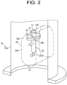
FIG. 2 is a perspective view illustrating an exhaust pipe and a through pipe in the exhaust purification apparatus according to the embodiment of the present invention. -
FIG. 3 is a front view illustrating an exhaust pipe and a through pipe in the exhaust purification apparatus according to the embodiment of the present invention. -
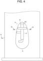
FIG. 4 is a front view illustrating an exhaust pipe and a through pipe in an exhaust purification apparatus according to an other example of the embodiment of the present invention. -
FIG. 5 is a front view illustrating an exhaust pipe and a through pipe in an exhaust purification apparatus according to an other example of the embodiment of the present invention. -
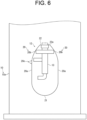
FIG. 6 is a front view illustrating an exhaust pipe and a through pipe in an exhaust purification apparatus according to an other embodiment of the present invention. - An exhaust purification apparatus 1 according to an embodiment of the present invention will be described with reference to the drawings. As illustrated in
FIG. 1 , the exhaust purification apparatus 1 is applied to anengine 100 and purifies exhaust gas discharged from theengine 100.FIG. 1 illustrates an example in which the exhaust purification apparatus 1 is applied to theengine 100 that discharges exhaust gas in a vertical direction. - The
engine 100 includes a plurality of cylinders each having a cylinder head or a cylinder block. Theengine 100 includes an intake port (not illustrated) that takes in fuel gas, and anexhaust port 101 that discharges exhaust gas in a predetermined exhaust direction (for example, upward). Anexhaust pipe 10 of the exhaust purification apparatus 1 is connected to theexhaust port 101, and theengine 100 discharges exhaust gas to theexhaust pipe 10 of the exhaust purification apparatus 1 via theexhaust port 101. - The exhaust purification apparatus 1 is constituted by a so-called selective catalytic reduction (SCR) system that purifies exhaust gas by reducing nitrogen oxides (NOx) in the exhaust gas. For example, as illustrated in
FIG. 3 , the exhaust purification apparatus 1 includes anexhaust pipe 10, a catalyst reactor 11 (catalyst), athrough pipe 12, aninjection device 13, a reducingagent supply device 14, and a coolingmedium supply device 15. - The main parts (the
exhaust pipe 10, thecatalyst reactor 11, the throughpipe 12, and the injection device 13) of the exhaust purification apparatus 1 are provided with respect to theexhaust port 101 of theengine 100, and are arranged, for example, above theexhaust port 101. The reducingagent supply device 14 and the coolingmedium supply device 15 may be provided separately from the main parts of the exhaust purification apparatus 1. The reducingagent supply device 14 and the coolingmedium supply device 15 may be integrally configured as one unit as illustrated inFIG. 1 , or may be configured as separate bodies. - The
exhaust pipe 10 allows exhaust gas discharged from theengine 100 to flow in a predetermined exhaust direction (for example, upward). Theexhaust pipe 10 is coupled to an upper side of theexhaust port 101 of theengine 100. Theexhaust pipe 10 includes astraight pipe portion 10a formed in a linear shape. - The
catalyst reactor 11 brings exhaust gas mixed with a reducing agent such as urea water into contact with a catalyst and promotes a reduction reaction in which nitrogen oxides contained in the exhaust gas are selectively reduced to nitrogen and water, thereby purifying the exhaust gas. Thecatalyst reactor 11 is provided with a catalyst such as a NOx reduction catalyst and is connected to theexhaust pipe 10 on the downstream side in the exhaust direction. Thecatalyst reactor 11 introduces exhaust gas mixed with a reducing agent injected from theinjection device 13 and flowing through theexhaust pipe 10, and brings the exhaust gas into contact with the catalyst. - The
through pipe 12 is provided in theexhaust pipe 10 on the upstream side of the catalyst reactor 11 (catalyst) in the exhaust direction in such a way as to pass through the center of theexhaust pipe 10 in the radial direction and penetrate theexhaust pipe 10 in the radial direction (direction orthogonal to the exhaust direction). Thethrough pipe 12 may be provided on astraight pipe portion 10a formed in a linear shape in theexhaust pipe 10. The throughpipe 12 is a cylindrical member of which both ends are opened, and the throughpipe 12 is provided inside theexhaust pipe 10 by connecting the both ends of the throughpipe 12 to openings provided on two opposing side surfaces of theexhaust pipe 10 by welding or the like. The exhaust gas flowing inside theexhaust pipe 10 flows on the outer peripheral surface side of thethrough pipe 12. - The
through pipe 12 has a substantially elliptical cross-sectional shape which is long in the exhaust direction, is formed in such a way that the cross-sectional shape is line-symmetrical with respect to the long axis thereof, and has the cross-sectional shape uniformly in the through direction. Thethrough pipe 12 is formed to have a streamlined side surface with no corners. - The through
pipe 12 includes a pair ofside wall portions 20 extending in the exhaust direction, anupstream side portion 21 provided over the pair ofside wall portions 20 on the upstream side in the exhaust direction, and adownstream side portion 22 provided over the pair ofside wall portions 20 on the downstream side in the exhaust direction, and has a substantially elliptical cross-sectional shape. Thethrough pipe 12 is configured in such a way such that thedownstream side portion 22 is positioned inside both ends of theupstream side portion 21 in the width direction orthogonal to the through direction and the long axis of the cross-sectional shape. - The
upstream side portion 21 of thethrough pipe 12 is formed to have, for example, a semicircular or semielliptical arc-shaped cross section which is convex toward the upstream side in the exhaust direction, and causes the exhaust gas flowing from the upstream side to flow to the outer peripheral surface side of the pair ofside wall portions 20. - The pair of
side wall portions 20 of thethrough pipe 12 is formed to be curved in a streamlined shape in such a way that a width of the cross-sectional shape decreases toward the downstream side in the exhaust direction. For example, the pair ofside wall portions 20 is formed to be curved with a curvature smaller than that of theupstream side portion 21. For example, theside wall portion 20 is formed to have alinear portion 20a extending continuously from an end part of theupstream side portion 21 in the exhaust direction and acurved portion 20b curved continuously from a downstream end part of thelinear portion 20a to the center side in the width direction of the cross-sectional shape. Theside wall portion 20 causes the exhaust gas flowing from the upstream side to flow along the outer peripheral surface, and creates a flow toward the center side in the width direction of the cross-sectional shape toward the downstream side. - The
downstream side portion 22 of the throughpipe 12 has aplanar portion 22a orthogonal to the exhaust direction and is formed continuously from downstream end parts of the pair ofside wall portions 20. - The
through pipe 12 is formed by, for example, joining members having the same shape by welding or the like, and by providing a welding position in theupstream side portion 21 or thedownstream side portion 22, it is possible to form a side surface having a streamlined shape with no corners, without providing a weld overlay portion on the side surface. - With the above-described configuration of the
through pipe 12, the exhaust gas flowing on the outer peripheral surface side of the throughpipe 12 is branched to both sides in the width direction by theupstream side portion 21, then flows toward the center side in the width direction without stagnation along the pair ofside wall portions 20 having a streamlined shape toward the center side in the width direction, and merges on the downstream side of thedownstream side portion 22 without forming a dead water region such as a vortex retention region. In other words, thethrough pipe 12 is formed to have the pair ofside wall portions 20 having a streamlined shape in such a way as not to form a dead water region on the downstream side of thedownstream side portion 22. - The
injection device 13 is provided inside thethrough pipe 12 with only the tip having an ejection hole exposed to the inside of theexhaust pipe 10. For example, theinjection device 13 is constituted by an injection nozzle, an injection valve, or the like. Theinjection device 13 is connected to the reducingagent supply device 14 and injects a reducing agent such as urea water for reducing exhaust gas supplied from the reducingagent supply device 14 into theexhaust pipe 10. Note that theinjection device 13 may be arranged in such a way as to inject the reducing agent to a position where the exhaust gases merge on the downstream side of thedownstream side portion 22 of the throughpipe 12. - The reducing
agent supply device 14 is connected to a control device (not illustrated), and injects the reducing agent through theinjection device 13 in response to an instruction signal from the control device. Theinjection device 13 is cooled by a cooling medium such as air flowing inside the throughpipe 12. - The
injection device 13 is provided on the downstream side in the exhaust direction between the pair ofside wall portions 20 inside the throughpipe 12. For example, theinjection device 13 is provided on adownstream side portion 22 of the throughpipe 12, to be specific, on aplanar portion 22a of the throughpipe 12. Theinjection device 13 is provided in such a way as to inject the reducing agent toward the downstream side in the exhaust direction, for example, toward the catalyst reactor 11 (catalyst) arranged on the downstream side. For example, oneinjection device 13 may be provided at the center in the through direction of the throughpipe 12, or a plurality ofinjection devices 13 may be provided at intervals in the through direction of the throughpipe 12. In the present embodiment, since theinjection device 13 is arranged in thestraight pipe portion 10a of theexhaust pipe 10 and thecatalyst reactor 11 is arranged at a downstream end of thestraight pipe portion 10a, theinjection device 13 is configured to inject the reducing agent toward thecatalyst reactor 11, but the present invention is not limited to this embodiment. Alternatively, in an other example, thecatalyst reactor 11 may be arranged in a bent pipe of theexhaust pipe 10 instead of thestraight pipe portion 10a. To be specific, a bent pipe may be connected to the downstream end of thestraight pipe portion 10a, and thecatalyst reactor 11 may be connected to a downstream end of the bent pipe. In this case, theinjection device 13 may be arranged in thestraight pipe portion 10a, or may be arranged in the bent pipe. Namely, the reducing agent may be injected toward the downstream side of the inside of theexhaust pipe 10 in the exhaust direction. - The reducing
agent supply device 14 is connected to theinjection device 13 via a reducingagent supply pipe 16, sucks up the reducing agent stored in a reducingagent tank 17 by using a pump or the like, and supplies the reducing agent to theinjection device 13 via the reducingagent supply pipe 16. - The cooling
medium supply device 15 is connected to theinjection device 13 via a coolingmedium supply pipe 18, and supplies a cooling medium such as air supplied from anair supply section 19 to theinjection device 13 via the coolingmedium supply pipe 18. For example, the coolingmedium supply device 15 may introduce air cooled by an intercooler (not illustrated) and supply the air as a cooling medium. Alternatively, the coolingmedium supply device 15 may supply cooling water as the cooling medium instead of air. - As described above, according to the present invention, the exhaust purification apparatus 1 for purifying nitrogen oxides in exhaust gas includes the
exhaust pipe 10 that causes exhaust gas discharged from theengine 100 to flow in a predetermined exhaust direction, the catalyst reactor 11 (catalyst) provided in theexhaust pipe 10 and reduces the nitrogen oxides in the exhaust gas, the throughpipe 12 provided on the upstream side of thecatalyst reactor 11 in the exhaust direction, in such a way as to penetrate theexhaust pipe 10 in a direction orthogonal to the exhaust direction, and theinjection device 13 provided inside the throughpipe 12 and injects a reducing agent for reducing exhaust gas into theexhaust pipe 10. - Thus, according to the exhaust purification apparatus 1 of the present invention, the
injection device 13 that injects the reducing agent at the center position of theexhaust pipe 10 can be easily arranged and maintained by using the throughpipe 12. Further, by using the throughpipe 12, the reducing agent can be injected at the center position of theexhaust pipe 10 without inserting most of theinjection device 13 into theexhaust pipe 10. Furthermore, by using the throughpipe 12 with both ends penetrated, air permeability inside the throughpipe 12 is improved, an influence of radiant heat from the wall surface of the throughpipe 12 is suppressed, the inside of the throughpipe 12 is suppressed from becoming a heat reservoir, cooling performance at the position of theinjection device 13 can be improved, and thermal damage to theinjection device 13 can be suppressed. - Further, in the exhaust purification apparatus 1 of the present invention, the
injection device 13 is provided inside the throughpipe 12 on the downstream side in the exhaust direction in such a way as to inject the reducing agent toward thecatalyst reactor 11. - Thus, since the reducing agent can be injected into the exhaust gas flowing toward the
catalyst reactor 11, stirring efficiency of the reducing agent can be improved, and generation of deposits can be suppressed. - Further, in the exhaust purification apparatus 1 of the present invention, the through
pipe 12 has theplanar portion 22a orthogonal to the exhaust direction on the downstream side in the exhaust direction, and theinjection device 13 is provided on theplanar portion 22a of the throughpipe 12. - As a result, accuracy of the injection direction of the
injection device 13 can be improved, the stirring efficiency of the reducing agent can be improved, and generation of deposits can be suppressed. - Further, in the exhaust purification apparatus 1 of the present invention, the through
pipe 12 is provided in thestraight pipe portion 10a formed in a linear shape in theexhaust pipe 10. - Thus, the reducing agent can be injected into the exhaust gas traveling straight toward the
catalyst reactor 11, and therefore, the reducing agent can be prevented from adhering to theexhaust pipe 10 and the throughpipe 12. - Further, in the exhaust purification apparatus 1 of the present invention, the through
pipe 12 has the pair ofside wall portions 20 extending in the exhaust direction and has a substantially elliptical cross-sectional shape elongated in the exhaust direction, and the pair ofside wall portions 20 are formed to be curved in a streamlined shape, in such a way that the width of the cross-sectional shape decreases toward the downstream side in the exhaust direction. - Thus, the exhaust gas flowing on the outer peripheral surface side of the pair of
side wall portions 20 can be suppressed from being separated from the pair ofside wall portions 20, the exhaust gas can be caused to flow toward the center side in the width direction along the pair ofside wall portions 20 without stagnation, and the exhaust gas can be caused to merge on the downstream side without forming a dead water region such as a vortex retention region. Therefore, regardless of penetration force of theinjection device 13, the reducing agent injected from theinjection device 13 can be efficiently mixed with the exhaust gas and supplied to thecatalyst reactor 11. - In addition, in the exhaust purification apparatus 1 of the present invention, the through
pipe 12 has theupstream side portion 21 having an arc-shaped cross section on the upstream side of the pair ofside wall portions 20 in the exhaust direction, and the pair ofside wall portions 20 is formed to be curved with a curvature smaller than that of theupstream side portion 21. - Thus, it is possible to improve the performance of causing the exhaust gas to flow toward the center side in the width direction along the pair of
side wall portions 20 without stagnation. - Further, in the exhaust purification apparatus 1 of the present invention, the through
pipe 12 is formed in such a way that the cross-sectional shape thereof is line symmetrical with respect to the central axis extending in the exhaust direction. - Thus, the flow of the exhaust gas on the outer peripheral surface side of the through
pipe 12 can be made symmetrical inside theexhaust pipe 10, and the injected reducing agent can be prevented from flowing to the inner wall surface side of theexhaust pipe 10. - In the above-described embodiment, the example in which the pair of
side wall portions 20 constituting the streamlined shape of the side surface of the throughpipe 12 has thelinear portion 20a extending in the exhaust direction continuously from the end part of theupstream side portion 21 has been described, but the present invention is not limited to this example. In an other example, as illustrated inFIG. 4 , the pair ofside wall portions 20 may have acurved portion 20b constituting a streamlined shape, which is formed continuously from the end part of theupstream side portion 21, without having alinear portion 20a. - Further, in the above-described embodiment, the example in which the through
pipe 12 has thedownstream side portion 22 including theplanar portion 22a orthogonal to the exhaust direction has been described, but the present invention is not limited to this example. In an other example, as illustrated inFIG. 5 , the throughpipe 12 may have a pair ofcurved portions 20b joined at the center in the width direction, without having thedownstream side portion 22. In this case, theinjection device 13 may be provided at a joint between the pair ofcurved portions 20b. - Further, in an other embodiment, as illustrated in
FIG. 6 , the throughpipe 12 may include aprotrusion 20c protruding outward in the width direction on at least one of the pair ofside wall portions 20. Theprotrusion 20c acts as a vortex generator outside theside wall portion 20, and after the exhaust gas is separated from theside wall portion 20 by theprotrusion 20c, the protrusion generates a vortex flow toward the downstream side in the exhaust direction and toward the center side in the width direction. Theprotrusion 20c is provided, for example, in a transition portion where theside wall portion 20 transitions from thelinear portion 20a to thecurved portion 20b. In this case, theside wall portion 20 provided with theprotrusion 20c may not have a streamlined shape. Oneprotrusion 20c may be provided at the center in the through direction, or a plurality ofprotrusions 20c may be provided at intervals in the through direction. - According to such an other embodiment, by generating a vortex acting on the exhaust gas flowing on the outer peripheral surface side of the
side wall portion 20, the exhaust gas can be suppressed from being separated from theside wall portion 20, the exhaust gas can be caused to flow toward the center side in the width direction on the downstream side of the throughpipe 12, and the exhaust gas can be caused to merge on the downstream side without forming a dead water region such as a vortex retention region. Therefore, regardless of penetration force of theinjection device 13, the reducing agent injected from theinjection device 13 can be efficiently mixed with the exhaust gas and supplied to thecatalyst reactor 11. - Note that the present invention can be properly modified within a range which does not contradict to a gist or a concept of the present invention that can be read throughout the claims and the specification, and an exhaust purification apparatus involving such modifications is also included in the technical concept of the present invention.
- Hereinafter, the summary of the invention extracted from the above-described embodiments will be supplementarily noted. Configurations and processing functions to be described in the following supplementary notes may be selected and combined as appropriate.
- An exhaust purification apparatus that purifies nitrogen oxides in exhaust gas, the exhaust purification apparatus including:
- an exhaust pipe that causes the exhaust gas discharged from an engine to flow;
- a catalyst that is provided in the exhaust pipe and that reduces the nitrogen oxides in the exhaust gas;
- a through pipe that is provided in such a way as to penetrate the exhaust pipe; and
- an injection device that is provided inside the through pipe and that injects a reducing agent that reduces the exhaust gas into the exhaust pipe.
- The exhaust purification apparatus according to supplementary note 1, wherein the injection device is provided in such a way as to inject the reducing agent to a downstream side in the exhaust direction.
- The exhaust purification apparatus according to supplementary note 1 or 2, wherein
- the through pipe has a planar portion on a downstream side in the exhaust direction, and
- the injection device is provided on the planar portion.
- The exhaust purification apparatus according to any one of supplementary notes 1 to 3, wherein the through pipe is provided in a straight pipe portion formed in a linear shape in the exhaust pipe.
- The exhaust purification apparatus according to any one of supplementary notes 1 to 4, wherein
- the through pipe includes a pair of side wall portions extending in the exhaust direction and has a substantially elliptical cross-sectional shape elongated in the exhaust direction, and
- the pair of side wall portions are formed in such a way that a width of the cross-sectional shape decreases toward a downstream side in the exhaust direction.
- The exhaust purification apparatus according to supplementary note 5, wherein
- the through pipe includes an upstream side portion having an arc-shaped cross section on an upstream side of the pair of side wall portions, and
- the pair of side wall portions are formed to be curved with a curvature smaller than that of the upstream side portion.
- The exhaust purification apparatus according to any one of supplementary notes 1 to 6, wherein the through pipe is formed in such a way that a cross-sectional shape thereof is line-symmetric with respect to a central axis extending in an exhaust direction.
-
- 1 exhaust purification apparatus
- 10 exhaust pipe
- 10a straight pipe portion
- 11 catalyst reactor (catalyst)
- 12 through pipe
- 13 injection device
- 14 reducing agent supply device
- 15 cooling medium supply device
- 16 reducing agent supply pipe
- 17 reducing agent tank
- 18 cooling medium supply pipe
- 19 air supply section
- 20 side wall portion
- 20a linear portion
- 20b curved portion
- 20c protrusion
- 21 upstream side portion
- 22 downstream side portion
- 100 engine
- 101 exhaust port
Claims (7)
- An exhaust purification apparatus that purifies nitrogen oxides in exhaust gas, the exhaust purification apparatus comprising:an exhaust pipe that causes the exhaust gas discharged from an engine to flow;a catalyst that is provided in the exhaust pipe and that reduces the nitrogen oxides in the exhaust gas;a through pipe that is provided in such a way as to penetrate the exhaust pipe; andan injection device that is provided inside the through pipe and that injects a reducing agent that reduces the exhaust gas into the exhaust pipe.
- The exhaust purification apparatus according to claim 1, wherein the injection device is provided in such a way as to inject the reducing agent to a downstream side in an exhaust direction.
- The exhaust purification apparatus according to claim 1, whereinthe through pipe has a planar portion on a downstream side in an exhaust direction, andthe injection device is provided on the planar portion.
- The exhaust purification apparatus according to claim 1, wherein the through pipe is provided in a straight pipe portion formed in a linear shape in the exhaust pipe.
- The exhaust purification apparatus according to claim 1, whereinthe through pipe has a pair of side wall portions extending in an exhaust direction, and has a substantially elliptical cross-sectional shape elongated in the exhaust direction, andthe pair of side wall portions are formed in such a way that a width of the cross-sectional shape decreases toward a downstream side in the exhaust direction.
- The exhaust purification apparatus according to claim 5, whereinthe through pipe has an upstream side portion having an arc-shaped cross section on an upstream side of the pair of side wall portions, andthe pair of side wall portions are formed to be curved with a curvature smaller than that of the upstream side portion.
- The exhaust purification apparatus according to claim 1, wherein the through pipe is formed in such a way that a cross-sectional shape thereof is line-symmetrical with respect to a central axis extending in an exhaust direction.
Applications Claiming Priority (1)
| Application Number | Priority Date | Filing Date | Title |
|---|---|---|---|
| JP2023195630A JP2025082365A (en) | 2023-11-17 | 2023-11-17 | Exhaust emission control device |
Publications (1)
| Publication Number | Publication Date |
|---|---|
| EP4556693A1 true EP4556693A1 (en) | 2025-05-21 |
Family
ID=93430584
Family Applications (1)
| Application Number | Title | Priority Date | Filing Date |
|---|---|---|---|
| EP24210786.0A Pending EP4556693A1 (en) | 2023-11-17 | 2024-11-05 | Exhaust purification apparatus |
Country Status (5)
| Country | Link |
|---|---|
| US (1) | US12398664B2 (en) |
| EP (1) | EP4556693A1 (en) |
| JP (1) | JP2025082365A (en) |
| KR (1) | KR20250072864A (en) |
| CN (1) | CN120020366A (en) |
Citations (8)
| Publication number | Priority date | Publication date | Assignee | Title |
|---|---|---|---|---|
| WO2012008572A1 (en) * | 2010-07-16 | 2012-01-19 | いすゞ自動車株式会社 | Exhaust gas purification device |
| JP4861974B2 (en) * | 2007-12-21 | 2012-01-25 | 三菱ふそうトラック・バス株式会社 | Engine exhaust purification system |
| JP2014234793A (en) | 2013-06-04 | 2014-12-15 | ヤンマー株式会社 | Urea water injection nozzle |
| US10030560B2 (en) * | 2013-12-18 | 2018-07-24 | Hino Motors, Ltd. | Exhaust purification device |
| EP2549069B1 (en) * | 2010-03-19 | 2019-04-10 | Hino Motors, Ltd. | Exhaust gas purification device |
| US11268424B2 (en) * | 2018-05-16 | 2022-03-08 | Nissin Kogyo Co., Ltd. | Exhaust gas purification device |
| US20220090530A1 (en) * | 2019-01-17 | 2022-03-24 | Hjs Emission Technology Gmbh & Co. Kg | Device To Convey A Checmical Reactant Into The Exhaust Gas Stream Of A Combustion Engine |
| WO2023041843A1 (en) * | 2021-09-16 | 2023-03-23 | Proventia Oy | Flow device |
Family Cites Families (17)
| Publication number | Priority date | Publication date | Assignee | Title |
|---|---|---|---|---|
| US3209531A (en) * | 1962-05-18 | 1965-10-05 | Morris | Adaptable afterburner |
| US5992141A (en) * | 1996-04-02 | 1999-11-30 | Kleen Air Systems, Inc. | Ammonia injection in NOx control |
| US6799423B2 (en) * | 2002-01-24 | 2004-10-05 | David L. Piekarski | Adjustable exhaust system for internal combustion engine |
| JP2005105970A (en) * | 2003-09-30 | 2005-04-21 | Nissan Diesel Motor Co Ltd | Exhaust emission control device of engine |
| US7748212B2 (en) * | 2007-03-09 | 2010-07-06 | Cummins Filtration Ip, Inc. | Exhaust aftertreatment system with flow distribution |
| JP5173308B2 (en) * | 2007-07-31 | 2013-04-03 | 日野自動車株式会社 | Exhaust purification device |
| US7740008B2 (en) * | 2007-10-23 | 2010-06-22 | International Engine Intellectual Property Company, Llc | Multiple height fluid mixer and method of use |
| US8646258B2 (en) * | 2009-06-18 | 2014-02-11 | Renault Trucks | Mixing system in an exhaust gas mixing chamber |
| US20130213013A1 (en) * | 2011-01-14 | 2013-08-22 | Cummins Ip, Inc. | Exhaust gas sensor module |
| JP6053096B2 (en) * | 2012-01-12 | 2016-12-27 | 日野自動車株式会社 | Exhaust purification device |
| JP6185366B2 (en) * | 2013-10-31 | 2017-08-23 | 日野自動車株式会社 | Exhaust purification device |
| US9482132B2 (en) * | 2013-11-07 | 2016-11-01 | Cummins Emission Solutions, Inc. | Gaseous reductant delivery devices and systems |
| CN204552896U (en) * | 2014-12-26 | 2015-08-12 | 康明斯排放处理公司 | Only carry center line injecting systems and the after-treatment system of liquid reducer |
| US9932875B2 (en) * | 2016-03-02 | 2018-04-03 | Ford Global Technologies, Llc | Mixer for mixing exhaust gas |
| US10161362B2 (en) * | 2016-08-29 | 2018-12-25 | Ford Global Technologies, Llc | Systems and methods for an exhaust gas recirculation mixer |
| US10273854B1 (en) * | 2017-12-20 | 2019-04-30 | Cnh Industrial America Llc | Exhaust system for a work vehicle |
| US11691120B1 (en) * | 2021-12-20 | 2023-07-04 | Cummins Emission Solutions Inc. | Exhaust gas aftertreatment systems |
-
2023
- 2023-11-17 JP JP2023195630A patent/JP2025082365A/en active Pending
-
2024
- 2024-10-28 KR KR1020240148542A patent/KR20250072864A/en active Pending
- 2024-10-29 US US18/929,734 patent/US12398664B2/en active Active
- 2024-11-05 EP EP24210786.0A patent/EP4556693A1/en active Pending
- 2024-11-15 CN CN202411632108.2A patent/CN120020366A/en active Pending
Patent Citations (8)
| Publication number | Priority date | Publication date | Assignee | Title |
|---|---|---|---|---|
| JP4861974B2 (en) * | 2007-12-21 | 2012-01-25 | 三菱ふそうトラック・バス株式会社 | Engine exhaust purification system |
| EP2549069B1 (en) * | 2010-03-19 | 2019-04-10 | Hino Motors, Ltd. | Exhaust gas purification device |
| WO2012008572A1 (en) * | 2010-07-16 | 2012-01-19 | いすゞ自動車株式会社 | Exhaust gas purification device |
| JP2014234793A (en) | 2013-06-04 | 2014-12-15 | ヤンマー株式会社 | Urea water injection nozzle |
| US10030560B2 (en) * | 2013-12-18 | 2018-07-24 | Hino Motors, Ltd. | Exhaust purification device |
| US11268424B2 (en) * | 2018-05-16 | 2022-03-08 | Nissin Kogyo Co., Ltd. | Exhaust gas purification device |
| US20220090530A1 (en) * | 2019-01-17 | 2022-03-24 | Hjs Emission Technology Gmbh & Co. Kg | Device To Convey A Checmical Reactant Into The Exhaust Gas Stream Of A Combustion Engine |
| WO2023041843A1 (en) * | 2021-09-16 | 2023-03-23 | Proventia Oy | Flow device |
Also Published As
| Publication number | Publication date |
|---|---|
| JP2025082365A (en) | 2025-05-29 |
| KR20250072864A (en) | 2025-05-26 |
| CN120020366A (en) | 2025-05-20 |
| US12398664B2 (en) | 2025-08-26 |
| US20250163838A1 (en) | 2025-05-22 |
Similar Documents
| Publication | Publication Date | Title |
|---|---|---|
| EP4256183B1 (en) | Exhaust pipe | |
| US9217348B2 (en) | Exhaust gas purification device | |
| CN103210192B (en) | Exhaust stream vortex-proof device | |
| US9644516B1 (en) | Mounting plate for mounting injectors and directing reductant flow in exhaust conduits | |
| EP3030767B1 (en) | Method, apparatus and system for aftertreatment of exhaust gas | |
| EP3364005A1 (en) | Exhaust gas purification device for ship | |
| EP3313558B1 (en) | Method, apparatus and mixing device for evenly mixing reactant to exhaust gas flow | |
| CN103119261A (en) | Inverted exhaust gas treatment injector | |
| KR101983520B1 (en) | Exhaust gas purifier of ship | |
| US10030560B2 (en) | Exhaust purification device | |
| CN104564262A (en) | System and apparatus for reducing reductant deposit formation in exhaust aftertreatment systems | |
| EP3327263A1 (en) | Apparatus for aftertreatment of exhaust gas comprising inline housing | |
| US12398664B2 (en) | Exhaust purification apparatus | |
| US20090100827A1 (en) | Exhaust gas purification apparatus for internal combustion engine | |
| EP2573349A1 (en) | Exhaust pipe | |
| EP3489480B1 (en) | Scr mixer and scr device comprising same | |
| EP2180156A1 (en) | Injection system for injecting a reducing substance into an exhaust system of an internal combustion engine | |
| KR102012609B1 (en) | Exhaust filter | |
| JP2019157826A (en) | Exhaust emission control device of internal combustion engine and pipe member applied to the device | |
| CN115315572A (en) | mixer | |
| US11247173B1 (en) | Two-stage mixer | |
| CN115210456B (en) | Exhaust structure | |
| CN114076018B (en) | Two-stage mixer | |
| KR20250059677A (en) | Urea supply module | |
| CN112096489A (en) | Exhaust gas system for exhaust gas aftertreatment |
Legal Events
| Date | Code | Title | Description |
|---|---|---|---|
| PUAI | Public reference made under article 153(3) epc to a published international application that has entered the european phase |
Free format text: ORIGINAL CODE: 0009012 |
|
| STAA | Information on the status of an ep patent application or granted ep patent |
Free format text: STATUS: THE APPLICATION HAS BEEN PUBLISHED |
|
| AK | Designated contracting states |
Kind code of ref document: A1 Designated state(s): AL AT BE BG CH CY CZ DE DK EE ES FI FR GB GR HR HU IE IS IT LI LT LU LV MC ME MK MT NL NO PL PT RO RS SE SI SK SM TR |
|
| STAA | Information on the status of an ep patent application or granted ep patent |
Free format text: STATUS: REQUEST FOR EXAMINATION WAS MADE |
|
| STAA | Information on the status of an ep patent application or granted ep patent |
Free format text: STATUS: EXAMINATION IS IN PROGRESS |
|
| 17P | Request for examination filed |
Effective date: 20251120 |
|
| 17Q | First examination report despatched |
Effective date: 20251205 |