EP4556685A1 - Multi-material abradable shroud for gas turbine engine rotor - Google Patents
Multi-material abradable shroud for gas turbine engine rotor Download PDFInfo
- Publication number
- EP4556685A1 EP4556685A1 EP24213111.8A EP24213111A EP4556685A1 EP 4556685 A1 EP4556685 A1 EP 4556685A1 EP 24213111 A EP24213111 A EP 24213111A EP 4556685 A1 EP4556685 A1 EP 4556685A1
- Authority
- EP
- European Patent Office
- Prior art keywords
- protrusions
- protrusion
- base
- shroud
- abradable
- Prior art date
- Legal status (The legal status is an assumption and is not a legal conclusion. Google has not performed a legal analysis and makes no representation as to the accuracy of the status listed.)
- Pending
Links
Images



Classifications
-
- F—MECHANICAL ENGINEERING; LIGHTING; HEATING; WEAPONS; BLASTING
- F01—MACHINES OR ENGINES IN GENERAL; ENGINE PLANTS IN GENERAL; STEAM ENGINES
- F01D—NON-POSITIVE DISPLACEMENT MACHINES OR ENGINES, e.g. STEAM TURBINES
- F01D11/00—Preventing or minimising internal leakage of working-fluid, e.g. between stages
- F01D11/08—Preventing or minimising internal leakage of working-fluid, e.g. between stages for sealing space between rotor blade tips and stator
- F01D11/12—Preventing or minimising internal leakage of working-fluid, e.g. between stages for sealing space between rotor blade tips and stator using a rubstrip, e.g. erodible. deformable or resiliently-biased part
- F01D11/122—Preventing or minimising internal leakage of working-fluid, e.g. between stages for sealing space between rotor blade tips and stator using a rubstrip, e.g. erodible. deformable or resiliently-biased part with erodable or abradable material
-
- F—MECHANICAL ENGINEERING; LIGHTING; HEATING; WEAPONS; BLASTING
- F02—COMBUSTION ENGINES; HOT-GAS OR COMBUSTION-PRODUCT ENGINE PLANTS
- F02C—GAS-TURBINE PLANTS; AIR INTAKES FOR JET-PROPULSION PLANTS; CONTROLLING FUEL SUPPLY IN AIR-BREATHING JET-PROPULSION PLANTS
- F02C7/00—Features, components parts, details or accessories, not provided for in, or of interest apart form groups F02C1/00 - F02C6/00; Air intakes for jet-propulsion plants
- F02C7/24—Heat or noise insulation
-
- F—MECHANICAL ENGINEERING; LIGHTING; HEATING; WEAPONS; BLASTING
- F01—MACHINES OR ENGINES IN GENERAL; ENGINE PLANTS IN GENERAL; STEAM ENGINES
- F01D—NON-POSITIVE DISPLACEMENT MACHINES OR ENGINES, e.g. STEAM TURBINES
- F01D11/00—Preventing or minimising internal leakage of working-fluid, e.g. between stages
- F01D11/08—Preventing or minimising internal leakage of working-fluid, e.g. between stages for sealing space between rotor blade tips and stator
- F01D11/12—Preventing or minimising internal leakage of working-fluid, e.g. between stages for sealing space between rotor blade tips and stator using a rubstrip, e.g. erodible. deformable or resiliently-biased part
- F01D11/122—Preventing or minimising internal leakage of working-fluid, e.g. between stages for sealing space between rotor blade tips and stator using a rubstrip, e.g. erodible. deformable or resiliently-biased part with erodable or abradable material
- F01D11/125—Preventing or minimising internal leakage of working-fluid, e.g. between stages for sealing space between rotor blade tips and stator using a rubstrip, e.g. erodible. deformable or resiliently-biased part with erodable or abradable material with a reinforcing structure
-
- F—MECHANICAL ENGINEERING; LIGHTING; HEATING; WEAPONS; BLASTING
- F01—MACHINES OR ENGINES IN GENERAL; ENGINE PLANTS IN GENERAL; STEAM ENGINES
- F01D—NON-POSITIVE DISPLACEMENT MACHINES OR ENGINES, e.g. STEAM TURBINES
- F01D11/00—Preventing or minimising internal leakage of working-fluid, e.g. between stages
- F01D11/08—Preventing or minimising internal leakage of working-fluid, e.g. between stages for sealing space between rotor blade tips and stator
- F01D11/12—Preventing or minimising internal leakage of working-fluid, e.g. between stages for sealing space between rotor blade tips and stator using a rubstrip, e.g. erodible. deformable or resiliently-biased part
- F01D11/127—Preventing or minimising internal leakage of working-fluid, e.g. between stages for sealing space between rotor blade tips and stator using a rubstrip, e.g. erodible. deformable or resiliently-biased part with a deformable or crushable structure, e.g. honeycomb
-
- F—MECHANICAL ENGINEERING; LIGHTING; HEATING; WEAPONS; BLASTING
- F01—MACHINES OR ENGINES IN GENERAL; ENGINE PLANTS IN GENERAL; STEAM ENGINES
- F01D—NON-POSITIVE DISPLACEMENT MACHINES OR ENGINES, e.g. STEAM TURBINES
- F01D5/00—Blades; Blade-carrying members; Heating, heat-insulating, cooling or antivibration means on the blades or the members
- F01D5/12—Blades
- F01D5/14—Form or construction
-
- F—MECHANICAL ENGINEERING; LIGHTING; HEATING; WEAPONS; BLASTING
- F05—INDEXING SCHEMES RELATING TO ENGINES OR PUMPS IN VARIOUS SUBCLASSES OF CLASSES F01-F04
- F05D—INDEXING SCHEME FOR ASPECTS RELATING TO NON-POSITIVE-DISPLACEMENT MACHINES OR ENGINES, GAS-TURBINES OR JET-PROPULSION PLANTS
- F05D2230/00—Manufacture
- F05D2230/90—Coating; Surface treatment
-
- F—MECHANICAL ENGINEERING; LIGHTING; HEATING; WEAPONS; BLASTING
- F05—INDEXING SCHEMES RELATING TO ENGINES OR PUMPS IN VARIOUS SUBCLASSES OF CLASSES F01-F04
- F05D—INDEXING SCHEME FOR ASPECTS RELATING TO NON-POSITIVE-DISPLACEMENT MACHINES OR ENGINES, GAS-TURBINES OR JET-PROPULSION PLANTS
- F05D2240/00—Components
- F05D2240/10—Stators
- F05D2240/11—Shroud seal segments
-
- F—MECHANICAL ENGINEERING; LIGHTING; HEATING; WEAPONS; BLASTING
- F05—INDEXING SCHEMES RELATING TO ENGINES OR PUMPS IN VARIOUS SUBCLASSES OF CLASSES F01-F04
- F05D—INDEXING SCHEME FOR ASPECTS RELATING TO NON-POSITIVE-DISPLACEMENT MACHINES OR ENGINES, GAS-TURBINES OR JET-PROPULSION PLANTS
- F05D2300/00—Materials; Properties thereof
- F05D2300/40—Organic materials
- F05D2300/43—Synthetic polymers, e.g. plastics; Rubber
Definitions
- This disclosure relates generally to a gas turbine engine and, more particularly, to an abradable shroud for the gas turbine engine.
- a gas turbine engine may include an abradable shroud housing a bladed rotor.
- abradable shrouds Various types and configurations of abradable shrouds are known in the art. While these known abradable shrouds have various benefits, there is still room in the art for improvement.
- an apparatus for a gas turbine engine.
- This apparatus includes a shroud, and the shroud includes a base and an abradable coating system.
- the base extends axially along and circumferentially about an axis.
- the base extends radially between a base inner side and a base outer side.
- the abradable coating system is bonded to and covers the base at the base inner side.
- the abradable coating system includes a plurality of protrusions and an elastomeric material.
- the protrusions are arranged circumferentially about the axis in a circumferentially extending array. Each of the protrusions projects in a radial inward direction away from the base inner side to a distal inner end.
- Each of the protrusions is configured from or otherwise includes an abradable material.
- the elastomeric material fills a gap between each circumferentially neighboring pair of the protrusions.
- this apparatus includes a shroud, and the shroud includes a base and an abradable coating system.
- the base extends axially along and circumferentially about an axis.
- the abradable coating system is connected to the base along a radial inner side of the base.
- the abradable coating system includes a plurality of upstream protrusions, a plurality of downstream protrusions and an elastomeric material.
- the upstream protrusions are arranged circumferentially about the axis in an upstream array. Each of the upstream protrusions project radial inward away from the base inner side.
- Each of the upstream protrusions is configured from or otherwise includes an abradable material.
- the downstream protrusions are arranged circumferentially about the axis in a downstream array.
- Each of the downstream protrusions projects radial inward away from the base inner side.
- Each of the downstream protrusions is configured from or otherwise includes the abradable material.
- the elastomeric material extends circumferentially about the axis and axially between the upstream array and the downstream array.
- this apparatus includes a shroud, and the shroud includes a base and an abradable coating system.
- the base extends axially along and circumferentially about an axis.
- the abradable coating system is connected to the base along a radial inner side of the base.
- the abradable coating system includes a plurality of protrusions and a polymeric material extending around an exterior perimeter of each of the protrusions.
- the protrusions are arranged circumferentially about the axis in a circumferentially extending array.
- Each of the protrusions projects in a radial inward direction away from the base inner side to a distal inner end.
- Each of the protrusions is configured from or otherwise includes an abradable material.
- the elastomeric material may surround each of the upstream protrusions. In addition or alternatively, the elastomeric material may surround each of the downstream protrusions.
- the protrusions may include a first protrusion.
- the elastomeric material may surround the first protrusion.
- the protrusions may include a first protrusion.
- the shroud may extend radially between a shroud inner side and a shroud outer side.
- the shroud inner side may be collectively formed by the distal inner end of the first protrusion and the elastomeric material.
- the protrusions may include a first protrusion and a second protrusion.
- the elastomeric material may extend laterally between and may be bonded to the first protrusion and the second protrusion.
- the protrusions may include a first protrusion.
- the first protrusion may project radially from the base inner side to the distal inner end of the first protrusion.
- the elastomeric material may project radially to the base inner side along the first protrusion.
- the protrusions may include a first protrusion.
- the first protrusion may be configured as a pedestal.
- the protrusions may include a first protrusion.
- the first protrusion may be configured as a rib.
- the protrusions may include a first protrusion.
- the first protrusion may project along a span line in the radial inward direction away from the base inner side to the distal inner end of the first protrusion.
- the span line may be perpendicular to the base first side.
- the protrusions may include a first protrusion.
- the first protrusion may project along a span line in the radial inward direction away from the base inner side to the distal inner end of the first protrusion.
- the span line may be angularly offset from the base first side by an included acute angle.
- the protrusions may include a first protrusion.
- the first protrusion may have a lateral protrusion width.
- the lateral protrusion width may be uniform as at least a portion of the first protrusion projects radially in the radial inward direction away from the base inner side.
- the protrusions may include a first protrusion.
- the first protrusion may have a lateral protrusion width.
- the lateral protrusion width may change as at least a portion of the first protrusion projects radially in the radial inward direction away from the base inner side.
- the protrusions may include a first protrusion.
- the first protrusion may have a circular cross-sectional geometry.
- the protrusions may include a first protrusion.
- the first protrusion may have an elongated cross-sectional geometry.
- the protrusions may include a first protrusion.
- the first protrusion may have a polygonal cross-sectional geometry.
- the protrusions may be a plurality of first protrusions.
- the abradable coating system may also include a plurality of second protrusions.
- the second protrusions may be arranged circumferentially about the axis in a second circumferentially extending array.
- Each of the second protrusions may project in the radial inward direction away from the base inner side to a second distal inner end.
- Each of the second protrusions may be configured from or otherwise include the abradable material.
- the elastomeric material may fill a second gap between each axially neighboring pair of one of the first protrusions and one of the second protrusions.
- the apparatus may also include a bladed rotor rotatable about the axis.
- the bladed rotor may include a rotor base and a plurality of rotor blades arranged circumferentially around rotor base.
- the abradable coating system may form an outer peripheral boundary of a flowpath.
- Each of the rotor blades may project radially out from the rotor base into the flowpath towards the abradable coating system.
- the present disclosure may include any one or more of the individual features disclosed above and/or below alone or in any combination thereof.
- FIG. 1 schematically illustrates a rotor section 20 of a gas turbine engine powerplant for an aircraft.
- the aircraft may be an airplane, a helicopter, a drone (e.g., an unmanned aerial vehicle (UAV)) or any other manned or unmanned aerial vehicle or system.
- the powerplant may be configured as, or otherwise included as part of, a propulsion system for the aircraft.
- the powerplant for example, may be a turbofan gas turbine engine, a turbojet gas turbine engine, a turboprop gas turbine engine or a turboshaft gas turbine engine.
- the powerplant may also or alternatively be configured as, or otherwise included as part of, an electrical power system for the aircraft.
- the powerplant for example, may be an auxiliary power unit (APU) for the aircraft.
- APU auxiliary power unit
- the present disclosure is not limited to such exemplary powerplants nor to aircraft applications.
- the powerplant for example, may alternatively be an industrial gas turbine engine.
- the rotor section 20 may be configured as, or otherwise included as part of, a compressor section of the powerplant; e.g., a low pressure compressor (LPC) section.
- the rotor section 20 may alternatively be configured as, or otherwise included as part of, a fan section of the powerplant.
- the present disclosure is not limited to the foregoing exemplary rotor sections.
- the rotor section 20 of FIG. 1 includes a bladed rotor 22 (e.g., a compressor rotor or a fan rotor) and an abradable shroud 24 for the bladed rotor 22, which abradable shroud 24 may also be referred to as a blade outer air seal (BOAS).
- BOAS blade outer air seal
- the bladed rotor 22 is rotatable in a first circumferential direction 26 (e.g., a counterclockwise direction, or alternatively a clockwise direction) about an axis 28.
- This axis 28 may be a centerline axis of the rotor section 20 and its rotor section members 22 and 24.
- the bladed rotor 22 includes a rotor base 30 (e.g., a disk or a hub) and a plurality of rotor blades 32 (e.g., airfoils or vanes).
- the rotor blades 32 are arranged circumferentially about the rotor base 30 and the axis 28 in a multi-material annular (e.g., circular) blade array.
- the rotor blades 32 are connected to the rotor base 30.
- Each of the rotor blades 32 may be formed integral with or mechanically fastened, welded, brazed and/or otherwise attached to the rotor base 30.
- each of the rotor blades 32 projects radially out from the rotor base 30 into and substantially radially across an annular flowpath 34 (see also FIG. 1 ) towards the abradable shroud 24, which flowpath 34 extends axially through the rotor section 20. More particularly, each of the rotor blades 32 projects spanwise along a span line 36 of the respective rotor blade 32 out from a platform 38 of the rotor base 30 to an unsupported distal tip 40 of the respective rotor blade 32.
- Each of the rotor blades 32 extends longitudinally along a camber line 42 of the respective rotor blade 32 from a leading edge 44 of the respective rotor blade 32 to a trailing edge 46 of the respective rotor blade 32. Referring to FIG. 3 , each of the rotor blades 32 extends laterally (e.g., in a direction perpendicular to the camber line 42) between and to a first (e.g., concave, pressure) side 48 of the respective rotor blade 32 and a second (e.g., convex, suction) side 50 of the respective rotor blade 32.
- first e.g., concave, pressure
- a second (e.g., convex, suction) side 50 of the respective rotor blade 32 e.g., convex, suction
- These opposing lateral rotor blade sides 48 and 50 extends longitudinally along the camber line 42 and meet at the leading edge 44 and the trailing edge 46. Referring to FIG. 2 , the leading edge 44, the trailing edge 46, the blade first side 48 and the blade second side 50 (not visible in FIG. 2 ) each project spanwise / radially out from the base platform 38 to the respective blade tip 40.
- the abradable shroud 24 extends axially along the axis 28 between and to an upstream end 52 of the abradable shroud 24 and a downstream end 54 of the abradable shroud 24. Referring to FIG. 1 , the abradable shroud 24 extends circumferentially about (e.g., completely around) the axis 28 providing the abradable shroud 24 with, for example, a full-hoop tubular geometry. The abradable shroud 24 extends radially between and to a radial inner side 56 of the abradable shroud 24 and a radial outer side 58 of the abradable shroud 24. Referring to FIG.
- the shroud inner side 56 is disposed radially outboard of, but radially next to, the bladed rotor 22 and its rotor blades 32.
- Each blade tip 40 of FIG. 2 is disposed radially inboard of the abradable shroud 24 and its shroud inner side 56, and may be (e.g., slightly) radially separated from the abradable shroud 24 and its shroud inner side 56 by a radial blade tip clearance gap 60.
- the abradable shroud 24 and its shroud inner side 56 form a radial outer peripheral boundary of a portion of the flowpath 34 which extends at least axially along the bladed rotor 22 and its rotor blades 32.
- the abradable shroud 24 and its shroud inner side 56 form the radial outer peripheral boundary of at least the portion of the flowpath 34 into which the rotor blades 32 are located.
- the abradable shroud 24 may be configured as a single, unitary body circumferentially about the axis 28.
- the abradable shroud 24 may include a plurality of arcuate shroud segments; see dashed lines. These shroud segments are arranged circumferentially end-to-end in an annular segment array to collectively form the abradable shroud 24 circumferentially about the axis 28.
- the abradable shroud 24 includes a shroud base 62 (e.g., a backing plate, a support member, etc.) and a multi-material abradable coating system 64.
- the abradable shroud 24 of FIG. 4 also includes one or more shroud mounts 66 (schematically shown in FIG. 4 ). These shroud mounts 66 are arranged at the shroud outer side 58 and are connected to (e.g., formed integral with or otherwise attached to) the shroud base 62.
- the shroud mounts 66 are configured to attach the abradable shroud 24 to a stationary support structure 68 (e.g., a case, a frame) of the powerplant. Examples of the shroud mounts 66 include, but are not limited to, mounting hooks, mounting flanges, mounting rims, and the like.
- the shroud base 62 extends axially along the axis 28 between and to the shroud upstream end 52 and the shroud downstream end 54.
- the shroud base 62 extends radially between and to a radial inner side 70 of the shroud base 62 and a radial outer side 72 of the shroud base 62, where the shroud mounts 66 may be connected to the shroud base 62 at the base outer side 72.
- the shroud base 62 extends circumferentially about the axis 28. More particularly, where the abradable shroud 24 is configured as the single, unitary body, the shroud base 62 may extend completely around the axis 28.
- each shroud base 62 included in a respective one of the shroud segments may extend partially about the axis 28.
- This shroud base 62 is formed from a stiff, high strength and/or durable shroud base material such as metal or a polymer composite.
- the metal include, but are not limited to, an aluminum alloy, steel (e.g., stainless steel), a nickel (Ni) alloy, and a titanium (Ti) alloy.
- the polymer composite may include reinforcement material (e.g., carbon fibers) embedded within a polymer matrix.
- the polymer matrix may be a thermoset (e.g., epoxy) or a thermoplastic. Examples of the thermoplastic include, but are not limited to, polyetheretherketone (PEEK), polyetherketoneketone (PEKK), and polyaryletherketone (PAEK).
- the coating system 64 is disposed at the base inner side 70 and forms the shroud inner side 56.
- the coating system 64 of FIGS. 4 and 5 for example, is connected (e.g., bonded) to the shroud base 62 at its base inner side 70, and the coating system 64 projects in a radial inward direction (e.g., towards the axis 28, away from the shroud base 62) to the shroud inner side 56.
- the coating system 64 may cover an entirety of (or alternatively one or more select portions of) the shroud base 62 and its base inner side 70.
- the coating system 64 of FIG. 5 extends circumferentially along a circumferential length of the base inner side 70.
- the coating system 64 may extend completely around the axis 28.
- the abradable shroud 24 is formed by the array of shroud segments, the abradable coating of each shroud segment may extend circumferentially about the axis 28 between opposing circumferential sides of the respective shroud segment.
- the coating system 64 of FIGS. 4 and 5 includes a plurality of protrusions 74A-D (generally referred to as "74") and a support material 76.
- the protrusions 74A-D are arranged into one or more circumferentially extending arrays 78A-D (generally referred to as "78"); e.g., annular arrays, arcuate arrays, etc.
- the respective protrusions 74 are arranged side-by-side circumferentially about the axis 28 and may be (e.g., completely) axially aligned along the axis 28.
- Each circumferentially neighboring (e.g., adjacent) pair of the protrusions 74 within each protrusion array 78 are circumferentially spaced apart by a circumferential gap 80; e.g., channel, slot, etc.
- This circumferential gap 80 extends circumferentially between and is formed by the respective circumferentially neighboring pair of the protrusions 74.
- Each axially neighboring pair of the protrusion arrays 78 are axially spaced apart by an axial distance.
- circumferentially aligned (or overlapping) protrusions 74 in each axially neighboring pair of the protrusion arrays 78 are axially spaced apart by a respective axial gap 82; e.g., channel, slot, etc.
- each pair of circumferentially aligned (or overlapping) protrusions 74A and 74B are axially spaced apart by the respective axial gap 82.
- Each pair of circumferentially aligned (or overlapping) protrusions 74B and 74C are axially spaced apart by the respective axial gap 82.
- Each pair of circumferentially aligned (or overlapping) protrusions 74C and 74D are axially spaced apart by the respective axial gap 82.
- each of the protrusions 74 is connected to (e.g., bonded to) the shroud base 62.
- Each of the protrusions 74 may project radially inward from the shroud base 62 to the shroud inner side 56. More particularly, each of the protrusions 74 of FIGS. 4 and 5 projects spanwise along a span line 84 (e.g., a radially extending centerline) of the respective protrusion 74 out from the base inner side 70 to a distal inner end 86 of the respective protrusion 74, which protrusion inner end 86 is disposed at and partially forms the shroud inner side 56.
- a span line 84 e.g., a radially extending centerline
- Each of the protrusions 74 is formed from a stiff and/or erosion resistant abradable material such as a polymer resin; e.g., thermoset material or thermoplastic material.
- the abradable material may also include an additive within the polymer resin to improve abradability and/or lower stiffness; e.g., to reduce rub forces.
- the support material 76 is configured to structurally support the protrusions 74.
- the support material 76 of FIG. 4 for example, completely (or alternatively partially) fills each of the axial gaps 82 between axially neighboring protrusions 74. More particularly, the support material 76 of FIG. 4 extends axially between and may be connected to (e.g., bonded to) each axially neighboring pair of the protrusions 74.
- the support material 76 of FIG. 5 completely (or alternatively partially) fills each of the circumferential gaps 80 between circumferentially neighboring protrusions 74. More particularly, the support material 76 of FIG.
- the support material 76 may completely (or alternatively partially) surround one or more or all of the protrusions 74.
- the support material 76 of FIG. 6 extends around an exterior perimeter of (e.g., a circumference of) each of the protrusions 74.
- the protrusions 74 may thereby be circumferentially and/or axially embedded within a matrix of the support material 76.
- the support material 76 is connected to (e.g., bonded to) the shroud base 62, and may partially form the shroud inner side 56.
- the support material 76 of FIGS. 4 and 5 projects radially inward from the base inner side 70, along sides of the protrusions 74, to (or alternatively partially towards) the shroud inner side 56. With this arrangement, at least (or only) the support material 76 and the protrusion inner ends 86 may collectively form the shroud inner side 56.
- the support material 76 may be a polymeric material such as an elastomeric material, which is different than the abradable material.
- elastomeric material examples include, but are not limited to, nitrile rubber, butyl rubber, polyurethane, polyisoprene, butadiene, synthetic rubber, styrene-butadiene, neoprene, polybutadiene, fluoroelastomer, ethylene propylene rubber, natural rubber, ethylene-propylene diene monomer (EPDM), silicon rubber, chloroprene, isoprene, and perfluoroelastomer such as FFKM.
- the bladed rotor 22 may self-clearance within the abradable shroud 24 by rubbing away a portion of the coating system 64 at the shroud inner side 56.
- one or more of the rotor blades 32 contacts the coating system 64 and one or more of its protrusions 74.
- the rotor blade 32 of FIG. 7 contacts a respective one of the protrusions 74, the rotor blade 32 exerts a lateral (e.g., circumferential or tangential) force against the respective protrusion 74 at its protrusion inner end 86 and may thereby subject the respective protrusion 74 to a relatively large moment.
- a portion of the support material 76 circumferentially adjacent (and rotationally behind) the respective protrusion 74 provides a support structure to at least partially reduce the load on the respective protrusion 74.
- the rotor blade 32 of FIG. 7 may thereby break off an end portion of the respective protrusion 74 as well as remove a corresponding portion of the support material 76.
- the radial clearance between the blade tips 40 and the 1 Clearance shroud inner side 54' may thereby be relatively small.
- the abradable shroud 24 was configured without the support material 76 as shown in FIG.
- the moment imparted on the respective protrusion 74 may cause that protrusion 74 to also break off and/or otherwise fracture at its base; e.g., at or about the base inner side 70.
- the radial clearance between the blade tips 40 and the 1 Clearance shroud inner side may thereby be relatively large.
- each protrusion 74 and its protrusion span line 84 may be arranged perpendicular to the shroud base 62 and its base inner side 70 at a location of that protrusion 74.
- each protrusion 74 and its protrusion span line 84 may be angularly offset from the shroud base 62 and its base inner side 70 at a location of that protrusion 74 by an offset angle 88.
- This offset angle 88 is a non-zero acute angle greater than, for example, forty-five degrees (45°), sixty degrees (60°) or seventy-five degrees (75°).
- the protrusions 74 are canted in a direction with the first circumferential direction 26 of the rotation of the bladed rotor 22 about the axis 28.
- the protrusion inner end 86 of each protrusion 74 of FIG. 9 is circumferentially offset in the first circumferential direction 26 from a base of that respective protrusion 74. With this arrangement, the blade loading against the protrusions 74 may be reduced during rotor tip rub.
- each of the protrusions 74 has a lateral protrusion width 90; e.g., a width between opposing circumferential sides of the respective protrusion 74.
- the lateral protrusion width 90 may be uniform (e.g., constant) as at least a portion or an entirety of the respective protrusion 74 projects in the radial inward direction; e.g., from the base inner side 70 to the protrusion inner end 86.
- FIG. 10 referring to FIG.
- the lateral protrusion width 90 may change (e.g., decrease) as at least a portion or an entirety of the respective protrusion 74 projects in the radial inward direction; e.g., from the base inner side 70 to the protrusion inner end 86.
- Each protrusion 74 of FIG. 11 in particular, has a laterally tapered geometry.
- each circumferential gap 80 has a lateral gap width 92; e.g., a width between a respective circumferentially neighboring pair of the protrusions 74.
- This lateral gap width 92 at or near the base inner side 70 may be equal to or greater than the lateral protrusion width 90 of one or both of the protrusions 74 forming that respective circumferential gap 80 at or near the base inner side 70.
- the lateral gap width 92 may alternatively be smaller than the lateral protrusion width 90 in other embodiments depending on, for example, a density requirement for the support material 76.
- the respective protrusions 74 in each protrusion array 78 may be (e.g., completely) axially aligned along the axis 28.
- an axial center and/or an axial end of each protrusion 74 in the respective protrusion array 78 may be located on a common reference plane perpendicular to the axis 28.
- the respective protrusions 74 in each protrusion array 78 may be slightly axially offset along the axis 28.
- two or more of the protrusion arrays 78 may axially overlap one another as shown, for example, in FIG. 6B .
- the protrusions 74 in the protrusion array 78A' axially overlap the protrusions 74 in the protrusion arrays 78A and 78B.
- the protrusions 74 in the protrusion array 78B' axially overlap the protrusions 74 in the protrusion arrays 78B and 78C.
- the protrusions 74 in the protrusion array 78C' axially overlap the protrusions 74 in the protrusion arrays 78C and 78D.
- one or more or all of the protrusions 74 may each be configured as a rib 94; e.g., an axially elongated member. In other embodiments, referring to FIGS. 12-15 , one or more of all of the protrusions 74 may alternatively each be configured as a pedestal 96.
- one or more or all of the protrusions 74 may each have an elongated cross-sectional geometry.
- this elongated geometry include, but are not limited to, a rectangular cross-sectional geometry (see FIG. 16 ) and an oval cross-sectional geometry (see FIG. 17 ), a racetrack shaped cross-sectional geometry, or the like.
- one or more or all of the protrusions 74 may each have a polygonal cross-sectional geometry.
- this polygonal geometry include, but are not limited to, a rectangular cross-sectional geometry (see FIG. 16 ), a square cross-sectional geometry, a triangular cross-sectional geometry, a trapezoidal cross-sectional geometry, a parallelogram cross-sectional geometry, or the like.
- one or more or all of the protrusions 74 may each have a circular cross-sectional geometry.
- shroud base 62 is generally described above as a monolithic body; e.g., see FIGS. 2 and 4 .
- the shroud base 62 may be formed as a single unitary body from the shroud base material. It is contemplated, however, the shroud base 62 may alternatively be formed from different members which are connected (e.g., bonded) together to collectively form the shroud base 62.
- shroud base 62 includes a base substrate 98 and a coating system backing 100.
- the coating system backing 100 is a thin sheet of material which forms the base inner side 70.
- the coating system 64 and its members 76 and 78 may be bonded to / formed on the coating system backing 100 to provide an abrasion module 102; e.g., a cartridge.
- This abrasion module 102 and its coating system backing 100 may then be bonded and/or otherwise connected to the base substrate 98 to provide the abradable shroud 24.
- the abradable shroud 24 and its coating system 64 may be formed using various manufacturing techniques.
- the coating system 64 for example, may be formed (e.g., printed) onto the shroud base 62 using additive manufacturing techniques.
- the present disclosure is not limited to any particular manufacturing techniques.
Landscapes
- Engineering & Computer Science (AREA)
- Mechanical Engineering (AREA)
- General Engineering & Computer Science (AREA)
- Chemical & Material Sciences (AREA)
- Combustion & Propulsion (AREA)
- Turbine Rotor Nozzle Sealing (AREA)
- Structures Of Non-Positive Displacement Pumps (AREA)
Abstract
An apparatus is provided for a gas turbine engine. This apparatus includes a shroud (24), and the shroud (24) includes a base (62) and an abradable coating system (64). The base (62) extends axially along and circumferentially about an axis (28). The base (62) extends radially between a base inner side (70) and a base outer side (72). The abradable coating system (64) is bonded to and covers the base (62) at the base inner side (70). The abradable coating system (64) includes a plurality of protrusions (74) and an elastomeric material (76). The protrusions (74) are arranged circumferentially about the axis (28) in a circumferentially extending array (78). Each of the protrusions (74) projects in a radial inward direction away from the base inner side (70) to a distal inner end (86). Each of the protrusions (74) is configured from or otherwise includes an abradable material. The elastomeric material (76) fills a gap (80) between each circumferentially neighboring pair of the protrusions (74).
Description
- This disclosure relates generally to a gas turbine engine and, more particularly, to an abradable shroud for the gas turbine engine.
- A gas turbine engine may include an abradable shroud housing a bladed rotor. Various types and configurations of abradable shrouds are known in the art. While these known abradable shrouds have various benefits, there is still room in the art for improvement.
- According to an aspect of the present invention, an apparatus is provided for a gas turbine engine. This apparatus includes a shroud, and the shroud includes a base and an abradable coating system. The base extends axially along and circumferentially about an axis. The base extends radially between a base inner side and a base outer side. The abradable coating system is bonded to and covers the base at the base inner side. The abradable coating system includes a plurality of protrusions and an elastomeric material. The protrusions are arranged circumferentially about the axis in a circumferentially extending array. Each of the protrusions projects in a radial inward direction away from the base inner side to a distal inner end. Each of the protrusions is configured from or otherwise includes an abradable material. The elastomeric material fills a gap between each circumferentially neighboring pair of the protrusions.
- According to another aspect of the present invention, another apparatus is provided for a gas turbine engine. This apparatus includes a shroud, and the shroud includes a base and an abradable coating system. The base extends axially along and circumferentially about an axis. The abradable coating system is connected to the base along a radial inner side of the base. The abradable coating system includes a plurality of upstream protrusions, a plurality of downstream protrusions and an elastomeric material. The upstream protrusions are arranged circumferentially about the axis in an upstream array. Each of the upstream protrusions project radial inward away from the base inner side. Each of the upstream protrusions is configured from or otherwise includes an abradable material. The downstream protrusions are arranged circumferentially about the axis in a downstream array. Each of the downstream protrusions projects radial inward away from the base inner side. Each of the downstream protrusions is configured from or otherwise includes the abradable material. The elastomeric material extends circumferentially about the axis and axially between the upstream array and the downstream array.
- According to still another aspect of the present invention, another apparatus is provided for a gas turbine engine. This apparatus includes a shroud, and the shroud includes a base and an abradable coating system. The base extends axially along and circumferentially about an axis. The abradable coating system is connected to the base along a radial inner side of the base. The abradable coating system includes a plurality of protrusions and a polymeric material extending around an exterior perimeter of each of the protrusions. The protrusions are arranged circumferentially about the axis in a circumferentially extending array. Each of the protrusions projects in a radial inward direction away from the base inner side to a distal inner end. Each of the protrusions is configured from or otherwise includes an abradable material.
- In an embodiment of any of the above aspects, the elastomeric material may surround each of the upstream protrusions. In addition or alternatively, the elastomeric material may surround each of the downstream protrusions.
- In an embodiment according to any of the previous embodiments, the protrusions may include a first protrusion. The elastomeric material may surround the first protrusion.
- In an embodiment according to any of the previous embodiments, the protrusions may include a first protrusion. The shroud may extend radially between a shroud inner side and a shroud outer side. The shroud inner side may be collectively formed by the distal inner end of the first protrusion and the elastomeric material.
- In an embodiment according to any of the previous embodiments, the protrusions may include a first protrusion and a second protrusion. The elastomeric material may extend laterally between and may be bonded to the first protrusion and the second protrusion.
- In an embodiment according to any of the previous embodiments, the protrusions may include a first protrusion. The first protrusion may project radially from the base inner side to the distal inner end of the first protrusion. The elastomeric material may project radially to the base inner side along the first protrusion.
- In an embodiment according to any of the previous embodiments, the protrusions may include a first protrusion. The first protrusion may have a lateral protrusion width at the base inner side. The gap formed by the first protrusion may have a lateral gap width at the base inner side that is equal to or greater than the lateral protrusion width.
- In an embodiment according to any of the previous embodiments, the protrusions may include a first protrusion. The first protrusion may be configured as a pedestal.
- In an embodiment according to any of the previous embodiments, the protrusions may include a first protrusion. The first protrusion may be configured as a rib.
- In an embodiment according to any of the previous embodiments, the protrusions may include a first protrusion. The first protrusion may project along a span line in the radial inward direction away from the base inner side to the distal inner end of the first protrusion. The span line may be perpendicular to the base first side.
- In an embodiment according to any of the previous embodiments, the protrusions may include a first protrusion. The first protrusion may project along a span line in the radial inward direction away from the base inner side to the distal inner end of the first protrusion. The span line may be angularly offset from the base first side by an included acute angle.
- In an embodiment according to any of the previous embodiments, the protrusions may include a first protrusion. The first protrusion may have a lateral protrusion width. The lateral protrusion width may be uniform as at least a portion of the first protrusion projects radially in the radial inward direction away from the base inner side.
- In an embodiment according to any of the previous embodiments, the protrusions may include a first protrusion. The first protrusion may have a lateral protrusion width. The lateral protrusion width may change as at least a portion of the first protrusion projects radially in the radial inward direction away from the base inner side.
- In an embodiment according to any of the previous embodiments, the protrusions may include a first protrusion. The first protrusion may have a circular cross-sectional geometry.
- In an embodiment according to any of the previous embodiments, the protrusions may include a first protrusion. The first protrusion may have an elongated cross-sectional geometry.
- In an embodiment according to any of the previous embodiments, the protrusions may include a first protrusion. The first protrusion may have a polygonal cross-sectional geometry.
- In an embodiment according to any of the previous embodiments, the protrusions may be a plurality of first protrusions. The abradable coating system may also include a plurality of second protrusions. The second protrusions may be arranged circumferentially about the axis in a second circumferentially extending array. Each of the second protrusions may project in the radial inward direction away from the base inner side to a second distal inner end. Each of the second protrusions may be configured from or otherwise include the abradable material. The elastomeric material may fill a second gap between each axially neighboring pair of one of the first protrusions and one of the second protrusions.
- In an embodiment according to any of the previous embodiments, the apparatus may also include a bladed rotor rotatable about the axis. The bladed rotor may include a rotor base and a plurality of rotor blades arranged circumferentially around rotor base. The abradable coating system may form an outer peripheral boundary of a flowpath. Each of the rotor blades may project radially out from the rotor base into the flowpath towards the abradable coating system.
- The present disclosure may include any one or more of the individual features disclosed above and/or below alone or in any combination thereof.
- The foregoing features and the operation of the invention will become more apparent in light of the following description and the accompanying drawings.
-
-
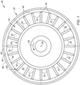
FIG. 1 is a schematic illustration of a rotor section for a gas turbine engine powerplant. -
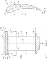
FIG. 2 is a partial schematic side sectional illustration of the rotor section. -
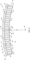
FIG. 3 is a sectional illustration of a rotor blade along line 3-3 inFIG. 2 . -
FIG. 4 is a partial schematic side sectional illustration of a multi-material abradable shroud. -
FIG. 5 is a partial schematic cross-sectional illustration of the abradable shroud. -
FIG. 6 is a partial schematic plan view illustration of an inner side of the abradable shroud. -
FIG. 6B is a partial schematic plan view illustration of the inner side of the abradable shroud with another pattern of protrusions. -
FIG. 7 is a partial schematic side sectional illustration of the rotor section during a self-clearancing operation. -
FIG. 8 is a partial schematic side sectional illustration of a shroud without support material during a self-clearancing operation. -
FIG. 9 is a partial schematic cross-sectional illustration of the abradable shroud with canted protrusions. -
FIGS. 10 and 11 are partial schematic cross-sectional illustrations of the abradable shroud with various protrusion arrangements. -
FIGS. 12-15 are partial schematic plan view illustrations of an inner side of the abradable shroud with various protrusion arrangements. -
FIGS. 16-18 are schematic illustrations of a protrusion with various cross-sectional geometries. -
FIG. 19 is a partial schematic side sectional illustration of the rotor section, where the abradable shroud has a multi-member shroud base. -
FIG. 20 is a partial schematic side sectional illustration of the abradable shroud ofFIG. 19 . -
FIG. 1 schematically illustrates arotor section 20 of a gas turbine engine powerplant for an aircraft. The aircraft may be an airplane, a helicopter, a drone (e.g., an unmanned aerial vehicle (UAV)) or any other manned or unmanned aerial vehicle or system. The powerplant may be configured as, or otherwise included as part of, a propulsion system for the aircraft. The powerplant, for example, may be a turbofan gas turbine engine, a turbojet gas turbine engine, a turboprop gas turbine engine or a turboshaft gas turbine engine. The powerplant may also or alternatively be configured as, or otherwise included as part of, an electrical power system for the aircraft. The powerplant, for example, may be an auxiliary power unit (APU) for the aircraft. The present disclosure, however, is not limited to such exemplary powerplants nor to aircraft applications. The powerplant, for example, may alternatively be an industrial gas turbine engine. - The
rotor section 20 may be configured as, or otherwise included as part of, a compressor section of the powerplant; e.g., a low pressure compressor (LPC) section. Therotor section 20 may alternatively be configured as, or otherwise included as part of, a fan section of the powerplant. The present disclosure, however, is not limited to the foregoing exemplary rotor sections. Therotor section 20 ofFIG. 1 includes a bladed rotor 22 (e.g., a compressor rotor or a fan rotor) and anabradable shroud 24 for thebladed rotor 22, which abradableshroud 24 may also be referred to as a blade outer air seal (BOAS). - The
bladed rotor 22 is rotatable in a first circumferential direction 26 (e.g., a counterclockwise direction, or alternatively a clockwise direction) about anaxis 28. Thisaxis 28 may be a centerline axis of therotor section 20 and itsrotor section members bladed rotor 22 includes a rotor base 30 (e.g., a disk or a hub) and a plurality of rotor blades 32 (e.g., airfoils or vanes). Therotor blades 32 are arranged circumferentially about therotor base 30 and theaxis 28 in a multi-material annular (e.g., circular) blade array. Therotor blades 32 are connected to therotor base 30. Each of therotor blades 32, for example, may be formed integral with or mechanically fastened, welded, brazed and/or otherwise attached to therotor base 30. - Referring to
FIG. 2 , each of therotor blades 32 projects radially out from therotor base 30 into and substantially radially across an annular flowpath 34 (see alsoFIG. 1 ) towards theabradable shroud 24, which flowpath 34 extends axially through therotor section 20. More particularly, each of therotor blades 32 projects spanwise along aspan line 36 of therespective rotor blade 32 out from aplatform 38 of therotor base 30 to an unsupporteddistal tip 40 of therespective rotor blade 32. Each of therotor blades 32 extends longitudinally along acamber line 42 of therespective rotor blade 32 from a leadingedge 44 of therespective rotor blade 32 to a trailingedge 46 of therespective rotor blade 32. Referring toFIG. 3 , each of therotor blades 32 extends laterally (e.g., in a direction perpendicular to the camber line 42) between and to a first (e.g., concave, pressure)side 48 of therespective rotor blade 32 and a second (e.g., convex, suction)side 50 of therespective rotor blade 32. These opposing lateral rotor blade sides 48 and 50 extends longitudinally along thecamber line 42 and meet at theleading edge 44 and the trailingedge 46. Referring toFIG. 2 , the leadingedge 44, the trailingedge 46, the bladefirst side 48 and the blade second side 50 (not visible inFIG. 2 ) each project spanwise / radially out from thebase platform 38 to therespective blade tip 40. - The
abradable shroud 24 extends axially along theaxis 28 between and to anupstream end 52 of theabradable shroud 24 and adownstream end 54 of theabradable shroud 24. Referring toFIG. 1 , theabradable shroud 24 extends circumferentially about (e.g., completely around) theaxis 28 providing theabradable shroud 24 with, for example, a full-hoop tubular geometry. Theabradable shroud 24 extends radially between and to a radialinner side 56 of theabradable shroud 24 and a radialouter side 58 of theabradable shroud 24. Referring toFIG. 2 , the shroudinner side 56 is disposed radially outboard of, but radially next to, thebladed rotor 22 and itsrotor blades 32. Eachblade tip 40 ofFIG. 2 , for example, is disposed radially inboard of theabradable shroud 24 and its shroudinner side 56, and may be (e.g., slightly) radially separated from theabradable shroud 24 and its shroudinner side 56 by a radial bladetip clearance gap 60. With this arrangement, theabradable shroud 24 and its shroudinner side 56 form a radial outer peripheral boundary of a portion of theflowpath 34 which extends at least axially along thebladed rotor 22 and itsrotor blades 32. In other words, theabradable shroud 24 and its shroudinner side 56 form the radial outer peripheral boundary of at least the portion of theflowpath 34 into which therotor blades 32 are located. - Referring to
FIG. 1 , theabradable shroud 24 may be configured as a single, unitary body circumferentially about theaxis 28. Alternatively, theabradable shroud 24 may include a plurality of arcuate shroud segments; see dashed lines. These shroud segments are arranged circumferentially end-to-end in an annular segment array to collectively form theabradable shroud 24 circumferentially about theaxis 28. - Referring to
FIG. 4 , theabradable shroud 24 includes a shroud base 62 (e.g., a backing plate, a support member, etc.) and a multi-materialabradable coating system 64. Theabradable shroud 24 ofFIG. 4 also includes one or more shroud mounts 66 (schematically shown inFIG. 4 ). These shroud mounts 66 are arranged at the shroudouter side 58 and are connected to (e.g., formed integral with or otherwise attached to) theshroud base 62. The shroud mounts 66 are configured to attach theabradable shroud 24 to a stationary support structure 68 (e.g., a case, a frame) of the powerplant. Examples of the shroud mounts 66 include, but are not limited to, mounting hooks, mounting flanges, mounting rims, and the like. - The
shroud base 62 extends axially along theaxis 28 between and to the shroudupstream end 52 and the shrouddownstream end 54. Theshroud base 62 extends radially between and to a radialinner side 70 of theshroud base 62 and a radialouter side 72 of theshroud base 62, where the shroud mounts 66 may be connected to theshroud base 62 at the baseouter side 72. Referring toFIG. 5 , theshroud base 62 extends circumferentially about theaxis 28. More particularly, where theabradable shroud 24 is configured as the single, unitary body, theshroud base 62 may extend completely around theaxis 28. Where theabradable shroud 24 is formed by the array of shroud segments, eachshroud base 62 included in a respective one of the shroud segments may extend partially about theaxis 28. Thisshroud base 62 is formed from a stiff, high strength and/or durable shroud base material such as metal or a polymer composite. Examples of the metal include, but are not limited to, an aluminum alloy, steel (e.g., stainless steel), a nickel (Ni) alloy, and a titanium (Ti) alloy. The polymer composite may include reinforcement material (e.g., carbon fibers) embedded within a polymer matrix. The polymer matrix may be a thermoset (e.g., epoxy) or a thermoplastic. Examples of the thermoplastic include, but are not limited to, polyetheretherketone (PEEK), polyetherketoneketone (PEKK), and polyaryletherketone (PAEK). - Referring to
FIGS. 4 and5 , thecoating system 64 is disposed at the baseinner side 70 and forms the shroudinner side 56. Thecoating system 64 ofFIGS. 4 and5 , for example, is connected (e.g., bonded) to theshroud base 62 at its baseinner side 70, and thecoating system 64 projects in a radial inward direction (e.g., towards theaxis 28, away from the shroud base 62) to the shroudinner side 56. Thecoating system 64 may cover an entirety of (or alternatively one or more select portions of) theshroud base 62 and its baseinner side 70. Thecoating system 64 ofFIG. 4 , for example, extends axially along the baseinner side 70 between and to the shroudupstream end 52 and the shrouddownstream end 54. Thecoating system 64 ofFIG. 5 extends circumferentially along a circumferential length of the baseinner side 70. For example, where theabradable shroud 24 is configured as the single, unitary body, thecoating system 64 may extend completely around theaxis 28. Where theabradable shroud 24 is formed by the array of shroud segments, the abradable coating of each shroud segment may extend circumferentially about theaxis 28 between opposing circumferential sides of the respective shroud segment. Thecoating system 64 ofFIGS. 4 and5 includes a plurality ofprotrusions 74A-D (generally referred to as "74") and asupport material 76. - Referring to
FIG. 6 , theprotrusions 74A-D are arranged into one or more circumferentially extendingarrays 78A-D (generally referred to as "78"); e.g., annular arrays, arcuate arrays, etc. Within each of theseprotrusion arrays 78, therespective protrusions 74 are arranged side-by-side circumferentially about theaxis 28 and may be (e.g., completely) axially aligned along theaxis 28. Each circumferentially neighboring (e.g., adjacent) pair of theprotrusions 74 within eachprotrusion array 78 are circumferentially spaced apart by acircumferential gap 80; e.g., channel, slot, etc. Thiscircumferential gap 80 extends circumferentially between and is formed by the respective circumferentially neighboring pair of theprotrusions 74. - Each axially neighboring pair of the
protrusion arrays 78 are axially spaced apart by an axial distance. With this arrangement, circumferentially aligned (or overlapping)protrusions 74 in each axially neighboring pair of theprotrusion arrays 78 are axially spaced apart by a respectiveaxial gap 82; e.g., channel, slot, etc. For example, each pair of circumferentially aligned (or overlapping)protrusions axial gap 82. Each pair of circumferentially aligned (or overlapping)protrusions axial gap 82. Each pair of circumferentially aligned (or overlapping)protrusions axial gap 82. - Referring to
FIGS. 4 and5 , each of theprotrusions 74 is connected to (e.g., bonded to) theshroud base 62. Each of theprotrusions 74 may project radially inward from theshroud base 62 to the shroudinner side 56. More particularly, each of theprotrusions 74 ofFIGS. 4 and5 projects spanwise along a span line 84 (e.g., a radially extending centerline) of therespective protrusion 74 out from the baseinner side 70 to a distalinner end 86 of therespective protrusion 74, which protrusioninner end 86 is disposed at and partially forms the shroudinner side 56. Each of theprotrusions 74 is formed from a stiff and/or erosion resistant abradable material such as a polymer resin; e.g., thermoset material or thermoplastic material. In some embodiments, the abradable material may also include an additive within the polymer resin to improve abradability and/or lower stiffness; e.g., to reduce rub forces. - The
support material 76 is configured to structurally support theprotrusions 74. Thesupport material 76 ofFIG. 4 , for example, completely (or alternatively partially) fills each of theaxial gaps 82 between axially neighboringprotrusions 74. More particularly, thesupport material 76 ofFIG. 4 extends axially between and may be connected to (e.g., bonded to) each axially neighboring pair of theprotrusions 74. Similarly, thesupport material 76 ofFIG. 5 completely (or alternatively partially) fills each of thecircumferential gaps 80 between circumferentially neighboringprotrusions 74. More particularly, thesupport material 76 ofFIG. 5 extends circumferentially between and may be connected to (e.g., bonded to) each circumferentially neighboring pair of theprotrusions 74. With this arrangement, referring toFIG. 6 , thesupport material 76 may completely (or alternatively partially) surround one or more or all of theprotrusions 74. Thesupport material 76 ofFIG. 6 , for example, extends around an exterior perimeter of (e.g., a circumference of) each of theprotrusions 74. Theprotrusions 74 may thereby be circumferentially and/or axially embedded within a matrix of thesupport material 76. - Referring to
FIGS. 4 and5 , thesupport material 76 is connected to (e.g., bonded to) theshroud base 62, and may partially form the shroudinner side 56. Thesupport material 76 ofFIGS. 4 and5 , for example, projects radially inward from the baseinner side 70, along sides of theprotrusions 74, to (or alternatively partially towards) the shroudinner side 56. With this arrangement, at least (or only) thesupport material 76 and the protrusion inner ends 86 may collectively form the shroudinner side 56. Thesupport material 76 may be a polymeric material such as an elastomeric material, which is different than the abradable material. Examples of the elastomeric material include, but are not limited to, nitrile rubber, butyl rubber, polyurethane, polyisoprene, butadiene, synthetic rubber, styrene-butadiene, neoprene, polybutadiene, fluoroelastomer, ethylene propylene rubber, natural rubber, ethylene-propylene diene monomer (EPDM), silicon rubber, chloroprene, isoprene, and perfluoroelastomer such as FFKM. - During rotor section operation, referring to
FIG. 7 , thebladed rotor 22 may self-clearance within theabradable shroud 24 by rubbing away a portion of thecoating system 64 at the shroudinner side 56. During this rubbing, one or more of the rotor blades 32 (one visible inFIG. 7 ) contacts thecoating system 64 and one or more of itsprotrusions 74. As therotor blade 32 ofFIG. 7 contacts a respective one of theprotrusions 74, therotor blade 32 exerts a lateral (e.g., circumferential or tangential) force against therespective protrusion 74 at its protrusioninner end 86 and may thereby subject therespective protrusion 74 to a relatively large moment. A portion of thesupport material 76 circumferentially adjacent (and rotationally behind) therespective protrusion 74 provides a support structure to at least partially reduce the load on therespective protrusion 74. Therotor blade 32 ofFIG. 7 may thereby break off an end portion of therespective protrusion 74 as well as remove a corresponding portion of thesupport material 76. The radial clearance between theblade tips 40 and the 1 Clearance shroud inner side 54' may thereby be relatively small. By contrast, if theabradable shroud 24 was configured without thesupport material 76 as shown inFIG. 8 for example, the moment imparted on therespective protrusion 74 may cause thatprotrusion 74 to also break off and/or otherwise fracture at its base; e.g., at or about the baseinner side 70. The radial clearance between theblade tips 40 and the 1 Clearance shroud inner side may thereby be relatively large. - In some embodiments, referring to
FIG. 5 , eachprotrusion 74 and itsprotrusion span line 84 may be arranged perpendicular to theshroud base 62 and its baseinner side 70 at a location of thatprotrusion 74. In other embodiments, referring toFIG. 9 , eachprotrusion 74 and itsprotrusion span line 84 may be angularly offset from theshroud base 62 and its baseinner side 70 at a location of thatprotrusion 74 by an offsetangle 88. This offsetangle 88 is a non-zero acute angle greater than, for example, forty-five degrees (45°), sixty degrees (60°) or seventy-five degrees (75°). Here, theprotrusions 74 are canted in a direction with the firstcircumferential direction 26 of the rotation of thebladed rotor 22 about theaxis 28. The protrusioninner end 86 of eachprotrusion 74 ofFIG. 9 , for example, is circumferentially offset in the firstcircumferential direction 26 from a base of thatrespective protrusion 74. With this arrangement, the blade loading against theprotrusions 74 may be reduced during rotor tip rub. - Referring to
FIGS. 10 and 11 , each of theprotrusions 74 has alateral protrusion width 90; e.g., a width between opposing circumferential sides of therespective protrusion 74. In some embodiments, referring toFIG. 10 , thelateral protrusion width 90 may be uniform (e.g., constant) as at least a portion or an entirety of therespective protrusion 74 projects in the radial inward direction; e.g., from the baseinner side 70 to the protrusioninner end 86. In other embodiments, referring toFIG. 11 , thelateral protrusion width 90 may change (e.g., decrease) as at least a portion or an entirety of therespective protrusion 74 projects in the radial inward direction; e.g., from the baseinner side 70 to the protrusioninner end 86. Eachprotrusion 74 ofFIG. 11 , in particular, has a laterally tapered geometry. - Referring to
FIGS. 10 and 11 , eachcircumferential gap 80 has alateral gap width 92; e.g., a width between a respective circumferentially neighboring pair of theprotrusions 74. Thislateral gap width 92 at or near the baseinner side 70 may be equal to or greater than thelateral protrusion width 90 of one or both of theprotrusions 74 forming that respectivecircumferential gap 80 at or near the baseinner side 70. However, it is contemplated thelateral gap width 92 may alternatively be smaller than thelateral protrusion width 90 in other embodiments depending on, for example, a density requirement for thesupport material 76. - In some embodiments, referring to
FIG. 6 , therespective protrusions 74 in eachprotrusion array 78 may be (e.g., completely) axially aligned along theaxis 28. For example, an axial center and/or an axial end of eachprotrusion 74 in therespective protrusion array 78 may be located on a common reference plane perpendicular to theaxis 28. Alternatively, therespective protrusions 74 in eachprotrusion array 78 may be slightly axially offset along theaxis 28. In other embodiments, two or more of theprotrusion arrays 78 may axially overlap one another as shown, for example, inFIG. 6B . For example, theprotrusions 74 in theprotrusion array 78A' axially overlap theprotrusions 74 in theprotrusion arrays protrusions 74 in theprotrusion array 78B' axially overlap theprotrusions 74 in theprotrusion arrays protrusions 74 in theprotrusion array 78C' axially overlap theprotrusions 74 in theprotrusion arrays - In some embodiments, referring to
FIG. 6 , one or more or all of theprotrusions 74 may each be configured as arib 94; e.g., an axially elongated member. In other embodiments, referring toFIGS. 12-15 , one or more of all of theprotrusions 74 may alternatively each be configured as a pedestal 96. - In some embodiments, referring to
FIGS. 16 and 17 , one or more or all of theprotrusions 74 may each have an elongated cross-sectional geometry. Examples of this elongated geometry include, but are not limited to, a rectangular cross-sectional geometry (seeFIG. 16 ) and an oval cross-sectional geometry (seeFIG. 17 ), a racetrack shaped cross-sectional geometry, or the like. - In some embodiments, referring to
FIG. 16 , one or more or all of theprotrusions 74 may each have a polygonal cross-sectional geometry. Examples of this polygonal geometry include, but are not limited to, a rectangular cross-sectional geometry (seeFIG. 16 ), a square cross-sectional geometry, a triangular cross-sectional geometry, a trapezoidal cross-sectional geometry, a parallelogram cross-sectional geometry, or the like. - In some embodiments, referring to
FIG. 18 , one or more or all of theprotrusions 74 may each have a circular cross-sectional geometry. - For ease of description, the
shroud base 62 is generally described above as a monolithic body; e.g., seeFIGS. 2 and4 . Theshroud base 62, for example, may be formed as a single unitary body from the shroud base material. It is contemplated, however, theshroud base 62 may alternatively be formed from different members which are connected (e.g., bonded) together to collectively form theshroud base 62. For example, referring toFIGS. 19 and20 ,shroud base 62 includes abase substrate 98 and a coating system backing 100. Here, the coating system backing 100 is a thin sheet of material which forms the baseinner side 70. With such an arrangement, thecoating system 64 and itsmembers abrasion module 102; e.g., a cartridge. Thisabrasion module 102 and its coating system backing 100 may then be bonded and/or otherwise connected to thebase substrate 98 to provide theabradable shroud 24. - The
abradable shroud 24 and itscoating system 64 may be formed using various manufacturing techniques. Thecoating system 64, for example, may be formed (e.g., printed) onto theshroud base 62 using additive manufacturing techniques. The present disclosure, however, is not limited to any particular manufacturing techniques. - While various embodiments of the present disclosure have been described, it will be apparent to those of ordinary skill in the art that many more embodiments and implementations are possible within the scope of the disclosure. For example, the present disclosure as described herein includes several aspects and embodiments that include particular features. Although these features may be described individually, it is within the scope of the present disclosure that some or all of these features may be combined with any one of the aspects and remain within the scope of the disclosure. Accordingly, the present disclosure is not to be restricted except in light of the attached claims and their equivalents.
Claims (15)
- An apparatus for a gas turbine engine, comprising:a shroud (24) including a base (62) and an abradable coating system (64);the base (62) extending axially along and circumferentially about an axis (28), the base (62) extending radially between a base inner side (70) and a base outer side (72);the abradable coating system (64) bonded to and covering the base (62) at the base inner side (70), and the abradable coating system (64) including a plurality of protrusions (74) and an elastomeric material (76);the plurality of protrusions (74) arranged circumferentially about the axis (28) in a circumferentially extending array (78), each of the plurality of protrusions (74) projecting in a radial inward direction away from the base inner side (70) to a distal inner end (86), and each of the plurality of protrusions (74) comprising an abradable material; andthe elastomeric material (76) filling a gap (80) between each circumferentially neighboring pair of the plurality of protrusions (74).
- The apparatus of claim 1, wherein the plurality of protrusions (74) comprise a first protrusion (74), and the elastomeric material (76) surrounds the first protrusion (74).
- The apparatus of claim 1 or 2, wherein the shroud (24) extends radially between a shroud inner side (56) and a shroud outer side (58), and the shroud inner side (56) is collectively formed by the distal inner end (86) of a or the first protrusion (74) of the plurality of protrusions (74), and the elastomeric material (76).
- The apparatus of claim 1, 2 or 3, wherein the plurality of protrusions (74) include a or the first protrusion (74) and a second protrusion (74), and the elastomeric material (76) extends laterally between and is bonded to the first protrusion (74) and the second protrusion (74).
- The apparatus of any preceding claim, wherein a or the first protrusion (74) of the plurality of protrusions (74) projects radially from the base inner side (70) to the distal inner end (86) of the first protrusion (74), and the elastomeric material (76) projects radially to the base inner side (70) along the first protrusion (74).
- The apparatus of any preceding claim, wherein a or the first protrusion (74) of the plurality of protrusions (74) has a lateral protrusion width (90) at the base inner side (70), and the gap (80) formed by the first protrusion (74) has a lateral gap width (92) at the base inner side (70) that is equal to or greater than the lateral protrusion width (90).
- The apparatus of any preceding claim, wherein a or the first protrusion (74) of the plurality of protrusions (74) is configured as a pedestal (96).
- The apparatus of any of claims 1 to 6, wherein a or the first protrusion (74) of the plurality of protrusions (74) is configured as a rib (94).
- The apparatus of any preceding claim, wherein a or the first protrusion (74) of the plurality of protrusions (74) projects along a span line (84) in the radial inward direction away from the base inner side (70) to the distal inner end (86) of the first protrusion (74), and the span line (84) is perpendicular to the base inner side (70) and/or is angularly offset from the base inner side (70) by an included acute angle (88).
- The apparatus of any preceding claim, wherein a or the first protrusion (74) of the plurality of protrusions (74) has a or the lateral protrusion width (90), and the lateral protrusion width (90) is uniform as at least a portion of the first protrusion (74) projects radially in the radial inward direction away from the base inner side (70).
- The apparatus of any of claims 1 to 9, wherein a or the first protrusion (74) of the plurality of protrusions (74) has a or the lateral protrusion width (90), and the lateral protrusion width (90) changes as at least a portion of the first protrusion (74) projects radially in the radial inward direction away from the base inner side (70).
- The apparatus of claim, wherein a or the first protrusion (74) of the plurality of protrusions (74) has a circular cross-sectional geometry, an elongated cross-sectional geometry, or a polygonal cross-sectional geometry.
- The apparatus of any preceding claim, wherein:the plurality of protrusions (74) are a plurality of first protrusions (74), and the abradable coating system (64) further includes a plurality of second protrusions (74);the plurality of second protrusions (74) are arranged circumferentially about the axis (28) in a second circumferentially extending array (78), each of the plurality of second protrusions (74) projects in the radial inward direction away from the base inner side (70) to a second distal inner end (86), and each of the plurality of second protrusions (74) comprises the abradable material; andthe elastomeric material (76) fills a second gap (82) between each axially neighboring pair of one of the plurality of first protrusions (74) and one of the plurality of second protrusions (74).
- The apparatus of any preceding claim, further comprising:a bladed rotor (22) rotatable about the axis (28), the bladed rotor (22) including a rotor base (30) and a plurality of rotor blades (32) arranged circumferentially around rotor base (30);the abradable coating system (64) forming an outer peripheral boundary of a flowpath (34); andeach of the plurality of rotor blades (32) projecting radially out from the rotor base (30) into the flowpath (34) towards the abradable coating system (64).
- The apparatus of any preceding claim, wherein the plurality of protrusions (74) comprises:a plurality of upstream protrusions (74A) arranged circumferentially about the axis (28) in an upstream array (78A), each of the plurality of upstream protrusions (74A) projecting radially inward away from the base inner side (70), and each of the plurality of upstream protrusions (74A) comprising the abradable material; anda plurality of downstream protrusions (74B) arranged circumferentially about the axis (28) in a downstream array (78B), each of the plurality of downstream protrusions (74B) projecting radially inward away from the base inner side (70), and each of the plurality of downstream protrusions (74B) comprising the abradable material; andthe elastomeric material (76) extending circumferentially about the axis (28) and axially between the upstream array (78A) and the downstream array (78B), optionally wherein the elastomeric material (76) surrounds each of the plurality of upstream protrusions (74A) and/or the elastomeric material (76) surrounds each of the plurality of downstream protrusions (74B).
Applications Claiming Priority (1)
| Application Number | Priority Date | Filing Date | Title |
|---|---|---|---|
| US18/389,469 US20250154905A1 (en) | 2023-11-14 | 2023-11-14 | Multi-material abradable shroud for gas turbine engine rotor |
Publications (1)
| Publication Number | Publication Date |
|---|---|
| EP4556685A1 true EP4556685A1 (en) | 2025-05-21 |
Family
ID=93562896
Family Applications (1)
| Application Number | Title | Priority Date | Filing Date |
|---|---|---|---|
| EP24213111.8A Pending EP4556685A1 (en) | 2023-11-14 | 2024-11-14 | Multi-material abradable shroud for gas turbine engine rotor |
Country Status (2)
| Country | Link |
|---|---|
| US (1) | US20250154905A1 (en) |
| EP (1) | EP4556685A1 (en) |
Citations (6)
| Publication number | Priority date | Publication date | Assignee | Title |
|---|---|---|---|---|
| GB1361814A (en) * | 1970-12-21 | 1974-07-30 | Clevite Corp | Powder metal honeycomb |
| US20080274336A1 (en) * | 2006-12-01 | 2008-11-06 | Siemens Power Generation, Inc. | High temperature insulation with enhanced abradability |
| US20090297331A1 (en) * | 2008-04-23 | 2009-12-03 | Snecma | Turbomachine casing including a device for preventing instability during contact between the casing and the rotor |
| US8475121B1 (en) * | 2011-01-17 | 2013-07-02 | Florida Turbine Technologies, Inc. | Ring segment for industrial gas turbine |
| US20150354393A1 (en) * | 2014-06-10 | 2015-12-10 | General Electric Company | Methods of manufacturing a shroud abradable coating |
| US20200277871A1 (en) * | 2018-07-12 | 2020-09-03 | Rolls-Royce North American Technologies, Inc. | Non-continuous abradable coatings |
Family Cites Families (2)
| Publication number | Priority date | Publication date | Assignee | Title |
|---|---|---|---|---|
| EP3822004A1 (en) * | 2019-11-14 | 2021-05-19 | Rolls-Royce Corporation | Fused filament fabrication of abradable coatings |
| GB201916958D0 (en) * | 2019-11-21 | 2020-01-08 | Rolls Royce Plc | Abradable sealing element |
-
2023
- 2023-11-14 US US18/389,469 patent/US20250154905A1/en active Pending
-
2024
- 2024-11-14 EP EP24213111.8A patent/EP4556685A1/en active Pending
Patent Citations (6)
| Publication number | Priority date | Publication date | Assignee | Title |
|---|---|---|---|---|
| GB1361814A (en) * | 1970-12-21 | 1974-07-30 | Clevite Corp | Powder metal honeycomb |
| US20080274336A1 (en) * | 2006-12-01 | 2008-11-06 | Siemens Power Generation, Inc. | High temperature insulation with enhanced abradability |
| US20090297331A1 (en) * | 2008-04-23 | 2009-12-03 | Snecma | Turbomachine casing including a device for preventing instability during contact between the casing and the rotor |
| US8475121B1 (en) * | 2011-01-17 | 2013-07-02 | Florida Turbine Technologies, Inc. | Ring segment for industrial gas turbine |
| US20150354393A1 (en) * | 2014-06-10 | 2015-12-10 | General Electric Company | Methods of manufacturing a shroud abradable coating |
| US20200277871A1 (en) * | 2018-07-12 | 2020-09-03 | Rolls-Royce North American Technologies, Inc. | Non-continuous abradable coatings |
Also Published As
| Publication number | Publication date |
|---|---|
| US20250154905A1 (en) | 2025-05-15 |
Similar Documents
| Publication | Publication Date | Title |
|---|---|---|
| EP1865154B1 (en) | Aerofoil stage and a seal for bridging gaps between adjacent airfoils | |
| US4451205A (en) | Rotor blade assembly | |
| EP2239422B1 (en) | Sealing arrangement for a gas turbine engine | |
| US20120128482A1 (en) | Outer shell sector for a bladed ring for an aircraft turbomachine stator, including vibration damping shims | |
| US6340286B1 (en) | Rotary machine having a seal assembly | |
| US20060099070A1 (en) | Turbine engine disk spacers | |
| US9097124B2 (en) | Gas turbine engine stator vane assembly with inner shroud | |
| US20090148277A1 (en) | Gas Turbine Engines and Related Systems Involving Blade Outer Air Seals | |
| EP1895108A2 (en) | Angel wing abradable seal and sealing method | |
| US9303516B2 (en) | Movable blade for a turbomachine | |
| US8876458B2 (en) | Blade outer air seal assembly and support | |
| US9752593B2 (en) | Method of manufacturing a gas turbine engine having a fan track liner with an abradable layer | |
| US10895159B2 (en) | Removable anti-wear part for blade tip | |
| JP5427398B2 (en) | Turbomachined sectorized nozzle | |
| EP3486496B1 (en) | Fan for gas turbine engines having mid-span shroud | |
| WO2013185044A1 (en) | Fan blade platform | |
| CN102654141A (en) | Segmented shroud assembly suitable for compensating a rotor misalignment relative to the stator | |
| EP3409885B1 (en) | Deflection spring seal | |
| USRE33954E (en) | Rotor blade assembly | |
| EP2636852B1 (en) | Hybrid inner air seal for gas turbine engines | |
| US20080044284A1 (en) | Segmented fluid seal assembly | |
| US20090104025A1 (en) | Gas Turbine Engines and Related Systems Involving Blade Outer Air Seals | |
| EP3839215B1 (en) | Rotor blade | |
| US20250154905A1 (en) | Multi-material abradable shroud for gas turbine engine rotor | |
| EP3078813B1 (en) | Fan section comprising a blade platform seal with leading edge winglet and associated gas turbine engine |
Legal Events
| Date | Code | Title | Description |
|---|---|---|---|
| PUAI | Public reference made under article 153(3) epc to a published international application that has entered the european phase |
Free format text: ORIGINAL CODE: 0009012 |
|
| STAA | Information on the status of an ep patent application or granted ep patent |
Free format text: STATUS: THE APPLICATION HAS BEEN PUBLISHED |
|
| AK | Designated contracting states |
Kind code of ref document: A1 Designated state(s): AL AT BE BG CH CY CZ DE DK EE ES FI FR GB GR HR HU IE IS IT LI LT LU LV MC ME MK MT NL NO PL PT RO RS SE SI SK SM TR |
|
| STAA | Information on the status of an ep patent application or granted ep patent |
Free format text: STATUS: REQUEST FOR EXAMINATION WAS MADE |
|
| 17P | Request for examination filed |
Effective date: 20251121 |