EP4556642A1 - Telescopic bubbler - Google Patents
Telescopic bubbler Download PDFInfo
- Publication number
- EP4556642A1 EP4556642A1 EP23842450.1A EP23842450A EP4556642A1 EP 4556642 A1 EP4556642 A1 EP 4556642A1 EP 23842450 A EP23842450 A EP 23842450A EP 4556642 A1 EP4556642 A1 EP 4556642A1
- Authority
- EP
- European Patent Office
- Prior art keywords
- aerator
- mounting seat
- telescopic
- water
- ball head
- Prior art date
- Legal status (The legal status is an assumption and is not a legal conclusion. Google has not performed a legal analysis and makes no representation as to the accuracy of the status listed.)
- Pending
Links
Images







Classifications
-
- E—FIXED CONSTRUCTIONS
- E03—WATER SUPPLY; SEWERAGE
- E03C—DOMESTIC PLUMBING INSTALLATIONS FOR FRESH WATER OR WASTE WATER; SINKS
- E03C1/00—Domestic plumbing installations for fresh water or waste water; Sinks
- E03C1/02—Plumbing installations for fresh water
- E03C1/08—Jet regulators or jet guides, e.g. anti-splash devices
-
- B—PERFORMING OPERATIONS; TRANSPORTING
- B05—SPRAYING OR ATOMISING IN GENERAL; APPLYING FLUENT MATERIALS TO SURFACES, IN GENERAL
- B05B—SPRAYING APPARATUS; ATOMISING APPARATUS; NOZZLES
- B05B1/00—Nozzles, spray heads or other outlets, with or without auxiliary devices such as valves, heating means
- B05B1/14—Nozzles, spray heads or other outlets, with or without auxiliary devices such as valves, heating means with multiple outlet openings; with strainers in or outside the outlet opening
- B05B1/16—Nozzles, spray heads or other outlets, with or without auxiliary devices such as valves, heating means with multiple outlet openings; with strainers in or outside the outlet opening having selectively- effective outlets
- B05B1/1627—Nozzles, spray heads or other outlets, with or without auxiliary devices such as valves, heating means with multiple outlet openings; with strainers in or outside the outlet opening having selectively- effective outlets with a selecting mechanism comprising a gate valve, a sliding valve or a cock
- B05B1/1636—Nozzles, spray heads or other outlets, with or without auxiliary devices such as valves, heating means with multiple outlet openings; with strainers in or outside the outlet opening having selectively- effective outlets with a selecting mechanism comprising a gate valve, a sliding valve or a cock by relative rotative movement of the valve elements
- B05B1/1645—Nozzles, spray heads or other outlets, with or without auxiliary devices such as valves, heating means with multiple outlet openings; with strainers in or outside the outlet opening having selectively- effective outlets with a selecting mechanism comprising a gate valve, a sliding valve or a cock by relative rotative movement of the valve elements the outlets being rotated during selection
- B05B1/1654—Nozzles, spray heads or other outlets, with or without auxiliary devices such as valves, heating means with multiple outlet openings; with strainers in or outside the outlet opening having selectively- effective outlets with a selecting mechanism comprising a gate valve, a sliding valve or a cock by relative rotative movement of the valve elements the outlets being rotated during selection about an axis parallel to the liquid passage in the stationary valve element
-
- B—PERFORMING OPERATIONS; TRANSPORTING
- B05—SPRAYING OR ATOMISING IN GENERAL; APPLYING FLUENT MATERIALS TO SURFACES, IN GENERAL
- B05B—SPRAYING APPARATUS; ATOMISING APPARATUS; NOZZLES
- B05B15/00—Details of spraying plant or spraying apparatus not otherwise provided for; Accessories
- B05B15/60—Arrangements for mounting, supporting or holding spraying apparatus
- B05B15/65—Mounting arrangements for fluid connection of the spraying apparatus or its outlets to flow conduits
- B05B15/652—Mounting arrangements for fluid connection of the spraying apparatus or its outlets to flow conduits whereby the jet can be oriented
- B05B15/654—Mounting arrangements for fluid connection of the spraying apparatus or its outlets to flow conduits whereby the jet can be oriented using universal joints
-
- B—PERFORMING OPERATIONS; TRANSPORTING
- B05—SPRAYING OR ATOMISING IN GENERAL; APPLYING FLUENT MATERIALS TO SURFACES, IN GENERAL
- B05B—SPRAYING APPARATUS; ATOMISING APPARATUS; NOZZLES
- B05B15/00—Details of spraying plant or spraying apparatus not otherwise provided for; Accessories
- B05B15/70—Arrangements for moving spray heads automatically to or from the working position
- B05B15/72—Arrangements for moving spray heads automatically to or from the working position using hydraulic or pneumatic means
- B05B15/74—Arrangements for moving spray heads automatically to or from the working position using hydraulic or pneumatic means driven by the discharged fluid
-
- E—FIXED CONSTRUCTIONS
- E03—WATER SUPPLY; SEWERAGE
- E03C—DOMESTIC PLUMBING INSTALLATIONS FOR FRESH WATER OR WASTE WATER; SINKS
- E03C1/00—Domestic plumbing installations for fresh water or waste water; Sinks
- E03C1/02—Plumbing installations for fresh water
- E03C1/04—Water-basin installations specially adapted to wash-basins or baths
- E03C1/0404—Constructional or functional features of the spout
- E03C1/0405—Constructional or functional features of the spout enabling multiple spray patterns
-
- B—PERFORMING OPERATIONS; TRANSPORTING
- B05—SPRAYING OR ATOMISING IN GENERAL; APPLYING FLUENT MATERIALS TO SURFACES, IN GENERAL
- B05B—SPRAYING APPARATUS; ATOMISING APPARATUS; NOZZLES
- B05B7/00—Spraying apparatus for discharge of liquids or other fluent materials from two or more sources, e.g. of liquid and air, of powder and gas
- B05B7/02—Spray pistols; Apparatus for discharge
- B05B7/04—Spray pistols; Apparatus for discharge with arrangements for mixing liquids or other fluent materials before discharge
- B05B7/0416—Spray pistols; Apparatus for discharge with arrangements for mixing liquids or other fluent materials before discharge with arrangements for mixing one gas and one liquid
- B05B7/0425—Spray pistols; Apparatus for discharge with arrangements for mixing liquids or other fluent materials before discharge with arrangements for mixing one gas and one liquid without any source of compressed gas, e.g. the air being sucked by the pressurised liquid
-
- E—FIXED CONSTRUCTIONS
- E03—WATER SUPPLY; SEWERAGE
- E03C—DOMESTIC PLUMBING INSTALLATIONS FOR FRESH WATER OR WASTE WATER; SINKS
- E03C1/00—Domestic plumbing installations for fresh water or waste water; Sinks
- E03C1/02—Plumbing installations for fresh water
- E03C1/04—Water-basin installations specially adapted to wash-basins or baths
- E03C2001/0414—Water-basin installations specially adapted to wash-basins or baths allowing different orientations of the spout or the outlet nozzle
-
- E—FIXED CONSTRUCTIONS
- E03—WATER SUPPLY; SEWERAGE
- E03C—DOMESTIC PLUMBING INSTALLATIONS FOR FRESH WATER OR WASTE WATER; SINKS
- E03C1/00—Domestic plumbing installations for fresh water or waste water; Sinks
- E03C1/02—Plumbing installations for fresh water
- E03C1/08—Jet regulators or jet guides, e.g. anti-splash devices
- E03C2001/082—Outlets connected by an universal joint
Definitions
- the present disclosure relates to a water outlet device, and in particular relates to an aerator.
- An aerator is a device that has a foaming effect and conserves water.
- the aerator allows water and air that flow through to be completely mixed, an introduction of air greatly improves flushing power of the water, water consumption is effectively reduced, and the water is conserved.
- the aerators in the existing techniques are generally fixedly installed at a water outlet of a faucet, if the faucet is fixed, the aerator is also fixed, and an angle of the water outlet cannot be adjusted.
- an aerator in the existing techniques is divided into a mounting seat and an aerator body, the mounting seat is fixedly connected to an water outlet of the faucet, and the aerator body is connected to the mounting seat by a ball head to achieve swinging, so that the aerator body can swing relative to the faucet to adjust the angle of the water outlet.
- a connecting rod of the ball head in this solution is exposed, which is unattractive, and a consistency in an appearance the faucet is destroyed.
- the main technical problem to be resolved by the present disclosure is to provide an aerator, the aerator can swing to adjust a water outflow direction when water flows, and a consistency in an appearance of the aerator is also not damaged when the water stops.
- a telescopic aerator it comprises: an aerator body, a telescopic assembly and a mounting seat; the telescopic assembly is swingably connected to the aerator body through a ball head; and the telescopic assembly drives the aerator body to move to a first position or a second position along an axial direction of the mounting seat when water stops and the water flows;
- the aerator body When the aerator body is in the first position, the aerator body forms a positioning cooperation with the mounting seat along a swinging direction of the ball head; and when the aerator body is in the second position, the aerator body is separated from the mounting seat by a preset distance, so that the aerator body is released from the positioning cooperation with the mounting seat along the swinging direction of the ball head.
- the aerator body is connected to the ball head through a fixed ring.
- the fixed ring is exposed on a side of the aerator body facing the mounting seat.
- the telescopic assembly comprises a sealing portion hermetically sealed to the mounting seat and a connecting portion connected to the ball head, a groove is disposed between the sealing portion and the connecting portion, and an opening of the groove faces downward.
- the mounting seat comprises a through passage for the connecting portion to pass through, and when the aerator body is in the second position, a side wall of the through passage is inserted into the groove along the opening.
- a guiding wall is disposed in the mounting seat, and the guiding wall guides the fixed ring during a movement of the aerator body from the second position to the first position.
- the guiding wall surrounds to form a receiving chamber with an opening at two ends, and the receiving chamber comprises a structure with a diameter of the opening that gradually increases from one end away from the aerator body to the other end.
- the telescopic assembly comprises a piston and a spring, and the piston is movably disposed in the mounting seat, one side of the piston along an axial direction of the mounting seat contacts the water flow, and the other side is connected to an inner wall of the mounting seat through the spring.
- a side of the piston facing the ball head comprises a mounting hole configured for mounting the ball head; and the mounting hole and the ball head are fixed by a threaded connection.
- the present disclosure further discloses a telescopic aerator, it comprises: an aerator body, a telescopic assembly and a mounting seat; the telescopic assembly is disposed in the aerator body and is swingably connected to the mounting seat through a ball head; and the telescopic assembly drives the aerator body to move to a first position or a second position along an axial direction of the mounting seat when water stops and the water flows; and
- the aerator body When the aerator body is in the second position, the aerator body is separated from the mounting seat by a preset distance.
- the mounting seat is connected to the aerator body through a fixed ring.
- the fixed ring is exposed on a side of the mounting seat facing the aerator body.
- the telescopic assembly comprises a sealing portion hermetically sealed to the mounting seat and a connecting portion connected to the ball head, a groove is disposed between the sealing portion and the connecting portion, and an opening of the groove faces upward.
- the aerator body comprises a guiding wall, and the guiding wall guides the fixed ring during a movement of the aerator body from the second position to the first position.
- the telescopic assembly comprises a piston, a spring and a piston cylinder, the piston is movably disposed in the piston cylinder, one side of the piston along an axial direction of the aerator body contacts the water flow, and the other side is connected to an inner wall of the piston cylinder through the spring.
- it further comprises a damping mechanism, which is used for the aerator to be hovered within a swinging range in a water flowing sate.
- the damping mechanism is disposed in the mounting seat and comprises a friction base, a friction cylinder pad and a second spring.
- the present disclosure provides the telescopic aerator, which allows a piston component to drive the aerator body to move between the first position and the second position through the water pressure changes when the water stops and the water flows, consequently, the aerator body is separated from the mounting seat by the preset distance when the water flows, so that the aerator body is released from a positioning cooperation with the mounting seat along a swinging direction of the ball head.
- the aerator body can have a function of adjusting the angle of the water outflow by swinging.
- the aerator body forms the positioning cooperation with the mounting seat along the swinging direction of the ball head, ensuring the consistency in the appearance of the aerator in the water stop state.
- connection can be a wall-mountable connection, a detachable connection, an integrated connection, a mechanical connection, an electrical connection, a direct connection, an indirect connection via an intermediate medium, or a communication between inner portions of two elements, and the specific meaning of the terms in the present disclosure can be understood in specific conditions for those of ordinary skill in the art.
- this embodiment provides a telescopic aerator, which comprises: an aerator body 1, a telescopic assembly 2 and a mounting seat 3; the telescopic assembly 2 is swingably connected to the aerator body 1 through a ball head 4; the telescopic assembly 2 drives the aerator body 1 to move to a first position or a second position along an axial direction of the mounting seat 3 under water pressure changes when the water stops and the water flows; when the aerator body 1 is in the first position, the aerator body 1 abuts the mounting seat 3, and in this embodiment, a fixed ring connected to the ball head 4 is accommodated in the mounting seat 3 synchronously; and when the aerator body 1 is in the second position, the aerator body 1 is separated from the mounting seat 3 by a preset distance, and the fixed ring 11 connected to the aerator body 1 and the ball head 4 is exposed outside of the mounting seat 3 synchronously.
- the aerator body 1 is driven to move by the water pressure changes when the water stops and the water flows.
- an electrical signal can be generated by water flow changes when the water stops and the water flows, and a controller controls an electromagnetic unit or a mechanical unit to drive the aerator body 1 to move using electromagnetic force or mechanical force through the electrical signal.
- the aforementioned aerator allows a piston component to drive the aerator body 1 to move between the first position and the second position through the water pressure changes when the water stops the and the water flows, consequently, when the water flows, the aerator body 1 is separated from the mounting seat 3 by the preset distance, so that the aerator body 1 can swing to adjust an angle of water outflow; and when the water stops, the aerator body 1 abuts the mounting seat 3, ensuring consistency in an appearance of the aerator in a water stop state.
- the mounting seat 3 and the aerator body comprise a guiding wall 31 configured for a guiding cooperation with the fixed ring 11 within in the first position.
- the guiding wall 31 surrounds to define a receiving chamber 32 with an opening at two ends, and the receiving chamber 32 has a structure with a diameter of the opening that gradually increases from one end away from the aerator body 1 to the other end. In this way, the aerator body 1 will accurately restored to the second position through a guiding effect of the guiding wall 31 during a movement.
- the fixed ring 11 has an inclined surface that fits the guiding wall 31.
- the telescopic assembly 2 and the ball head 4 comprise a water flow passage 5 for water passage. In this way, water can flow into the aerator body 1 from the water flow passage.
- the telescopic assembly 2 comprises a piston 21 and a spring 22, the piston 21 is movably disposed in the mounting seat 3, a side of the piston 21 along an axial direction of the mounting seat 3 contacts the water flow, and the other side is connected to an inner wall of the mounting seat 3 through the spring 22.
- the spring 22 is in a relatively loose state.
- the spring 22 is in a compressed state. At this time, if a water flowing state is converted to the water stop state, the water pressure applied to the piston 21 becomes smaller, and the spring 22 releases an elastic restoring force to drive the aerator body 1 to be restored to the first position.
- the mounting seat 3 comprises a through passage for the piston 21 to pass through, the through passage comprises a side wall 35 extending upward along a direction of the water flow, and in this embodiment, the side wall 35 further comprises the guiding wall 31 disposed on a lower end of the side wall 35 and stretching outward along a radial direction; the mounting seat 3 further comprises an outer peripheral wall 32 configured for connecting to a water outlet device; and the outer peripheral wall 32 comprises a thread.
- the outer peripheral wall 32 is connected to a bottom of the guiding wall 31 through a bottom wall 34, so that a first groove 33 with an opening facing upward is formed between the outer peripheral wall 32 and the guiding wall 31, and the spring 22 abuts the bottom wall 34; and the piston 21 comprises a sealing portion 211 hermetically sealed to the mounting seat 3 and a connecting portion 212 connected to the ball head 4, and a second groove 213 with an opening facing downward is formed between the sealing portion 211 and the connecting portion 212. Consequently, when the aerator body 1 is in the second position, the side wall 35 of the through passage is inserted into the second groove 213 through the opening.
- the sealing portion 211 comprises a groove disposed on an outer peripheral wall of the piston and a Y-shaped ring 23 installed in the groove.
- the connecting portion 212 comprises a thread connected to the ball head 4.
- a side of the piston 21 facing the ball head 4 comprises a mounting hole configured for mounting the ball head 4, and the mounting hole and the ball head 4 are fixed by a threaded connection.
- the Y-shaped ring 23 is disposed between the piston 21 and the side wall of the mounting seat 3.
- the aerator body 1 can be switched between two different water outflow sprays, and a switching process can be achieved by rotating the aerator body 1. Therefore, an inner side of the aerator body 1 further comprises a water inlet seat 12, a pressure cover 13, a sealing gasket 14 and a water dividing body 15, and the water inlet seat 12 is disposed between the ball head 4 and the water dividing body 15, so that the water flowing out of the water flow passage 5 can flow into the water dividing body 15 through the water inlet seat 12.
- the water dividing body 15 is fixedly connected to a shell 16 of the aerator body 1, an avoidance opening 131 is disposed on an axial center of the pressure cover 13 to enable a lower end of the water inlet seat 12 to pass through, and the lower end of the water inlet seat 12 passes through the avoidance opening 131 to be fixedly connected to the water dividing body 15 by a screw 121. Therefore, the shell 16 rotates to drive the water dividing body 15 and the water inlet seat 12 to rotate relative to the sealing gasket 14.
- the sealing gasket 14 is disposed between the pressure cover 13 and the water dividing body 15, and a downward-pressing spring 17 is disposed on a side of the pressure cover 13 away from the sealing gasket 14, and one end of the spring away from the pressure cover 13 abuts the water inlet seat 12.
- the water inlet seat 12 squeezes the downward-pressing spring 17 during a movement from a first position to a second position, so that the downward-pressing spring 17 drives the pressure cover 13 to downwardly press down the sealing gasket 14.
- the pressure cover 13 further comprises an annular water passage opening 132 on an outer side of the avoidance opening 131 along a radial direction.
- the water dividing body 15 comprises a first flow passage 151 and second flow passages 152, the second flow passages 152 are disposed at intervals along a circumferential direction, and the first flow passage 151 is disposed between two adjacent ones of the second flow passages 152.
- the first flow passage 151 and the second flow passages 152 are separated by a baffle 153.
- the water passage opening 132 is in communication with the first flow passage 151 and the second flow passages 152 simultaneously.
- the downward-pressing spring 17 When the shell 16 drives the water inlet seat 12 to rotate to the second position, the downward-pressing spring 17 is in a compressed state, and the sealing gasket 14 is squeezed by the pressure cover 13, thereby sealing the communication between the water passage opening 132 and the second flow passages 152.
- the second flow passages 152 of the water dividing body 15 are sealed, and the water flows out of the first flow passage 151.
- a steel sheet 154 is disposed on a water outlet of the first flow passage 151, and the water flows through fine holes on the steel sheet 154 to form multiple beams of delicate steel sheet water sprays.
- this embodiment differs from Embodiment 1 in that: the fixed ring 11 in Embodiment 1 is exposed on the side of the aerator body 1 facing the mounting seat 3, while in this embodiment, the fixed ring 11 as a whole is accommodated in the aerator body 1; as the fixed ring 11 is accommodated in the aerator body 1, the guiding wall 31 used to guide the fixed ring 11 in Embodiment 1 can also be excluded. Therefore, the side wall 35 in this embodiment does not comprise the guiding wall 31. The remainder aligns with Embodiment 1 and will not be repeated herein.
- this embodiment differs from Embodiment 1 in that: this embodiment comprises: an aerator body 10, a telescopic assembly 20 and a mounting seat 30; the telescopic assembly 20 is disposed in the aerator body 10 and is swingably connected to the mounting seat 30 through a ball head 40. That is: the ball head 40 is inverted, and the telescopic assembly 20 is disposed in the aerator body 10.
- the telescopic assembly 20 drives the aerator body 10 to move to the first position or the second position along an axial direction of the mounting seat 30 under the water pressure changes when the water stops and the water flows; when the aerator body 10 is in the first position, the aerator body 10 abuts the mounting seat 30; when the aerator body 10 is in the second position, the aerator body 10 is separated from the mounting seat 30 by the preset distance.
- the aerator body 10 is driven to move by the water pressure changes when the water stops and the water flows.
- the aforementioned aerator allows the telescopic assembly 20 to drive the aerator body 10 to move between the first position and the second position through the water pressure changes when the water stops and the water flows, consequently, the aerator body 10 is separated from the mounting seat 30 by the preset distance when the water flows, so that the aerator body 10 can swing to adjust the angle of the water outflow; and when the water stops, the aerator body 10 abuts the mounting seat 30, ensuring the consistency in the appearance of the aerator in the water stop state.
- the mounting seat 30 is disposed with a fixed ring 301, and the aerator body 10 is correspondingly disposed with a guiding wall 101 configured for a guiding cooperation with the fixed ring 301.
- the guiding wall 101 surrounds to define a receiving chamber 102 with an opening at two ends, and the receiving chamber 102 has a structure with a diameter of the opening that gradually increases from one end away from the mounting seat 30 to the other end. In this way, the aerator body 10 will be accurately restored to the second position through a guiding effect of the guiding wall 101 during the movement.
- the telescopic assembly 20 and the ball head 40 are disposed with a water flow passage 50 configured for the water passage. In this way, the water can flow into the aerator body 10 from the water flow passage.
- the telescopic assembly 20 comprises a piston 201 and a spring 202, the piston 201 is movably disposed in the aerator body 10, one side of the piston 201 along an axial direction of the aerator body 10 contacts the water flow, in this embodiment, the telescopic assembly 20 further comprises a piston cylinder 203, the piston 201 is disposed in the piston cylinder 203, the piston cylinder 203 is assembled in the aerator body 10, and the other side of the piston 201 is connected to an inner wall of the aerator body 10 through the piston cylinder 203.
- the spring 202 When the telescopic assembly 20 drives the aerator assembly to be in the first position, the spring 202 is in a relatively loose state. When the telescopic assembly 20 drives the aerator body 10 to be in the second position, the spring 202 is in a compressed state. At this time, if the water flowing state is converted to the water stop state, the water pressure applied to the piston 201 becomes smaller, and the spring 202 releases an elastic restoring force to drive the aerator body 10 to be restored to the first position.
- the ball head 40 comprises a head 401 and a rod 402.
- the head 401 is disposed in the mounting seat 30 and is hermetically sealed to an inner wall of the mounting seat 30 through a second sealing ring 302.
- the piston 201 comprises a sealing portion 2011 hermetically sealed to the piston cylinder 203 and a connecting portion 2012 connected to the rod 402 of the ball head, and a second groove 2013 with an opening facing upward is formed between the sealing portion 2011 and the connecting portion 2012.
- a side wall 2031 of the piston cylinder 203 is inserted into the second groove 2013 through the opening.
- the sealing portion 2011 comprises a groove disposed on an outer peripheral wall of the piston and a Y-shaped ring 204 disposed in the groove.
- the connecting portion 2012 comprises a thread connected to the rod 402 of the ball head.
- this embodiment further comprises a damping mechanism 60, the damping mechanism 60 comprises a friction base 601, a friction cylinder pad 602 and a second spring 603.
- the second spring 603 is disposed in the head 401 of the ball head, a lower end of the friction cylinder pad 602 is disposed in the head 401 and above the second spring 603, an upper end of the friction cylinder pad 602 is a spherical annular surface, the friction base 601 is disposed in the mounting seat 30, and a portion of an outer spherical surface of an upper portion of the head 401 can form a clearance cooperation or an abutting cooperation with an inner wall of the friction base 601.
- the present disclosure provides the telescopic aerator, the telescopic assembly drives the aerator body to move to a first position or a second position along an axial direction of the mounting seat when water stops and the water flows; when the aerator body is in the first position, the aerator body forms a positioning cooperation with the mounting seat along a swinging direction of the ball head; and when the aerator body is in the second position, the aerator body is separated from the mounting seat by a preset distance, so that the aerator body is released from the positioning cooperation with the mounting seat along the swinging direction of the ball head.
- the aerator can swing to adjust the water outflow direction when the water flows, and the consistency in the appearance of the aerator is also not damaged when the water stops.
Landscapes
- Health & Medical Sciences (AREA)
- Life Sciences & Earth Sciences (AREA)
- Engineering & Computer Science (AREA)
- Hydrology & Water Resources (AREA)
- Public Health (AREA)
- Water Supply & Treatment (AREA)
- Nozzles (AREA)
Abstract
Description
- The present disclosure relates to a water outlet device, and in particular relates to an aerator.
- An aerator is a device that has a foaming effect and conserves water. The aerator allows water and air that flow through to be completely mixed, an introduction of air greatly improves flushing power of the water, water consumption is effectively reduced, and the water is conserved. The aerators in the existing techniques are generally fixedly installed at a water outlet of a faucet, if the faucet is fixed, the aerator is also fixed, and an angle of the water outlet cannot be adjusted. In order to adjust the angle of the water outlet, an aerator in the existing techniques is divided into a mounting seat and an aerator body, the mounting seat is fixedly connected to an water outlet of the faucet, and the aerator body is connected to the mounting seat by a ball head to achieve swinging, so that the aerator body can swing relative to the faucet to adjust the angle of the water outlet. However, a connecting rod of the ball head in this solution is exposed, which is unattractive, and a consistency in an appearance the faucet is destroyed.
- The main technical problem to be resolved by the present disclosure is to provide an aerator, the aerator can swing to adjust a water outflow direction when water flows, and a consistency in an appearance of the aerator is also not damaged when the water stops.
- In order to solve the aforementioned technical problem, the present disclosure provides a telescopic aerator, it comprises: an aerator body, a telescopic assembly and a mounting seat; the telescopic assembly is swingably connected to the aerator body through a ball head; and the telescopic assembly drives the aerator body to move to a first position or a second position along an axial direction of the mounting seat when water stops and the water flows;
- When the aerator body is in the first position, the aerator body forms a positioning cooperation with the mounting seat along a swinging direction of the ball head; and when the aerator body is in the second position, the aerator body is separated from the mounting seat by a preset distance, so that the aerator body is released from the positioning cooperation with the mounting seat along the swinging direction of the ball head.
- In a preferred embodiment, the aerator body is connected to the ball head through a fixed ring.
- In a preferred embodiment, the fixed ring is exposed on a side of the aerator body facing the mounting seat.
- In a preferred embodiment, the telescopic assembly comprises a sealing portion hermetically sealed to the mounting seat and a connecting portion connected to the ball head, a groove is disposed between the sealing portion and the connecting portion, and an opening of the groove faces downward.
- In a preferred embodiment, the mounting seat comprises a through passage for the connecting portion to pass through, and when the aerator body is in the second position, a side wall of the through passage is inserted into the groove along the opening.
- In a preferred embodiment, a guiding wall is disposed in the mounting seat, and the guiding wall guides the fixed ring during a movement of the aerator body from the second position to the first position.
- In a preferred embodiment, the guiding wall surrounds to form a receiving chamber with an opening at two ends, and the receiving chamber comprises a structure with a diameter of the opening that gradually increases from one end away from the aerator body to the other end.
- In a preferred embodiment, the telescopic assembly comprises a piston and a spring, and the piston is movably disposed in the mounting seat, one side of the piston along an axial direction of the mounting seat contacts the water flow, and the other side is connected to an inner wall of the mounting seat through the spring.
- In a preferred embodiment, a side of the piston facing the ball head comprises a mounting hole configured for mounting the ball head; and the mounting hole and the ball head are fixed by a threaded connection.
- The present disclosure further discloses a telescopic aerator, it comprises: an aerator body, a telescopic assembly and a mounting seat; the telescopic assembly is disposed in the aerator body and is swingably connected to the mounting seat through a ball head; and the telescopic assembly drives the aerator body to move to a first position or a second position along an axial direction of the mounting seat when water stops and the water flows; and
- When the aerator body is in the second position, the aerator body is separated from the mounting seat by a preset distance.
- In a preferred embodiment, the mounting seat is connected to the aerator body through a fixed ring.
- In a preferred embodiment, the fixed ring is exposed on a side of the mounting seat facing the aerator body.
- In a preferred embodiment, the telescopic assembly comprises a sealing portion hermetically sealed to the mounting seat and a connecting portion connected to the ball head, a groove is disposed between the sealing portion and the connecting portion, and an opening of the groove faces upward.
- In a preferred embodiment, the aerator body comprises a guiding wall, and the guiding wall guides the fixed ring during a movement of the aerator body from the second position to the first position.
- In a preferred embodiment, the telescopic assembly comprises a piston, a spring and a piston cylinder, the piston is movably disposed in the piston cylinder, one side of the piston along an axial direction of the aerator body contacts the water flow, and the other side is connected to an inner wall of the piston cylinder through the spring.
- In a preferred embodiment, it further comprises a damping mechanism, which is used for the aerator to be hovered within a swinging range in a water flowing sate.
- In a preferred embodiment, the damping mechanism is disposed in the mounting seat and comprises a friction base, a friction cylinder pad and a second spring.
- Compared with the existing techniques, the present disclosure has the following advantages:
The present disclosure provides the telescopic aerator, which allows a piston component to drive the aerator body to move between the first position and the second position through the water pressure changes when the water stops and the water flows, consequently, the aerator body is separated from the mounting seat by the preset distance when the water flows, so that the aerator body is released from a positioning cooperation with the mounting seat along a swinging direction of the ball head. In this way, the aerator body can have a function of adjusting the angle of the water outflow by swinging. When the water stops, the aerator body forms the positioning cooperation with the mounting seat along the swinging direction of the ball head, ensuring the consistency in the appearance of the aerator in the water stop state. -
-
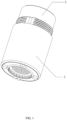
FIG. 1 illustrates a perspective view of an aerator inpreferred Embodiment 1 of the present disclosure; -
FIG. 2 illustrates an exploded perspective view of the aerator in preferredEmbodiment 1 of the present disclosure; -
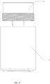
FIG. 3 illustrates a side view of the bubble in a water stop state inpreferred Embodiment 1 of the present disclosure; -
FIG. 4 illustrates a sectional view of the aerator in the water stop state inpreferred Embodiment 1 of the present disclosure; -
FIG. 5 illustrates a side view of the aerator in a water flowing state inpreferred Embodiment 1 of the present disclosure; -
FIG. 6 illustrates a sectional view of the aerator in the water flowing state inpreferred Embodiment 1 of the present disclosure; -
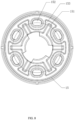
FIG. 7 illustrates a diagrammatic view of a water dividing body in preferredEmbodiment 1 of the present disclosure; -
FIG. 8 illustrates a top view of the water dividing body in preferredEmbodiment 1 of the present disclosure; -
FIG. 9 illustrates a diagrammatic view of a pressure cover inpreferred Embodiment 1 of the present disclosure; -
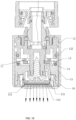
FIG. 10 illustrates a diagrammatic view of water outflow inpreferred Embodiment 1 of the present disclosure with the water dividing body in a first position; -
FIG. 11 illustrates a diagrammatic view of the water outflow inpreferred Embodiment 1 with the water dividing body in a second position; -
FIG. 12 illustrates a side view of an aerator in a water stop state inpreferred Embodiment 2 of the present disclosure; -
FIG. 13 illustrates a sectional view of the aerator in the water stop state inpreferred Embodiment 2 of the present disclosure; -
FIG. 14 illustrates a side view of the aerator in a water flowing state inpreferred Embodiment 2 of the present disclosure; -
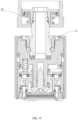
FIG. 15 illustrates a sectional view of the aerator in the water flowing state inEmbodiment 2 of the present disclosure; -
FIG. 16 illustrates an exploded perspective view of an aerator in preferredEmbodiment 3 of the present disclosure; -
FIG. 17 illustrates a sectional view of the aerator in a water stop state in preferredEmbodiment 3 of the present disclosure; -
FIG. 18 illustrates a sectional view of the aerator in a water flowing state in preferredEmbodiment 3 of the present disclosure; and -
FIG. 19 illustrates a sectional view of a shower body in a hovering state after swinging to an arbitrary position in preferredEmbodiment 3 of the present disclosure with the aerator in the water flowing state. - The technical solutions in the embodiments of the present disclosure will be described clearly and completely in combination with the accompanying drawings in the embodiments of the present disclosure; and it is obvious that the described embodiments are merely some embodiments of the present disclosure rather than all embodiments, and all other embodiments fall within the protective scope of the present disclosure provided that they are obtained based on the embodiments of the present disclosure by a person of ordinary skill in the art without creative works.
- In the description of the present disclosure, it should be noted that terms, such as "upper", "lower", "inner", "outer", "top/bottom", indicate orientations or positional relationships based on orientations or positional relationships shown in the accompanying drawings, are merely used to easily describe the present disclosure and simplify the description, rather than indicating or implying that a referenced device or element should have a particular orientation or be constructed and operated with a particular orientation, and therefore should not to be understood as a limitation of the present disclosure. Furthermore, the terms "first" and "second" are merely used for descriptive purposes and should not be understood as indicating or implying relative importance.
- In the description of the present disclosure, unless otherwise expressly specified and limited, it is noted that terms, such as "mounted", "disposed with", "socketed/sleeved", and "connected", should develop a broad understanding, for example, "connection" can be a wall-mountable connection, a detachable connection, an integrated connection, a mechanical connection, an electrical connection, a direct connection, an indirect connection via an intermediate medium, or a communication between inner portions of two elements, and the specific meaning of the terms in the present disclosure can be understood in specific conditions for those of ordinary skill in the art.
- Referring to
FIGS. 1-11 , this embodiment provides a telescopic aerator, which comprises: anaerator body 1, atelescopic assembly 2 and amounting seat 3; thetelescopic assembly 2 is swingably connected to theaerator body 1 through aball head 4; thetelescopic assembly 2 drives theaerator body 1 to move to a first position or a second position along an axial direction of themounting seat 3 under water pressure changes when the water stops and the water flows; when theaerator body 1 is in the first position, theaerator body 1 abuts themounting seat 3, and in this embodiment, a fixed ring connected to theball head 4 is accommodated in themounting seat 3 synchronously; and when theaerator body 1 is in the second position, theaerator body 1 is separated from themounting seat 3 by a preset distance, and thefixed ring 11 connected to theaerator body 1 and theball head 4 is exposed outside of themounting seat 3 synchronously. In this embodiment, theaerator body 1 is driven to move by the water pressure changes when the water stops and the water flows. As a simple alternative, an electrical signal can be generated by water flow changes when the water stops and the water flows, and a controller controls an electromagnetic unit or a mechanical unit to drive theaerator body 1 to move using electromagnetic force or mechanical force through the electrical signal. - The aforementioned aerator allows a piston component to drive the
aerator body 1 to move between the first position and the second position through the water pressure changes when the water stops the and the water flows, consequently, when the water flows, theaerator body 1 is separated from themounting seat 3 by the preset distance, so that theaerator body 1 can swing to adjust an angle of water outflow; and when the water stops, theaerator body 1 abuts themounting seat 3, ensuring consistency in an appearance of the aerator in a water stop state. - In order to enable the
aerator body 1 to be guided and restored to be centered when the water stops, themounting seat 3 and the aerator body comprise a guidingwall 31 configured for a guiding cooperation with the fixedring 11 within in the first position. Specifically, the guidingwall 31 surrounds to define areceiving chamber 32 with an opening at two ends, and thereceiving chamber 32 has a structure with a diameter of the opening that gradually increases from one end away from theaerator body 1 to the other end. In this way, theaerator body 1 will accurately restored to the second position through a guiding effect of the guidingwall 31 during a movement. - In order to be achieve the guiding cooperation with the guiding
wall 31, the fixedring 11 has an inclined surface that fits the guidingwall 31. - In addition, in order to ensure normal water outflow function of the aerator, the
telescopic assembly 2 and theball head 4 comprise awater flow passage 5 for water passage. In this way, water can flow into theaerator body 1 from the water flow passage. - In order to enable the
telescopic assembly 2 to move to different positions under different water pressures, thetelescopic assembly 2 comprises apiston 21 and aspring 22, thepiston 21 is movably disposed in the mountingseat 3, a side of thepiston 21 along an axial direction of the mountingseat 3 contacts the water flow, and the other side is connected to an inner wall of the mountingseat 3 through thespring 22. In this way, when thetelescopic assembly 2 drives an aerator assembly to the first position, thespring 22 is in a relatively loose state. When thetelescopic assembly 2 drives theaerator body 1 to the second position, thespring 22 is in a compressed state. At this time, if a water flowing state is converted to the water stop state, the water pressure applied to thepiston 21 becomes smaller, and thespring 22 releases an elastic restoring force to drive theaerator body 1 to be restored to the first position. - In this embodiment, the mounting
seat 3 comprises a through passage for thepiston 21 to pass through, the through passage comprises aside wall 35 extending upward along a direction of the water flow, and in this embodiment, theside wall 35 further comprises the guidingwall 31 disposed on a lower end of theside wall 35 and stretching outward along a radial direction; the mountingseat 3 further comprises an outerperipheral wall 32 configured for connecting to a water outlet device; and the outerperipheral wall 32 comprises a thread. The outerperipheral wall 32 is connected to a bottom of the guidingwall 31 through abottom wall 34, so that afirst groove 33 with an opening facing upward is formed between the outerperipheral wall 32 and the guidingwall 31, and thespring 22 abuts thebottom wall 34; and thepiston 21 comprises a sealingportion 211 hermetically sealed to the mountingseat 3 and a connectingportion 212 connected to theball head 4, and asecond groove 213 with an opening facing downward is formed between the sealingportion 211 and the connectingportion 212. Consequently, when theaerator body 1 is in the second position, theside wall 35 of the through passage is inserted into thesecond groove 213 through the opening. The sealingportion 211 comprises a groove disposed on an outer peripheral wall of the piston and a Y-shapedring 23 installed in the groove. The connectingportion 212 comprises a thread connected to theball head 4. - In this embodiment, in order to enable the
ball head 4 to be mounted, a side of thepiston 21 facing theball head 4 comprises a mounting hole configured for mounting theball head 4, and the mounting hole and theball head 4 are fixed by a threaded connection. - In addition, in order to prevent water leakage caused by the water flow flowing out of a gap between the
piston 21 and a side wall of the mountingseat 3, the Y-shapedring 23 is disposed between thepiston 21 and the side wall of the mountingseat 3. - In this embodiment, the
aerator body 1 can be switched between two different water outflow sprays, and a switching process can be achieved by rotating theaerator body 1. Therefore, an inner side of theaerator body 1 further comprises awater inlet seat 12, apressure cover 13, a sealinggasket 14 and awater dividing body 15, and thewater inlet seat 12 is disposed between theball head 4 and thewater dividing body 15, so that the water flowing out of thewater flow passage 5 can flow into thewater dividing body 15 through thewater inlet seat 12. Thewater dividing body 15 is fixedly connected to ashell 16 of theaerator body 1, anavoidance opening 131 is disposed on an axial center of thepressure cover 13 to enable a lower end of thewater inlet seat 12 to pass through, and the lower end of thewater inlet seat 12 passes through theavoidance opening 131 to be fixedly connected to thewater dividing body 15 by ascrew 121. Therefore, theshell 16 rotates to drive thewater dividing body 15 and thewater inlet seat 12 to rotate relative to the sealinggasket 14. - The sealing
gasket 14 is disposed between thepressure cover 13 and thewater dividing body 15, and a downward-pressingspring 17 is disposed on a side of thepressure cover 13 away from the sealinggasket 14, and one end of the spring away from thepressure cover 13 abuts thewater inlet seat 12. Thewater inlet seat 12 squeezes the downward-pressingspring 17 during a movement from a first position to a second position, so that the downward-pressingspring 17 drives thepressure cover 13 to downwardly press down the sealinggasket 14. - The pressure cover 13 further comprises an annular water passage opening 132 on an outer side of the
avoidance opening 131 along a radial direction. Thewater dividing body 15 comprises afirst flow passage 151 andsecond flow passages 152, thesecond flow passages 152 are disposed at intervals along a circumferential direction, and thefirst flow passage 151 is disposed between two adjacent ones of thesecond flow passages 152. Thefirst flow passage 151 and thesecond flow passages 152 are separated by abaffle 153. Thewater passage opening 132 is in communication with thefirst flow passage 151 and thesecond flow passages 152 simultaneously. - When the
water inlet seat 12 is in the first position, the downward-pressingspring 17 is in an extended state, a communication between thewater passage opening 132 and thesecond flow passages 152 is opened using the sealinggasket 14, the water flow respectively flows out through thefirst flow passage 151 and thesecond flow passages 152 of thewater dividing body 15, an outer annular water spray wraps an inner annular water spray to finally form a beam of the water flow at a water outlet nozzle of theaerator body 1, as inner and outer rings are filled with the water flow, external air cannot be inhaled into a cavity of theaerator body 1, water spray in a soft water state is formed. - When the
shell 16 drives thewater inlet seat 12 to rotate to the second position, the downward-pressingspring 17 is in a compressed state, and the sealinggasket 14 is squeezed by thepressure cover 13, thereby sealing the communication between thewater passage opening 132 and thesecond flow passages 152. Thesecond flow passages 152 of thewater dividing body 15 are sealed, and the water flows out of thefirst flow passage 151. Asteel sheet 154 is disposed on a water outlet of thefirst flow passage 151, and the water flows through fine holes on thesteel sheet 154 to form multiple beams of delicate steel sheet water sprays. - Referring to
FIGS. 12-15 , this embodiment differs fromEmbodiment 1 in that: the fixedring 11 inEmbodiment 1 is exposed on the side of theaerator body 1 facing the mountingseat 3, while in this embodiment, the fixedring 11 as a whole is accommodated in theaerator body 1; as the fixedring 11 is accommodated in theaerator body 1, the guidingwall 31 used to guide the fixedring 11 inEmbodiment 1 can also be excluded. Therefore, theside wall 35 in this embodiment does not comprise the guidingwall 31. The remainder aligns withEmbodiment 1 and will not be repeated herein. - Referring to
FIGS. 16-19 , this embodiment differs fromEmbodiment 1 in that: this embodiment comprises: anaerator body 10, atelescopic assembly 20 and a mountingseat 30; thetelescopic assembly 20 is disposed in theaerator body 10 and is swingably connected to the mountingseat 30 through aball head 40. That is: theball head 40 is inverted, and thetelescopic assembly 20 is disposed in theaerator body 10. - The
telescopic assembly 20 drives theaerator body 10 to move to the first position or the second position along an axial direction of the mountingseat 30 under the water pressure changes when the water stops and the water flows; when theaerator body 10 is in the first position, theaerator body 10 abuts the mountingseat 30; when theaerator body 10 is in the second position, theaerator body 10 is separated from the mountingseat 30 by the preset distance. In this embodiment, theaerator body 10 is driven to move by the water pressure changes when the water stops and the water flows. - The aforementioned aerator allows the
telescopic assembly 20 to drive theaerator body 10 to move between the first position and the second position through the water pressure changes when the water stops and the water flows, consequently, theaerator body 10 is separated from the mountingseat 30 by the preset distance when the water flows, so that theaerator body 10 can swing to adjust the angle of the water outflow; and when the water stops, theaerator body 10 abuts the mountingseat 30, ensuring the consistency in the appearance of the aerator in the water stop state. - In order to enable the
aerator body 10 to be guided and restored to be centralized when the water stops, in this embodiment, the mountingseat 30 is disposed with a fixedring 301, and theaerator body 10 is correspondingly disposed with a guidingwall 101 configured for a guiding cooperation with the fixedring 301. Specifically, the guidingwall 101 surrounds to define a receivingchamber 102 with an opening at two ends, and the receivingchamber 102 has a structure with a diameter of the opening that gradually increases from one end away from the mountingseat 30 to the other end. In this way, theaerator body 10 will be accurately restored to the second position through a guiding effect of the guidingwall 101 during the movement. - In addition, in order to ensure the normal water outflow function of the aerator, the
telescopic assembly 20 and theball head 40 are disposed with awater flow passage 50 configured for the water passage. In this way, the water can flow into theaerator body 10 from the water flow passage. - In order to enable the
telescopic assembly 20 to move to different positions under different water pressures, thetelescopic assembly 20 comprises apiston 201 and aspring 202, thepiston 201 is movably disposed in theaerator body 10, one side of thepiston 201 along an axial direction of theaerator body 10 contacts the water flow, in this embodiment, thetelescopic assembly 20 further comprises apiston cylinder 203, thepiston 201 is disposed in thepiston cylinder 203, thepiston cylinder 203 is assembled in theaerator body 10, and the other side of thepiston 201 is connected to an inner wall of theaerator body 10 through thepiston cylinder 203. - When the
telescopic assembly 20 drives the aerator assembly to be in the first position, thespring 202 is in a relatively loose state. When thetelescopic assembly 20 drives theaerator body 10 to be in the second position, thespring 202 is in a compressed state. At this time, if the water flowing state is converted to the water stop state, the water pressure applied to thepiston 201 becomes smaller, and thespring 202 releases an elastic restoring force to drive theaerator body 10 to be restored to the first position. - In this embodiment, the
ball head 40 comprises ahead 401 and arod 402. Thehead 401 is disposed in the mountingseat 30 and is hermetically sealed to an inner wall of the mountingseat 30 through asecond sealing ring 302. - The
piston 201 comprises a sealing portion 2011 hermetically sealed to thepiston cylinder 203 and a connectingportion 2012 connected to therod 402 of the ball head, and asecond groove 2013 with an opening facing upward is formed between the sealing portion 2011 and the connectingportion 2012. When theaerator body 10 is in the second position, aside wall 2031 of thepiston cylinder 203 is inserted into thesecond groove 2013 through the opening. The sealing portion 2011 comprises a groove disposed on an outer peripheral wall of the piston and a Y-shapedring 204 disposed in the groove. The connectingportion 2012 comprises a thread connected to therod 402 of the ball head. - In order to enable the aerator to be hovered within a swinging range in the water flowing state, this embodiment further comprises a damping
mechanism 60, the dampingmechanism 60 comprises afriction base 601, afriction cylinder pad 602 and asecond spring 603. Thesecond spring 603 is disposed in thehead 401 of the ball head, a lower end of thefriction cylinder pad 602 is disposed in thehead 401 and above thesecond spring 603, an upper end of thefriction cylinder pad 602 is a spherical annular surface, thefriction base 601 is disposed in the mountingseat 30, and a portion of an outer spherical surface of an upper portion of thehead 401 can form a clearance cooperation or an abutting cooperation with an inner wall of thefriction base 601. - Referring to
FIGS. 18 and19 , when the aerator swings to a preset position, the upper spherical annular surface of thefriction cylinder pad 602 abuts the inner wall of thefriction base 601 under an action of thesecond spring 603, and the aerator forms a hovered state. - The preceding description is merely preferred specific embodiments of the present disclosure, and the design and the concept of the disclosure of is not limited thereto, it is intended that the protective scope of the present disclosure cover non-substantive modifications of the present disclosure provided they are made based on the concept within the technical scope disclosed in the present disclosure by any person familiar with skill in the technical art.
- The present disclosure provides the telescopic aerator, the telescopic assembly drives the aerator body to move to a first position or a second position along an axial direction of the mounting seat when water stops and the water flows; when the aerator body is in the first position, the aerator body forms a positioning cooperation with the mounting seat along a swinging direction of the ball head; and when the aerator body is in the second position, the aerator body is separated from the mounting seat by a preset distance, so that the aerator body is released from the positioning cooperation with the mounting seat along the swinging direction of the ball head. The aerator can swing to adjust the water outflow direction when the water flows, and the consistency in the appearance of the aerator is also not damaged when the water stops.
Claims (18)
- A telescopic aerator, characterized in that, it comprises: an aerator body, a telescopic assembly and a mounting seat; the telescopic assembly is swingably connected to the aerator body through a ball head; and the telescopic assembly drives the aerator body to move to a first position or a second position along an axial direction of the mounting seat when water stops and the water flows; and
when the aerator body is in the second position, the aerator body is separated from the mounting seat by a preset distance. - The telescopic aerator according to claim 1, characterized in that: the aerator body is connected to the ball head through a fixed ring.
- The telescopic aerator according to claim 2, characterized in that: the fixed ring is exposed on a side of the aerator body facing the mounting seat.
- The telescopic aerator according to claim 1, characterized in that: the telescopic assembly comprises a sealing portion hermetically sealed to the mounting seat and a connecting portion connected to the ball head, a groove is disposed between the sealing portion and the connecting portion, and an opening of the groove faces downward.
- The telescopic aerator according to claim 4, characterized in that: the mounting seat comprises a through passage for the connecting portion to pass through, and when the aerator body is in the second position, a side wall of the through passage is inserted into the groove along the opening.
- The telescopic aerator according to claim 2, characterized in that: a guiding wall is disposed in the mounting seat, and the guiding wall guides the fixed ring during a movement of the aerator body from the second position to the first position.
- The telescopic aerator according to claim 6, characterized in that: the guiding wall surrounds to form a receiving chamber with an opening at two ends, and the receiving chamber comprises a structure with a diameter of the opening that gradually increases from one end away from the aerator body to the other end.
- The telescopic aerator according to claim 1, characterized in that: the telescopic assembly and the ball head comprise a water flow passage for water passage.
- The telescopic aerator according to any one of claims 1-8, characterized in that: the telescopic assembly comprises a piston and a spring, and the piston is movably disposed in the mounting seat, one side of the piston along an axial direction of the mounting seat contacts the water flow, and the other side is connected to an inner wall of the mounting seat through the spring.
- The telescopic aerator according to claim 9, characterized in that: a side of the piston facing the ball head comprises a mounting hole configured for mounting the ball head; and the mounting hole and the ball head are fixed by a threaded connection.
- A telescopic aerator, characterized in that, it comprises: an aerator body, a telescopic assembly and a mounting seat; the telescopic assembly is disposed in the aerator body and is swingably connected to the mounting seat through a ball head; and the telescopic assembly drives the aerator body to move to a first position or a second position along an axial direction of the mounting seat when water stops and the water flows; and
when the aerator body is in the second position, the aerator body is separated from the mounting seat by a preset distance. - The telescopic aerator according to claim 11, characterized in that: the mounting seat is connected to the aerator body through a fixed ring.
- The telescopic aerator according to claim 12, characterized in that: the fixed ring is exposed on a side of the mounting seat facing the aerator body.
- The telescopic aerator according to claim 11, characterized in that: the telescopic assembly comprises a sealing portion hermetically sealed to the mounting seat and a connecting portion connected to the ball head, a groove is disposed between the sealing portion and the connecting portion, and an opening of the groove faces upward.
- The telescopic aerator according to claim 12, characterized in that: the aerator body comprises a guiding wall, and the guiding wall guides the fixed ring during a movement of the aerator body from the second position to the first position.
- The telescopic aerator according to any one of claims 11-15, characterized in that: the telescopic assembly comprises a piston, a spring and a piston cylinder, the piston is movably disposed in the piston cylinder, one side of the piston along an axial direction of the aerator body contacts the water flow, and the other side is connected to an inner wall of the piston cylinder through the spring.
- The telescopic aerator according to claim 10, characterized in that: it further comprises a damping mechanism, which is disposed in the mounting seat and comprises a friction base, a friction cylinder pad and a second spring; it is used for the aerator to be hovered within a swinging range in a water flowing sate.
- The telescopic aerator according to claim 17, characterized in that: the second spring is disposed in the ball head, a lower end of the friction cylinder pad is disposed in a head and above the second spring, an upper end of the friction cylinder pad is a spherical annular surface, the friction base is disposed in the mounting seat, a portion of an outer spherical surface of an upper portion of the head forms a clearance cooperation or an abutting cooperation with an inner wall of the friction base; and
when the aerator swing to a preset position, the upper spherical annular surface of the friction cylinder pad abuts the inner wall of the friction base under an action of the second spring, and the aerator forms a hovered state.
Applications Claiming Priority (2)
| Application Number | Priority Date | Filing Date | Title |
|---|---|---|---|
| CN202221913174.3U CN218437337U (en) | 2022-07-22 | 2022-07-22 | A telescopic bubbler |
| PCT/CN2023/108871 WO2024017388A1 (en) | 2022-07-22 | 2023-07-24 | Telescopic bubbler |
Publications (2)
| Publication Number | Publication Date |
|---|---|
| EP4556642A1 true EP4556642A1 (en) | 2025-05-21 |
| EP4556642A4 EP4556642A4 (en) | 2025-11-26 |
Family
ID=85091198
Family Applications (1)
| Application Number | Title | Priority Date | Filing Date |
|---|---|---|---|
| EP23842450.1A Pending EP4556642A4 (en) | 2022-07-22 | 2023-07-24 | TELESCOPIC BUBBLER |
Country Status (3)
| Country | Link |
|---|---|
| EP (1) | EP4556642A4 (en) |
| CN (1) | CN218437337U (en) |
| WO (1) | WO2024017388A1 (en) |
Families Citing this family (1)
| Publication number | Priority date | Publication date | Assignee | Title |
|---|---|---|---|---|
| CN218437337U (en) * | 2022-07-22 | 2023-02-03 | 厦门松霖科技股份有限公司 | A telescopic bubbler |
Family Cites Families (10)
| Publication number | Priority date | Publication date | Assignee | Title |
|---|---|---|---|---|
| US4244526A (en) * | 1978-08-16 | 1981-01-13 | Arth Michael J | Flow controlled shower head |
| DE202006010072U1 (en) * | 2006-06-28 | 2006-09-07 | Zhou, Huasong, Xiamen | Automatic protruding and retracting kitchen water emitter has connecting part, provided at main part from above, which connects itself firmly with outer end of soft hose whereby guide hose is provided in the middle of main part |
| US7581685B2 (en) * | 2007-07-19 | 2009-09-01 | Christian Belisle | Faucet end piece |
| CN201567624U (en) * | 2009-10-15 | 2010-09-01 | 尼亚加拉节能产品(厦门)有限公司 | Two-function bubbler with separable body and adjustable flow rate |
| US9447567B2 (en) * | 2014-03-08 | 2016-09-20 | So-Mei Huang | Flow adjustable bubble aerator |
| CN215519011U (en) * | 2021-08-30 | 2022-01-14 | 厦门市智慧宸星科技有限公司 | Telescopic bubbler and faucet |
| CN216810122U (en) * | 2022-01-20 | 2022-06-24 | 广东顶尖管业科技有限公司 | Bubbler and faucet |
| CN218060566U (en) * | 2022-05-24 | 2022-12-16 | 厦门松霖科技股份有限公司 | A multifunctional bubbler and water outlet device |
| CN218437337U (en) * | 2022-07-22 | 2023-02-03 | 厦门松霖科技股份有限公司 | A telescopic bubbler |
| CN116290238A (en) * | 2023-04-12 | 2023-06-23 | 箭牌家居集团股份有限公司 | Bubbler and water outlet device |
-
2022
- 2022-07-22 CN CN202221913174.3U patent/CN218437337U/en active Active
-
2023
- 2023-07-24 EP EP23842450.1A patent/EP4556642A4/en active Pending
- 2023-07-24 WO PCT/CN2023/108871 patent/WO2024017388A1/en not_active Ceased
Also Published As
| Publication number | Publication date |
|---|---|
| CN218437337U (en) | 2023-02-03 |
| WO2024017388A1 (en) | 2024-01-25 |
| EP4556642A4 (en) | 2025-11-26 |
Similar Documents
| Publication | Publication Date | Title |
|---|---|---|
| US11014115B2 (en) | Showerhead capable of discharging residual water | |
| EP3366377B1 (en) | An outlet device capable of switching different outlet water types in a same outlet hole | |
| US20190001350A1 (en) | Flow control component and shower | |
| CN209041572U (en) | Outlet switching device | |
| US10744522B2 (en) | Flow rate controller | |
| CN206911592U (en) | Automatic Regulation gondola water faucet | |
| US6363961B1 (en) | Massage bath tub faucet structure | |
| CN216221278U (en) | Shower system | |
| CN211887471U (en) | Self-adaptive pressure shower head | |
| US7188641B2 (en) | Water valve assembly for bathroom faucets | |
| JP7220762B2 (en) | Water discharge device and shower head | |
| WO2024017388A1 (en) | Telescopic bubbler | |
| CN112827691A (en) | A spray gun with switchable fluid shape | |
| CN218718981U (en) | Water outlet device | |
| JP2001304453A (en) | Valve element for simultaneously opening valve system | |
| EP3744431A1 (en) | Shower head capable of switching water spray | |
| CN216158354U (en) | Water outlet faucet | |
| JP2000319961A (en) | Flow control valve and shower head | |
| JPS62163122A (en) | Pressure reducing valve | |
| US12534890B1 (en) | Waterway switching apparatus with magnetic function | |
| US20200406276A1 (en) | Anti-splash water outflow device | |
| CN213468265U (en) | Flow regulating mechanism of shower head | |
| CN113738909A (en) | Water outlet faucet | |
| CN220559533U (en) | Adjustable shower head | |
| CN218796602U (en) | A quick-discharging shower head for residual water |
Legal Events
| Date | Code | Title | Description |
|---|---|---|---|
| STAA | Information on the status of an ep patent application or granted ep patent |
Free format text: STATUS: THE INTERNATIONAL PUBLICATION HAS BEEN MADE |
|
| PUAI | Public reference made under article 153(3) epc to a published international application that has entered the european phase |
Free format text: ORIGINAL CODE: 0009012 |
|
| STAA | Information on the status of an ep patent application or granted ep patent |
Free format text: STATUS: REQUEST FOR EXAMINATION WAS MADE |
|
| 17P | Request for examination filed |
Effective date: 20250212 |
|
| AK | Designated contracting states |
Kind code of ref document: A1 Designated state(s): AL AT BE BG CH CY CZ DE DK EE ES FI FR GB GR HR HU IE IS IT LI LT LU LV MC ME MK MT NL NO PL PT RO RS SE SI SK SM TR |
|
| DAV | Request for validation of the european patent (deleted) | ||
| DAX | Request for extension of the european patent (deleted) | ||
| STAA | Information on the status of an ep patent application or granted ep patent |
Free format text: STATUS: EXAMINATION IS IN PROGRESS |
|
| A4 | Supplementary search report drawn up and despatched |
Effective date: 20251023 |
|
| RIC1 | Information provided on ipc code assigned before grant |
Ipc: E03C 1/08 20060101AFI20251020BHEP Ipc: B05B 1/16 20060101ALI20251020BHEP Ipc: B05B 15/654 20180101ALI20251020BHEP |
|
| 17Q | First examination report despatched |
Effective date: 20251104 |