EP4556619A1 - Clothes treatment apparatus - Google Patents
Clothes treatment apparatus Download PDFInfo
- Publication number
- EP4556619A1 EP4556619A1 EP23852791.5A EP23852791A EP4556619A1 EP 4556619 A1 EP4556619 A1 EP 4556619A1 EP 23852791 A EP23852791 A EP 23852791A EP 4556619 A1 EP4556619 A1 EP 4556619A1
- Authority
- EP
- European Patent Office
- Prior art keywords
- dehumidification
- treatment apparatus
- kit
- clothes treatment
- air
- Prior art date
- Legal status (The legal status is an assumption and is not a legal conclusion. Google has not performed a legal analysis and makes no representation as to the accuracy of the status listed.)
- Pending
Links
Images





Classifications
-
- D—TEXTILES; PAPER
- D06—TREATMENT OF TEXTILES OR THE LIKE; LAUNDERING; FLEXIBLE MATERIALS NOT OTHERWISE PROVIDED FOR
- D06F—LAUNDERING, DRYING, IRONING, PRESSING OR FOLDING TEXTILE ARTICLES
- D06F58/00—Domestic laundry dryers
- D06F58/32—Control of operations performed in domestic laundry dryers
- D06F58/34—Control of operations performed in domestic laundry dryers characterised by the purpose or target of the control
-
- D—TEXTILES; PAPER
- D06—TREATMENT OF TEXTILES OR THE LIKE; LAUNDERING; FLEXIBLE MATERIALS NOT OTHERWISE PROVIDED FOR
- D06F—LAUNDERING, DRYING, IRONING, PRESSING OR FOLDING TEXTILE ARTICLES
- D06F58/00—Domestic laundry dryers
- D06F58/32—Control of operations performed in domestic laundry dryers
- D06F58/34—Control of operations performed in domestic laundry dryers characterised by the purpose or target of the control
- D06F58/36—Control of operational steps, e.g. for optimisation or improvement of operational steps depending on the condition of the laundry
- D06F58/38—Control of operational steps, e.g. for optimisation or improvement of operational steps depending on the condition of the laundry of drying, e.g. to achieve the target humidity
-
- D—TEXTILES; PAPER
- D06—TREATMENT OF TEXTILES OR THE LIKE; LAUNDERING; FLEXIBLE MATERIALS NOT OTHERWISE PROVIDED FOR
- D06F—LAUNDERING, DRYING, IRONING, PRESSING OR FOLDING TEXTILE ARTICLES
- D06F58/00—Domestic laundry dryers
- D06F58/20—General details of domestic laundry dryers
-
- D—TEXTILES; PAPER
- D06—TREATMENT OF TEXTILES OR THE LIKE; LAUNDERING; FLEXIBLE MATERIALS NOT OTHERWISE PROVIDED FOR
- D06F—LAUNDERING, DRYING, IRONING, PRESSING OR FOLDING TEXTILE ARTICLES
- D06F58/00—Domestic laundry dryers
- D06F58/20—General details of domestic laundry dryers
- D06F58/22—Lint collecting arrangements
-
- D—TEXTILES; PAPER
- D06—TREATMENT OF TEXTILES OR THE LIKE; LAUNDERING; FLEXIBLE MATERIALS NOT OTHERWISE PROVIDED FOR
- D06F—LAUNDERING, DRYING, IRONING, PRESSING OR FOLDING TEXTILE ARTICLES
- D06F58/00—Domestic laundry dryers
- D06F58/20—General details of domestic laundry dryers
- D06F58/24—Condensing arrangements
-
- D—TEXTILES; PAPER
- D06—TREATMENT OF TEXTILES OR THE LIKE; LAUNDERING; FLEXIBLE MATERIALS NOT OTHERWISE PROVIDED FOR
- D06F—LAUNDERING, DRYING, IRONING, PRESSING OR FOLDING TEXTILE ARTICLES
- D06F2103/00—Parameters monitored or detected for the control of domestic laundry washing machines, washer-dryers or laundry dryers
-
- D—TEXTILES; PAPER
- D06—TREATMENT OF TEXTILES OR THE LIKE; LAUNDERING; FLEXIBLE MATERIALS NOT OTHERWISE PROVIDED FOR
- D06F—LAUNDERING, DRYING, IRONING, PRESSING OR FOLDING TEXTILE ARTICLES
- D06F2103/00—Parameters monitored or detected for the control of domestic laundry washing machines, washer-dryers or laundry dryers
- D06F2103/40—Opening or locking status of doors
-
- D—TEXTILES; PAPER
- D06—TREATMENT OF TEXTILES OR THE LIKE; LAUNDERING; FLEXIBLE MATERIALS NOT OTHERWISE PROVIDED FOR
- D06F—LAUNDERING, DRYING, IRONING, PRESSING OR FOLDING TEXTILE ARTICLES
- D06F2105/00—Systems or parameters controlled or affected by the control systems of washing machines, washer-dryers or laundry dryers
- D06F2105/32—Air flow control means
-
- D—TEXTILES; PAPER
- D06—TREATMENT OF TEXTILES OR THE LIKE; LAUNDERING; FLEXIBLE MATERIALS NOT OTHERWISE PROVIDED FOR
- D06F—LAUNDERING, DRYING, IRONING, PRESSING OR FOLDING TEXTILE ARTICLES
- D06F2105/00—Systems or parameters controlled or affected by the control systems of washing machines, washer-dryers or laundry dryers
- D06F2105/46—Drum speed; Actuation of motors, e.g. starting or interrupting
-
- D—TEXTILES; PAPER
- D06—TREATMENT OF TEXTILES OR THE LIKE; LAUNDERING; FLEXIBLE MATERIALS NOT OTHERWISE PROVIDED FOR
- D06F—LAUNDERING, DRYING, IRONING, PRESSING OR FOLDING TEXTILE ARTICLES
- D06F2105/00—Systems or parameters controlled or affected by the control systems of washing machines, washer-dryers or laundry dryers
- D06F2105/54—Changing between normal operation mode and special operation modes, e.g. service mode, component cleaning mode or stand-by mode
-
- D—TEXTILES; PAPER
- D06—TREATMENT OF TEXTILES OR THE LIKE; LAUNDERING; FLEXIBLE MATERIALS NOT OTHERWISE PROVIDED FOR
- D06F—LAUNDERING, DRYING, IRONING, PRESSING OR FOLDING TEXTILE ARTICLES
- D06F58/00—Domestic laundry dryers
- D06F58/02—Domestic laundry dryers having dryer drums rotating about a horizontal axis
-
- D—TEXTILES; PAPER
- D06—TREATMENT OF TEXTILES OR THE LIKE; LAUNDERING; FLEXIBLE MATERIALS NOT OTHERWISE PROVIDED FOR
- D06F—LAUNDERING, DRYING, IRONING, PRESSING OR FOLDING TEXTILE ARTICLES
- D06F58/00—Domestic laundry dryers
- D06F58/20—General details of domestic laundry dryers
- D06F58/206—Heat pump arrangements
Definitions
- the present disclosure relates to a clothes treatment apparatus and, more particularly, to a clothes treatment apparatus capable of drying clothing or bedding accommodated therein, as well as having a drying function for an external space.
- a clothes treatment apparatus is any device for managing or processing clothing, such as washing, drying, or removing wrinkles from clothing or bedding, either in the home or at a place such as a laundry shop.
- Clothes treatment apparatuses include a washer, a dryer, a washer and dryer combo, etc.
- the dryer supplies hot air to an object to be processed, such as clothing or bedding, which is fed into a drum (or a tub), to evaporate the moisture contained in the object to be processed.
- an object to be processed such as clothing or bedding
- a drum or a tub
- the air which evaporates the moisture from the object to be processed in the drum and exits the drum, absorbs the moisture from the object to be processed and becomes hot and humid.
- This hot and humid air from which the moisture is removed on a circulation channel provided in the dryer, is heated, and then reintroduced to a drum.
- Korean Public Patent No. 10-2019-0128464 discloses a clothes treatment apparatus.
- the prior art discloses a drum for accommodating clothing, a circulation channel forming a path along which air discharged from the front opening of the drum is introduced into the rear opening of the drum after exchanging heat, and a base cabinet disposed below the drum to provide a space in which various components are mounted.
- the clothes treatment apparatus of the prior art is configured to dry clothing or bedding accommodated in the drum, but does not specifically consider a drying function for an external space in which the clothes treatment apparatus is installed.
- a clothes treatment apparatus for drying clothing or bedding accommodated therein faces the challenge of appropriately implementing a drying function for an external space as well.
- conventional clothes treatment apparatuses are limited in that the conventional clothes treatment apparatuses cannot adequately solve this challenge.
- An aspect of the present disclosure is to solve the above problems with the clothes treatment apparatuses.
- an aspect of the present disclosure is to enable a clothes treatment apparatus, which dries clothing or bedding accommodated therein, to also implement a dehumidification function for an external space as needed.
- an aspect of the present disclosure is to enable the dehumidification function to be more efficiently performed during the dehumidification of the external space using the clothes treatment apparatus.
- an aspect of the present disclosure is to make it easier and simpler to switch the state of the clothes treatment apparatus when dehumidification of the external space is needed.
- an aspect of the present disclosure is to easily determine whether dehumidification of the external space is needed, thereby ensuring that the clothes treatment apparatus always operates with optimal control.
- a clothes treatment apparatus configured such that a dehumidification function for an external space can be implemented by installing a dehumidification kit as needed.
- the clothes treatment apparatus is configured such that air is introduced from an external space into a circulation channel through a dehumidification kit installed in an introduction opening, is dehumidified, and is then discharged back into the external space.
- the clothes treatment apparatus is configured to optimize an air movement path during dehumidification of an external space to improve dehumidification efficiency.
- the clothes treatment apparatus is configured such that movement paths for air discharged from a drum through the introduction opening and air introduced into a suction duct through the introduction opening by the dehumidification kit are separated from each other.
- the clothes treatment apparatus is configured to make installation of the dehumidification kit easier and simpler.
- the clothes treatment apparatus is configured such that the dehumidification kit is detachably installed on the top surface of a filter part installed between the introduction opening and the suction duct.
- the dehumidification kit may include a first body part and a second body part.
- the first body part may be formed to protrude relatively more than the second body part.
- the clothes treatment apparatus may hold a door in an open state via a holder part of the dehumidification kit.
- the holder part and the door may be attached to each other by magnetic force.
- the door may be held to maintain an opening angle of 20° during dehumidification of the external space.
- an installation surface of the dehumidification kit may be formed to correspond to a curved shape of the introduction opening.
- an inner rib may protrude from the installation surface of the dehumidification kit.
- a handle may be formed on the top surface of the dehumidification kit.
- a contact terminal may be formed on the dehumidification kit to be electrically connected to a cabinet when the dehumidification kit is installed.
- the contact terminal of the dehumidification kit may be electrically connected to multiple points on the cabinet.
- the contact terminal of the dehumidification kit may be elastically deformable.
- the clothes treatment apparatus is configured to determine when dehumidification of the external space is needed and to optimally control the same.
- a control part is configured to control the operation of the drum and a circulation fan in consideration of whether the dehumidification kit is installed.
- the clothes treatment apparatus may determine whether the dehumidification kit is installed, based on a change in a resistance value depending on whether the contact terminal formed on the dehumidification kit is in contact with an electrode sensor installed in the cabinet.
- control part may be configured to stop the operation of the drum when the dehumidification kit is installed.
- control part may be configured to reduce a load on the circulation fan when the dehumidification kit is installed.
- control part may be configured to unlock the door when the dehumidification kit is installed.
- a center portion of the contact terminal may be formed to protrude while both ends of the contact terminal are fixed.
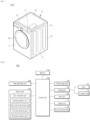
- FIG. 1 is a perspective view of a clothes treatment apparatus according to one embodiment of the present disclosure.
- FIG. 2 illustrate the main components of a clothes treatment apparatus according to one embodiment of the present disclosure.
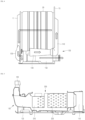
- FIGS. 3 and 4 schematically illustrate the circulation of air in a clothes treatment apparatus according to one embodiment of the present disclosure.
- the clothes treatment apparatus is an apparatus for processing laundry (or, objects to be dried) such as clothing introduced into a drum, and is not limited to a dryer, but may also be a washer or a washer and dryer combo.
- a clothes treatment apparatus 1000 includes a cabinet 10, a drum 30 which is disposed in the cabinet 10 and in which laundry is accommodated and rotated, and a driving part 106 configured to rotate the drum 30, a heat exchange part 200 configured to heat air circulating in the drum 30 to dry the laundry and heat the circulating air, a circulation fan 110 configured to circulate the air in the drum 30, a suction duct 120 configured to suction the circulating air from the drum 30, and a circulation channel 130 configured to guide the flow of the air.
- the cabinet 10 forms the exterior of the clothes treatment apparatus 1000 and provides a space in which the drum 30 and other components are disposed.
- the cabinet 10 may be formed in an overall rectangular prism shape.
- the cabinet 10 has a door 20 disposed at the front thereof, and the door 20 is hinge-rotated about one end thereof to open and close the inside of the cabinet 10.
- the cabinet 10 may include a front cover 11, a top plate 16, side covers 12 and 13, a rear cover 15, and a base 14.
- the front cover 11 has an introduction opening 18 and a door 20 configured to open and close the introduction opening 18.
- the introduction opening 18 may communicate with the drum 30.
- a control panel 17 may be disposed on the upper portion of the front cover 11.
- the control panel 17 may include a display (e.g., LCD, LED panel, etc.) for displaying the operating state of the clothes treatment apparatus 1000, an input part 800 (e.g., a button, a dial, a touch screen, etc.) configured to receive operation commands for the clothes treatment apparatus 1000 from a user, and an output part 175 configured to output voice guidance or sound effects or warning sounds regarding the operating state.
- a display e.g., LCD, LED panel, etc.
- an input part 800 e.g., a button, a dial, a touch screen, etc.
- an output part 175 configured to output voice guidance or sound effects or warning sounds regarding the operating state.
- the input part 800 includes an input means such as at least one button, switch, or touchpad installed on the control panel 17.
- the input part 800 inputs operation settings, including power input, operation mode, and laundry type settings. When the type of laundry is selected and a power key is input, the input part 800 inputs data about the operation settings into the control part 600.
- the output part 175 includes a display for displaying information about the operation settings, input by the input part 800, and outputting the operating state of the clothes treatment apparatus 1000, and includes a speaker or a buzzer for outputting voice guidance, predetermined sound effects, or warning sounds.
- the display may include a menu screen for operation settings and operation control of the clothes treatment apparatus 1000, and may output a guidance message or a warning including a combination of at least one among letters, numbers, and images for the operation settings or the operating state.
- the memory 104 stores control data for controlling the operation of the clothes treatment apparatus 1000, input operation setting data, data regarding an operation mode, and reference data for determining errors in the clothes treatment apparatus 1000.
- the memory 104 stores data that is detected or measured during operation of the clothes treatment apparatus 1000, and data that is transmitted or received via a communication part 190.
- the memory 104 may be a storage device such as ROM, RAM, EPROM, flash drive, or hard drive.
- the communication part 190 transmits and receives data in a wired or wireless manner.
- the communication part 190 may be connected to a network formed within a building or a predetermined distance, such as a home network, to transmit and receive data, may also be connected to an external server, such as the Internet, and may communicate with a terminal having a control function.
- the communication part 190 transmits the operation state or the drying progress state of the clothes treatment apparatus 1000, and receives a command for the clothes treatment apparatus 1000.
- the communication part 190 may include a communication module for Wi-Fi or WiBro in addition to a short-range wireless communication such as Zigbee or Bluetooth, to transmit and receive data.
- a power supply part 105 converts supplied commercial power to provide operation power.
- the power supply part 105 blocks overcurrent, rectifies and smooths the supplied power, and supplies operation power having a predetermined magnitude.
- the drum 30 is cylindrically formed and has an open front surface and an open rear surface, wherein the front surface communicates with the introduction opening 18. Furthermore, an inlet is formed on the rear surface of the drum 30 so that air is introduced therethrough, and the inlet is connected with an inlet duct 140 for air circulation. Furthermore, the inlet duct 140 is connected to the circulation channel 130.
- the driving part 106 includes a motor that is fixed to the base 14 of the cabinet 10.
- the motor provides power to rotate the drum 30 and is also connected to the circulation fan 110 to rotate the circulation fan 110.
- the circulation fan 110 By rotation of the circulation fan 110, air in the drum 30 may be introduced into the suction duct 120.
- the suction duct 120 is connected to the circulation channel 130.
- the air discharged from the drum 30 is guided into the suction duct 120, passes through a heat exchanger through the circulation channel 130, and is reintroduced into the drum 30 through the inlet duct 140, thereby circulating the air.
- the circulation channel 130 passing through the drum 30 may be variously formed.
- the circulation channel 130 may be connected to the drum 30 to form a closed loop for air circulation.
- a part of air may be configured to be discharged to the outside via an exhaust duct 150 as needed.
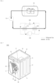
- FIG. 5 illustrates, in more detail, an air circulation part and a heat exchange part in a clothes treatment apparatus according to one embodiment of the present disclosure.
- FIG. 6 schematically illustrating the circulation of refrigerant in a heat exchange part in a clothes treatment apparatus according to one embodiment of the present disclosure.
- An air circulation part 100 is a part that guides air discharged from the drum 30 to reintroduce the air into the drum 30, and includes the suction duct 120, the circulation channel 130, the inlet duct 140, and the circulation fan 110 described above.
- the heat exchange part 200 is a part installed in the circulation channel 130 of the air circulation part 100 to exchange heat with air, and circulates a refrigerant and operate in a heat pump cycle.
- Laundry accommodated in the drum 30 is dried by heated air supplied into the drum 30.
- Air discharged from the drum 30 contains moisture evaporated from the laundry during the drying process, is introduced into the circulation channel 130, is heated by the heat exchange part 200, and is then supplied back to the drum 30.
- the heat exchange part 200 includes a compressor 230, an evaporator 210, a condenser 220, and an expansion valve 240.
- the compressor 230, the evaporator 210, and the condenser 220 are connected to each other through a refrigerant pipe, and a refrigerant is circulated.
- air heated by heat exchange between a refrigerant and air in the condenser 220 and the evaporator 210 is supplied to the drum 30.
- the heat exchange part 200 may also perform heat exchange through a medium other than a refrigerant as needed.
- the evaporator 210 exchanges heat between the air, which is introduced into the circulation channel 130 from the drum 30 through the suction duct 120, and the refrigerant, thereby recovering the amount of heat of the air passing through the circulation channel 130. Furthermore, the evaporator 210 condenses the moisture contained in the air passing through the circulation channel 130.
- the condenser 220 exchanges heat between the refrigerant and the air that has passed through the evaporator 210 and reintroduces the heated air back into the drum 30 via the inlet duct 140.
- the low-temperature low-humidity air that has passed through the evaporator 210 is introduced into the condenser 220 and is changed to a high-temperature low-humidity state by exchanging heat with the refrigerant.
- the refrigerant discharged from the condenser 220 passes through the evaporator 210 and is returned to the compressor 230.
- the compressor 230 compresses the evaporated refrigerant and discharges the compressed refrigerant to the condenser 220, and the expansion valve 240 expands, in the evaporator 210, the refrigerant condensed in the condenser 220.
- High-temperature high-humidity air discharged from the drum 30 has a higher temperature than the refrigerant in the evaporator 210. Therefore, as the air passes through the evaporator 210, the air exchanges heat with the refrigerant and condensed and cooled. As a result, the high-temperature high-humidity air is dehumidified and cooled by the evaporator 210. Condensed water generated during the air condensation process may be collected in a separate condensed-water housing and drained.
- Air is circulated by the circulation fan 110.
- the air passes through the drum 30 and is introduced into the evaporator 210 by the circulation fan 110, is condensed in the evaporator 210, and is introduced into the condenser 220 in a low-temperature low-humidity state.
- the air is heated by exchanging heat with a refrigerant in the condenser 220 and is then reintroduced into the drum 30. In this way, the air moves in the order of the drum 30, the evaporator 210, and the condenser 220.
- a refrigerant is discharged to the condenser 220 at a high temperature and high pressure by the compressor 230, and after exchanging heat with the air in the condenser 220, is introduced into the evaporator 210 and evaporated.
- the expansion valve 240 is installed between the condenser 220 and the evaporator 210.
- the expansion valve 240 expands a low-temperature high-pressure condensed refrigerant and delivers the expanded refrigerant to the evaporator 210.
- the expanded refrigerant is evaporated in the evaporator 210, is introduced into the compressor 230 in a low-temperature and low-pressure state, and is then discharged to the condenser 220 in a high-temperature and high-pressure state.
- the expansion valve 240 may be an electronic expansion valve (EEV).
- EEV electronic expansion valve
- a control part 600 stores the operation settings input from an input part 800 in a memory 140, processes data transmitted and received via the communication part 190, and controls the operation settings and operating state of the clothes treatment apparatus 1000 to be output via the output part 175.
- the control part 600 may control the communication part 190 to transmit data of the clothes treatment apparatus 1000 to the terminal.
- the control part 600 may control the operation of the drum 30 and the circulation fan 110 via the driving part 160, based on the operation settings input from the input part 800, and may variably control the operation according to the detection value of a specific sensor.
- the control part 600 may control the heat exchange part 200 during operation to heat circulating air, and may control the temperature of air supplied to the drum 30.
- control part 600 may control the operation of the air circulation part 100 and the heat exchange part 200.
- the operation of the air circulation part 100 and the heat exchange part 200 may include whether the air circulation part 100 and the heat exchange part 200 are turned on or off, the operation time, the operation state, and the like.
- the clothes treatment apparatus 1000 having the above structure may dry clothing or bedding accommodated therein by using high-temperature dry air.
- a configuration for drying an external space by the clothes treatment apparatus 1000 may be additionally required in terms of the emergence of multifunctionality that can conveniently make a comfortable space by removing moisture in the space in which the clothes treatment apparatus 1000 is installed through the clothes treatment apparatus 1000 without a separate device.
- FIG. 7 exemplarily illustrates a state in which dehumidification of an external space is performed by a clothes treatment apparatus according to one embodiment of the present disclosure.
- FIG. 8 is an exploded perspective view illustrating, in more detail, a portion in FIG. 7 where a dehumidification kit is installed.
- FIG. 9 schematically illustrates air circulation in FIG. 7 .
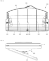
- FIGS. 10 to 12 illustrate the dehumidification kit in FIG. 7 in more detail.
- FIG. 13 exemplarily illustrates the holding state of a door in FIG. 7 .
- FIGS. 14 and 15 illustrate, in more detail, a portion where a filter part is coupled to the dehumidification kit in FIG. 7 .
- FIGS. 16 and 17 illustrate a contact terminal of the dehumidification kit and an electrode sensor of a cabinet in FIG. 7 .
- a clothes treatment apparatus 1000 may include a drum 30, a suction duct 120, a circulation channel 130, an inlet duct 140, a circulation fan 110, a heat exchange part 200, a door 20, and a dehumidification kit 900.
- the drum 30 may be a part which is installed within a cabinet 10 and has a front surface facing an introduction opening 18 of the cabinet 10. Air accommodated in the drum 30 may be discharged to an external space through the introduction opening 18.
- the suction duct 120 is a part which is disposed below the front surface of the drum 30 and into which air is introduced. Air in the external space may be introduced into the suction duct 120 through the introduction opening 18.
- the circulation channel 130 is a part connected to the suction duct 120 to guide the flow of air, and the air introduced into the suction duct 120 may be dehumidified while moving along the circulation channel 130.
- the circulation fan 110 may be a part which forms the flow of air between the suction duct 120 and the inlet duct 140, and may apply pressure to move the air along the circulation channel 130.
- the heat exchange part 200 is a part installed in the circulation channel 130 to exchange heat with the air, and the air passing through the heat exchange part 200 may exchange heat to be dehumidified.
- the door 20 may be a part installed on the cabinet 10 to open and close the introduction opening 18. External air may be introduced into the suction duct 120 through the introduction opening 18 while the door 20 is open.
- the dehumidification kit 900 may be a part that is installed on the introduction opening 18, while the door 20 is open, to separate movement paths for air discharged from the drum 30 through the introduction opening 18 and air introduced into the suction duct 120 through the introduction opening 18.
- humid air in an external space may be introduced into the suction duct 120 via the dehumidification kit 900 installed at the introduction opening 18.
- Air humidified while moving along the circulation channel 130 in the clothes treatment apparatus 1000 may be prevented from being introduced into the suction duct 120 again by the dehumidification kit 900.
- the dehumidified air may be immediately discharged to the external space through the introduction opening 18, and the humid air in the external space may be continuously introduced into the suction duct 120.
- the humid air in the external space of the clothes treatment apparatus 1000 may be introduced into the suction duct 120 through the introduction opening 18, be forcedly sent by the circulation fan 110 along the circulation channel 130, be dehumidified by the heat exchange part 200, and be discharged back into the external space through the drum 30 via the introduction opening 18.
- humid air in the external space may be dehumidified while passing through the clothes treatment apparatus 1000, and thus, a dehumidification function for the external space in which the clothes treatment apparatus 1000 is installed may be realized.
- air in an external space is introduced into the circulation channel 130 through the dehumidification kit 900 installed in the introduction opening 18, dehumidified, and then discharged back into the external space.
- a dehumidification function for the external space in which the clothes treatment apparatus 1000 is installed may be implemented as needed.
- the dehumidification kit 900 separates movement paths for air discharged from the drum 30 through the introduction opening 18 and air introduced into the suction duct 120 through the introduction opening 18, so that the air before dehumidification and the air after dehumidification do not mix with each other, thereby improving the efficiency of dehumidification of the external space.
- the clothes treatment apparatus 1000 may further include a filter part 300 installed between the introduction opening 18 and the suction duct 120 to capture foreign matter in the air.
- the dehumidification kit 900 may be detachably installed to cover the top surface of the filter part 300.
- foreign matter such as a large amount of lint
- contamination may be caused by the foreign matter introduced into the circulation channel 130, and there is a risk that mold or bacteria may grow, especially in a humid and contaminated environment.
- the filter part 300 may include multiple filters.
- the filter part 300 may be arranged such that an inner filter 302 is inserted into an outer filter 301, and the outer filter 301 is inserted into a filter guide 121 and passes through a communication hole.
- a duct connector 122 may be mounted to a front cover 11 and connected to the filter guide 121.
- the duct connector 122 may be mounted on the front surface of the front cover 11.
- the lower end of the filter guide 121 may be accommodated in the duct connector 122.
- the dehumidification kit 900 may be installed on the top surface of the filter part 300. Accordingly, the dehumidification kit 900 may be installed without the use of a separate fastener, and on the top surface of the filter part 300, may separate movement paths for air discharged from the drum 30 and air introduced into the suction duct 120 through the introduction opening 18.
- the dehumidification kit 900 is detachably installed on the filter part 300, thereby making it easier for a user to dry clothing accommodated in the drum 30 or dehumidify an external space.
- the dehumidification kit 900 is detachably installed on the top surface of the filter part 300 installed between the introduction opening 18 and the suction duct 120, making it easier and simpler to install and use the dehumidification kit 900 as needed.
- the dehumidification kit 900 may include a first body part 910 protruding toward the front side of the introduction opening 18 and a second body part 920 protruding toward the rear side of the introduction opening 18 to cover the top surface of the filter part 300.
- the first body part 910 protrudes toward the front side of the introduction opening 18 so that air in an external space may be introduced into the lower portion of the first body part 910.
- the second body part 920 protrudes toward the rear side of the introduction opening 18, so that the air introduced into the lower portion of the first body part 910 may be introduced into the top surface of the filter part 300 covered by the second body part 920.
- the dehumidification kit 900 includes the first body part 910 and the second body part 920, thereby smoothly moving air introduced from the rear side of the introduction opening 18 to the suction duct 120 after introducing external air from the front side of the introduction opening 18.
- the first body part 910 may be formed with a protrusion length that is relatively longer than that of the second body part 920.
- the first body part 910 may protrude relatively more to allow air in the external space to be more easily introduced into the dehumidification kit 900.
- the second body part 920 may protrude relatively less, thereby minimizing the introduction of air dehumidified and then accommodated in the drum 30 into the second body part 920, that is, minimizing collision of air discharged from the drum 30 with air introduced into the dehumidification kit 900.
- the first body part 910 may protrude relatively more than the second body part 920, thereby facilitating the introduction of external air while minimizing collision of the external air with air discharged from the drum 30.
- the dehumidification kit 900 may further include a holder part 930 disposed on the outer surface of the first body part 910 to hold the door 20 in an open state.
- the door 20 may be held in an open state by the holder part 930 disposed on the outer surface of the dehumidification kit 900.
- the door 20 may be held in an open state by using the holder part 930 of the dehumidification kit 900.
- the door 20 may be stably supported during dehumidification of the air in the external space, thereby implementing a smooth dehumidification function.
- the holder part 930 may be magnetically attachable to the door 20. That is, at least one of the holder part 930 and the door 20 may include a magnet or an electromagnet, and thus the holder part 930 and the door 20 may be attached to each other by magnetic force.
- the door 20 may be stably held without being separated from the holder part 930 by an external force equal to or less than the magnetic force, and when the dehumidification of the external space is completed, the holder part 930 and the door 20 may be easily separated by applying a predetermined pressure equal to or higher than the magnetic force.
- the holder part 930 and the door 20 are attached to each other by magnetic force.
- the holder part 930 and the door 20 may be more easily detached.
- the door 20 may maintain an opening angle of 20° when being held by the holder part 930.
- the door 20 when the door 20 is opened at an excessively large angle to ensure a large opening area of the introduction opening 18, the door 20 may occupy excessive space, leading to interference with other components and causing inconvenience to the user.
- the door 20 may be preferable to open the door 20 only to an extent that allows smooth dehumidification of the external space, without causing interference with other components or inconvenience to the user.
- the door 20 is held to maintain an opening angle of 20° during dehumidification of an external space, and thus dehumidification of the external space may be performed while minimizing inconvenience to the user due to opening of the door 20.
- the dehumidification kit 900 may be shaped to include a curved surface such that an installation surface coming into contact with the introduction opening 18 corresponds to the shape of the introduction opening 18.
- the introduction opening 18 is generally formed in a circular shape, and in accordance with the shape of the introduction opening 18, the top surface of the filter part 300 is also generally formed in a shape including a curved surface.
- the dehumidification kit 900 which is installed in the introduction opening 18 and, in particular, installed on the top surface of the filter part 300, needs to be formed to correspond to the shape of the introduction opening 18 and the top surface of the filter part 300.
- the installation surface of the dehumidification kit 900, which comes into contact with the introduction opening 18, is also formed to correspond to the shape of the introduction opening 18 and the top surface of the filter part 300 so that the dehumidification kit 900 is stably installed on the introduction opening 18.
- the installation surface of the dehumidification kit 900 is formed to correspond to a curved surface shape of the introduction opening 18, and thus the dehumidification kit 900 may be stably installed on the introduction opening 18.
- the dehumidification kit 900 may have an inwardly protruding inner rib 940 formed the installation surface which comes into contact with the introduction opening 18.
- the inner rib 940 may be formed to protrude from the inner surface of the dehumidification kit 900, thereby increasing the structural rigidity of the dehumidification kit 900.
- the inner rib 940 of the dehumidification kit 900 may be inserted into a portion of the introduction opening 18, particularly into a groove structure on the top surface of the filter part 300. Accordingly, the dehumidification kit 900 may be more stably coupled to the introduction opening 18, and in particular, the state of coupling between the dehumidification kit 900 and the filter part 300 may be maintained stably.
- the inner rib 940 protrudes from the installation surface of the dehumidification kit 900, and thus the inner rib 940 may be inserted into a portion of the introduction opening 18 to maintain a more stable coupling state.
- the dehumidification kit 900 may have a handle 950 formed on the top surface thereof. That is, as illustrated in FIG. 10 , the handle 950 formed on the top surface of the dehumidification kit 900 may be gripped by a user to move the dehumidification kit 900.
- the dehumidification kit 900 is installed and used only when there is a need to dehumidify an external space, so it is necessary for the dehumidification kit 900 to be easy to grip and move.
- the dehumidification kit 900 since the dehumidification kit 900 is installed in such a way that the dehumidification kit 900 is seated on the top surface of the filter part 300, it may be more convenient and efficient to grip and move the top surface of the dehumidification kit 900.
- a handle 950 may be formed on the top surface of the dehumidification kit 900, and thus the dehumidification kit 900 may be more easily moved when the dehumidification kit 900 is attached or detached.
- the dehumidification kit 900 may have a contact terminal 960 which can be electrically connected to the cabinet 10 while the dehumidification kit 900 is installed on the introduction opening 18.
- the dehumidification kit 900 is installed and used only when there is a need to dehumidify an external space, and thus there is a need for separate control of the clothes treatment apparatus 1000 while the dehumidification kit 900 is installed.
- the contact terminal 960 may be formed on the dehumidification kit 900 and electrically connected to the cabinet 10 when the dehumidification kit 900 is installed, and it is thus possible to more easily and accurately determine whether the dehumidification kit 900 is installed.
- the dehumidification kit 900 may be formed such that the contact terminals 960 can be electrically connected to multiple points on the cabinet 10.
- the dehumidification kit 900 In order for the contact terminal 960 to be electrically connected to the cabinet 10, it is always necessary for the dehumidification kit 900 to be installed in an optimal location. However, in some cases, the dehumidification kit 900 may be installed in a somewhat misaligned location or may be somewhat displaced from the original location due to external forces, vibration, or the like.
- the contact terminal 960 may be in contact with multiple points on the cabinet 10.
- the contact terminal 960 of the dehumidification kit 900 may be electrically connected to the multiple points on the cabinet 10, so that contact can be made via the contact terminal 960 even when the installation location of the dehumidification kit 900 is somewhat misaligned.
- the contact terminal 960 of the dehumidification kit 900 may be made of an elastically deformable material.
- the contact terminals 960 In order for the contact terminals 960 to make smooth contact with the cabinet 10, it may be advantageous for the contact terminal 960 to protrude more. However, when the contact terminal 960 protrudes excessively, damage and breakage may occur during the attachment or detachment of the dehumidification kit 900.
- the contact terminal 960 is configured to be elastically deformed in response to an external force, thereby cushioning pressure applied during the attachment or detachment while ensuring smooth contact with the cabinet 10.
- the contact terminal 960 of the dehumidification kit 900 is elastically deformable, thereby ensuring smooth contact using the contact terminal 960 while minimizing damage and breakage to the contact terminal 960 during the attachment or detachment of the dehumidification kit 900.
- a clothes treatment apparatus 1000 may include a drum 30, a suction duct 120, a circulation channel 130, an inlet duct 140, a circulation fan 110, a heat exchange part 200, a dehumidification kit 900, and a control part 600.
- the dehumidification kit 900 may be installed on an introduction opening 18 to separate movement paths for air discharged from the drum 30 through the introduction opening 18 and air introduced into the suction duct 120 through the introduction opening 18.
- humid air in an external space may be introduced into the suction duct 120 through the dehumidification kit 900 installed at the introduction opening 18, and air dehumidified while moving along the circulation channel 130 in the clothes treatment apparatus 1000 may be prevented from being introduced back into the suction duct 120 by the dehumidification kit 900.
- the dehumidified air may then be immediately discharged to the external space through the introduction opening 18, and humid air in the external space may be continuously introduced into the suction duct 120.
- the air in the external space is introduced into the circulation channel 130 through the dehumidification kit 900 installed on the introduction opening 18, is dehumidified, and is then discharged back into the external space.
- a dehumidification function for the external space in which the clothes treatment apparatus 1000 is installed may be implemented as needed.
- the dehumidification kit 900 separates the movement paths for the air discharged from the drum 30 through the introduction opening 18 and the air introduced into the suction duct 120 through the introduction opening 18, and thus the air before dehumidification and the air after dehumidification do not mix with each other, thereby improving the efficiency of dehumidification of the external space.
- a control part 600 is a part for controlling the operation of the drum 30 and the circulation fan 110, based on whether the dehumidification kit 900 is installed, and may determine when dehumidification of the external space is needed, and ensure that the corresponding control is carried out optimally.
- the control part 600 may control air to be circulated in the clothes treatment apparatus 1000 to dry clothing.
- the control part 600 may perform control to allow air flow between the outside and inside of the clothes treatment apparatus 1000 while minimizing unnecessary operation.
- the clothes treatment apparatus 1000 is controlled without considering whether the dehumidification kit 900 is installed, safety accidents and malfunctions of the clothes treatment apparatus 1000 may occur due to misuse by a user or the like.
- the dehumidification kit 900 it may be preferable to determine whether the dehumidification kit 900 is installed, and appropriately control the clothes treatment apparatus 1000 based on the determination.
- the control part 600 controls the operation of the drum 30 and the circulation fan 110, based on whether the dehumidification kit 900 is installed, and thus the clothes treatment apparatus 1000 may be operated with optimal control at all times.
- a cabinet 10 may be equipped with an electrode sensor 710 capable of detecting a resistance value generated during current flow, and the dehumidification kit 900 may have a contact terminal 960 capable of making contact with the electrode sensor 710 while the dehumidification kit 900 is installed on the introduction opening 18.
- control part 600 may determine whether the dehumidification kit 900 is installed, based on a change in resistance value depending on whether the electrode sensor 710 is in contact with the contact terminal 960.
- the cabinet 10 may be equipped with the electrode sensor 710 that detects the state of laundry accommodated in the cabinet.
- Two electrode sensors 710 may be installed, and the two electrode sensors 710 may be a positive electrode and a negative electrode spaced apart from each other by a predetermined distance and may be installed to be exposed toward the drum 30.
- the electrode sensors 710 may come into contact with laundry while the laundry is moved by the rotation of the drum 30, thereby detecting the state of the laundry, particularly the amount of moisture (moisture content) in the laundry.
- the control part 600 may determine the drying state of the laundry based on the moisture content of the laundry detected by the electrode sensors 710.
- the positive electrode When the laundry is in contact with the electrode sensor 710, the positive electrode is conducted by moisture contained in the laundry, thereby forming a closed circuit.
- the value of current flowing in the circuit varies depending on the amount of moisture in the laundry. Therefore, the dryness of clothing may be determined based on the current value. Since the laundry acts as a resistance to the electrodes, and the resistance value varies depending on the moisture content of the laundry, the current flowing in the circuit may also be varied.
- the clothes treatment apparatus 1000 may be configured to estimate the moisture content in the drum 30 by using the electrode sensor 710.
- the clothes treatment apparatus 1000 determines whether the dehumidification kit 900 is installed, by using a change in the resistance value depending on whether the contact terminal 960 formed on the dehumidification kit 900 is in contact with the electrode sensors 710 installed in the cabinet 10, making it possible to more easily determine whether the dehumidification kit 900 is installed.
- control part 600 may control the operation of the drum 30 to stop when it is determined that the dehumidification kit 900 is installed.
- the drum 30 when performing a dehumidification function for an external space of the clothes treatment apparatus 1000, the drum 30 does not need to rotate.
- the unnecessary operation of the drum 30 may cause power loss or the like, and thus may not be preferable.
- the control part 600 stops the operation of the drum 30 when the dehumidification kit 900 is installed, and thus the unnecessary operation of the drum 30 may be prevented during dehumidification of an external space.
- control part 600 may control the load on the circulation fan 110 to be lowered when it is determined that the dehumidification kit 900 is installed.
- the clothes treatment apparatus 1000 may operate with a door 20 closed, and thus it may be said that the operating noise from the circulation fan 110 does not need to be a significant consideration.
- the clothes treatment apparatus 1000 since the clothes treatment apparatus 1000 is operated with the door 20 open, the operating noise from the circulation fan 110 may cause discomfort to a user.
- the control part 600 reduces the load on the circulation fan 110, thereby minimizing the noise generated by the operation of the circulation fan 110 during dehumidification of the external space.
- the clothes treatment apparatus 1000 may further include the door 20 installed on the cabinet 10 to open and close the introduction opening 18.
- control part 600 may control the door 20 to be unlocked.
- the door 20 When drying clothing accommodated in the clothes treatment apparatus 1000, the door 20 must remain closed, so it is necessary to ensure that the door 20 remains locked.
- the door 20 when performing a dehumidification function for an external space of the clothes treatment apparatus 1000, the door 20 must remain open, and thus it is necessary to ensure that the door 20 is unlocked.
- the clothes treatment apparatus 1000 it may be preferable to control the clothes treatment apparatus 1000 so as not to operate if the door 20 is locked.
- the control part 600 unlocks the door 20, and thus the door 20 may remain open during dehumidification of the external space.
- the clothes treatment apparatus 1000 may further include a filter part 300 installed between the introduction opening 18 and the suction duct 120 to capture foreign matter contained in air.
- the dehumidification kit 900 may be detachably installed to cover the top surface of the filter part 300.
- the dehumidification kit 900 may be installed without the use of any fastening member, and on the top surface of the filter part 300, may separate movement paths for air discharged from the drum 30 and air introduced into the suction duct 120 through the introduction opening 18.
- the dehumidification kit 900 is detachably installed on the filter part 300, thereby making it easier for a user to dry clothing accommodated in the drum 30 or dehumidify an external space.
- the dehumidification kit 900 is detachably installed on the top surface of the filter part 300 installed between the introduction opening 18 and the suction duct 120, making it easier and simpler to install and use the dehumidification kit 900 as needed.
- the dehumidification kit 900 may include a first body part 910 protruding toward the front side of the introduction opening 18 and a second body part 920 protruding toward the rear side of the introduction opening 18 to cover the top surface of the filter part 300.
- the first body part 910 protrudes toward the front side of the introduction opening 18, so that air in an external space may be introduced into the lower portion of the first body part 910.
- the second body part 920 protrudes toward the rear side of the introduction opening 18, so that the air introduced into the lower portion of the first body part 910 may be introduced into the top surface of the filter part 300 covered by the second body part 920.
- the dehumidification kit 900 includes the first body part 910 and the second body part 920, thereby smoothly moving air introduced from the rear side of the introduction opening 18 to the suction duct 120 after introducing external air from the front side of the introduction opening 18.
- the dehumidification kit 900 may further include a holder part 930 disposed on the outer surface of the first body part 910 to hold the door 20 in an open state.
- the holder part 930 may be used to stably hold the door 20 so that the movement of the door 20 can be prevented while the dehumidification of air in an external space is being performed.
- the door 20 may be held in an open state by using the holder part 930 of the dehumidification kit 900.
- the door 20 may be stably supported during dehumidification of the air in the external space, thereby implementing a smooth dehumidification function.
- the holder part 930 may be magnetically attachable to the door 20. That is, at least one of the holder part 930 and the door 20 may include a magnet or an electromagnet, and thus the holder part 930 and the door 20 may be attached to each other by magnetic force.
- the holder part 930 and the door 20 are attached to each other by magnetic force.
- the holder part 930 and the door 20 may be more easily detached.
- the cabinet 10 may be equipped with multiple electrode sensors 710 spaced apart from each other, and the dehumidification kit 900 may have a contact terminal 960 which is formed to be connectable to the multiple electrode sensors 710.
- the contact terminal 960 may be in contact with multiple points on the cabinet 10.
- the contact terminal 960 of the dehumidification kit 900 may be electrically connected to the multiple points on the cabinet 10, so that contact can be made via the contact terminal 960 even when the installation location of the dehumidification kit 900 is somewhat misaligned.
- the contact terminal 960 of the dehumidification kit 900 may be made of an elastically deformable material.
- the contact terminal 960 may be configured to be elastically deformable in response to an external force, thereby cushioning pressure applied during the attachment or detachment while ensuring smooth contact with the cabinet 10.
- the contact terminal 960 of the dehumidification kit 900 is elastically deformable, thereby ensuring smooth contact using the contact terminal 960 while minimizing damage and breakage to the contact terminal 960 during the attachment or detachment of the dehumidification kit 900.
- the contact terminal 960 may be formed to have both ends, which are fixed to the inner surface of the dehumidification kit 900, and a central portion, which protrudes into the dehumidification kit 900.
- the contact terminal 960 may be formed to be bent in a shape in which the central portion protrudes. Both ends of the contact terminal 960 may be fixed to the inner surface of the dehumidification kit 900, and the central portion of the contact terminal 960 may be formed to protrude toward the electrode sensors 710.
- both ends of the contact terminal 960 may be supported by the dehumidification kit 900 to minimize deformation.
- the central portion of the contact terminal 960 is shaped to protrude while both ends of the contact terminal 960 are fixed, and thus deformation of or damage to the contact terminal 960 may be minimized even during long-term use.
- FIG. 18 exemplarily illustrates a test result regarding frost formation in a clothes treatment apparatus according to one embodiment of the present disclosure.
- FIG. 19 is a flowchart illustrating a control method based on whether frost has formed in a clothes treatment apparatus according to one embodiment of the present disclosure.
- a clothes treatment apparatus 1000 may include a drum 30, a suction duct 120, a circulation channel 130, an inlet duct 140, a circulation fan 110, a heat exchange part 200, a dehumidification kit 900, and a control part 600.
- the control part 600 is a part for controlling the operation of the circulation fan 110 and the heat exchange part 200 by determining whether frost has formed, based on the degree of superheat of the heat exchange part 200 and a temperature change in a refrigerant passing through the heat exchange part 200, and may ensure that the functions of the clothes treatment apparatus 1000 are always performed smoothly, depending on whether frost has formed.
- the heat pump cycle of the clothes treatment apparatus 1000 for drying clothing accommodated therein may be utilized as is.
- a dehumidification function for the external space may be operated with a relatively sharply reduced refrigeration load compared to the function for drying clothing accommodated inside.
- the amount of heat exchange in the heat exchange part 200 decreases, the temperature lowers, and the resulting freezing of moisture may cause frost to form and grow on the surface of the heat exchange part 200 (in particular, the evaporator 210).
- control is needed to protect the heat pump cycle by effectively determining whether frost is formed as described above and then removing the formed frost.
- the degree of superheat refers to the difference between the temperature of the evaporator 210 and the temperature of a dry saturated gas, which is further superheated after a refrigerant, having undergone refrigeration action in the evaporator 210, turns into the gas.
- frost formation occurs when the temperature difference of the refrigerant passing through the heat exchange part 200 (in particular, the evaporator 210) is maintained at -5°C or less for at least 2 minutes.
- the control part 600 controls the operation of the circulation fan 110 and the heat exchange part 200 by determining whether frost has formed, through the degree of superheat in the heat exchange part 200 and the temperature change of the refrigerant passing through the heat exchange part 200.
- the functions of the clothes treatment apparatus 1000 can always be performed smoothly.
- the control part 600 may consider this to be a state in which frost has formed, and perform control.
- the first set value (e.g., 2°C) and the first set time (e.g., 1 minute) are factors that are appropriately selected through prior experiments or statistical data, and may be variously set depending on the design stage of the clothes treatment apparatus 1000 or by user selection.
- the clothes treatment apparatus 1000 when the degree of superheat of the heat exchange part 200 remains at or below the first set value for at least the first set time, this is considered to be a state in which frost has formed, and thus it is possible to appropriately determine whether frost has formed on the heat exchange part 200, without any separate additional component.
- the heat exchange part 200 may include an evaporator 210 configured to remove moisture from air passing through the circulation channel 130, a condenser 220 configured to heat the air passing through the evaporator 210, and a compressor 230 configured to collect and compress a refrigerant discharged from the condenser 220 and having passed through the evaporator 210.
- the clothes treatment apparatus 1000 may effectively perform a function of dehumidifying air through heat exchange with the refrigerant.
- the control part 600 may consider this to be a state in which frost has formed, and may perform control.
- the second set value e.g., 0°C
- the second set time e.g., 1 minute
- the control part 600 may control the operation of the compressor 230 to stop.
- the compressor 230 may be damaged by a refrigerant that is not compressed after being introduced into the compressor 230. Therefore, in the state in which frost has formed, it may be preferable to stop the operation of the compressor 230 and then perform defrosting.
- the control part 600 stops the operation of the compressor 230, and thus the compressor 230 may be prevented from being damaged by the uncompressed refrigerant.
- the control part 600 may control the circulation fan 110 to operate.
- frost in a state in which frost is determined to have formed, it may be necessary to perform defrosting, and it may be preferable to operate the circulation fan 110 among the main components of the clothes treatment apparatus 1000 to evaporate the formed frost.
- the control part 600 operates the circulation fan 110, and thus defrosting to evaporate and remove the formed frost may be performed.
- control part 600 may control the stopped state of the compressor 230 and the operating state of the circulation fan 110 to be maintained until the temperature difference of the refrigerant passing through the evaporator 210 remains at or above a third set value for at least a third set time.
- the third set value (e.g., 0°C) and the third set time (e.g., 1 minute) are factors that are appropriately selected through prior experiments or statistical data, and may be variously selected by the design stage of the clothes treatment apparatus 1000 or by user choice.
- the compressor 230 may be stopped and the circulation fan 110 may be operated, and it may be preferable to maintain this state until the defrosting reaches an appropriate level.
- the clothes treatment apparatus 1000 may maintain the operation for defrosting until the temperature difference of the refrigerant passing through the evaporator 210 remains at or above the third set value for at least the third set time, thereby ensuring that defrosting is sufficiently performed until smooth functioning can be performed.
- control part 600 may determine whether frost has formed, based on the degree of superheat of the heat exchange part 200 and the temperature change of the refrigerant passing through the heat exchange part 200 only when the dehumidification kit 900 is installed.
- the function of the heat pump cycle may be degraded due to, in particular, frost formation. Therefore, when a user installs the dehumidification kit 900 to activate a dehumidification function for an external space, it may be particularly preferable to determine frost formation and consider a corresponding defrosting operation.
- the clothes treatment apparatus 1000 determines whether frost has formed, based on the degree of superheat of the heat exchange part 200 and the temperature change of the refrigerant passing through the heat exchange part 200, only when the dehumidification kit 900 is installed. Thus, it is possible to effectively respond to the frost formation phenomenon that may occur on the heat exchange part 200 during dehumidification of the external space.
- the cabinet 10 may be equipped with an electrode sensor 710 capable of detecting the value of resistance generated during current flow, and the dehumidification kit 900 may have a contact terminal 960 capable of being in contact with the electrode sensor 710 while the dehumidification kit 900 is installed on the introduction opening 18.
- control part 600 may determine whether the dehumidification kit 900 is installed, based on a change in the resistance value depending on whether the electrode sensor 710 and the contact terminal 960 are in contact with each other.
- the clothes treatment apparatus 1000 determines whether the dehumidification kit 900 is installed, based on a change in the resistance value depending on whether the contact terminal 960 formed on the dehumidification kit 900 is in contact with the electrode sensor 710 installed in the cabinet 10, and thus may easily determine whether the dehumidification kit 900 is installed.
- the control part 600 may control the operation of the drum 30 to stop, thereby preventing unnecessary operation of the drum 30 during dehumidification of the external space.
- the control part 600 may control the load of the circulation fan 110 to be lowered, thereby minimizing noise caused by the operation of the circulation fan 110 during dehumidification of the external space.
- the control part 600 may control the door 20 to be unlocked, thereby allowing the door 20 to remain open during dehumidification of the external space.
- a user may install the dehumidification kit 900 as needed (S100) to enable dehumidification of an external space of the clothes treatment apparatus 1000.
- movement paths for air discharged from the drum 30 and air entering the suction duct 120 may be separated (S200) by the dehumidification kit 900. Then, the air may exchange heat (S300) in the circulation channel 130.
- humid air in the external space of the clothes treatment apparatus 1000 may be introduced into the suction duct 120 through the introduction opening 18, be forcedly sent by the circulation fan 110 along the circulation channel 130, be dehumidified by the heat exchange part 200, and be discharged back to the external space through the introduction opening 18 via the drum 30.
- frost has formed may be determined based on the degree of superheat of the heat exchange part 200 (S400).
- S400 degree of superheat of the heat exchange part 200
- frost has formed may be determined based on the temperature difference of a refrigerant passing through the evaporator 210 (S500).
- S500 the temperature difference of a refrigerant passing through the evaporator 210
- this may be considered to be a state in which frost has formed, and consequently, whether frost has formed on the heat exchange part 200 may be verified more accurately.
- the operation of the compressor 230 may be stopped (S610).
- the control part 600 may stop the operation of the compressor 230, thereby preventing the compressor 230 from being damaged by the uncompressed refrigerant.
- the circulation fan 110 may be operated (S620).
- the control part 600 may operate the circulation fan 110 to perform defrosting to evaporate and remove the formed frost.
- the time of end of the defrosting in step S600 may be set based on the temperature difference of the refrigerant passing through the evaporator 210 (S700).
- the operation for defrosting may be maintained until the temperature difference of the refrigerant passing through the evaporator 210 remains at or above a third set value for at least a third set time, thereby ensuring that the defrosting is sufficiently performed until smooth functioning can be performed.
- air in an external space is introduced into a circulation channel through a dehumidification kit installed on an introduction opening, is dehumidified, and is then discharged back into the external space.
- a dehumidification function for the external space in which a clothes treatment apparatus is installed may be implemented as needed.
- the dehumidification kit separates the movement paths for the air discharged from a drum through the introduction opening and air introduced into a suction duct through the introduction opening, and thus the air before dehumidification and the air after dehumidification do not mix with each other, thereby improving the efficiency of dehumidification of the external space.
- the dehumidification kit is detachably installed on the top surface of a filter part installed between the introduction opening and the suction duct, so that the dehumidification kit can be more easily and conveniently installed and used as needed.
- the dehumidification kit includes a first body part and a second body part, thereby smoothly moving air introduced from the rear side of the introduction opening to the suction duct after introducing external air from the front side of the introduction opening.
- the first body part may protrude relatively more than the second body part, thereby facilitating the introduction of external air while minimizing collision of the external air with air discharged from the drum.
- a door is held in an open state by using a holder part of the dehumidification kit.
- the door may be stably supported during dehumidification of the external space, thereby implementing a smooth dehumidification function.
- the holder part and the door are attached to each other by magnetic force.
- the holder part and the door may be more easily detached.
- the door is held to maintain an opening angle of 20° during dehumidification of the external space, and thus the dehumidification of the external space may be performed while minimizing inconvenience to a user due to opening of the door 20.
- an installation surface of the dehumidification kit may be formed to correspond to a curved shape of the introduction opening, and thus the humidification kit may be stably installed on the introduction opening.
- an inner rib protrudes from the installation surface of the dehumidification kit, and thus the inner rib may be inserted into a portion of the introduction opening to maintain a more stable coupling state.
- a handle is formed on the top surface of the dehumidification kit, and thus the dehumidification kit may be more easily moved when the dehumidification kit is attached or detached.
- a contact terminal is formed on the dehumidification kit and electrically connected to a cabinet when the dehumidification kit is installed, and it is thus possible to more easily and accurately determine whether the dehumidification kit is installed.
- the contact terminal of the dehumidification kit is electrically connectable to multiple points on the cabinet, and thus contact may be made via the contact terminal even when the installation location of the dehumidification kit is somewhat misaligned.
- the contact terminal of the dehumidification kit is elastically deformable, thereby ensuring smooth contact using the contact terminal while minimizing damage and breakage to the contact terminal during the attachment or detachment of the dehumidification kit.
- control part controls the operation of the drum and a circulation fan, based on whether the dehumidification kit is installed, and thus the clothes treatment apparatus may be operated with optimal control at all times.
- whether the dehumidification kit is installed is determined based on a change in the resistance value depending on whether the contact terminal formed on the dehumidification kit is in contact with an electrode sensor installed in the cabinet, and it is thus possible to easily determine whether the dehumidification kit is installed.
- control part stops the operation of the drum when the dehumidification kit is installed, and thus the unnecessary operation of the drum may be prevented during dehumidification of the external space.
- the control part when the dehumidification kit is installed, the control part reduces a load on the circulation fan, thereby minimizing noise generated by the operation of the circulation fan during dehumidification of the external space.
- the control part unlocks the door, and thus the door may remain open during dehumidification of the external space.
- the central portion of the contact terminal is shaped to protrude while both ends of the contact terminal are fixed, and thus deformation of or damage to the contact terminal may be minimized even during long-term use.
Landscapes
- Engineering & Computer Science (AREA)
- Textile Engineering (AREA)
- Detail Structures Of Washing Machines And Dryers (AREA)
Abstract
Description
- The present disclosure relates to a clothes treatment apparatus and, more particularly, to a clothes treatment apparatus capable of drying clothing or bedding accommodated therein, as well as having a drying function for an external space.
- A clothes treatment apparatus is any device for managing or processing clothing, such as washing, drying, or removing wrinkles from clothing or bedding, either in the home or at a place such as a laundry shop. Clothes treatment apparatuses include a washer, a dryer, a washer and dryer combo, etc.
- In particular, the dryer supplies hot air to an object to be processed, such as clothing or bedding, which is fed into a drum (or a tub), to evaporate the moisture contained in the object to be processed.
- The air, which evaporates the moisture from the object to be processed in the drum and exits the drum, absorbs the moisture from the object to be processed and becomes hot and humid. This hot and humid air, from which the moisture is removed on a circulation channel provided in the dryer, is heated, and then reintroduced to a drum.
- In relation to the clothes treatment apparatus having the function of drying clothing or bedding as described above,
Korean Public Patent No. 10-2019-0128464 - Specifically, the prior art discloses a drum for accommodating clothing, a circulation channel forming a path along which air discharged from the front opening of the drum is introduced into the rear opening of the drum after exchanging heat, and a base cabinet disposed below the drum to provide a space in which various components are mounted.
- The clothes treatment apparatus of the prior art is configured to dry clothing or bedding accommodated in the drum, but does not specifically consider a drying function for an external space in which the clothes treatment apparatus is installed.
- In particular, there is a need for an additional configuration for drying an external space by a clothes treatment apparatus in view of the emergence of multifunctionality that can conveniently make a comfortable space by removing moisture from the space in which the clothes treatment apparatus is installed through the clothes treatment apparatus without a separate device.
- As described above, a clothes treatment apparatus for drying clothing or bedding accommodated therein faces the challenge of appropriately implementing a drying function for an external space as well. However, conventional clothes treatment apparatuses are limited in that the conventional clothes treatment apparatuses cannot adequately solve this challenge.
- An aspect of the present disclosure is to solve the above problems with the clothes treatment apparatuses.
- Specifically, an aspect of the present disclosure is to enable a clothes treatment apparatus, which dries clothing or bedding accommodated therein, to also implement a dehumidification function for an external space as needed.
- Furthermore, an aspect of the present disclosure is to enable the dehumidification function to be more efficiently performed during the dehumidification of the external space using the clothes treatment apparatus.
- Furthermore, an aspect of the present disclosure is to make it easier and simpler to switch the state of the clothes treatment apparatus when dehumidification of the external space is needed.
- Furthermore, an aspect of the present disclosure is to easily determine whether dehumidification of the external space is needed, thereby ensuring that the clothes treatment apparatus always operates with optimal control.
- The technical problems to be solved by the present disclosure are not limited to the technical problems mentioned above, and other technical problems not mentioned will be understood by those skilled in the art to which the present disclosure belongs from the following description.
- To achieve the above or other aspects, a clothes treatment apparatus according to an aspect of the present disclosure is configured such that a dehumidification function for an external space can be implemented by installing a dehumidification kit as needed. Specifically, the clothes treatment apparatus is configured such that air is introduced from an external space into a circulation channel through a dehumidification kit installed in an introduction opening, is dehumidified, and is then discharged back into the external space.
- Furthermore, the clothes treatment apparatus according to an aspect of the present disclosure is configured to optimize an air movement path during dehumidification of an external space to improve dehumidification efficiency. Specifically, the clothes treatment apparatus is configured such that movement paths for air discharged from a drum through the introduction opening and air introduced into a suction duct through the introduction opening by the dehumidification kit are separated from each other.
- Furthermore, the clothes treatment apparatus according to an aspect of the present disclosure is configured to make installation of the dehumidification kit easier and simpler. Specifically, the clothes treatment apparatus is configured such that the dehumidification kit is detachably installed on the top surface of a filter part installed between the introduction opening and the suction duct.
- Furthermore, in the clothes treatment apparatus according to an aspect of the present disclosure, the dehumidification kit may include a first body part and a second body part.
- Furthermore, in the clothes treatment apparatus according to an aspect of the present disclosure, the first body part may be formed to protrude relatively more than the second body part.
- Furthermore, the clothes treatment apparatus according to an aspect of the present disclosure may hold a door in an open state via a holder part of the dehumidification kit.
- Furthermore, in the clothes treatment apparatus according to an aspect of the present disclosure, the holder part and the door may be attached to each other by magnetic force.
- Furthermore, in the clothes treatment apparatus according to an aspect of the present disclosure, the door may be held to maintain an opening angle of 20° during dehumidification of the external space.
- Furthermore, in the clothes treatment apparatus according to an aspect of the present disclosure, an installation surface of the dehumidification kit may be formed to correspond to a curved shape of the introduction opening.
- Furthermore, in the clothes treatment apparatus according to an aspect of the present disclosure, an inner rib may protrude from the installation surface of the dehumidification kit.
- Furthermore, in the clothes treatment apparatus according to an aspect of the present disclosure, a handle may be formed on the top surface of the dehumidification kit.
- Furthermore, in the clothes treatment apparatus according to an aspect of the present disclosure, a contact terminal may be formed on the dehumidification kit to be electrically connected to a cabinet when the dehumidification kit is installed.
- Furthermore, in the clothes treatment apparatus according to an aspect of the present disclosure, the contact terminal of the dehumidification kit may be electrically connected to multiple points on the cabinet.
- Furthermore, in the clothes treatment apparatus according to an aspect of the present disclosure, the contact terminal of the dehumidification kit may be elastically deformable.
- Furthermore, the clothes treatment apparatus according to an aspect of the present disclosure is configured to determine when dehumidification of the external space is needed and to optimally control the same. Specifically, a control part is configured to control the operation of the drum and a circulation fan in consideration of whether the dehumidification kit is installed.
- Furthermore, the clothes treatment apparatus according to an aspect of the present disclosure may determine whether the dehumidification kit is installed, based on a change in a resistance value depending on whether the contact terminal formed on the dehumidification kit is in contact with an electrode sensor installed in the cabinet.
- Furthermore, in the clothes treatment apparatus according to an aspect of the present disclosure, the control part may be configured to stop the operation of the drum when the dehumidification kit is installed.
- Furthermore, in the clothes treatment apparatus according to an aspect of the present disclosure, the control part may be configured to reduce a load on the circulation fan when the dehumidification kit is installed.
- Furthermore, in the clothes treatment apparatus according to an aspect of the present disclosure, the control part may be configured to unlock the door when the dehumidification kit is installed.
- Furthermore, in the clothes treatment apparatus according to an aspect of the present disclosure, a center portion of the contact terminal may be formed to protrude while both ends of the contact terminal are fixed.
- Solutions to the technical problems to be solved by the present disclosure are not limited to the solutions mentioned above, and other solutions not mentioned will be understood by those skilled in the art to which the present disclosure belongs from the following description.
-
-
FIG. 1 is a perspective view illustrating a clothes treatment apparatus according to one embodiment of the present disclosure. -
FIG. 2 illustrates the main components of a clothes treatment apparatus according to one embodiment of the present disclosure. -
FIGS. 3 and4 schematically illustrate the circulation of air in a clothes treatment apparatus according to one embodiment of the present disclosure. -
FIG. 5 illustrates, in more detail, an air circulation part and a heat exchange part in a clothes treatment apparatus according to one embodiment of the present disclosure. -
FIG. 6 schematically illustrating the circulation of refrigerant in a heat exchange part in a clothes treatment apparatus according to one embodiment of the present disclosure. -
FIG. 7 exemplarily illustrates a state in which dehumidification of an external space is performed by a clothes treatment apparatus according to one embodiment of the present disclosure. -
FIG. 8 is an exploded perspective view illustrating, in more detail, a portion where a dehumidification kit is installed inFIG. 7 . -
FIG. 9 schematically illustrates air circulation inFIG. 7 . -
FIGS. 10 to 12 illustrate the dehumidification kit inFIG. 7 in more detail. -
FIG. 13 exemplarily illustrates the holding state of a door inFIG. 7 . -
FIGS. 14 and 15 illustrate, in more detail, a portion where a filter part is coupled to the dehumidification kit inFIG. 7 . -
FIGS. 16 and 17 illustrate a contact terminal of the dehumidification kit and an electrode sensor of a cabinet inFIG. 7 . -
FIG. 18 exemplarily illustrates a test result regarding frost formation in a clothes treatment apparatus according to one embodiment of the present disclosure. -
FIG. 19 is a flowchart illustrating a control method based on whether frost has formed in a clothes treatment apparatus according to one embodiment of the present disclosure. - Hereinafter, preferred embodiments of the present disclosure will be described in detail with reference to the accompanying drawings. However, in describing the present disclosure, description of already known features or configurations will be omitted for the sake of clarity of the subject matter of the present disclosure.
-
FIG. 1 is a perspective view of a clothes treatment apparatus according to one embodiment of the present disclosure.FIG. 2 illustrate the main components of a clothes treatment apparatus according to one embodiment of the present disclosure.FIGS. 3 and4 schematically illustrate the circulation of air in a clothes treatment apparatus according to one embodiment of the present disclosure. - Hereinafter, a dryer will be used as an example of a clothes treatment apparatus. However, it is to be understood that the clothes treatment apparatus is an apparatus for processing laundry (or, objects to be dried) such as clothing introduced into a drum, and is not limited to a dryer, but may also be a washer or a washer and dryer combo.
- Referring to
FIGS. 1 to 4 , aclothes treatment apparatus 1000 according to one embodiment of the present disclosure includes acabinet 10, adrum 30 which is disposed in thecabinet 10 and in which laundry is accommodated and rotated, and a drivingpart 106 configured to rotate thedrum 30, aheat exchange part 200 configured to heat air circulating in thedrum 30 to dry the laundry and heat the circulating air, acirculation fan 110 configured to circulate the air in thedrum 30, asuction duct 120 configured to suction the circulating air from thedrum 30, and acirculation channel 130 configured to guide the flow of the air. - The
cabinet 10 forms the exterior of theclothes treatment apparatus 1000 and provides a space in which thedrum 30 and other components are disposed. Thecabinet 10 may be formed in an overall rectangular prism shape. - The
cabinet 10 has adoor 20 disposed at the front thereof, and thedoor 20 is hinge-rotated about one end thereof to open and close the inside of thecabinet 10. Thecabinet 10 may include afront cover 11, atop plate 16, side covers 12 and 13, arear cover 15, and abase 14. - The
front cover 11 has anintroduction opening 18 and adoor 20 configured to open and close theintroduction opening 18. Theintroduction opening 18 may communicate with thedrum 30. - A
control panel 17 may be disposed on the upper portion of thefront cover 11. Thecontrol panel 17 may include a display (e.g., LCD, LED panel, etc.) for displaying the operating state of theclothes treatment apparatus 1000, an input part 800 (e.g., a button, a dial, a touch screen, etc.) configured to receive operation commands for theclothes treatment apparatus 1000 from a user, and anoutput part 175 configured to output voice guidance or sound effects or warning sounds regarding the operating state. - The
input part 800 includes an input means such as at least one button, switch, or touchpad installed on thecontrol panel 17. Theinput part 800 inputs operation settings, including power input, operation mode, and laundry type settings. When the type of laundry is selected and a power key is input, theinput part 800 inputs data about the operation settings into thecontrol part 600. - The
output part 175 includes a display for displaying information about the operation settings, input by theinput part 800, and outputting the operating state of theclothes treatment apparatus 1000, and includes a speaker or a buzzer for outputting voice guidance, predetermined sound effects, or warning sounds. The display may include a menu screen for operation settings and operation control of theclothes treatment apparatus 1000, and may output a guidance message or a warning including a combination of at least one among letters, numbers, and images for the operation settings or the operating state. - The
memory 104 stores control data for controlling the operation of theclothes treatment apparatus 1000, input operation setting data, data regarding an operation mode, and reference data for determining errors in theclothes treatment apparatus 1000. In addition, thememory 104 stores data that is detected or measured during operation of theclothes treatment apparatus 1000, and data that is transmitted or received via acommunication part 190. In terms of hardware, thememory 104 may be a storage device such as ROM, RAM, EPROM, flash drive, or hard drive. - The
communication part 190 transmits and receives data in a wired or wireless manner. Thecommunication part 190 may be connected to a network formed within a building or a predetermined distance, such as a home network, to transmit and receive data, may also be connected to an external server, such as the Internet, and may communicate with a terminal having a control function. - The
communication part 190 transmits the operation state or the drying progress state of theclothes treatment apparatus 1000, and receives a command for theclothes treatment apparatus 1000. Thecommunication part 190 may include a communication module for Wi-Fi or WiBro in addition to a short-range wireless communication such as Zigbee or Bluetooth, to transmit and receive data. - A
power supply part 105 converts supplied commercial power to provide operation power. Thepower supply part 105 blocks overcurrent, rectifies and smooths the supplied power, and supplies operation power having a predetermined magnitude. - The
drum 30 is cylindrically formed and has an open front surface and an open rear surface, wherein the front surface communicates with theintroduction opening 18. Furthermore, an inlet is formed on the rear surface of thedrum 30 so that air is introduced therethrough, and the inlet is connected with aninlet duct 140 for air circulation. Furthermore, theinlet duct 140 is connected to thecirculation channel 130. - The driving
part 106 includes a motor that is fixed to thebase 14 of thecabinet 10. The motor provides power to rotate thedrum 30 and is also connected to thecirculation fan 110 to rotate thecirculation fan 110. By rotation of thecirculation fan 110, air in thedrum 30 may be introduced into thesuction duct 120. Thesuction duct 120 is connected to thecirculation channel 130. - When the
circulation fan 110 is rotated, the air discharged from thedrum 30 is guided into thesuction duct 120, passes through a heat exchanger through thecirculation channel 130, and is reintroduced into thedrum 30 through theinlet duct 140, thereby circulating the air. - The
circulation channel 130 passing through thedrum 30 may be variously formed. Thecirculation channel 130 may be connected to thedrum 30 to form a closed loop for air circulation. In this case, a part of air may be configured to be discharged to the outside via anexhaust duct 150 as needed. -
FIG. 5 illustrates, in more detail, an air circulation part and a heat exchange part in a clothes treatment apparatus according to one embodiment of the present disclosure.FIG. 6 schematically illustrating the circulation of refrigerant in a heat exchange part in a clothes treatment apparatus according to one embodiment of the present disclosure. - An
air circulation part 100 is a part that guides air discharged from thedrum 30 to reintroduce the air into thedrum 30, and includes thesuction duct 120, thecirculation channel 130, theinlet duct 140, and thecirculation fan 110 described above. - The
heat exchange part 200 is a part installed in thecirculation channel 130 of theair circulation part 100 to exchange heat with air, and circulates a refrigerant and operate in a heat pump cycle. - Laundry accommodated in the
drum 30 is dried by heated air supplied into thedrum 30. Air discharged from thedrum 30 contains moisture evaporated from the laundry during the drying process, is introduced into thecirculation channel 130, is heated by theheat exchange part 200, and is then supplied back to thedrum 30. - Specifically, the
heat exchange part 200 includes acompressor 230, anevaporator 210, acondenser 220, and anexpansion valve 240. In theheat exchange part 200, thecompressor 230, theevaporator 210, and thecondenser 220 are connected to each other through a refrigerant pipe, and a refrigerant is circulated. In particular, air heated by heat exchange between a refrigerant and air in thecondenser 220 and theevaporator 210 is supplied to thedrum 30. In this case, theheat exchange part 200 may also perform heat exchange through a medium other than a refrigerant as needed. - The
evaporator 210 exchanges heat between the air, which is introduced into thecirculation channel 130 from thedrum 30 through thesuction duct 120, and the refrigerant, thereby recovering the amount of heat of the air passing through thecirculation channel 130. Furthermore, theevaporator 210 condenses the moisture contained in the air passing through thecirculation channel 130. - The
condenser 220 exchanges heat between the refrigerant and the air that has passed through theevaporator 210 and reintroduces the heated air back into thedrum 30 via theinlet duct 140. The low-temperature low-humidity air that has passed through theevaporator 210 is introduced into thecondenser 220 and is changed to a high-temperature low-humidity state by exchanging heat with the refrigerant. - The refrigerant discharged from the
condenser 220 passes through theevaporator 210 and is returned to thecompressor 230. Thecompressor 230 compresses the evaporated refrigerant and discharges the compressed refrigerant to thecondenser 220, and theexpansion valve 240 expands, in theevaporator 210, the refrigerant condensed in thecondenser 220. - High-temperature high-humidity air discharged from the
drum 30 has a higher temperature than the refrigerant in theevaporator 210. Therefore, as the air passes through theevaporator 210, the air exchanges heat with the refrigerant and condensed and cooled. As a result, the high-temperature high-humidity air is dehumidified and cooled by theevaporator 210. Condensed water generated during the air condensation process may be collected in a separate condensed-water housing and drained. - Referring to
FIG. 6 , the air circulation and the refrigerant circulation are described as follows. - Air is circulated by the
circulation fan 110. The air passes through thedrum 30 and is introduced into theevaporator 210 by thecirculation fan 110, is condensed in theevaporator 210, and is introduced into thecondenser 220 in a low-temperature low-humidity state. The air is heated by exchanging heat with a refrigerant in thecondenser 220 and is then reintroduced into thedrum 30. In this way, the air moves in the order of thedrum 30, theevaporator 210, and thecondenser 220. - A refrigerant is discharged to the
condenser 220 at a high temperature and high pressure by thecompressor 230, and after exchanging heat with the air in thecondenser 220, is introduced into theevaporator 210 and evaporated. Theexpansion valve 240 is installed between thecondenser 220 and theevaporator 210. Theexpansion valve 240 expands a low-temperature high-pressure condensed refrigerant and delivers the expanded refrigerant to theevaporator 210. The expanded refrigerant is evaporated in theevaporator 210, is introduced into thecompressor 230 in a low-temperature and low-pressure state, and is then discharged to thecondenser 220 in a high-temperature and high-pressure state. - In this case, the
expansion valve 240 may be an electronic expansion valve (EEV). - A
control part 600 stores the operation settings input from aninput part 800 in amemory 140, processes data transmitted and received via thecommunication part 190, and controls the operation settings and operating state of theclothes treatment apparatus 1000 to be output via theoutput part 175. When there is a terminal having an application for controlling theclothes treatment apparatus 1000 and wirelessly connected to theclothes treatment apparatus 1000, thecontrol part 600 may control thecommunication part 190 to transmit data of theclothes treatment apparatus 1000 to the terminal. - The
control part 600 may control the operation of thedrum 30 and thecirculation fan 110 via the driving part 160, based on the operation settings input from theinput part 800, and may variably control the operation according to the detection value of a specific sensor. Thecontrol part 600 may control theheat exchange part 200 during operation to heat circulating air, and may control the temperature of air supplied to thedrum 30. - In other words, the
control part 600 may control the operation of theair circulation part 100 and theheat exchange part 200. In this case, the operation of theair circulation part 100 and theheat exchange part 200 may include whether theair circulation part 100 and theheat exchange part 200 are turned on or off, the operation time, the operation state, and the like. - The
clothes treatment apparatus 1000 having the above structure may dry clothing or bedding accommodated therein by using high-temperature dry air. - On the other hand, a configuration for drying an external space by the
clothes treatment apparatus 1000 may be additionally required in terms of the emergence of multifunctionality that can conveniently make a comfortable space by removing moisture in the space in which theclothes treatment apparatus 1000 is installed through theclothes treatment apparatus 1000 without a separate device. - Hereinafter, a configuration in which a dehumidification function for an external space is performed by the above-described
clothes treatment apparatus 1000 will be mainly described. -
FIG. 7 exemplarily illustrates a state in which dehumidification of an external space is performed by a clothes treatment apparatus according to one embodiment of the present disclosure.FIG. 8 is an exploded perspective view illustrating, in more detail, a portion inFIG. 7 where a dehumidification kit is installed.FIG. 9 schematically illustrates air circulation inFIG. 7 .FIGS. 10 to 12 illustrate the dehumidification kit inFIG. 7 in more detail.FIG. 13 exemplarily illustrates the holding state of a door inFIG. 7 .FIGS. 14 and 15 illustrate, in more detail, a portion where a filter part is coupled to the dehumidification kit inFIG. 7 .FIGS. 16 and 17 illustrate a contact terminal of the dehumidification kit and an electrode sensor of a cabinet inFIG. 7 . - As illustrated in
FIGS. 7 to 17 , aclothes treatment apparatus 1000 according to one embodiment of the present disclosure may include adrum 30, asuction duct 120, acirculation channel 130, aninlet duct 140, acirculation fan 110, aheat exchange part 200, adoor 20, and adehumidification kit 900. - The
drum 30 may be a part which is installed within acabinet 10 and has a front surface facing an introduction opening 18 of thecabinet 10. Air accommodated in thedrum 30 may be discharged to an external space through theintroduction opening 18. - The
suction duct 120 is a part which is disposed below the front surface of thedrum 30 and into which air is introduced. Air in the external space may be introduced into thesuction duct 120 through theintroduction opening 18. - The
circulation channel 130 is a part connected to thesuction duct 120 to guide the flow of air, and the air introduced into thesuction duct 120 may be dehumidified while moving along thecirculation channel 130. - The
circulation fan 110 may be a part which forms the flow of air between thesuction duct 120 and theinlet duct 140, and may apply pressure to move the air along thecirculation channel 130. - The
heat exchange part 200 is a part installed in thecirculation channel 130 to exchange heat with the air, and the air passing through theheat exchange part 200 may exchange heat to be dehumidified. - The
door 20 may be a part installed on thecabinet 10 to open and close theintroduction opening 18. External air may be introduced into thesuction duct 120 through the introduction opening 18 while thedoor 20 is open. - The
dehumidification kit 900 may be a part that is installed on the introduction opening 18, while thedoor 20 is open, to separate movement paths for air discharged from thedrum 30 through theintroduction opening 18 and air introduced into thesuction duct 120 through theintroduction opening 18. - In other words, as illustrated in
FIG. 9 , humid air in an external space may be introduced into thesuction duct 120 via thedehumidification kit 900 installed at theintroduction opening 18. Air humidified while moving along thecirculation channel 130 in theclothes treatment apparatus 1000 may be prevented from being introduced into thesuction duct 120 again by thedehumidification kit 900. - Thus, the dehumidified air may be immediately discharged to the external space through the introduction opening 18, and the humid air in the external space may be continuously introduced into the
suction duct 120. - As described above, the humid air in the external space of the
clothes treatment apparatus 1000 may be introduced into thesuction duct 120 through the introduction opening 18, be forcedly sent by thecirculation fan 110 along thecirculation channel 130, be dehumidified by theheat exchange part 200, and be discharged back into the external space through thedrum 30 via theintroduction opening 18. - Therefore, humid air in the external space may be dehumidified while passing through the
clothes treatment apparatus 1000, and thus, a dehumidification function for the external space in which theclothes treatment apparatus 1000 is installed may be realized. - As described above, in the
clothes treatment apparatus 1000 according to the present embodiment, air in an external space is introduced into thecirculation channel 130 through thedehumidification kit 900 installed in the introduction opening 18, dehumidified, and then discharged back into the external space. Thus, a dehumidification function for the external space in which theclothes treatment apparatus 1000 is installed may be implemented as needed. - Furthermore, in the
clothes treatment apparatus 1000 according to the present embodiment, thedehumidification kit 900 separates movement paths for air discharged from thedrum 30 through theintroduction opening 18 and air introduced into thesuction duct 120 through the introduction opening 18, so that the air before dehumidification and the air after dehumidification do not mix with each other, thereby improving the efficiency of dehumidification of the external space. - The
clothes treatment apparatus 1000 according to one embodiment of the present disclosure may further include afilter part 300 installed between theintroduction opening 18 and thesuction duct 120 to capture foreign matter in the air. - In this case, the
dehumidification kit 900 may be detachably installed to cover the top surface of thefilter part 300. - Specifically, foreign matter, such as a large amount of lint, may be introduced into the
circulation channel 130 from thedrum 30, and such foreign matter may adhere to theheat exchange part 200 to degrade the performance of theheat exchange part 200. In addition, contamination may be caused by the foreign matter introduced into thecirculation channel 130, and there is a risk that mold or bacteria may grow, especially in a humid and contaminated environment. - Therefore, it is necessary to install the
filter part 300 between theintroduction opening 18 and thesuction duct 120 to prevent foreign matter such as lint from entering thecirculation channel 130. - In this case, the
filter part 300 may include multiple filters. In other words, as illustrated inFIG. 8 , thefilter part 300 may be arranged such that aninner filter 302 is inserted into anouter filter 301, and theouter filter 301 is inserted into afilter guide 121 and passes through a communication hole. - A
duct connector 122 may be mounted to afront cover 11 and connected to thefilter guide 121. Theduct connector 122 may be mounted on the front surface of thefront cover 11. The lower end of thefilter guide 121 may be accommodated in theduct connector 122. - When the
filter part 300 is installed as described above, thedehumidification kit 900 may be installed on the top surface of thefilter part 300. Accordingly, thedehumidification kit 900 may be installed without the use of a separate fastener, and on the top surface of thefilter part 300, may separate movement paths for air discharged from thedrum 30 and air introduced into thesuction duct 120 through theintroduction opening 18. - In particular, the
dehumidification kit 900 is detachably installed on thefilter part 300, thereby making it easier for a user to dry clothing accommodated in thedrum 30 or dehumidify an external space. - As described above, in the
clothes treatment apparatus 1000 according to the present embodiment, thedehumidification kit 900 is detachably installed on the top surface of thefilter part 300 installed between theintroduction opening 18 and thesuction duct 120, making it easier and simpler to install and use thedehumidification kit 900 as needed. - In the
clothes treatment apparatus 1000 according to one embodiment of the present disclosure, thedehumidification kit 900 may include afirst body part 910 protruding toward the front side of theintroduction opening 18 and asecond body part 920 protruding toward the rear side of the introduction opening 18 to cover the top surface of thefilter part 300. - In other words, as illustrated in
FIGS. 9 to 12 , thefirst body part 910 protrudes toward the front side of the introduction opening 18 so that air in an external space may be introduced into the lower portion of thefirst body part 910. - Furthermore, the
second body part 920 protrudes toward the rear side of the introduction opening 18, so that the air introduced into the lower portion of thefirst body part 910 may be introduced into the top surface of thefilter part 300 covered by thesecond body part 920. - As described above, in the
clothes treatment apparatus 1000 according to the present embodiment, thedehumidification kit 900 includes thefirst body part 910 and thesecond body part 920, thereby smoothly moving air introduced from the rear side of the introduction opening 18 to thesuction duct 120 after introducing external air from the front side of theintroduction opening 18. - In the
clothes treatment apparatus 1000 according to one embodiment of the present disclosure, thefirst body part 910 may be formed with a protrusion length that is relatively longer than that of thesecond body part 920. - In other words, as illustrated in
FIGS. 9 to 12 , thefirst body part 910 may protrude relatively more to allow air in the external space to be more easily introduced into thedehumidification kit 900. - On the other hand, the
second body part 920 may protrude relatively less, thereby minimizing the introduction of air dehumidified and then accommodated in thedrum 30 into thesecond body part 920, that is, minimizing collision of air discharged from thedrum 30 with air introduced into thedehumidification kit 900. - As described above, in the
clothes treatment apparatus 1000 according to the present embodiment, thefirst body part 910 may protrude relatively more than thesecond body part 920, thereby facilitating the introduction of external air while minimizing collision of the external air with air discharged from thedrum 30. - In the
clothes treatment apparatus 1000 according to one embodiment of the present disclosure, thedehumidification kit 900 may further include aholder part 930 disposed on the outer surface of thefirst body part 910 to hold thedoor 20 in an open state. - In other words, as illustrated in
FIGS. 10 to 13 , thedoor 20 may be held in an open state by theholder part 930 disposed on the outer surface of thedehumidification kit 900. - As described above, it is necessary for the
door 20 to remain open in that air in the external space must be introduced into thecirculation channel 130 through the introduction opening 18 in order to dehumidify the air in the external space. - In this case, if the
door 20 is closed, for example, due to a flow caused by operation of theclothes treatment apparatus 1000 or due to an external impact, dehumidification of the air in the external space may not be performed. - Therefore, it may be preferable to stably hold the
door 20 such that movement of thedoor 20 is prevented while the dehumidification of the air in the external space is being performed. - As described above, in the
clothes treatment apparatus 1000 according to the present embodiment, thedoor 20 may be held in an open state by using theholder part 930 of thedehumidification kit 900. Thus, thedoor 20 may be stably supported during dehumidification of the air in the external space, thereby implementing a smooth dehumidification function. - In the
clothes treatment apparatus 1000 according to one embodiment of the present disclosure, theholder part 930 may be magnetically attachable to thedoor 20. That is, at least one of theholder part 930 and thedoor 20 may include a magnet or an electromagnet, and thus theholder part 930 and thedoor 20 may be attached to each other by magnetic force. - Thus, the
door 20 may be stably held without being separated from theholder part 930 by an external force equal to or less than the magnetic force, and when the dehumidification of the external space is completed, theholder part 930 and thedoor 20 may be easily separated by applying a predetermined pressure equal to or higher than the magnetic force. - As described above, in the
clothes treatment apparatus 1000 according to the present embodiment, theholder part 930 and thedoor 20 are attached to each other by magnetic force. Thus, theholder part 930 and thedoor 20 may be more easily detached. - In the
clothes treatment apparatus 1000 according to one embodiment of the present disclosure, thedoor 20 may maintain an opening angle of 20° when being held by theholder part 930. - As described above, for the dehumidification of the external space, it may be preferable to ensure a large opening area of the
introduction opening 18. - However, when the
door 20 is opened at an excessively large angle to ensure a large opening area of the introduction opening 18, thedoor 20 may occupy excessive space, leading to interference with other components and causing inconvenience to the user. - Accordingly, it may be preferable to open the
door 20 only to an extent that allows smooth dehumidification of the external space, without causing interference with other components or inconvenience to the user. - As described above, in the
clothes treatment apparatus 1000 according to the present embodiment, thedoor 20 is held to maintain an opening angle of 20° during dehumidification of an external space, and thus dehumidification of the external space may be performed while minimizing inconvenience to the user due to opening of thedoor 20. - In the
clothes treatment apparatus 1000 according to one embodiment of the present disclosure, thedehumidification kit 900 may be shaped to include a curved surface such that an installation surface coming into contact with the introduction opening 18 corresponds to the shape of theintroduction opening 18. - As illustrated in
FIGS. 7 and8 , the introduction opening 18 is generally formed in a circular shape, and in accordance with the shape of the introduction opening 18, the top surface of thefilter part 300 is also generally formed in a shape including a curved surface. - Therefore, the
dehumidification kit 900, which is installed in theintroduction opening 18 and, in particular, installed on the top surface of thefilter part 300, needs to be formed to correspond to the shape of theintroduction opening 18 and the top surface of thefilter part 300. - In other words, it may be preferable that the installation surface of the
dehumidification kit 900, which comes into contact with the introduction opening 18, is also formed to correspond to the shape of theintroduction opening 18 and the top surface of thefilter part 300 so that thedehumidification kit 900 is stably installed on theintroduction opening 18. - As described above, in the
clothes treatment apparatus 1000 according to the present embodiment, the installation surface of thedehumidification kit 900 is formed to correspond to a curved surface shape of the introduction opening 18, and thus thedehumidification kit 900 may be stably installed on theintroduction opening 18. - In the
clothes treatment apparatus 1000 according to one embodiment of the present disclosure, thedehumidification kit 900 may have an inwardly protrudinginner rib 940 formed the installation surface which comes into contact with theintroduction opening 18. - In other words, as illustrated in
FIGS. 10 to 12 , theinner rib 940 may be formed to protrude from the inner surface of thedehumidification kit 900, thereby increasing the structural rigidity of thedehumidification kit 900. - Furthermore, as illustrated in
FIGS. 14 and 15 , theinner rib 940 of thedehumidification kit 900 may be inserted into a portion of the introduction opening 18, particularly into a groove structure on the top surface of thefilter part 300. Accordingly, thedehumidification kit 900 may be more stably coupled to the introduction opening 18, and in particular, the state of coupling between thedehumidification kit 900 and thefilter part 300 may be maintained stably. - As described above, in the
clothes treatment apparatus 1000 according to the present embodiment, theinner rib 940 protrudes from the installation surface of thedehumidification kit 900, and thus theinner rib 940 may be inserted into a portion of the introduction opening 18 to maintain a more stable coupling state. - In the
clothes treatment apparatus 1000 according to one embodiment of the present disclosure, thedehumidification kit 900 may have ahandle 950 formed on the top surface thereof. That is, as illustrated inFIG. 10 , thehandle 950 formed on the top surface of thedehumidification kit 900 may be gripped by a user to move thedehumidification kit 900. - As described above, the
dehumidification kit 900 is installed and used only when there is a need to dehumidify an external space, so it is necessary for thedehumidification kit 900 to be easy to grip and move. - In particular, since the
dehumidification kit 900 is installed in such a way that thedehumidification kit 900 is seated on the top surface of thefilter part 300, it may be more convenient and efficient to grip and move the top surface of thedehumidification kit 900. - Accordingly, in the
clothes treatment apparatus 1000 according to the present embodiment, ahandle 950 may be formed on the top surface of thedehumidification kit 900, and thus thedehumidification kit 900 may be more easily moved when thedehumidification kit 900 is attached or detached. - In the
clothes treatment apparatus 1000 according to one embodiment of the present disclosure, thedehumidification kit 900 may have acontact terminal 960 which can be electrically connected to thecabinet 10 while thedehumidification kit 900 is installed on theintroduction opening 18. - As described above, the
dehumidification kit 900 is installed and used only when there is a need to dehumidify an external space, and thus there is a need for separate control of theclothes treatment apparatus 1000 while thedehumidification kit 900 is installed. - Therefore, there is a need to more easily determine whether the
dehumidification kit 900 is installed, so that theclothes treatment apparatus 1000 is always operated with optimal control. - Accordingly, by forming the
contact terminal 960 on thedehumidification kit 900 and sensing a change in the electrical connection of thecontact terminal 960 to thecabinet 10, it is possible to more easily determine whether thedehumidification kit 900 is installed. - In this regard, a detailed description of the electrical connection of the
contact terminal 960 to thecabinet 10 will be made later. - As described above, in the
clothes treatment apparatus 1000 according to the present embodiment, thecontact terminal 960 may be formed on thedehumidification kit 900 and electrically connected to thecabinet 10 when thedehumidification kit 900 is installed, and it is thus possible to more easily and accurately determine whether thedehumidification kit 900 is installed. - In the
clothes treatment apparatus 1000 according to one embodiment of the present disclosure, thedehumidification kit 900 may be formed such that thecontact terminals 960 can be electrically connected to multiple points on thecabinet 10. - In order for the
contact terminal 960 to be electrically connected to thecabinet 10, it is always necessary for thedehumidification kit 900 to be installed in an optimal location. However, in some cases, thedehumidification kit 900 may be installed in a somewhat misaligned location or may be somewhat displaced from the original location due to external forces, vibration, or the like. - In this case, if the connection point between the
contact terminal 960 and thecabinet 10 becomes misaligned, it is not possible to accurately determine whether thedehumidification kit 900 is installed even when thedehumidification kit 900 is installed. - Therefore, in order to minimize misdetection related to electrical connection, it may be preferable for the
contact terminal 960 to be in contact with multiple points on thecabinet 10. - As described above, in the
clothes treatment apparatus 1000 according to the present embodiment, thecontact terminal 960 of thedehumidification kit 900 may be electrically connected to the multiple points on thecabinet 10, so that contact can be made via thecontact terminal 960 even when the installation location of thedehumidification kit 900 is somewhat misaligned. - In the
clothes treatment apparatus 1000 according to one embodiment of the present disclosure, thecontact terminal 960 of thedehumidification kit 900 may be made of an elastically deformable material. - In order for the
contact terminals 960 to make smooth contact with thecabinet 10, it may be advantageous for thecontact terminal 960 to protrude more. However, when thecontact terminal 960 protrudes excessively, damage and breakage may occur during the attachment or detachment of thedehumidification kit 900. - Therefore, it may be preferable that the
contact terminal 960 is configured to be elastically deformed in response to an external force, thereby cushioning pressure applied during the attachment or detachment while ensuring smooth contact with thecabinet 10. - As described above, in the
clothes treatment apparatus 1000 according to the present embodiment, thecontact terminal 960 of thedehumidification kit 900 is elastically deformable, thereby ensuring smooth contact using thecontact terminal 960 while minimizing damage and breakage to thecontact terminal 960 during the attachment or detachment of thedehumidification kit 900. - A
clothes treatment apparatus 1000 according to one embodiment of the present disclosure may include adrum 30, asuction duct 120, acirculation channel 130, aninlet duct 140, acirculation fan 110, aheat exchange part 200, adehumidification kit 900, and acontrol part 600. - The
dehumidification kit 900 may be installed on anintroduction opening 18 to separate movement paths for air discharged from thedrum 30 through theintroduction opening 18 and air introduced into thesuction duct 120 through theintroduction opening 18. - Accordingly, humid air in an external space may be introduced into the
suction duct 120 through thedehumidification kit 900 installed at the introduction opening 18, and air dehumidified while moving along thecirculation channel 130 in theclothes treatment apparatus 1000 may be prevented from being introduced back into thesuction duct 120 by thedehumidification kit 900. - The dehumidified air may then be immediately discharged to the external space through the introduction opening 18, and humid air in the external space may be continuously introduced into the
suction duct 120. - In this way, in the
clothes treatment apparatus 1000 according to the present embodiment, the air in the external space is introduced into thecirculation channel 130 through thedehumidification kit 900 installed on the introduction opening 18, is dehumidified, and is then discharged back into the external space. Thus, a dehumidification function for the external space in which theclothes treatment apparatus 1000 is installed may be implemented as needed. - Furthermore, in the
clothes treatment apparatus 1000 according to the present embodiment, thedehumidification kit 900 separates the movement paths for the air discharged from thedrum 30 through theintroduction opening 18 and the air introduced into thesuction duct 120 through the introduction opening 18, and thus the air before dehumidification and the air after dehumidification do not mix with each other, thereby improving the efficiency of dehumidification of the external space. - A
control part 600 is a part for controlling the operation of thedrum 30 and thecirculation fan 110, based on whether thedehumidification kit 900 is installed, and may determine when dehumidification of the external space is needed, and ensure that the corresponding control is carried out optimally. - In other words, when the
dehumidification kit 900 is not installed, this indicates that drying of clothing inside theclothes treatment apparatus 1000 is required, and thus thecontrol part 600 may control air to be circulated in theclothes treatment apparatus 1000 to dry clothing. - When the
dehumidification kit 900 is installed, this indicates that dehumidification of the space outside theclothes treatment apparatus 1000 is required, and thus thecontrol part 600 may perform control to allow air flow between the outside and inside of theclothes treatment apparatus 1000 while minimizing unnecessary operation. - If the
clothes treatment apparatus 1000 is controlled without considering whether thedehumidification kit 900 is installed, safety accidents and malfunctions of theclothes treatment apparatus 1000 may occur due to misuse by a user or the like. - Therefore, it may be preferable to determine whether the
dehumidification kit 900 is installed, and appropriately control theclothes treatment apparatus 1000 based on the determination. - As described above, in the
clothes treatment apparatus 1000 according to the present embodiment, thecontrol part 600 controls the operation of thedrum 30 and thecirculation fan 110, based on whether thedehumidification kit 900 is installed, and thus theclothes treatment apparatus 1000 may be operated with optimal control at all times. - In the
clothes treatment apparatus 1000 according to one embodiment of the present disclosure, acabinet 10 may be equipped with anelectrode sensor 710 capable of detecting a resistance value generated during current flow, and thedehumidification kit 900 may have acontact terminal 960 capable of making contact with theelectrode sensor 710 while thedehumidification kit 900 is installed on theintroduction opening 18. - In this case, the
control part 600 may determine whether thedehumidification kit 900 is installed, based on a change in resistance value depending on whether theelectrode sensor 710 is in contact with thecontact terminal 960. - Specifically, the
cabinet 10 may be equipped with theelectrode sensor 710 that detects the state of laundry accommodated in the cabinet. Twoelectrode sensors 710 may be installed, and the twoelectrode sensors 710 may be a positive electrode and a negative electrode spaced apart from each other by a predetermined distance and may be installed to be exposed toward thedrum 30. - The
electrode sensors 710 may come into contact with laundry while the laundry is moved by the rotation of thedrum 30, thereby detecting the state of the laundry, particularly the amount of moisture (moisture content) in the laundry. Thecontrol part 600 may determine the drying state of the laundry based on the moisture content of the laundry detected by theelectrode sensors 710. - When the laundry is in contact with the
electrode sensor 710, the positive electrode is conducted by moisture contained in the laundry, thereby forming a closed circuit. The value of current flowing in the circuit varies depending on the amount of moisture in the laundry. Therefore, the dryness of clothing may be determined based on the current value. Since the laundry acts as a resistance to the electrodes, and the resistance value varies depending on the moisture content of the laundry, the current flowing in the circuit may also be varied. - To this end, as illustrated in
FIG. 16 , theclothes treatment apparatus 1000 may be configured to estimate the moisture content in thedrum 30 by using theelectrode sensor 710. - Furthermore, as illustrated in
FIG. 17 , when thecontact terminal 960 formed in thedehumidification kit 900 is in contact with theelectrode sensors 710 as described above, a resistance value differentiated from the resistance value caused by the laundry may be generated. Therefore, by detecting such a change in resistance value, it is possible to automatically determine whether thedehumidification kit 900 is installed. - As described above, the
clothes treatment apparatus 1000 according to this embodiment determines whether thedehumidification kit 900 is installed, by using a change in the resistance value depending on whether thecontact terminal 960 formed on thedehumidification kit 900 is in contact with theelectrode sensors 710 installed in thecabinet 10, making it possible to more easily determine whether thedehumidification kit 900 is installed. - In the
clothes treatment apparatus 1000 according to one embodiment of the present disclosure, thecontrol part 600 may control the operation of thedrum 30 to stop when it is determined that thedehumidification kit 900 is installed. - When drying clothing accommodated in the
clothes treatment apparatus 1000, it is necessary for thedrum 30 to rotate to uniformly dry the accommodated clothing. - On the other hand, when performing a dehumidification function for an external space of the
clothes treatment apparatus 1000, thedrum 30 does not need to rotate. The unnecessary operation of thedrum 30 may cause power loss or the like, and thus may not be preferable. - Accordingly, in the
clothes treatment apparatus 1000 according to the present embodiment, thecontrol part 600 stops the operation of thedrum 30 when thedehumidification kit 900 is installed, and thus the unnecessary operation of thedrum 30 may be prevented during dehumidification of an external space. - In the
clothes treatment apparatus 1000 according to one embodiment of the present disclosure, thecontrol part 600 may control the load on thecirculation fan 110 to be lowered when it is determined that thedehumidification kit 900 is installed. - When drying clothing accommodated in the
clothes treatment apparatus 1000, air may be circulated only inside theclothes treatment apparatus 1000, and thus relatively less operating noise from thecirculation fan 110 may be transmitted to the outside. - In particular, in this case, the
clothes treatment apparatus 1000 may operate with adoor 20 closed, and thus it may be said that the operating noise from thecirculation fan 110 does not need to be a significant consideration. - On the other hand, when performing a dehumidification function for an exterior space of the
clothes treatment apparatus 1000, air moves between the inside and outside of theclothes treatment apparatus 1000, and thus the operating noise from thecirculation fan 110 may also be transmitted to the outside of theclothes treatment apparatus 1000. - In particular, in this case, since the
clothes treatment apparatus 1000 is operated with thedoor 20 open, the operating noise from thecirculation fan 110 may cause discomfort to a user. - Accordingly, in the
clothes treatment apparatus 1000 according to the present embodiment, when thedehumidification kit 900 is installed, thecontrol part 600 reduces the load on thecirculation fan 110, thereby minimizing the noise generated by the operation of thecirculation fan 110 during dehumidification of the external space. - The
clothes treatment apparatus 1000 according to one embodiment of the present disclosure may further include thedoor 20 installed on thecabinet 10 to open and close theintroduction opening 18. - In this case, when it is determined that the
dehumidification kit 900 has been installed, thecontrol part 600 may control thedoor 20 to be unlocked. - When drying clothing accommodated in the
clothes treatment apparatus 1000, thedoor 20 must remain closed, so it is necessary to ensure that thedoor 20 remains locked. - Therefore, in this case, it may be preferable to control the
clothes treatment apparatus 1000 so as not to operate unless thedoor 20 is locked. - On the other hand, when performing a dehumidification function for an external space of the
clothes treatment apparatus 1000, thedoor 20 must remain open, and thus it is necessary to ensure that thedoor 20 is unlocked. - Therefore, in this case, it may be preferable to control the
clothes treatment apparatus 1000 so as not to operate if thedoor 20 is locked. In particular, it may be preferable to cause an error indication to appear based on the locking state of thedoor 20 so that a user can identify that thedoor 20 is open. - As described above, in the
clothes treatment apparatus 1000 according to the present embodiment, when thedehumidification kit 900 is installed, thecontrol part 600 unlocks thedoor 20, and thus thedoor 20 may remain open during dehumidification of the external space. - The
clothes treatment apparatus 1000 according to one embodiment of the present disclosure may further include afilter part 300 installed between theintroduction opening 18 and thesuction duct 120 to capture foreign matter contained in air. - In this case, the
dehumidification kit 900 may be detachably installed to cover the top surface of thefilter part 300. - Accordingly, the
dehumidification kit 900 may be installed without the use of any fastening member, and on the top surface of thefilter part 300, may separate movement paths for air discharged from thedrum 30 and air introduced into thesuction duct 120 through theintroduction opening 18. - In particular, the
dehumidification kit 900 is detachably installed on thefilter part 300, thereby making it easier for a user to dry clothing accommodated in thedrum 30 or dehumidify an external space. - As described above, in the
clothes treatment apparatus 1000 according to the present embodiment, thedehumidification kit 900 is detachably installed on the top surface of thefilter part 300 installed between theintroduction opening 18 and thesuction duct 120, making it easier and simpler to install and use thedehumidification kit 900 as needed. - In the
clothes treatment apparatus 1000 according to one embodiment of the present disclosure, thedehumidification kit 900 may include afirst body part 910 protruding toward the front side of theintroduction opening 18 and asecond body part 920 protruding toward the rear side of the introduction opening 18 to cover the top surface of thefilter part 300. - In other words, the
first body part 910 protrudes toward the front side of the introduction opening 18, so that air in an external space may be introduced into the lower portion of thefirst body part 910. Thesecond body part 920 protrudes toward the rear side of the introduction opening 18, so that the air introduced into the lower portion of thefirst body part 910 may be introduced into the top surface of thefilter part 300 covered by thesecond body part 920. - As described above, in the
clothes treatment apparatus 1000 according to the present embodiment, thedehumidification kit 900 includes thefirst body part 910 and thesecond body part 920, thereby smoothly moving air introduced from the rear side of the introduction opening 18 to thesuction duct 120 after introducing external air from the front side of theintroduction opening 18. - In the
clothes treatment apparatus 1000 according to one embodiment of the present disclosure, thedehumidification kit 900 may further include aholder part 930 disposed on the outer surface of thefirst body part 910 to hold thedoor 20 in an open state. - In other words, the
holder part 930 may be used to stably hold thedoor 20 so that the movement of thedoor 20 can be prevented while the dehumidification of air in an external space is being performed. - As described above, in the
clothes treatment apparatus 1000 according to the present embodiment, thedoor 20 may be held in an open state by using theholder part 930 of thedehumidification kit 900. Thus, thedoor 20 may be stably supported during dehumidification of the air in the external space, thereby implementing a smooth dehumidification function. - In the
clothes treatment apparatus 1000 according to one embodiment of the present disclosure, theholder part 930 may be magnetically attachable to thedoor 20. That is, at least one of theholder part 930 and thedoor 20 may include a magnet or an electromagnet, and thus theholder part 930 and thedoor 20 may be attached to each other by magnetic force. - As described above, in the
clothes treatment apparatus 1000 according to the present embodiment, theholder part 930 and thedoor 20 are attached to each other by magnetic force. Thus, theholder part 930 and thedoor 20 may be more easily detached. - In the
clothes treatment apparatus 1000 according to one embodiment of the present disclosure, thecabinet 10 may be equipped withmultiple electrode sensors 710 spaced apart from each other, and thedehumidification kit 900 may have acontact terminal 960 which is formed to be connectable to themultiple electrode sensors 710. - In other words, as illustrated in
FIG. 17 , in order to minimize misdetection related to electrical connection, thecontact terminal 960 may be in contact with multiple points on thecabinet 10. - As described above, in the
clothes treatment apparatus 1000 according to the present embodiment, thecontact terminal 960 of thedehumidification kit 900 may be electrically connected to the multiple points on thecabinet 10, so that contact can be made via thecontact terminal 960 even when the installation location of thedehumidification kit 900 is somewhat misaligned. - In the
clothes treatment apparatus 1000 according to one embodiment of the present disclosure, thecontact terminal 960 of thedehumidification kit 900 may be made of an elastically deformable material. - In other words, the
contact terminal 960 may be configured to be elastically deformable in response to an external force, thereby cushioning pressure applied during the attachment or detachment while ensuring smooth contact with thecabinet 10. - As described above, in the
clothes treatment apparatus 1000 according to the present embodiment, thecontact terminal 960 of thedehumidification kit 900 is elastically deformable, thereby ensuring smooth contact using thecontact terminal 960 while minimizing damage and breakage to thecontact terminal 960 during the attachment or detachment of thedehumidification kit 900. - In the
clothes treatment apparatus 1000 according to one embodiment of the present disclosure, thecontact terminal 960 may be formed to have both ends, which are fixed to the inner surface of thedehumidification kit 900, and a central portion, which protrudes into thedehumidification kit 900. - In other words, as illustrated in
FIG. 17 , thecontact terminal 960 may be formed to be bent in a shape in which the central portion protrudes. Both ends of thecontact terminal 960 may be fixed to the inner surface of thedehumidification kit 900, and the central portion of thecontact terminal 960 may be formed to protrude toward theelectrode sensors 710. - Accordingly, even when the
contact terminal 960 is in contact with theelectrode sensors 710 and pressed by pressure, both ends of thecontact terminal 960 may be supported by thedehumidification kit 900 to minimize deformation. - As described above, in the
clothes treatment apparatus 1000 according to the present embodiment, the central portion of thecontact terminal 960 is shaped to protrude while both ends of thecontact terminal 960 are fixed, and thus deformation of or damage to thecontact terminal 960 may be minimized even during long-term use. -
FIG. 18 exemplarily illustrates a test result regarding frost formation in a clothes treatment apparatus according to one embodiment of the present disclosure.FIG. 19 is a flowchart illustrating a control method based on whether frost has formed in a clothes treatment apparatus according to one embodiment of the present disclosure. - A
clothes treatment apparatus 1000 according to one embodiment of the present disclosure may include adrum 30, asuction duct 120, acirculation channel 130, aninlet duct 140, acirculation fan 110, aheat exchange part 200, adehumidification kit 900, and acontrol part 600. - The
control part 600 is a part for controlling the operation of thecirculation fan 110 and theheat exchange part 200 by determining whether frost has formed, based on the degree of superheat of theheat exchange part 200 and a temperature change in a refrigerant passing through theheat exchange part 200, and may ensure that the functions of theclothes treatment apparatus 1000 are always performed smoothly, depending on whether frost has formed. - Specifically, during the dehumidification of an external space of the
clothes treatment apparatus 1000, the heat pump cycle of theclothes treatment apparatus 1000 for drying clothing accommodated therein may be utilized as is. - In this case, a dehumidification function for the external space may be operated with a relatively sharply reduced refrigeration load compared to the function for drying clothing accommodated inside.
- Accordingly, as the amount of heat exchange in the heat exchange part 200 (in particular, an evaporator 210) decreases, the temperature lowers, and the resulting freezing of moisture may cause frost to form and grow on the surface of the heat exchange part 200 (in particular, the evaporator 210).
- When the frost formation occurs, this may obstruct heat exchange, causing problems, such as damage to a
compressor 230 due to a refrigerant that is not compressed after being introduced into thecompressor 230. - Therefore, it may be said that control is needed to protect the heat pump cycle by effectively determining whether frost is formed as described above and then removing the formed frost.
- In this regard, referring to
FIG. 18 , it can be experimentally observed that a reversal in the degree of superheat occurs when the degree of superheat remains at or below 2°C for at least 2 minutes. Accordingly, it may be suspected that uncompressed refrigerant is introduced into thecompressor 230, and thus frost may form on theheat exchange part 200. - In this case, the degree of superheat refers to the difference between the temperature of the
evaporator 210 and the temperature of a dry saturated gas, which is further superheated after a refrigerant, having undergone refrigeration action in theevaporator 210, turns into the gas. - Furthermore, it can be experimentally observed that frost formation occurs when the temperature difference of the refrigerant passing through the heat exchange part 200 (in particular, the evaporator 210) is maintained at -5°C or less for at least 2 minutes.
- Based on the above characteristics, by detecting the degree of superheat in the
heat exchange part 200 and the temperature change of the refrigerant passing through theheat exchange part 200, it may be possible to easily determine whether frost has formed and to set conditions necessary for defrosting to remove the formed frost. - As described above, in the
clothes treatment apparatus 1000 according to the present embodiment, thecontrol part 600 controls the operation of thecirculation fan 110 and theheat exchange part 200 by determining whether frost has formed, through the degree of superheat in theheat exchange part 200 and the temperature change of the refrigerant passing through theheat exchange part 200. Thus, the functions of theclothes treatment apparatus 1000 can always be performed smoothly. - In the
clothes treatment apparatus 1000 according to one embodiment of the present disclosure, when the degree of superheat in theheat exchange part 200 remains at or below a first set value for at least a first set time, thecontrol part 600 may consider this to be a state in which frost has formed, and perform control. - In this case, the first set value (e.g., 2°C) and the first set time (e.g., 1 minute) are factors that are appropriately selected through prior experiments or statistical data, and may be variously set depending on the design stage of the
clothes treatment apparatus 1000 or by user selection. - As described above, when the degree of superheat of the heat exchanger remains at 2°C or less for at least 2 minutes, this is a situation in which it can be suspected that frost has formed, and therefore, when the degree of superheat of the heat exchanger remains at or below the predetermined first set value for at least the first set time, this is considered to be a state in which frost has formed, and needs to be controlled.
- As described above, in the
clothes treatment apparatus 1000 according to the present embodiment, when the degree of superheat of theheat exchange part 200 remains at or below the first set value for at least the first set time, this is considered to be a state in which frost has formed, and thus it is possible to appropriately determine whether frost has formed on theheat exchange part 200, without any separate additional component. - In the
clothes treatment apparatus 1000 according to one embodiment of the present disclosure, theheat exchange part 200 may include anevaporator 210 configured to remove moisture from air passing through thecirculation channel 130, acondenser 220 configured to heat the air passing through theevaporator 210, and acompressor 230 configured to collect and compress a refrigerant discharged from thecondenser 220 and having passed through theevaporator 210. - Accordingly, the
clothes treatment apparatus 1000 according to the present embodiment may effectively perform a function of dehumidifying air through heat exchange with the refrigerant. - In the
clothes treatment apparatus 1000 according to one embodiment of the present disclosure, when the temperature difference of the refrigerant passing through theevaporator 210 remains at or below a second set value for at least a second set time, thecontrol part 600 may consider this to be a state in which frost has formed, and may perform control. - In this case, the second set value (e.g., 0°C) and the second set time (e.g., 1 minute) are factors that are appropriately selected through prior experiments or statistical data, and may be variously set by the design stage of the
clothes treatment apparatus 1000 or by user selection. - As described above, it is strongly presumed that when the temperature difference of the refrigerant passing through the
evaporator 210 remains at or below -5°C for at least 2 minutes, the frost formation occurs. Therefore, when the temperature difference of the refrigerant passing through theevaporator 210 remains at or below the second set value for at least the second set time, this may be more definitively considered to be a state in which frost has formed. - As described above, in the
clothes treatment apparatus 1000 according to the present embodiment, when the temperature difference of the refrigerant passing through theevaporator 210 remains at or below the second set value for at least the second set time, this is considered to be a state in which frost has formed. Thus, whether frost is formed on theheat exchange part 200 may be verified more accurately. - In the
clothes treatment apparatus 1000 according to one embodiment of the present disclosure, in a state in which frost is considered to have formed, thecontrol part 600 may control the operation of thecompressor 230 to stop. - As described above, in a state in which frost has formed, the
compressor 230 may be damaged by a refrigerant that is not compressed after being introduced into thecompressor 230. Therefore, in the state in which frost has formed, it may be preferable to stop the operation of thecompressor 230 and then perform defrosting. - As described above, in the
clothes treatment apparatus 1000 according to the present embodiment, in a state in which frost is considered to have formed, thecontrol part 600 stops the operation of thecompressor 230, and thus thecompressor 230 may be prevented from being damaged by the uncompressed refrigerant. - In the
clothes treatment apparatus 1000 according to one embodiment of the present disclosure, in a state in which frost is considered to have formed, thecontrol part 600 may control thecirculation fan 110 to operate. - In other words, in a state in which frost is determined to have formed, it may be necessary to perform defrosting, and it may be preferable to operate the
circulation fan 110 among the main components of theclothes treatment apparatus 1000 to evaporate the formed frost. - As described above, in the
clothes treatment apparatus 1000 according to the present embodiment, in the state in which frost is considered to have formed, thecontrol part 600 operates thecirculation fan 110, and thus defrosting to evaporate and remove the formed frost may be performed. - In the
clothes treatment apparatus 1000 according to one embodiment of the present disclosure, thecontrol part 600 may control the stopped state of thecompressor 230 and the operating state of thecirculation fan 110 to be maintained until the temperature difference of the refrigerant passing through theevaporator 210 remains at or above a third set value for at least a third set time. - In this case, the third set value (e.g., 0°C) and the third set time (e.g., 1 minute) are factors that are appropriately selected through prior experiments or statistical data, and may be variously selected by the design stage of the
clothes treatment apparatus 1000 or by user choice. - As described above, for defrosting, the
compressor 230 may be stopped and thecirculation fan 110 may be operated, and it may be preferable to maintain this state until the defrosting reaches an appropriate level. - Accordingly, it is necessary to ensure that control of the
compressor 230 and thecirculation fan 110 for defrosting is maintained until it is determined that a state is not a state in which frost has formed, based on the temperature difference of the refrigerant passing through theevaporator 210. - As described above, the
clothes treatment apparatus 1000 according to the present embodiment may maintain the operation for defrosting until the temperature difference of the refrigerant passing through theevaporator 210 remains at or above the third set value for at least the third set time, thereby ensuring that defrosting is sufficiently performed until smooth functioning can be performed. - In the
clothes treatment apparatus 1000 according to one embodiment of the present disclosure, thecontrol part 600 may determine whether frost has formed, based on the degree of superheat of theheat exchange part 200 and the temperature change of the refrigerant passing through theheat exchange part 200 only when thedehumidification kit 900 is installed. - As described above, during dehumidification of the external space, the function of the heat pump cycle may be degraded due to, in particular, frost formation. Therefore, when a user installs the
dehumidification kit 900 to activate a dehumidification function for an external space, it may be particularly preferable to determine frost formation and consider a corresponding defrosting operation. - As described above, the
clothes treatment apparatus 1000 according to the present embodiment determines whether frost has formed, based on the degree of superheat of theheat exchange part 200 and the temperature change of the refrigerant passing through theheat exchange part 200, only when thedehumidification kit 900 is installed. Thus, it is possible to effectively respond to the frost formation phenomenon that may occur on theheat exchange part 200 during dehumidification of the external space. - In the
clothes treatment apparatus 1000 according to one embodiment of the present disclosure, thecabinet 10 may be equipped with anelectrode sensor 710 capable of detecting the value of resistance generated during current flow, and thedehumidification kit 900 may have acontact terminal 960 capable of being in contact with theelectrode sensor 710 while thedehumidification kit 900 is installed on theintroduction opening 18. - In this case, the
control part 600 may determine whether thedehumidification kit 900 is installed, based on a change in the resistance value depending on whether theelectrode sensor 710 and thecontact terminal 960 are in contact with each other. - As described above, the
clothes treatment apparatus 1000 according to the present embodiment determines whether thedehumidification kit 900 is installed, based on a change in the resistance value depending on whether thecontact terminal 960 formed on thedehumidification kit 900 is in contact with theelectrode sensor 710 installed in thecabinet 10, and thus may easily determine whether thedehumidification kit 900 is installed. - In the
clothes treatment apparatus 1000 according to one embodiment of the present disclosure, when it is determined that thedehumidification kit 900 is installed, thecontrol part 600 may control the operation of thedrum 30 to stop, thereby preventing unnecessary operation of thedrum 30 during dehumidification of the external space. - Furthermore, in the
clothes treatment apparatus 1000 according to one embodiment of the present disclosure, when it is determined that thedehumidification kit 900 is installed, thecontrol part 600 may control the load of thecirculation fan 110 to be lowered, thereby minimizing noise caused by the operation of thecirculation fan 110 during dehumidification of the external space. - Furthermore, in the
clothes treatment apparatus 1000 according to one embodiment of the present disclosure, when it is determined that thedehumidification kit 900 is installed, thecontrol part 600 may control thedoor 20 to be unlocked, thereby allowing thedoor 20 to remain open during dehumidification of the external space. - Hereinafter, with reference to
FIG. 19 , a description will be made of the process in which control based on whether frost has formed is performed in theclothes treatment apparatus 1000 according to an embodiment of the present disclosure. - Firstly, a user may install the
dehumidification kit 900 as needed (S100) to enable dehumidification of an external space of theclothes treatment apparatus 1000. - Subsequently, movement paths for air discharged from the
drum 30 and air entering thesuction duct 120 may be separated (S200) by thedehumidification kit 900. Then, the air may exchange heat (S300) in thecirculation channel 130. - Accordingly, humid air in the external space of the
clothes treatment apparatus 1000 may be introduced into thesuction duct 120 through the introduction opening 18, be forcedly sent by thecirculation fan 110 along thecirculation channel 130, be dehumidified by theheat exchange part 200, and be discharged back to the external space through the introduction opening 18 via thedrum 30. - Subsequently, whether frost has formed may be determined based on the degree of superheat of the heat exchange part 200 (S400). In other words, when the degree of superheat of the
heat exchange part 200 remains at or below a first set value for at least a first set time, this is considered to be a state in which frost has formed, and thus whether frost has formed on theheat exchange part 200 may be appropriately determined without any separate additional component. - Subsequently, whether frost has formed may be determined based on the temperature difference of a refrigerant passing through the evaporator 210 (S500). In other words, when the temperature difference of the refrigerant passing through the
evaporator 210 remains at or below a second set value for at least second set time, this may be considered to be a state in which frost has formed, and consequently, whether frost has formed on theheat exchange part 200 may be verified more accurately. - Subsequently, when frost is considered to have formed (S600), the operation of the
compressor 230 may be stopped (S610). In other words, when frost is considered to have formed, thecontrol part 600 may stop the operation of thecompressor 230, thereby preventing thecompressor 230 from being damaged by the uncompressed refrigerant. - Furthermore, when frost is considered to have formed (S600), the
circulation fan 110 may be operated (S620). In other words, when frost is considered to have formed, thecontrol part 600 may operate thecirculation fan 110 to perform defrosting to evaporate and remove the formed frost. - Subsequently, the time of end of the defrosting in step S600 may be set based on the temperature difference of the refrigerant passing through the evaporator 210 (S700). In other words, the operation for defrosting may be maintained until the temperature difference of the refrigerant passing through the
evaporator 210 remains at or above a third set value for at least a third set time, thereby ensuring that the defrosting is sufficiently performed until smooth functioning can be performed. - Although specific embodiments of the present disclosure have been described and illustrated above, it will be apparent to those skilled in the art that the present disclosure is not limited to the described embodiments, and that various modifications and changes may be made without departing from the spirit and scope of the present disclosure. Therefore, such modifications or changes should not be understood as being separate from the technical spirit or perspective of the present disclosure, and the modified embodiments should be considered to fall within the claims of the present disclosure.
-
- 10: Cabinet 18: Introduction opening
- 30: Drum 100: Air circulation part
- 110: Circulation fan 120: Suction duct
- 130: Circulation channel 140: Inlet duct
- 150: Exhaust duct 200: Heat exchange part
- 210: Evaporator 220: Condenser
- 230: Compressor 240: Expansion valve
- 300: Filter part 600: Control part
- 700: Sensor part 710: Electrode sensor
- 800: Input part 900: Dehumidification kit
- 910: First body part 920: Second body part
- 930: Holder 940: Inner rib
- 950: Handle 960: Contact terminal
- 1000: Clothes treatment apparatus
- According to at least one of embodiments of the present disclosure, air in an external space is introduced into a circulation channel through a dehumidification kit installed on an introduction opening, is dehumidified, and is then discharged back into the external space. Thus, a dehumidification function for the external space in which a clothes treatment apparatus is installed may be implemented as needed.
- Furthermore, according to at least one of embodiments of the present disclosure, the dehumidification kit separates the movement paths for the air discharged from a drum through the introduction opening and air introduced into a suction duct through the introduction opening, and thus the air before dehumidification and the air after dehumidification do not mix with each other, thereby improving the efficiency of dehumidification of the external space.
- Furthermore, according to at least one of the embodiments of the present disclosure, the dehumidification kit is detachably installed on the top surface of a filter part installed between the introduction opening and the suction duct, so that the dehumidification kit can be more easily and conveniently installed and used as needed.
- Furthermore, according to at least one of the embodiments of the present disclosure, the dehumidification kit includes a first body part and a second body part, thereby smoothly moving air introduced from the rear side of the introduction opening to the suction duct after introducing external air from the front side of the introduction opening.
- Furthermore, according to at least one of the embodiments of the present disclosure, the first body part may protrude relatively more than the second body part, thereby facilitating the introduction of external air while minimizing collision of the external air with air discharged from the drum.
- Furthermore, according to at least one of the embodiments of the present disclosure, a door is held in an open state by using a holder part of the dehumidification kit. Thus, the door may be stably supported during dehumidification of the external space, thereby implementing a smooth dehumidification function.
- Furthermore, according to at least one of the embodiments of the present disclosure, the holder part and the door are attached to each other by magnetic force. Thus, the holder part and the door may be more easily detached.
- Furthermore, according to at least one of the embodiments of the present disclosure, the door is held to maintain an opening angle of 20° during dehumidification of the external space, and thus the dehumidification of the external space may be performed while minimizing inconvenience to a user due to opening of the
door 20. - Furthermore, according to at least one of the embodiments of the present disclosure, an installation surface of the dehumidification kit may be formed to correspond to a curved shape of the introduction opening, and thus the humidification kit may be stably installed on the introduction opening.
- Furthermore, according to at least one of the embodiments of the present disclosure, an inner rib protrudes from the installation surface of the dehumidification kit, and thus the inner rib may be inserted into a portion of the introduction opening to maintain a more stable coupling state.
- Furthermore, according to at least one of the embodiments of the present disclosure, a handle is formed on the top surface of the dehumidification kit, and thus the dehumidification kit may be more easily moved when the dehumidification kit is attached or detached.
- Furthermore, according to at least one of the embodiments of the present disclosure, a contact terminal is formed on the dehumidification kit and electrically connected to a cabinet when the dehumidification kit is installed, and it is thus possible to more easily and accurately determine whether the dehumidification kit is installed.
- Furthermore, according to at least one of the embodiments of the present disclosure, the contact terminal of the dehumidification kit is electrically connectable to multiple points on the cabinet, and thus contact may be made via the contact terminal even when the installation location of the dehumidification kit is somewhat misaligned.
- Furthermore, according to at least one of the embodiments of the present disclosure, the contact terminal of the dehumidification kit is elastically deformable, thereby ensuring smooth contact using the contact terminal while minimizing damage and breakage to the contact terminal during the attachment or detachment of the dehumidification kit.
- Furthermore, according to at least one of the embodiments of the present disclosure, the control part controls the operation of the drum and a circulation fan, based on whether the dehumidification kit is installed, and thus the clothes treatment apparatus may be operated with optimal control at all times.
- Furthermore, according to at least one of the embodiments of the present disclosure, whether the dehumidification kit is installed is determined based on a change in the resistance value depending on whether the contact terminal formed on the dehumidification kit is in contact with an electrode sensor installed in the cabinet, and it is thus possible to easily determine whether the dehumidification kit is installed.
- Furthermore, according to at least one of the embodiments of the present disclosure, the control part stops the operation of the drum when the dehumidification kit is installed, and thus the unnecessary operation of the drum may be prevented during dehumidification of the external space.
- Furthermore, according to at least one of the embodiments of the present disclosure, when the dehumidification kit is installed, the control part reduces a load on the circulation fan, thereby minimizing noise generated by the operation of the circulation fan during dehumidification of the external space.
- Furthermore, according to at least one of the embodiments of the present disclosure, when the dehumidification kit is installed, the control part unlocks the door, and thus the door may remain open during dehumidification of the external space.
- Furthermore, according to at least one of the embodiments of the present disclosure, the central portion of the contact terminal is shaped to protrude while both ends of the contact terminal are fixed, and thus deformation of or damage to the contact terminal may be minimized even during long-term use.
Claims (25)
- A clothes treatment apparatus comprising:a drum installed in a cabinet and having a front surface which faces an introduction opening of the cabinet;a suction duct which is disposed below the front surface of the drum and into which air is introduced;a circulation channel connected to the suction duct to guide the flow of air;an inlet duct connecting the circulation channel to the drum to reintroduce air into the drum;a circulation fan configured to generate the flow of air between the suction duct and the inlet duct;a heat exchange part installed on the circulation channel to exchange heat with air;a door installed on the cabinet to open and close the introduction opening; anda dehumidification kit installed on the introduction opening while the door is open, to separate movement paths for air discharged from the drum through the introduction opening and air introduced into the suction duct through the introduction opening.
- The clothes treatment apparatus of claim 1, further comprising a filter part installed between the introduction opening and the suction duct to capture foreign matter in air,
wherein the dehumidification kit is detachably installed to cover the top surface of the filter part. - The clothes treatment apparatus of claim 2, wherein the dehumidification kit comprises:a first body part protruding toward the front side of the introduction opening; anda second body part protruding toward the rear side of the introduction opening so as to cover the top surface of the filter part.
- The clothes treatment apparatus of claim 3, wherein the first body part is formed with a protrusion length that is relatively longer than that of the second body part.
- The clothes treatment apparatus of claim 3, wherein the dehumidification kit further comprises a holder part disposed on the outer surface of the first body part and capable of holding the door in an open state.
- The clothes treatment apparatus of claim 5, wherein the holder part is configured to be attachable to the door by magnetic force.
- The clothes treatment apparatus of claim 5, wherein the door is configured to maintain an opening angle of 20° when being held by the holder part.
- The clothes treatment apparatus of claim 1, wherein the dehumidification kit is shaped to comprise a curved surface such that an installation surface coming into contact with the introduction opening corresponds to the shape of the introduction opening.
- The clothes treatment apparatus of claim 8, wherein the dehumidification kit comprises an inwardly protruding inner rib formed the installation surface coming into contact with the introduction opening.
- The clothes treatment apparatus of claim 8, wherein a handle is formed on the top surface of the humidification kit.
- The clothes treatment apparatus of claim 1, wherein the dehumidification kit has a contact terminal electrically connectable to the cabinet while the dehumidification kit is installed on the introduction opening.
- The clothes treatment apparatus of claim 11, wherein the contact terminal of the dehumidification kit is formed is formed to be electrically connectable to multiple points on the cabinet.
- The clothes treatment apparatus of claim 11, wherein the contact terminal of the dehumidification kit is made of an elastically deformable material.
- A clothes treatment apparatus comprising:a drum installed in a cabinet and having a front surface which faces an introduction opening of the cabinet;a suction duct which is disposed below the front surface of the drum and into which air is introduced;a circulation channel connected to the suction duct to guide the flow of air;an inlet duct connecting the circulation channel to the drum to reintroduce air into the drum;a circulation fan configured to generate the flow of air between the suction duct and the inlet duct;a heat exchange part installed on the circulation channel to exchange heat with air;a dehumidification kit installed on the introduction opening to separate movement paths for air discharged from the drum through the introduction opening and air introduced into the suction duct through the introduction opening; anda control part configured to control operation of the drum and the circulation fan, based on whether the dehumidification kit is installed.
- The clothes treatment apparatus of claim 14, wherein the cabinet is equipped with an electrode sensor capable of detecting a value of resistance generated during current flow,the dehumidification kit is equipped with a contact terminal capable of contacting the electrode sensor while the dehumidification kit is installed on the introduction opening, andthe control part is configured to determine whether the dehumidification kit is installed, based on a change in the resistance value depending on whether the electrode sensor is in contact with the contact terminal.
- The clothes treatment apparatus of claim 15, wherein the control part is configured to control the operation of the drum to stop when the dehumidification kit is determined to have been installed.
- The clothes treatment apparatus of claim 16, wherein the control part is configured to control a load of the circulation fan to lower when the dehumidification kit is determined to have been installed.
- The clothes treatment apparatus of claim 15, further comprising a door installed on the cabinet to open and close the introduction opening,
wherein the control part is configured to control the door to be unlocked when the dehumidification kit is determined to have been installed. - The clothes treatment apparatus of claim 18, further comprising a filter part installed between the introduction opening and the suction duct to capture foreign matter in air,
wherein the dehumidification kit is detachably installed to cover the top surface of the filter part. - The clothes treatment apparatus of claim 19, wherein the dehumidification kit comprises:a first body part protruding toward the front side of the introduction opening; anda second body part protruding toward the rear side of the introduction opening so as to cover the top surface of the filter part.
- The clothes treatment apparatus of claim 20, wherein the dehumidification kit further comprises a holder part disposed on the outer surface of the first body part and capable of holding the door in an open state.
- The clothes treatment apparatus of claim 21, wherein the holder part is configured to be attachable to the door by magnetic force.
- The clothes treatment apparatus of claim 15, wherein the cabinet is equipped with multiple electrode sensors spaced apart from each other, and
the contact terminal of the dehumidification kit is configured to be connectable to the multiple electrode sensors. - The clothes treatment apparatus of claim 15, wherein the contact terminal of the dehumidification kit is made of an elastically deformable material.
- The clothes treatment apparatus of claim 24, wherein the contact terminal is configured to have both ends fixed on the inner surface of the dehumidification kit, and a central part protruding into the dehumidification kit.
Applications Claiming Priority (3)
| Application Number | Priority Date | Filing Date | Title |
|---|---|---|---|
| KR1020220099982A KR102791986B1 (en) | 2022-08-10 | 2022-08-10 | Laundry treatment apparatus |
| KR1020220099983A KR102804125B1 (en) | 2022-08-10 | 2022-08-10 | Laundry treatment apparatus |
| PCT/KR2023/010536 WO2024034910A1 (en) | 2022-08-10 | 2023-07-21 | Clothes treatment apparatus |
Publications (2)
| Publication Number | Publication Date |
|---|---|
| EP4556619A1 true EP4556619A1 (en) | 2025-05-21 |
| EP4556619A4 EP4556619A4 (en) | 2025-10-22 |
Family
ID=89851972
Family Applications (1)
| Application Number | Title | Priority Date | Filing Date |
|---|---|---|---|
| EP23852791.5A Pending EP4556619A4 (en) | 2022-08-10 | 2023-07-21 | DEVICE FOR TREATING GARMENTS |
Country Status (4)
| Country | Link |
|---|---|
| US (1) | US20260028767A1 (en) |
| EP (1) | EP4556619A4 (en) |
| CN (1) | CN119677908A (en) |
| WO (1) | WO2024034910A1 (en) |
Family Cites Families (10)
| Publication number | Priority date | Publication date | Assignee | Title |
|---|---|---|---|---|
| KR100925908B1 (en) * | 2005-07-28 | 2009-11-09 | 샤프 가부시키가이샤 | Drum type drying and washing machine |
| JP2007068870A (en) * | 2005-09-09 | 2007-03-22 | Matsushita Electric Ind Co Ltd | Clothes dryer |
| JP2008104625A (en) * | 2006-10-25 | 2008-05-08 | Matsushita Electric Ind Co Ltd | Clothes dryer |
| EP2270274B2 (en) * | 2009-06-29 | 2022-01-12 | Electrolux Home Products Corporation N.V. | Appliance for drying laundry |
| DE102012212162A1 (en) * | 2012-07-11 | 2014-01-16 | BSH Bosch und Siemens Hausgeräte GmbH | Dryer with heat pump with additional suitability for a dehumidification and process for its operation |
| KR101610213B1 (en) * | 2014-12-15 | 2016-04-07 | 엘지전자 주식회사 | Dryer and control method for dryer |
| US10480117B2 (en) * | 2017-02-27 | 2019-11-19 | Whirlpool Corporation | Self cleaning sump cover |
| KR102713774B1 (en) | 2018-05-08 | 2024-10-07 | 엘지전자 주식회사 | Laundry treatment apparatus |
| KR20220069788A (en) * | 2020-11-20 | 2022-05-27 | 삼성전자주식회사 | Dryer and method for controlling the same |
| WO2022144070A1 (en) * | 2020-12-28 | 2022-07-07 | Electrolux Appliances Aktiebolag | Laundry drying appliance with ambient air dehumidification operation mode |
-
2023
- 2023-07-21 EP EP23852791.5A patent/EP4556619A4/en active Pending
- 2023-07-21 US US18/995,626 patent/US20260028767A1/en active Pending
- 2023-07-21 WO PCT/KR2023/010536 patent/WO2024034910A1/en not_active Ceased
- 2023-07-21 CN CN202380058482.3A patent/CN119677908A/en active Pending
Also Published As
| Publication number | Publication date |
|---|---|
| WO2024034910A1 (en) | 2024-02-15 |
| EP4556619A4 (en) | 2025-10-22 |
| US20260028767A1 (en) | 2026-01-29 |
| CN119677908A (en) | 2025-03-21 |
Similar Documents
| Publication | Publication Date | Title |
|---|---|---|
| EP2949804B1 (en) | Garment processing apparatus | |
| KR20220069790A (en) | Dryer and method for controlling the same | |
| EP3868946A1 (en) | Laundry treating apparatus and control method for the same | |
| US20240318369A1 (en) | Interface and laundry treatment apparatus having interface | |
| EP3015591A1 (en) | Clothes treating apparatus and control method thereof | |
| EP4023809A1 (en) | Dryer | |
| KR20180081414A (en) | Control Method for Laundry Treating Apparatus | |
| KR20220069779A (en) | Dryer | |
| CN102031661A (en) | Washing dryer and dryer | |
| EP4556619A1 (en) | Clothes treatment apparatus | |
| EP4722440A1 (en) | Clothing dryer and control method therefor | |
| KR102804125B1 (en) | Laundry treatment apparatus | |
| KR102791986B1 (en) | Laundry treatment apparatus | |
| KR102801772B1 (en) | Laundry treatment apparatus | |
| CN116583639A (en) | Clothes dryer and method for controlling same | |
| CN111043838A (en) | Dryer and dryer control method | |
| KR20220037762A (en) | Laundry treatment apparatus and control method thereof | |
| KR101565405B1 (en) | Drying apparatus and control method thereof | |
| US12331454B2 (en) | Dryer and method for controlling the same | |
| US20230235498A1 (en) | Clothes dryer | |
| JP2005168547A (en) | Clothes dryer | |
| JP2007136055A (en) | Clothes dryer | |
| KR20230103826A (en) | Dryer and control method thereof | |
| JP2014018448A (en) | Clothes dryer | |
| KR20220037771A (en) | Laundry treatment apparatus and control method thereof |
Legal Events
| Date | Code | Title | Description |
|---|---|---|---|
| STAA | Information on the status of an ep patent application or granted ep patent |
Free format text: STATUS: THE INTERNATIONAL PUBLICATION HAS BEEN MADE |
|
| PUAI | Public reference made under article 153(3) epc to a published international application that has entered the european phase |
Free format text: ORIGINAL CODE: 0009012 |
|
| STAA | Information on the status of an ep patent application or granted ep patent |
Free format text: STATUS: REQUEST FOR EXAMINATION WAS MADE |
|
| 17P | Request for examination filed |
Effective date: 20250217 |
|
| AK | Designated contracting states |
Kind code of ref document: A1 Designated state(s): AL AT BE BG CH CY CZ DE DK EE ES FI FR GB GR HR HU IE IS IT LI LT LU LV MC ME MK MT NL NO PL PT RO RS SE SI SK SM TR |
|
| A4 | Supplementary search report drawn up and despatched |
Effective date: 20250922 |
|
| RIC1 | Information provided on ipc code assigned before grant |
Ipc: D06F 58/20 20060101AFI20250916BHEP Ipc: D06F 58/34 20200101ALI20250916BHEP Ipc: D06F 58/02 20060101ALN20250916BHEP Ipc: D06F 103/00 20200101ALN20250916BHEP Ipc: D06F 103/40 20200101ALN20250916BHEP Ipc: D06F 105/54 20200101ALN20250916BHEP |
|
| DAV | Request for validation of the european patent (deleted) | ||
| DAX | Request for extension of the european patent (deleted) |