EP4556615A1 - Washing machine accessory, and washing machine - Google Patents
Washing machine accessory, and washing machine Download PDFInfo
- Publication number
- EP4556615A1 EP4556615A1 EP22958894.2A EP22958894A EP4556615A1 EP 4556615 A1 EP4556615 A1 EP 4556615A1 EP 22958894 A EP22958894 A EP 22958894A EP 4556615 A1 EP4556615 A1 EP 4556615A1
- Authority
- EP
- European Patent Office
- Prior art keywords
- washing machine
- laundry
- washing
- flow channel
- drum
- Prior art date
- Legal status (The legal status is an assumption and is not a legal conclusion. Google has not performed a legal analysis and makes no representation as to the accuracy of the status listed.)
- Pending
Links
Images





Classifications
-
- D—TEXTILES; PAPER
- D06—TREATMENT OF TEXTILES OR THE LIKE; LAUNDERING; FLEXIBLE MATERIALS NOT OTHERWISE PROVIDED FOR
- D06F—LAUNDERING, DRYING, IRONING, PRESSING OR FOLDING TEXTILE ARTICLES
- D06F34/00—Details of control systems for washing machines, washer-dryers or laundry dryers
- D06F34/14—Arrangements for detecting or measuring specific parameters
- D06F34/18—Condition of the laundry, e.g. nature or weight
-
- D—TEXTILES; PAPER
- D06—TREATMENT OF TEXTILES OR THE LIKE; LAUNDERING; FLEXIBLE MATERIALS NOT OTHERWISE PROVIDED FOR
- D06F—LAUNDERING, DRYING, IRONING, PRESSING OR FOLDING TEXTILE ARTICLES
- D06F33/00—Control of operations performed in washing machines or washer-dryers
- D06F33/30—Control of washing machines characterised by the purpose or target of the control
- D06F33/44—Control of the operating time, e.g. reduction of overall operating time
-
- D—TEXTILES; PAPER
- D06—TREATMENT OF TEXTILES OR THE LIKE; LAUNDERING; FLEXIBLE MATERIALS NOT OTHERWISE PROVIDED FOR
- D06F—LAUNDERING, DRYING, IRONING, PRESSING OR FOLDING TEXTILE ARTICLES
- D06F33/00—Control of operations performed in washing machines or washer-dryers
- D06F33/30—Control of washing machines characterised by the purpose or target of the control
- D06F33/48—Preventing or reducing imbalance or noise
-
- D—TEXTILES; PAPER
- D06—TREATMENT OF TEXTILES OR THE LIKE; LAUNDERING; FLEXIBLE MATERIALS NOT OTHERWISE PROVIDED FOR
- D06F—LAUNDERING, DRYING, IRONING, PRESSING OR FOLDING TEXTILE ARTICLES
- D06F33/00—Control of operations performed in washing machines or washer-dryers
- D06F33/50—Control of washer-dryers characterised by the purpose or target of the control
- D06F33/70—Control of the operating time, e.g. reduction of overall operating time
-
- D—TEXTILES; PAPER
- D06—TREATMENT OF TEXTILES OR THE LIKE; LAUNDERING; FLEXIBLE MATERIALS NOT OTHERWISE PROVIDED FOR
- D06F—LAUNDERING, DRYING, IRONING, PRESSING OR FOLDING TEXTILE ARTICLES
- D06F33/00—Control of operations performed in washing machines or washer-dryers
- D06F33/50—Control of washer-dryers characterised by the purpose or target of the control
- D06F33/76—Preventing or reducing imbalance or noise
-
- D—TEXTILES; PAPER
- D06—TREATMENT OF TEXTILES OR THE LIKE; LAUNDERING; FLEXIBLE MATERIALS NOT OTHERWISE PROVIDED FOR
- D06F—LAUNDERING, DRYING, IRONING, PRESSING OR FOLDING TEXTILE ARTICLES
- D06F34/00—Details of control systems for washing machines, washer-dryers or laundry dryers
- D06F34/04—Signal transfer or data transmission arrangements
- D06F34/05—Signal transfer or data transmission arrangements for wireless communication between components, e.g. for remote monitoring or control
-
- D—TEXTILES; PAPER
- D06—TREATMENT OF TEXTILES OR THE LIKE; LAUNDERING; FLEXIBLE MATERIALS NOT OTHERWISE PROVIDED FOR
- D06F—LAUNDERING, DRYING, IRONING, PRESSING OR FOLDING TEXTILE ARTICLES
- D06F34/00—Details of control systems for washing machines, washer-dryers or laundry dryers
- D06F34/14—Arrangements for detecting or measuring specific parameters
- D06F34/16—Imbalance
-
- D—TEXTILES; PAPER
- D06—TREATMENT OF TEXTILES OR THE LIKE; LAUNDERING; FLEXIBLE MATERIALS NOT OTHERWISE PROVIDED FOR
- D06F—LAUNDERING, DRYING, IRONING, PRESSING OR FOLDING TEXTILE ARTICLES
- D06F34/00—Details of control systems for washing machines, washer-dryers or laundry dryers
- D06F34/14—Arrangements for detecting or measuring specific parameters
- D06F34/22—Condition of the washing liquid, e.g. turbidity
-
- D—TEXTILES; PAPER
- D06—TREATMENT OF TEXTILES OR THE LIKE; LAUNDERING; FLEXIBLE MATERIALS NOT OTHERWISE PROVIDED FOR
- D06F—LAUNDERING, DRYING, IRONING, PRESSING OR FOLDING TEXTILE ARTICLES
- D06F34/00—Details of control systems for washing machines, washer-dryers or laundry dryers
- D06F34/14—Arrangements for detecting or measuring specific parameters
- D06F34/26—Condition of the drying air, e.g. air humidity or temperature
-
- D—TEXTILES; PAPER
- D06—TREATMENT OF TEXTILES OR THE LIKE; LAUNDERING; FLEXIBLE MATERIALS NOT OTHERWISE PROVIDED FOR
- D06F—LAUNDERING, DRYING, IRONING, PRESSING OR FOLDING TEXTILE ARTICLES
- D06F39/00—Details of washing machines not specific to a single type of machines covered by groups D06F9/00 - D06F27/00
- D06F39/10—Filtering arrangements
-
- D—TEXTILES; PAPER
- D06—TREATMENT OF TEXTILES OR THE LIKE; LAUNDERING; FLEXIBLE MATERIALS NOT OTHERWISE PROVIDED FOR
- D06F—LAUNDERING, DRYING, IRONING, PRESSING OR FOLDING TEXTILE ARTICLES
- D06F2103/00—Parameters monitored or detected for the control of domestic laundry washing machines, washer-dryers or laundry dryers
- D06F2103/02—Characteristics of laundry or load
- D06F2103/04—Quantity, e.g. weight or variation of weight
-
- D—TEXTILES; PAPER
- D06—TREATMENT OF TEXTILES OR THE LIKE; LAUNDERING; FLEXIBLE MATERIALS NOT OTHERWISE PROVIDED FOR
- D06F—LAUNDERING, DRYING, IRONING, PRESSING OR FOLDING TEXTILE ARTICLES
- D06F2103/00—Parameters monitored or detected for the control of domestic laundry washing machines, washer-dryers or laundry dryers
- D06F2103/02—Characteristics of laundry or load
- D06F2103/08—Humidity
-
- D—TEXTILES; PAPER
- D06—TREATMENT OF TEXTILES OR THE LIKE; LAUNDERING; FLEXIBLE MATERIALS NOT OTHERWISE PROVIDED FOR
- D06F—LAUNDERING, DRYING, IRONING, PRESSING OR FOLDING TEXTILE ARTICLES
- D06F2103/00—Parameters monitored or detected for the control of domestic laundry washing machines, washer-dryers or laundry dryers
- D06F2103/20—Washing liquid condition, e.g. turbidity
Definitions
- the present disclosure relates to a washing machine accessory and a washing machine.
- a laundry treating apparatus may include a washing machine, a dryer, a styler, and the like, and the washing machine may have a drying function.
- the washing machine may execute cycles including a washing cycle, a rinsing cycle, and a dehydration cycle, and a washing time may be determined based on an initial washing course and a weight of laundry put into a drum.
- a washing cycle When an amount of laundry is too great or too small compared to a standard amount of laundry, it may affect the cycle time.
- the laundry when the laundry is wet, the laundry is determined to be heavier than an actual amount, so that there is a problem in that the cycle time is set to be unnecessarily great.
- a rinsing time may be determined based on an initially measured amount of laundry, but may be increased or decreased by measuring turbidity of washing water. In this regard, there is a problem in that the washing time is increased because it is difficult to accurately measure turbidity of detergent for general washing machines that produce too many bubbles.
- the laundry In the dehydration cycle, the laundry is uniformly distributed inside the drum, and then the drum is rotated at a high speed. In this regard, when the amount of laundry is too small, the laundry is not uniformly distributed, so that a time for balancing the drum by evenly distributing the laundry in the drum may be additionally required.
- the washing time may be determined by various factors and may be changed from an initial scheduled washing time.
- the washing time is changed, that is, the washing is performed too long than expected or is finished too early, a user has no choice but to leave the laundry unattended. Therefore, it is necessary to measure the accurate time initially and prevent the unnecessary changes in the washing time resulted from other factors at a time of subsequent adjustment.
- the present disclosure is to provide a washing machine accessory capable of accurately predicting a washing time.
- a washing machine accessory including a housing including a flow channel having both ends open, each filter that covers each of an inlet and an outlet of the flow channel and removes bubbles, a turbidity sensor formed on the flow channel, and a wireless communication module that transmits information received from the turbidity sensor to an external device.
- the washing machine accessory may further include an elastic tube coupled to an inner side of each filter and having an outer diameter corresponding to a size of the flow channel, and the elastic tube may be fitted into each of the inlet and the outlet of the flow channel to fix each filter.
- the turbidity sensor may include a light emitter and a light receiver arranged to face each other on both sides of one point of the flow channel.
- the flow channel may include a first flow channel extending from the inlet, a second flow channel bent from the first flow channel, and a third flow channel bent from the second flow channel and connected to the outlet, and the turbidity sensor may be located on the second flow channel.
- the first flow channel and the third flow channel may be parallel to each other.
- the washing machine accessory may further include a piezo element that applies vibration to the flow channel.
- the washing machine accessory may further include a contact-type humidity sensor exposed to an outer surface of the housing, and when the humidity sensor senses moisture, the wireless communication module may transmit sensed humidity to the external device.
- the washing machine accessory may further include a plurality of force sensors disposed on the housing, and the wireless communication module may transmit amounts of impact sensed by the force sensors to the external device.
- the he housing may have a cube shape having six surfaces, and the force sensors may be located on at least three of the surfaces.
- the washing machine accessory may further include a location information sensor including at least one of a gyro sensor and an acceleration sensor disposed in the housing, and the wireless communication module may transmit motion information of the housing obtained by the location information sensor to the external device.
- a location information sensor including at least one of a gyro sensor and an acceleration sensor disposed in the housing
- the wireless communication module may transmit motion information of the housing obtained by the location information sensor to the external device.
- the housing may have a cube shape having six surfaces, and the washing machine accessory may further include a wireless charging coil disposed on one of the surfaces of the housing.
- a washing machine including a cabinet forming an outer appearance of the washing machine, a drum rotatably disposed in the cabinet and constructed to accommodate laundry therein, a driver that rotates the drum, a water supply that supplies water into the drum, a wireless communication module that transmits and receives a wireless signal, and a controller that controls the driver, the water supply, and the wireless communication module to perform a washing cycle, a rinsing cycle, and a dehydration cycle, wherein the wireless communication module receives first turbidity information provided by a washing machine accessory inserted into the drum, wherein a time of the rinsing cycle is reset based on the first turbidity information.
- the washing machine may further include a turbidity sensor positioned in a lower portion of the cabinet, and the controller may, when a difference between the first turbidity information received from the washing machine accessory and second turbidity information measured by the turbidity sensor is equal to or greater than a reference value, perform one of cleaning of the turbidity sensor and detergent change recommendation.
- the wireless communication module may receive humidity of the laundry provided by the washing machine accessory inserted into the drum, and the controller may, when the humidity is equal to or greater than a reference humidity, calculate a washing time by measuring a weight of the laundry in the drum and a rotational moment of inertia of the drum after performing a pre-dehydration cycle.
- the wireless communication module may receive an amount of impact provided by the washing machine accessory inserted into the drum, and the controller may calculate a washing time by determining that an amount of laundry is small when the amount of impact is equal to or greater than a first reference value, and determining that the amount of laundry is great when the amount of impact is equal to or smaller than a second reference value.
- the wireless communication module may receive motion information provided by the washing machine accessory inserted into the drum, and when the motion information exhibits an atypical pattern, a horizontality correction alarm of the washing machine may be provided.
- the turbidity may be accurately measured using the washing machine accessory, so that the rinsing cycle time may be accurately calculated.
- the accurate amount of laundry may be calculated as the washing machine accessory senses the humidity, so that the washing time may be optimally set.
- the type of laundry may be sensed via the amount of impact sensed by the washing machine accessory, so that the cycle based on the laundry may be selected and the washing may be performed.
- washing efficiency may be improved and noise may be reduced.
- FIG. 1 shows a home appliance system and an online system in which a laundry treating apparatus of the present disclosure is disposed.
- the laundry treating apparatus of the present disclosure may include a laundry washing machine 10 that performs an arbitrary washing course or washing option that performs a washing cycle for removing foreign substances from laundry using water and detergent, and a mini washing machine 60 that is disposed near or beneath the laundry washing machine and performs the arbitrary washing course or washing option that performs the washing cycle for removing the foreign substances from the laundry using the water and the detergent.
- the laundry washing machine 10 may be of a front load type in which the laundry is put into the laundry washing machine 10 from a front face thereof, and the mini washing machine 60 may be of a top load type in which the laundry is put into the mini washing machine 60 from a top face thereof.
- the mini washing machine 60 may be disposed beneath the laundry washing machine 10 to increase a vertical level of a laundry inlet of the laundry washing machine 10.
- the mini washing machine 60 may be of a drawer type of being extended frontwards such that a laundry inlet thereof into which the laundry is put is exposed.
- the mini washing machine 60 may be disposed on top of the laundry washing machine 10. Accordingly, a user may easily access the mini washing machine 60.
- the laundry treating apparatus of the present disclosure may include a laundry drying apparatus 20 that performs an arbitrary drying course or drying option that dries the laundry containing moisture after the washing is completed in the laundry washing machine 10 or the mini washing machine 60.
- the user may arrange the laundry washing machine 10 and the laundry drying apparatus 20 among the laundry treating apparatus of the present disclosure together in the room, and may include all of the components of the laundry treating apparatus by additionally including the mini washing machine 60.
- the mini washing machine 60 may wash laundry that has a relatively small volume and is frequently washed, such as underwear and baby clothes.
- the laundry washing machine 10 may wash laundry that has a large volume and is infrequently washed, such as jeans and quilts.
- At least one of the laundry washing machine 10, the laundry drying apparatus 20, and the mini washing machine 60 may access an Internet network via a router (AP) 30.
- At least one of the laundry washing machine 10, the laundry drying apparatus 20, and the mini washing machine 60 may have a communication module to connect to the router, and a server 50 provided by a producer who produced the laundry treating apparatus may recognize the laundry washing machine 10, the laundry drying apparatus 20, and the mini washing machine 60 via port information of the router 30 and register and control the laundry washing machine 10, the laundry drying apparatus 20, and the mini washing machine 60.
- the user may access the server 50 via the Internet network with the external terminal 40 to control at least one of the laundry washing machine 10, the laundry drying apparatus 20, and the mini washing machine 60.
- a communication module such as a smartphone
- the user may register at least one of the laundry washing machine 10, the laundry drying apparatus 20, and the mini washing machine 60 to the server 50 via the external terminal 40.
- the server 50 may notify the user with the external terminal 40.
- the laundry washing machine 10, the laundry drying apparatus 20, and the mini washing machine 60 may be configured to be in communication with each other.
- One of the laundry washing machine 10, the laundry drying apparatus 20, and the mini washing machine 60 may be configured to be in communication with the other two via the router 30 and the server 50. To this end, each of the laundry washing machine 10, the laundry drying apparatus 20, and the mini washing machine 60 may include the communication module such as WIFI.
- the laundry washing machine 10, the laundry drying apparatus 20, and the mini washing machine 60 may be configured to be in communication with each other without via the server 50.
- the laundry washing machine 10, the laundry drying apparatus 20, and the mini washing machine 60 may be configured to be in communication with each other via a Bluetooth communication module.
- the laundry washing machine 10, the laundry drying apparatus 20, and the mini washing machine 60 may be configured to be in communication with each other to share the states thereof with each other and to display each other's states.
- the user may identify the states of the laundry drying apparatus 20 and the mini washing machine 60 via the laundry washing machine 10. Therefore, even when the laundry drying apparatus 20 and the mini washing machine 60 are disposed to be spaced apart from the laundry washing machine 10 or are disposed at positions where the laundry drying apparatus 20 and the mini washing machine 60 are not visible when the user looks at the laundry washing machine 10, the user may display the states of the laundry drying apparatus 20 and the mini washing machine 60 via the laundry washing machine 10.
- the laundry washing machine 10, the laundry drying apparatus 20, and the mini washing machine 60 may be configured to share names of a course or option thereof, a selected state of the course or option thereof, a executed state of the course or option thereof, a completion state of the course or option thereof, and an error or notification state thereof with each other or display each other's names and states of the courses or options and error or notification states.
- one of the laundry washing machine 10, the laundry drying apparatus 20, and the mini washing machine 60 may be configured to manipulate the other two with a manipulation portion thereof for receiving a command.
- the laundry washing machine 10, the laundry drying apparatus 20, and the mini washing machine 60 may transmit and receive control commands to and from each other via the respective communication modules thereof or the server 50.
- the user may control another device with one device, thereby improving convenience.
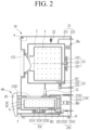
- FIG. 2 shows an embodiment of internal structures of the laundry washing machine 10 and the mini washing machine 60.
- the laundry washing machine 10 and the mini washing machine 60 may be independently constructed to be separated from each other.
- the laundry washing machine 10 may include a cabinet 1 that forms an appearance of the laundry washing machine, a tub 2 that is accommodated in the cabinet 1 and stores water therein, a drum 3 that is rotatably disposed in the tub 2 and stores water therein, a driver 32 that is coupled to the tub 2 to rotate the drum 3, a water supply 23 that is constructed to supply water to the tub 2, and a drainage 25 constructed to drain water of the tub 2.
- Each of the tub 2 and the drum 3 may have the laundry inlet for putting the laundry into the laundry washing machine in a front face thereof, and the cabinet 1 may further include a door 132 for opening and closing the laundry inlet.
- the driver 32 may include a stator 321 coupled to a rear face of the tub 2, a rotor 322 rotated by the stator 321, and a rotation shaft 323 coupled to the rotor 322 to rotate the drum 3.
- the water supply 23 may include a water supply pipe 231 that allows an external water supply source and the tub 2 to be in communication with each other, and a water supply valve 232 that opens and closes the water supply pipe 231.
- the water supply 23 may further include a detergent box that is able to be extended forwardly of the cabinet 1 and is constructed to put detergent into the tub 2, and the water supply pipe 231 may be in communication with the detergent box.
- the drainage 25 may include a drain pipe 251 disposed below the tub 2, and a drain pump 252 coupled to the drain pipe 252 to provide power for discharging water.
- the laundry washing machine 10 may further include a support 22 that supports the tub 2 to the cabinet 1, and a heater H1 that heats water inside the tub 2.
- the laundry washing machine 10 may further include a hot air supply Ha constructed to supply hot air to the tub 2.
- the laundry washing machine 10 may include a control panel P or a washing controller that receives a command for displaying or controlling the state of the laundry washing machine 10.
- the control panel P may be disposed coupled to the cabinet 1.
- control panel P may operate at least one of the driver 32, the water supply valve 232, the drain pump 252, the heater H1, and the hot air supply Ha to perform the arbitrary washing course and washing option for removing the foreign substances from the laundry.
- the washing course and the washing option may be composed of a series of control methods capable of performing all of a washing cycle, a rinsing cycle, and a dehydration cycle.
- the mini washing machine 60 may include a mini cabinet 1C that forms an appearance of the mini cabinet, a mini tub 2C that is accommodated in the mini cabinet 1C and stores water therein, a mini drum 3C that is rotatably disposed in the mini tub 2C and stores water therein, a mini driver 32C that is coupled to the mini tub 2C to rotate the mini drum 3C, a mini water supply 23C constructed to supply water to the mini tub 2C, and a mini drainage 25C constructed to drain water of the mini tub 2C.
- the mini cabinet 1C may be disposed beneath the cabinet 1 to support the cabinet 1. It is not excluded that the mini cabinet is placed on top of the cabinet 1.
- the mini cabinet may be formed integrally with the cabinet 1.
- Each of the mini tub 2C and the mini drum 3C may have the laundry inlet for putting the laundry into the mini washing machine in a top face thereof, and the mini laundry cabinet 1C may further include a mini door 132C for opening and closing the laundry inlet.
- the mini driver 32C may include a mini stator 321C coupled to a bottom face of the mini tub 2C, a mini rotor 322C rotated by the mini stator 321C, and a mini rotation shaft 323C coupled to the mini rotor 322C to rotate the mini drum 3C.
- the mini water supply 23C may include a mini water supply pipe 231C that allows the external water source and the mini tub 2C to be in communication with each other, and a mini water supply valve 232C that opens and closes the mini water supply pipe 231C.
- the mini water supply 23C may further include a mini detergent box that is able to be extended forwardly of the cabinet 1 and is constructed to put the detergent into the mini tub 2C, and the mini water supply pipe 231C may be in communication with the detergent box.
- the mini drainage 25C may include a mini drain pipe 251C disposed below the mini tub 2C, and a mini drain pump 252C coupled to the mini drain pipe 252C to provide power for discharging water.
- the mini washing machine 60 may further include a mini support 22C that supports the mini tub 2C to the mini cabinet 1C, and a mini heater H2 that heats water inside the mini tub 2C.
- the mini washing machine 60 may further include a hot air supply Hb constructed to supply hot air to the mini tub 2C.
- the mini washing machine 60 may include a mini control panel PC or a mini controller that receives a command for displaying or controlling the state of the mini washing machine 60.
- the mini control panel PC may be disposed coupled to the mini cabinet 1C.
- the mini control panel PC may operate at least one of the mini driver 32C, the mini water supply valve 232C, the mini drain pump 252C, the mini heater H2, and the mini hot air supply HaC to perform the arbitrary washing course and washing option for removing the foreign substances from the laundry.
- the washing course and the washing option may be composed of a series of control methods capable of performing all of the washing cycle, the rinsing cycle, and the dehydration cycle.
- the mini washing machine 60 may further include a drawer D that is able to be extended forwardly of the mini cabinet 1c and accommodates the mini tub 2c therein.
- the drawer D may include a front cover DC at a front face thereof to open and close an entrance through which the drawer D is extended from the mini cabinet 1C.
- the mini control panel PC may be disposed on the front cover DC.
- the washing machine 10 may execute cycles categorized into a washing cycle for removing contaminants from laundry using water mixed with detergent, a rinsing cycle for removing the contaminants and the detergent removed from the laundry by inputting clean water into the drum 3, and a dehydration cycle for removing water from the laundry by a physical force.
- a drying cycle for applying hot air may be further included.
- the drying cycle may not be able to be performed, and the drying cycle may be performed via a separate dryer.
- the washing machine 10 with the drum 3 senses a weight and a moment of inertia of the laundry before starting the washing cycle after putting the laundry into the drum 3 inside a cabinet.
- the weight of the laundry may be measured using a scale equipped in the drum 3.
- the weight of the laundry and the moment of inertia may be sensed to derive optimal RPM of the drum 3 and washing time.
- the weight is recognized to be greater than an actual amount of the laundry, so that the washing time is set to be great at an early stage. Therefore, when the washing time is not reduced later, the washing is performed for an unnecessarily great time, thereby damaging cloth of the laundry.
- turbidity sensed by a turbidity sensor 611 in the washing machine 10 may be inaccurately measured by the bubbles, and thus the rinsing time may be increased. To remove the bubbles, the washing time is increased, so that appropriate detergent should be used, but it is difficult for the user to know this.
- the present disclosure provides a washing machine accessory 600 inserted into the drum 3 to sense the situation inside the drum 3 and perform an optimized washing cycle based on the sensed situation.
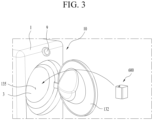
- FIG. 3 is a view illustrating a method for inserting the washing machine accessory 600 of the present disclosure into the washing machine 10.
- the washing machine accessory 600 of the present disclosure is positioned inside the drum 3 together with the laundry by being inserted to inside 135 of the drum 3 as a door 132 of the washing machine 10 is opened. Because the accessory 600 is located inside the drum 3 and is able to be in direct contact with the laundry, the accessory 600 may measure a more accurate value than other sensors located inside a cabinet 2 of the washing machine 10.
- the ball washing machine accessory inserted into the drum 3 of the washing machine 10 may have a spherical shape to rotate together with the rotation of the drum 3 and minimize friction with the fabric.
- the housing 610 may be formed in a cube shape as shown in FIG. 3 .
- a corner thereof may have a curved surface.
- the washing machine accessory 600 may prevent the laundry from tangling with each other when rotating in the drum 3, tap the fabric, and create a space between the laundry to increase a washing effect.
- the washing machine accessory 600 of the present disclosure may collect humidity, an impact amount, movement information, and the like inside the drum 3 and provide the collected information to the washing machine 10, thereby solving the problem that the cycle time of the washing machine 10 is inaccurate.
- the washing machine 10 may identify a state of the laundry, provide accurate time information to the user, and set a cycle time appropriate for the laundry and select an appropriate washing method therefor.
- FIG. 4 is a cross-sectional perspective view illustrating the washing machine accessory 600 of the present disclosure.
- the washing machine accessory 600 of the present disclosure may include a housing 610 in which a plurality of sensors are mounted, and the mounted sensors may include a humidity sensor 622, the turbidity sensor 611, the force sensor 623, a location information sensor 624 such as a gyro sensor, and the like.
- a battery (not shown) may be included to supply power to the sensor. Because a charging terminal for charging the battery has a waterproof problem, the charging terminal may be omitted and wireless charging may be performed via a wireless charging coil 631.
- a wireless communication module (not shown) for wireless communication with the washing machine 10 may be included to transmit the information collected by the sensor to the washing machine 10.
- the housing 610 may have the cube shape as shown in FIG. 3 .
- the housing 610 may be formed in a circular shape, but the cube shape is better for mounting the components inside. Further, the housing 610 needs to have a flat surface for the wireless charging coil 631 for the wireless charging to be in contact with a wireless charging device.
- the housing 610 may be formed in a hexahedral shape such that the force sensor 623 may accurately identify an impact direction, and may arrange the force sensors 623 on three surfaces. Even when the housing 610 has the cube shape, the corner thereof may be formed as the curved surface such that the laundry is not damaged.
- the housing 610 may include an elastic material such as rubber or silicon because noise may be generated by colliding with the drum 3.
- the washing machine 10 rotates the drum 3 to measure the weight of the laundry before the washing and to measure the moment of inertia.
- the washing machine accessory 600 of the present disclosure may include the humidity sensor 622 exposed to an outer surface of the housing 610.
- the humidity sensor 622 includes two electrodes 6221, and when moisture comes into contact with the electrodes, a current flows between the pair of electrodes 6221. Because the washing machine accessory 600 is put into the drum 3 and directly comes into contact with the laundry, when the laundry is wet, the current may flow through the pair of electrodes 6221 and this may be sensed by the humidity sensor 622.
- the dehydration cycle may be performed for about 1 minute to accurately measure the weight. Thereafter, the weight may be measured again to measure the accurate amount of laundry.
- the washing time may be set based on an amount of laundry smaller than the measured weight in consideration of the wetness.
- the force sensor 623 may be equipped to measure a volume as well.
- the force sensor 623 generates an electrical signal when a pressure is applied thereto.
- the force sensor 623 may be pressed to generate the signal.
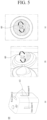
- FIG. 5 is a view illustrating an operation of the washing machine accessory 600 based on arrangement of the force sensors 623 and the volume of the laundry.
- the force sensors 623 may be disposed on the three surfaces of the cube-shaped housing.
- the present disclosure may not be necessarily limited thereto, and only one force sensor 623 may be equipped. However, the plurality of force sensors 623 directed in different directions may be included to measure an accurate amount of impact.
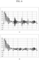
- FIG. 6 is a graph illustrating values sensed by the force sensor 623 of the washing machine accessory 600.
- the washing machine 10 may determine that the amount of laundry inside the drum 3 is small or the volume thereof is small.
- the user may be guided to insert more laundry because the amount of laundry is too small, and a dehydration cycle time may be set in consideration of the fact that it takes more time for balancing during the dehydration.
- the washing cycle time may be set small.
- the amount of impact sensed by the force sensor 623 is small as shown in (b) in FIG. 6 .
- the rinsing cycle time may be increased and a dehydration intensity may be increased.
- a washing mode may be changed to a blanket washing mode.
- a location detection sensor 624 that senses a change in a location of the washing machine accessory 600, such as the gyro sensor or an acceleration sensor, may be further included.
- the location detection sensor 624 may sense a movement of the washing machine accessory 600 in the drum 3.
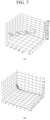
- FIG. 7 is a graph visualizing the movement of the washing machine accessory 600 measured by the location detection sensor 624.
- the washing machine accessory 600 moves while having a uniform pattern as shown in (a) in FIG. 7 , it means that the washing machine 10 maintains a stable level, and the laundry is evenly distributed in the drum 3.
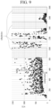
- FIG. 8 is a graph showing a result of measurement using a turbidity sensor disposed in the washing machine 10. Points on the graph have a very wide range of values measured by the turbidity sensor. Consistent appearance of the values equal to or higher than a certain level 200 at a lower portion of the graph reflects contamination levels of actual washing water. However, the reason for appearance of values in a higher and wider range is that bubbles have entered the turbidity sensor and thus accurate turbidity is not able to be measured.
- the turbidity sensor is located in a lower portion of the washing machine 10 and used for a long period of time, it is difficult for the turbidity sensor to exhibit the function thereof as contaminants such as water scale are attached thereto.
- the washing machine accessory 600 of the present disclosure may include the turbidity sensor 611 by itself to accurately measure a degree of contamination of washing water without being affected by the bubbles.
- FIG. 9 is a cross-sectional view of a flow channel 611 of the housing 610 of the present disclosure.
- the washing machine accessory 600 may include the flow channel 611 extending through the housing 610 and may include the turbidity sensor 611 disposed on the flow channel 611. One side and the other side of the flow channel 611 are connected to the outside of the housing 610, and washing water in the outside, that is, in the drum 3, may be introduced and pass through the flow channel 611.
- the flow channel 611 may have an inlet 612 and an outlet located in different directions, and may be composed of a first flow channel 6111 extending vertically from the inlet 612, a second flow channel 6112 bent from the first flow channel 6111, and a third flow channel 6113 bent again from the second flow channel 6112 and extending to the outlet.
- the inlet 612 and the outlet of the flow channel 611 are not necessarily distinguished from each other.
- One end of the flow channel 611 may be the inlet 612 into which washing water is introduced or the outlet.
- the first flow channel 6111 and the third flow channel 6113 may be arranged parallel to each other, and the second flow channel 6112 may be bent from the first flow channel 6111 to lower a flow rate of washing water introduced from the inlet 612.
- washing water flows too fast in the flow channel 611 it is difficult to measure the turbidity of washing water.
- the second flow channel 6112 may be constructed to have an angle of about 90° with respect to the first flow channel 6111. When the angle is too great, the flow rate may be too great, the angle may be too small, and a U-shaped section may be formed on the flow channel 611.
- the first flow channel 6111 may be constructed to have the angle of about 90° with the second flow channel 6112, and the second flow channel 6112 and the third flow channel 6113 may also be constructed to have an angle of about 90° therebetween.
- the bent portion on the flow channel 611 may be constructed to be curved such that washing water flows smoothly without impact.
- a piezo element 627 that applies shaking to the flow channel 611 may be added such that washing water passes through the flow channel 611 without accumulating. When an electrical signal is applied, vibration may be applied to promote the flow of washing water in the flow channel 611.
- the piezo element 627 is located at the outlet 612, but the location thereof may not be limited thereto.
- the piezo element 627 may be disposed in consideration of arrangement of the turbidity sensor 611 and other sensors, and may include a plurality of piezo elements.
- the turbidity sensor 611 located on the flow channel 611 may measure the turbidity of washing water introduced via the flow channel 611. As illustrated in FIG. 9 , the turbidity sensor 611 may be located at the same distance from both ends of the flow channel 611, and a light emitter 611a and a light receiver 611b may be disposed on both sides in a direction perpendicular to the extending direction of the flow channel 611.
- the light emitter 611a may include an LED module, and the light receiver 611b may include a photodiode.
- the light emitter 611a and the light receiver 611b are located inside the housing 610, but are exposed to moisture via the flow channel 611, so that they may be covered with a transparent waterproof cap.
- the rinsing cycle time may be set by measuring the degree of contamination of washing water using a degree to which light emitted from the light emitter 611a is received by the light receiver 611b.
- the inlet 612 and the outlet of the flow channel 611 may include mesh-shaped filters 615 through which the bubbles do not pass.
- the bubbles may be removed from washing water that has passed through the filter 615, so that the degree of contamination of washing water may be accurately measured.
- a cylindrical elastic tube 616 coupled to an inner surface of the filter 615 may be included to fix the filter 615 to the flow channel 611.
- the turbidity sensor 611 of the washing machine accessory 600 may sense the degree of contamination of washing water by measuring the turbidity of washing water from which the bubbles are removed, and may adjust the rinsing cycle time.
- the turbidity sensor disposed in the washing machine 10 itself is not able to accurately measure the degree of contamination of washing water because of the bubbles, but because not only the contaminants but also the bubbles need to be removed via the rinsing cycle, the value of the turbidity sensor of the washing machine 10 itself may also be used in determining the rinsing cycle time.
- the turbidity sensor of the washing machine 10 is contaminated, and the user may be guided to wash the turbidity sensor (see FIG. 12 ).
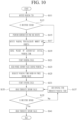
- FIG. 10 is a view illustrating a washing process using the washing machine accessory 600 of the present disclosure.
- a control method using information received from the washing machine accessory 600 is added to the process of washing without the washing machine accessory 600.
- a step with a color in the flowchart is related to the control method using the information collected from the washing machine accessory 600.
- the weight and the moment of inertia of the laundry for setting the washing time are calculated by rotating a washing tub (S111).
- the dehydration cycle (rough dehydration) may be performed for the accurate weight measurement (S115).
- the rough dehydration may be performed for a predetermined time or may be performed in proportion to the sensed weight. Because it is to reduce a weight error and not to increase the washing time, it is not necessary to completely dehydrate the laundry, so that the dehydration time does not need to be great. Therefore, in the present embodiment, it is set to 1 minute.
- the rough dehydration may be performed again.
- the weight and the moment of inertia may be calculated immediately without performing the additional rough dehydration (S117 and S119).
- the washing cycle time, the rinsing cycle time, and the dehydration cycle time may be set based on the measured weight and moment of inertia. In a future washing process, the time may be adjusted based on the turbidity of washing water, a material of the laundry, and the like.
- the washing cycle is a process of removing the contaminants by rotating the drum 3 after a certain amount of water and detergent are injected to induce the friction of the laundry. Unlike the dehydration cycle, the drum 3 rotates while changing a rotation direction and a rotation speed thereof is not too high.
- the washing machine accessory 600 positioned inside the drum 3 moves inside the drum 3, and rolls or falls inside the drum 3 when the amount of laundry is small or the volume of the laundry is small. At this time, the washing machine accessory 600 is subjected to a great impact.
- the impact amount of the washing machine accessory 600 may be small and a moving distance thereof may also be small.
- the amount of impact applied to the washing machine accessory 600 may be sensed (S123) using the force sensor 623 to extract characteristics of the laundry. For example, when the amount of impact is too small even though it is not in the blanket washing mode, the washing time may be adjusted by changing the washing mode to the blanket washing mode (S125).
- the washing machine accessory 600 based on the laundry may be extracted by integrating the information obtained by the location sensor such as the acceleration sensor or the gyro sensor described above.
- the material and the amount of the laundry may be identified only by inserting the washing machine accessory 600, and the optimal washing time and washing method may be set.
- the washing machine accessory 600 includes the plurality of force sensors 623, so that an accurate movement pattern of the washing machine accessory 600 may be obtained by integrating amounts of impact of the respective force sensors 623.
- the rinsing cycle is a cycle of removing the contaminants attached to the laundry and the detergent by injecting clean water into the drum 3, and is able to be performed a plurality of times.
- the rinsing cycle is performed a predetermined number of times or for a predetermined time based on the selected washing cycle, but when the degree of contamination sensed by the turbidity sensor 611 is not lowered to a reference value or lower (S133 and S135), the rinsing time and the number of rinsing cycles may be increased (S137).
- the degree of contamination of washing water may be accurately derived based on the information extracted from the washing machine accessory 600.
- the washing time may be readjusted by adding the rinsing time, and an amount of bubbles may also be measured using the value of the turbidity sensor 611 of the washing machine 10 itself.
- the turbidity sensor of the washing machine 10 itself is contaminated and the accurate value is not able to be extracted, only the value of the turbidity sensor 611 of the washing machine accessory 600 may be used.
- the rinsing cycle may be terminated and the dehydration cycle may be performed (S141).
- the washing time may be adjusted until a moisture level equal to or lower than a certain level is sensed using the humidity sensor 622 of the washing machine accessory 600.
- FIGS. 11 to 13 are views illustrating terminal screens for providing the user with a state of the washing machine 10 during the washing using the washing machine accessory 600 of the present disclosure and for performing control of the washing machine 10 via the external terminal.
- the washing machine 10 When the washing machine accessory 600 is put into the drum 3, the washing machine 10 may be connected to the accessory via short-range wireless communication such as Bluetooth or Wi-Fi, and may receive information on the washing machine accessory 600.
- short-range wireless communication such as Bluetooth or Wi-Fi
- the terminal may create or activate an icon 1 of the washing machine accessory 600 on the screen as shown in (a) in FIG. 11 .
- the information collected by the washing machine accessory 600 may be checked as shown in (b) in FIG. 11 .
- the washing machine accessory 600 may be in direct communication with the terminal to transmit the information thereto.
- the washing machine accessory 600 may display and provide a progress rate and a remaining time of the washing cycle 2.
- a washing force 3 may be provided based on the amount of impact sensed by the force sensor 623. As the amount of impact sensed by the force sensor 623 of the washing machine accessory 600 increases, the effect of causing the friction between the laundry and water is great, and thus the washing force is excellent. Based on this, the washing force may be numerically displayed.
- a rotation speed of the motor and the amount of impact of the force sensor 623 may be proportional, but as a use period increases, an RPM value of the motor of the washing machine 10 may decrease, so that the RPM value may be adjusted for increasing the washing force based on the value of the force sensor 623 of the washing machine accessory 600.
- the degree of contamination of washing water measured using the turbidity sensor 611 may be provided 4. In the drawing, only the value measured by the washing machine accessory 600 is displayed as the degree of contamination of washing water, but value of the turbidity sensor of the washing machine 10 may also be provided together.
- FIG. 12 illustrates screens for providing additional information to the user by comparing the degrees of contamination of washing water measured by the turbidity sensor 611 of the washing machine accessory 600 and the turbidity sensor of the washing machine 10 with each other. As shown in (a), whether the amount of bubbles is appropriate or whether the turbidity sensor of the washing machine 10 is contaminated may be determined by comparing the values of the two turbidity sensors with each other.
- information on the detergent dedicated for the drum 3 may be provided to the user to induce the user to use the detergent suitable for the washing machine 10.
- a button may be displayed to directly connect to a shopping mall for purchasing.
- the washing machine 10 may be controlled to update firmware to intensively supply washing water around the turbidity sensor and rotate the drum 3 to induce friction.
- whether the laundry is wet may be determined before the washing is performed and the determination result may be provided to the user 5, and whether the washing machine 10 is horizontal may be provided via the location detection sensor 624 to the user 6.
- FIG. 13 illustrates screens of a terminal for guiding to correct eccentricity by measuring the horizontality of the washing machine 10. As shown in (a) in FIG. 13 , the movement of the washing machine accessory 600 may be visually provided and a method for solving such problem may be guided.
- information on a method for manipulating the leveling leg on the floor to level the washing machine 10 may be specifically provided.
- the turbidity may be accurately measured using the washing machine accessory 600, so that the rinsing cycle time may be accurately calculated.
- the accurate amount of laundry may be calculated as the washing machine accessory 600 senses the humidity, so that the washing time may be optimally set.
- the type of laundry may be sensed via the amount of impact sensed by the washing machine accessory 600, so that the cycle based on the laundry may be selected and the washing may be performed.
- washing efficiency may be improved and noise may be reduced.
Landscapes
- Engineering & Computer Science (AREA)
- Textile Engineering (AREA)
- Computer Networks & Wireless Communication (AREA)
- Control Of Washing Machine And Dryer (AREA)
Abstract
Description
- The present disclosure relates to a washing machine accessory and a washing machine.
- Generally, a laundry treating apparatus may include a washing machine, a dryer, a styler, and the like, and the washing machine may have a drying function.
- The washing machine may execute cycles including a washing cycle, a rinsing cycle, and a dehydration cycle, and a washing time may be determined based on an initial washing course and a weight of laundry put into a drum. When an amount of laundry is too great or too small compared to a standard amount of laundry, it may affect the cycle time. In addition, when the laundry is wet, the laundry is determined to be heavier than an actual amount, so that there is a problem in that the cycle time is set to be unnecessarily great.
- A rinsing time may be determined based on an initially measured amount of laundry, but may be increased or decreased by measuring turbidity of washing water. In this regard, there is a problem in that the washing time is increased because it is difficult to accurately measure turbidity of detergent for general washing machines that produce too many bubbles.
- In the dehydration cycle, the laundry is uniformly distributed inside the drum, and then the drum is rotated at a high speed. In this regard, when the amount of laundry is too small, the laundry is not uniformly distributed, so that a time for balancing the drum by evenly distributing the laundry in the drum may be additionally required.
- As such, the washing time may be determined by various factors and may be changed from an initial scheduled washing time. However, when the washing time is changed, that is, the washing is performed too long than expected or is finished too early, a user has no choice but to leave the laundry unattended. Therefore, it is necessary to measure the accurate time initially and prevent the unnecessary changes in the washing time resulted from other factors at a time of subsequent adjustment.
- The present disclosure is to provide a washing machine accessory capable of accurately predicting a washing time.
- Provided is a washing machine accessory including a housing including a flow channel having both ends open, each filter that covers each of an inlet and an outlet of the flow channel and removes bubbles, a turbidity sensor formed on the flow channel, and a wireless communication module that transmits information received from the turbidity sensor to an external device.
- The washing machine accessory may further include an elastic tube coupled to an inner side of each filter and having an outer diameter corresponding to a size of the flow channel, and the elastic tube may be fitted into each of the inlet and the outlet of the flow channel to fix each filter.
- The turbidity sensor may include a light emitter and a light receiver arranged to face each other on both sides of one point of the flow channel.
- The flow channel may include a first flow channel extending from the inlet, a second flow channel bent from the first flow channel, and a third flow channel bent from the second flow channel and connected to the outlet, and the turbidity sensor may be located on the second flow channel.
- The first flow channel and the third flow channel may be parallel to each other.
- The washing machine accessory may further include a piezo element that applies vibration to the flow channel.
- The washing machine accessory may further include a contact-type humidity sensor exposed to an outer surface of the housing, and when the humidity sensor senses moisture, the wireless communication module may transmit sensed humidity to the external device.
- The washing machine accessory may further include a plurality of force sensors disposed on the housing, and the wireless communication module may transmit amounts of impact sensed by the force sensors to the external device.
- The he housing may have a cube shape having six surfaces, and the force sensors may be located on at least three of the surfaces.
- The washing machine accessory may further include a location information sensor including at least one of a gyro sensor and an acceleration sensor disposed in the housing, and the wireless communication module may transmit motion information of the housing obtained by the location information sensor to the external device.
- The housing may have a cube shape having six surfaces, and the washing machine accessory may further include a wireless charging coil disposed on one of the surfaces of the housing.
- Provided is a washing machine including a cabinet forming an outer appearance of the washing machine, a drum rotatably disposed in the cabinet and constructed to accommodate laundry therein, a driver that rotates the drum, a water supply that supplies water into the drum, a wireless communication module that transmits and receives a wireless signal, and a controller that controls the driver, the water supply, and the wireless communication module to perform a washing cycle, a rinsing cycle, and a dehydration cycle, wherein the wireless communication module receives first turbidity information provided by a washing machine accessory inserted into the drum, wherein a time of the rinsing cycle is reset based on the first turbidity information.
- The washing machine may further include a turbidity sensor positioned in a lower portion of the cabinet, and the controller may, when a difference between the first turbidity information received from the washing machine accessory and second turbidity information measured by the turbidity sensor is equal to or greater than a reference value, perform one of cleaning of the turbidity sensor and detergent change recommendation.
- The wireless communication module may receive humidity of the laundry provided by the washing machine accessory inserted into the drum, and the controller may, when the humidity is equal to or greater than a reference humidity, calculate a washing time by measuring a weight of the laundry in the drum and a rotational moment of inertia of the drum after performing a pre-dehydration cycle.
- The wireless communication module may receive an amount of impact provided by the washing machine accessory inserted into the drum, and the controller may calculate a washing time by determining that an amount of laundry is small when the amount of impact is equal to or greater than a first reference value, and determining that the amount of laundry is great when the amount of impact is equal to or smaller than a second reference value.
- The wireless communication module may receive motion information provided by the washing machine accessory inserted into the drum, and when the motion information exhibits an atypical pattern, a horizontality correction alarm of the washing machine may be provided.
- According to the present disclosure, the turbidity may be accurately measured using the washing machine accessory, so that the rinsing cycle time may be accurately calculated.
- In addition, the accurate amount of laundry may be calculated as the washing machine accessory senses the humidity, so that the washing time may be optimally set.
- In addition, the type of laundry may be sensed via the amount of impact sensed by the washing machine accessory, so that the cycle based on the laundry may be selected and the washing may be performed.
- In addition, as the inclination of the washing machine is sensed via the movement of the washing machine accessory and the user is guided to level the washing machine, washing efficiency may be improved and noise may be reduced.
- Additional scope of applicability of the present disclosure will become apparent from the detailed description below. However, because various changes and modifications within the spirit and scope of the present disclosure will be clearly understood by those skilled in the art, it should be understood that the detailed description and specific embodiments such as preferred embodiments of the present disclosure are given only as examples.
-
-
FIG. 1 shows a system having laundry treating apparatuses of the present disclosure. -
FIG. 2 shows structures of a laundry washing machine and a mini washing machine of a laundry treating apparatus of the present disclosure. -
FIG. 3 is a view illustrating a method for inserting a washing machine accessory of the present disclosure into a washing machine. -
FIG. 4 is a cross-sectional perspective view illustrating a washing machine accessory of the present disclosure. -
FIG. 5 is a view illustrating an operation of a washing machine accessory based on arrangement of a force sensors and a volume of laundry. -
FIG. 6 is a graph illustrating values sensed by a force sensor of a washing machine accessory. -
FIG. 7 is a graph visualizing a movement of a washing machine accessory measured by a location detection sensor. -
FIG. 8 is a graph showing a result of measurement using a turbidity sensor disposed in a washing machine. -
FIG. 9 is a cross-sectional view of a flow channel of a housing of the present disclosure. -
FIG. 10 is a view illustrating a washing process using a washing machine accessory of the present disclosure. -
FIGS. 11 to 13 are views illustrating terminal screens for providing a user with a state of a washing machine during washing using a washing machine accessory of the present disclosure and for performing control of the washing machine via the external terminal. - Hereinafter, embodiments disclosed in the present specification will be described in detail with reference to the accompanying drawings. In the present specification, even in different embodiments, the same and similar reference numerals are assigned to the same and similar components, and the description thereof is replaced with the first description. As used herein, the singular expression includes the plural expression unless the context clearly dictates otherwise. In addition, in describing the embodiments disclosed herein, when it is determined that a detailed description of a related known technology may obscure the gist of the embodiments disclosed herein, a detailed description thereof will be omitted. In addition, the accompanying drawings are only for easy understanding of the embodiments disclosed in the present specification, and it should be noted that the technical idea disclosed in the present specification is not to be construed as being limited by the accompanying drawings.
-
FIG. 1 shows a home appliance system and an online system in which a laundry treating apparatus of the present disclosure is disposed. - The laundry treating apparatus of the present disclosure may include a
laundry washing machine 10 that performs an arbitrary washing course or washing option that performs a washing cycle for removing foreign substances from laundry using water and detergent, and amini washing machine 60 that is disposed near or beneath the laundry washing machine and performs the arbitrary washing course or washing option that performs the washing cycle for removing the foreign substances from the laundry using the water and the detergent. - The
laundry washing machine 10 may be of a front load type in which the laundry is put into thelaundry washing machine 10 from a front face thereof, and themini washing machine 60 may be of a top load type in which the laundry is put into themini washing machine 60 from a top face thereof. - As shown, the
mini washing machine 60 may be disposed beneath thelaundry washing machine 10 to increase a vertical level of a laundry inlet of thelaundry washing machine 10. In this case, themini washing machine 60 may be of a drawer type of being extended frontwards such that a laundry inlet thereof into which the laundry is put is exposed. - In addition, the
mini washing machine 60 may be disposed on top of thelaundry washing machine 10. Accordingly, a user may easily access themini washing machine 60. - In one example, the laundry treating apparatus of the present disclosure may include a
laundry drying apparatus 20 that performs an arbitrary drying course or drying option that dries the laundry containing moisture after the washing is completed in thelaundry washing machine 10 or themini washing machine 60. - The user may arrange the
laundry washing machine 10 and thelaundry drying apparatus 20 among the laundry treating apparatus of the present disclosure together in the room, and may include all of the components of the laundry treating apparatus by additionally including themini washing machine 60. - Accordingly, the
mini washing machine 60 may wash laundry that has a relatively small volume and is frequently washed, such as underwear and baby clothes. In addition, thelaundry washing machine 10 may wash laundry that has a large volume and is infrequently washed, such as jeans and quilts. - In one example, at least one of the
laundry washing machine 10, thelaundry drying apparatus 20, and themini washing machine 60 may access an Internet network via a router (AP) 30. At least one of thelaundry washing machine 10, thelaundry drying apparatus 20, and themini washing machine 60 may have a communication module to connect to the router, and aserver 50 provided by a producer who produced the laundry treating apparatus may recognize thelaundry washing machine 10, thelaundry drying apparatus 20, and themini washing machine 60 via port information of therouter 30 and register and control thelaundry washing machine 10, thelaundry drying apparatus 20, and themini washing machine 60. - When the user has an
external terminal 40 equipped with a communication module, such as a smartphone, the user may access theserver 50 via the Internet network with theexternal terminal 40 to control at least one of thelaundry washing machine 10, thelaundry drying apparatus 20, and themini washing machine 60. - In addition, the user may register at least one of the
laundry washing machine 10, thelaundry drying apparatus 20, and themini washing machine 60 to theserver 50 via theexternal terminal 40. - In addition, when there is notification information or there is an update of the course or the option for at least one of the
laundry washing machine 10, thelaundry drying apparatus 20, and themini washing machine 60, theserver 50 may notify the user with theexternal terminal 40. - In one example, the
laundry washing machine 10, thelaundry drying apparatus 20, and themini washing machine 60 may be configured to be in communication with each other. - One of the
laundry washing machine 10, thelaundry drying apparatus 20, and themini washing machine 60 may be configured to be in communication with the other two via therouter 30 and theserver 50. To this end, each of thelaundry washing machine 10, thelaundry drying apparatus 20, and themini washing machine 60 may include the communication module such as WIFI. - In addition, the
laundry washing machine 10, thelaundry drying apparatus 20, and themini washing machine 60 may be configured to be in communication with each other without via theserver 50. For example, thelaundry washing machine 10, thelaundry drying apparatus 20, and themini washing machine 60 may be configured to be in communication with each other via a Bluetooth communication module. - The
laundry washing machine 10, thelaundry drying apparatus 20, and themini washing machine 60 may be configured to be in communication with each other to share the states thereof with each other and to display each other's states. - For example, the user may identify the states of the
laundry drying apparatus 20 and themini washing machine 60 via thelaundry washing machine 10. Therefore, even when thelaundry drying apparatus 20 and themini washing machine 60 are disposed to be spaced apart from thelaundry washing machine 10 or are disposed at positions where thelaundry drying apparatus 20 and themini washing machine 60 are not visible when the user looks at thelaundry washing machine 10, the user may display the states of thelaundry drying apparatus 20 and themini washing machine 60 via thelaundry washing machine 10. - The
laundry washing machine 10, thelaundry drying apparatus 20, and themini washing machine 60 may be configured to share names of a course or option thereof, a selected state of the course or option thereof, a executed state of the course or option thereof, a completion state of the course or option thereof, and an error or notification state thereof with each other or display each other's names and states of the courses or options and error or notification states. - In addition, one of the
laundry washing machine 10, thelaundry drying apparatus 20, and themini washing machine 60 may be configured to manipulate the other two with a manipulation portion thereof for receiving a command. - The
laundry washing machine 10, thelaundry drying apparatus 20, and themini washing machine 60 may transmit and receive control commands to and from each other via the respective communication modules thereof or theserver 50. - Accordingly, even when the
laundry washing machine 10, thelaundry drying apparatus 20, and themini washing machine 60 are spaced apart from each other, the user may control another device with one device, thereby improving convenience. -
FIG. 2 shows an embodiment of internal structures of thelaundry washing machine 10 and themini washing machine 60. - Unlike the drawing, the
laundry washing machine 10 and themini washing machine 60 may be independently constructed to be separated from each other. - The
laundry washing machine 10 may include acabinet 1 that forms an appearance of the laundry washing machine, atub 2 that is accommodated in thecabinet 1 and stores water therein, adrum 3 that is rotatably disposed in thetub 2 and stores water therein, adriver 32 that is coupled to thetub 2 to rotate thedrum 3, awater supply 23 that is constructed to supply water to thetub 2, and adrainage 25 constructed to drain water of thetub 2. - Each of the
tub 2 and thedrum 3 may have the laundry inlet for putting the laundry into the laundry washing machine in a front face thereof, and thecabinet 1 may further include adoor 132 for opening and closing the laundry inlet. - The
driver 32 may include astator 321 coupled to a rear face of thetub 2, arotor 322 rotated by thestator 321, and arotation shaft 323 coupled to therotor 322 to rotate thedrum 3. - The
water supply 23 may include awater supply pipe 231 that allows an external water supply source and thetub 2 to be in communication with each other, and awater supply valve 232 that opens and closes thewater supply pipe 231. - In one example, the
water supply 23 may further include a detergent box that is able to be extended forwardly of thecabinet 1 and is constructed to put detergent into thetub 2, and thewater supply pipe 231 may be in communication with the detergent box. - The
drainage 25 may include adrain pipe 251 disposed below thetub 2, and adrain pump 252 coupled to thedrain pipe 252 to provide power for discharging water. - The
laundry washing machine 10 may further include asupport 22 that supports thetub 2 to thecabinet 1, and a heater H1 that heats water inside thetub 2. - In addition, the
laundry washing machine 10 may further include a hot air supply Ha constructed to supply hot air to thetub 2. - In one example, the
laundry washing machine 10 may include a control panel P or a washing controller that receives a command for displaying or controlling the state of thelaundry washing machine 10. The control panel P may be disposed coupled to thecabinet 1. - In addition, the control panel P may operate at least one of the
driver 32, thewater supply valve 232, thedrain pump 252, the heater H1, and the hot air supply Ha to perform the arbitrary washing course and washing option for removing the foreign substances from the laundry. The washing course and the washing option may be composed of a series of control methods capable of performing all of a washing cycle, a rinsing cycle, and a dehydration cycle. - The
mini washing machine 60 may include a mini cabinet 1C that forms an appearance of the mini cabinet, amini tub 2C that is accommodated in the mini cabinet 1C and stores water therein, a mini drum 3C that is rotatably disposed in themini tub 2C and stores water therein, amini driver 32C that is coupled to themini tub 2C to rotate the mini drum 3C, amini water supply 23C constructed to supply water to themini tub 2C, and amini drainage 25C constructed to drain water of themini tub 2C. - The mini cabinet 1C may be disposed beneath the
cabinet 1 to support thecabinet 1. It is not excluded that the mini cabinet is placed on top of thecabinet 1. - The mini cabinet may be formed integrally with the
cabinet 1. - Each of the
mini tub 2C and the mini drum 3C may have the laundry inlet for putting the laundry into the mini washing machine in a top face thereof, and the mini laundry cabinet 1C may further include amini door 132C for opening and closing the laundry inlet. - The
mini driver 32C may include amini stator 321C coupled to a bottom face of themini tub 2C, a mini rotor 322C rotated by themini stator 321C, and a mini rotation shaft 323C coupled to the mini rotor 322C to rotate the mini drum 3C. - The
mini water supply 23C may include a miniwater supply pipe 231C that allows the external water source and themini tub 2C to be in communication with each other, and a miniwater supply valve 232C that opens and closes the miniwater supply pipe 231C. - In one example, the
mini water supply 23C may further include a mini detergent box that is able to be extended forwardly of thecabinet 1 and is constructed to put the detergent into themini tub 2C, and the miniwater supply pipe 231C may be in communication with the detergent box. - The
mini drainage 25C may include amini drain pipe 251C disposed below themini tub 2C, and a mini drain pump 252C coupled to the mini drain pipe 252C to provide power for discharging water. - The
mini washing machine 60 may further include a mini support 22C that supports themini tub 2C to the mini cabinet 1C, and a mini heater H2 that heats water inside themini tub 2C. - In addition, the
mini washing machine 60 may further include a hot air supply Hb constructed to supply hot air to themini tub 2C. - In one example, the
mini washing machine 60 may include a mini control panel PC or a mini controller that receives a command for displaying or controlling the state of themini washing machine 60. The mini control panel PC may be disposed coupled to the mini cabinet 1C. - In addition, the mini control panel PC may operate at least one of the
mini driver 32C, the miniwater supply valve 232C, the mini drain pump 252C, the mini heater H2, and the mini hot air supply HaC to perform the arbitrary washing course and washing option for removing the foreign substances from the laundry. The washing course and the washing option may be composed of a series of control methods capable of performing all of the washing cycle, the rinsing cycle, and the dehydration cycle. - The
mini washing machine 60 may further include a drawer D that is able to be extended forwardly of the mini cabinet 1c and accommodates the mini tub 2c therein. The drawer D may include a front cover DC at a front face thereof to open and close an entrance through which the drawer D is extended from the mini cabinet 1C. - The mini control panel PC may be disposed on the front cover DC.
- The
washing machine 10 may execute cycles categorized into a washing cycle for removing contaminants from laundry using water mixed with detergent, a rinsing cycle for removing the contaminants and the detergent removed from the laundry by inputting clean water into thedrum 3, and a dehydration cycle for removing water from the laundry by a physical force. - A drying cycle for applying hot air may be further included. When a heater is omitted in the
washing machine 10, the drying cycle may not be able to be performed, and the drying cycle may be performed via a separate dryer. - The
washing machine 10 with thedrum 3 senses a weight and a moment of inertia of the laundry before starting the washing cycle after putting the laundry into thedrum 3 inside a cabinet. The weight of the laundry may be measured using a scale equipped in thedrum 3. - However, depending on a type of laundry, even with the same weight, there may be laundry with a great moment of inertia, or the moment of inertia may appear small when the laundry is full in the
drum 3 without leaning to one side because of a great volume like a blanket. - Because the moment of inertia plays an important role in determining a washing force, the weight of the laundry and the moment of inertia may be sensed to derive optimal RPM of the
drum 3 and washing time. - However, there is a problem in that it is difficult to accurately set the washing time when an appropriate amount of laundry is not injected or appropriate detergent is not used.
- For example, when the amount of laundry is too small to generate a centrifugal force of the
drum 3, there is a problem in that a time taken to rotate thedrum 3 before the washing cycle or the dehydration cycle to balance the laundry is increased. - In addition, when the laundry is wet, the weight is recognized to be greater than an actual amount of the laundry, so that the washing time is set to be great at an early stage. Therefore, when the washing time is not reduced later, the washing is performed for an unnecessarily great time, thereby damaging cloth of the laundry.
- In addition, when detergent that produces too many bubbles is used, turbidity sensed by a
turbidity sensor 611 in thewashing machine 10 may be inaccurately measured by the bubbles, and thus the rinsing time may be increased. To remove the bubbles, the washing time is increased, so that appropriate detergent should be used, but it is difficult for the user to know this. - Because a sensor equipped in the
washing machine 10 itself is located outside thedrum 3, it is difficult to accurately sense a situation inside thedrum 3. Accordingly, the present disclosure provides awashing machine accessory 600 inserted into thedrum 3 to sense the situation inside thedrum 3 and perform an optimized washing cycle based on the sensed situation. -
FIG. 3 is a view illustrating a method for inserting thewashing machine accessory 600 of the present disclosure into thewashing machine 10. Thewashing machine accessory 600 of the present disclosure is positioned inside thedrum 3 together with the laundry by being inserted to inside 135 of thedrum 3 as adoor 132 of thewashing machine 10 is opened. Because theaccessory 600 is located inside thedrum 3 and is able to be in direct contact with the laundry, theaccessory 600 may measure a more accurate value than other sensors located inside acabinet 2 of thewashing machine 10. - The ball washing machine accessory inserted into the
drum 3 of thewashing machine 10 may have a spherical shape to rotate together with the rotation of thedrum 3 and minimize friction with the fabric. Alternatively, in consideration of convenience of charging, placement of aforce sensor 623, and the like, thehousing 610 may be formed in a cube shape as shown inFIG. 3 . However, to minimize the friction with the laundry, a corner thereof may have a curved surface. - The
washing machine accessory 600 may prevent the laundry from tangling with each other when rotating in thedrum 3, tap the fabric, and create a space between the laundry to increase a washing effect. - In particular, the
washing machine accessory 600 of the present disclosure may collect humidity, an impact amount, movement information, and the like inside thedrum 3 and provide the collected information to thewashing machine 10, thereby solving the problem that the cycle time of thewashing machine 10 is inaccurate. Using the information collected by thewashing machine accessory 600, thewashing machine 10 may identify a state of the laundry, provide accurate time information to the user, and set a cycle time appropriate for the laundry and select an appropriate washing method therefor. -
FIG. 4 is a cross-sectional perspective view illustrating thewashing machine accessory 600 of the present disclosure. Thewashing machine accessory 600 of the present disclosure may include ahousing 610 in which a plurality of sensors are mounted, and the mounted sensors may include ahumidity sensor 622, theturbidity sensor 611, theforce sensor 623, alocation information sensor 624 such as a gyro sensor, and the like. - A battery (not shown) may be included to supply power to the sensor. Because a charging terminal for charging the battery has a waterproof problem, the charging terminal may be omitted and wireless charging may be performed via a
wireless charging coil 631. - In addition, a wireless communication module (not shown) for wireless communication with the
washing machine 10 may be included to transmit the information collected by the sensor to thewashing machine 10. - The
housing 610 may have the cube shape as shown inFIG. 3 . Thehousing 610 may be formed in a circular shape, but the cube shape is better for mounting the components inside. Further, thehousing 610 needs to have a flat surface for thewireless charging coil 631 for the wireless charging to be in contact with a wireless charging device. - In addition, the
housing 610 may be formed in a hexahedral shape such that theforce sensor 623 may accurately identify an impact direction, and may arrange theforce sensors 623 on three surfaces. Even when thehousing 610 has the cube shape, the corner thereof may be formed as the curved surface such that the laundry is not damaged. - The
housing 610 may include an elastic material such as rubber or silicon because noise may be generated by colliding with thedrum 3. - As shown in
FIG. 3 , when thewashing machine accessory 600 is put into thedrum 3 together with the laundry, thewashing machine 10 rotates thedrum 3 to measure the weight of the laundry before the washing and to measure the moment of inertia. - In this regard, when the wet laundry is inserted, the weight is measured to be greater than the actual amount, so that the accurate amount of laundry may not be identified and the washing time may be increased. To sense whether the laundry is wet, the
washing machine accessory 600 of the present disclosure may include thehumidity sensor 622 exposed to an outer surface of thehousing 610. - The
humidity sensor 622 includes twoelectrodes 6221, and when moisture comes into contact with the electrodes, a current flows between the pair ofelectrodes 6221. Because thewashing machine accessory 600 is put into thedrum 3 and directly comes into contact with the laundry, when the laundry is wet, the current may flow through the pair ofelectrodes 6221 and this may be sensed by thehumidity sensor 622. - In other words, because it is the wet laundry, the weight thereof is greater than the actual amount. Therefore, the dehydration cycle may be performed for about 1 minute to accurately measure the weight. Thereafter, the weight may be measured again to measure the accurate amount of laundry. Alternatively, the washing time may be set based on an amount of laundry smaller than the measured weight in consideration of the wetness.
- Furthermore, to go beyond measuring the amount of laundry solely based on the weight, the
force sensor 623 may be equipped to measure a volume as well. Theforce sensor 623 generates an electrical signal when a pressure is applied thereto. When colliding with thedrum 3, theforce sensor 623 may be pressed to generate the signal. -
FIG. 5 is a view illustrating an operation of thewashing machine accessory 600 based on arrangement of theforce sensors 623 and the volume of the laundry. As shown in (a) inFIG. 5 , theforce sensors 623 may be disposed on the three surfaces of the cube-shaped housing. The present disclosure may not be necessarily limited thereto, and only oneforce sensor 623 may be equipped. However, the plurality offorce sensors 623 directed in different directions may be included to measure an accurate amount of impact. -
FIG. 6 is a graph illustrating values sensed by theforce sensor 623 of thewashing machine accessory 600. - When the amount of laundry is small as shown in (a) in
FIG. 5 , the number of times theforce sensor 623 of thewashing machine accessory 600 collides with thedrum 3 increases, so that a great impact may be sensed as shown in (a) inFIG. 6 . In this case, thewashing machine 10 may determine that the amount of laundry inside thedrum 3 is small or the volume thereof is small. - In this regard, the user may be guided to insert more laundry because the amount of laundry is too small, and a dehydration cycle time may be set in consideration of the fact that it takes more time for balancing during the dehydration. However, because the amount of laundry is small, the washing cycle time may be set small.
- In one example, as shown in (c) in
FIG. 5 , in case of the laundry having the great volume such as the blanket, the amount of impact sensed by theforce sensor 623 is small as shown in (b) inFIG. 6 . Considering that the laundry with the great volume consumes a lot of water, the rinsing cycle time may be increased and a dehydration intensity may be increased. A washing mode may be changed to a blanket washing mode. - A
location detection sensor 624 that senses a change in a location of thewashing machine accessory 600, such as the gyro sensor or an acceleration sensor, may be further included. Thelocation detection sensor 624 may sense a movement of thewashing machine accessory 600 in thedrum 3. -
FIG. 7 is a graph visualizing the movement of thewashing machine accessory 600 measured by thelocation detection sensor 624. When thewashing machine accessory 600 moves while having a uniform pattern as shown in (a) inFIG. 7 , it means that thewashing machine 10 maintains a stable level, and the laundry is evenly distributed in thedrum 3. - However, as shown in (b) in
FIG. 7 , when the movement of thewashing machine accessory 600 exhibits a pattern of flowing down in one direction, it indicates that thewashing machine 10 is not balanced, so that thewashing machine 10 needs to be leveled. Therefore, an inclined direction of the washing machine may be sensed, and the user may be guided to level the washing machine. In addition, a degree of inclination may be sensed to suggest a rotation direction and the number of rotations of a leveling leg on the floor to the user (seeFIG. 13 ). -
FIG. 8 is a graph showing a result of measurement using a turbidity sensor disposed in thewashing machine 10. Points on the graph have a very wide range of values measured by the turbidity sensor. Consistent appearance of the values equal to or higher than acertain level 200 at a lower portion of the graph reflects contamination levels of actual washing water. However, the reason for appearance of values in a higher and wider range is that bubbles have entered the turbidity sensor and thus accurate turbidity is not able to be measured. - As the number of rinses increases, the bubbles decrease, the turbidity is lowered, and washing water becomes clearer, but it is difficult to accurately measure the turbidity because of the bubbles. In addition, when the turbidity sensor is located in a lower portion of the
washing machine 10 and used for a long period of time, it is difficult for the turbidity sensor to exhibit the function thereof as contaminants such as water scale are attached thereto. - Accordingly, the
washing machine accessory 600 of the present disclosure may include theturbidity sensor 611 by itself to accurately measure a degree of contamination of washing water without being affected by the bubbles.FIG. 9 is a cross-sectional view of aflow channel 611 of thehousing 610 of the present disclosure. - The
washing machine accessory 600 may include theflow channel 611 extending through thehousing 610 and may include theturbidity sensor 611 disposed on theflow channel 611. One side and the other side of theflow channel 611 are connected to the outside of thehousing 610, and washing water in the outside, that is, in thedrum 3, may be introduced and pass through theflow channel 611. - The
flow channel 611 may have aninlet 612 and an outlet located in different directions, and may be composed of afirst flow channel 6111 extending vertically from theinlet 612, asecond flow channel 6112 bent from thefirst flow channel 6111, and athird flow channel 6113 bent again from thesecond flow channel 6112 and extending to the outlet. - The
inlet 612 and the outlet of theflow channel 611 are not necessarily distinguished from each other. One end of theflow channel 611 may be theinlet 612 into which washing water is introduced or the outlet. - The
first flow channel 6111 and thethird flow channel 6113 may be arranged parallel to each other, and thesecond flow channel 6112 may be bent from thefirst flow channel 6111 to lower a flow rate of washing water introduced from theinlet 612. When washing water flows too fast in theflow channel 611, it is difficult to measure the turbidity of washing water. - The
second flow channel 6112 may be constructed to have an angle of about 90° with respect to thefirst flow channel 6111. When the angle is too great, the flow rate may be too great, the angle may be too small, and a U-shaped section may be formed on theflow channel 611. - Because there is a problem in that washing water accumulates in the U-shaped bent portion, as shown in
FIG. 9 , thefirst flow channel 6111 may be constructed to have the angle of about 90° with thesecond flow channel 6112, and thesecond flow channel 6112 and thethird flow channel 6113 may also be constructed to have an angle of about 90° therebetween. The bent portion on theflow channel 611 may be constructed to be curved such that washing water flows smoothly without impact. - A
piezo element 627 that applies shaking to theflow channel 611 may be added such that washing water passes through theflow channel 611 without accumulating. When an electrical signal is applied, vibration may be applied to promote the flow of washing water in theflow channel 611. - In the present embodiment, the
piezo element 627 is located at theoutlet 612, but the location thereof may not be limited thereto. Thepiezo element 627 may be disposed in consideration of arrangement of theturbidity sensor 611 and other sensors, and may include a plurality of piezo elements. - The
turbidity sensor 611 located on theflow channel 611 may measure the turbidity of washing water introduced via theflow channel 611. As illustrated inFIG. 9 , theturbidity sensor 611 may be located at the same distance from both ends of theflow channel 611, and a light emitter 611a and a light receiver 611b may be disposed on both sides in a direction perpendicular to the extending direction of theflow channel 611. - The light emitter 611a may include an LED module, and the light receiver 611b may include a photodiode. The light emitter 611a and the light receiver 611b are located inside the
housing 610, but are exposed to moisture via theflow channel 611, so that they may be covered with a transparent waterproof cap. The rinsing cycle time may be set by measuring the degree of contamination of washing water using a degree to which light emitted from the light emitter 611a is received by the light receiver 611b. - To remove the bubbles of washing water introduced into the
flow channel 611, theinlet 612 and the outlet of theflow channel 611 may include mesh-shapedfilters 615 through which the bubbles do not pass. The bubbles may be removed from washing water that has passed through thefilter 615, so that the degree of contamination of washing water may be accurately measured. A cylindricalelastic tube 616 coupled to an inner surface of thefilter 615 may be included to fix thefilter 615 to theflow channel 611. - The
turbidity sensor 611 of thewashing machine accessory 600 may sense the degree of contamination of washing water by measuring the turbidity of washing water from which the bubbles are removed, and may adjust the rinsing cycle time. - The turbidity sensor disposed in the
washing machine 10 itself is not able to accurately measure the degree of contamination of washing water because of the bubbles, but because not only the contaminants but also the bubbles need to be removed via the rinsing cycle, the value of the turbidity sensor of thewashing machine 10 itself may also be used in determining the rinsing cycle time. - When a difference between the values of the turbidity sensor of the
washing machine 10 and theturbidity sensor 611 of thewashing machine accessory 600 is too great even after the rinsing cycle is repeated a plurality of times, it may be determined that there are a lot of bubbles, and it may be suggested to the user to use detergent that generates fewer bubbles. - Alternatively, it may be considered that the turbidity sensor of the
washing machine 10 is contaminated, and the user may be guided to wash the turbidity sensor (seeFIG. 12 ). -
FIG. 10 is a view illustrating a washing process using thewashing machine accessory 600 of the present disclosure. A control method using information received from thewashing machine accessory 600 is added to the process of washing without thewashing machine accessory 600. A step with a color in the flowchart is related to the control method using the information collected from thewashing machine accessory 600. - First, the weight and the moment of inertia of the laundry for setting the washing time are calculated by rotating a washing tub (S111). In this regard, when moisture is sensed (S113) by the sensor of the
washing machine 10, it may be determined that the laundry is wet, and the dehydration cycle (rough dehydration) may be performed for the accurate weight measurement (S115). - The rough dehydration may be performed for a predetermined time or may be performed in proportion to the sensed weight. Because it is to reduce a weight error and not to increase the washing time, it is not necessary to completely dehydrate the laundry, so that the dehydration time does not need to be great. Therefore, in the present embodiment, it is set to 1 minute.
- In this regard, when the moisture measurement is performed again and the humidity does not fall to a predetermined level or lower, the rough dehydration may be performed again. However, so as not to increase the washing time, the weight and the moment of inertia may be calculated immediately without performing the additional rough dehydration (S117 and S119).
- The washing cycle time, the rinsing cycle time, and the dehydration cycle time may be set based on the measured weight and moment of inertia. In a future washing process, the time may be adjusted based on the turbidity of washing water, a material of the laundry, and the like.
- When the weight of the laundry and the moment of inertia of the
drum 3 are completely calculated, the washing cycle is started (S121). The washing cycle is a process of removing the contaminants by rotating thedrum 3 after a certain amount of water and detergent are injected to induce the friction of the laundry. Unlike the dehydration cycle, thedrum 3 rotates while changing a rotation direction and a rotation speed thereof is not too high. - In this regard, the
washing machine accessory 600 positioned inside thedrum 3 moves inside thedrum 3, and rolls or falls inside thedrum 3 when the amount of laundry is small or the volume of the laundry is small. At this time, thewashing machine accessory 600 is subjected to a great impact. - In one example, because the laundry is soft in a case of winter clothes or the blanket containing cotton, the impact amount of the
washing machine accessory 600 may be small and a moving distance thereof may also be small. - The amount of impact applied to the
washing machine accessory 600 may be sensed (S123) using theforce sensor 623 to extract characteristics of the laundry. For example, when the amount of impact is too small even though it is not in the blanket washing mode, the washing time may be adjusted by changing the washing mode to the blanket washing mode (S125). - Alternatively, when the amount of impact is great, it may be determined that the laundry is thin or the amount of laundry is small, and the washing time and pattern may be adjusted. In addition, the movement of the
washing machine accessory 600 based on the laundry may be extracted by integrating the information obtained by the location sensor such as the acceleration sensor or the gyro sensor described above. - When the pattern of the
force sensor 623 is learned using artificial intelligence, the material and the amount of the laundry may be identified only by inserting thewashing machine accessory 600, and the optimal washing time and washing method may be set. - In particular, the
washing machine accessory 600 according to the present disclosure includes the plurality offorce sensors 623, so that an accurate movement pattern of thewashing machine accessory 600 may be obtained by integrating amounts of impact of therespective force sensors 623. - When the washing cycle is terminated, the rinsing cycle is performed (S131). The rinsing cycle is a cycle of removing the contaminants attached to the laundry and the detergent by injecting clean water into the
drum 3, and is able to be performed a plurality of times. - In general, the rinsing cycle is performed a predetermined number of times or for a predetermined time based on the selected washing cycle, but when the degree of contamination sensed by the
turbidity sensor 611 is not lowered to a reference value or lower (S133 and S135), the rinsing time and the number of rinsing cycles may be increased (S137). - In this regard, because the value obtained by the turbidity sensor of the
washing machine 10 itself may be the inaccurate value because of the bubbles, the degree of contamination of washing water may be accurately derived based on the information extracted from thewashing machine accessory 600. - When the value of the
turbidity sensor 611 is equal to or greater than a specific turbidity, the washing time may be readjusted by adding the rinsing time, and an amount of bubbles may also be measured using the value of theturbidity sensor 611 of thewashing machine 10 itself. However, as described above, when the turbidity sensor of thewashing machine 10 itself is contaminated and the accurate value is not able to be extracted, only the value of theturbidity sensor 611 of thewashing machine accessory 600 may be used. - When the error between the value of the
turbidity sensor 611 of thewashing machine accessory 600 and the value of the turbidity sensor of thewashing machine 10 is great, it may be determined that the turbidity sensor of thewashing machine 10 is contaminated, and the user may be guided to wash the turbidity sensor. - When the turbidity is lowered to the reference value or lower, the rinsing cycle may be terminated and the dehydration cycle may be performed (S141). During the dehydration cycle, the washing time may be adjusted until a moisture level equal to or lower than a certain level is sensed using the
humidity sensor 622 of thewashing machine accessory 600. -
FIGS. 11 to 13 are views illustrating terminal screens for providing the user with a state of thewashing machine 10 during the washing using thewashing machine accessory 600 of the present disclosure and for performing control of thewashing machine 10 via the external terminal. - When the
washing machine accessory 600 is put into thedrum 3, thewashing machine 10 may be connected to the accessory via short-range wireless communication such as Bluetooth or Wi-Fi, and may receive information on thewashing machine accessory 600. - By transmitting such information to the terminal connected to the
washing machine 10, the terminal may create or activate anicon ① of thewashing machine accessory 600 on the screen as shown in (a) inFIG. 11 . When the icon is selected, the information collected by thewashing machine accessory 600 may be checked as shown in (b) inFIG. 11 . Alternatively, thewashing machine accessory 600 may be in direct communication with the terminal to transmit the information thereto. - The
washing machine accessory 600 may display and provide a progress rate and a remaining time of thewashing cycle ②. Awashing force ③ may be provided based on the amount of impact sensed by theforce sensor 623. As the amount of impact sensed by theforce sensor 623 of thewashing machine accessory 600 increases, the effect of causing the friction between the laundry and water is great, and thus the washing force is excellent. Based on this, the washing force may be numerically displayed. A rotation speed of the motor and the amount of impact of theforce sensor 623 may be proportional, but as a use period increases, an RPM value of the motor of thewashing machine 10 may decrease, so that the RPM value may be adjusted for increasing the washing force based on the value of theforce sensor 623 of thewashing machine accessory 600. - The degree of contamination of washing water measured using the
turbidity sensor 611 may be provided ④. In the drawing, only the value measured by thewashing machine accessory 600 is displayed as the degree of contamination of washing water, but value of the turbidity sensor of thewashing machine 10 may also be provided together. -
FIG. 12 illustrates screens for providing additional information to the user by comparing the degrees of contamination of washing water measured by theturbidity sensor 611 of thewashing machine accessory 600 and the turbidity sensor of thewashing machine 10 with each other. As shown in (a), whether the amount of bubbles is appropriate or whether the turbidity sensor of thewashing machine 10 is contaminated may be determined by comparing the values of the two turbidity sensors with each other. - As shown in (b), information on the detergent dedicated for the
drum 3 may be provided to the user to induce the user to use the detergent suitable for thewashing machine 10. A button may be displayed to directly connect to a shopping mall for purchasing. - As shown in (c), it may be determined that the turbidity sensor of the
washing machine 10 is contaminated, and the turbidity sensor inside thewashing machine 10 may be washed. In a case of thewashing machine 10 not equipped with the washing function of the turbidity sensor, thewashing machine 10 may be controlled to update firmware to intensively supply washing water around the turbidity sensor and rotate thedrum 3 to induce friction. - As shown in (b) in
FIG. 11 , whether the laundry is wet may be determined before the washing is performed and the determination result may be provided to theuser ⑤, and whether thewashing machine 10 is horizontal may be provided via thelocation detection sensor 624 to theuser ⑥. -
FIG. 13 illustrates screens of a terminal for guiding to correct eccentricity by measuring the horizontality of thewashing machine 10. As shown in (a) inFIG. 13 , the movement of thewashing machine accessory 600 may be visually provided and a method for solving such problem may be guided. - As shown in (b), information on a method for manipulating the leveling leg on the floor to level the
washing machine 10 may be specifically provided. - According to the present disclosure, the turbidity may be accurately measured using the
washing machine accessory 600, so that the rinsing cycle time may be accurately calculated. - In addition, the accurate amount of laundry may be calculated as the
washing machine accessory 600 senses the humidity, so that the washing time may be optimally set. - In addition, the type of laundry may be sensed via the amount of impact sensed by the
washing machine accessory 600, so that the cycle based on the laundry may be selected and the washing may be performed. - In addition, as the inclination of the
washing machine 10 is sensed via the movement of thewashing machine accessory 600 and the user is guided to level thewashing machine 10, washing efficiency may be improved and noise may be reduced. - The above detailed description should not be construed as limiting in all respects but should be considered as illustrative. The scope of the present disclosure should be determined by a reasonable interpretation of the appended claims, and all changes within the equivalent scope of the present disclosure are included in the scope of the present disclosure.
Claims (16)
- A washing machine accessory comprising:a housing including a flow channel having both ends open;each filter covering each of an inlet and an outlet of the flow channel and configured to remove bubbles;a turbidity sensor formed on the flow channel; anda wireless communication module configured to transmit information received from the turbidity sensor to an external device.
- The washing machine accessory of claim 1, further comprising an elastic tube coupled to an inner side of each filter and having an outer diameter corresponding to a size of the flow channel,
wherein the elastic tube is fitted into each of the inlet and the outlet of the flow channel to fix each filter. - The washing machine accessory of claim 1, wherein the turbidity sensor includes a light emitter and a light receiver arranged to face each other on both sides of one point of the flow channel.
- The washing machine accessory of claim 1, wherein the flow channel includes:a first flow channel extending from the inlet;a second flow channel bent from the first flow channel; anda third flow channel bent from the second flow channel and connected to the outlet,wherein the turbidity sensor is located on the second flow channel.
- The washing machine accessory of claim 4, wherein the first flow channel and the third flow channel are parallel to each other.
- The washing machine accessory of claim 1, further comprising a piezo element configured to apply vibration to the flow channel.
- The washing machine accessory of claim 1, further comprising a contact-type humidity sensor exposed to an outer surface of the housing,
wherein when the humidity sensor senses moisture, the wireless communication module transmits sensed humidity to the external device. - The washing machine accessory of claim 1, further comprising a plurality of force sensors disposed on the housing,
wherein the wireless communication module transmits amounts of impact sensed by the force sensors to the external device. - The washing machine accessory of claim 8, wherein the housing has a cube shape having six surfaces,
wherein the force sensors are located on at least three of the surfaces. - The washing machine accessory of claim 1, further comprising a location information sensor including at least one of a gyro sensor and an acceleration sensor disposed in the housing,
wherein the wireless communication module transmits motion information of the housing obtained by the location information sensor to the external device. - The washing machine accessory of claim 1, wherein the housing has a cube shape having six surfaces,
wherein the washing machine accessory further includes a wireless charging coil disposed on one of the surfaces of the housing. - A washing machine comprising:a cabinet forming an outer appearance of the washing machine;a drum rotatably disposed in the cabinet and constructed to accommodate laundry therein;a driver configured to rotate the drum;a water supply configured to supply water into the drum;a wireless communication module configured to transmit and receive a wireless signal; anda controller configured to control the driver, the water supply, and the wireless communication module to perform a washing cycle, a rinsing cycle, and a dehydration cycle,wherein the wireless communication module receives first turbidity information provided by a washing machine accessory inserted into the drum,wherein a time of the rinsing cycle is reset based on the first turbidity information.
- The washing machine of claim 12, further comprising a turbidity sensor positioned in a lower portion of the cabinet,
wherein the controller is configured to, when a difference between the first turbidity information received from the washing machine accessory and second turbidity information measured by the turbidity sensor is equal to or greater than a reference value, perform one of cleaning of the turbidity sensor and detergent change recommendation. - The washing machine of claim 12, wherein the wireless communication module receives humidity of the laundry provided by the washing machine accessory inserted into the drum,
wherein the controller is configured to, when the humidity is equal to or greater than a reference humidity, calculate a washing time by measuring a weight of the laundry in the drum and a rotational moment of inertia of the drum after performing a pre-dehydration cycle. - The washing machine of claim 12, wherein the wireless communication module receives an amount of impact provided by the washing machine accessory inserted into the drum,
wherein the controller is configured to calculate a washing time by determining that an amount of laundry is small when the amount of impact is equal to or greater than a first reference value, and determining that the amount of laundry is great when the amount of impact is equal to or smaller than a second reference value. - The washing machine of claim 12, wherein the wireless communication module receives motion information provided by the washing machine accessory inserted into the drum,
wherein when the motion information exhibits an atypical pattern, a horizontality correction alarm of the washing machine is provided.
Applications Claiming Priority (1)
| Application Number | Priority Date | Filing Date | Title |
|---|---|---|---|
| PCT/KR2022/013862 WO2024058291A1 (en) | 2022-09-16 | 2022-09-16 | Washing machine accessory, and washing machine |
Publications (2)
| Publication Number | Publication Date |
|---|---|
| EP4556615A1 true EP4556615A1 (en) | 2025-05-21 |
| EP4556615A4 EP4556615A4 (en) | 2025-08-20 |
Family
ID=90275353
Family Applications (1)
| Application Number | Title | Priority Date | Filing Date |
|---|---|---|---|
| EP22958894.2A Pending EP4556615A4 (en) | 2022-09-16 | 2022-09-16 | Washing machine accessory, and washing machine |
Country Status (4)
| Country | Link |
|---|---|
| EP (1) | EP4556615A4 (en) |
| KR (1) | KR20250038666A (en) |
| CN (1) | CN119816635A (en) |
| WO (1) | WO2024058291A1 (en) |
Family Cites Families (7)
| Publication number | Priority date | Publication date | Assignee | Title |
|---|---|---|---|---|
| KR20170115749A (en) * | 2016-04-08 | 2017-10-18 | 엘지전자 주식회사 | Accessory for washing machine |
| DE102016225854A1 (en) * | 2016-12-21 | 2018-06-21 | Henkel Ag & Co. Kgaa | Retrofittable sensor unit for controlling a dosing device |
| KR101959303B1 (en) * | 2017-08-23 | 2019-03-18 | 엘지전자 주식회사 | Laundry treating apparatus |
| KR101957166B1 (en) * | 2017-08-23 | 2019-07-04 | 엘지전자 주식회사 | Laundry treating apparatus |
| KR102752482B1 (en) * | 2019-05-22 | 2025-01-10 | 삼성전자주식회사 | Sensor device and electronic device obtaining information therefrom |
| KR102822651B1 (en) * | 2019-12-30 | 2025-06-20 | 삼성전자주식회사 | Washing machine and method for controlling the same |
| KR20220081157A (en) * | 2020-12-08 | 2022-06-15 | 삼성전자주식회사 | Electronic device and mehtod for registering a sensor ball in the electronic device |
-
2022
- 2022-09-16 CN CN202280099739.5A patent/CN119816635A/en active Pending
- 2022-09-16 WO PCT/KR2022/013862 patent/WO2024058291A1/en not_active Ceased
- 2022-09-16 KR KR1020257003843A patent/KR20250038666A/en active Pending
- 2022-09-16 EP EP22958894.2A patent/EP4556615A4/en active Pending
Also Published As
| Publication number | Publication date |
|---|---|
| KR20250038666A (en) | 2025-03-19 |
| EP4556615A4 (en) | 2025-08-20 |
| WO2024058291A1 (en) | 2024-03-21 |
| CN119816635A (en) | 2025-04-11 |
Similar Documents
| Publication | Publication Date | Title |
|---|---|---|
| KR102469629B1 (en) | Laundry treating apparatus | |
| US11512420B2 (en) | Washing machine and control method thereof | |
| EP2811060B1 (en) | Methods of determining a load size in a laundry treating appliance | |
| US7930786B2 (en) | Method for determining load size and/or setting water level in a washing machine | |
| KR102572096B1 (en) | Washing apparatus, and control method for the same | |
| US7930787B2 (en) | Method for determining load size and/or setting water level in a washing machine | |
| KR20100005436A (en) | Drum washer and control method for the same | |
| US20160305060A1 (en) | Laundry treating appliance lint filter | |
| KR20170115749A (en) | Accessory for washing machine | |
| JP2020171513A (en) | Washing machine and washing system | |
| KR102428212B1 (en) | Device for treating laundry and Controlling method for the same | |
| KR101939089B1 (en) | Laundry treating apparatus | |
| EP4556615A1 (en) | Washing machine accessory, and washing machine | |
| JP2008237646A (en) | Drum washing machine | |
| EP4324974A1 (en) | Washing machine and method for controlling same | |
| US20140020482A1 (en) | Detecting satellization of a laundry load | |
| KR20140101089A (en) | Clothing dryer and control method thereof | |
| KR102771869B1 (en) | Control method for an Laundry Treating Apparatus | |
| KR102627368B1 (en) | A washing machine and method for determining a washing of a tub of the washing machine, and a server and a program therefor | |
| KR20150052696A (en) | Washing machine with mems sensor and spin-dry control method thereof | |
| KR102077569B1 (en) | Laundry treating apparatus | |
| US20230134144A1 (en) | Systems and methods for adjusting a washing operation based on feedback from a drying operation | |
| US20220145510A1 (en) | Washing machine appliance and method of determining the remaining moisture content of a load of clothes | |
| KR101114206B1 (en) | Method and apparatus for controlling dry level of a drum type washing machine | |
| KR20240126714A (en) | Method for providing water usage and washing machine thereof |
Legal Events
| Date | Code | Title | Description |
|---|---|---|---|
| STAA | Information on the status of an ep patent application or granted ep patent |
Free format text: STATUS: THE INTERNATIONAL PUBLICATION HAS BEEN MADE |
|
| PUAI | Public reference made under article 153(3) epc to a published international application that has entered the european phase |
Free format text: ORIGINAL CODE: 0009012 |
|
| STAA | Information on the status of an ep patent application or granted ep patent |
Free format text: STATUS: REQUEST FOR EXAMINATION WAS MADE |
|
| 17P | Request for examination filed |
Effective date: 20250215 |
|
| AK | Designated contracting states |
Kind code of ref document: A1 Designated state(s): AL AT BE BG CH CY CZ DE DK EE ES FI FR GB GR HR HU IE IS IT LI LT LU LV MC MK MT NL NO PL PT RO RS SE SI SK SM TR |
|
| REG | Reference to a national code |
Ref country code: DE Ref legal event code: R079 Free format text: PREVIOUS MAIN CLASS: D06F0034220000 Ipc: D06F0034050000 |
|
| A4 | Supplementary search report drawn up and despatched |
Effective date: 20250722 |
|
| RIC1 | Information provided on ipc code assigned before grant |
Ipc: D06F 34/05 20200101AFI20250716BHEP Ipc: D06F 34/18 20200101ALI20250716BHEP Ipc: D06F 34/22 20200101ALI20250716BHEP Ipc: D06F 103/04 20200101ALN20250716BHEP Ipc: D06F 103/08 20200101ALN20250716BHEP Ipc: D06F 103/20 20200101ALN20250716BHEP |
|
| DAV | Request for validation of the european patent (deleted) | ||
| DAX | Request for extension of the european patent (deleted) |