EP4556410A1 - Transfer device - Google Patents
Transfer device Download PDFInfo
- Publication number
- EP4556410A1 EP4556410A1 EP23860805.3A EP23860805A EP4556410A1 EP 4556410 A1 EP4556410 A1 EP 4556410A1 EP 23860805 A EP23860805 A EP 23860805A EP 4556410 A1 EP4556410 A1 EP 4556410A1
- Authority
- EP
- European Patent Office
- Prior art keywords
- center plate
- transfer device
- plate
- battery cell
- support plate
- Prior art date
- Legal status (The legal status is an assumption and is not a legal conclusion. Google has not performed a legal analysis and makes no representation as to the accuracy of the status listed.)
- Pending
Links
Images




Classifications
-
- B—PERFORMING OPERATIONS; TRANSPORTING
- B65—CONVEYING; PACKING; STORING; HANDLING THIN OR FILAMENTARY MATERIAL
- B65G—TRANSPORT OR STORAGE DEVICES, e.g. CONVEYORS FOR LOADING OR TIPPING, SHOP CONVEYOR SYSTEMS OR PNEUMATIC TUBE CONVEYORS
- B65G17/00—Conveyors having an endless traction element, e.g. a chain, transmitting movement to a continuous or substantially-continuous load-carrying surface or to a series of individual load-carriers; Endless-chain conveyors in which the chains form the load-carrying surface
- B65G17/30—Details; Auxiliary devices
- B65G17/46—Means for holding or retaining the loads in fixed position on the load-carriers, e.g. magnetic
-
- B—PERFORMING OPERATIONS; TRANSPORTING
- B65—CONVEYING; PACKING; STORING; HANDLING THIN OR FILAMENTARY MATERIAL
- B65G—TRANSPORT OR STORAGE DEVICES, e.g. CONVEYORS FOR LOADING OR TIPPING, SHOP CONVEYOR SYSTEMS OR PNEUMATIC TUBE CONVEYORS
- B65G17/00—Conveyors having an endless traction element, e.g. a chain, transmitting movement to a continuous or substantially-continuous load-carrying surface or to a series of individual load-carriers; Endless-chain conveyors in which the chains form the load-carrying surface
- B65G17/06—Conveyors having an endless traction element, e.g. a chain, transmitting movement to a continuous or substantially-continuous load-carrying surface or to a series of individual load-carriers; Endless-chain conveyors in which the chains form the load-carrying surface having a load-carrying surface formed by a series of interconnected, e.g. longitudinal, links, plates, or platforms
- B65G17/08—Conveyors having an endless traction element, e.g. a chain, transmitting movement to a continuous or substantially-continuous load-carrying surface or to a series of individual load-carriers; Endless-chain conveyors in which the chains form the load-carrying surface having a load-carrying surface formed by a series of interconnected, e.g. longitudinal, links, plates, or platforms the surface being formed by the traction element
-
- B—PERFORMING OPERATIONS; TRANSPORTING
- B65—CONVEYING; PACKING; STORING; HANDLING THIN OR FILAMENTARY MATERIAL
- B65G—TRANSPORT OR STORAGE DEVICES, e.g. CONVEYORS FOR LOADING OR TIPPING, SHOP CONVEYOR SYSTEMS OR PNEUMATIC TUBE CONVEYORS
- B65G17/00—Conveyors having an endless traction element, e.g. a chain, transmitting movement to a continuous or substantially-continuous load-carrying surface or to a series of individual load-carriers; Endless-chain conveyors in which the chains form the load-carrying surface
- B65G17/30—Details; Auxiliary devices
- B65G17/38—Chains or like traction elements; Connections between traction elements and load-carriers
- B65G17/40—Chains acting as load-carriers
-
- H—ELECTRICITY
- H01—ELECTRIC ELEMENTS
- H01M—PROCESSES OR MEANS, e.g. BATTERIES, FOR THE DIRECT CONVERSION OF CHEMICAL ENERGY INTO ELECTRICAL ENERGY
- H01M10/00—Secondary cells; Manufacture thereof
- H01M10/04—Construction or manufacture in general
-
- H—ELECTRICITY
- H01—ELECTRIC ELEMENTS
- H01M—PROCESSES OR MEANS, e.g. BATTERIES, FOR THE DIRECT CONVERSION OF CHEMICAL ENERGY INTO ELECTRICAL ENERGY
- H01M10/00—Secondary cells; Manufacture thereof
- H01M10/04—Construction or manufacture in general
- H01M10/0404—Machines for assembling batteries
-
- H—ELECTRICITY
- H01—ELECTRIC ELEMENTS
- H01M—PROCESSES OR MEANS, e.g. BATTERIES, FOR THE DIRECT CONVERSION OF CHEMICAL ENERGY INTO ELECTRICAL ENERGY
- H01M10/00—Secondary cells; Manufacture thereof
- H01M10/04—Construction or manufacture in general
- H01M10/0468—Compression means for stacks of electrodes and separators
-
- H—ELECTRICITY
- H01—ELECTRIC ELEMENTS
- H01M—PROCESSES OR MEANS, e.g. BATTERIES, FOR THE DIRECT CONVERSION OF CHEMICAL ENERGY INTO ELECTRICAL ENERGY
- H01M10/00—Secondary cells; Manufacture thereof
- H01M10/04—Construction or manufacture in general
- H01M10/0481—Compression means other than compression means for stacks of electrodes and separators
-
- B—PERFORMING OPERATIONS; TRANSPORTING
- B65—CONVEYING; PACKING; STORING; HANDLING THIN OR FILAMENTARY MATERIAL
- B65G—TRANSPORT OR STORAGE DEVICES, e.g. CONVEYORS FOR LOADING OR TIPPING, SHOP CONVEYOR SYSTEMS OR PNEUMATIC TUBE CONVEYORS
- B65G2201/00—Indexing codes relating to handling devices, e.g. conveyors, characterised by the type of product or load being conveyed or handled
- B65G2201/02—Articles
-
- B—PERFORMING OPERATIONS; TRANSPORTING
- B65—CONVEYING; PACKING; STORING; HANDLING THIN OR FILAMENTARY MATERIAL
- B65G—TRANSPORT OR STORAGE DEVICES, e.g. CONVEYORS FOR LOADING OR TIPPING, SHOP CONVEYOR SYSTEMS OR PNEUMATIC TUBE CONVEYORS
- B65G2203/00—Indexing code relating to control or detection of the articles or the load carriers during conveying
- B65G2203/02—Control or detection
- B65G2203/0208—Control or detection relating to the transported articles
-
- B—PERFORMING OPERATIONS; TRANSPORTING
- B65—CONVEYING; PACKING; STORING; HANDLING THIN OR FILAMENTARY MATERIAL
- B65G—TRANSPORT OR STORAGE DEVICES, e.g. CONVEYORS FOR LOADING OR TIPPING, SHOP CONVEYOR SYSTEMS OR PNEUMATIC TUBE CONVEYORS
- B65G2203/00—Indexing code relating to control or detection of the articles or the load carriers during conveying
- B65G2203/04—Detection means
- B65G2203/042—Sensors
-
- B—PERFORMING OPERATIONS; TRANSPORTING
- B65—CONVEYING; PACKING; STORING; HANDLING THIN OR FILAMENTARY MATERIAL
- B65G—TRANSPORT OR STORAGE DEVICES, e.g. CONVEYORS FOR LOADING OR TIPPING, SHOP CONVEYOR SYSTEMS OR PNEUMATIC TUBE CONVEYORS
- B65G47/00—Article or material-handling devices associated with conveyors; Methods employing such devices
- B65G47/74—Feeding, transfer, or discharging devices of particular kinds or types
- B65G47/90—Devices for picking-up and depositing articles or materials
- B65G47/91—Devices for picking-up and depositing articles or materials incorporating pneumatic, e.g. suction, grippers
-
- H—ELECTRICITY
- H01—ELECTRIC ELEMENTS
- H01M—PROCESSES OR MEANS, e.g. BATTERIES, FOR THE DIRECT CONVERSION OF CHEMICAL ENERGY INTO ELECTRICAL ENERGY
- H01M50/00—Constructional details or processes of manufacture of the non-active parts of electrochemical cells other than fuel cells, e.g. hybrid cells
- H01M50/10—Primary casings; Jackets or wrappings
- H01M50/102—Primary casings; Jackets or wrappings characterised by their shape or physical structure
- H01M50/105—Pouches or flexible bags
-
- H—ELECTRICITY
- H01—ELECTRIC ELEMENTS
- H01M—PROCESSES OR MEANS, e.g. BATTERIES, FOR THE DIRECT CONVERSION OF CHEMICAL ENERGY INTO ELECTRICAL ENERGY
- H01M50/00—Constructional details or processes of manufacture of the non-active parts of electrochemical cells other than fuel cells, e.g. hybrid cells
- H01M50/20—Mountings; Secondary casings or frames; Racks, modules or packs; Suspension devices; Shock absorbers; Transport or carrying devices; Holders
-
- Y—GENERAL TAGGING OF NEW TECHNOLOGICAL DEVELOPMENTS; GENERAL TAGGING OF CROSS-SECTIONAL TECHNOLOGIES SPANNING OVER SEVERAL SECTIONS OF THE IPC; TECHNICAL SUBJECTS COVERED BY FORMER USPC CROSS-REFERENCE ART COLLECTIONS [XRACs] AND DIGESTS
- Y02—TECHNOLOGIES OR APPLICATIONS FOR MITIGATION OR ADAPTATION AGAINST CLIMATE CHANGE
- Y02E—REDUCTION OF GREENHOUSE GAS [GHG] EMISSIONS, RELATED TO ENERGY GENERATION, TRANSMISSION OR DISTRIBUTION
- Y02E60/00—Enabling technologies; Technologies with a potential or indirect contribution to GHG emissions mitigation
- Y02E60/10—Energy storage using batteries
Definitions
- the present invention relates to a transfer device for transferring battery cells unidirectionally by seating them, and has a structure that enables the seated battery cells to be aligned and fixed simultaneously while being transferred.
- Lithium secondary batteries are manufactured in cylindrical, prismatic, pouch-type, and the like depending on the shape, and pouch-type battery cells, which can be stacked with high degree of integration, have high energy density per weight, and are inexpensive and easy to transform, are used in various fields.
- the operating voltage of these pouch-type battery cells is approximately 2.5 to 4.2V. Therefore, if a higher output voltage is required, a plurality of battery cells may be connected in series or parallel to form a battery pack.
- the manufactured pouch-type battery cells can be transferred in a variety of ways, most commonly by belt or plate conveyors.
- FIG. 1 illustrates the process of loading a battery cell C on a conveyor 10, which is adsorbed and transferred by a suction unit U.
- the battery cells C transferred one by one by the suction unit U are seated on a plate 20 included in the conveyor 10 at certain distance apart as shown in FIG. 1 .
- the plate 20 may be provided with a support bar 30 spaced at predetermined distance to prevent the battery cell C from being misplaced.
- the battery cell C is transferred by the conveyor 10 with the battery cell C inserted between the support bars 30.
- the present invention was conceived to solve the above problems, and aims to provide a transfer device capable of aligning and fixing the battery cells during transfer.
- a transfer device configured by a plurality of interconnected plates, and unidirectionally transferring battery cells by seating them on the plates, including: a seating part on which the battery cell is seated, wherein the seating part included: a center plate where a battery cell is seated; a support plate connected to each side of the center plate; and a moving bar moving on the support plate toward the center plate to support the sides of a seated battery cell.
- the seating part may further include a sensor for detecting an object.
- the sensor is provided on the center plate, the sensor provided on the center plate detects that the battery cell is seated on the center plate, and the moving bar may move forwardly toward the center plate upon detection by the sensor to pressurize the battery cell.
- the transfer device may include a plurality of seating parts spaced apart in predetermined distance.
- the support plate may include: a first support plate connected to one side of the center plate; and a second support plate connected to the other side of the center plate, wherein the moving bar is provided in a pair, the pair of moving bars may be included in the first support plate and the second support plate and move toward the center plate to support and fix both sides of a battery cell seated on the center plate.
- the moving bar included in the first support plate and the second support plate may move in opposite directions to each other.
- the seating part may include a cylinder body provided at a lower part of the support plate, with a piston inserted therein reciprocating toward the center plate.
- the support plate may include a guide part extending in the transfer direction
- the piston may include a coupling member, which passes through the guide part and couples to the moving bar, at an end, wherein the moving bar coupled to the piston may move toward the center plate by the coupling member guided by the guide part.
- the seating part may further include an auxiliary plate connected to one side of the support plate that is opposite the center plate, wherein the seating part may include a cylinder body provided at a lower part of the auxiliary plate, with a piston inserted therein reciprocating toward the center plate.
- the support plate may include a guide part extending in the transfer direction
- the piston may include a coupling member, which passes through the guide part and couples to the moving bar, at an end, wherein the moving bar coupled to the piston may move toward the center plate by the coupling member guided by the guide part.
- the moving bar may be formed by extending in a direction orthogonal to the transfer direction.
- the moving bar may include an inclined surface at an upper corner part facing the center plate.
- the transfer device may further include a connection member connecting the neighboring pair of plates.
- the present invention it is possible to improve the transfer efficiency of a battery cell by preventing the phenomenon of distortion of the battery cell in the process of transferring the battery cell through a plate-type conveyor.
- the present invention relates to a transfer device 1000 (the reference number 1000 is suggested to add into FIG.2 ) with an alignment function. More specifically, the present invention relates to a transfer device 1000 including a plurality of plates 1000a connected to each other, and which seats a battery cell C on the plates 1000a for unidirectional transfer.
- the transfer device 1000 of the present invention is characterized by pressurizing both sides of a battery cell C seated on a plate 1000a to align and fix the position of the battery cell C.
- FIGS. 2 through 7(a) and (b) relate to a transfer device 1000 according to a first embodiment of the present invention
- FIGS. 8 through 10 relate to a transfer device 1000 according to a second embodiment of the present invention.
- FIG. 2 is a perspective view of a transfer device 1000 according to a first embodiment of the present invention.
- the transfer device 1000 of the present invention includes a plurality of plates 1000a connected to each other, as shown in FIG. 2 .
- Each of the plates 1000a is spaced apart by a predetermined distance and is connected to each other by a separate connection member 1000b connecting neighboring plates 1000a, as shown in FIG. 2 .
- the transfer device 1000 of the present invention includes a seating part in which a battery cell C is seated. More specifically, the transfer device 1000 of the present invention includes a plurality of seating parts spaced apart at predetermined distance, wherein each of the seating part is seated with a battery cell C to be transferred.
- the seating part includes a center plate 110 on which the battery cell C is seated, a support plate 120 connected to each side of the center plate 110, and a moving bar 150 moving on the support plate 120 toward the center plate 110 to support the sides of the seated battery cell C.
- the battery cell C may be transferred to the seating part with its upper part adsorbed to a suction unit U as shown in FIG. 2 , and is seated on the center plate 110 by movement of the suction unit U.
- the battery cell C seated on the center plate 110 is transferred in one direction.
- the battery cell C seated on the seating part may be seated only on the center plate 110, or may be seated across the center plate 110 and support plate 120.
- the transfer device 1000 of the present invention may include a plurality of center plates 110 spaced apart at predetermined distance, wherein the battery cells C seated on each center plate 110 are all transferred in the same direction.
- the support plate 120 serves to guide the battery cell C adsorbed by the suction unit U to the center of the center plate 110. More specifically, the support plate 120 serves to support the lower part of the moving bar 150 so that the moving bar 150, which moves in the upper part, can reciprocate horizontally.
- the moving bar 150 reciprocates on the support plate 120 in a direction toward the center plate 110 or against the center plate 110.
- the moving bar 150 moves to the center plate 110 and serves to align the position of the battery cell C seated on the center plate 110 or to pressurize and fix the battery cell C.
- FIG. 3 illustrates a seating part of the transfer device 1000 of FIG. 2 .
- the moving bar 150 may be formed to extend in a direction orthogonal to the transfer direction, as shown in FIGS. 2 and 3 , and the sides of the battery cell C are pressurized or supported by the sides of the extended moving bar 150.
- the moving bar 150 further includes an inclined surface for guiding a battery cell C descending from the upper part to be seated on the center plate 110.
- the inclined surface is formed in a corner part facing the center plate 110 among the upper corner parts of the moving bar 150, and extend along the longitudinal direction of the moving bar 150.
- the battery cell C descending while being adsorbed by the suction unit U may, in case of misplacement, descend down the inward side of the moving bar 150 on the inclined surface formed on the moving bar 150 and may be seated on the center plate 110.
- the moving bar 150 reciprocates toward the center plate 110 to support the sides of the seated battery cell C as shown in FIGS. 2 and 3 . More specifically, the moving bar 150 located on both sides of the center plate 110 simultaneously move toward the center plate 110 on the support plate 120 to pressurize the sides of the battery cell C seated on the center plate 110.
- the battery cell C pressurized at the same rate on both sides, is aligned on the center plate 110 such that the longitudinal direction of the battery cell C is horizontal to both the longitudinal direction of the moving bar 150 and the longitudinal direction of the center plate 110.
- the moving bar 150 is capable of reciprocating by an operation of a piston 141 inserted to a cylinder body 140.
- FIG. 4 is a bottom perspective view of the seating part of FIG. 3 .
- the seating part includes a cylinder body 140 with a piston 141 inserted therein, which is provided at the lower part of the support plate 120 and moves reciprocally toward the center plate 110, and the moving bar 150 is coupled to the piston 141 and moves reciprocally in response to the operation of the piston 141.
- the seating part of the present invention may further include an auxiliary plate 130 connected to one of the two sides of the support plate 120 opposite the center plate 110, in which case the cylinder body 140 is coupled to the auxiliary plate 130.
- the cylinder body 140 is coupled to the lower part of the auxiliary plate 130 as shown in FIGS. 3 and 4 , and a piston 141 inserted in the cylinder body 140 reciprocates on the lower part of the support plate 120 between the auxiliary plate 130 and the center plate 110.
- the support plate 120 includes a guide part 121 extending in the transfer direction as shown in FIGS. 3 and 4 , and the piston 141 moves by being guided by the guide part 121.
- the piston 141 includes at its end a coupling member 160 that penetrates the guide part 121 to be coupled to the moving bar 150, and the moving bar 150 and piston 141 reciprocate in a path in which the coupling member 160 is guided by the guide part 121. That is, the moving bar 150 coupled to the piston 141 by the coupling member 160 can be moved toward the center plate 110 by the coupling member 160 being guided by the guide part 121.
- the moving bar 150 moves in a direction opposite to the center plate 110, and as the piston 141 protrudes from the cylinder body 140, the moving bar 150 moves toward the center plate 110. By such operation of the piston 141, the moving bar 150 is advanced toward the battery cell C.
- the moving bar 150 may be actuated upon detection by a sensor 170.
- the seating part included in the transfer device 1000 of the present invention may further include a sensor 170 that detects an object.
- the moving bar 150 is moved by detection of the sensor 170 only after the battery cell C adsorbed by the suction unit U is seated on the center plate 110.
- FIG. 5 illustrates a sensor 170 applied to a seating part.
- the sensor 170 may preferably be provided on the center plate 110, wherein the sensor 170 included in the center plate 110 detects whether a battery cell C adsorbed and moved by the suction unit U is seated on the seating part.
- the sensor 170 may be a pressure sensor that senses the weight of the battery cell C, or it may be a light sensor that senses light to detect whether the battery cell C is fully seated on the center plate 110.
- the sensor 170 of the present invention need not be limited to the above types, and any type of sensor 170 that can detect whether the battery cell C is properly seated on the center plate 110 is applicable to the transfer device 1000 of the present invention.
- the support plate 120 includes a first support plate 120a connected to one side of the center plate 110, and a second support plate 120b connected to the other side of the center plate 110.
- a moving bar 150 included in the first support plate 120a and the second support plate 120b move in opposite directions to each other.
- FIGS. 6(a) and (b) through 8 illustrate step-by-step the operation of the transfer device 1000 of the present invention. Specifically, FIG. 6(a) and (b) illustrates a seating part prior to seating the battery cell C, FIG. 7(a) and (b) illustrates a seating part after seating the battery cell C but before aligning the battery cell C, and FIG. 8(a) and (b) illustrates a seating part after aligning the battery cell C.
- the moving bar 150 is moved as far as possible in the direction opposite to the center plate 110.
- the piston 141 is fully inserted into the cylinder body 140 and remains in the inserted state.
- the battery cell C adsorbed by the suction unit U descends to the seating part and is seated on the center plate 110, and at this time, the moving bar 150 is held in the position of FIG. 6(a) and (b) so that the seating of the battery cell C is not disturbed by the moving bar 150.
- the piston 141 also maintains the position of FIG. 6(a) and (b) , as shown in FIG. 7(b) .
- moving bars 150 on both sides move toward the battery cell C seated on the center plate 110 and pressurize the sides of the battery cell C. This causes the battery cell C to be pushed against the moving bars 150 so that its position can be aligned and fixed simultaneously. At this time, the piston 141 protrudes from the cylinder body 140 as shown in FIG. 8(b) .
- the transfer device 1000 of the present invention is installed with a moving bar 150 that moves horizontally and reciprocally to align and fix the battery cell C on the plate 1000a as described in conjunction with the drawings, so that the process of the battery cell C being seated by the moving bar 150 can be unimpeded, and also has the effect of stably aligning the position, thereby increasing the efficiency of the process.
- the cylinder body of the present invention may be coupled directly to the support plate 120 rather than to the auxiliary plate 130.
- FIG. 9 is a perspective view of a transfer device 1000 according to a second embodiment of the present invention
- FIG. 10 is a perspective view of a seating part included in the transfer device 1000 of FIG. 9 .
- the seating part includes a center plate 110, a pair of support plates 120 connected to both sides of the center plate 110, and a moving bar 150 that reciprocates horizontally on the support plates 120, as shown in FIGS. 9 and 10 .
- the cylinder body 140 is provided at the lower part of the support plate 120.
- the support plate 120 includes a guide part 121 extending along the transfer direction, and includes a cylinder body 140 at the lower part with a piston 141 inserted therein that reciprocates toward the center plate 110.
- the transfer device 1000 according to the second embodiment of the present invention has the effect that more battery cells C can be transferred on the same length of transfer device 1000, since fewer plates 1000a are required to align and fix the battery cells C.
Landscapes
- Engineering & Computer Science (AREA)
- Chemical & Material Sciences (AREA)
- Chemical Kinetics & Catalysis (AREA)
- Electrochemistry (AREA)
- General Chemical & Material Sciences (AREA)
- Manufacturing & Machinery (AREA)
- Mechanical Engineering (AREA)
- Battery Mounting, Suspending (AREA)
- Manipulator (AREA)
- Secondary Cells (AREA)
Abstract
Description
- The present invention relates to a transfer device for transferring battery cells unidirectionally by seating them, and has a structure that enables the seated battery cells to be aligned and fixed simultaneously while being transferred.
- This application claims the benefit of priority to
Korean Patent Application No. 10-2022-0108576, filed on August 29, 2022 - Lithium secondary batteries are manufactured in cylindrical, prismatic, pouch-type, and the like depending on the shape, and pouch-type battery cells, which can be stacked with high degree of integration, have high energy density per weight, and are inexpensive and easy to transform, are used in various fields.
- The operating voltage of these pouch-type battery cells is approximately 2.5 to 4.2V. Therefore, if a higher output voltage is required, a plurality of battery cells may be connected in series or parallel to form a battery pack.
- The manufactured pouch-type battery cells can be transferred in a variety of ways, most commonly by belt or plate conveyors.
-
FIG. 1 illustrates the process of loading a battery cell C on aconveyor 10, which is adsorbed and transferred by a suction unit U. - The battery cells C transferred one by one by the suction unit U are seated on a
plate 20 included in theconveyor 10 at certain distance apart as shown inFIG. 1 . Here, theplate 20 may be provided with asupport bar 30 spaced at predetermined distance to prevent the battery cell C from being misplaced. The battery cell C is transferred by theconveyor 10 with the battery cell C inserted between thesupport bars 30. - However, in the
conveyor 10 with the above structure, since thesupport bar 30 is fixed on theplate 20, if the lowering position of the suction unit U and the position adjustment of thesupport bar 30 fail, there may be a problem that the battery cell C is seated in an incorrect position, or that the battery cell C is not properly inserted between thesupport bars 30. -
Korean Patent Publication No. 10-2015-0026316 - Accordingly, the present invention was conceived to solve the above problems, and aims to provide a transfer device capable of aligning and fixing the battery cells during transfer.
- Other objects and advantages of the present invention will be understood from the following description, and will become apparent from the embodiments of the present invention. It will also be readily apparent that the objects and advantages of the present invention may be implemented by the means and combinations thereof disclosed in the claims of the patent.
- According to the present invention, it provides a transfer device configured by a plurality of interconnected plates, and unidirectionally transferring battery cells by seating them on the plates, including: a seating part on which the battery cell is seated, wherein the seating part included: a center plate where a battery cell is seated; a support plate connected to each side of the center plate; and a moving bar moving on the support plate toward the center plate to support the sides of a seated battery cell.
- The seating part may further include a sensor for detecting an object.
- The sensor is provided on the center plate, the sensor provided on the center plate detects that the battery cell is seated on the center plate, and the moving bar may move forwardly toward the center plate upon detection by the sensor to pressurize the battery cell.
- The transfer device may include a plurality of seating parts spaced apart in predetermined distance.
- The support plate may include: a first support plate connected to one side of the center plate; and a second support plate connected to the other side of the center plate, wherein the moving bar is provided in a pair, the pair of moving bars may be included in the first support plate and the second support plate and move toward the center plate to support and fix both sides of a battery cell seated on the center plate.
- The moving bar included in the first support plate and the second support plate may move in opposite directions to each other.
- The seating part may include a cylinder body provided at a lower part of the support plate, with a piston inserted therein reciprocating toward the center plate.
- The support plate may include a guide part extending in the transfer direction, the piston may include a coupling member, which passes through the guide part and couples to the moving bar, at an end, wherein the moving bar coupled to the piston may move toward the center plate by the coupling member guided by the guide part.
- The seating part may further include an auxiliary plate connected to one side of the support plate that is opposite the center plate, wherein the seating part may include a cylinder body provided at a lower part of the auxiliary plate, with a piston inserted therein reciprocating toward the center plate.
- The support plate may include a guide part extending in the transfer direction, the piston may include a coupling member, which passes through the guide part and couples to the moving bar, at an end, wherein the moving bar coupled to the piston may move toward the center plate by the coupling member guided by the guide part.
- The moving bar may be formed by extending in a direction orthogonal to the transfer direction.
- The moving bar may include an inclined surface at an upper corner part facing the center plate.
- The transfer device may further include a connection member connecting the neighboring pair of plates.
- According to the present invention, it is possible to improve the transfer efficiency of a battery cell by preventing the phenomenon of distortion of the battery cell in the process of transferring the battery cell through a plate-type conveyor.
-
-
FIG. 1 illustrates a conventional conveyor transfer device. -
FIG. 2 is a perspective view of a transfer device according to a first embodiment of the present invention. -
FIG. 3 illustrates a seating part of the transfer device ofFIG. 2 . -
FIG. 4 is a bottom perspective view of the seating part ofFIG. 3 . -
FIG. 5 illustrates a sensor applied to the seating part. -
FIG. 6(a) and (b) illustrates a seating part prior to a battery cell being seated. -
FIG. 7(a) and (b) illustrates a seating part after a battery cell is seated and prior to aligning the battery cell. -
FIG. 8 (a) and (b) illustrates a seating part after aligning the battery cell. -
FIG. 9 is a perspective view of a transfer device according to a second embodiment of the present invention. -
FIG. 10 is a perspective view of a seating part included in the transfer device ofFIG. 9 . - Hereinafter, preferred embodiments of the present invention will be described in detail with reference to the accompanying drawings. Before doing so, it should be noted that the terms and words used in this specification and claims are not to be construed in their ordinary or dictionary sense, but rather in a sense and concept consistent with the technical idea of the present invention, based on the principle that the inventor may properly define the concept of a term to best describe his invention.
- Accordingly, it is to be understood that the embodiments described herein and the configurations illustrated in the drawings are only the most preferred embodiments of the present invention and do not represent all of the technical ideas of the present invention, and that there may be various equivalents and variations that may be substituted for them at the time of filing the present disclosure.
- In addition, in describing the present invention, detailed descriptions of related known configurations or features are omitted where it is determined that such detailed descriptions would obscure the essence of the present invention.
- The embodiments of the present invention are provided to illustrate the present invention more fully to those of ordinary skill in the art, and the shapes and sizes of the components in the drawings may be exaggerated, omitted, or shown schematically for clarity. Accordingly, the size or proportions of each component are not necessarily indicative of its actual size or proportions.
- The present invention relates to a transfer device 1000 (the reference number 1000 is suggested to add into
FIG.2 ) with an alignment function. More specifically, the present invention relates to a transfer device 1000 including a plurality ofplates 1000a connected to each other, and which seats a battery cell C on theplates 1000a for unidirectional transfer. - The transfer device 1000 of the present invention is characterized by pressurizing both sides of a battery cell C seated on a
plate 1000a to align and fix the position of the battery cell C. -
FIGS. 2 through 7(a) and(b) relate to a transfer device 1000 according to a first embodiment of the present invention, andFIGS. 8 through 10 relate to a transfer device 1000 according to a second embodiment of the present invention. - Hereinafter, the transfer device 1000 of the present invention will be described in each embodiment with reference to the drawings.
-
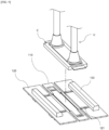
FIG. 2 is a perspective view of a transfer device 1000 according to a first embodiment of the present invention. - The transfer device 1000 of the present invention includes a plurality of
plates 1000a connected to each other, as shown inFIG. 2 . - Each of the
plates 1000a is spaced apart by a predetermined distance and is connected to each other by aseparate connection member 1000b connecting neighboringplates 1000a, as shown inFIG. 2 . - The transfer device 1000 of the present invention includes a seating part in which a battery cell C is seated. More specifically, the transfer device 1000 of the present invention includes a plurality of seating parts spaced apart at predetermined distance, wherein each of the seating part is seated with a battery cell C to be transferred.
- The seating part includes a
center plate 110 on which the battery cell C is seated, asupport plate 120 connected to each side of thecenter plate 110, and a movingbar 150 moving on thesupport plate 120 toward thecenter plate 110 to support the sides of the seated battery cell C. - The battery cell C may be transferred to the seating part with its upper part adsorbed to a suction unit U as shown in
FIG. 2 , and is seated on thecenter plate 110 by movement of the suction unit U. - As described above, the battery cell C seated on the
center plate 110 is transferred in one direction. - The battery cell C seated on the seating part may be seated only on the
center plate 110, or may be seated across thecenter plate 110 andsupport plate 120. - The transfer device 1000 of the present invention may include a plurality of
center plates 110 spaced apart at predetermined distance, wherein the battery cells C seated on eachcenter plate 110 are all transferred in the same direction. - The
support plate 120 serves to guide the battery cell C adsorbed by the suction unit U to the center of thecenter plate 110. More specifically, thesupport plate 120 serves to support the lower part of the movingbar 150 so that the movingbar 150, which moves in the upper part, can reciprocate horizontally. - The moving
bar 150 reciprocates on thesupport plate 120 in a direction toward thecenter plate 110 or against thecenter plate 110. - The moving
bar 150 moves to thecenter plate 110 and serves to align the position of the battery cell C seated on thecenter plate 110 or to pressurize and fix the battery cell C. -
FIG. 3 illustrates a seating part of the transfer device 1000 ofFIG. 2 . - The moving
bar 150 may be formed to extend in a direction orthogonal to the transfer direction, as shown inFIGS. 2 and3 , and the sides of the battery cell C are pressurized or supported by the sides of the extended movingbar 150. - The moving
bar 150 further includes an inclined surface for guiding a battery cell C descending from the upper part to be seated on thecenter plate 110. - As shown in
FIGS. 2 and3 , the inclined surface is formed in a corner part facing thecenter plate 110 among the upper corner parts of the movingbar 150, and extend along the longitudinal direction of the movingbar 150. - The battery cell C descending while being adsorbed by the suction unit U may, in case of misplacement, descend down the inward side of the moving
bar 150 on the inclined surface formed on the movingbar 150 and may be seated on thecenter plate 110. - The moving
bar 150 reciprocates toward thecenter plate 110 to support the sides of the seated battery cell C as shown inFIGS. 2 and3 . More specifically, the movingbar 150 located on both sides of thecenter plate 110 simultaneously move toward thecenter plate 110 on thesupport plate 120 to pressurize the sides of the battery cell C seated on thecenter plate 110. - Thus, the battery cell C, pressurized at the same rate on both sides, is aligned on the
center plate 110 such that the longitudinal direction of the battery cell C is horizontal to both the longitudinal direction of the movingbar 150 and the longitudinal direction of thecenter plate 110. - The moving
bar 150 is capable of reciprocating by an operation of apiston 141 inserted to acylinder body 140. -
FIG. 4 is a bottom perspective view of the seating part ofFIG. 3 . - According to
FIG. 4 , the seating part includes acylinder body 140 with apiston 141 inserted therein, which is provided at the lower part of thesupport plate 120 and moves reciprocally toward thecenter plate 110, and the movingbar 150 is coupled to thepiston 141 and moves reciprocally in response to the operation of thepiston 141. - The seating part of the present invention may further include an
auxiliary plate 130 connected to one of the two sides of thesupport plate 120 opposite thecenter plate 110, in which case thecylinder body 140 is coupled to theauxiliary plate 130. - The
cylinder body 140 is coupled to the lower part of theauxiliary plate 130 as shown inFIGS. 3 and4 , and apiston 141 inserted in thecylinder body 140 reciprocates on the lower part of thesupport plate 120 between theauxiliary plate 130 and thecenter plate 110. - The
support plate 120 includes aguide part 121 extending in the transfer direction as shown inFIGS. 3 and4 , and thepiston 141 moves by being guided by theguide part 121. - The
piston 141 includes at its end acoupling member 160 that penetrates theguide part 121 to be coupled to the movingbar 150, and the movingbar 150 andpiston 141 reciprocate in a path in which thecoupling member 160 is guided by theguide part 121. That is, the movingbar 150 coupled to thepiston 141 by thecoupling member 160 can be moved toward thecenter plate 110 by thecoupling member 160 being guided by theguide part 121. - As the
piston 141 is inserted into thecylinder body 140, the movingbar 150 moves in a direction opposite to thecenter plate 110, and as thepiston 141 protrudes from thecylinder body 140, the movingbar 150 moves toward thecenter plate 110. By such operation of thepiston 141, the movingbar 150 is advanced toward the battery cell C. - The moving
bar 150 may be actuated upon detection by asensor 170. - That is, the seating part included in the transfer device 1000 of the present invention may further include a
sensor 170 that detects an object. - In order to increase the efficiency of the process, the moving
bar 150 is moved by detection of thesensor 170 only after the battery cell C adsorbed by the suction unit U is seated on thecenter plate 110. -
FIG. 5 illustrates asensor 170 applied to a seating part. - The
sensor 170 may preferably be provided on thecenter plate 110, wherein thesensor 170 included in thecenter plate 110 detects whether a battery cell C adsorbed and moved by the suction unit U is seated on the seating part. - The
sensor 170 may be a pressure sensor that senses the weight of the battery cell C, or it may be a light sensor that senses light to detect whether the battery cell C is fully seated on thecenter plate 110. However, thesensor 170 of the present invention need not be limited to the above types, and any type ofsensor 170 that can detect whether the battery cell C is properly seated on thecenter plate 110 is applicable to the transfer device 1000 of the present invention. - The
support plate 120 includes afirst support plate 120a connected to one side of thecenter plate 110, and asecond support plate 120b connected to the other side of thecenter plate 110. - A moving
bar 150 included in thefirst support plate 120a and thesecond support plate 120b move in opposite directions to each other. -
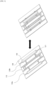
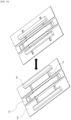
FIGS. 6(a) and(b) through 8 illustrate step-by-step the operation of the transfer device 1000 of the present invention. Specifically,FIG. 6(a) and(b) illustrates a seating part prior to seating the battery cell C,FIG. 7(a) and (b) illustrates a seating part after seating the battery cell C but before aligning the battery cell C, andFIG. 8(a) and (b) illustrates a seating part after aligning the battery cell C. - Referring to
FIG. 6(a) , before the battery cell C adsorbed by the suction unit U descends to the seating part, the movingbar 150 is moved as far as possible in the direction opposite to thecenter plate 110. At this time, referring toFIG. 6(b) , thepiston 141 is fully inserted into thecylinder body 140 and remains in the inserted state. - Referring to
FIG. 7(a) , the battery cell C adsorbed by the suction unit U descends to the seating part and is seated on thecenter plate 110, and at this time, the movingbar 150 is held in the position ofFIG. 6(a) and (b) so that the seating of the battery cell C is not disturbed by the movingbar 150. At this time, thepiston 141 also maintains the position ofFIG. 6(a) and (b) , as shown inFIG. 7(b) . - Referring to
FIG. 8(a) , movingbars 150 on both sides move toward the battery cell C seated on thecenter plate 110 and pressurize the sides of the battery cell C. This causes the battery cell C to be pushed against the movingbars 150 so that its position can be aligned and fixed simultaneously. At this time, thepiston 141 protrudes from thecylinder body 140 as shown inFIG. 8(b) . - The transfer device 1000 of the present invention is installed with a moving
bar 150 that moves horizontally and reciprocally to align and fix the battery cell C on theplate 1000a as described in conjunction with the drawings, so that the process of the battery cell C being seated by the movingbar 150 can be unimpeded, and also has the effect of stably aligning the position, thereby increasing the efficiency of the process. - The cylinder body of the present invention may be coupled directly to the
support plate 120 rather than to theauxiliary plate 130. -
FIG. 9 is a perspective view of a transfer device 1000 according to a second embodiment of the present invention,FIG. 10 is a perspective view of a seating part included in the transfer device 1000 ofFIG. 9 . - The seating part includes a
center plate 110, a pair ofsupport plates 120 connected to both sides of thecenter plate 110, and a movingbar 150 that reciprocates horizontally on thesupport plates 120, as shown inFIGS. 9 and10 . - The
cylinder body 140 is provided at the lower part of thesupport plate 120. - Specifically, the
support plate 120 includes aguide part 121 extending along the transfer direction, and includes acylinder body 140 at the lower part with apiston 141 inserted therein that reciprocates toward thecenter plate 110. - Thus, as shown in
FIG. 9 , when the battery cell C adsorbed by the suction unit U is seated on the upper part of thecenter plate 110, the movement of thepiston 141 of thecylinder body 140 provided in the lower part of thesupport plate 120 causes the movingbar 150 connected with thepiston 141 by acoupling member 160 to move towards thecenter plate 110 so as to pressurize the side of the battery cell C. - The transfer device 1000 according to the second embodiment of the present invention has the effect that more battery cells C can be transferred on the same length of transfer device 1000, since
fewer plates 1000a are required to align and fix the battery cells C. - The present invention has been described in more detail above with reference to the drawings and embodiments. However, it is to be understood that the configurations shown in the drawings or embodiments described herein are only one embodiment of the invention and do not represent all of the technical ideas of the invention, and that there may be various equivalents and modifications that may replace them at the time of filing the present application.
-
- 10: (CONVENTIONAL ART) CONVEYOR
- 20: (CONVENTIONAL ART) PLATE
- 30: (CONVENTIONAL ART) SUPPORT BAR
- 1000: TRANSFER DEVICE
- 1000a: PLATE
- 1000b: CONNECTION MEMBER
- 100: SEATING PART
- 110: CENTER PLATE
- 120: SUPPORT PLATE
- 120a: FIRST SUPPORT PLATE
- 120b: SECOND SUPPORT PLATE
- 121: GUIDE PART
- 130: AUXILIARY PLATE
- 140: CYLINDER BODY
- 141: PISTON
- 150: MOVING BAR
- 160: COUPLING MEMBER
- 170: SENSOR
- U: SUCTION UNIT
- C: BATTERY CELL
Claims (13)
- A transfer device comprising a plurality of interconnected plates, and unidirectionally transferring battery cells by seating them on the plates, comprising:a seating part on which the battery cell is seated, whereinthe seating part comprises:a center plate where a battery cell is seated;a support plate connected to each side of the center plate; anda moving bar moving on the support plate toward the center plate to support the sides of a seated battery cell.
- The transfer device of claim 1, wherein
the seating part further comprises a sensor for detecting an object. - The transfer device of claim 2, whereinthe sensor is provided on the center plate,the sensor provided on the center plate detects that the battery cell is seated on the center plate, andthe moving bar is moved forwardly toward the center plate upon detection by the sensor to pressurize the battery cell.
- The transfer device of claim 1, comprising
a plurality of seating parts spaced apart in predetermined distance. - The transfer device of claim 1, wherein
the support plate comprises:a first support plate connected to one side of the center plate; anda second support plate connected to the other side of the center plate, whereinthe moving bar is provided in a pair, the pair of moving of bars are included in the first support plate and the second support plate and move toward the center plate to support and fix both sides of a battery cell seated on the center plate. - The transfer device of claim 5, wherein
the moving bar included in the first support plate and the second support plate moves in opposite directions to each other. - The transfer device of claim 1, wherein
the seating part includes a cylinder body provided at a lower part of the support plate, with a piston inserted therein reciprocating toward the center plate. - The transfer device of claim 7, whereinthe support plate includes a guide part extending in the transfer direction,the piston includes a coupling member, which passes through the guide part and couples to the moving bar, at an end, whereina moving bar coupled to the piston is moved toward the center plate by the coupling member guided by the guide part.
- The transfer device of claim 1, whereinthe seating part further comprisesan auxiliary plate connected to one side of the support plate that is opposite the center plate, whereinthe seating part includes a cylinder body provided at a lower part of the auxiliary plate, with a piston inserted therein reciprocating toward the center plate.
- The transfer device of claim 9, whereinthe support plate includes a guide part extending in the transfer direction,the piston includes a coupling member, which passes through the guide part and couples to the moving bar, at an end, whereinthe moving bar coupled to the piston is moved toward the center plate by the coupling member guided by the guide part.
- The transfer device of claim 1, wherein
the moving bar is formed by extending in a direction orthogonal to the transfer direction. - The transfer device of claim 1, wherein
the moving bar includes an inclined surface at an upper corner part facing the center plate. - The transfer device of claim 1, further comprising
a connection member connecting the neighboring pair of plates.
Applications Claiming Priority (2)
| Application Number | Priority Date | Filing Date | Title |
|---|---|---|---|
| KR1020220108576A KR102966113B1 (en) | 2022-08-29 | Conveying device | |
| PCT/KR2023/012698 WO2024049129A1 (en) | 2022-08-29 | 2023-08-28 | Transfer device |
Publications (2)
| Publication Number | Publication Date |
|---|---|
| EP4556410A1 true EP4556410A1 (en) | 2025-05-21 |
| EP4556410A4 EP4556410A4 (en) | 2026-03-04 |
Family
ID=90098235
Family Applications (1)
| Application Number | Title | Priority Date | Filing Date |
|---|---|---|---|
| EP23860805.3A Pending EP4556410A4 (en) | 2022-08-29 | 2023-08-28 | TRANSFER DEVICE |
Country Status (5)
| Country | Link |
|---|---|
| US (1) | US20250183349A1 (en) |
| EP (1) | EP4556410A4 (en) |
| JP (1) | JP7753608B2 (en) |
| CN (1) | CN118804883A (en) |
| WO (1) | WO2024049129A1 (en) |
Family Cites Families (14)
| Publication number | Priority date | Publication date | Assignee | Title |
|---|---|---|---|---|
| JPS6093616U (en) * | 1983-11-30 | 1985-06-26 | ナショナル住宅産業株式会社 | Conveyance device |
| JPS6134518U (en) * | 1984-07-31 | 1986-03-03 | 澁谷工業株式会社 | Container conveyance device |
| KR900006970Y1 (en) * | 1987-09-21 | 1990-08-04 | 대우중공업 주식회사 | Automatic clamping device for pallet of manless carriage |
| AT393336B (en) * | 1989-06-07 | 1991-09-25 | Jungfer Akkumulatoren | DEVICE FOR SETTING BATTERY PANELS |
| JPH03125717U (en) * | 1990-03-29 | 1991-12-19 | ||
| JP2553999B2 (en) * | 1992-01-20 | 1996-11-13 | 株式会社フジキカイ | Method and device for side-by-side conveyance of articles |
| KR101442956B1 (en) * | 2013-02-06 | 2014-09-23 | 김경범 | feeding chain for root vegetables cutting machine |
| KR20150026316A (en) | 2013-09-02 | 2015-03-11 | 주식회사 엘지화학 | Dust removable conveyor |
| JP6816604B2 (en) | 2017-03-28 | 2021-01-20 | 株式会社豊田自動織機 | Electrode transfer device |
| CN111370778A (en) * | 2020-03-18 | 2020-07-03 | 长兴水木机电有限公司 | Storage battery pole group processing production line |
| CN111952656A (en) * | 2020-08-12 | 2020-11-17 | 天能电池集团股份有限公司 | Automatic installation device for storage battery leather cap |
| KR102475902B1 (en) | 2021-01-27 | 2022-12-22 | 한경수 | Construction method of functional reinforcement boundary stone and its construction method using waste materials |
| CN215796648U (en) * | 2021-09-30 | 2022-02-11 | 河北电机股份有限公司 | Part blanking device |
| CN216862659U (en) | 2021-12-31 | 2022-07-01 | 深圳市镭煜科技有限公司 | High compatible adjustable link joint structure |
-
2023
- 2023-08-28 WO PCT/KR2023/012698 patent/WO2024049129A1/en not_active Ceased
- 2023-08-28 CN CN202380024981.0A patent/CN118804883A/en active Pending
- 2023-08-28 JP JP2024552239A patent/JP7753608B2/en active Active
- 2023-08-28 US US18/845,077 patent/US20250183349A1/en active Pending
- 2023-08-28 EP EP23860805.3A patent/EP4556410A4/en active Pending
Also Published As
| Publication number | Publication date |
|---|---|
| WO2024049129A1 (en) | 2024-03-07 |
| EP4556410A4 (en) | 2026-03-04 |
| KR20240030044A (en) | 2024-03-07 |
| JP7753608B2 (en) | 2025-10-15 |
| WO2024049129A9 (en) | 2024-05-23 |
| CN118804883A (en) | 2024-10-18 |
| US20250183349A1 (en) | 2025-06-05 |
| JP2025506981A (en) | 2025-03-13 |
Similar Documents
| Publication | Publication Date | Title |
|---|---|---|
| KR102015898B1 (en) | Folding Device for electrode lead Part of Battery Cell | |
| CN108496271B (en) | Electrode stacking device and electrode stacking method | |
| JP5746899B2 (en) | Battery assembly system, battery element positioning and conveying device | |
| US10205143B2 (en) | Battery pack | |
| JP5946648B2 (en) | Battery cell transfer system | |
| EP2858163A1 (en) | Meandering correction device for electrode assembly | |
| US20250183349A1 (en) | Transfer Device | |
| US20240069119A1 (en) | Voltage detection device and battery module | |
| CN118387596A (en) | Automatic feeding and discharging equipment for soft-package cylindrical lithium battery and production line of automatic feeding and discharging equipment | |
| CN109937492A (en) | The manufacturing device and its method of multi items lid assembly | |
| KR102536551B1 (en) | Degassing device for manufacturing secondary battery | |
| KR102966113B1 (en) | Conveying device | |
| KR20210097903A (en) | Gripper for charging and discharging of pouch type battery, and charging and discharging device of pouch type battery having same | |
| US12531262B2 (en) | Suction apparatus | |
| KR20180049450A (en) | Device of manufacturing simultaneously cap-assemblies | |
| KR20250081783A (en) | Battery module | |
| CN219620262U (en) | Conveying structure and battery cell production line | |
| EP4254577A1 (en) | Secondary battery manufacturing system and manufacturing method | |
| CN209389155U (en) | A kind of battery clamp device | |
| JP2018012603A (en) | Lamination device | |
| KR102197509B1 (en) | Algin apparatus of system for producing electrodes of battery | |
| KR101490982B1 (en) | Apparatus for attaching heat sink, heat sink attachment module | |
| KR20220129385A (en) | A jig for seating a battery cell without damage and An apparatus for array of battery cells, and inserting method a battery cell into the jig | |
| KR102882246B1 (en) | Secondary battery transfer device | |
| EP4693540A1 (en) | Battery manufacturing apparatus and method |
Legal Events
| Date | Code | Title | Description |
|---|---|---|---|
| STAA | Information on the status of an ep patent application or granted ep patent |
Free format text: STATUS: THE INTERNATIONAL PUBLICATION HAS BEEN MADE |
|
| PUAI | Public reference made under article 153(3) epc to a published international application that has entered the european phase |
Free format text: ORIGINAL CODE: 0009012 |
|
| STAA | Information on the status of an ep patent application or granted ep patent |
Free format text: STATUS: REQUEST FOR EXAMINATION WAS MADE |
|
| 17P | Request for examination filed |
Effective date: 20240826 |
|
| AK | Designated contracting states |
Kind code of ref document: A1 Designated state(s): AL AT BE BG CH CY CZ DE DK EE ES FI FR GB GR HR HU IE IS IT LI LT LU LV MC ME MK MT NL NO PL PT RO RS SE SI SK SM TR |
|
| DAV | Request for validation of the european patent (deleted) | ||
| DAX | Request for extension of the european patent (deleted) | ||
| A4 | Supplementary search report drawn up and despatched |
Effective date: 20260130 |
|
| RIC1 | Information provided on ipc code assigned before grant |
Ipc: B65G 17/46 20060101AFI20260126BHEP Ipc: B65G 17/40 20060101ALI20260126BHEP Ipc: B65G 17/08 20060101ALI20260126BHEP Ipc: H01M 50/20 20210101ALI20260126BHEP Ipc: H01M 10/04 20060101ALI20260126BHEP Ipc: H01M 50/105 20210101ALI20260126BHEP Ipc: B65G 47/91 20060101ALI20260126BHEP |