EP4556313A1 - Flexible warning light - Google Patents
Flexible warning light Download PDFInfo
- Publication number
- EP4556313A1 EP4556313A1 EP23210651.8A EP23210651A EP4556313A1 EP 4556313 A1 EP4556313 A1 EP 4556313A1 EP 23210651 A EP23210651 A EP 23210651A EP 4556313 A1 EP4556313 A1 EP 4556313A1
- Authority
- EP
- European Patent Office
- Prior art keywords
- light
- heat sink
- flexible
- base
- warning light
- Prior art date
- Legal status (The legal status is an assumption and is not a legal conclusion. Google has not performed a legal analysis and makes no representation as to the accuracy of the status listed.)
- Pending
Links
Images


Classifications
-
- B—PERFORMING OPERATIONS; TRANSPORTING
- B60—VEHICLES IN GENERAL
- B60Q—ARRANGEMENT OF SIGNALLING OR LIGHTING DEVICES, THE MOUNTING OR SUPPORTING THEREOF OR CIRCUITS THEREFOR, FOR VEHICLES IN GENERAL
- B60Q1/00—Arrangement of optical signalling or lighting devices, the mounting or supporting thereof or circuits therefor
- B60Q1/26—Arrangement of optical signalling or lighting devices, the mounting or supporting thereof or circuits therefor the devices being primarily intended to indicate the vehicle, or parts thereof, or to give signals, to other traffic
- B60Q1/2615—Arrangement of optical signalling or lighting devices, the mounting or supporting thereof or circuits therefor the devices being primarily intended to indicate the vehicle, or parts thereof, or to give signals, to other traffic mounted on the vehicle body, e.g. with magnets
-
- B—PERFORMING OPERATIONS; TRANSPORTING
- B60—VEHICLES IN GENERAL
- B60Q—ARRANGEMENT OF SIGNALLING OR LIGHTING DEVICES, THE MOUNTING OR SUPPORTING THEREOF OR CIRCUITS THEREFOR, FOR VEHICLES IN GENERAL
- B60Q1/00—Arrangement of optical signalling or lighting devices, the mounting or supporting thereof or circuits therefor
- B60Q1/26—Arrangement of optical signalling or lighting devices, the mounting or supporting thereof or circuits therefor the devices being primarily intended to indicate the vehicle, or parts thereof, or to give signals, to other traffic
- B60Q1/2619—Arrangement of optical signalling or lighting devices, the mounting or supporting thereof or circuits therefor the devices being primarily intended to indicate the vehicle, or parts thereof, or to give signals, to other traffic built in the vehicle body
- B60Q1/2623—Details of the fastening means
- B60Q1/2626—Screw-nut fasteners
-
- B—PERFORMING OPERATIONS; TRANSPORTING
- B60—VEHICLES IN GENERAL
- B60Q—ARRANGEMENT OF SIGNALLING OR LIGHTING DEVICES, THE MOUNTING OR SUPPORTING THEREOF OR CIRCUITS THEREFOR, FOR VEHICLES IN GENERAL
- B60Q1/00—Arrangement of optical signalling or lighting devices, the mounting or supporting thereof or circuits therefor
- B60Q1/26—Arrangement of optical signalling or lighting devices, the mounting or supporting thereof or circuits therefor the devices being primarily intended to indicate the vehicle, or parts thereof, or to give signals, to other traffic
- B60Q1/2619—Arrangement of optical signalling or lighting devices, the mounting or supporting thereof or circuits therefor the devices being primarily intended to indicate the vehicle, or parts thereof, or to give signals, to other traffic built in the vehicle body
- B60Q1/2638—Positioning the device housing by indexing means separate from the fastening means, e.g. pins, rails
-
- B—PERFORMING OPERATIONS; TRANSPORTING
- B60—VEHICLES IN GENERAL
- B60Q—ARRANGEMENT OF SIGNALLING OR LIGHTING DEVICES, THE MOUNTING OR SUPPORTING THEREOF OR CIRCUITS THEREFOR, FOR VEHICLES IN GENERAL
- B60Q1/00—Arrangement of optical signalling or lighting devices, the mounting or supporting thereof or circuits therefor
- B60Q1/26—Arrangement of optical signalling or lighting devices, the mounting or supporting thereof or circuits therefor the devices being primarily intended to indicate the vehicle, or parts thereof, or to give signals, to other traffic
- B60Q1/2619—Arrangement of optical signalling or lighting devices, the mounting or supporting thereof or circuits therefor the devices being primarily intended to indicate the vehicle, or parts thereof, or to give signals, to other traffic built in the vehicle body
- B60Q1/2653—Arrangement of optical signalling or lighting devices, the mounting or supporting thereof or circuits therefor the devices being primarily intended to indicate the vehicle, or parts thereof, or to give signals, to other traffic built in the vehicle body with arrangement for sealing the device with respect to the vehicle body, or for concealing gaps between the device and the vehicle body
-
- F—MECHANICAL ENGINEERING; LIGHTING; HEATING; WEAPONS; BLASTING
- F21—LIGHTING
- F21S—NON-PORTABLE LIGHTING DEVICES; SYSTEMS THEREOF; VEHICLE LIGHTING DEVICES SPECIALLY ADAPTED FOR VEHICLE EXTERIORS
- F21S43/00—Signalling devices specially adapted for vehicle exteriors, e.g. brake lamps, direction indicator lights or reversing lights
- F21S43/10—Signalling devices specially adapted for vehicle exteriors, e.g. brake lamps, direction indicator lights or reversing lights characterised by the light source
- F21S43/13—Signalling devices specially adapted for vehicle exteriors, e.g. brake lamps, direction indicator lights or reversing lights characterised by the light source characterised by the type of light source
- F21S43/14—Light emitting diodes [LED]
-
- F—MECHANICAL ENGINEERING; LIGHTING; HEATING; WEAPONS; BLASTING
- F21—LIGHTING
- F21S—NON-PORTABLE LIGHTING DEVICES; SYSTEMS THEREOF; VEHICLE LIGHTING DEVICES SPECIALLY ADAPTED FOR VEHICLE EXTERIORS
- F21S43/00—Signalling devices specially adapted for vehicle exteriors, e.g. brake lamps, direction indicator lights or reversing lights
- F21S43/10—Signalling devices specially adapted for vehicle exteriors, e.g. brake lamps, direction indicator lights or reversing lights characterised by the light source
- F21S43/13—Signalling devices specially adapted for vehicle exteriors, e.g. brake lamps, direction indicator lights or reversing lights characterised by the light source characterised by the type of light source
- F21S43/15—Strips of light sources
-
- F—MECHANICAL ENGINEERING; LIGHTING; HEATING; WEAPONS; BLASTING
- F21—LIGHTING
- F21S—NON-PORTABLE LIGHTING DEVICES; SYSTEMS THEREOF; VEHICLE LIGHTING DEVICES SPECIALLY ADAPTED FOR VEHICLE EXTERIORS
- F21S43/00—Signalling devices specially adapted for vehicle exteriors, e.g. brake lamps, direction indicator lights or reversing lights
- F21S43/10—Signalling devices specially adapted for vehicle exteriors, e.g. brake lamps, direction indicator lights or reversing lights characterised by the light source
- F21S43/19—Attachment of light sources or lamp holders
- F21S43/195—Details of lamp holders, terminals or connectors
-
- F—MECHANICAL ENGINEERING; LIGHTING; HEATING; WEAPONS; BLASTING
- F21—LIGHTING
- F21S—NON-PORTABLE LIGHTING DEVICES; SYSTEMS THEREOF; VEHICLE LIGHTING DEVICES SPECIALLY ADAPTED FOR VEHICLE EXTERIORS
- F21S43/00—Signalling devices specially adapted for vehicle exteriors, e.g. brake lamps, direction indicator lights or reversing lights
- F21S43/20—Signalling devices specially adapted for vehicle exteriors, e.g. brake lamps, direction indicator lights or reversing lights characterised by refractors, transparent cover plates, light guides or filters
- F21S43/265—Transparent cover plates, e.g. for protecting the interior of the signalling devices against environmental influences
-
- F—MECHANICAL ENGINEERING; LIGHTING; HEATING; WEAPONS; BLASTING
- F21—LIGHTING
- F21S—NON-PORTABLE LIGHTING DEVICES; SYSTEMS THEREOF; VEHICLE LIGHTING DEVICES SPECIALLY ADAPTED FOR VEHICLE EXTERIORS
- F21S43/00—Signalling devices specially adapted for vehicle exteriors, e.g. brake lamps, direction indicator lights or reversing lights
- F21S43/20—Signalling devices specially adapted for vehicle exteriors, e.g. brake lamps, direction indicator lights or reversing lights characterised by refractors, transparent cover plates, light guides or filters
- F21S43/27—Attachment thereof
-
- F—MECHANICAL ENGINEERING; LIGHTING; HEATING; WEAPONS; BLASTING
- F21—LIGHTING
- F21S—NON-PORTABLE LIGHTING DEVICES; SYSTEMS THEREOF; VEHICLE LIGHTING DEVICES SPECIALLY ADAPTED FOR VEHICLE EXTERIORS
- F21S43/00—Signalling devices specially adapted for vehicle exteriors, e.g. brake lamps, direction indicator lights or reversing lights
- F21S43/20—Signalling devices specially adapted for vehicle exteriors, e.g. brake lamps, direction indicator lights or reversing lights characterised by refractors, transparent cover plates, light guides or filters
- F21S43/281—Materials thereof; Structures thereof; Properties thereof; Coatings thereof
- F21S43/2815—Mechanical properties, e.g. flexibility
-
- F—MECHANICAL ENGINEERING; LIGHTING; HEATING; WEAPONS; BLASTING
- F21—LIGHTING
- F21S—NON-PORTABLE LIGHTING DEVICES; SYSTEMS THEREOF; VEHICLE LIGHTING DEVICES SPECIALLY ADAPTED FOR VEHICLE EXTERIORS
- F21S45/00—Arrangements within vehicle lighting devices specially adapted for vehicle exteriors, for purposes other than emission or distribution of light
-
- F—MECHANICAL ENGINEERING; LIGHTING; HEATING; WEAPONS; BLASTING
- F21—LIGHTING
- F21S—NON-PORTABLE LIGHTING DEVICES; SYSTEMS THEREOF; VEHICLE LIGHTING DEVICES SPECIALLY ADAPTED FOR VEHICLE EXTERIORS
- F21S45/00—Arrangements within vehicle lighting devices specially adapted for vehicle exteriors, for purposes other than emission or distribution of light
- F21S45/40—Cooling of lighting devices
- F21S45/47—Passive cooling, e.g. using fins, thermal conductive elements or openings
-
- F—MECHANICAL ENGINEERING; LIGHTING; HEATING; WEAPONS; BLASTING
- F21—LIGHTING
- F21S—NON-PORTABLE LIGHTING DEVICES; SYSTEMS THEREOF; VEHICLE LIGHTING DEVICES SPECIALLY ADAPTED FOR VEHICLE EXTERIORS
- F21S45/00—Arrangements within vehicle lighting devices specially adapted for vehicle exteriors, for purposes other than emission or distribution of light
- F21S45/40—Cooling of lighting devices
- F21S45/47—Passive cooling, e.g. using fins, thermal conductive elements or openings
- F21S45/48—Passive cooling, e.g. using fins, thermal conductive elements or openings with means for conducting heat from the inside to the outside of the lighting devices, e.g. with fins on the outer surface of the lighting device
-
- F—MECHANICAL ENGINEERING; LIGHTING; HEATING; WEAPONS; BLASTING
- F21—LIGHTING
- F21S—NON-PORTABLE LIGHTING DEVICES; SYSTEMS THEREOF; VEHICLE LIGHTING DEVICES SPECIALLY ADAPTED FOR VEHICLE EXTERIORS
- F21S45/00—Arrangements within vehicle lighting devices specially adapted for vehicle exteriors, for purposes other than emission or distribution of light
- F21S45/50—Waterproofing
Definitions
- the present invention relates to a flexible warning light, in particular to a lamp shell made of a flexible material that is positioned on a curved surface of a vehicle body to be installed and then elastically deforms, thereby driving a first heat sink and at least one second heat sink in the base to deform, so that the base can be closely attached to the curved surface of the vehicle body to be installed to achieve the effect of being more compliant with the curved vehicle body.
- the present invention has been accomplished under the circumstances in view. It is the main object of the present invention to provide a flexible warning light, which comprises: a lamp housing and a light-emitting device.
- the lamp housing comprises a base, a lamp shell, and an accommodation space defined between the base and the lamp shell.
- the base comprises a bottom plate.
- the lamp shell is made of a flexible material and covered on the base.
- the light-emitting device is mounted in the accommodation space.
- the light-emitting device comprises a flexible circuit board with at least one light-emitting element mounted on the flexible circuit board, and a first heat sink and at least one second heat sink provided on a bottom side of the flexible circuit board.
- the lamp shell made of a flexible material is elastically deformable in accordance with the surface curvature of a preset vehicle body to drive the first heat sink and the at least one second heat sink to deform, thereby fitting the base on the surface of the preset vehicle body.
- the first heat sink of the light-emitting device comprises a first wire hole for a plurality of predetermined wires to pass through and a plurality of reinforcement ribs protruding from two sides surfaces of the first wire hole for structural reinforcement;
- the at least one second heat sink of the light-emitting device each comprises a second wire hole corresponding to the first wire hole, and a plurality of grooves recessed on two opposite sides thereof for accommodating the reinforcement ribs. This further strengthens the structure to prevent the first heat sink and the at least one second heat sink from breaking when the lamp housing is bent.
- the bottom plate of the base comprises a through hole for a plurality of predetermined wires to pass through;
- the flexible circuit board of the light-emitting device is provided with a plurality of positioning holes for the predetermined wires to pass through and position;
- the base comprises a positioning sleeve protruding from the bottom surface of the bottom plate around the periphery of the through hole of the bottom plate, at least one limiting block protruded from one side of the positioning sleeve, and a buffer pad assembled with the bottom surface of the bottom plate.
- the buffer pad comprises two notches respectively located on two opposite sides, an alignment hole sleeved on the positioning sleeve, and a limiting hole extended from at least one side of the alignment hole to accommodate the at least one limiting block respectively.
- the lamp shell comprises a main body, and at least one lampshade mounted in the main body and covering said at least one light-emitting element on the flexible circuit board; the lamp shell further comprises a plurality of positioning bumps provided on at least two sides inside main body and resisted against the surface of said flexible circuit board, and a sealing flange was provided on the inner edge of said main body to fit and surround the periphery of the bottom plate.
- the flexible warning light of the present invention mainly comprises a lamp housing 1 and a light-emitting device 2 .
- the connection relationship between the aforementioned components is as follows:
- the lamp housing 1 comprises a base 11 and a lamp shell 12 , and an accommodation space 10 is provided between the base 11 and the lamp shell 12 .
- the base 11 is made of metal.
- the base 11 comprises a penetrated bottom plate 111 provided with a through hole 1110 for a plurality of wires 3 to pass through, a convex plate 1111 extending upward from the periphery of the bottom plate 111 and inserted into the lamp shell 12 , a positioning sleeve 1112 protruding from the bottom surface of the bottom plate 111 around the periphery of the through hole 1110 , at least one limiting block 1113 protruded from the positioning sleeve 1112 , and a buffer pad 13 assembled with the bottom surface of the bottom plate 111 .
- the buffer pad 13 concavely comprises two notches 131 respectively located on both sides, an alignment hole 130 sleeved on the positioning sleeve 1112 , and at least one limiting hole 1301 extended from at least one side of the alignment hole 130 to corresponds to accommodate the at least one limiting block 1113 respectively.
- the lamp shell 12 is made of a flexible material, and the lamp shell 12 comprises a main body 121 , at least one lampshade 1211 mounted in the main body 121 , and a plurality of mounts 122 located on at least two sides of the main body 121 for assembling on the vehicle to be installed.
- the light-emitting device 2 is assembled in the accommodation space 10 between the base 11 and the lamp shell 12 .
- the light-emitting device 2 comprises a flexible circuit board 21 provided with at least one light-emitting element 211 corresponding to the position of the at least one lampshade 1211 in the main body 121 and a plurality of positioning holes 210 for the wires 3 to pass through and set, and a first heat sink 22 and the at least one second heat sink 23 provided on the bottom side of the flexible circuit board 21 .
- the first heat sink 22 is provided with a first wire hole 220 for the wires 3 to pass through, and reinforcement ribs 221 with a reinforced structure protruding from both side surfaces of the first wire hole 220 of the first heat sink 22 .
- Each of the at least one second heat sink 23 is provided with a second wire hole 230 corresponding to the first wire hole 220 , and grooves 231 for accommodating the reinforcement ribs 221 are recessed on both sides of the second heat sink 23 .
- the wires 3 to be installed in the vehicle body are first passed through the alignment hole 130 of the buffer pad 13 , the through hole 1110 of the bottom plate 111 , the first wire hole 220 of the first heat sink 22 , and the second wire hole 230 of the second heat sink in sequence, and then positioned in the positioning holes 210 of the flexible circuit board 21 to form electrical connections with the flexible circuit board 21 .
- the base 11 cover the lamp shell 12 so that the light-emitting device 2 is located in the accommodation space 10 , and the positioning bumps 14 provided on at least two sides inside the lamp housing 1 will resist the surface of the flexible circuit board 21 , and then push the flexible circuit board 21 downward to press the first heat sink 22 and the at least one second heat sink 23 against the surface of the bottom plate 111 to form a position.
- the at least one lampshade 1211 in the lamp shell 12 will cover the at least one light-emitting element 211 on the flexible circuit board 21 to guide light refraction, and the mounts 122 on at least two sides of the main body 121 of the lamp shell 12 will be positioned on the surface of the vehicle body to be installed.
- the lamp shell 12 of the lamp housing 1 is made of a flexible material, after the two mounts 122 are positioned, the lamp shell 12 will elastically deform in accordance with the surface curvature of the vehicle body to be installed to drive the first heat sink 22 and the at least one second heat sink 23 to deform. Then, the base 11 is deformed by the influence of the first heat sink 22 and the at least one second heat sink 23 inside, so that the base 11 can closely contact the surface of the vehicle body to be installed. This completes the installation of the overall structure of the flexible warning light of the present invention.
- FIGS. 3 to 5 Please continue to refer to FIGS. 3 to 5 . It can be clearly seen from the FIGS. that the first heat sink 22 and the at least one second heat sink 23 that are located between the base 11 and the lamp shell 12 and are attached to the flexible circuit board 21 will dissipate heat when the flexible circuit board 21 is operating.
- the quantity of the at least one second heat sink 23 can be adjusted according to the heat dissipation requirement of the flexible circuit board 21 .
- the heat energy is transferred through the integrated structural surfaces of the first heat sink 22 and the at least one second heat sink 23 to reduce the heat accumulation inside the heat sink, and the base 11 made of metal is used to increase the transfer of heat energy to achieve more effective heat dissipation.
- the grooves 231 on both sides of the at least one second heat sink 23 will be sleeved on the two reinforcement ribs 221 protruding on the surface of the first heat sink 22 to form a structural reinforcement, thereby preventing the first heat sink 22 and the at least one second heat sink 23 from breaking when the lamp housing 1 is bent.
- the thickness of the above-mentioned first heat sink 22 and the at least one second heat sink 23 is each respectively between 0.1mm ⁇ 1.5mm. In a preferred implementation, the thickness of the first heat sink 22 and the at least one second heat sink 23 is each respectively between 0.2mm and 0.8mm. It uses multiple heat sinks to increase the bending feel and is easier to bend than a single heat sink.
- the base 11 of the lamp housing 1 is made of metal.
- the base 11 can also be made of silicone or plastic material that can deform in conjunction with the lamp shell 12 .
- Such simple equivalent changes and modifications do not limit the scope of protection of the present invention and are hereby stated.
- the at least one lampshade 1211 provided in the main body 121 is in the shape of a square frame, a spherical shape, or other shapes that has the function of covering the at least one light-emitting element 211 and are hereby stated.
- the inner edge of the main body 121 of the lamp shell 12 is provided with a sealing flange 1212 that fits and surrounds the periphery of the bottom plate 111 to form a seal and achieve waterproof and dustproof effects.
- the at least two fasteners 4 in this embodiment each have a head 41 , and a stem 411 with a smaller outer diameter extends downward from the head 41 , and inside the fixing holes 1220 of the mount 122 each are provided with a cap 42 for the stem 411 to be worn and fixed.
- the stems 411 will orderly pass through the fixing holes 1220 and the notches 131 of the buffer pad 13 in order and be positioned on the surface of the vehicle body to be installed.
- flip covers 1221 are respectively assembled to the fixing holes 1220 , thereby achieving the effect of firmly fixing the flexible warning light of the present invention.
- FIG. 6 is very similar to the structure disclosed in FIGS. 1 to 5 , and the only difference is that the positioning sleeve 1112 protruding from the bottom side of the bottom plate 111 is not provided with the at least one limiting block 1113 , and the buffer pad 13 is only provided with the alignment hole 130 for the positioning sleeve 1112 to pass through, and the two sides of the buffer pad 13 are provided with through holes 132 for the stems 411 of the fasteners 4 to pass through, so that the fasteners 4 can pass through the buffer pad 13 and be fixed on the surface of the vehicle body to be installed.
- the remaining structures disclosed in this embodiment are the same as those in FIGS. 1 , 2 , 3 , 4 , and 5 , so they will not be described again here.
- the present invention mainly uses the lamp shell 12 made of a flexible material positioned on the curved surface of the vehicle body to be installed and elastically deforms to drive the first heat sink 22 and the at least one second heat sink 23 to deform, so that the base 11 is deformed by the first heat sink 22 and the at least one second heat sink 23 and closely contacts the curved surface of the vehicle body to be installed, so as to achieve the effect of being more compliant with the curved vehicle body.
Landscapes
- Engineering & Computer Science (AREA)
- General Engineering & Computer Science (AREA)
- Mechanical Engineering (AREA)
- Physics & Mathematics (AREA)
- Microelectronics & Electronic Packaging (AREA)
- Optics & Photonics (AREA)
- Arrangement Of Elements, Cooling, Sealing, Or The Like Of Lighting Devices (AREA)
- Fastening Of Light Sources Or Lamp Holders (AREA)
- Non-Portable Lighting Devices Or Systems Thereof (AREA)
Abstract
A flexible warning light includes a lamp housing (1) including a base (11) with a bottom plate (111), a flexible lamp shell (12) covering the base (11) and an accommodation space (10) defined between the base (11) and the flexible lamp shell (12), and a light-emitting device (2) mounted in the accommodation space (10) and having at least one light-emitting element (211) on the top of a flexible circuit board (21) of a light-emitting device (2) on the top, and a first heat sink (22) and multiple second heat sinks (23) on the bottom. The flexible lamp shell (12) will elastically deform in accordance with the surface curvature of a preset vehicle body to drive the first heat sink (22) and the second heat sinks (23) to deform so that the base (11) can be closely attached to the curved surface of the preset vehicle body through the deformation of the first heat sink (22) and the second heat sinks (23), so as to achieve the effect of being more compliant with the curved vehicle body.
Description
- The present invention relates to a flexible warning light, in particular to a lamp shell made of a flexible material that is positioned on a curved surface of a vehicle body to be installed and then elastically deforms, thereby driving a first heat sink and at least one second heat sink in the base to deform, so that the base can be closely attached to the curved surface of the vehicle body to be installed to achieve the effect of being more compliant with the curved vehicle body.
- Today's electric vehicles are mostly designed with curved surfaces. The current warning lights have a rigid structure and cannot be installed snugly on curved vehicles. If a hard warning light is forcibly installed on the curved surface of an electric vehicle, it will cause the warning light to be unstable or even fall off the surface of the vehicle body, causing the warning light to malfunction. This is the key point that those engaged in this industry urgently want to study and improve.
- The present invention has been accomplished under the circumstances in view. It is the main object of the present invention to provide a flexible warning light, which comprises: a lamp housing and a light-emitting device. The lamp housing comprises a base, a lamp shell, and an accommodation space defined between the base and the lamp shell. The base comprises a bottom plate. The lamp shell is made of a flexible material and covered on the base. The light-emitting device is mounted in the accommodation space. The light-emitting device comprises a flexible circuit board with at least one light-emitting element mounted on the flexible circuit board, and a first heat sink and at least one second heat sink provided on a bottom side of the flexible circuit board. The lamp shell made of a flexible material is elastically deformable in accordance with the surface curvature of a preset vehicle body to drive the first heat sink and the at least one second heat sink to deform, thereby fitting the base on the surface of the preset vehicle body.
- It is another object of the present invention to provide a flexible warning light, wherein the first heat sink of the light-emitting device comprises a first wire hole for a plurality of predetermined wires to pass through and a plurality of reinforcement ribs protruding from two sides surfaces of the first wire hole for structural reinforcement; the at least one second heat sink of the light-emitting device each comprises a second wire hole corresponding to the first wire hole, and a plurality of grooves recessed on two opposite sides thereof for accommodating the reinforcement ribs. This further strengthens the structure to prevent the first heat sink and the at least one second heat sink from breaking when the lamp housing is bent.
- It is still another object of the present invention to provide a flexible warning light, wherein the bottom plate of the base comprises a through hole for a plurality of predetermined wires to pass through; the flexible circuit board of the light-emitting device is provided with a plurality of positioning holes for the predetermined wires to pass through and position; the base comprises a positioning sleeve protruding from the bottom surface of the bottom plate around the periphery of the through hole of the bottom plate, at least one limiting block protruded from one side of the positioning sleeve, and a buffer pad assembled with the bottom surface of the bottom plate. The buffer pad comprises two notches respectively located on two opposite sides, an alignment hole sleeved on the positioning sleeve, and a limiting hole extended from at least one side of the alignment hole to accommodate the at least one limiting block respectively.
- It is still another object of the present invention to provide a flexible warning light, wherein the base of the lamp housing is made of metal.
- It is still another object of the present invention to provide a flexible warning light, wherein the base of the lamp housing is made of silicone material.
- It is still another object of the present invention to provide a flexible warning light, wherein the base further comprises a convex plate extending upward from the periphery of the bottom plate and inserted into the lamp shell.
- It is still another object of the present invention to provide a flexible warning light, wherein the lamp shell comprises a main body, and at least one lampshade mounted in the main body and covering said at least one light-emitting element on the flexible circuit board; the lamp shell further comprises a plurality of positioning bumps provided on at least two sides inside main body and resisted against the surface of said flexible circuit board, and a sealing flange was provided on the inner edge of said main body to fit and surround the periphery of the bottom plate.
-
-
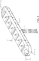
FIG. 1 is a three-dimensional appearance view of the present invention. -
FIG. 2 is a three-dimensional appearance view of the present invention from another perspective. -
FIG. 3 is a three-dimensional exploded view of the present invention. -
FIG. 4 is an exploded three-dimensional view of the present invention from another perspective. -
FIG. 5 is a side cross-sectional view of the present invention. -
FIG. 6 is a three-dimensional appearance view of another embodiment of the present invention. - Please refer to
FIGS. 1 to 5 . The flexible warning light of the present invention mainly comprises alamp housing 1 and a light-emitting device 2. The connection relationship between the aforementioned components is as follows:
Thelamp housing 1 comprises abase 11 and alamp shell 12, and anaccommodation space 10 is provided between thebase 11 and thelamp shell 12. Thebase 11 is made of metal. Thebase 11 comprises apenetrated bottom plate 111 provided with athrough hole 1110 for a plurality ofwires 3 to pass through, aconvex plate 1111 extending upward from the periphery of thebottom plate 111 and inserted into thelamp shell 12, apositioning sleeve 1112 protruding from the bottom surface of thebottom plate 111 around the periphery of the throughhole 1110, at least one limitingblock 1113 protruded from thepositioning sleeve 1112, and abuffer pad 13 assembled with the bottom surface of thebottom plate 111. Thebuffer pad 13 concavely comprises twonotches 131 respectively located on both sides, analignment hole 130 sleeved on thepositioning sleeve 1112, and at least one limitinghole 1301 extended from at least one side of thealignment hole 130 to corresponds to accommodate the at least one limitingblock 1113 respectively. - The
lamp shell 12 is made of a flexible material, and thelamp shell 12 comprises amain body 121, at least onelampshade 1211 mounted in themain body 121, and a plurality ofmounts 122 located on at least two sides of themain body 121 for assembling on the vehicle to be installed. - The light-
emitting device 2 is assembled in theaccommodation space 10 between thebase 11 and thelamp shell 12. The light-emitting device 2 comprises aflexible circuit board 21 provided with at least one light-emittingelement 211 corresponding to the position of the at least onelampshade 1211 in themain body 121 and a plurality ofpositioning holes 210 for thewires 3 to pass through and set, and afirst heat sink 22 and the at least onesecond heat sink 23 provided on the bottom side of theflexible circuit board 21. Thefirst heat sink 22 is provided with afirst wire hole 220 for thewires 3 to pass through, andreinforcement ribs 221 with a reinforced structure protruding from both side surfaces of thefirst wire hole 220 of thefirst heat sink 22. Each of the at least onesecond heat sink 23 is provided with asecond wire hole 230 corresponding to thefirst wire hole 220, andgrooves 231 for accommodating thereinforcement ribs 221 are recessed on both sides of thesecond heat sink 23. - Furthermore, when constructing the present invention, the
wires 3 to be installed in the vehicle body (not shown in the FIG.) are first passed through thealignment hole 130 of thebuffer pad 13, the throughhole 1110 of thebottom plate 111, thefirst wire hole 220 of thefirst heat sink 22, and thesecond wire hole 230 of the second heat sink in sequence, and then positioned in thepositioning holes 210 of theflexible circuit board 21 to form electrical connections with theflexible circuit board 21. Then cover thebase 11 with thelamp shell 12 so that the light-emitting device 2 is located in theaccommodation space 10, and thepositioning bumps 14 provided on at least two sides inside thelamp housing 1 will resist the surface of theflexible circuit board 21, and then push theflexible circuit board 21 downward to press thefirst heat sink 22 and the at least one second heat sink 23 against the surface of thebottom plate 111 to form a position. At the same time, the at least onelampshade 1211 in thelamp shell 12 will cover the at least one light-emittingelement 211 on theflexible circuit board 21 to guide light refraction, and themounts 122 on at least two sides of themain body 121 of thelamp shell 12 will be positioned on the surface of the vehicle body to be installed. Then at least twofasteners 4 are respectively inserted into thefixing holes 1220 provided in themounts 122 and locked to the surface of the vehicle body to be installed. Since thelamp shell 12 of thelamp housing 1 is made of a flexible material, after the twomounts 122 are positioned, thelamp shell 12 will elastically deform in accordance with the surface curvature of the vehicle body to be installed to drive thefirst heat sink 22 and the at least onesecond heat sink 23 to deform. Then, thebase 11 is deformed by the influence of thefirst heat sink 22 and the at least one second heat sink 23 inside, so that thebase 11 can closely contact the surface of the vehicle body to be installed. This completes the installation of the overall structure of the flexible warning light of the present invention. - Please continue to refer to
FIGS. 3 to 5 . It can be clearly seen from the FIGS. that the first heat sink 22 and the at least onesecond heat sink 23 that are located between thebase 11 and thelamp shell 12 and are attached to theflexible circuit board 21 will dissipate heat when theflexible circuit board 21 is operating. The quantity of the at least onesecond heat sink 23 can be adjusted according to the heat dissipation requirement of theflexible circuit board 21. The heat energy is transferred through the integrated structural surfaces of thefirst heat sink 22 and the at least onesecond heat sink 23 to reduce the heat accumulation inside the heat sink, and thebase 11 made of metal is used to increase the transfer of heat energy to achieve more effective heat dissipation. Thegrooves 231 on both sides of the at least onesecond heat sink 23 will be sleeved on the tworeinforcement ribs 221 protruding on the surface of thefirst heat sink 22 to form a structural reinforcement, thereby preventing thefirst heat sink 22 and the at least one second heat sink 23 from breaking when thelamp housing 1 is bent. - In addition, the thickness of the above-mentioned
first heat sink 22 and the at least onesecond heat sink 23 is each respectively between 0.1mm~1.5mm. In a preferred implementation, the thickness of thefirst heat sink 22 and the at least onesecond heat sink 23 is each respectively between 0.2mm and 0.8mm. It uses multiple heat sinks to increase the bending feel and is easier to bend than a single heat sink. - In addition, in the preferred embodiment of the present invention, the
base 11 of thelamp housing 1 is made of metal. However, thebase 11 can also be made of silicone or plastic material that can deform in conjunction with thelamp shell 12. Such simple equivalent changes and modifications do not limit the scope of protection of the present invention and are hereby stated. - In addition, in the preferred embodiment of the present invention, the at least one
lampshade 1211 provided in themain body 121 is in the shape of a square frame, a spherical shape, or other shapes that has the function of covering the at least one light-emittingelement 211 and are hereby stated. - In addition, in this embodiment, the inner edge of the
main body 121 of thelamp shell 12 is provided with a sealingflange 1212 that fits and surrounds the periphery of thebottom plate 111 to form a seal and achieve waterproof and dustproof effects. - Furthermore, the at least two
fasteners 4 in this embodiment each have ahead 41, and astem 411 with a smaller outer diameter extends downward from thehead 41, and inside the fixingholes 1220 of themount 122 each are provided with acap 42 for thestem 411 to be worn and fixed. The stems 411 will orderly pass through the fixingholes 1220 and thenotches 131 of thebuffer pad 13 in order and be positioned on the surface of the vehicle body to be installed. After positioning, flip covers 1221 are respectively assembled to the fixingholes 1220, thereby achieving the effect of firmly fixing the flexible warning light of the present invention. - Please refer to
FIG. 6 , which is very similar to the structure disclosed inFIGS. 1 to 5 , and the only difference is that thepositioning sleeve 1112 protruding from the bottom side of thebottom plate 111 is not provided with the at least one limitingblock 1113, and thebuffer pad 13 is only provided with thealignment hole 130 for thepositioning sleeve 1112 to pass through, and the two sides of thebuffer pad 13 are provided with throughholes 132 for thestems 411 of thefasteners 4 to pass through, so that thefasteners 4 can pass through thebuffer pad 13 and be fixed on the surface of the vehicle body to be installed. The remaining structures disclosed in this embodiment are the same as those inFIGS. 1 ,2 ,3 ,4 , and5 , so they will not be described again here. - In addition, the present invention mainly uses the
lamp shell 12 made of a flexible material positioned on the curved surface of the vehicle body to be installed and elastically deforms to drive thefirst heat sink 22 and the at least onesecond heat sink 23 to deform, so that thebase 11 is deformed by thefirst heat sink 22 and the at least onesecond heat sink 23 and closely contacts the curved surface of the vehicle body to be installed, so as to achieve the effect of being more compliant with the curved vehicle body.
Claims (10)
- A flexible warning light, comprising: a lamp housing (1) and a light-emitting device (2), wherein:said lamp housing (1) comprises a base (11), a lamp shell (12) and an accommodation space (10) defined between said base (11) and said lamp shell (12), said base (11) comprising a bottom plate (111), said lamp shell (12) being made of a flexible material and covered on said base (11);said light-emitting device (2) is mounted in said accommodation space (10), said light-emitting device (2) comprising a flexible circuit board (21), at least one light-emitting element (211) mounted on said flexible circuit board (21) and a first heat sink (22) and at least one second heat sink (23) provided on a bottom side of said flexible circuit board (21);said lamp shell (12) made of a flexible material is elastically deformable in accordance with the surface curvature of a preset vehicle body to drive said first heat sink (22) and said at least one second heat sink (23) to deform, thereby fitting the surface of said preset vehicle body.
- The flexible warning light as claimed in claim 1, wherein said first heat sink (22) of said light-emitting device (2) comprises a first wire hole (220) for a plurality of predetermined wires (3) to pass through, and a plurality of reinforcement ribs (221) protruding from two side surfaces of said first wire hole (220) for structural reinforcement; said at least one second heat sink (23) of said light-emitting device (2) each comprises a second wire hole (230) corresponding to said first wire hole (220), and a plurality of grooves (231) recessed on two sides thereof for accommodating said reinforcement ribs (221).
- The flexible warning light as claimed in claim 1, wherein said base (11) of said lamp housing (1) is made of metal.
- The flexible warning light as claimed in claim 1, wherein the thickness of said first heat sink (22) and said at least one second heat sink (23) of said light-emitting device (2) is each respectively 0.1mm~1,5mm.
- The flexible warning light as claimed in claim 1, wherein said base (11) further comprises a convex plate (1111) extending upward from the periphery of said bottom plate (111) and inserted into said lamp shell (12).
- The flexible warning light as claimed in claim 1, wherein said lamp shell (12) comprises a main body (121), and at least one lampshade (1211) mounted in said main body (121) and covering said at least one light-emitting element (211) on said flexible circuit board (21).
- The flexible warning light as claimed in claim 6, wherein said lamp shell (12) further comprises a plurality of mounts (122) located on at least two sides of said main body (121) for assembling on the surface of the preset vehicle.
- The flexible warning light as claimed in claim 6, wherein said lamp shell (12) further comprises a plurality of positioning bumps (14) provided on at least two sides inside said main body (121) and resisted against the surface of said flexible circuit board (21), and a sealing flange (1212) provided on an inner edge of said main body (121) to fit and surround the periphery of said bottom plate (111).
- The flexible warning light as claimed in claim 1, wherein said bottom plate (111) of said base (11) comprises a through hole (1110) for a plurality of predetermined wires (3) to pass through, and said flexible circuit board (21) of said light-emitting device (2) is provided with a plurality of positioning holes (210) for said predetermined wires (3) to pass through and position.
- The flexible warning light as claimed in claim 9, wherein said base (11) comprises a positioning sleeve (1112) extending downward and protruding from the bottom surface of said bottom plate (111) around the periphery of said through hole (1110) of said bottom plate (111), at least one limiting block (1113) protruded from said positioning sleeve (1112), and a buffer pad (13) assembled with the bottom surface of said bottom plate (111), said buffer pad (13) comprising two notches (131) respectively located on two opposite sides, an alignment hole (130) sleeved on said positioning sleeve (1112) and at least one limiting hole (1301) extended from at least one side of said alignment hole (130) to accommodate said at least one limiting block (1113) respectively.
Priority Applications (1)
| Application Number | Priority Date | Filing Date | Title |
|---|---|---|---|
| EP23210651.8A EP4556313A1 (en) | 2023-11-17 | 2023-11-17 | Flexible warning light |
Applications Claiming Priority (1)
| Application Number | Priority Date | Filing Date | Title |
|---|---|---|---|
| EP23210651.8A EP4556313A1 (en) | 2023-11-17 | 2023-11-17 | Flexible warning light |
Publications (1)
| Publication Number | Publication Date |
|---|---|
| EP4556313A1 true EP4556313A1 (en) | 2025-05-21 |
Family
ID=88839074
Family Applications (1)
| Application Number | Title | Priority Date | Filing Date |
|---|---|---|---|
| EP23210651.8A Pending EP4556313A1 (en) | 2023-11-17 | 2023-11-17 | Flexible warning light |
Country Status (1)
| Country | Link |
|---|---|
| EP (1) | EP4556313A1 (en) |
Citations (4)
| Publication number | Priority date | Publication date | Assignee | Title |
|---|---|---|---|---|
| KR20160004498U (en) * | 2015-06-19 | 2016-12-28 | 에스엘 주식회사 | Lamp for vehicle |
| WO2018152168A1 (en) * | 2017-02-14 | 2018-08-23 | Emergency Technology, Inc. | Lighting element |
| CN217540612U (en) * | 2022-07-08 | 2022-10-04 | 宁波乐行光电科技有限公司 | Ventilative, radiating flexible car signal lamp |
| US20230036850A1 (en) * | 2020-01-09 | 2023-02-02 | Electronic Controls Company | Flexible directional vehicle warning light |
-
2023
- 2023-11-17 EP EP23210651.8A patent/EP4556313A1/en active Pending
Patent Citations (4)
| Publication number | Priority date | Publication date | Assignee | Title |
|---|---|---|---|---|
| KR20160004498U (en) * | 2015-06-19 | 2016-12-28 | 에스엘 주식회사 | Lamp for vehicle |
| WO2018152168A1 (en) * | 2017-02-14 | 2018-08-23 | Emergency Technology, Inc. | Lighting element |
| US20230036850A1 (en) * | 2020-01-09 | 2023-02-02 | Electronic Controls Company | Flexible directional vehicle warning light |
| CN217540612U (en) * | 2022-07-08 | 2022-10-04 | 宁波乐行光电科技有限公司 | Ventilative, radiating flexible car signal lamp |
Similar Documents
| Publication | Publication Date | Title |
|---|---|---|
| US9698507B2 (en) | Package structure of power module | |
| TWI328306B (en) | Energy source mounting device for a portable electronic apparatus | |
| CN104756620B (en) | Electronic control device | |
| EP2037540B1 (en) | Socket | |
| US8827506B2 (en) | Luminaire | |
| JP6806024B2 (en) | Semiconductor device | |
| US12320493B1 (en) | Flexible warning light | |
| CN101326648B (en) | Light-emitting device, semiconductor device, and manufacturing method thereof | |
| EP2713102A1 (en) | Heat dissipation module and modular lighting device with heat dissipation module | |
| JP2010057345A (en) | Electronic control device | |
| US9704666B2 (en) | Pushbutton switch | |
| US7816698B2 (en) | Heat dissipation package for heat generation element | |
| US20140078743A1 (en) | Mounting structure of a lamp assembly | |
| US10852624B2 (en) | Camera device | |
| TWI890183B (en) | Warning light structure | |
| JP7325316B2 (en) | semiconductor equipment | |
| JP5703634B2 (en) | Electrical equipment | |
| KR102333646B1 (en) | Power module | |
| JP4569035B2 (en) | Power element cooling device | |
| CN115275668A (en) | Electronic device | |
| CN119581916A (en) | Electrical connector assembly | |
| JP2023097319A (en) | Telescopic structure for lighting fixture, lighting fixture, and lighting device | |
| JPH11177263A (en) | Electronic circuit device | |
| JP2005197012A (en) | Board connector assembly structure | |
| CN106898588A (en) | Semiconductor module |
Legal Events
| Date | Code | Title | Description |
|---|---|---|---|
| PUAI | Public reference made under article 153(3) epc to a published international application that has entered the european phase |
Free format text: ORIGINAL CODE: 0009012 |
|
| STAA | Information on the status of an ep patent application or granted ep patent |
Free format text: STATUS: REQUEST FOR EXAMINATION WAS MADE |
|
| 17P | Request for examination filed |
Effective date: 20241112 |
|
| AK | Designated contracting states |
Kind code of ref document: A1 Designated state(s): AL AT BE BG CH CY CZ DE DK EE ES FI FR GB GR HR HU IE IS IT LI LT LU LV MC ME MK MT NL NO PL PT RO RS SE SI SK SM TR |
|
| STAA | Information on the status of an ep patent application or granted ep patent |
Free format text: STATUS: EXAMINATION IS IN PROGRESS |
|
| 17Q | First examination report despatched |
Effective date: 20250606 |