EP4556296A1 - Vehicle control method and apparatus, and device, medium, vehicle and product - Google Patents
Vehicle control method and apparatus, and device, medium, vehicle and product Download PDFInfo
- Publication number
- EP4556296A1 EP4556296A1 EP23896224.5A EP23896224A EP4556296A1 EP 4556296 A1 EP4556296 A1 EP 4556296A1 EP 23896224 A EP23896224 A EP 23896224A EP 4556296 A1 EP4556296 A1 EP 4556296A1
- Authority
- EP
- European Patent Office
- Prior art keywords
- vehicle
- state
- torque
- δtq
- clearance
- Prior art date
- Legal status (The legal status is an assumption and is not a legal conclusion. Google has not performed a legal analysis and makes no representation as to the accuracy of the status listed.)
- Pending
Links
Images

Classifications
-
- B—PERFORMING OPERATIONS; TRANSPORTING
- B60—VEHICLES IN GENERAL
- B60L—PROPULSION OF ELECTRICALLY-PROPELLED VEHICLES; SUPPLYING ELECTRIC POWER FOR AUXILIARY EQUIPMENT OF ELECTRICALLY-PROPELLED VEHICLES; ELECTRODYNAMIC BRAKE SYSTEMS FOR VEHICLES IN GENERAL; MAGNETIC SUSPENSION OR LEVITATION FOR VEHICLES; MONITORING OPERATING VARIABLES OF ELECTRICALLY-PROPELLED VEHICLES; ELECTRIC SAFETY DEVICES FOR ELECTRICALLY-PROPELLED VEHICLES
- B60L7/00—Electrodynamic brake systems for vehicles in general
- B60L7/10—Dynamic electric regenerative braking
- B60L7/18—Controlling the braking effect
-
- B—PERFORMING OPERATIONS; TRANSPORTING
- B60—VEHICLES IN GENERAL
- B60L—PROPULSION OF ELECTRICALLY-PROPELLED VEHICLES; SUPPLYING ELECTRIC POWER FOR AUXILIARY EQUIPMENT OF ELECTRICALLY-PROPELLED VEHICLES; ELECTRODYNAMIC BRAKE SYSTEMS FOR VEHICLES IN GENERAL; MAGNETIC SUSPENSION OR LEVITATION FOR VEHICLES; MONITORING OPERATING VARIABLES OF ELECTRICALLY-PROPELLED VEHICLES; ELECTRIC SAFETY DEVICES FOR ELECTRICALLY-PROPELLED VEHICLES
- B60L15/00—Methods, circuits, or devices for controlling the traction-motor speed of electrically-propelled vehicles
- B60L15/20—Methods, circuits, or devices for controlling the traction-motor speed of electrically-propelled vehicles for control of the vehicle or its driving motor to achieve a desired performance, e.g. speed, torque, programmed variation of speed
- B60L15/2045—Methods, circuits, or devices for controlling the traction-motor speed of electrically-propelled vehicles for control of the vehicle or its driving motor to achieve a desired performance, e.g. speed, torque, programmed variation of speed for optimising the use of energy
-
- B—PERFORMING OPERATIONS; TRANSPORTING
- B60—VEHICLES IN GENERAL
- B60L—PROPULSION OF ELECTRICALLY-PROPELLED VEHICLES; SUPPLYING ELECTRIC POWER FOR AUXILIARY EQUIPMENT OF ELECTRICALLY-PROPELLED VEHICLES; ELECTRODYNAMIC BRAKE SYSTEMS FOR VEHICLES IN GENERAL; MAGNETIC SUSPENSION OR LEVITATION FOR VEHICLES; MONITORING OPERATING VARIABLES OF ELECTRICALLY-PROPELLED VEHICLES; ELECTRIC SAFETY DEVICES FOR ELECTRICALLY-PROPELLED VEHICLES
- B60L3/00—Electric devices on electrically-propelled vehicles for safety purposes; Monitoring operating variables, e.g. speed, deceleration or energy consumption
- B60L3/0023—Detecting, eliminating, remedying or compensating for drive train abnormalities, e.g. failures within the drive train
- B60L3/0038—Detecting, eliminating, remedying or compensating for drive train abnormalities, e.g. failures within the drive train relating to sensors
-
- B—PERFORMING OPERATIONS; TRANSPORTING
- B60—VEHICLES IN GENERAL
- B60L—PROPULSION OF ELECTRICALLY-PROPELLED VEHICLES; SUPPLYING ELECTRIC POWER FOR AUXILIARY EQUIPMENT OF ELECTRICALLY-PROPELLED VEHICLES; ELECTRODYNAMIC BRAKE SYSTEMS FOR VEHICLES IN GENERAL; MAGNETIC SUSPENSION OR LEVITATION FOR VEHICLES; MONITORING OPERATING VARIABLES OF ELECTRICALLY-PROPELLED VEHICLES; ELECTRIC SAFETY DEVICES FOR ELECTRICALLY-PROPELLED VEHICLES
- B60L3/00—Electric devices on electrically-propelled vehicles for safety purposes; Monitoring operating variables, e.g. speed, deceleration or energy consumption
- B60L3/0023—Detecting, eliminating, remedying or compensating for drive train abnormalities, e.g. failures within the drive train
- B60L3/0061—Detecting, eliminating, remedying or compensating for drive train abnormalities, e.g. failures within the drive train relating to electrical machines
-
- B—PERFORMING OPERATIONS; TRANSPORTING
- B60—VEHICLES IN GENERAL
- B60L—PROPULSION OF ELECTRICALLY-PROPELLED VEHICLES; SUPPLYING ELECTRIC POWER FOR AUXILIARY EQUIPMENT OF ELECTRICALLY-PROPELLED VEHICLES; ELECTRODYNAMIC BRAKE SYSTEMS FOR VEHICLES IN GENERAL; MAGNETIC SUSPENSION OR LEVITATION FOR VEHICLES; MONITORING OPERATING VARIABLES OF ELECTRICALLY-PROPELLED VEHICLES; ELECTRIC SAFETY DEVICES FOR ELECTRICALLY-PROPELLED VEHICLES
- B60L3/00—Electric devices on electrically-propelled vehicles for safety purposes; Monitoring operating variables, e.g. speed, deceleration or energy consumption
- B60L3/12—Recording operating variables ; Monitoring of operating variables
-
- B—PERFORMING OPERATIONS; TRANSPORTING
- B60—VEHICLES IN GENERAL
- B60L—PROPULSION OF ELECTRICALLY-PROPELLED VEHICLES; SUPPLYING ELECTRIC POWER FOR AUXILIARY EQUIPMENT OF ELECTRICALLY-PROPELLED VEHICLES; ELECTRODYNAMIC BRAKE SYSTEMS FOR VEHICLES IN GENERAL; MAGNETIC SUSPENSION OR LEVITATION FOR VEHICLES; MONITORING OPERATING VARIABLES OF ELECTRICALLY-PROPELLED VEHICLES; ELECTRIC SAFETY DEVICES FOR ELECTRICALLY-PROPELLED VEHICLES
- B60L2240/00—Control parameters of input or output; Target parameters
- B60L2240/40—Drive Train control parameters
- B60L2240/42—Drive Train control parameters related to electric machines
- B60L2240/423—Torque
-
- B—PERFORMING OPERATIONS; TRANSPORTING
- B60—VEHICLES IN GENERAL
- B60L—PROPULSION OF ELECTRICALLY-PROPELLED VEHICLES; SUPPLYING ELECTRIC POWER FOR AUXILIARY EQUIPMENT OF ELECTRICALLY-PROPELLED VEHICLES; ELECTRODYNAMIC BRAKE SYSTEMS FOR VEHICLES IN GENERAL; MAGNETIC SUSPENSION OR LEVITATION FOR VEHICLES; MONITORING OPERATING VARIABLES OF ELECTRICALLY-PROPELLED VEHICLES; ELECTRIC SAFETY DEVICES FOR ELECTRICALLY-PROPELLED VEHICLES
- B60L2260/00—Operating Modes
- B60L2260/40—Control modes
- B60L2260/42—Control modes by adaptive correction
-
- B—PERFORMING OPERATIONS; TRANSPORTING
- B60—VEHICLES IN GENERAL
- B60L—PROPULSION OF ELECTRICALLY-PROPELLED VEHICLES; SUPPLYING ELECTRIC POWER FOR AUXILIARY EQUIPMENT OF ELECTRICALLY-PROPELLED VEHICLES; ELECTRODYNAMIC BRAKE SYSTEMS FOR VEHICLES IN GENERAL; MAGNETIC SUSPENSION OR LEVITATION FOR VEHICLES; MONITORING OPERATING VARIABLES OF ELECTRICALLY-PROPELLED VEHICLES; ELECTRIC SAFETY DEVICES FOR ELECTRICALLY-PROPELLED VEHICLES
- B60L2260/00—Operating Modes
- B60L2260/40—Control modes
- B60L2260/44—Control modes by parameter estimation
-
- B—PERFORMING OPERATIONS; TRANSPORTING
- B60—VEHICLES IN GENERAL
- B60L—PROPULSION OF ELECTRICALLY-PROPELLED VEHICLES; SUPPLYING ELECTRIC POWER FOR AUXILIARY EQUIPMENT OF ELECTRICALLY-PROPELLED VEHICLES; ELECTRODYNAMIC BRAKE SYSTEMS FOR VEHICLES IN GENERAL; MAGNETIC SUSPENSION OR LEVITATION FOR VEHICLES; MONITORING OPERATING VARIABLES OF ELECTRICALLY-PROPELLED VEHICLES; ELECTRIC SAFETY DEVICES FOR ELECTRICALLY-PROPELLED VEHICLES
- B60L2270/00—Problem solutions or means not otherwise provided for
- B60L2270/10—Emission reduction
- B60L2270/14—Emission reduction of noise
- B60L2270/145—Structure borne vibrations
-
- B—PERFORMING OPERATIONS; TRANSPORTING
- B60—VEHICLES IN GENERAL
- B60W—CONJOINT CONTROL OF VEHICLE SUB-UNITS OF DIFFERENT TYPE OR DIFFERENT FUNCTION; CONTROL SYSTEMS SPECIALLY ADAPTED FOR HYBRID VEHICLES; ROAD VEHICLE DRIVE CONTROL SYSTEMS FOR PURPOSES NOT RELATED TO THE CONTROL OF A PARTICULAR SUB-UNIT
- B60W50/00—Details of control systems for road vehicle drive control not related to the control of a particular sub-unit, e.g. process diagnostic or vehicle driver interfaces
- B60W2050/0001—Details of the control system
- B60W2050/0019—Control system elements or transfer functions
- B60W2050/0028—Mathematical models, e.g. for simulation
- B60W2050/0037—Mathematical models of vehicle sub-units
- B60W2050/0041—Mathematical models of vehicle sub-units of the drive line
-
- B—PERFORMING OPERATIONS; TRANSPORTING
- B60—VEHICLES IN GENERAL
- B60W—CONJOINT CONTROL OF VEHICLE SUB-UNITS OF DIFFERENT TYPE OR DIFFERENT FUNCTION; CONTROL SYSTEMS SPECIALLY ADAPTED FOR HYBRID VEHICLES; ROAD VEHICLE DRIVE CONTROL SYSTEMS FOR PURPOSES NOT RELATED TO THE CONTROL OF A PARTICULAR SUB-UNIT
- B60W2510/00—Input parameters relating to a particular sub-units
- B60W2510/08—Electric propulsion units
- B60W2510/081—Speed
-
- B—PERFORMING OPERATIONS; TRANSPORTING
- B60—VEHICLES IN GENERAL
- B60W—CONJOINT CONTROL OF VEHICLE SUB-UNITS OF DIFFERENT TYPE OR DIFFERENT FUNCTION; CONTROL SYSTEMS SPECIALLY ADAPTED FOR HYBRID VEHICLES; ROAD VEHICLE DRIVE CONTROL SYSTEMS FOR PURPOSES NOT RELATED TO THE CONTROL OF A PARTICULAR SUB-UNIT
- B60W2510/00—Input parameters relating to a particular sub-units
- B60W2510/08—Electric propulsion units
- B60W2510/081—Speed
- B60W2510/082—Speed change rate
-
- B—PERFORMING OPERATIONS; TRANSPORTING
- B60—VEHICLES IN GENERAL
- B60W—CONJOINT CONTROL OF VEHICLE SUB-UNITS OF DIFFERENT TYPE OR DIFFERENT FUNCTION; CONTROL SYSTEMS SPECIALLY ADAPTED FOR HYBRID VEHICLES; ROAD VEHICLE DRIVE CONTROL SYSTEMS FOR PURPOSES NOT RELATED TO THE CONTROL OF A PARTICULAR SUB-UNIT
- B60W2510/00—Input parameters relating to a particular sub-units
- B60W2510/08—Electric propulsion units
- B60W2510/088—Inertia
-
- B—PERFORMING OPERATIONS; TRANSPORTING
- B60—VEHICLES IN GENERAL
- B60W—CONJOINT CONTROL OF VEHICLE SUB-UNITS OF DIFFERENT TYPE OR DIFFERENT FUNCTION; CONTROL SYSTEMS SPECIALLY ADAPTED FOR HYBRID VEHICLES; ROAD VEHICLE DRIVE CONTROL SYSTEMS FOR PURPOSES NOT RELATED TO THE CONTROL OF A PARTICULAR SUB-UNIT
- B60W2710/00—Output or target parameters relating to a particular sub-units
- B60W2710/08—Electric propulsion units
- B60W2710/083—Torque
-
- B—PERFORMING OPERATIONS; TRANSPORTING
- B60—VEHICLES IN GENERAL
- B60W—CONJOINT CONTROL OF VEHICLE SUB-UNITS OF DIFFERENT TYPE OR DIFFERENT FUNCTION; CONTROL SYSTEMS SPECIALLY ADAPTED FOR HYBRID VEHICLES; ROAD VEHICLE DRIVE CONTROL SYSTEMS FOR PURPOSES NOT RELATED TO THE CONTROL OF A PARTICULAR SUB-UNIT
- B60W30/00—Purposes of road vehicle drive control systems not related to the control of a particular sub-unit, e.g. of systems using conjoint control of vehicle sub-units
- B60W30/18—Propelling the vehicle
- B60W30/20—Reducing vibrations in the driveline
-
- Y—GENERAL TAGGING OF NEW TECHNOLOGICAL DEVELOPMENTS; GENERAL TAGGING OF CROSS-SECTIONAL TECHNOLOGIES SPANNING OVER SEVERAL SECTIONS OF THE IPC; TECHNICAL SUBJECTS COVERED BY FORMER USPC CROSS-REFERENCE ART COLLECTIONS [XRACs] AND DIGESTS
- Y02—TECHNOLOGIES OR APPLICATIONS FOR MITIGATION OR ADAPTATION AGAINST CLIMATE CHANGE
- Y02T—CLIMATE CHANGE MITIGATION TECHNOLOGIES RELATED TO TRANSPORTATION
- Y02T10/00—Road transport of goods or passengers
- Y02T10/60—Other road transportation technologies with climate change mitigation effect
- Y02T10/72—Electric energy management in electromobility
Definitions
- the present invention relates to the field of motor vibration control, and in particular, to a vehicle control method and apparatus, and device, medium, vehicle and product.
- Active torsional vibration control of a battery electric vehicle is very important. Under the action of electromechanical coupling, a system has a relatively large quantity of interference torques, causing abnormal impact. This seriously affects reliability and vibration noise characteristics of a component of a powertrain system, directly affects riding experience of a passenger, also directly affects dynamics and an energy recovery capability, and further profoundly affects brand publicity. An improper vibration level even affects fatigue and durability performance of an important component, which affects driving safety of a person.
- Feedforward control mainly compensates for the torque directly by limiting an abnormal speed change in the system.
- Feedforward control is essentially speed closed-loop feedback control. This technical solution has relatively slight impact on dynamics. Because a low-pass filter is used, energy recovery intensity is relatively greatly affected, which is usually not conducive to energy recovery.
- feedback control solutions which may be classified into two types based on different control objectives. One type is a control solution in which a fluctuation magnitude in a rotational speed of a motor is reduced, which is equivalent to reducing a time derivative of a relative angular displacement error. The other type is reducing a relative angular displacement error.
- Active control may be classified into two types based on different signal types to be used. A first type uses only a motor speed signal. A second type further uses a wheel speed signal in addition to using the motor speed signal. Active control may alternatively be classified into three types based on different control types.
- One type is a proportional-integral-derivative controller (PID)
- another type is using an optimal controller (LQR)
- the last type is using a sliding mode controller (SMC).
- PID proportional-integral-derivative controller
- LQR optimal controller
- SMC sliding mode controller
- both CN101550986A and CN112746875A can implement torsional vibration control.
- a current control solution is imperfect, and some dynamic performance and economic performance of the vehicle are compromised. If a plurality of controllers are switched at an algorithm level, it is likely that there is no solution to a problem or the torque abnormally changes suddenly.
- the present invention provides a vehicle control method and apparatus, a device, a medium, a vehicle, and a product, to resolve the foregoing technical problems.
- the present invention provides a vehicle control method.
- the method includes:
- the current working state of the vehicle is a clearance state or a contact state
- the state switching condition includes a first state switching condition and a second state switching condition
- ⁇ ⁇ 1 is the first transmission error
- ⁇ ⁇ 2 denotes the second transmission error
- c s denotes a half-axis equivalent viscous damping coefficient
- T hs is a half-axis torque
- k s is half-axis equivalent stiffness
- ⁇ is the powertrain system equivalent clearance.
- the first torque is represented as T m ⁇ TqReq + ⁇ Tq 1
- the second torque is represented as T m ⁇ TqReq + ⁇ Tq 2 .
- TqReq is the requested torque sent by the entire vehicle control unit to the motor control unit
- ⁇ Tq 1 is the first superposed torque
- ⁇ Tq 2 is the second superposed torque.
- ⁇ is a speed ratio
- ⁇ is a constant
- ⁇ ⁇ is a time derivative of ⁇ ⁇ 1 , g m ⁇ TqReq - c m ⁇ m - J m ⁇ m
- ⁇ m is a derivative of g m
- c m is a motor end equivalent viscous damping
- ⁇ m is an angular velocity of a motor rotor
- J m is a moment of inertia of the motor rotor
- ⁇ m is real-time angular acceleration of the motor rotor
- ⁇ is a control parameter.
- ⁇ is an angular acceleration uncertainty amplitude
- ⁇ Tq k+ 1 denotes a new second superposed torque
- ⁇ B is a minimum value of an upper limit of the angular acceleration uncertainty amplitude.
- the method further includes: limiting an amplitude of the requested torque when the requested torque is greater than a torque threshold.
- the present invention provides a vehicle control apparatus.
- the apparatus includes:
- the present invention provides an electronic device.
- the electronic device includes:
- the present invention provides a computer-readable storage medium.
- the computer-readable storage medium stores a computer program, and when the computer program is executed by a processor of a computer, the computer is enabled to perform steps of the foregoing vehicle control method.
- the present invention provides a vehicle.
- the vehicle is controlled by using the foregoing vehicle control method.
- the present invention provides a computer program product, including a computer program carried on a computer-readable medium.
- the computer program includes a computer program used to perform the foregoing vehicle control method.
- the present invention provides a vehicle control method and apparatus, a device, and a medium.
- the method includes: obtaining a current working state of a vehicle; calculating a transmission error of the vehicle in the current working state; determining, based on the transmission error and a preset powertrain system equivalent clearance, whether the vehicle meets a state switching condition; and switching the current working state of the vehicle when the vehicle meets the state switching condition.
- impact between components of the vehicle can be reduced, component durability can be improved, and energy recovery intensity can be strengthened without compromising driving smoothness.
- the figures provided in the following embodiments merely schematically describe the basic concept of the present invention. Therefore, the figures display only components related to the present invention instead of being drawn based on a quantity, shapes, and sizes of components in actual implementation. Forms, the quantity, and a ratio of the components in actual implementation of the figures may be randomly changed, and a component layout form of the figures may also be more complex.
- FIG. 1 is a schematic diagram of an example implementation environment of a vehicle control method according to this application.
- an entire vehicle control unit 110 and a motor control unit are included, and the entire vehicle control unit 110 and the motor control unit 120 exchange data through a CAN bus.
- the entire vehicle control unit may obtain a current working state of a vehicle; calculate a transmission error of the vehicle in the current working state; determine, based on the transmission error and a preset powertrain system equivalent clearance, whether the vehicle meets a state switching condition; and switch the current working state of the vehicle when the vehicle meets the state switching condition, to implement control of the vehicle.
- impact between components of the vehicle can be reduced, component durability can be improved, and a larger torque rising gradient and a larger torque falling gradient can be allowed without compromising driving smoothness, to achieve stronger dynamics and stronger economy.
- Embodiments of this application respectively provide a vehicle control method, a vehicle control apparatus, an electronic device, and a computer-readable storage medium. The following describes these embodiments in detail.
- the active control policy is based on the following dynamics model.
- J m is the moment of inertia of the rotor
- ⁇ m is an angular velocity of the motor rotor
- ⁇ m is angular acceleration of the motor rotor
- T hs is a half-axis torque
- k s is half-axis equivalent stiffness
- c s is a half-axis equivalent viscous damping coefficient
- sgn( ) is a symbol function
- ⁇ ⁇ is a transmission error
- ⁇ ⁇ represents a difference between a motor end angular displacement and a wheel end angular displacement in a case of flexible transmission
- ⁇ ⁇ is a transmission error rate and is a time derivative of ⁇ ⁇ ,
- TE transmission error
- ⁇ m is a motor angular displacement
- ⁇ w is the wheel end angular displacement
- the transmission error represents an error caused by the flexible transmission.
- An ideal value of the transmission error is zero on an assumption of rigid transmission. Actually, the transmission error is not zero, indicating that the powertrain system is flexible.
- TqReq is a requested torque sent by an entire vehicle control unit to a motor control unit, is a motor torque obtained after the entire vehicle control unit considers a real-time requirement of each subsystem, is converted from an accelerator pedal signal in most cases, and represents a direct current component of the actual motor electromagnetic torque; and ⁇ Tq is a superposed torque, is a torque that needs to be superposed when driving smoothness is further considered, and represents an alternating current component of the actual motor electromagnetic torque.
- the transmission error ⁇ ⁇ needs to be calculated by performing real-time integration on the transmission error rate.
- the active control policy includes a control policy in the clearance state and a control policy in the contact state.
- ⁇ ⁇ is a first derivative of ⁇ ⁇
- ⁇ ⁇ is a second derivative of ⁇ ⁇
- ⁇ is a control parameter
- ⁇ B is a minimum value of an upper limit of the angular acceleration uncertainty amplitude.
- Angular acceleration uncertainty is amplified by the moment of inertia, is converted into half-axis torque uncertainty, and is retained in g m , and the half-axis torque uncertainty is further transmitted to the relative angular displacement g ⁇ m and a relative angular velocity g ⁇ ⁇ m .
- Formula (18) provides a recommendation to a value of the control parameter ⁇ . Such selection helps ensure robustness.
- FIG. 2 is a flowchart of a vehicle control method according to an example embodiment of this application.
- the method may be applied to the implementation environment shown in FIG. 1 , and is specifically performed by the entire vehicle control unit in the implementation environment. It should be understood that the method may also be applied to another example implementation environment, and is specifically performed by a device in the another implementation environment.
- This embodiment sets no limitation on an implementation environment to which the method is applicable.
- FIG. 2 is a flowchart of a vehicle control method according to an example of this application.
- the vehicle control method includes at least step S210 to step S240. Details are described as follows:
- impact between components of the vehicle can be reduced, component durability can be improved, and energy recovery intensity can be strengthened without compromising driving smoothness.
- step S210 the current working state of the vehicle is obtained.
- working states of the vehicle includes a contact state and a clearance state
- the current working state is the contact state or the clearance state.
- an initial state is usually set to the clearance state.
- step S220 the transmission error of the vehicle in the current working state is calculated.
- the transmission error represents a difference between a motor end angular displacement and a wheel end angular displacement in a case of flexible transmission.
- the transmission error is an indicator for evaluating the working state of the vehicle, and is a value that changes in real time.
- a powertrain system equivalent clearance it is defined as a working state of the vehicle, namely, the contact state; and when the transmission error is less than or equal to the powertrain system equivalent clearance, it is defined as another working state of the vehicle, namely, the clearance state.
- the transmission error determines how to switch between different states. In different states, different calculation formulas are selected to calculate the transmission error.
- the transmission error is represented by ⁇ ⁇
- a calculation manner of the transmission error ⁇ ⁇ is performing integration on a transmission error rate.
- the working states of the vehicle include the two working states, namely, the contact state and the clearance state, there are two calculation manners of the transmission error.
- ⁇ ⁇ 1 is a first transmission error
- ⁇ ⁇ 2 denotes a second transmission error
- c s denotes a half-axis equivalent viscous damping coefficient
- T hs is a half-axis torque
- k s is half-axis equivalent stiffness
- ⁇ is the powertrain system equivalent clearance.
- the first transmission error is calculated based on a calculation formula of ⁇ ⁇ 1 ; and when the vehicle is in the clearance state, the second transmission error is calculated based on a calculation formula of ⁇ ⁇ 1 .
- step S230 whether the vehicle meets the state switching condition is determined based on the transmission error and the preset powertrain system equivalent clearance.
- the calculated transmission error and the preset powertrain system equivalent clearance are compared, and whether the state switching condition is met is determined based on a comparison result. That is, whether the state switching condition is met is determined based on a value of
- step S240 the current working state of the vehicle is switched when the vehicle meets the state switching condition.
- the current working state of the vehicle is a clearance state or a contact state
- the state switching condition includes a first state switching condition and a second state switching condition
- the first torque is represented as T m ⁇ TqReq + ⁇ Tq 1
- the second torque is represented as T m ⁇ TqReq + ⁇ Tq 2 .
- TqReq is the requested torque sent by the entire vehicle control unit to the motor control unit, and is a motor torque obtained after the entire vehicle control unit considers a real-time requirement of each subsystem.
- ⁇ Tq 1 is the first superposed torque of the vehicle in the contact state, and is an additional torque calculated by an electric drive control unit based on an active torsional vibration control requirement.
- ⁇ Tq 2 is the second superposed torque of the vehicle in the clearance state, and is an additional torque calculated by the electric drive control unit based on the active torsional vibration control requirement.
- ⁇ is a speed ratio
- ⁇ is a constant
- ⁇ ⁇ is a time derivative of ⁇ ⁇ 1 , g m ⁇ TqReq - c m ⁇ m -J m ⁇ m
- ⁇ m is a derivative of g m
- c m is a motor end equivalent viscous damping
- ⁇ m is an angular velocity of a motor rotor
- J m is a moment of inertia of the motor rotor
- ⁇ m is real-time angular acceleration of the motor rotor
- ⁇ is a control parameter.
- Angular acceleration uncertainty is amplified by the moment of inertia, is converted into half-axis torque uncertainty, and is retained in g m , and the half-axis torque uncertainty is further transmitted to a relative angular displacement g ⁇ m and a relative angular velocity g ⁇ ⁇ m .
- ⁇ is an angular acceleration uncertainty amplitude
- a powertrain system of the vehicle has two working states, including the clearance state and the contact state. If the working state is the clearance state, an integration formula of the superposed torque ⁇ Tq is ⁇ ⁇ ⁇ g m + ⁇ Tq ⁇ g ⁇ m dt . Because an integral value includes an independent variable, an integral needs to be calculated in a specific manner. Herein, calculation through an implicit Euler integration formula is used as an example. An integration method is given. The method includes two substeps: integral prediction and integral correction.
- ⁇ Tq pre ⁇ ⁇ ⁇ g ⁇ m + ⁇ Tq k ⁇ g ⁇ m dt .
- ⁇ Tq k + 1 1 2 ⁇ ⁇ ⁇ g ⁇ m + ⁇ Tq pre ⁇ g ⁇ m dt + ⁇ Tq k , and an integral correction result is used as a final value, namely, a final superposed torque.
- sequence numbers of steps in the foregoing embodiments do not mean execution sequences. Execution sequences of the processes should be determined according to functions and internal logic of the processes, and should not be construed as any limitation on the implementation processes of the embodiments of the present invention.
- the working mode is determined after the entire vehicle control unit combines requirements of all subsystems.
- FIG. 3 is a block diagram of a vehicle control apparatus according to an example embodiment of this application.
- the apparatus may be applied to the implementation environment shown in FIG. 1 , and is specifically configured in an entire vehicle control unit.
- the apparatus may also be applied to another example implementation environment, and is specifically configured in another device. This embodiment sets no limitation on an implementation environment to which the apparatus is applicable.
- this application provides a vehicle control apparatus.
- the apparatus includes:
- vehicle control apparatus provided in the foregoing embodiment and the vehicle control method provided in the foregoing embodiments belong to a same concept. A specific manner in which each module and unit perform an operation is described in detail in the method embodiment. Details are not described herein again.
- vehicle control apparatus provided in the foregoing embodiment may allocate the foregoing functions to different functional modules according to a requirement, that is, divide an internal structure of the apparatus into different functional modules, to complete all or some functions described above. This is not limited herein.
- An embodiment of this application further provides an electronic device, including: one or more processors; and a storage apparatus, configured to store one or more programs.
- the electronic device is enabled to implement the vehicle control method provided in the foregoing embodiments.
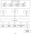
- FIG. 4 is a schematic structural diagram of a computer system suitable for implementing an electronic device according to an embodiment of this application. It should be noted that the computer system of the electronic device shown in FIG. 4 is merely an example, and should not impose any limitation on a function and a use range of the embodiments of this application.
- the computer system includes a central processing unit (Central Processing Unit, CPU).
- the CPU may perform various proper actions and processing based on a program stored in a read-only memory (Read-Only Memory, ROM) or a program loaded from a storage portion to a random access memory (Random Access Memory, RAM), for example, perform the method provided in the foregoing embodiments.
- the RAM further stores various programs and data required for a system operation.
- the CPU, the ROM, and the RAM are connected to each other through a bus.
- An input/output (Input/Output, I/O) interface is also connected to the bus.
- the following parts are connected to the I/O interface: an input portion including a keyboard, a mouse, and the like; an output portion including a cathode ray tube (Cathode Ray Tube, CRT), a liquid crystal display (Liquid Crystal Display, LCD), a speaker, and the like; the storage portion including a hard disk, and the like; and a communication portion including a network interface card such as a LAN (Local Area Network, local area network) card or a modem.
- the communication portion performs communication processing via a network such as the Internet.
- a driver is also connected to the I/O interface according to a requirement.
- a removable medium such as a magnetic disk, an optical disc, a magneto-optical disc, or a semiconductor memory is mounted on the driver according to a requirement, so that a computer program read from the removable medium is installed into the storage portion based on a requirement.
- a process described above with reference to the flowchart may be implemented as a computer software program.
- a computer program product is included.
- the computer program product includes a computer program carried on a computer-readable medium, and the computer program includes a computer program used to perform the vehicle control method shown in FIG. 2 .
- the computer program may be downloaded and installed from a network through the communication portion, and/or installed from the removable medium.
- CPU central processing unit
- the computer-readable medium described in the embodiments of this application may be a computer-readable signal medium, a computer-readable storage medium, or any combination thereof.
- the computer-readable storage medium may be, for example, an electrical system, apparatus, or device, a magnetic system, apparatus, or device, an optical system, apparatus, or device, an electromagnetic system, apparatus, or device, an infrared system, apparatus, or device, or a semiconductor system, apparatus, or device, or any combination thereof.
- a more specific example of the computer-readable storage medium may include but is not limited to an electrical connection having one or more wires, a portable computer disk, a hard disk, a random access memory (RAM), a read-only memory (ROM), an erasable programmable read-only memory (Erasable Programmable Read Only Memory, EPROM), a flash memory, an optical fiber, a portable compact disk read-only memory (Compact Disc Read-Only Memory, CD-ROM), an optical storage device, a magnetic storage device, or any proper combination thereof.
- the computer-readable signal medium may include a data signal propagated in a baseband or as a part of a carrier, and carries a computer-readable computer program.
- the propagated data signal may be in a plurality of forms, including but not limited to an electromagnetic signal, an optical signal, or any suitable combination thereof.
- the computer-readable signal medium may alternatively be any computer-readable medium other than a computer-readable storage medium, and the computer-readable medium may send, propagate, or transmit a program used by or in combination with an instruction execution system, apparatus, or device.
- the computer program included in the computer-readable medium may be transmitted by using any proper medium, including but not limited to a wireless medium or a wired medium, or any proper combination thereof.
- each block in the flowcharts or block diagrams may represent a module, a program segment, or a part of code, and the module, the program segment, or the part of code includes one or more executable instructions for implementing a specified logical function.
- a function marked in the block may also occur in a sequence different from that marked in the accompanying drawings. For example, two consecutively represented blocks may be actually executed substantially in parallel, and may sometimes be executed in a reverse order, depending on a function involved.
- each block in the block diagrams or the flowcharts and a combination of blocks in the block diagrams or the flowcharts may be implemented by using a dedicated hardware-based system designed to perform a specified function or operation, or may be implemented by using a combination of dedicated hardware and computer instructions.
- the units involved in the embodiments of this application may be implemented by using software, or may be implemented by using hardware, and the units described may also be disposed in a processor. Names of these units do not constitute a limitation on the units in a specified case.
- the computer-readable storage medium stores a computer program, and when the computer program is executed by a processor of a computer, the computer is enabled to perform the foregoing vehicle control method.
- the computer-readable storage medium may be included in the electronic device described in the foregoing embodiments, or may exist separately, and is not assembled into the electronic device.
- the computer program product or the computer program includes computer instructions, and the computer instructions are stored in a computer-readable storage medium.
- a processor of a computer device reads the computer instructions from the computer-readable storage medium, and the processor executes the computer instructions, to enable the computer device to perform the vehicle control method provided in the foregoing embodiments.
- An embodiment of this application further provides a vehicle according to the present invention.
- the vehicle is controlled by using the vehicle control method shown in FIG. 2 .
Landscapes
- Engineering & Computer Science (AREA)
- Power Engineering (AREA)
- Transportation (AREA)
- Mechanical Engineering (AREA)
- Life Sciences & Earth Sciences (AREA)
- Sustainable Development (AREA)
- Sustainable Energy (AREA)
- Electric Propulsion And Braking For Vehicles (AREA)
- Control Of Transmission Device (AREA)
- Vehicle Body Suspensions (AREA)
Abstract
Description
- The present invention relates to the field of motor vibration control, and in particular, to a vehicle control method and apparatus, and device, medium, vehicle and product.
- Active torsional vibration control of a battery electric vehicle is very important. Under the action of electromechanical coupling, a system has a relatively large quantity of interference torques, causing abnormal impact. This seriously affects reliability and vibration noise characteristics of a component of a powertrain system, directly affects riding experience of a passenger, also directly affects dynamics and an energy recovery capability, and further profoundly affects brand publicity. An improper vibration level even affects fatigue and durability performance of an important component, which affects driving safety of a person.
- Currently, there are some problems in a common technical solution. When an accelerator pedal is pressed down, a technical measure to reduce a torque gradient is taken to avoid affecting driving smoothness. This affects dynamics of an entire vehicle. In addition, when the accelerator pedal is released, a technical measure to reduce energy recovery intensity is taken to avoid affecting driving smoothness. This affects economy of the entire vehicle. An underlying reason lies in that a dynamics model of the powertrain system is relatively complex, and there are errors caused by various clearances such as a tooth-side radial clearance, a tooth-side axial clearance, a spline clearance, a semi-axis ball cage contact clearance, and a bearing clearance. In addition, the component has flexibility, and may be circumferentially deformed. It is very difficult to describe these impact factors by using a very accurate mathematical model. In the entire system, torsional vibration accompanies a sudden change in a torque, causing a serious driving smoothness problem. Based on a current distributed control system architecture design, an entire vehicle control unit cannot calculate an execution torque for avoiding torsional vibration. Therefore, the entire vehicle control unit calculates only an initial value of the execution torque, which is modified and improved by a motor controller.
- Currently, active torsional vibration control technical solutions commonly used in China or abroad include feedforward control and feedback control. Feedforward control mainly compensates for the torque directly by limiting an abnormal speed change in the system. Feedforward control is essentially speed closed-loop feedback control. This technical solution has relatively slight impact on dynamics. Because a low-pass filter is used, energy recovery intensity is relatively greatly affected, which is usually not conducive to energy recovery. There are also many feedback control solutions, which may be classified into two types based on different control objectives. One type is a control solution in which a fluctuation magnitude in a rotational speed of a motor is reduced, which is equivalent to reducing a time derivative of a relative angular displacement error. The other type is reducing a relative angular displacement error. Active control may be classified into two types based on different signal types to be used. A first type uses only a motor speed signal. A second type further uses a wheel speed signal in addition to using the motor speed signal. Active control may alternatively be classified into three types based on different control types. One type is a proportional-integral-derivative controller (PID), another type is using an optimal controller (LQR), and the last type is using a sliding mode controller (SMC). For example, both
CN101550986A andCN112746875A can implement torsional vibration control. However, a current control solution is imperfect, and some dynamic performance and economic performance of the vehicle are compromised. If a plurality of controllers are switched at an algorithm level, it is likely that there is no solution to a problem or the torque abnormally changes suddenly. These control solutions all affect robustness of an entire control system. - In view of the foregoing disadvantages of the conventional technology, the present invention provides a vehicle control method and apparatus, a device, a medium, a vehicle, and a product, to resolve the foregoing technical problems.
- The present invention provides a vehicle control method. The method includes:
- obtaining a current working state of a vehicle;
- calculating a transmission error of the vehicle in the current working state;
- determining, based on the transmission error and a preset powertrain system equivalent clearance, whether the vehicle meets a state switching condition; and
- switching the current working state of the vehicle when the vehicle meets the state switching condition.
- In an embodiment of the present invention, the current working state of the vehicle is a clearance state or a contact state, and the state switching condition includes a first state switching condition and a second state switching condition;
- a first transmission error of the vehicle in the clearance state is calculated when the current working state of the vehicle is the clearance state;
- when the first transmission error is greater than the preset powertrain system equivalent clearance, the vehicle meets the first state switching condition, the current working state of the vehicle is switched from the clearance state to the contact state, the vehicle is controlled by using a first torque, and the first torque is a sum of a requested torque sent by an entire vehicle control unit to a motor control unit and a first superposed torque in the contact state;
- a second transmission error of the vehicle in the contact state is calculated when the current working state of the vehicle is the contact state; and
- when the second transmission error is less than or equal to the preset powertrain system equivalent clearance, the vehicle meets the second state switching condition, the current working state of the vehicle is switched from the contact state to the clearance state, the vehicle is controlled by using a second torque, and the second torque is a sum of the requested torque sent by the entire vehicle control unit to the motor control unit and a second superposed torque in the clearance state.
- In an embodiment of the present invention, the transmission error is represented as follows:

- Herein, Δθ 1 is the first transmission error, Δθ 2 denotes the second transmission error, cs denotes a half-axis equivalent viscous damping coefficient, Ths is a half-axis torque, ks is half-axis equivalent stiffness, and α is the powertrain system equivalent clearance.
- In an embodiment of the present invention, the first torque is represented as Tm □ TqReq + δTq 1 , and the second torque is represented as Tm □ TqReq + δTq 2 .
- Herein, TqReq is the requested torque sent by the entire vehicle control unit to the motor control unit, δTq 1 is the first superposed torque, and δTq 2 is the second superposed torque.

- Herein, λ is a speed ratio, δ is a constant, Δθ̇ is a time derivative of Δθ 1, gm □ TqReq - cmθ̇m - Jmθ̈m , ġm is a derivative of gm, cm is a motor end equivalent viscous damping, θ̇m is an angular velocity of a motor rotor, Jm is a moment of inertia of the motor rotor, θ̈m is real-time angular acceleration of the motor rotor, and Δ is a control parameter.
- In an embodiment of the present invention, the superposed torque is as follows:


- Herein, η is an angular acceleration uncertainty amplitude.
- In an embodiment of the present invention, when the vehicle is in the clearance state, the superposed torque is as follows:

- Herein, δTq k+1 denotes a new second superposed torque, |η| <ηB , and ηB is a minimum value of an upper limit of the angular acceleration uncertainty amplitude.
- In an embodiment of the present invention, the control parameter Δ is represented as follows:

- In an embodiment of the present invention, the method further includes: limiting an amplitude of the requested torque when the requested torque is greater than a torque threshold.
- The present invention provides a vehicle control apparatus. The apparatus includes:
- a state obtaining module, configured to obtain a current working state of a vehicle;
- an error calculation module, configured to calculate a transmission error of the vehicle in the current working state;
- a condition determining module, configured to determine, based on the transmission error and a preset powertrain system equivalent clearance, whether the vehicle meets a state switching condition; and
- a state switching module, configured to switch the current working state of the vehicle when the vehicle meets the state switching condition.
- The present invention provides an electronic device. The electronic device includes:
- one or more processors; and
- a storage apparatus, configured to store one or more programs, where when the one or more programs are executed by the one or more processors, the electronic device is enabled to implement steps of the foregoing vehicle control method.
- The present invention provides a computer-readable storage medium. The computer-readable storage medium stores a computer program, and when the computer program is executed by a processor of a computer, the computer is enabled to perform steps of the foregoing vehicle control method.
- The present invention provides a vehicle. The vehicle is controlled by using the foregoing vehicle control method.
- The present invention provides a computer program product, including a computer program carried on a computer-readable medium. The computer program includes a computer program used to perform the foregoing vehicle control method.
- The present invention provides a vehicle control method and apparatus, a device, and a medium. The method includes: obtaining a current working state of a vehicle; calculating a transmission error of the vehicle in the current working state; determining, based on the transmission error and a preset powertrain system equivalent clearance, whether the vehicle meets a state switching condition; and switching the current working state of the vehicle when the vehicle meets the state switching condition. According to the present invention, impact between components of the vehicle can be reduced, component durability can be improved, and energy recovery intensity can be strengthened without compromising driving smoothness.
- It should be understood that the foregoing general descriptions and the following detailed descriptions are merely examples and explanations, and cannot limit this application.
- The accompanying drawings herein are incorporated in this specification, constitute a part of this specification, show embodiments in accordance with this application, and are used with this specification to explain a principle of this application. Clearly, the accompanying drawings in the following descriptions are merely some embodiments of this application. A person of ordinary skill in the art may still derive other drawings from these accompanying drawings without creative efforts. In the accompanying drawings:
-
FIG. 1 is a schematic diagram of an implementation environment of a vehicle control method according to an example embodiment of this application; -
FIG. 2 is a flowchart of a vehicle control method according to an example embodiment of this application; -
FIG. 3 is a block diagram of a vehicle control apparatus according to an example embodiment of this application; and -
FIG. 4 is a schematic structural diagram of a computer system of an electronic device suitable for implementing an embodiment of this application. - The following describes implementations of the present invention with reference to accompanying drawings and preferred embodiments. A person skilled in the art can easily understand other advantages and effects of the present invention based on content disclosed in this specification. The present invention may be further implemented or applied by using other different specific implementations. Various details in this specification may also be modified or altered based on different viewpoints and applications without departing from the present invention. It should be understood that the preferred embodiments are merely intended to describe the present invention, and are not intended to limit the protection scope of the present invention.
- It should be noted that the figures provided in the following embodiments merely schematically describe the basic concept of the present invention. Therefore, the figures display only components related to the present invention instead of being drawn based on a quantity, shapes, and sizes of components in actual implementation. Forms, the quantity, and a ratio of the components in actual implementation of the figures may be randomly changed, and a component layout form of the figures may also be more complex.
- In the following descriptions, a large quantity of details are discussed to provide a more thorough explanation of the embodiments of the present invention. However, it is clear to a person skilled in the art that the embodiments of the present invention may be implemented without these specific details. In other embodiments, well-known structures and devices are shown in a block diagram rather than in a detail form, to avoid making the embodiments of the present invention difficult to understand.
-
FIG. 1 is a schematic diagram of an example implementation environment of a vehicle control method according to this application. In this implementation environment, an entirevehicle control unit 110 and a motor control unit are included, and the entirevehicle control unit 110 and themotor control unit 120 exchange data through a CAN bus. In this implementation environment, the entire vehicle control unit may obtain a current working state of a vehicle; calculate a transmission error of the vehicle in the current working state; determine, based on the transmission error and a preset powertrain system equivalent clearance, whether the vehicle meets a state switching condition; and switch the current working state of the vehicle when the vehicle meets the state switching condition, to implement control of the vehicle. According to the present invention, impact between components of the vehicle can be reduced, component durability can be improved, and a larger torque rising gradient and a larger torque falling gradient can be allowed without compromising driving smoothness, to achieve stronger dynamics and stronger economy. - Embodiments of this application respectively provide a vehicle control method, a vehicle control apparatus, an electronic device, and a computer-readable storage medium. The following describes these embodiments in detail.
- Before the vehicle control method and the vehicle control apparatus in the embodiments are described in detail, an active control policy is first described. A clear time variable mark is omitted, and a derivative also indicates to perform derivation on a time variable. A specific variable is used as an example.

- The active control policy is based on the following dynamics model.
- It is considered to build a powertrain system torsional vibration mechanical model with a clearance(gap). If a moment of inertia of a motor rotor is Jm, an actual motor electromagnetic torque is Tm, a motor end equivalent viscous damping is cm, a speed ratio is λ, and a powertrain system equivalent clearance included angle is α, a motor end equivalent dynamics model is as follows:


- Herein, Jm is the moment of inertia of the rotor, θ̇m is an angular velocity of the motor rotor, θ̈m is angular acceleration of the motor rotor, Ths is a half-axis torque, ks is half-axis equivalent stiffness, cs is a half-axis equivalent viscous damping coefficient, sgn( ) is a symbol function, Δθ is a transmission error, and Δθ represents a difference between a motor end angular displacement and a wheel end angular displacement in a case of flexible transmission, Δθ̇ is a transmission error rate and is a time derivative of Δθ, |Δθ| >α, which represents that a vehicle in a contact state, that is, is switched from a clearance state to the contact state, and |Δθ| ≤α, which represents that the vehicle is in the clearance state, that is, is switched from the contact state to the clearance state.
- The following transmission error (TE) is defined.

- Herein, θ̇m is a motor angular displacement, and θw is the wheel end angular displacement, and is a relative angular displacement. The transmission error represents an error caused by the flexible transmission. An ideal value of the transmission error is zero on an assumption of rigid transmission. Actually, the transmission error is not zero, indicating that the powertrain system is flexible. An objective of active control is selected to control the following error quantity, to minimize a value of such error quantity:

- Then, actual motor electromagnetic torque of vehicle active control is defined as follows:

- Herein, TqReq is a requested torque sent by an entire vehicle control unit to a motor control unit, is a motor torque obtained after the entire vehicle control unit considers a real-time requirement of each subsystem, is converted from an accelerator pedal signal in most cases, and represents a direct current component of the actual motor electromagnetic torque; and δTq is a superposed torque, is a torque that needs to be superposed when driving smoothness is further considered, and represents an alternating current component of the actual motor electromagnetic torque.
- The following new variable is introduced:

- In this way, an expression of a half-axis load or the half-axis torque may be obtained:

- Through time derivation, half-axis torque rates in two states can be learned of:

- To monitor a half-axis state, the transmission error Δθ needs to be calculated by performing real-time integration on the transmission error rate. Different integration formulas are selected based on different states:

- It is assumed that an exact parameter is obtained through calibration and a test. The following deduces the detailed active control policy.
- The active control policy includes a control policy in the clearance state and a control policy in the contact state.
- In the clearance state, it is marked that |Δθ|≤α is met in this case, and the control policy is deduced as follows:


- Herein, Δθ̇ is a first derivative of Δθ, Δθ̈ is a second derivative of Δθ, Δ is a control parameter.
- It is assumed that the half-axis equivalent viscous damping coefficient is greater than zero.
- In the contact state, it is marked that |Δθ| > α is met in this case, and a control policy is deduced as follows:

- In combination of the foregoing two cases, it can be learned that the superposed torque is as follows:

- To resolve a robust control problem caused by parameter uncertainty, stability and convergence of an algorithm under impact of the uncertainty need to be analyzed, and a control algorithm needs to be optimized. The uncertainty can be attributed to an error η (an angular acceleration uncertainty amplitude) of the angular acceleration. That is, the original equations (1) and (2) are modified to (14).

- In an actual case, there is the following uncertainty limit:

- Herein, ηB is a minimum value of an upper limit of the angular acceleration uncertainty amplitude.
- When a parameter is proper, a lower limit of the uncertainty is very small, or a debugging purpose is to minimize a value in the foregoing formula. Angular acceleration uncertainty is amplified by the moment of inertia, is converted into half-axis torque uncertainty, and is retained in gm, and the half-axis torque uncertainty is further transmitted to the relative angular displacement g̃m and a relative angular velocity


- If the angular acceleration uncertainty is invariant, or is invariant in a short time, a derivative term of gm is not affected. However, gm is actually a biased estimator, and represents that a denominator in an integration includes an uncertainty term in a case of a clearance. Therefore, formula (13) may be changed to obtain formula (17).

- The uncertainty term essentially affects precise determining of a clearance moment, to further affect whether a control law integration policy is normally switched. To resolve this problem, a control law and parameter adaptation of the clearance moment need to be carefully designed. It can be learned through further deduction that an uncertainty parameter may be selected as follows:

- Formula (18) provides a recommendation to a value of the control parameter Δ. Such selection helps ensure robustness.
-
FIG. 2 is a flowchart of a vehicle control method according to an example embodiment of this application. The method may be applied to the implementation environment shown inFIG. 1 , and is specifically performed by the entire vehicle control unit in the implementation environment. It should be understood that the method may also be applied to another example implementation environment, and is specifically performed by a device in the another implementation environment. This embodiment sets no limitation on an implementation environment to which the method is applicable. -
FIG. 2 is a flowchart of a vehicle control method according to an example of this application. The vehicle control method includes at least step S210 to step S240. Details are described as follows: - Step S210: Obtain a current working state of a vehicle.
- Step S220: Calculate a transmission error of the vehicle in the current working state.
- Step S230: Determine, based on the transmission error and a preset powertrain system equivalent clearance, whether the vehicle meets a state switching condition.
- Step S240: Switch the current working state of the vehicle when the vehicle meets the state switching condition.
- According to the present invention, impact between components of the vehicle can be reduced, component durability can be improved, and energy recovery intensity can be strengthened without compromising driving smoothness.
- The following describes the steps in the vehicle control method in detail.
- In step S210, the current working state of the vehicle is obtained.
- In this embodiment, working states of the vehicle includes a contact state and a clearance state, and the current working state is the contact state or the clearance state. When the solution of the present invention is analyzed, an initial state is usually set to the clearance state.
- In step S220, the transmission error of the vehicle in the current working state is calculated.
- The transmission error represents a difference between a motor end angular displacement and a wheel end angular displacement in a case of flexible transmission. The transmission error is an indicator for evaluating the working state of the vehicle, and is a value that changes in real time. When the transmission error is greater than a powertrain system equivalent clearance, it is defined as a working state of the vehicle, namely, the contact state; and when the transmission error is less than or equal to the powertrain system equivalent clearance, it is defined as another working state of the vehicle, namely, the clearance state. At an initial moment of program running, it is considered by default that the vehicle is in the clearance state, and an initial value of the transmission error is zero. The transmission error determines how to switch between different states. In different states, different calculation formulas are selected to calculate the transmission error.
- In this embodiment, the transmission error is represented by Δθ, and a calculation manner of the transmission error Δθ is performing integration on a transmission error rate.

- Because the working states of the vehicle include the two working states, namely, the contact state and the clearance state, there are two calculation manners of the transmission error.
- In an embodiment, the transmission error is represented as follows:

- Herein, Δθ 1 is a first transmission error, Δθ 2 denotes a second transmission error, cs denotes a half-axis equivalent viscous damping coefficient, Ths is a half-axis torque, ks is half-axis equivalent stiffness, and α is the powertrain system equivalent clearance.
- To be specific, when the vehicle is in the contact state, the first transmission error is calculated based on a calculation formula of Δθ 1; and when the vehicle is in the clearance state, the second transmission error is calculated based on a calculation formula of Δθ 1.
- In step S230, whether the vehicle meets the state switching condition is determined based on the transmission error and the preset powertrain system equivalent clearance.
- To be specific, the calculated transmission error and the preset powertrain system equivalent clearance are compared, and whether the state switching condition is met is determined based on a comparison result. That is, whether the state switching condition is met is determined based on a value of |Δθ| and a value of α .
- In step S240, the current working state of the vehicle is switched when the vehicle meets the state switching condition.
- When |Δθ| > α, it indicates that the vehicle meets the state switching condition, and the working state of the vehicle is switched from the clearance state to the contact state.
- When |Δθ| ≤α, it indicates that the vehicle meets the state switching condition, and the working state of the vehicle is switched from the contact state to the clearance state.
- In an embodiment, the current working state of the vehicle is a clearance state or a contact state, and the state switching condition includes a first state switching condition and a second state switching condition;
- a first transmission error of the vehicle in the clearance state is calculated when the current working state of the vehicle is the clearance state;
- when the first transmission error is greater than the preset powertrain system equivalent clearance, the vehicle meets the first state switching condition, the current working state of the vehicle is switched from the clearance state to the contact state, the vehicle is controlled by using a first torque, and the first torque is a sum of a requested torque sent by an entire vehicle control unit to a motor control unit and a first superposed torque in the contact state;
- a second transmission error of the vehicle in the contact state is calculated when the current working state of the vehicle is the contact state; and
- when the second transmission error is less than or equal to the preset powertrain system equivalent clearance, the vehicle meets the second state switching condition, the current working state of the vehicle is switched from the contact state to the clearance state, the vehicle is controlled by using a second torque, and the second torque is a sum of the requested torque sent by the entire vehicle control unit to the motor control unit and a second superposed torque in the clearance state.
- In an embodiment, the first torque is represented as Tm □ TqReq + δTq 1 , and the second torque is represented as Tm □ TqReq + δTq 2 .
- TqReq is the requested torque sent by the entire vehicle control unit to the motor control unit, and is a motor torque obtained after the entire vehicle control unit considers a real-time requirement of each subsystem. δTq 1 is the first superposed torque of the vehicle in the contact state, and is an additional torque calculated by an electric drive control unit based on an active torsional vibration control requirement. δTq 2 is the second superposed torque of the vehicle in the clearance state, and is an additional torque calculated by the electric drive control unit based on the active torsional vibration control requirement.

- Herein, λ is a speed ratio, δ is a constant, Δθ̇ is a time derivative of Δθ 1, gm □ TqReq - cmθ̇m -Jmθ̈m , ġm is a derivative of gm, cm is a motor end equivalent viscous damping, θ̇m is an angular velocity of a motor rotor, Jm is a moment of inertia of the motor rotor, θ̈m is real-time angular acceleration of the motor rotor, and Δ is a control parameter.
- When the control parameter is proper, a lower limit of uncertainty is very small, or a debugging purpose is to minimize a value in the foregoing formula. Angular acceleration uncertainty is amplified by the moment of inertia, is converted into half-axis torque uncertainty, and is retained in gm, and the half-axis torque uncertainty is further transmitted to a relative angular displacement g̃m and a relative angular velocity

- If the angular acceleration uncertainty is invariant, or is invariant in a short time, a derivative term of gm is not affected. However, gm is actually a biased estimator, and represents that a denominator in an integration includes an uncertainty term in a case of a clearance. Therefore, the superposed torque


- Herein, η is an angular acceleration uncertainty amplitude.
- It can be learned through further deduction that an uncertainty parameter (the control parameter) may be selected as follows:

- The foregoing formula provides a solution to a value of the control parameter Δ. Such selection helps ensure robustness.
- As described above, a powertrain system of the vehicle has two working states, including the clearance state and the contact state. If the working state is the clearance state, an integration formula of the superposed torque δTq is

- For integral prediction,

- For integral correction,

- It should be understood that sequence numbers of steps in the foregoing embodiments do not mean execution sequences. Execution sequences of the processes should be determined according to functions and internal logic of the processes, and should not be construed as any limitation on the implementation processes of the embodiments of the present invention.
- It should be noted that if the requested torque calculated by the entire vehicle control unit is incorrect or a calculated electromagnetic torque Tm exceeds a specific amplitude, the amplitude needs to be limited, and the amplitude is controlled to fall within a specific range, to prevent the superposed torque from overflowing or being abnormal. An amplitude limitation output result is used as an integral initial value of a next time step.
- If the motor runs in a mode other than the clearance state and the contact state, a power output is stopped or reduced, to avoid outputting an abnormal torque, and ensure normal running. For a motor working mode, the working mode is determined after the entire vehicle control unit combines requirements of all subsystems.
-
FIG. 3 is a block diagram of a vehicle control apparatus according to an example embodiment of this application. The apparatus may be applied to the implementation environment shown inFIG. 1 , and is specifically configured in an entire vehicle control unit. The apparatus may also be applied to another example implementation environment, and is specifically configured in another device. This embodiment sets no limitation on an implementation environment to which the apparatus is applicable. - As shown in
FIG. 3 , this application provides a vehicle control apparatus. The apparatus includes: - a
state obtaining module 310, configured to obtain a current working state of a vehicle; - an
error calculation module 320, configured to calculate a transmission error of the vehicle in the current working state; - a
condition determining module 330, configured to determine, based on the transmission error and a preset powertrain system equivalent clearance, whether the vehicle meets a state switching condition; and - a
state switching module 340, configured to switch the current working state of the vehicle when the vehicle meets the state switching condition. - It should be noted that the vehicle control apparatus provided in the foregoing embodiment and the vehicle control method provided in the foregoing embodiments belong to a same concept. A specific manner in which each module and unit perform an operation is described in detail in the method embodiment. Details are not described herein again. In actual applications, the vehicle control apparatus provided in the foregoing embodiment may allocate the foregoing functions to different functional modules according to a requirement, that is, divide an internal structure of the apparatus into different functional modules, to complete all or some functions described above. This is not limited herein.
- An embodiment of this application further provides an electronic device, including: one or more processors; and a storage apparatus, configured to store one or more programs. When the one or more programs are executed by one or more processors, the electronic device is enabled to implement the vehicle control method provided in the foregoing embodiments.
-
FIG. 4 is a schematic structural diagram of a computer system suitable for implementing an electronic device according to an embodiment of this application. It should be noted that the computer system of the electronic device shown inFIG. 4 is merely an example, and should not impose any limitation on a function and a use range of the embodiments of this application. - As shown in
FIG. 4 , the computer system includes a central processing unit (Central Processing Unit, CPU). The CPU may perform various proper actions and processing based on a program stored in a read-only memory (Read-Only Memory, ROM) or a program loaded from a storage portion to a random access memory (Random Access Memory, RAM), for example, perform the method provided in the foregoing embodiments. The RAM further stores various programs and data required for a system operation. The CPU, the ROM, and the RAM are connected to each other through a bus. An input/output (Input/Output, I/O) interface is also connected to the bus. - The following parts are connected to the I/O interface: an input portion including a keyboard, a mouse, and the like; an output portion including a cathode ray tube (Cathode Ray Tube, CRT), a liquid crystal display (Liquid Crystal Display, LCD), a speaker, and the like; the storage portion including a hard disk, and the like; and a communication portion including a network interface card such as a LAN (Local Area Network, local area network) card or a modem. The communication portion performs communication processing via a network such as the Internet. A driver is also connected to the I/O interface according to a requirement. A removable medium such as a magnetic disk, an optical disc, a magneto-optical disc, or a semiconductor memory is mounted on the driver according to a requirement, so that a computer program read from the removable medium is installed into the storage portion based on a requirement.
- In particular, according to the embodiments of this application, a process described above with reference to the flowchart may be implemented as a computer software program. For example, in an embodiment of this application, a computer program product is included. The computer program product includes a computer program carried on a computer-readable medium, and the computer program includes a computer program used to perform the vehicle control method shown in
FIG. 2 . In such an embodiment, the computer program may be downloaded and installed from a network through the communication portion, and/or installed from the removable medium. When the computer program is executed by the central processing unit (CPU), various functions defined in the system of this application are executed. - It should be noted that the computer-readable medium described in the embodiments of this application may be a computer-readable signal medium, a computer-readable storage medium, or any combination thereof. The computer-readable storage medium may be, for example, an electrical system, apparatus, or device, a magnetic system, apparatus, or device, an optical system, apparatus, or device, an electromagnetic system, apparatus, or device, an infrared system, apparatus, or device, or a semiconductor system, apparatus, or device, or any combination thereof. A more specific example of the computer-readable storage medium may include but is not limited to an electrical connection having one or more wires, a portable computer disk, a hard disk, a random access memory (RAM), a read-only memory (ROM), an erasable programmable read-only memory (Erasable Programmable Read Only Memory, EPROM), a flash memory, an optical fiber, a portable compact disk read-only memory (Compact Disc Read-Only Memory, CD-ROM), an optical storage device, a magnetic storage device, or any proper combination thereof. In this application, the computer-readable signal medium may include a data signal propagated in a baseband or as a part of a carrier, and carries a computer-readable computer program. The propagated data signal may be in a plurality of forms, including but not limited to an electromagnetic signal, an optical signal, or any suitable combination thereof. The computer-readable signal medium may alternatively be any computer-readable medium other than a computer-readable storage medium, and the computer-readable medium may send, propagate, or transmit a program used by or in combination with an instruction execution system, apparatus, or device. The computer program included in the computer-readable medium may be transmitted by using any proper medium, including but not limited to a wireless medium or a wired medium, or any proper combination thereof.
- The flowcharts and block diagrams in the accompanying drawings show system architectures, functions, and operations that may be implemented by systems, methods, and computer program products according to various embodiments of this application. Each block in the flowcharts or block diagrams may represent a module, a program segment, or a part of code, and the module, the program segment, or the part of code includes one or more executable instructions for implementing a specified logical function. It should also be noted that, in some alternative implementations, a function marked in the block may also occur in a sequence different from that marked in the accompanying drawings. For example, two consecutively represented blocks may be actually executed substantially in parallel, and may sometimes be executed in a reverse order, depending on a function involved. It should also be noted that each block in the block diagrams or the flowcharts and a combination of blocks in the block diagrams or the flowcharts may be implemented by using a dedicated hardware-based system designed to perform a specified function or operation, or may be implemented by using a combination of dedicated hardware and computer instructions.
- The units involved in the embodiments of this application may be implemented by using software, or may be implemented by using hardware, and the units described may also be disposed in a processor. Names of these units do not constitute a limitation on the units in a specified case.
- Another aspect of this application further provides a computer-readable storage medium. The computer-readable storage medium stores a computer program, and when the computer program is executed by a processor of a computer, the computer is enabled to perform the foregoing vehicle control method. The computer-readable storage medium may be included in the electronic device described in the foregoing embodiments, or may exist separately, and is not assembled into the electronic device.
- Another aspect of this application further provides a computer program product or a computer program. The computer program product or the computer program includes computer instructions, and the computer instructions are stored in a computer-readable storage medium. A processor of a computer device reads the computer instructions from the computer-readable storage medium, and the processor executes the computer instructions, to enable the computer device to perform the vehicle control method provided in the foregoing embodiments.
- An embodiment of this application further provides a vehicle according to the present invention. The vehicle is controlled by using the vehicle control method shown in
FIG. 2 . - The foregoing embodiments merely illustrate principles and effects of the present invention, but are not intended to limit the present invention. Any person skilled in the art may modify or alter the foregoing embodiments without departing from the scope of the present invention. Therefore, all equivalent modifications or alterations completed by a person of ordinary skill in the art without departing from the technical ideas disclosed in the present invention should still be covered by the claims of the present invention.
Claims (13)
- A vehicle control method, comprising:obtaining a current working state of a vehicle;calculating a transmission error of the vehicle in the current working state;determining, based on the transmission error and a preset powertrain system equivalent clearance, whether the vehicle meets a state switching condition; andswitching the current working state of the vehicle when the vehicle meets the state switching condition.
- The vehicle control method according to claim 1, wherein the current working state of the vehicle is a clearance state or a contact state, and the state switching condition comprises a first state switching condition and a second state switching condition;a first transmission error of the vehicle in the clearance state is calculated when the current working state of the vehicle is the clearance state;when the first transmission error is greater than the preset powertrain system equivalent clearance, determining that the vehicle meets the first state switching condition, the current working state of the vehicle is switched from the clearance state to the contact state, the vehicle is controlled by using a first torque, and the first torque is a sum of a requested torque sent by an entire vehicle control unit to a motor control unit and a first superposed torque in the contact state;a second transmission error of the vehicle in the contact state is calculated when the current working state of the vehicle is the contact state; andwhen the second transmission error is less than or equal to the preset powertrain system equivalent clearance, determining that the vehicle meets the second state switching condition, the current working state of the vehicle is switched from the contact state to the clearance state, the vehicle is controlled by using a second torque, and the second torque is a sum of the requested torque sent by the entire vehicle control unit to the motor control unit and a second superposed torque in the clearance state.
- The vehicle control method according to claim 2, wherein the transmission error is represented as follows:

Δθ 1 is the first transmission error, Δθ 2 denotes the second transmission error, cs denotes a half-axis equivalent viscous damping coefficient, Ths is a half-axis torque, ks is half-axis equivalent stiffness, and α is the powertrain system equivalent clearance. - The vehicle control method according to claim 3, wherein the first torque is represented as Tm □ TqReq + δTq 1 , and the second torque is represented as Tm □ TqReq + δTq 2 , whereinTqReq is the requested torque sent by the entire vehicle control unit to the motor control unit, δTq 1 is the first superposed torque, and δTq 2 is the second superposed torque; and
 λ is a speed ratio, δ is a constant, Δθ̇ is a time derivative of Δθ 1, gm □ TqReq-cmθ̇m -Jm θ̈ m , ġm is a derivative of gm, cm is a motor end equivalent viscous damping, θ̇m is an angular velocity of a motor rotor, Jm is a moment of inertia of the motor rotor, θ̈m is real-time angular acceleration of the motor rotor, and Δ is a control parameter.
 - The vehicle control method according to claim 4, wherein the superposed torque is as follows:
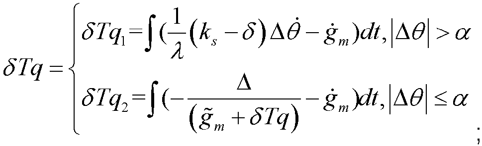

η is an angular acceleration uncertainty amplitude. - The vehicle control method according to claim 6, wherein when the vehicle is in the clearance state, the superposed torque is as follows:

δTq k+1 denotes a new second superposed torque, |η| <ηB , and ηB is a minimum value of an upper limit of the angular acceleration uncertainty amplitude. - The vehicle control method according to claim 5, wherein the control parameter Δ is represented as follows:

- The vehicle control method according to claim 2, 3, or 4, wherein the method further comprises:
limiting an amplitude of the requested torque when the requested torque is greater than a torque threshold. - A vehicle control apparatus, wherein the apparatus comprises:a state obtaining module, configured to obtain a current working state of a vehicle;an error calculation module, configured to calculate a transmission error of the vehicle in the current working state;a condition determining module, configured to determine, based on the transmission error and a preset powertrain system equivalent clearance, whether the vehicle meets a state switching condition; anda state switching module, configured to switch the current working state of the vehicle when the vehicle meets the state switching condition.
- An electronic device, wherein the electronic device comprises:one or more processors; anda storage apparatus, configured to store one or more programs, wherein when the one or more programs are executed by the one or more processors, the electronic device is enabled to implement steps of the vehicle control method according to any one of claims 1 to 8.
- A computer-readable storage medium, wherein the computer-readable storage medium stores a computer program, and when the computer program is executed by a processor of a computer, the computer is enabled to perform steps of the vehicle control method according to any one of claims 1 to 8.
- A vehicle, controlled by using the vehicle control method according to any one of claims 1 to 8.
- A computer program product, comprising a computer program carried on a computer-readable medium, wherein the computer program comprises a computer program used to perform the vehicle control method according to any one of claims 1 to 8.
Applications Claiming Priority (2)
| Application Number | Priority Date | Filing Date | Title |
|---|---|---|---|
| CN202211522370.2A CN115782617B (en) | 2022-11-30 | 2022-11-30 | Vehicle control method, device, equipment, medium, vehicle and product |
| PCT/CN2023/121335 WO2024114067A1 (en) | 2022-11-30 | 2023-09-26 | Vehicle control method and apparatus, and device, medium, vehicle and product |
Publications (2)
| Publication Number | Publication Date |
|---|---|
| EP4556296A1 true EP4556296A1 (en) | 2025-05-21 |
| EP4556296A4 EP4556296A4 (en) | 2025-12-10 |
Family
ID=85443925
Family Applications (1)
| Application Number | Title | Priority Date | Filing Date |
|---|---|---|---|
| EP23896224.5A Pending EP4556296A4 (en) | 2022-11-30 | 2023-09-26 | VEHICLE CONTROL METHOD AND DEVICE AS WELL AS DEVICE, MEDIUM, VEHICLE AND PRODUCT |
Country Status (3)
| Country | Link |
|---|---|
| EP (1) | EP4556296A4 (en) |
| CN (1) | CN115782617B (en) |
| WO (1) | WO2024114067A1 (en) |
Families Citing this family (2)
| Publication number | Priority date | Publication date | Assignee | Title |
|---|---|---|---|---|
| CN115782617B (en) * | 2022-11-30 | 2025-07-15 | 深蓝汽车科技有限公司 | Vehicle control method, device, equipment, medium, vehicle and product |
| CN120821186B (en) * | 2025-09-18 | 2025-12-02 | 上海易咖智车科技有限公司 | Vehicle speed closed-loop control method, system, vehicle and storage medium |
Family Cites Families (15)
| Publication number | Priority date | Publication date | Assignee | Title |
|---|---|---|---|---|
| CN101550986B (en) | 2009-05-02 | 2011-06-22 | 罗清 | Actively-controlled electronic torque vibration isolator and achieving method thereof |
| US8509979B2 (en) * | 2009-05-27 | 2013-08-13 | Toyota Jidosha Kabushiki Kaisha | Control apparatus for hybrid vehicle |
| JP5573456B2 (en) * | 2010-07-23 | 2014-08-20 | 日産自動車株式会社 | Vibration control device for electric vehicle and vibration control method for electric vehicle |
| DE102013104513A1 (en) * | 2012-05-04 | 2013-11-07 | Ford Global Technologies, Llc | Method for controlling powertrain backlash noise in vehicle system, involves reducing gear teeth impact through electric machine operation in speed control mode of drive train torque, during transition from negative to positive torque |
| CN104670213A (en) * | 2013-11-27 | 2015-06-03 | 上海汽车集团股份有限公司 | Torque control method for eliminating jitter caused in gaps of car transmission system |
| US9873422B2 (en) * | 2016-05-16 | 2018-01-23 | Ford Global Technologies, Llc | Driveline lash control method during driver tip-in/out |
| CN107472076B (en) * | 2016-06-24 | 2019-11-22 | 宝沃汽车(中国)有限公司 | Torque control method, device and the vehicle of vehicle |
| CN108052760B (en) * | 2017-12-25 | 2021-03-16 | 长安大学 | A Nonlinear Dynamic Calculation Method for Gear Pairs |
| CN110406389B (en) * | 2018-04-28 | 2021-04-06 | 广州汽车集团股份有限公司 | Control method, device, computer equipment and medium for vehicle driving comfort |
| CN112746875B (en) | 2019-10-31 | 2022-08-19 | 中国航发商用航空发动机有限责任公司 | Active control system and method for complex vibration of rotor shaft system of aircraft engine |
| CN113370573B (en) * | 2020-03-10 | 2023-01-20 | 山东省科学院激光研究所 | A system and method for suppressing clearance impact of a mechanical transmission system of a servo press |
| CN112960001A (en) * | 2021-04-19 | 2021-06-15 | 北京七鑫易维信息技术有限公司 | Driving mode switching method and device, vehicle and storage medium |
| CN113263923A (en) * | 2021-07-05 | 2021-08-17 | 珠海格力电器股份有限公司 | Motor control method and device of electric vehicle, storage medium and vehicle control unit |
| CN115071439B (en) * | 2022-06-14 | 2025-06-06 | 一汽解放汽车有限公司 | Vehicle body control method, device, computer equipment and storage medium |
| CN115782617B (en) * | 2022-11-30 | 2025-07-15 | 深蓝汽车科技有限公司 | Vehicle control method, device, equipment, medium, vehicle and product |
-
2022
- 2022-11-30 CN CN202211522370.2A patent/CN115782617B/en active Active
-
2023
- 2023-09-26 WO PCT/CN2023/121335 patent/WO2024114067A1/en not_active Ceased
- 2023-09-26 EP EP23896224.5A patent/EP4556296A4/en active Pending
Also Published As
| Publication number | Publication date |
|---|---|
| EP4556296A4 (en) | 2025-12-10 |
| CN115782617A (en) | 2023-03-14 |
| CN115782617B (en) | 2025-07-15 |
| WO2024114067A9 (en) | 2025-03-06 |
| WO2024114067A1 (en) | 2024-06-06 |
Similar Documents
| Publication | Publication Date | Title |
|---|---|---|
| EP4556296A1 (en) | Vehicle control method and apparatus, and device, medium, vehicle and product | |
| CN110126807B (en) | Vehicle speed control method, vehicle speed control system and vehicle | |
| CN113968146B (en) | A speed limit control method, device and system for an electric vehicle | |
| Wang et al. | Vibration control method for an electric city bus driven by a dual motor coaxial series drive system based on model predictive control | |
| CN114987555B (en) | Automatic driving longitudinal abnormal state determining method and device, electronic equipment and medium | |
| US20090235274A1 (en) | Apparatus and method for task count control | |
| US12508921B2 (en) | Control device for electric vehicle | |
| CN119058420B (en) | Vehicle torque control system, vehicle torque control method and vehicle | |
| CN119239315B (en) | Active gear engagement method, device, equipment and storage medium for new energy commercial vehicles | |
| EP4708113A1 (en) | Self-learning method and system for optimal economic curve of series power generation for hybrid vehicle model | |
| CN116678631B (en) | A method, apparatus, storage medium, and electronic device for optimizing vehicle drivability. | |
| CN115743136B (en) | Control method and device, equipment and computer readable storage medium | |
| CN115848378B (en) | Parameter updating method, vehicle control method, device, equipment and medium | |
| CN118478745A (en) | Electric balance correction method | |
| CN115972913B (en) | Torsional vibration control method, device, equipment and medium based on slip state | |
| CN115520175A (en) | Control method and device, equipment and computer readable storage medium | |
| CN113035403A (en) | Automatic control method for nuclear power plant under abnormal working condition | |
| US20240370343A1 (en) | System and method for real-time hardware in the loop | |
| CN116241648B (en) | A method for determining the shifting rules of an intelligent driving mine car and related equipment | |
| CN116252633B (en) | Differential quota method, device and equipment based on motor and storage medium | |
| CN115839408B (en) | Gear control method and device, electronic equipment and storage medium | |
| CN116238342B (en) | A method, apparatus, device, storage medium, and accelerator pedal mode switching method for electric vehicle transition torque output. | |
| CN115626157B (en) | Collision avoidance methods, devices, storage media and computer equipment | |
| CN120735609B (en) | A torque control method, device, and vehicle for a distributed drive vehicle. | |
| CN116107915B (en) | Quantification method and device for safety controllability index of vehicle expressway cruising function |
Legal Events
| Date | Code | Title | Description |
|---|---|---|---|
| STAA | Information on the status of an ep patent application or granted ep patent |
Free format text: STATUS: THE INTERNATIONAL PUBLICATION HAS BEEN MADE |
|
| PUAI | Public reference made under article 153(3) epc to a published international application that has entered the european phase |
Free format text: ORIGINAL CODE: 0009012 |
|
| STAA | Information on the status of an ep patent application or granted ep patent |
Free format text: STATUS: REQUEST FOR EXAMINATION WAS MADE |
|
| 17P | Request for examination filed |
Effective date: 20250217 |
|
| AK | Designated contracting states |
Kind code of ref document: A1 Designated state(s): AL AT BE BG CH CY CZ DE DK EE ES FI FR GB GR HR HU IE IS IT LI LT LU LV MC ME MK MT NL NO PL PT RO RS SE SI SK SM TR |
|
| A4 | Supplementary search report drawn up and despatched |
Effective date: 20251112 |
|
| RIC1 | Information provided on ipc code assigned before grant |
Ipc: B60L 15/20 20060101AFI20251106BHEP Ipc: B60L 7/18 20060101ALI20251106BHEP |
|
| DAV | Request for validation of the european patent (deleted) | ||
| DAX | Request for extension of the european patent (deleted) | ||
| GRAP | Despatch of communication of intention to grant a patent |
Free format text: ORIGINAL CODE: EPIDOSNIGR1 |
|
| STAA | Information on the status of an ep patent application or granted ep patent |
Free format text: STATUS: GRANT OF PATENT IS INTENDED |
|
| GRAS | Grant fee paid |
Free format text: ORIGINAL CODE: EPIDOSNIGR3 |
|
| GRAA | (expected) grant |
Free format text: ORIGINAL CODE: 0009210 |
|
| STAA | Information on the status of an ep patent application or granted ep patent |
Free format text: STATUS: THE PATENT HAS BEEN GRANTED |