EP4556251A1 - Printing device and printing cassette - Google Patents
Printing device and printing cassette Download PDFInfo
- Publication number
- EP4556251A1 EP4556251A1 EP24222864.1A EP24222864A EP4556251A1 EP 4556251 A1 EP4556251 A1 EP 4556251A1 EP 24222864 A EP24222864 A EP 24222864A EP 4556251 A1 EP4556251 A1 EP 4556251A1
- Authority
- EP
- European Patent Office
- Prior art keywords
- gear
- roll
- tape
- input
- output gear
- Prior art date
- Legal status (The legal status is an assumption and is not a legal conclusion. Google has not performed a legal analysis and makes no representation as to the accuracy of the status listed.)
- Pending
Links
Images




Classifications
-
- B—PERFORMING OPERATIONS; TRANSPORTING
- B41—PRINTING; LINING MACHINES; TYPEWRITERS; STAMPS
- B41J—TYPEWRITERS; SELECTIVE PRINTING MECHANISMS, i.e. MECHANISMS PRINTING OTHERWISE THAN FROM A FORME; CORRECTION OF TYPOGRAPHICAL ERRORS
- B41J15/00—Devices or arrangements of selective printing mechanisms, e.g. ink-jet printers or thermal printers, specially adapted for supporting or handling copy material in continuous form, e.g. webs
- B41J15/04—Supporting, feeding, or guiding devices; Mountings for web rolls or spindles
-
- B—PERFORMING OPERATIONS; TRANSPORTING
- B41—PRINTING; LINING MACHINES; TYPEWRITERS; STAMPS
- B41J—TYPEWRITERS; SELECTIVE PRINTING MECHANISMS, i.e. MECHANISMS PRINTING OTHERWISE THAN FROM A FORME; CORRECTION OF TYPOGRAPHICAL ERRORS
- B41J15/00—Devices or arrangements of selective printing mechanisms, e.g. ink-jet printers or thermal printers, specially adapted for supporting or handling copy material in continuous form, e.g. webs
- B41J15/04—Supporting, feeding, or guiding devices; Mountings for web rolls or spindles
- B41J15/044—Cassettes or cartridges containing continuous copy material, tape, for setting into printing devices
-
- B—PERFORMING OPERATIONS; TRANSPORTING
- B41—PRINTING; LINING MACHINES; TYPEWRITERS; STAMPS
- B41J—TYPEWRITERS; SELECTIVE PRINTING MECHANISMS, i.e. MECHANISMS PRINTING OTHERWISE THAN FROM A FORME; CORRECTION OF TYPOGRAPHICAL ERRORS
- B41J17/00—Mechanisms for manipulating page-width impression-transfer material, e.g. carbon paper
- B41J17/32—Detachable carriers or holders for impression-transfer material mechanism
-
- B—PERFORMING OPERATIONS; TRANSPORTING
- B41—PRINTING; LINING MACHINES; TYPEWRITERS; STAMPS
- B41J—TYPEWRITERS; SELECTIVE PRINTING MECHANISMS, i.e. MECHANISMS PRINTING OTHERWISE THAN FROM A FORME; CORRECTION OF TYPOGRAPHICAL ERRORS
- B41J3/00—Typewriters or selective printing or marking mechanisms characterised by the purpose for which they are constructed
- B41J3/36—Typewriters or selective printing or marking mechanisms characterised by the purpose for which they are constructed for portability, i.e. hand-held printers or laptop printers
-
- B—PERFORMING OPERATIONS; TRANSPORTING
- B65—CONVEYING; PACKING; STORING; HANDLING THIN OR FILAMENTARY MATERIAL
- B65H—HANDLING THIN OR FILAMENTARY MATERIAL, e.g. SHEETS, WEBS, CABLES
- B65H19/00—Changing the web roll
- B65H19/10—Changing the web roll in unwinding mechanisms or in connection with unwinding operations
- B65H19/12—Lifting, transporting, or inserting the web roll; Removing empty core
Definitions
- the present disclosure relates to a printing apparatus and a print cassette.
- the tape is replaced and supplied by attaching and detaching a cassette storing the tape to and from a main body.
- a cassette used in such an apparatus a cassette in which a gear is provided on a reel around which a tape is wound is known (refer to Patent Literature 1).
- Patent Literature 1 JP1983-141479A (published unexamined patent application)
- the gear is disposed in the vicinity of a surface of the case perpendicular to an axial direction of the reel. Therefore, when the cassette is dropped and the surface collides with something like a floor surface, the gear is susceptible to damage.
- An object of the present disclosure is to provide a printing apparatus and a print cassette capable of preventing damage to a gear that outputs a driving force to outside the cassette.
- An aspect of the present disclosure is a printing apparatus including a printing apparatus main body and a print cassette that is attachable to and detachable from the printing apparatus main body.
- the print cassette includes a roll of a first tape, a supply spool rotatable about a rotation axis, a second tape wound around the supply spool and used for printing or protecting of the first tape, an output gear to output a driving force outside, an input spool rotatable about a rotation axis, and an input gear directly or indirectly engaging the output gear to transmit the driving force to the output gear.
- a rotation axis of the input gear is located collinearly with the rotation axis of the input spool.
- the input spool, the input gear, and the roll are disposed in order of the input spool, the input gear, and the roll in the axial direction of the rotation axis of the supply spool.
- the supply spool, the output gear, and the roll are disposed in order of the supply spool, the output gear, and the roll in the axial direction of the rotation axis of the supply spool.
- the printing apparatus main body includes a print head to print on the first tape, a platen roller to convey the first tape, a platen gear coupled to the platen roller to engage the output gear, and a drive shaft to engage the input gear when inserted into the input spool to rotate the input spool and the input gear.
- the drive shaft engages the input gear and the platen gear engages the output gear, when the drive shaft rotates the input gear, the output gear is rotated, the platen gear rotates with rotation of the output gear, and the platen roller rotates with rotation of the platen gear.
- a print cassette including a roll of a first tape, a supply spool rotatable about a rotation axis, a second tape wound around the supply spool and used for printing or protecting of the first tape, and an output gear to output a driving force outside.
- the supply spool, the output gear, and the roll are disposed in order of the supply spool, the output gear, and the roll in the axial direction of the rotation axis of the supply spool.
- the print cassette attachable to and detachable from a printing apparatus main body.
- the print cassette includes a roll of a first tape, a supply spool rotatable about a rotation axis, a second tape wound around the supply spool and used for printing or protecting the first tape, an output gear to output a driving force outside, an input spool rotatable about a rotation axis, and an input gear directly or indirectly engaging the output gear to transmit the driving force to the output gear.
- a rotation axis of the input gear is located collinearly with the rotation axis of the input spool.
- the input spool, the input gear, and the roll are disposed in order of the input spool, the input gear, and the roll in the axial direction of the rotation axis of the supply spool.
- the supply spool, the output gear, and the roll are disposed in order of the supply spool, the output gear, and the roll in the axial direction of the rotation axis of the supply spool.
- the printing apparatus main body includes a print head to print on the first tape, a platen roller to convey the first tape, a platen gear coupled to the platen roller to engage the output gear, and a drive shaft to engage the input gear when inserted into the input spool to rotate the input spool and the input gear.
- a print cassette including a roll of a first tape, an output gear rotatable about a rotation axis to output a driving force outside, and a case in which at least a portion of the roll and at least a portion of the output gear are located and which has an exit from which the first tape pulled out from the roll is discharged.
- the exit, the output gear, and the roll are disposed in order of the exit, the output gear, and the roll in the axial direction of the rotation axis of the output gear.
- a printing apparatus 1 illustrated in FIGS. 1A, 1B, and 1C includes a print cassette 10 and a printing apparatus main body 100.
- the printing apparatus 1 is an apparatus that performs printing on a tape print medium.
- an axial direction of an output gear 18 is an up-down direction
- a direction perpendicular to the up-down direction in which the output gear 18 and an input spool 16 are aligned is a front-rear direction
- a direction perpendicular to both the up-down direction and the front-rear direction is a left-right direction
- the printing apparatus main body 100 includes a cassette insertion portion 101, a print head 102, a platen roller 103, a platen gear 104, and a drive shaft 105.
- the cassette insertion portion 101 is a recessed portion to which the print cassette 10 is attached.
- the cassette insertion portion 101 has a function of positioning the print cassette 10.
- the print head 102 is disposed in an interior of the cassette insertion portion 101.
- the print head 102 has a plurality of heating elements whose heat generation is to be individually controlled.
- a rotation axis L1 of the platen roller 103 is parallel to the up-down direction.
- the platen roller 103 is disposed near the print head 102 in the interior of the cassette insertion portion 101.
- the platen roller 103 is swingable in a direction toward or away from the print head 102.
- the platen gear 104 is coupled to the platen roller 103.
- a rotation axis L2 of the platen gear 104 is located collinearly with the rotation axis L1 of the platen roller 103.
- the platen gear 104 is swingable together with the platen roller 103.
- the drive shaft 105 is inserted into the input spool 16.
- the drive shaft 105 rotates the input spool 16.
- the drive shaft 105 is disposed in the interior of the cassette insertion portion 101.
- a rotation axis L3 of the drive shaft 105 is parallel to the up-down direction.
- the drive shaft 105 is rotated about the rotation axis L3 by a drive source (for example, a motor), which is not illustrated.
- the print cassette 10 houses a print medium.
- the print cassette 10 is attachable to and detachable from the printing apparatus main body 100. By replacing the print cassette 10, a print medium can be supplied and the type (for example, color, material, etc.) of print medium can be changed.
- the print cassette 10 includes a case 35 that houses a first tape 11A, an ink ribbon (an example of a second tape) 14A, and the like.
- the outer shape of the print cassette 10 i.e., the shape of the case 35
- the case 35 has a first lid portion 31, a first frame portion 32, a second frame portion 33, and a second lid portion 34.
- the print cassette 10 includes a first roll 11, a first supply spool 12, spacer films 13A and 13B, a second roll 14, a second supply spool 15, the input spool 16, a clutch spring holder 17, an output gear 18, an input gear 19, and an idle gear 20.
- a first tape 11A on which printing is to be performed is wound around the first supply spool 12. Printing is performed on the first tape 11A by the print head 102 of the printing apparatus main body 100 and the ink ribbon 14A.
- the first supply spool 12 is rotatable about a rotation axis L4.
- the first supply spool 12 rotates along with the platen roller 103 of the printing apparatus main body 100 conveying the first tape 11A, thereby supplying the first tape 11A to the print head 102.
- the ink ribbon 14A used for printing on the first tape 11A is wound around the second supply spool 15.
- the ink ribbon 14A is superimposed on the first tape 11A in the head opening 33B and is supplied for printing by the print head 102.
- the ink ribbon 14A used for printing is taken up by the input spool 16.
- the second roll 14 is subjected to rotation pressure applied by a clutch spring held by a clutch spring holder 17. At least a portion of the second roll 14 is disposed at a position overlapping the first roll 11 in the up-down direction.
- the second supply spool 15 is rotatable about a rotation axis L5.
- the rotation axis L5 of the second supply spool 15 is parallel to the rotation axis L4 of the first supply spool 12, that is, parallel to the up-down direction.
- the second supply spool 15 rotates along with the input spool 16 taking up the ink ribbon 14A, thereby supplying the ink ribbon 14A to the print head 102.
- the input spool 16 is rotatable about a rotation axis L6.
- the rotation axis L6 of the input spool 16 is parallel to the rotation axis L5 of the second supply spool 15.
- the input spool 16 is cylindrical and has an inner peripheral surface 16A defining a hollow portion.
- the inner peripheral surface 16A of the input spool 16 is provided with spline teeth 16B.
- a drive shaft 105 of the printing apparatus main body 100 is coupled to the spline teeth 16B. The input spool 16 is rotated by the drive shaft 105.
- the output gear 18 is a gear for outputting a driving force for conveying the first tape 11A to the outside. Specifically, the output gear 18 outputs a driving force to the platen gear 104 of the printing apparatus main body 100.
- the output gear 18 is a single gear having a first side surface and a second side surface perpendicular to a rotation axis L7.
- the rotation axis L7 of the output gear 18 is parallel to the rotation axis L5 of the second supply spool 15. Further, in an axial direction of the rotation axis L5 of the second supply spool 15 (i.e., the up-down direction), the first side surface is located at a position closer to the first roll 11 than the second side surface is. The entire region of the first side surface overlaps a cover portion 32B in the up-down direction.
- the output gear 18 is partially exposed to the head opening 33B.
- the output gear 18 engages the platen gear 104 at the head opening 33B in a state in which the print cassette 10 is attached to the printing apparatus main body 100.
- the second supply spool 15, the output gear 18, and the first roll 11 are disposed in order of the second supply spool 15, the output gear 18, and the first roll 11 in the up-down direction. That is, the output gear 18 is positioned between the second supply spool 15 and the first roll 11 in the up-down direction.
- the input gear 19 is a gear that indirectly engages the output gear 18 via an idle gear 20 to transmit a driving force to the output gear 18.
- the input gear 19 includes a gear 19A and a cylindrical spool 19B fixed to one side surface of the gear 19A and having spline teeth on an inner peripheral surface thereof.
- the gear 19A is rotated integrally with the spool 19B by the driving force input to the spool 19B.
- a rotation axis L8 of the input gear 19 (i.e., a rotational axis of the gear 19A and a rotation axis of the spool 19B) is located collinearly with the rotation axis L6 of the input spool 16. As illustrated in FIG. 4 , the input spool 16, the input gear 19, and the first roll 11 are disposed in order of the input spool 16, the input gear 19, and the first roll 11 in the up-down direction.
- the input gear 19 is positioned between the input spool 16 and the first roll 11 in the up-down direction. At least a portion of the input gear 19 is located at a position overlapping the first roll 11 in the up-down direction.
- the rotation axis L8 of the input gear 19 overlaps the hollow portion of the input spool 16 in the up-down direction.
- the drive shaft 105 is thus simultaneously inserted through the input spool 16 and the input gear 19.
- the input gear 19 is rotated by a common drive source (i.e., the drive shaft 105) with the input spool 16.
- the idle gear 20 engages the input gear 19 and the output gear 18.
- the idle gear 20 constitutes a transmission mechanism to transmit the driving force input to the input gear 19 to the output gear 18.
- the idle gear 20 is a stepped gear in which a first gear 20A engaged with the input gear 19 and a second gear 20B engaged with the output gear 18 are disposed coaxially.
- the second gear 20B has a smaller diameter than the first gear 20A has. Further, the second gear 20B is disposed at a position closer to the first roll 11 than the first gear 20A is in the up-down direction (i.e., at a position upper than the first gear 20A).
- the idle gear 20 constitutes a speed reduction mechanism that reduces the rotational speed of the driving force input to the input gear 19.
- the first lid portion 31 constitutes an upper end portion of the print cassette 10.
- the first frame portion 32 is disposed below the first lid portion 31 and connected to the first lid portion 31 in the up-down direction.
- the second frame portion 33 is disposed below the first frame portion 32 and connected to the first frame portion 32 in the up-down direction.
- the second lid portion 34 constitutes a lower end portion of the print cassette 10. The second lid portion 34 is connected to the second frame portion 33 in the up-down direction.
- the first lid portion 31 and the first frame portion 32 constitute a first case portion 41 that houses the first roll 11. That is, the first roll 11 is disposed in a space surrounded by the first lid portion 31 and the first frame portion 32.
- the second lid portion 34 and the second frame portion 33 constitute a second case portion 42 that houses the second roll 14, the second supply spool 15, and the input spool 16. That is, the second roll 14, the second supply spool 15, and the input spool 16 are disposed in a space surrounded by the second lid portion 34 and the second frame portion 33.
- the first frame portion 32 and the second frame portion 33 constitute a third case portion 43 in which a portion of the output gear 18, the input gear 19, and the idle gear 20 are disposed. That is, a portion of the output gear 18, the input gear 19, and the idle gear 20 are disposed in a space surrounded by the first frame portion 32 and the second frame portion 33.
- the third case portion 43 is disposed between the first case portion 41 and the second case portion 42 in the up-down direction.
- the first frame portion 32 includes a first sidewall 32A, a cover portion 32B, a first guide 32C, a first gear support portion 32D, a second gear support portion 32E, and a third gear support portion 32F.
- the first sidewall 32A constitutes a side surface parallel to the up-down direction of the print cassette 10.
- the cover portion 32B has a surface perpendicular to the up-down direction.
- the cover portion 32B is disposed at a position overlapping the output gear 18 in the up-down direction.
- the cover portion 32B is provided continuously with a lower end portion of the first sidewall 32A and is disposed at a right front corner portion of the first frame portion 32.
- the output gear 18, the cover portion 32B, and the first roll 11 are disposed in order of the output gear 18, the cover portion 32B, and the first roll 11 in the up-down direction. As described above, the entire region of the first side surface (i.e., the upper side surface) of the output gear 18 overlaps the cover portion 32B in the up-down direction.
- the first guide 32C is a portion around which the first tape 11A pulled out from the first roll 11 is wound.
- the first guide 32C has a plurality of plate-shaped ribs spaced apart from each other in a circumferential direction of the first roll 11. Each of the ribs protrudes in a radial direction of the first roll 11, and a protrusion amount (i.e., a plate width) increases downward.
- the first gear support portion 32D illustrated in FIG. 3 rotatably supports the output gear 18.
- the second gear support portion 32E rotatably supports the input gear 19.
- the third gear support portion 32F rotatably supports the idle gear 20.
- the second frame portion 33 has a second sidewall 33A, the head opening 33B, a discharge port 33C, a second guide 33D, and an exit 33E.
- the second sidewall 33A constitutes a side surface parallel to the up-down direction of the print cassette 10.
- the head opening 33B is a portion missing from the second sidewall 33A.
- the head opening 33B is a space in which the print head 102 inserted from below is disposed.
- the head opening 33B is open downward in the print cassette 10.
- the second guide 33D is a portion around which the first tape 11A having passed through the first guide 32C is wound. Similarly to the first guide 32C, the second guide 33D has a plurality of plate-shaped ribs spaced apart from each other in a circumferential direction of the second roll 14. Each of the ribs protrudes in a radial direction of the first roll 14, and a protrusion amount (i.e., a plate width) increases downward.
- the exit 33E is a portion where the first tape 11A pulled out from the first roll 11 is discharged to the head opening 33B. That is, the exit 33E communicates with the head opening 33B.
- the exit 33E, the output gear 18, and the first roll 11 are disposed in order of the exit 33E, the output gear 18, and the first roll 11 in the up-down direction.
- the first tape 11A and the ink ribbon 14A are laid across the head opening 33B in the left-right direction.
- the printed first tape 11A is discharged from the discharge port 33C outside the printing apparatus 1.
- the head opening 33B and the discharge port 33C are part of the second case portion 42.
- a portion of the output gear 18 is located in the head opening 33B.
- the cover portion 32B is exposed in the head opening 33B.
- the first guide 32C and the second guide 33D constitute a passage through which the first tape 11A constituting the first roll 11 is fed from the first case portion 41 to the second case portion 42.
- the first tape 11A pulled out from the first roll 11 is conveyed in a spiral downward to the rear in the first case portion 41 while coming into contact with the first guide 32C from the outside of the first roll 11 in the radial direction.
- the first tape 11A is further conveyed downward to the left across the third case portion 43 in the up-down direction.
- the first tape 11A that has reached the second case portion 42 is conveyed downward to the front while coming into contact with the second guide 33D from the radially outer side.
- the first tape 11A that has reached the lower end portion of the print cassette 10 passes through the head opening 33B and is discharged from the discharge port 33C.
- the output gear 18 is located in a first region A1 of the case 35 in a first direction (i.e., the front-rear direction) orthogonal to the up-down direction.
- first tape 11A is diagonally laid in a second region A2 of the case 35 different from the first region A1 in a direction intersecting with a second direction (i.e., the left-right direction) orthogonal to the up-down direction and the first direction.
- the first region A1 of the present embodiment is a region in front of the second region A2.
- first tape 11A is conveyed in the second direction toward the discharge port 33C in a region of the first region A1 across the output gear 18 from the first roll 11 in the up-down direction.
- the print head 102 is disposed at a position overlapping the first tape 11A and the ink ribbon 14A in the front-rear direction in the head opening 33B (refer to FIG. 6 ).
- the first tape 11A conveyed to the head opening 33B by the platen roller 103 is pressed via the ink ribbon 14A against the print head 102 in which the heating elements generate heat.
- a portion of ink disposed on the front face of the ink ribbon 14A is transferred to the first tape 11A, and characters, symbols, and the like are printed on the first tape 11A.
- the platen roller 103 conveys the first tape 11A from inside the print cassette 10 to outside.
- the platen roller 103 abuts against the first tape 11A in the head opening 33B and presses the first tape 11A against the print head 102.
- the platen gear 104 is coupled to the platen roller 103 and engages the output gear 18.
- the platen roller 103 and the platen gear 104 are swingable between a position illustrated in FIG. 8 where they are separated from the print cassette 10 and a position illustrated in FIG. 9 where the platen gear 104 engages the output gear 18.
- the drive shaft 105 is inserted into the input spool 16 and engages the input gear 19 to rotate the input spool 16 and the input gear 19.
- the drive shaft 105 engages the input gear 19, and the platen gear 104 engages the output gear 18. Specifically, the drive shaft 105 is inserted into the input spool 16 and the input gear 19 of the print cassette 10. Thereafter, the platen roller 103 and the platen gear 104 are swung toward the head opening 33B of the print cassette 10.
- the second supply spool 15, the output gear 18, and the first roll 11 are disposed in order of the second supply spool 15, the output gear 18, and the first roll 11 in the axial direction of the rotation axis L5 of the second supply spool 15.
- the print cassette 10 of the present embodiment is assumed to be relatively frequently replaced, in the printing apparatus 1, with one of various types of print cassettes 10 each storing a different type of tape having a different color, shape, or the like. For this reason, a print cassette 10 may be dropped when replaced.
- the first tape 11A and the ink ribbon 14A can be spaced from each other inside the print cassette 10. This reduces interference between components of the first tape 11A and components of the ink ribbon 14A.
- the output gear 18 is disposed more inward than the second supply spool 15 in the axial direction of the rotation axis L5, and thus the strength of the support portion (i.e., the first frame portion 32) of the output gear 18 can be increased.
- the output gear 18, the cover portion 32B, and the first roll 11 are disposed in order of the output gear 18, the cover portion 32B, and the first roll 11 in the axial direction of the rotation axis L5 of the second supply spool 15.
- the print cassette 10 may be dropped, for example, when the print cassette 10 is replaced.
- the idle gear 20 can reduce the rotation speed of the driving force of the drive shaft 105 to a rotation speed suitable for conveying the first tape 11A. Therefore, conveyance of the first tape 11A and supply of the ink ribbon 14A can be performed using a common drive source.
- the first tape 11A is diagonally laid in the second region A2 in a direction intersecting the second direction, and is conveyed toward the discharge port 33C in a region of the first region A1 across the output gear 18 from the first roll 11 in the axial direction of the rotation axis L5 of the second supply spool 15.
- the print cassette 10 can be downsized.
- a printing apparatus 1A illustrated in FIGS. 10A and 10B includes a print cassette 10A and a printing apparatus main body 100A.
- a third roll 21, a take-up spool 22, a take-up gear 23, and a pinch roller 24 illustrated in FIG. 11 are added to the print cassette 10 of the first embodiment, and the input spool 16, the first lid portion 31, the first frame portion 32, the second frame portion 33, and the second lid portion 34 of the first embodiment are replaced with an input spool 25, a first lid portion 36, a first frame portion 37, a second frame portion 38, and a second lid portion 39.
- the input spool 25 is similar to the input spool 16 except that it does not have spline teeth 16B.
- the first lid portion 36, the first frame portion 37, the second frame portion 38, and the second lid portion 39 are extended in the left-right direction more than the first lid portion 31, the first frame portion 32, the second frame portion 33, and the second lid portion 34, respectively.
- Other configurations of the print cassette 10A are similar to those of the print cassette 10 of the first embodiment except for the points described below, and thus description thereof will be omitted.
- a laminate tape used for protecting the first tape 11A is wound around the input spool 25.
- the laminate tape has an adhesive surface to be bonded to the first tape 11A on which printing has been performed by the print head 102.
- the take-up spool 22 is rotatable about a rotation axis L9.
- the rotation axis L9 of the take-up spool 22 is parallel to the rotation axis L5 of the second supply spool 15, that is, parallel to the up-down direction.
- the take-up spool 22 takes up the ink ribbon 14A by rotation of the take-up gear 23.
- the take-up gear 23 is coupled to the take-up spool 22 and engaged with the idle gear 20.
- the take-up gear 23 is rotated by the driving force input to the input gear 19 to rotate the take-up spool 22.
- the pinch roller 24 presses the laminate tape against the printed first tape 11A together with the pressing roller 106.
- the pinch roller 24 is disposed downstream of the head opening 33B in the conveyance direction of the first tape 11A.
- a pressing roller 106 illustrated in FIG. 12 is added to the printing apparatus main body 100 of the first embodiment.
- Other configurations of the printing apparatus main body 100A are similar to those of the printing apparatus main body 100 of the first embodiment except for the points described below, and thus description thereof will be omitted.
- the pressing roller 106 is configured to be swingable together with the platen roller 103 and the platen gear 104.
- the pressing roller 106 is swingable between a position illustrated in FIG. 12 where it is separated from the print cassette 10A and a position illustrated in FIG. 13 where it presses the first tape 11A and the laminate tape together with the pinch roller 24.
- the printing apparatus of each embodiment described above is not limited to an apparatus that performs printing using an ink ribbon as a second tape.
- the printing apparatus may use a band-shaped thermal paper instead of the first tape in the first embodiment, and may use a laminate tape (i.e., a protective tape) instead of the ink ribbon.
- the printing apparatus may use, as the first tape, a stencil tape on which a printing pattern is perforated by a thermal head, and may use, as the second tape, a band-shaped slip sheet that protects and supports the stencil tape.
- the first tape may be superimposed on the second tape at a position closer to the print head than the second tape (i.e., as an upper layer), or the first tape may be superimposed on the second tape at a position farther from the print head than the second tape (i.e., as a lower layer).
- the conveyance passage of the first tape is an example. Therefore, the first tape does not necessarily need to be diagonally laid in the second region in a direction intersecting the second direction.
- the direction in which the first tape is discharged may be other than the second direction.
- the print cassette according to the second embodiment may include a third supply spool around which a laminate tape is wound, instead of the take-up spool.
- the input spool may be used as a take-up spool for an ink ribbon.
Landscapes
- Impression-Transfer Materials And Handling Thereof (AREA)
- Handling Of Continuous Sheets Of Paper (AREA)
- Printers Characterized By Their Purpose (AREA)
- Replacement Of Web Rolls (AREA)
- Handling Of Sheets (AREA)
Abstract
Description
- The present disclosure relates to a printing apparatus and a print cassette.
- In an apparatus that performs processing such as printing on a tape, the tape is replaced and supplied by attaching and detaching a cassette storing the tape to and from a main body. As a cassette used in such an apparatus, a cassette in which a gear is provided on a reel around which a tape is wound is known (refer to Patent Literature 1).
- [Patent Literature 1]
JP1983-141479A - In the above-described cassette, the gear is disposed in the vicinity of a surface of the case perpendicular to an axial direction of the reel. Therefore, when the cassette is dropped and the surface collides with something like a floor surface, the gear is susceptible to damage.
- An object of the present disclosure is to provide a printing apparatus and a print cassette capable of preventing damage to a gear that outputs a driving force to outside the cassette.
- An aspect of the present disclosure is a printing apparatus including a printing apparatus main body and a print cassette that is attachable to and detachable from the printing apparatus main body. The print cassette includes a roll of a first tape, a supply spool rotatable about a rotation axis, a second tape wound around the supply spool and used for printing or protecting of the first tape, an output gear to output a driving force outside, an input spool rotatable about a rotation axis, and an input gear directly or indirectly engaging the output gear to transmit the driving force to the output gear.
- A rotation axis of the input gear is located collinearly with the rotation axis of the input spool. The input spool, the input gear, and the roll are disposed in order of the input spool, the input gear, and the roll in the axial direction of the rotation axis of the supply spool. The supply spool, the output gear, and the roll are disposed in order of the supply spool, the output gear, and the roll in the axial direction of the rotation axis of the supply spool.
- The printing apparatus main body includes a print head to print on the first tape, a platen roller to convey the first tape, a platen gear coupled to the platen roller to engage the output gear, and a drive shaft to engage the input gear when inserted into the input spool to rotate the input spool and the input gear.
- In a state where the print cassette is attached to the printing apparatus main body, the drive shaft engages the input gear and the platen gear engages the output gear, when the drive shaft rotates the input gear, the output gear is rotated, the platen gear rotates with rotation of the output gear, and the platen roller rotates with rotation of the platen gear.
- Another aspect of the present disclosure is a print cassette including a roll of a first tape, a supply spool rotatable about a rotation axis, a second tape wound around the supply spool and used for printing or protecting of the first tape, and an output gear to output a driving force outside. The supply spool, the output gear, and the roll are disposed in order of the supply spool, the output gear, and the roll in the axial direction of the rotation axis of the supply spool.
- Another aspect of the present disclosure is a print cassette attachable to and detachable from a printing apparatus main body. The print cassette includes a roll of a first tape, a supply spool rotatable about a rotation axis, a second tape wound around the supply spool and used for printing or protecting the first tape, an output gear to output a driving force outside, an input spool rotatable about a rotation axis, and an input gear directly or indirectly engaging the output gear to transmit the driving force to the output gear.
- A rotation axis of the input gear is located collinearly with the rotation axis of the input spool. The input spool, the input gear, and the roll are disposed in order of the input spool, the input gear, and the roll in the axial direction of the rotation axis of the supply spool. The supply spool, the output gear, and the roll are disposed in order of the supply spool, the output gear, and the roll in the axial direction of the rotation axis of the supply spool.
- The printing apparatus main body includes a print head to print on the first tape, a platen roller to convey the first tape, a platen gear coupled to the platen roller to engage the output gear, and a drive shaft to engage the input gear when inserted into the input spool to rotate the input spool and the input gear.
- In a state attached to the printing apparatus main body, the drive shaft engages the input gear and the platen gear engages the output gear, when the drive shaft rotates the input gear, the output gear is rotated, the platen gear rotates with rotation of the output gear, and the platen roller rotates with rotation of the platen gear.
- According to these configurations, since the input spool, the output gear, and the roll are disposed in order of the input spool, the output gear, and the roll in the axial direction of the rotation axis of the supply spool, damage to the output gear is reduced when the print cassette is dropped and a surface perpendicular to the axial direction of the rotation axis of the supply spool collides with something like a floor surface.
- Another aspect of the present disclosure is a print cassette including a roll of a first tape, an output gear rotatable about a rotation axis to output a driving force outside, and a case in which at least a portion of the roll and at least a portion of the output gear are located and which has an exit from which the first tape pulled out from the roll is discharged. The exit, the output gear, and the roll are disposed in order of the exit, the output gear, and the roll in the axial direction of the rotation axis of the output gear.
- According to these configurations, since the exit, the output gear, and the roll are disposed in order of the exit, the output gear, and the roll in the axial direction of the rotation axis of the output gear, damage to the output gear is reduced when the print cassette is dropped and a surface perpendicular to the axial direction of the rotation axis of the supply spool collides with something like a floor surface.
-
- [
FIG. 1] FIGS. 1A, 1B, and 1C are schematic perspective views illustrating a state in which a print cassette is detached from a printing apparatus main body in a printing apparatus according to an embodiment. - [
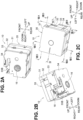
FIG. 2] FIGS. 2A, 2B and 2C are schematic perspective views of the print cassette in the printing apparatus ofFIG. 1A . - [
FIG. 3] FIG. 3 is a schematic exploded perspective view of the print cassette ofFIG. 2A . - [
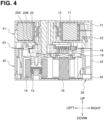
FIG. 4] FIG. 4 is a schematic cross-sectional view taken along line IV-IV ofFIG. 2C . - [
FIG. 5] FIG. 5 is a schematic perspective view illustrating a state of the print cassette ofFIG. 2C from which a first lid portion is detached. - [
FIG. 6] FIG. 6 is a schematic view for explaining a passage of a first tape and an ink ribbon in the print cassette ofFIG. 2A . - [
FIG. 7] FIG. 7A is a schematic cross-sectional view taken along line VIIA-VIIA ofFIG. 2C ,FIG. 7B is a schematic cross-sectional view taken along line VIIB-VIIB ofFIG. 2C ,FIG. 7C is a schematic cross-sectional view taken along line VIIC-VIIC ofFIG. 2C , andFIG. 7D is a schematic cross-sectional view taken along line VIID-VIID ofFIG. 2C . - [
FIG. 8] FIG. 8 is a schematic plan view of the printing apparatus main body in the printing apparatus ofFIG. 1A . - [
FIG. 9] FIG. 9 is a schematic view illustrating an engagement state of an output gear and a platen gear in the printing apparatus ofFIG. 1A . - [
FIG. 10] FIGS. 10A and 10B are schematic perspective views illustrating a state in which a print cassette is detached from a printing apparatus main body in a printing apparatus according to an embodiment different fromFIG. 1A . - [
FIG. 11] FIG. 11 is a schematic exploded perspective view of the print cassette in the printing apparatus ofFIG. 10A . - [
FIG. 12] FIG. 12 is a schematic plan view of the printing apparatus main body in the printing apparatus ofFIG. 10A . - [
FIG. 13] FIG. 13 is a schematic view illustrating an engagement state of an output gear and a platen gear in the printing apparatus ofFIG. 10A . - A
printing apparatus 1 illustrated inFIGS. 1A, 1B, and 1C includes aprint cassette 10 and a printing apparatusmain body 100. Theprinting apparatus 1 is an apparatus that performs printing on a tape print medium. - In the present embodiment, an axial direction of an
output gear 18 is an up-down direction, a direction perpendicular to the up-down direction in which theoutput gear 18 and aninput spool 16 are aligned is a front-rear direction, and a direction perpendicular to both the up-down direction and the front-rear direction is a left-right direction. - As illustrated in
FIG. 1B , the printing apparatusmain body 100 includes acassette insertion portion 101, aprint head 102, aplaten roller 103, aplaten gear 104, and adrive shaft 105. - The
cassette insertion portion 101 is a recessed portion to which theprint cassette 10 is attached. Thecassette insertion portion 101 has a function of positioning theprint cassette 10. - The
print head 102 is disposed in an interior of thecassette insertion portion 101. Theprint head 102 has a plurality of heating elements whose heat generation is to be individually controlled. - A rotation axis L1 of the
platen roller 103 is parallel to the up-down direction. Theplaten roller 103 is disposed near theprint head 102 in the interior of thecassette insertion portion 101. Theplaten roller 103 is swingable in a direction toward or away from theprint head 102. - The
platen gear 104 is coupled to theplaten roller 103. In the present embodiment, a rotation axis L2 of theplaten gear 104 is located collinearly with the rotation axis L1 of theplaten roller 103. Theplaten gear 104 is swingable together with theplaten roller 103. - The
drive shaft 105 is inserted into theinput spool 16. Thedrive shaft 105 rotates theinput spool 16. - The
drive shaft 105 is disposed in the interior of thecassette insertion portion 101. A rotation axis L3 of thedrive shaft 105 is parallel to the up-down direction. Thedrive shaft 105 is rotated about the rotation axis L3 by a drive source (for example, a motor), which is not illustrated. - The
print cassette 10 houses a print medium. Theprint cassette 10 is attachable to and detachable from the printing apparatusmain body 100. By replacing theprint cassette 10, a print medium can be supplied and the type (for example, color, material, etc.) of print medium can be changed. - As illustrated in
FIGS. 2A, 2B, and 2C , theprint cassette 10 includes acase 35 that houses afirst tape 11A, an ink ribbon (an example of a second tape) 14A, and the like. The outer shape of the print cassette 10 (i.e., the shape of the case 35) is a rectangular parallelepiped having sides parallel to the up-down direction, sides parallel to the front-rear direction, and sides parallel to the left-right direction. Thecase 35 has afirst lid portion 31, afirst frame portion 32, asecond frame portion 33, and asecond lid portion 34. - As illustrated in
FIG. 3 , theprint cassette 10 includes afirst roll 11, afirst supply spool 12,spacer films second roll 14, asecond supply spool 15, theinput spool 16, aclutch spring holder 17, anoutput gear 18, aninput gear 19, and anidle gear 20. - In the
first roll 11, afirst tape 11A on which printing is to be performed is wound around thefirst supply spool 12. Printing is performed on thefirst tape 11A by theprint head 102 of the printing apparatusmain body 100 and theink ribbon 14A. - Two
spacer films first roll 11 in the up-down direction in such a manner as to sandwich thefirst roll 11. Thespacer film 13A is disposed between thefirst roll 11 and thefirst lid portion 31 and thespacer film 13B is disposed between thefirst roll 11 and thefirst frame portion 32. - The
first supply spool 12 is rotatable about a rotation axis L4. Thefirst supply spool 12 rotates along with theplaten roller 103 of the printing apparatusmain body 100 conveying thefirst tape 11A, thereby supplying thefirst tape 11A to theprint head 102. - In the
second roll 14, theink ribbon 14A used for printing on thefirst tape 11A is wound around thesecond supply spool 15. - The
ink ribbon 14A is superimposed on thefirst tape 11A in thehead opening 33B and is supplied for printing by theprint head 102. Theink ribbon 14A used for printing is taken up by theinput spool 16. Thesecond roll 14 is subjected to rotation pressure applied by a clutch spring held by aclutch spring holder 17. At least a portion of thesecond roll 14 is disposed at a position overlapping thefirst roll 11 in the up-down direction. - The
second supply spool 15 is rotatable about a rotation axis L5. The rotation axis L5 of thesecond supply spool 15 is parallel to the rotation axis L4 of thefirst supply spool 12, that is, parallel to the up-down direction. - The
second supply spool 15 rotates along with theinput spool 16 taking up theink ribbon 14A, thereby supplying theink ribbon 14A to theprint head 102. - The
input spool 16 is rotatable about a rotation axis L6. The rotation axis L6 of theinput spool 16 is parallel to the rotation axis L5 of thesecond supply spool 15. - The
input spool 16 is cylindrical and has an innerperipheral surface 16A defining a hollow portion. The innerperipheral surface 16A of theinput spool 16 is provided withspline teeth 16B. Adrive shaft 105 of the printing apparatusmain body 100 is coupled to thespline teeth 16B. Theinput spool 16 is rotated by thedrive shaft 105. - The
output gear 18 is a gear for outputting a driving force for conveying thefirst tape 11A to the outside. Specifically, theoutput gear 18 outputs a driving force to theplaten gear 104 of the printing apparatusmain body 100. - The
output gear 18 is a single gear having a first side surface and a second side surface perpendicular to a rotation axis L7. The rotation axis L7 of theoutput gear 18 is parallel to the rotation axis L5 of thesecond supply spool 15. Further, in an axial direction of the rotation axis L5 of the second supply spool 15 (i.e., the up-down direction), the first side surface is located at a position closer to thefirst roll 11 than the second side surface is. The entire region of the first side surface overlaps acover portion 32B in the up-down direction. - The
output gear 18 is partially exposed to thehead opening 33B. Theoutput gear 18 engages theplaten gear 104 at thehead opening 33B in a state in which theprint cassette 10 is attached to the printing apparatusmain body 100. - As illustrated in
FIG. 4 , thesecond supply spool 15, theoutput gear 18, and thefirst roll 11 are disposed in order of thesecond supply spool 15, theoutput gear 18, and thefirst roll 11 in the up-down direction. That is, theoutput gear 18 is positioned between thesecond supply spool 15 and thefirst roll 11 in the up-down direction. - As illustrated in
FIG. 3 , theinput gear 19 is a gear that indirectly engages theoutput gear 18 via anidle gear 20 to transmit a driving force to theoutput gear 18. - The
input gear 19 includes agear 19A and acylindrical spool 19B fixed to one side surface of thegear 19A and having spline teeth on an inner peripheral surface thereof. Thegear 19A is rotated integrally with thespool 19B by the driving force input to thespool 19B. - A rotation axis L8 of the input gear 19 (i.e., a rotational axis of the
gear 19A and a rotation axis of thespool 19B) is located collinearly with the rotation axis L6 of theinput spool 16. As illustrated inFIG. 4 , theinput spool 16, theinput gear 19, and thefirst roll 11 are disposed in order of theinput spool 16, theinput gear 19, and thefirst roll 11 in the up-down direction. - That is, the
input gear 19 is positioned between theinput spool 16 and thefirst roll 11 in the up-down direction. At least a portion of theinput gear 19 is located at a position overlapping thefirst roll 11 in the up-down direction. - The rotation axis L8 of the
input gear 19 overlaps the hollow portion of theinput spool 16 in the up-down direction. Thedrive shaft 105 is thus simultaneously inserted through theinput spool 16 and theinput gear 19. As a result, although not directly coupled to theinput spool 16, theinput gear 19 is rotated by a common drive source (i.e., the drive shaft 105) with theinput spool 16. - The
idle gear 20 engages theinput gear 19 and theoutput gear 18. Theidle gear 20 constitutes a transmission mechanism to transmit the driving force input to theinput gear 19 to theoutput gear 18. - The
idle gear 20 is a stepped gear in which afirst gear 20A engaged with theinput gear 19 and asecond gear 20B engaged with theoutput gear 18 are disposed coaxially. Thesecond gear 20B has a smaller diameter than thefirst gear 20A has. Further, thesecond gear 20B is disposed at a position closer to thefirst roll 11 than thefirst gear 20A is in the up-down direction (i.e., at a position upper than thefirst gear 20A). Theidle gear 20 constitutes a speed reduction mechanism that reduces the rotational speed of the driving force input to theinput gear 19. - As illustrated in
FIG. 3 , thefirst lid portion 31 constitutes an upper end portion of theprint cassette 10. Thefirst frame portion 32 is disposed below thefirst lid portion 31 and connected to thefirst lid portion 31 in the up-down direction. Thesecond frame portion 33 is disposed below thefirst frame portion 32 and connected to thefirst frame portion 32 in the up-down direction. Thesecond lid portion 34 constitutes a lower end portion of theprint cassette 10. Thesecond lid portion 34 is connected to thesecond frame portion 33 in the up-down direction. - The
first lid portion 31 and thefirst frame portion 32 constitute afirst case portion 41 that houses thefirst roll 11. That is, thefirst roll 11 is disposed in a space surrounded by thefirst lid portion 31 and thefirst frame portion 32. - The
second lid portion 34 and thesecond frame portion 33 constitute asecond case portion 42 that houses thesecond roll 14, thesecond supply spool 15, and theinput spool 16. That is, thesecond roll 14, thesecond supply spool 15, and theinput spool 16 are disposed in a space surrounded by thesecond lid portion 34 and thesecond frame portion 33. - The
first frame portion 32 and thesecond frame portion 33 constitute athird case portion 43 in which a portion of theoutput gear 18, theinput gear 19, and theidle gear 20 are disposed. That is, a portion of theoutput gear 18, theinput gear 19, and theidle gear 20 are disposed in a space surrounded by thefirst frame portion 32 and thesecond frame portion 33. Thethird case portion 43 is disposed between thefirst case portion 41 and thesecond case portion 42 in the up-down direction. - The
first frame portion 32 includes afirst sidewall 32A, acover portion 32B, afirst guide 32C, a firstgear support portion 32D, a secondgear support portion 32E, and a thirdgear support portion 32F. Thefirst sidewall 32A constitutes a side surface parallel to the up-down direction of theprint cassette 10. Thecover portion 32B has a surface perpendicular to the up-down direction. - The
cover portion 32B is disposed at a position overlapping theoutput gear 18 in the up-down direction. In the present embodiment, thecover portion 32B is provided continuously with a lower end portion of thefirst sidewall 32A and is disposed at a right front corner portion of thefirst frame portion 32. - The
output gear 18, thecover portion 32B, and thefirst roll 11 are disposed in order of theoutput gear 18, thecover portion 32B, and thefirst roll 11 in the up-down direction. As described above, the entire region of the first side surface (i.e., the upper side surface) of theoutput gear 18 overlaps thecover portion 32B in the up-down direction. - As illustrated in
FIG. 5 , thefirst guide 32C is a portion around which thefirst tape 11A pulled out from thefirst roll 11 is wound. Thefirst guide 32C has a plurality of plate-shaped ribs spaced apart from each other in a circumferential direction of thefirst roll 11. Each of the ribs protrudes in a radial direction of thefirst roll 11, and a protrusion amount (i.e., a plate width) increases downward. - The first
gear support portion 32D illustrated inFIG. 3 rotatably supports theoutput gear 18. The secondgear support portion 32E rotatably supports theinput gear 19. The thirdgear support portion 32F rotatably supports theidle gear 20. - The
second frame portion 33 has asecond sidewall 33A, thehead opening 33B, adischarge port 33C, asecond guide 33D, and anexit 33E. Thesecond sidewall 33A constitutes a side surface parallel to the up-down direction of theprint cassette 10. - The
head opening 33B is a portion missing from thesecond sidewall 33A. In a state in which theprint cassette 10 is attached to the printing apparatusmain body 100, thehead opening 33B is a space in which theprint head 102 inserted from below is disposed. Thehead opening 33B is open downward in theprint cassette 10. - The
second guide 33D is a portion around which thefirst tape 11A having passed through thefirst guide 32C is wound. Similarly to thefirst guide 32C, thesecond guide 33D has a plurality of plate-shaped ribs spaced apart from each other in a circumferential direction of thesecond roll 14. Each of the ribs protrudes in a radial direction of thefirst roll 14, and a protrusion amount (i.e., a plate width) increases downward. - The
exit 33E is a portion where thefirst tape 11A pulled out from thefirst roll 11 is discharged to thehead opening 33B. That is, theexit 33E communicates with thehead opening 33B. In addition, theexit 33E, theoutput gear 18, and thefirst roll 11 are disposed in order of theexit 33E, theoutput gear 18, and thefirst roll 11 in the up-down direction. - As illustrated in
FIG. 6 , thefirst tape 11A and theink ribbon 14A are laid across thehead opening 33B in the left-right direction. The printedfirst tape 11A is discharged from thedischarge port 33C outside theprinting apparatus 1. - The
head opening 33B and thedischarge port 33C are part of thesecond case portion 42. A portion of theoutput gear 18 is located in thehead opening 33B. Thecover portion 32B is exposed in thehead opening 33B. - As illustrated in
FIGS. 7A, 7B, 7C, and 7D , thefirst guide 32C and thesecond guide 33D constitute a passage through which thefirst tape 11A constituting thefirst roll 11 is fed from thefirst case portion 41 to thesecond case portion 42. - Specifically, as illustrated in
FIG. 7A , thefirst tape 11A pulled out from thefirst roll 11 is conveyed in a spiral downward to the rear in thefirst case portion 41 while coming into contact with thefirst guide 32C from the outside of thefirst roll 11 in the radial direction. As illustrated inFIG. 7B , thefirst tape 11A is further conveyed downward to the left across thethird case portion 43 in the up-down direction. - As illustrated in
FIG. 7C , thefirst tape 11A that has reached thesecond case portion 42 is conveyed downward to the front while coming into contact with thesecond guide 33D from the radially outer side. As illustrated inFIG. 7D , thefirst tape 11A that has reached the lower end portion of theprint cassette 10 passes through thehead opening 33B and is discharged from thedischarge port 33C. - As illustrated in
FIG. 7A , theoutput gear 18 is located in a first region A1 of thecase 35 in a first direction (i.e., the front-rear direction) orthogonal to the up-down direction. In contrast, thefirst tape 11A is diagonally laid in a second region A2 of thecase 35 different from the first region A1 in a direction intersecting with a second direction (i.e., the left-right direction) orthogonal to the up-down direction and the first direction. The first region A1 of the present embodiment is a region in front of the second region A2. - Further, the
first tape 11A is conveyed in the second direction toward thedischarge port 33C in a region of the first region A1 across theoutput gear 18 from thefirst roll 11 in the up-down direction. - The
print head 102 performs printing on thefirst tape 11A held by theprint cassette 10. - In a state in which the
print cassette 10 is attached to the printing apparatusmain body 100, theprint head 102 is disposed at a position overlapping thefirst tape 11A and theink ribbon 14A in the front-rear direction in thehead opening 33B (refer toFIG. 6 ). - The
first tape 11A conveyed to thehead opening 33B by theplaten roller 103 is pressed via theink ribbon 14A against theprint head 102 in which the heating elements generate heat. As a result, a portion of ink disposed on the front face of theink ribbon 14A is transferred to thefirst tape 11A, and characters, symbols, and the like are printed on thefirst tape 11A. - The
platen roller 103 conveys thefirst tape 11A from inside theprint cassette 10 to outside. Theplaten roller 103 abuts against thefirst tape 11A in thehead opening 33B and presses thefirst tape 11A against theprint head 102. - The
platen gear 104 is coupled to theplaten roller 103 and engages theoutput gear 18. Theplaten roller 103 and theplaten gear 104 are swingable between a position illustrated inFIG. 8 where they are separated from theprint cassette 10 and a position illustrated inFIG. 9 where theplaten gear 104 engages theoutput gear 18. - The
drive shaft 105 is inserted into theinput spool 16 and engages theinput gear 19 to rotate theinput spool 16 and theinput gear 19. - As illustrated in
FIG. 9 , in a state where theprint cassette 10 is attached to the printing apparatusmain body 100, thedrive shaft 105 engages theinput gear 19, and theplaten gear 104 engages theoutput gear 18. Specifically, thedrive shaft 105 is inserted into theinput spool 16 and theinput gear 19 of theprint cassette 10. Thereafter, theplaten roller 103 and theplaten gear 104 are swung toward thehead opening 33B of theprint cassette 10. - When the
drive shaft 105 rotates theinput gear 19 in a state where theprint cassette 10 is attached, theoutput gear 18 is rotated, theplaten gear 104 rotates with the rotation of theoutput gear 18, and theplaten roller 103 rotates with the rotation of theplaten gear 104. - According to the embodiment described above in detail, the following effects are obtained.
- (1a) The
second supply spool 15, theoutput gear 18, and thefirst roll 11 are disposed in order of thesecond supply spool 15, theoutput gear 18, and thefirst roll 11 in the axial direction of the rotation axis L5 of thesecond supply spool 15. - The
print cassette 10 of the present embodiment is assumed to be relatively frequently replaced, in theprinting apparatus 1, with one of various types ofprint cassettes 10 each storing a different type of tape having a different color, shape, or the like. For this reason, aprint cassette 10 may be dropped when replaced. - In contrast, even when the
print cassette 10 is dropped and collides with something like a floor surface, due to the arrangement of thesecond supply spool 15, theoutput gear 18, and thefirst roll 11 described above, a portion of theprint cassette 10 in the up-down direction closer to thesecond supply spool 15 or thefirst roll 11 may be highly likely to collide with the floor surface earlier than theoutput gear 18. Therefore, the probability of theoutput gear 18 colliding with the floor surface can be reduced. As a result, damage to theoutput gear 18 is reduced when a surface perpendicular to the axial direction of the rotation axis L5 of thesecond supply spool 15 collides with something like a floor surface. - (1b) The above-described arrangement facilitates alignment of the
output gear 18 in the axial direction of the rotational axis L5 of thesecond supply spool 15 when theprint cassette 10 is attached to the printing apparatusmain body 100. This reduces a failure in engaging theoutput gear 18 and theplaten gear 104. - (1c) With the above-described arrangement, the
first tape 11A and theink ribbon 14A can be spaced from each other inside theprint cassette 10. This reduces interference between components of thefirst tape 11A and components of theink ribbon 14A. - (1d) In the above-described arrangement, since the rotation axis L7 of the
output gear 18 and the rotation axis L8 of theinput gear 19 are misaligned with each other, the design flexibility of theprint cassette 10 increases. - (1e) With the above-described arrangement, interference between the
output gear 18 and the conveyance passage of thefirst tape 11A in thehead opening 33B can be avoided. This increases the design flexibility of theprint cassette 10. - (1f) With the above-described arrangement, the
output gear 18 is disposed more inward than thesecond supply spool 15 in the axial direction of the rotation axis L5, and thus the strength of the support portion (i.e., the first frame portion 32) of theoutput gear 18 can be increased. - (1g) Since the
input spool 16, theinput gear 19, and thefirst roll 11 are disposed in order of theinput spool 16, theinput gear 19, and thefirst roll 11 in the axial direction of the rotation axis L5 of thesecond supply spool 15, when theprint cassette 10 is dropped and a surface perpendicular to the axial direction of the rotation axis L5 of thesecond supply spool 15 collides with something like a floor surface, damage to theinput gear 19 is reduced. - (1h) The
output gear 18, thecover portion 32B, and thefirst roll 11 are disposed in order of theoutput gear 18, thecover portion 32B, and thefirst roll 11 in the axial direction of the rotation axis L5 of thesecond supply spool 15. As described above, in the present embodiment, theprint cassette 10 may be dropped, for example, when theprint cassette 10 is replaced. - In contrast, even when the
print cassette 10 falls, as thecover portion 32B is provided, the probability that thecover portion 32B, not theoutput gear 18, collides with something like a floor surface is increased. Theoutput gear 18 is thus protected by thecover portion 32B, and damage to theoutput gear 18 is further reduced. - (1i) The
idle gear 20 can reduce the rotation speed of the driving force of thedrive shaft 105 to a rotation speed suitable for conveying thefirst tape 11A. Therefore, conveyance of thefirst tape 11A and supply of theink ribbon 14A can be performed using a common drive source. - (1j) The
first tape 11A is diagonally laid in the second region A2 in a direction intersecting the second direction, and is conveyed toward thedischarge port 33C in a region of the first region A1 across theoutput gear 18 from thefirst roll 11 in the axial direction of the rotation axis L5 of thesecond supply spool 15. Thus, theprint cassette 10 can be downsized. - A
printing apparatus 1A illustrated inFIGS. 10A and 10B includes aprint cassette 10A and a printing apparatusmain body 100A. - In the
print cassette 10A, athird roll 21, a take-upspool 22, a take-up gear 23, and apinch roller 24 illustrated inFIG. 11 are added to theprint cassette 10 of the first embodiment, and theinput spool 16, thefirst lid portion 31, thefirst frame portion 32, thesecond frame portion 33, and thesecond lid portion 34 of the first embodiment are replaced with aninput spool 25, afirst lid portion 36, afirst frame portion 37, asecond frame portion 38, and asecond lid portion 39. - The
input spool 25 is similar to theinput spool 16 except that it does not havespline teeth 16B. Thefirst lid portion 36, thefirst frame portion 37, thesecond frame portion 38, and thesecond lid portion 39 are extended in the left-right direction more than thefirst lid portion 31, thefirst frame portion 32, thesecond frame portion 33, and thesecond lid portion 34, respectively. Other configurations of theprint cassette 10A are similar to those of theprint cassette 10 of the first embodiment except for the points described below, and thus description thereof will be omitted. - In the
third roll 21, a laminate tape used for protecting thefirst tape 11A is wound around theinput spool 25. The laminate tape has an adhesive surface to be bonded to thefirst tape 11A on which printing has been performed by theprint head 102. - The take-up
spool 22 is rotatable about a rotation axis L9. The rotation axis L9 of the take-upspool 22 is parallel to the rotation axis L5 of thesecond supply spool 15, that is, parallel to the up-down direction. The take-upspool 22 takes up theink ribbon 14A by rotation of the take-up gear 23. - The take-
up gear 23 is coupled to the take-upspool 22 and engaged with theidle gear 20. The take-up gear 23 is rotated by the driving force input to theinput gear 19 to rotate the take-upspool 22. - The
pinch roller 24 presses the laminate tape against the printedfirst tape 11A together with thepressing roller 106. Thepinch roller 24 is disposed downstream of thehead opening 33B in the conveyance direction of thefirst tape 11A. - In the printing apparatus
main body 100A, apressing roller 106 illustrated inFIG. 12 is added to the printing apparatusmain body 100 of the first embodiment. Other configurations of the printing apparatusmain body 100A are similar to those of the printing apparatusmain body 100 of the first embodiment except for the points described below, and thus description thereof will be omitted. - The
pressing roller 106 is configured to be swingable together with theplaten roller 103 and theplaten gear 104. Thepressing roller 106 is swingable between a position illustrated inFIG. 12 where it is separated from theprint cassette 10A and a position illustrated inFIG. 13 where it presses thefirst tape 11A and the laminate tape together with thepinch roller 24. - According to the embodiment described above in detail, the following effects are obtained.
- (2a) The printed content on the
first tape 11A can be protected by the laminate tape while having the same advantages as those of the first embodiment. - Although the embodiments of the present disclosure have been described above, it is needless to say that the present disclosure is not limited to the above-described embodiments and can take various forms.
- (3a) The printing apparatus of each embodiment described above is not limited to an apparatus that performs printing using an ink ribbon as a second tape. The printing apparatus may use a band-shaped thermal paper instead of the first tape in the first embodiment, and may use a laminate tape (i.e., a protective tape) instead of the ink ribbon.
- In addition, the printing apparatus may use, as the first tape, a stencil tape on which a printing pattern is perforated by a thermal head, and may use, as the second tape, a band-shaped slip sheet that protects and supports the stencil tape. In this case, in the head opening, the first tape may be superimposed on the second tape at a position closer to the print head than the second tape (i.e., as an upper layer), or the first tape may be superimposed on the second tape at a position farther from the print head than the second tape (i.e., as a lower layer).
- (3b) The print cassette according to each embodiment described above may have two or more idle gears. Further, the transmission mechanism that engages the input gear and the output gear does not necessarily include a speed reduction mechanism. That is, the idle gear does not necessarily have to be a stepped gear and may be a single spur gear. Further, the print cassette may have a transmission mechanism other than a gear. Further, the print cassette may not have the transmission mechanism itself, and the output gear may directly engage the input gear.
- (3c) In the print cassette of each embodiment described above, the conveyance passage of the first tape is an example. Therefore, the first tape does not necessarily need to be diagonally laid in the second region in a direction intersecting the second direction. The direction in which the first tape is discharged may be other than the second direction.
- (3d) The print cassette according to the second embodiment may include a third supply spool around which a laminate tape is wound, instead of the take-up spool. In the print cassette according to the second embodiment, the input spool may be used as a take-up spool for an ink ribbon.
- (3e) The functions of one component in each embodiment described above may be distributed as a plurality of components, or the functions of a plurality of components may be integrated into one component. Further, a portion of the configuration of each embodiment described above may be omitted. In addition, at least a portion of the configuration of each embodiment described above may be added to or replaced with another configuration thereof. It should be noted that all aspects included in the technical idea specified by the wording described in the claims are embodiments of the present disclosure.
-
- 1, 1A
- printing apparatus main body
- 10, 10A
- print cassette
- 11
- first roll
- 11A
- first tape
- 12
- first supply spool
- 14
- second roll
- 14A
- ink ribbon
- 15
- second supply spool
- 16
- input spool
- 18
- output gear
- 19
- input gear
- 20
- idle gear
- 20A
- first gear
- 20B
- second gear
- 21
- third roll
- 22
- take-up spool
- 23
- take-up gear
- 31
- first lid portion
- 32
- first frame portion
- 32B
- cover portion
- 33
- second lid portion
- 33B
- head opening
- 33C
- discharge port
- 33E
- exit
- 34
- second lid portion
- 35
- case
- 41
- first case portion
- 42
- second case portion
- 43
- third case portion
- 100, 100A
- printing apparatus main body
- 101
- cassette insertion portion
- 102
- print head
- 103
- platen roller
- 104
- platen gear
- 105
- drive shaft
- Certain aspects and/or embodiments of the present disclosure are as follows:
- 1. A printing apparatus comprising:
- a printing apparatus main body; and
- a print cassette attachable to and detachable from the printing apparatus main body, the print cassette including:
- a roll of a first tape;
- a supply spool rotatable about a rotation axis;
- a second tape wound around the supply spool and used for printing or protecting of the first tape;
- an output gear to output a driving force outside;
- an input spool rotatable about a rotation axis; and
- an input gear directly or indirectly engaging the output gear to transmit the driving force to the output gear,
- wherein a rotation axis of the input gear is located collinearly with the rotation axis of the input spool,
- wherein the input spool, the input gear, and the roll are disposed in order of the input spool, the input gear, and the roll in an axial direction of the rotation axis of the supply spool,
- wherein the supply spool, the output gear, and the roll are disposed in order of the supply spool, the output gear, and the roll in the axial direction of the rotation axis of the supply spool,
- wherein the printing apparatus main body includes:
- a print head to print on the first tape;
- a platen roller to convey the first tape;
- a platen gear coupled to the platen roller to engage the output gear; and
- a drive shaft to engage the input gear when inserted in the input spool to rotate the input spool and the input gear, and
- wherein, in a state where the print cassette is attached to the printing apparatus main body, the drive shaft engages the input gear and the platen gear engages the output gear, when the drive shaft rotates the input gear, the output gear is rotated, the platen gear rotates with rotation of the output gear, and the platen roller rotates with rotation of the platen gear.
- 2. A print cassette, comprising:
- a roll of a first tape;
- a supply spool rotatable about a rotation axis;
- a second tape wound around the supply spool and used for printing or protecting of the first tape; and
- an output gear to output a driving force outside,
- wherein the supply spool, the output gear, and the roll are disposed in order of the supply spool, the output gear, and the roll in an axial direction of the rotation axis of the supply spool.
- 3. The print cassette according to claim 2, further comprising a case in which at least a portion of the roll, at least a portion of the supply spool, at least a portion of the second tape, and at least a portion of the output gear are disposed.
- 4. The print cassette according to aspect 3,
- wherein the case has a cover portion disposed at a position overlapping the output gear in the axial direction of the rotation axis of the supply spool, and
- wherein the output gear, the cover portion, and the roll are disposed in order of the output gear, the cover portion, and the roll in the axial direction of the rotation axis of the supply spool.
- 5. The print cassette according to any one of aspects 2 to 4, further comprising:
- an input spool rotatable about a rotation axis; and
- an input gear directly or indirectly engaging the output gear to transmit the driving force to the output gear,
- wherein a rotation axis of the input gear is located collinearly with the rotation axis of the input spool, and
- wherein the input spool, the input gear, and the roll are disposed in the order of the input spool, the input gear, and the roll in the axial direction of the rotation axis of the supply spool.
- 6. The print cassette according to aspect 5,
- wherein the input spool is cylindrical,
- wherein the input spool has an inner peripheral surface defining a hollow portion,
- wherein the inner peripheral surface of the input spool is provided with spline teeth, and
- wherein the rotation axis of the input gear overlaps the hollow portion in a direction of the rotation axis of the input spool.
- 7. The print cassette according to aspect 5 or 6, wherein at least a portion of the input gear is located at a position overlapping the roll in the axial direction of the rotation axis of the supply spool.
- 8. The print cassette according to any one of aspects 5 to 7, further comprising a transmission mechanism to engage the input gear and the output gear and transmit a driving force input to the input gear to the output gear.
- 9. The print cassette according to aspect 8, wherein the transmission mechanism has an idle gear.
- 10. The print cassette according to aspect 8 or 9, wherein the transmission mechanism includes a speed reduction mechanism.
- 11. The print cassette according to
aspect 10, wherein the transmission mechanism has a stepped gear in which a plurality of gears are disposed coaxially. - 12. The print cassette according to aspect 9,
- wherein the idle gear engages the output gear, and
- wherein the idle gear is a stepped gear in which a plurality of gears are disposed coaxially.
- 13. The print cassette according to aspect 4,
- wherein the output gear has a first side surface and a second side surface,
- wherein the first side surface is located at a position closer to the roll than the second side surface is in the axial direction of the rotation axis of the supply spool, and
- wherein an entire region of the first side surface overlaps the cover portion in the axial direction of the rotation axis of the supply spool.
- 14. The print cassette according to any one of aspects 2 to 13, wherein at least a portion of a second roll of the second tape wound around the supply spool is located at a position overlapping the roll in the axial direction of the rotation axis of the supply spool.
- 15. The print cassette according to any one of aspects 2 to 14, wherein the output gear is a single gear.
- 16. The print cassette according to aspect 3 or 4,
- wherein the case has a first case portion to house the roll, a second case portion to house the supply spool, and a passage to convey the first tape constituting the roll from the first case portion to the second case portion, and
- wherein the second case portion has a discharge port from which the first tape is discharged outside.
- 17. The print cassette according to
aspect 16,- wherein the case further has a third case portion located between the first case portion and the second case portion, and
- wherein at least a portion of the output gear is located in the third case portion.
- 18. The print cassette according to
aspect - wherein the stepped gear has a first gear and a second gear having a diameter smaller than that of the first gear, and
- wherein the second gear is disposed at a position closer to the roll than the first gear is in the axial direction of the rotation axis of the supply spool.
- 19. The print cassette according to
aspect - wherein the output gear is disposed in a first region of the case in a first direction perpendicular to the axial direction of the rotation axis of the supply spool,
- wherein the first tape is diagonally laid in a direction intersecting a second direction perpendicular to the axial direction of the rotation axis of the supply spool, in a second region of the case different from the first region in the first direction, and
- wherein the first tape is conveyed in the second direction toward the discharge portion in a region of the first region across the output gear from the roll in the axial direction of the rotation axis of the supply spool.
- 20. A print cassette attachable to and detachable from a printing apparatus main body, the print cassette, comprising:
- a roll of a first tape;
- a supply spool rotatable about a rotation axis;
- a second tape wound around the supply spool and used for printing or protecting of the first tape;
- an output gear to output a driving force outside;
- an input spool rotatable about a rotation axis; and
- an input gear directly or indirectly engaging the output gear to transmit the driving force to the output gear,
- wherein a rotation axis of the input gear is located collinearly with the rotation axis of the input spool,
- wherein the input spool, the input gear, and the roll are disposed in order of the input spool, the input gear, and the roll in an axial direction of the rotation axis of the supply spool,
- wherein the supply spool, the output gear, and the roll are disposed in order of the supply spool, the output gear, and the roll in the axial direction of the rotation axis of the supply spool,
- wherein the printing apparatus main body includes:
- a print head to print on the first tape;
- a platen roller to convey the first tape;
- a platen gear coupled to the platen roller to engage the output gear; and
- a drive shaft to engage the input gear when inserted in the input spool to rotate the input spool and the input gear, and
- wherein, in a state where the print cassette is attached to the printing apparatus main body, the drive shaft engages the input gear and the platen gear engages the output gear, when the drive shaft rotates the input gear, the output gear is rotated, the platen gear rotates with rotation of the output gear, and the platen roller rotates with rotation of the platen gear.
- 21. A print cassette, comprising:
- a roll of a first tape;
- an output gear rotatable about a rotation axis to output a driving force outside; and
- a case in which at least a portion of the roll and at least a portion of the output gear are located, the case having an exit from which the first tape pulled out from the roll is discharged,
- wherein the exit, the output gear, and the roll are disposed in order of the exit, the output gear, and the roll in an axial direction of the rotation axis of the output gear.
Claims (2)
- A print cassette (10, 10A), comprising:a roll (11) of a first tape (11A);an output gear (18) rotatable about a rotation axis (L7) to output a driving force outside; anda case (35) in which at least a portion of the roll (11) and at least a portion of the output gear (18) are located, the case (35) having an exit (33E) from which the first tape (11A) pulled out from the roll (11) is discharged,wherein the exit (33E), the output gear (18), and the roll (11) are disposed in order of the exit (33E), the output gear (18), and the roll (11) in an axial direction of the rotation axis (L7) of the output gear (18).
- The print cassette (10, 10A) according to claim 1, wherein the output gear (18) is a single gear.
Applications Claiming Priority (3)
| Application Number | Priority Date | Filing Date | Title |
|---|---|---|---|
| JP2019178912A JP7327059B2 (en) | 2019-09-30 | 2019-09-30 | Printer and cassette for printing |
| EP20872473.2A EP4023452B1 (en) | 2019-09-30 | 2020-09-15 | Printing device and printing cassette |
| PCT/JP2020/034864 WO2021065465A1 (en) | 2019-09-30 | 2020-09-15 | Printing device and printing cassette |
Related Parent Applications (2)
| Application Number | Title | Priority Date | Filing Date |
|---|---|---|---|
| EP20872473.2A Division-Into EP4023452B1 (en) | 2019-09-30 | 2020-09-15 | Printing device and printing cassette |
| EP20872473.2A Division EP4023452B1 (en) | 2019-09-30 | 2020-09-15 | Printing device and printing cassette |
Publications (1)
| Publication Number | Publication Date |
|---|---|
| EP4556251A1 true EP4556251A1 (en) | 2025-05-21 |
Family
ID=75269389
Family Applications (2)
| Application Number | Title | Priority Date | Filing Date |
|---|---|---|---|
| EP20872473.2A Active EP4023452B1 (en) | 2019-09-30 | 2020-09-15 | Printing device and printing cassette |
| EP24222864.1A Pending EP4556251A1 (en) | 2019-09-30 | 2020-09-15 | Printing device and printing cassette |
Family Applications Before (1)
| Application Number | Title | Priority Date | Filing Date |
|---|---|---|---|
| EP20872473.2A Active EP4023452B1 (en) | 2019-09-30 | 2020-09-15 | Printing device and printing cassette |
Country Status (8)
| Country | Link |
|---|---|
| US (2) | US12491723B2 (en) |
| EP (2) | EP4023452B1 (en) |
| JP (3) | JP7327059B2 (en) |
| CN (3) | CN120363612A (en) |
| CA (1) | CA3156078A1 (en) |
| ES (1) | ES3012333T3 (en) |
| PL (1) | PL4023452T3 (en) |
| WO (1) | WO2021065465A1 (en) |
Families Citing this family (8)
| Publication number | Priority date | Publication date | Assignee | Title |
|---|---|---|---|---|
| JP7322640B2 (en) | 2019-09-30 | 2023-08-08 | ブラザー工業株式会社 | printing cassette |
| JP7306197B2 (en) | 2019-09-30 | 2023-07-11 | ブラザー工業株式会社 | Printer and cassette for printing |
| USD989170S1 (en) * | 2020-12-17 | 2023-06-13 | Liling Bao | Label printer cassette |
| JP7593152B2 (en) * | 2021-01-29 | 2024-12-03 | ブラザー工業株式会社 | Auxiliary tape cassette, printing tape cassette and printing cassette |
| JP7665993B2 (en) * | 2021-01-29 | 2025-04-22 | ブラザー工業株式会社 | Printing cassette and printing device |
| JP7655034B2 (en) | 2021-03-24 | 2025-04-02 | ブラザー工業株式会社 | Printing cassette and printing device |
| JP2026062340A (en) * | 2024-09-30 | 2026-04-09 | ブラザー工業株式会社 | Tape cassette |
| JP2026062339A (en) * | 2024-09-30 | 2026-04-09 | ブラザー工業株式会社 | Tape cassette |
Citations (2)
| Publication number | Priority date | Publication date | Assignee | Title |
|---|---|---|---|---|
| US6132120A (en) * | 1995-03-29 | 2000-10-17 | Brother Kogyo Kabushiki Kaisha | Tape-shaped label printing device |
| US8162553B2 (en) * | 2004-08-10 | 2012-04-24 | Dymo | Cassettte locking and ejecting arrangement |
Family Cites Families (112)
| Publication number | Priority date | Publication date | Assignee | Title |
|---|---|---|---|---|
| JPS4912175B1 (en) * | 1969-02-28 | 1974-03-22 | ||
| US3639697A (en) * | 1969-02-28 | 1972-02-01 | Sony Corp | Magnetic tape cartridge containing engaging means for rotary head |
| SE364584B (en) | 1970-04-13 | 1974-02-25 | Canon Kk | |
| JPS5036734B1 (en) | 1970-04-13 | 1975-11-27 | ||
| US3672603A (en) | 1970-06-26 | 1972-06-27 | Cartridge Television Inc | Tape cartridge |
| US3804227A (en) | 1972-05-03 | 1974-04-16 | Scm Corp | Typewriter ribbon cartridge |
| US3948382A (en) | 1973-01-29 | 1976-04-06 | The Singer Company | Data terminal printing assembly |
| US4034935A (en) | 1975-11-19 | 1977-07-12 | Xerox Corporation | Dual level ribbon cartridge |
| CA1119549A (en) | 1978-01-30 | 1982-03-09 | Collier M. Miller | Ribbon cartridge drive |
| US4252450A (en) | 1978-10-03 | 1981-02-24 | Xerox Corporation | Ribbon drive with spring-loaded idler |
| US4397574A (en) | 1979-10-29 | 1983-08-09 | Ncr Corporation | Reloadable ribbon cassette |
| GB2064476B (en) | 1979-11-29 | 1983-08-10 | Itt Creed | Ink ribbon cassette |
| NL8200181A (en) | 1981-01-31 | 1982-08-16 | Victor Company Of Japan | REGISTER AND / OR REPRODUCER. |
| US4402619A (en) | 1981-03-30 | 1983-09-06 | Kroy, Inc. | Printing apparatus and printing cartridge therefor |
| JPS58122887A (en) | 1982-01-18 | 1983-07-21 | Silver Seiko Ltd | Motor driver for typewriter |
| JPS58141479A (en) | 1982-02-15 | 1983-08-22 | Canon Inc | Cassette |
| JPS58175949U (en) | 1982-05-20 | 1983-11-25 | 大和製衡株式会社 | label printer |
| FR2528929B1 (en) | 1982-06-17 | 1988-04-08 | Sagem | IMPROVEMENTS IN MECHANICAL DEVICES FOR SELECTIVE DRIVING OF AT LEAST TWO SHAFTS DRIVEN FROM A SINGLE DRIVING SHAFT, IN PARTICULAR FOR THE LONGITUDINAL MOVEMENT OF AN INK RIBBON IN A PRINTING MACHINE |
| JPS5995180A (en) | 1982-11-22 | 1984-06-01 | Matsushita Electric Ind Co Ltd | ink ribbon cassette |
| US4490059A (en) | 1983-05-04 | 1984-12-25 | Wordex | Ribbon metering device |
| US4856921A (en) | 1983-06-28 | 1989-08-15 | Alps Electric Co., Ltd. | Rotary wheel printer |
| JPS609657U (en) | 1983-07-01 | 1985-01-23 | アルプス電気株式会社 | printer |
| JPS608072U (en) | 1983-06-30 | 1985-01-21 | アルプス電気株式会社 | printer |
| DE3424045A1 (en) | 1983-06-30 | 1985-01-03 | Alps Electric Co., Ltd., Tokio/Tokyo | TYPE WHEEL PRINTER |
| JPS6024565U (en) * | 1983-07-27 | 1985-02-19 | 株式会社東芝 | thermal transfer printer |
| JPS6036255U (en) | 1983-08-22 | 1985-03-13 | 日本電産コパル株式会社 | Thermal transfer serial printer |
| JPS6046254U (en) | 1983-09-06 | 1985-04-01 | アルプス電気株式会社 | ribbon cassette |
| JPS6048456U (en) | 1983-09-12 | 1985-04-05 | 株式会社東芝 | thermal transfer printer |
| JPH0227613B2 (en) | 1984-03-08 | 1990-06-19 | Teraoka Seiko Kk | DENSHIHAKARY OPURINTA |
| US4598780A (en) | 1984-03-02 | 1986-07-08 | Teraoka Seiko Co., Ltd. | Electronic scale printer |
| JPS60224571A (en) | 1984-04-20 | 1985-11-08 | Canon Inc | Transfer recording device |
| US4668961A (en) | 1984-04-20 | 1987-05-26 | Canon Kabushiki Kaisha | Recording apparatus |
| JPS61154877A (en) | 1984-12-27 | 1986-07-14 | Matsushita Electric Ind Co Ltd | Ribbon cassette |
| JPS63156762U (en) | 1987-04-02 | 1988-10-14 | ||
| US4832514A (en) | 1988-02-01 | 1989-05-23 | Kroy Inc. | Thermal transfer device and tape-ribbon cartridge therefor |
| JPH029562U (en) | 1988-06-22 | 1990-01-22 | ||
| JPH026173A (en) | 1988-06-27 | 1990-01-10 | Canon Inc | ribbon feeding device |
| JPH0211379A (en) | 1988-06-30 | 1990-01-16 | Canon Inc | Ink ribbon cassette |
| JPH0211380A (en) | 1988-06-30 | 1990-01-16 | Canon Inc | Ink ribbon cassette |
| US5099378A (en) | 1989-08-24 | 1992-03-24 | Minnesota Mining And Manufacturing Company | Carrier with external interlock for videocassette |
| IT218846Z2 (en) | 1989-11-16 | 1992-11-05 | Incas Holding Spa | NOTARBARTOLO & GERVASI |
| US5234179A (en) | 1990-02-20 | 1993-08-10 | Minnesota Mining And Manufacturing Company | Videotape adaptor for use with a cartridge |
| JPH03284973A (en) | 1990-04-02 | 1991-12-16 | Canon Inc | Ribbon cassette and recording device using same cassette |
| JPH04152176A (en) | 1990-10-16 | 1992-05-26 | Nec Corp | Ink ribbon cassette for printer |
| JPH05139006A (en) | 1990-11-14 | 1993-06-08 | Oki Electric Ind Co Ltd | Film ribbon cassette |
| JPH0553956A (en) | 1991-08-29 | 1993-03-05 | Mitsubishi Electric Corp | System for supporting constitution of computer communication network |
| JPH0541834U (en) | 1991-11-11 | 1993-06-08 | フジコピアン株式会社 | Ink ribbon cassette |
| US5325114A (en) | 1992-09-24 | 1994-06-28 | Pitney Bowes Inc. | Thermal printing postage meter system |
| US5595447A (en) | 1992-10-13 | 1997-01-21 | Seiko Epson Corporation | Tape cartridge and printing device having print medium cartridge |
| JP3341052B2 (en) | 1993-06-28 | 2002-11-05 | カシオ計算機株式会社 | Printing cassette |
| JP2831237B2 (en) | 1993-07-19 | 1998-12-02 | 富士通アイソテック株式会社 | Ink ribbon cassette |
| US5435657A (en) * | 1993-12-28 | 1995-07-25 | Smith Corona Corporation | Label printer and tape and ink ribbon cartridge for use therein |
| JPH07276755A (en) | 1994-04-06 | 1995-10-24 | Casio Comput Co Ltd | Printing cassette and printing device |
| JPH07276757A (en) | 1994-04-11 | 1995-10-24 | Fujicopian Co Ltd | Transfer ribbon cassette |
| US6042280A (en) | 1995-05-25 | 2000-03-28 | Brother Kogyo Kabushiki Kaisha | Tape label printing device |
| US5619244A (en) | 1994-12-27 | 1997-04-08 | Pitney Bowes Inc. | Thermal ink cassette for a thermal printing device |
| JP3160173B2 (en) | 1994-12-28 | 2001-04-23 | アルプス電気株式会社 | Tape printer |
| JP3113532B2 (en) | 1994-12-28 | 2000-12-04 | アルプス電気株式会社 | Tape cassette |
| JPH08183230A (en) | 1994-12-29 | 1996-07-16 | Casio Comput Co Ltd | Printing cassette and printing device |
| US5713677A (en) | 1996-06-25 | 1998-02-03 | Dataproducts Corporation | Ink ribbon cartridge having transfer roller with staggered upper and lower teeth arrangement |
| US5917532A (en) | 1996-11-29 | 1999-06-29 | Pitney Bowes Inc. | Thermal ink ribbon cassette for mailing machines |
| US5959652A (en) | 1997-07-11 | 1999-09-28 | Pitney Bowes Inc. | Thermal ink ribbon cassette for mailing machines |
| JP4035894B2 (en) * | 1998-06-24 | 2008-01-23 | カシオ計算機株式会社 | Tape take-up device |
| US6135657A (en) | 1998-08-07 | 2000-10-24 | Axiohm Transaction Solutions, Inc. | Ribbon cassette with coaxial spools on common shaft with partition for preventing contamination |
| US6190067B1 (en) | 1998-09-21 | 2001-02-20 | Casio Computer., Ltd. | Cassette containing magnetically affixable printing tape |
| JP4174873B2 (en) | 1998-09-29 | 2008-11-05 | ブラザー工業株式会社 | Tape cassette |
| FR2796372B1 (en) | 1999-07-13 | 2001-09-07 | Dassault Automatismes | CONSUMABLE TAPE CASSETTE, ESPECIALLY FOR A DEVICE FOR PROCESSING TRANSPORTATION TITLES |
| JP2001047713A (en) | 1999-08-05 | 2001-02-20 | Fujicopian Co Ltd | Ink ribbon cassette |
| CN1880095B (en) | 1999-08-06 | 2011-11-16 | 兄弟工业株式会社 | Tape supply cartridge |
| JP4452392B2 (en) | 2000-09-29 | 2010-04-21 | セイコーエプソン株式会社 | Tape printer |
| WO2002032680A1 (en) | 2000-10-19 | 2002-04-25 | Brother Kogyo Kabushiki Kaisha | Tape cassette and tape unit |
| DE60144529D1 (en) | 2000-10-19 | 2011-06-09 | Brother Ind Ltd | BAND CASSETTE AND BAND UNIT |
| JP4574869B2 (en) | 2001-01-18 | 2010-11-04 | 日本電産コパル株式会社 | Thermal printer |
| JP2002361962A (en) | 2001-06-11 | 2002-12-18 | Brother Ind Ltd | Printing device and printing medium cartridge |
| GB0230196D0 (en) | 2002-12-24 | 2003-02-05 | Esselte Nv | Identifying compatible combination for a thermal printer |
| EP1575782B1 (en) * | 2002-12-24 | 2015-07-01 | Dymo | Printing device and cassette |
| GB0230200D0 (en) | 2002-12-24 | 2003-02-05 | Esselte Nv | Validation of consumables |
| GB0230199D0 (en) | 2002-12-24 | 2003-02-05 | Esselte Nv | Information on consumables |
| JP2005053182A (en) | 2003-08-07 | 2005-03-03 | Brother Ind Ltd | Tape printing apparatus and tape printing system |
| US7070347B2 (en) | 2003-08-12 | 2006-07-04 | Brady Worldwide, Inc. | Printer with a pivoting gear mechanism |
| JP4379178B2 (en) | 2004-03-29 | 2009-12-09 | ブラザー工業株式会社 | Tape cassette |
| US7484902B2 (en) | 2006-01-24 | 2009-02-03 | Cartec International, Inc. | Ribbon cassette for mailing machine |
| US20080084494A1 (en) | 2006-03-23 | 2008-04-10 | Cartec International, Inc. | Ribbon cassette for mailing machine |
| JP4337902B2 (en) | 2007-04-11 | 2009-09-30 | コニカミノルタビジネステクノロジーズ株式会社 | Toner container and image forming apparatus suitable therefor |
| JP4924212B2 (en) | 2007-06-04 | 2012-04-25 | セイコーエプソン株式会社 | Tape processing unit |
| JP5082916B2 (en) | 2008-02-25 | 2012-11-28 | セイコーエプソン株式会社 | Container and recording device |
| ES2554777T3 (en) | 2008-12-25 | 2015-12-23 | Brother Kogyo Kabushiki Kaisha | Ribbon cartridge and ribbon printer |
| EP2752299B1 (en) | 2008-12-25 | 2018-08-15 | Brother Kogyo Kabushiki Kaisha | Tape cassette and tape printer |
| JP5445582B2 (en) * | 2009-03-31 | 2014-03-19 | ブラザー工業株式会社 | Tape cassette |
| CN104442030B (en) * | 2009-03-31 | 2017-04-12 | 兄弟工业株式会社 | Tape cassette |
| EP3871890B1 (en) | 2009-03-31 | 2024-09-04 | Brother Kogyo Kabushiki Kaisha | Tape cassette and tape printer |
| EP4620691A3 (en) | 2009-03-31 | 2025-10-01 | Brother Kogyo Kabushiki Kaisha | Tape cassette and tape printer |
| GB0907280D0 (en) | 2009-04-28 | 2009-06-10 | Dymo Nv | Cassette for use in a tape printer |
| JP2011046142A (en) * | 2009-08-28 | 2011-03-10 | Brother Industries Ltd | Tape cassette and printer |
| JP5597971B2 (en) | 2009-11-06 | 2014-10-01 | シンフォニアテクノロジー株式会社 | Printer |
| JP5482215B2 (en) | 2010-01-19 | 2014-05-07 | コニカミノルタ株式会社 | Image forming apparatus |
| JP2011148167A (en) | 2010-01-20 | 2011-08-04 | Oki Data Corp | Ink ribbon cartridge |
| JP5607971B2 (en) * | 2010-03-31 | 2014-10-15 | サトーホールディングス株式会社 | Printer for ink ribbon cassette and printer for ink ribbon cassette |
| JP2012135931A (en) | 2010-12-27 | 2012-07-19 | Canon Inc | Ink ribbon cassette |
| CN102092201B (en) | 2011-01-10 | 2012-03-07 | 珠海天威飞马打印耗材有限公司 | Ribbon cartridge |
| JP5793339B2 (en) | 2011-05-11 | 2015-10-14 | フジコピアン株式会社 | Ink ribbon cassette of printing device |
| JP5234200B2 (en) | 2012-03-12 | 2013-07-10 | ブラザー工業株式会社 | Tape cassette and tape printer |
| JP2014145794A (en) | 2013-01-25 | 2014-08-14 | Brother Ind Ltd | Developing device |
| JP6160126B2 (en) | 2013-03-04 | 2017-07-12 | ブラザー工業株式会社 | Developer cartridge |
| CN103273748B (en) | 2013-06-07 | 2015-09-30 | 红石电脑(上海)有限公司 | Color ribbon cartridge |
| EP3124257B1 (en) * | 2014-03-24 | 2019-03-13 | Seiko Epson Corporation | Tape printing apparatus and tape printing system |
| JP6113207B2 (en) | 2014-03-24 | 2017-04-12 | セイコーエプソン株式会社 | Tape cartridge |
| JP6486599B2 (en) | 2014-03-24 | 2019-03-20 | セイコーエプソン株式会社 | Tape cartridge |
| JP6528383B2 (en) | 2014-10-23 | 2019-06-12 | セイコーエプソン株式会社 | Printing device |
| JP2017030333A (en) | 2015-08-06 | 2017-02-09 | 株式会社イシダ | Label printer |
| JP7306197B2 (en) * | 2019-09-30 | 2023-07-11 | ブラザー工業株式会社 | Printer and cassette for printing |
| JP7322640B2 (en) | 2019-09-30 | 2023-08-08 | ブラザー工業株式会社 | printing cassette |
-
2019
- 2019-09-30 JP JP2019178912A patent/JP7327059B2/en active Active
-
2020
- 2020-09-15 EP EP20872473.2A patent/EP4023452B1/en active Active
- 2020-09-15 EP EP24222864.1A patent/EP4556251A1/en active Pending
- 2020-09-15 CN CN202411298764.3A patent/CN120363612A/en active Pending
- 2020-09-15 CA CA3156078A patent/CA3156078A1/en active Pending
- 2020-09-15 ES ES20872473T patent/ES3012333T3/en active Active
- 2020-09-15 PL PL20872473.2T patent/PL4023452T3/en unknown
- 2020-09-15 CN CN202411298745.0A patent/CN120245618A/en active Pending
- 2020-09-15 WO PCT/JP2020/034864 patent/WO2021065465A1/en not_active Ceased
- 2020-09-15 CN CN202080068273.3A patent/CN114502385B/en active Active
-
2022
- 2022-03-28 US US17/706,476 patent/US12491723B2/en active Active
-
2023
- 2023-07-26 JP JP2023121496A patent/JP7666551B2/en active Active
-
2025
- 2025-04-10 JP JP2025065231A patent/JP2025106506A/en active Pending
- 2025-08-18 US US19/303,316 patent/US20250381787A1/en active Pending
Patent Citations (2)
| Publication number | Priority date | Publication date | Assignee | Title |
|---|---|---|---|---|
| US6132120A (en) * | 1995-03-29 | 2000-10-17 | Brother Kogyo Kabushiki Kaisha | Tape-shaped label printing device |
| US8162553B2 (en) * | 2004-08-10 | 2012-04-24 | Dymo | Cassettte locking and ejecting arrangement |
Also Published As
| Publication number | Publication date |
|---|---|
| CN114502385A (en) | 2022-05-13 |
| ES3012333T3 (en) | 2025-04-09 |
| JP2025106506A (en) | 2025-07-15 |
| CN120363612A (en) | 2025-07-25 |
| CN120245618A (en) | 2025-07-04 |
| EP4023452A1 (en) | 2022-07-06 |
| JP2023138565A (en) | 2023-10-02 |
| WO2021065465A1 (en) | 2021-04-08 |
| US20220219468A1 (en) | 2022-07-14 |
| EP4023452A4 (en) | 2023-09-06 |
| US20250381787A1 (en) | 2025-12-18 |
| EP4023452B1 (en) | 2025-02-12 |
| JP2021053913A (en) | 2021-04-08 |
| JP7666551B2 (en) | 2025-04-22 |
| JP7327059B2 (en) | 2023-08-16 |
| CA3156078A1 (en) | 2021-04-08 |
| EP4023452C0 (en) | 2025-02-12 |
| PL4023452T3 (en) | 2025-06-09 |
| CN114502385B (en) | 2024-10-11 |
| US12491723B2 (en) | 2025-12-09 |
Similar Documents
| Publication | Publication Date | Title |
|---|---|---|
| EP4023452B1 (en) | Printing device and printing cassette | |
| EP4023451B1 (en) | Printing cassette | |
| EP4628439A2 (en) | Printer and printing cassette | |
| JP7729444B2 (en) | cassette | |
| EP4039481B1 (en) | Printing cassette | |
| EP4023453B1 (en) | Printing cassette | |
| CN114521176A (en) | Printing tape cartridge and printing apparatus | |
| JP7306199B2 (en) | Printer and cassette for printing | |
| WO2021065473A1 (en) | Printing cassette |
Legal Events
| Date | Code | Title | Description |
|---|---|---|---|
| PUAI | Public reference made under article 153(3) epc to a published international application that has entered the european phase |
Free format text: ORIGINAL CODE: 0009012 |
|
| STAA | Information on the status of an ep patent application or granted ep patent |
Free format text: STATUS: REQUEST FOR EXAMINATION WAS MADE |
|
| 17P | Request for examination filed |
Effective date: 20241223 |
|
| AC | Divisional application: reference to earlier application |
Ref document number: 4023452 Country of ref document: EP Kind code of ref document: P |
|
| AK | Designated contracting states |
Kind code of ref document: A1 Designated state(s): AL AT BE BG CH CY CZ DE DK EE ES FI FR GB GR HR HU IE IS IT LI LT LU LV MC MK MT NL NO PL PT RO RS SE SI SK SM TR |
|
| P01 | Opt-out of the competence of the unified patent court (upc) registered |
Free format text: CASE NUMBER: APP_26209/2025 Effective date: 20250603 |
|
| GRAP | Despatch of communication of intention to grant a patent |
Free format text: ORIGINAL CODE: EPIDOSNIGR1 |
|
| STAA | Information on the status of an ep patent application or granted ep patent |
Free format text: STATUS: GRANT OF PATENT IS INTENDED |
|
| RIC1 | Information provided on ipc code assigned before grant |
Ipc: B41J 15/04 20060101AFI20260521BHEP Ipc: B41J 17/32 20060101ALI20260521BHEP Ipc: B65H 19/12 20060101ALI20260521BHEP Ipc: B41J 3/36 20060101ALI20260521BHEP |
|
| INTG | Intention to grant announced |
Effective date: 20260529 |