EP4556100A1 - Carbon dioxide recovery device - Google Patents
Carbon dioxide recovery device Download PDFInfo
- Publication number
- EP4556100A1 EP4556100A1 EP23839658.4A EP23839658A EP4556100A1 EP 4556100 A1 EP4556100 A1 EP 4556100A1 EP 23839658 A EP23839658 A EP 23839658A EP 4556100 A1 EP4556100 A1 EP 4556100A1
- Authority
- EP
- European Patent Office
- Prior art keywords
- carbon dioxide
- capturing apparatus
- jig
- dioxide capturing
- side plate
- Prior art date
- Legal status (The legal status is an assumption and is not a legal conclusion. Google has not performed a legal analysis and makes no representation as to the accuracy of the status listed.)
- Pending
Links
Images








Classifications
-
- B—PERFORMING OPERATIONS; TRANSPORTING
- B01—PHYSICAL OR CHEMICAL PROCESSES OR APPARATUS IN GENERAL
- B01D—SEPARATION
- B01D53/00—Separation of gases or vapours; Recovering vapours of volatile solvents from gases; Chemical or biological purification of waste gases, e.g. engine exhaust gases, smoke, fumes, flue gases, aerosols
- B01D53/02—Separation of gases or vapours; Recovering vapours of volatile solvents from gases; Chemical or biological purification of waste gases, e.g. engine exhaust gases, smoke, fumes, flue gases, aerosols by adsorption, e.g. preparative gas chromatography
- B01D53/06—Separation of gases or vapours; Recovering vapours of volatile solvents from gases; Chemical or biological purification of waste gases, e.g. engine exhaust gases, smoke, fumes, flue gases, aerosols by adsorption, e.g. preparative gas chromatography with moving adsorbents, e.g. rotating beds
- B01D53/08—Separation of gases or vapours; Recovering vapours of volatile solvents from gases; Chemical or biological purification of waste gases, e.g. engine exhaust gases, smoke, fumes, flue gases, aerosols by adsorption, e.g. preparative gas chromatography with moving adsorbents, e.g. rotating beds according to the "moving bed" method
-
- B—PERFORMING OPERATIONS; TRANSPORTING
- B01—PHYSICAL OR CHEMICAL PROCESSES OR APPARATUS IN GENERAL
- B01D—SEPARATION
- B01D53/00—Separation of gases or vapours; Recovering vapours of volatile solvents from gases; Chemical or biological purification of waste gases, e.g. engine exhaust gases, smoke, fumes, flue gases, aerosols
- B01D53/34—Chemical or biological purification of waste gases
- B01D53/46—Removing components of defined structure
- B01D53/62—Carbon oxides
-
- B—PERFORMING OPERATIONS; TRANSPORTING
- B01—PHYSICAL OR CHEMICAL PROCESSES OR APPARATUS IN GENERAL
- B01D—SEPARATION
- B01D53/00—Separation of gases or vapours; Recovering vapours of volatile solvents from gases; Chemical or biological purification of waste gases, e.g. engine exhaust gases, smoke, fumes, flue gases, aerosols
- B01D53/34—Chemical or biological purification of waste gases
- B01D53/74—General processes for purification of waste gases; Apparatus or devices specially adapted therefor
- B01D53/81—Solid phase processes
- B01D53/83—Solid phase processes with moving reactants
-
- B—PERFORMING OPERATIONS; TRANSPORTING
- B01—PHYSICAL OR CHEMICAL PROCESSES OR APPARATUS IN GENERAL
- B01D—SEPARATION
- B01D2253/00—Adsorbents used in seperation treatment of gases and vapours
- B01D2253/10—Inorganic adsorbents
- B01D2253/102—Carbon
-
- B—PERFORMING OPERATIONS; TRANSPORTING
- B01—PHYSICAL OR CHEMICAL PROCESSES OR APPARATUS IN GENERAL
- B01D—SEPARATION
- B01D2253/00—Adsorbents used in seperation treatment of gases and vapours
- B01D2253/10—Inorganic adsorbents
- B01D2253/104—Alumina
-
- B—PERFORMING OPERATIONS; TRANSPORTING
- B01—PHYSICAL OR CHEMICAL PROCESSES OR APPARATUS IN GENERAL
- B01D—SEPARATION
- B01D2253/00—Adsorbents used in seperation treatment of gases and vapours
- B01D2253/10—Inorganic adsorbents
- B01D2253/106—Silica or silicates
-
- B—PERFORMING OPERATIONS; TRANSPORTING
- B01—PHYSICAL OR CHEMICAL PROCESSES OR APPARATUS IN GENERAL
- B01D—SEPARATION
- B01D2253/00—Adsorbents used in seperation treatment of gases and vapours
- B01D2253/10—Inorganic adsorbents
- B01D2253/106—Silica or silicates
- B01D2253/108—Zeolites
-
- B—PERFORMING OPERATIONS; TRANSPORTING
- B01—PHYSICAL OR CHEMICAL PROCESSES OR APPARATUS IN GENERAL
- B01D—SEPARATION
- B01D2253/00—Adsorbents used in seperation treatment of gases and vapours
- B01D2253/25—Coated, impregnated or composite adsorbents
-
- B—PERFORMING OPERATIONS; TRANSPORTING
- B01—PHYSICAL OR CHEMICAL PROCESSES OR APPARATUS IN GENERAL
- B01D—SEPARATION
- B01D2257/00—Components to be removed
- B01D2257/50—Carbon oxides
- B01D2257/504—Carbon dioxide
-
- B—PERFORMING OPERATIONS; TRANSPORTING
- B01—PHYSICAL OR CHEMICAL PROCESSES OR APPARATUS IN GENERAL
- B01D—SEPARATION
- B01D2258/00—Sources of waste gases
- B01D2258/06—Polluted air
-
- B—PERFORMING OPERATIONS; TRANSPORTING
- B01—PHYSICAL OR CHEMICAL PROCESSES OR APPARATUS IN GENERAL
- B01D—SEPARATION
- B01D2259/00—Type of treatment
- B01D2259/45—Gas separation or purification devices adapted for specific applications
- B01D2259/4508—Gas separation or purification devices adapted for specific applications for cleaning air in buildings
-
- Y—GENERAL TAGGING OF NEW TECHNOLOGICAL DEVELOPMENTS; GENERAL TAGGING OF CROSS-SECTIONAL TECHNOLOGIES SPANNING OVER SEVERAL SECTIONS OF THE IPC; TECHNICAL SUBJECTS COVERED BY FORMER USPC CROSS-REFERENCE ART COLLECTIONS [XRACs] AND DIGESTS
- Y02—TECHNOLOGIES OR APPLICATIONS FOR MITIGATION OR ADAPTATION AGAINST CLIMATE CHANGE
- Y02C—CAPTURE, STORAGE, SEQUESTRATION OR DISPOSAL OF GREENHOUSE GASES [GHG]
- Y02C20/00—Capture or disposal of greenhouse gases
- Y02C20/40—Capture or disposal of greenhouse gases of CO2
-
- Y—GENERAL TAGGING OF NEW TECHNOLOGICAL DEVELOPMENTS; GENERAL TAGGING OF CROSS-SECTIONAL TECHNOLOGIES SPANNING OVER SEVERAL SECTIONS OF THE IPC; TECHNICAL SUBJECTS COVERED BY FORMER USPC CROSS-REFERENCE ART COLLECTIONS [XRACs] AND DIGESTS
- Y02—TECHNOLOGIES OR APPLICATIONS FOR MITIGATION OR ADAPTATION AGAINST CLIMATE CHANGE
- Y02P—CLIMATE CHANGE MITIGATION TECHNOLOGIES IN THE PRODUCTION OR PROCESSING OF GOODS
- Y02P20/00—Technologies relating to chemical industry
- Y02P20/151—Reduction of greenhouse gas [GHG] emissions, e.g. CO2
Definitions
- the present disclosure relates to a carbon dioxide capturing apparatus.
- Japanese National Patent Publication No. 2014-516785 (PTL 1) describes a carbon dioxide capturing apparatus.
- the carbon dioxide capturing apparatus described in PTL 1 includes a cylindrical adsorber section extending along an upward and downward direction. Gas containing carbon dioxide enters the adsorber section from the lower end side and flows upward. Beads capable of adsorbing carbon dioxide are fed from the upper end side of the adsorber section, and the beads move to the lower end side of the adsorber section. Thus, the gas with a reduced carbon dioxide concentration is discharged from the upper end side of the cylindrical section.
- the carbon dioxide capturing apparatus described in PTL 1 In the carbon dioxide capturing apparatus described in PTL 1, the gas containing carbon dioxide impinges on the beads from only one direction. Therefore, the carbon dioxide capturing apparatus described in PTL 1 has room for improvement in efficiency of capturing carbon dioxide.
- the present disclosure has been made in view of the problem of conventional techniques as described above. More specifically, the present disclosure provides a carbon dioxide capturing apparatus capable of improving efficiency of capturing carbon dioxide.
- a carbon dioxide capturing apparatus of the present disclosure includes an adsorber, a jig, and a rail.
- the adsorber is disposed on the jig.
- the jig is rotatably disposed on the rail, and is moved downward together with the adsorber by the rail.
- a carbon dioxide capturing apparatus according to Embodiment 1 is described.
- the carbon dioxide capturing apparatus according to Embodiment 1 is referred to as a carbon dioxide capturing apparatus 100A.
- Fig. 1 is a front view of carbon dioxide capturing apparatus 100A.
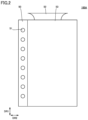
- Fig. 2 is a side view of carbon dioxide capturing apparatus 100A.
- Fig. 3 is a perspective view of an adsorber 30 included in carbon dioxide capturing apparatus 100A.
- Fig. 4 is a cross-sectional view along a line IV-IV shown in Fig. 1 .
- Fig. 5 is a diagram as seen from a direction of an arrow V shown in Fig. 1 .
- carbon dioxide capturing apparatus 100A includes a plurality of rails 10, a jig 20, and adsorber 30.
- Each rail 10 includes a first side plate 11, a second side plate 12, a plurality of shafts 13, and a plurality of rollers 14.
- First side plate 11 and second side plate 12 are disposed to face each other with a space therebetween in a second direction DR2 orthogonal to a first direction DR1.
- First direction DR1 is an upward and downward direction (vertical direction).
- Second direction DR2 is a direction orthogonal to first direction DR1.
- a third direction DR3 is a direction orthogonal to first direction DR1 and second direction DR2.
- first side plate 11 and second side plate 12 are inclined such that one end of the rail in third direction DR3 (the right end in Fig. 1 ) is located above the other end of the rail in third direction DR3 (the left end in Fig. 1 ).
- first side plate 11 and second side plate 12 are inclined such that the other end of the rail in third direction DR3 is located above one end of the rail in third direction DR3.
- the other end of rail 10B in third direction DR3 is located closer to the other side in third direction DR3 than the other end of rail 10A in third direction DR3 is.
- the one end of rail 10C in third direction DR3 is located closer to one side in third direction DR3 than the one end of rail 10B in third direction DR3 is.
- the other end of rail 10D in third direction DR3 is located closer to the other side in third direction DR3 than the other end of rail 10C in third direction DR3 is.
- Each shaft 13 is rotatably supported at one end by first side plate 11, and is rotatably supported at the other end by second side plate 12.
- the plurality of shafts 13 are arranged in rows along a direction of extension of first side plate 11 (second side plate 12).
- Each roller 14 is disposed on an outer circumferential surface of each shaft 13. Roller 14 is rotated about a central axis of shaft 13.
- Jig 20 has a plate-like shape.
- Jig 20 is disposed on rail 10. More specifically, jig 20 is disposed on the plurality of rollers 14 between first side plate 11 and second side plate 12.
- Jig 20 is rotatable on rail 10 (rollers 14).
- Jig 20 has a first surface 20a and a second surface 20b.
- First surface 20a and second surface 20b are end surfaces of jig 20 in a thickness direction.
- First surface 20a is a surface that contacts rollers 14.
- Second surface 20b is a surface opposite to first surface 20a.
- An upper end of first side plate 11 and an upper end of second side plate 12 preferably protrude beyond second surface 20b.
- Jig 20 has a circular shape, for example, as seen from a direction orthogonal to second surface 20b. Note that the planar shape of jig 20 is not limited as such.
- Adsorber 30 includes a skeleton 31 and an adsorbent 32 (not shown). Skeleton 31 has a honeycomb structure, for example.
- Adsorbent 32 is made of a material capable of adsorbing carbon dioxide.
- Adsorbent 32 supports, for example, amine, zeolite, silica gel, diatomaceous earth, alumina, activated carbon, and/or the like.
- Adsorbent 32 is attached to an inner wall surface and an outer wall surface of skeleton 31. Therefore, adsorber 30 can adsorb carbon dioxide contained in airflow regardless of the direction of the airflow toward adsorber 30.
- Adsorber 30 is disposed on jig 20. More specifically, adsorber 30 is disposed on second surface 20b.
- Adsorber 30 is moved downward together with jig 20 by the plurality of rails 10. More specifically, jig 20 and adsorber 30 move on rail 10A from one end side to the other end side of rail 10A in third direction DR3 due to the action of gravity. Jig 20 and adsorber 30 that have reached the other end side of rail 10A in third direction DR3 fall onto rail 10B.
- jig 20 and adsorber 30 move on rail 10B from the other end side to one end side of rail 10B in third direction DR3, and fall onto rail 10C. As this is repeated, jig 20 and adsorber 30 are moved downward.
- Carbon dioxide capturing apparatus 100A may further include a transfer unit 40.
- Jig 20 and adsorber 30 that have been moved downward by the plurality of rails 10 are moted upward by transfer unit 40. More specifically, jig 20 and adsorber 30 that have reached one end of lowermost rail 10 (rail 10D) in third direction DR3 are moved downward by transfer unit 40. Thus, jig 20 and adsorber 30 are returned onto uppermost rail 10 (rail 10A).
- Transfer unit 40 includes, for example, a transfer chamber 41, a wire 42, and a drive unit 43.
- Jig 20 and adsorber 30 are housed in transfer chamber 41.
- Wire 42 has one end connected to transfer chamber 41 and the other end connected to drive unit 43.
- Drive unit 43 is a motor, for example. As drive unit 43 rolls up wire 42, transfer chamber 41 is moved upward, and jig 20 and adsorber 30 are also moved upward accordingly.
- Carbon dioxide capturing apparatus 100A further includes a housing 50.
- An internal space of housing 50 includes a first space SP1 and a second space SP2.
- the plurality of rails 10 are disposed in first space SP1. Therefore, jig 20 and adsorber 30 are moved downward in first space SP1. More specifically, drive unit 43 rolls up wire 42 to move transfer chamber 41 upward in second space SP2. Transfer unit 40 moves jig 20 and adsorber 30 upward through second space SP2 in this manner.
- Housing 50 is mounted, for example, on an outdoor unit 53 of an air conditioner.
- Housing 50 has an opening in each of a front surface (a surface of housing 50 located on the opposite side of outdoor unit 53 of the air conditioner) and a rear surface (a surface of housing 50 located on the outdoor unit 53 side of the air conditioner).
- a fan (not shown) is disposed in outdoor unit 53 of the air conditioner. Rotation of the fan causes airflow to pass along second direction DR2, for example, in first space SP1. That is, the airflow is introduced into housing 50 (first space SP1) through the opening in the front surface of housing 50, and is discharged through the opening in the rear surface of housing 50.
- first space SP1 passes through outdoor unit 53 of the air conditioner and is then discharged out of outdoor unit 53 of the air conditioner through, for example, an exhaust port 52 included in outdoor unit 53 of the air conditioner.
- Housing 50 may be provided with a plurality of vent holes 51. Vent holes 51 extend through housing 50 to allow second space SP2 to communicate with an outside of housing 50.
- the airflow is also introduced into second space SP2 through vent holes 51. When vent holes 51 are formed, adsorber 30 is exposed to carbon dioxide while being transferred in second space SP2 as well.
- the airflow described above is a flow of gas containing carbon dioxide.
- first side plate 11 and the upper end of second side plate 12 protrude beyond second surface 20b. Therefore, the movement of jig 20 in a direction orthogonal to the direction of movement of jig 20 is restricted by first side plate 11 and second side plate 12. That is, jig 20 is restrained from falling from rail 10. As a result, carbon dioxide capturing apparatus 100A does not require a mesh member to cover rail 10, and air resistance during passing of the airflow in first space SP1 can be reduced.
- carbon dioxide capturing apparatus 100A When carbon dioxide capturing apparatus 100A includes transfer unit 40, jig 20 and adsorber 30 that have been moved downward by each rail 10 are returned onto uppermost rail 10 again. When carbon dioxide capturing apparatus 100A includes transfer unit 40, therefore, adsorber 30 is repeatedly exposed to the airflow, and the efficiency of capturing carbon dioxide is further improved.
- housing 50 When housing 50 is provided with vent holes 51, adsorber 30 is exposed to the airflow while being moved upward and returned onto uppermost rail 10 as well. When housing 50 is provided with vent holes 51, therefore, the efficiency of capturing carbon dioxide is further improved.
- a carbon dioxide capturing apparatus according to Embodiment 2 is described.
- the carbon dioxide capturing apparatus according to Embodiment 2 is referred to as a carbon dioxide capturing apparatus 100B. Differences from carbon dioxide capturing apparatus 100A are mainly described, and the same description is not repeated herein.
- a configuration of carbon dioxide capturing apparatus 100B is described below.
- Fig. 6 is a front view of carbon dioxide capturing apparatus 100B.
- Fig. 7 is a diagram as seen from a direction of an arrow VII shown in Fig. 6 .
- adsorber 30 is not shown.
- carbon dioxide capturing apparatus 100B includes the plurality of rails 10, jig 20, adsorber 30, transfer unit 40, and housing 50.
- the configuration of carbon dioxide capturing apparatus 100B is the same as the configuration of carbon dioxide capturing apparatus 100A.
- jig 20 is provided with a plurality of vent holes 21. Vent holes 21 extend through jig 20 along the thickness direction. In these respects, the configuration of carbon dioxide capturing apparatus 100B is different from the configuration of carbon dioxide capturing apparatus 100A.
- vent holes 21 in jig 20 are formed, and therefore, airflow can pass through vent holes 21, which leads to reduced air resistance.
- carbon dioxide contained in the airflow that has passed through vent holes 21 is also adsorbed by adsorber 30, and therefore, the efficiency of capturing carbon dioxide is further improved.
- a carbon dioxide capturing apparatus according to Embodiment 3 is described.
- the carbon dioxide capturing apparatus according to Embodiment 3 is referred to as a carbon dioxide capturing apparatus 100C. Differences from carbon dioxide capturing apparatus 100A are mainly described, and the same description is not repeated herein.
- a configuration of carbon dioxide capturing apparatus 100C is described below.
- Fig. 8 is a front view of carbon dioxide capturing apparatus 100C.
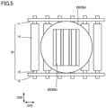
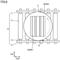
- Fig. 9 is a diagram as seen from a direction of an arrow IX shown in Fig. 8 .
- carbon dioxide capturing apparatus 100C includes the plurality of rails 10, jig 20, adsorber 30, transfer unit 40, and housing 50.
- the configuration of carbon dioxide capturing apparatus 100C is the same as the configuration of carbon dioxide capturing apparatus 100A.
- carbon dioxide capturing apparatus 100C frictional resistance between first side plate 11 and jig 20 is different from frictional resistance between second side plate 12 and jig 20.
- the configuration of carbon dioxide capturing apparatus 100C is different from the configuration of carbon dioxide capturing apparatus 100A.
- First side plate 11 is made of, for example, a material different from that of second side plate 12.
- a surface of first side plate 11 that contacts jig 20 may have a surface roughness different from that of a surface of second side plate 12 that contacts jig 20.
- Surface treatment that increases or decreases the friction with jig 20 may be applied to either the surface of first side plate 11 that contacts jig 20 or the surface of second side plate 12 that contacts jig 20. That is, the configuration in which the frictional resistance between first side plate 11 and jig 20 is different from the frictional resistance between different second side plate 12 and jig 20 is not particularly limited.
- the frictional resistance between first side plate 11 and jig 20 is different from the frictional resistance between second side plate 12 and jig 20. Therefore, an imbalance is created between a frictional force F1 acting between first side plate 11 and jig 20 (see Fig. 9 ) and a frictional force F2 acting between second side plate 12 and jig 20 (see Fig. 9 ).
- a carbon dioxide capturing apparatus according to Embodiment 4 is described.
- the carbon dioxide capturing apparatus according to Embodiment 4 is referred to as a carbon dioxide capturing apparatus 100D. Differences from carbon dioxide capturing apparatus 100A are mainly described, and the same description is not repeated herein.
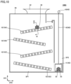
- Fig. 10 is a front view of carbon dioxide capturing apparatus 100D.
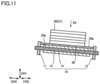
- Fig. 11 is a cross-sectional view along a line XI-XI shown in Fig. 10 .
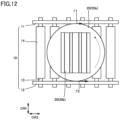
- Fig. 12 is a diagram as seen from a direction of an arrow XII shown in Fig. 11 .
- carbon dioxide capturing apparatus 100D includes the plurality of rails 10, jig 20, adsorber 30, transfer unit 40, and housing 50.
- the configuration of carbon dioxide capturing apparatus 100D is the same as the configuration of carbon dioxide capturing apparatus 100A.
- first side plate 11 and second side plate 12 face each other with a space therebetween in a fourth direction DR4.
- Fourth direction DR4 is orthogonal to third direction DR3, but is not orthogonal to first direction DR1 and second direction DR2 (is inclined with respect to first direction DR1 and second direction DR2).
- first side plate 11 faces second side plate 12 with a space therebetween, and is located above second side plate 12.
- the configuration of carbon dioxide capturing apparatus 100D is different from the configuration of carbon dioxide capturing apparatus 100A.
- first side plate 11 is located above second side plate 12, and therefore, frictional force F1 acting between first side plate 11 and jig 20 (see Fig. 12 ) is smaller than frictional force F2 acting between second side plate 12 and jig 20 (see Fig. 12 ) due to the action of gravity.
- a carbon dioxide capturing apparatus according to Embodiment 5 is described.
- the carbon dioxide capturing apparatus according to Embodiment 5 is referred to as a carbon dioxide capturing apparatus 100E. Differences from carbon dioxide capturing apparatus 100A are mainly described, and the same description is not repeated herein.
- a configuration of carbon dioxide capturing apparatus 100E is described below.
- Carbon dioxide capturing apparatus 100E includes the plurality of rails 10, jig 20, adsorber 30, transfer unit 40, and housing 50. In this respect, the configuration of carbon dioxide capturing apparatus 100E is the same as the configuration of carbon dioxide capturing apparatus 100A.
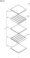
- Fig. 13 is an exploded perspective view of adsorber 30 included in carbon dioxide capturing apparatus 100E.
- Fig. 14 is a perspective view of adsorber 30 included in carbon dioxide capturing apparatus 100E.
- skeleton 31 includes a plurality of flat plate members 31a and a plurality of corrugated plate members 31b.
- Flat plate members 31a and corrugated plate members 31b are alternately stacked. Stated from a different perspective, one corrugated plate member 31b is disposed between two adjacent flat plate members 31a, and one flat plate member 31a is disposed between two adjacent corrugated plate members 31b.
- skeleton 31 is formed by alternately stacking flat plate members 31a and corrugated plate members 31b, and therefore, airflow enters skeleton 31 regardless of the direction from which the airflow impinges on adsorber 30. According to carbon dioxide capturing apparatus 100E, therefore, the efficiency of capturing carbon dioxide is further improved.
- a carbon dioxide capturing apparatus according to Embodiment 6 is described.
- the carbon dioxide capturing apparatus according to Embodiment 6 is referred to as a carbon dioxide capturing apparatus 100F. Differences from carbon dioxide capturing apparatus 100A are mainly described, and the same description is not repeated herein.
- a configuration of carbon dioxide capturing apparatus 100F is described below.
- Carbon dioxide capturing apparatus 100F includes the plurality of rails 10, jig 20, adsorber 30, transfer unit 40, and housing 50. In this respect, the configuration of carbon dioxide capturing apparatus 100F is the same as the configuration of carbon dioxide capturing apparatus 100A.
- Fig. 15 is a perspective view of adsorber 30 included in carbon dioxide capturing apparatus 100F.
- adsorber 30 in carbon dioxide capturing apparatus 100F, includes a plurality of adsorbents 32 and a container 33.
- adsorbents 32 are in the form of beads.
- Container 33 is in the form of a mesh.
- Adsorbents 32 are housed in container 33. In these respects, the configuration of carbon dioxide capturing apparatus 100F is different from the configuration of carbon dioxide capturing apparatus 100A.
- container 33 is in the form of a mesh, and therefore, airflow enters container 33 regardless of the direction from which the airflow impinges on adsorber 30, and carbon dioxide contained in the airflow is adsorbed by adsorbents 32 in the form of beads. According to carbon dioxide capturing apparatus 100F, therefore, the efficiency of capturing carbon dioxide is further improved.
- a carbon dioxide capturing apparatus according to Embodiment 7 is described.
- the carbon dioxide capturing apparatus according to Embodiment 7 is referred to as a carbon dioxide capturing apparatus 100G. Differences from carbon dioxide capturing apparatus 100A are mainly described, and the same description is not repeated herein.
- a configuration of carbon dioxide capturing apparatus 100G is described below.
- Fig. 16 is a front view of carbon dioxide capturing apparatus 100G.
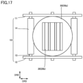
- Fig. 17 is a diagram as seen from a direction of an arrow XVII shown in Fig. 16 .
- carbon dioxide capturing apparatus 100G includes the plurality of rails 10, jig 20, adsorber 30, transfer unit 40, and housing 50.
- the configuration of carbon dioxide capturing apparatus 100G is the same as the configuration of carbon dioxide capturing apparatus 100A.
- rail 10 is configured to vibrate jig 20 and adsorber 30 while moving jig 20 and adsorber 30 downward.
- the configuration of carbon dioxide capturing apparatus 100G is different from the configuration of carbon dioxide capturing apparatus 100A.
- the distance between two adjacent shafts 13 is longer than in carbon dioxide capturing apparatus 100A.
- jig 20 and adsorber 30 are more likely to be vibrated when moving downward on rail 10.
- some of the plurality of shafts 13 may be disposed to protrude beyond the rest of the plurality of shafts 13 arranged in rows.
- vibration is more likely to be applied to jig 20 and adsorber 30 when they pass on the some of the plurality of shafts located at the protruding position.
- the configuration added to jig 20 and adsorber 30 on rail 10 is not particularly limited.
- carbon dioxide capturing apparatus 100G vibration is applied to jig 20 and adsorber 30 while jig 20 and adsorber 30 are being moved downward by each rail 10, and therefore, rotation of jig 20 and adsorber 30 on rail 10 is facilitated. According to carbon dioxide capturing apparatus 100G, therefore, the efficiency of capturing carbon dioxide is further improved.
- a carbon dioxide capturing apparatus according to Embodiment 8 is described.
- the carbon dioxide capturing apparatus according to Embodiment 8 is referred to as a carbon dioxide capturing apparatus 100H. Differences from carbon dioxide capturing apparatus 100A are mainly described, and the same description is not repeated herein.
- a configuration of carbon dioxide capturing apparatus 100H is described below.
- Fig. 18 is a front view of carbon dioxide capturing apparatus 100H.
- carbon dioxide capturing apparatus 100H includes the plurality of rails 10, jig 20, and adsorber 30. Carbon dioxide capturing apparatus 100H may further include transfer unit 40.
- the configuration of carbon dioxide capturing apparatus 100H is the same as the configuration of carbon dioxide capturing apparatus 100A.
- Carbon dioxide capturing apparatus 100H does not include housing 50.
- the configuration of carbon dioxide capturing apparatus 100H is different from the configuration of carbon dioxide capturing apparatus 100A.
- the plurality of rails 10 are mounted, for example, on outdoor unit 53 of the air conditioner.
- Carbon dioxide capturing apparatus 100H does not include housing 50, and therefore, airflow containing carbon dioxide comes into contact with adsorber 30 from all directions except for directions blocked by rails 10. According to carbon dioxide capturing apparatus 100H, therefore, the carbon dioxide can be efficiently captured.
Landscapes
- Engineering & Computer Science (AREA)
- Chemical & Material Sciences (AREA)
- Environmental & Geological Engineering (AREA)
- Analytical Chemistry (AREA)
- General Chemical & Material Sciences (AREA)
- Oil, Petroleum & Natural Gas (AREA)
- Chemical Kinetics & Catalysis (AREA)
- Health & Medical Sciences (AREA)
- Biomedical Technology (AREA)
- Treating Waste Gases (AREA)
- Separation Of Gases By Adsorption (AREA)
Abstract
Description
- The present disclosure relates to a carbon dioxide capturing apparatus.
- For example,
Japanese National Patent Publication No. 2014-516785 - PTL 1:
Japanese National Patent Publication No. 2014-516785 - In the carbon dioxide capturing apparatus described in PTL 1, the gas containing carbon dioxide impinges on the beads from only one direction. Therefore, the carbon dioxide capturing apparatus described in PTL 1 has room for improvement in efficiency of capturing carbon dioxide.
- The present disclosure has been made in view of the problem of conventional techniques as described above. More specifically, the present disclosure provides a carbon dioxide capturing apparatus capable of improving efficiency of capturing carbon dioxide.
- A carbon dioxide capturing apparatus of the present disclosure includes an adsorber, a jig, and a rail. The adsorber is disposed on the jig. The jig is rotatably disposed on the rail, and is moved downward together with the adsorber by the rail.
- According to the carbon dioxide capturing apparatus of the present disclosure, efficiency of capturing carbon dioxide can be improved.
-
-
Fig. 1 is a front view of a carbondioxide capturing apparatus 100A. -
Fig. 2 is a side view of carbondioxide capturing apparatus 100A. -
Fig. 3 is a perspective view of anadsorber 30 included in carbondioxide capturing apparatus 100A. -
Fig. 4 is a cross-sectional view along a line IV-IV shown inFig. 1 . -
Fig. 5 is a diagram as seen from a direction of an arrow V shown inFig. 1 . -
Fig. 6 is a front view of a carbondioxide capturing apparatus 100B. -
Fig. 7 is a diagram as seen from a direction of an arrow VII shown inFig. 6 . -
Fig. 8 is a front view of a carbondioxide capturing apparatus 100C. -
Fig. 9 is a diagram as seen from a direction of an arrow IX shown inFig. 8 . -
Fig. 10 is a front view of a carbondioxide capturing apparatus 100D. -
Fig. 11 is a cross-sectional view along a line XI-XI shown inFig. 10 . -
Fig. 12 is a diagram as seen from a direction of an arrow XII shown inFig. 11 . -
Fig. 13 is an exploded perspective view ofadsorber 30 included in a carbon dioxide capturing apparatus 100E. -
Fig. 14 is a perspective view ofadsorber 30 included in carbon dioxide capturing apparatus 100E. -
Fig. 15 is a perspective view ofadsorber 30 included in a carbon dioxide capturing apparatus 100F. -
Fig. 16 is a front view of a carbondioxide capturing apparatus 100G. -
Fig. 17 is a diagram as seen from a direction of an arrow XVII shown inFig. 16 . -
Fig. 18 is a front view of a carbondioxide capturing apparatus 100H. - Embodiments of the present disclosure will be described in detail with reference to the drawings. In the drawings below, the same or corresponding portions are denoted by the same reference characters and the same description will not be repeated. The embodiments described below may be applied in any appropriate combination.
- A carbon dioxide capturing apparatus according to Embodiment 1 is described. The carbon dioxide capturing apparatus according to Embodiment 1 is referred to as a carbon
dioxide capturing apparatus 100A. - A configuration of carbon
dioxide capturing apparatus 100A is described below. -
Fig. 1 is a front view of carbondioxide capturing apparatus 100A.Fig. 2 is a side view of carbondioxide capturing apparatus 100A.Fig. 3 is a perspective view of anadsorber 30 included in carbondioxide capturing apparatus 100A.Fig. 4 is a cross-sectional view along a line IV-IV shown inFig. 1 .Fig. 5 is a diagram as seen from a direction of an arrow V shown inFig. 1 . As shown inFigs. 1 to 5 , carbondioxide capturing apparatus 100A includes a plurality ofrails 10, ajig 20, and adsorber 30. - Each
rail 10 includes afirst side plate 11, asecond side plate 12, a plurality ofshafts 13, and a plurality ofrollers 14. -
First side plate 11 andsecond side plate 12 are disposed to face each other with a space therebetween in a second direction DR2 orthogonal to a first direction DR1. First direction DR1 is an upward and downward direction (vertical direction). Second direction DR2 is a direction orthogonal to first direction DR1. A third direction DR3 is a direction orthogonal to first direction DR1 and second direction DR2. - In the example shown in
Fig. 1 , the number of the plurality ofrails 10 is four. Fourrails 10 shown inFig. 1 are referred to, from top to bottom, as arail 10A, arail 10B, arail 10C, and arail 10D. In each ofrail 10A andrail 10C,first side plate 11 andsecond side plate 12 are inclined such that one end of the rail in third direction DR3 (the right end inFig. 1 ) is located above the other end of the rail in third direction DR3 (the left end inFig. 1 ). In each ofrail 10B andrail 10D,first side plate 11 andsecond side plate 12 are inclined such that the other end of the rail in third direction DR3 is located above one end of the rail in third direction DR3. - The other end of
rail 10B in third direction DR3 is located closer to the other side in third direction DR3 than the other end ofrail 10A in third direction DR3 is. The one end ofrail 10C in third direction DR3 is located closer to one side in third direction DR3 than the one end ofrail 10B in third direction DR3 is. The other end ofrail 10D in third direction DR3 is located closer to the other side in third direction DR3 than the other end ofrail 10C in third direction DR3 is. - Each
shaft 13 is rotatably supported at one end byfirst side plate 11, and is rotatably supported at the other end bysecond side plate 12. The plurality ofshafts 13 are arranged in rows along a direction of extension of first side plate 11 (second side plate 12). Eachroller 14 is disposed on an outer circumferential surface of eachshaft 13.Roller 14 is rotated about a central axis ofshaft 13. -
Jig 20 has a plate-like shape.Jig 20 is disposed onrail 10. More specifically,jig 20 is disposed on the plurality ofrollers 14 betweenfirst side plate 11 andsecond side plate 12.Jig 20 is rotatable on rail 10 (rollers 14). -
Jig 20 has afirst surface 20a and asecond surface 20b.First surface 20a andsecond surface 20b are end surfaces ofjig 20 in a thickness direction.First surface 20a is a surface thatcontacts rollers 14.Second surface 20b is a surface opposite tofirst surface 20a. An upper end offirst side plate 11 and an upper end ofsecond side plate 12 preferably protrude beyondsecond surface 20b.Jig 20 has a circular shape, for example, as seen from a direction orthogonal tosecond surface 20b. Note that the planar shape ofjig 20 is not limited as such. -
Adsorber 30 includes askeleton 31 and an adsorbent 32 (not shown).Skeleton 31 has a honeycomb structure, for example.Adsorbent 32 is made of a material capable of adsorbing carbon dioxide.Adsorbent 32 supports, for example, amine, zeolite, silica gel, diatomaceous earth, alumina, activated carbon, and/or the like.Adsorbent 32 is attached to an inner wall surface and an outer wall surface ofskeleton 31. Therefore,adsorber 30 can adsorb carbon dioxide contained in airflow regardless of the direction of the airflow towardadsorber 30.Adsorber 30 is disposed onjig 20. More specifically,adsorber 30 is disposed onsecond surface 20b. -
Adsorber 30 is moved downward together withjig 20 by the plurality ofrails 10. More specifically,jig 20 andadsorber 30 move onrail 10A from one end side to the other end side ofrail 10A in third direction DR3 due to the action of gravity.Jig 20 andadsorber 30 that have reached the other end side ofrail 10A in third direction DR3 fall ontorail 10B. - Similarly,
jig 20 andadsorber 30 move onrail 10B from the other end side to one end side ofrail 10B in third direction DR3, and fall ontorail 10C. As this is repeated,jig 20 andadsorber 30 are moved downward. - Carbon
dioxide capturing apparatus 100A may further include atransfer unit 40.Jig 20 andadsorber 30 that have been moved downward by the plurality ofrails 10 are moted upward bytransfer unit 40. More specifically,jig 20 andadsorber 30 that have reached one end of lowermost rail 10 (rail 10D) in third direction DR3 are moved downward bytransfer unit 40. Thus,jig 20 andadsorber 30 are returned onto uppermost rail 10 (rail 10A). -
Transfer unit 40 includes, for example, atransfer chamber 41, awire 42, and adrive unit 43.Jig 20 andadsorber 30 are housed intransfer chamber 41.Wire 42 has one end connected to transferchamber 41 and the other end connected to driveunit 43.Drive unit 43 is a motor, for example. Asdrive unit 43 rolls upwire 42,transfer chamber 41 is moved upward, andjig 20 andadsorber 30 are also moved upward accordingly. - Carbon
dioxide capturing apparatus 100A further includes ahousing 50. An internal space ofhousing 50 includes a first space SP1 and a second space SP2. The plurality ofrails 10 are disposed in first space SP1. Therefore,jig 20 andadsorber 30 are moved downward in first space SP1. More specifically,drive unit 43 rolls upwire 42 to movetransfer chamber 41 upward in second space SP2.Transfer unit 40 movesjig 20 andadsorber 30 upward through second space SP2 in this manner. -
Housing 50 is mounted, for example, on anoutdoor unit 53 of an air conditioner.Housing 50 has an opening in each of a front surface (a surface ofhousing 50 located on the opposite side ofoutdoor unit 53 of the air conditioner) and a rear surface (a surface ofhousing 50 located on theoutdoor unit 53 side of the air conditioner). A fan (not shown) is disposed inoutdoor unit 53 of the air conditioner. Rotation of the fan causes airflow to pass along second direction DR2, for example, in first space SP1. That is, the airflow is introduced into housing 50 (first space SP1) through the opening in the front surface ofhousing 50, and is discharged through the opening in the rear surface ofhousing 50. The airflow that has passed through first space SP1 passes throughoutdoor unit 53 of the air conditioner and is then discharged out ofoutdoor unit 53 of the air conditioner through, for example, anexhaust port 52 included inoutdoor unit 53 of the air conditioner. Note that the direction of passing of the airflow in first space SP1 is not limited as such.Housing 50 may be provided with a plurality of vent holes 51. Vent holes 51 extend throughhousing 50 to allow second space SP2 to communicate with an outside ofhousing 50. The airflow is also introduced into second space SP2 through vent holes 51. When vent holes 51 are formed,adsorber 30 is exposed to carbon dioxide while being transferred in second space SP2 as well. The airflow described above is a flow of gas containing carbon dioxide. - Effects of carbon
dioxide capturing apparatus 100A are described below. - There is airflow in first space SP1 as described above, and therefore, the airflow impinges on
adsorber 30 whileadsorber 30 is being moved downward by eachrail 10, andadsorber 30 adsorbs carbon dioxide in the airflow. If the airflow impinges onadsorber 30 from only one direction, carbon dioxide is less likely to be adsorbed in a portion ofadsorber 30 that is located downstream of the airflow, resulting in low efficiency of capturing carbon dioxide. In carbondioxide capturing apparatus 100A, on the other hand,jig 20 is rotatably disposed onrail 10, and therefore, different portions ofadsorber 30 face upstream of the airflow whileadsorber 30 is being moved downward. According to carbondioxide capturing apparatus 100A, therefore, the efficiency of capturing carbon dioxide is improved. - In carbon
dioxide capturing apparatus 100A, the upper end offirst side plate 11 and the upper end ofsecond side plate 12 protrude beyondsecond surface 20b. Therefore, the movement ofjig 20 in a direction orthogonal to the direction of movement ofjig 20 is restricted byfirst side plate 11 andsecond side plate 12. That is,jig 20 is restrained from falling fromrail 10. As a result, carbondioxide capturing apparatus 100A does not require a mesh member to coverrail 10, and air resistance during passing of the airflow in first space SP1 can be reduced. - When carbon
dioxide capturing apparatus 100A includestransfer unit 40,jig 20 andadsorber 30 that have been moved downward by eachrail 10 are returned ontouppermost rail 10 again. When carbondioxide capturing apparatus 100A includestransfer unit 40, therefore,adsorber 30 is repeatedly exposed to the airflow, and the efficiency of capturing carbon dioxide is further improved. Whenhousing 50 is provided with vent holes 51,adsorber 30 is exposed to the airflow while being moved upward and returned ontouppermost rail 10 as well. Whenhousing 50 is provided with vent holes 51, therefore, the efficiency of capturing carbon dioxide is further improved. - A carbon dioxide capturing apparatus according to Embodiment 2 is described. The carbon dioxide capturing apparatus according to Embodiment 2 is referred to as a carbon
dioxide capturing apparatus 100B. Differences from carbondioxide capturing apparatus 100A are mainly described, and the same description is not repeated herein. - A configuration of carbon
dioxide capturing apparatus 100B is described below. -
Fig. 6 is a front view of carbondioxide capturing apparatus 100B.Fig. 7 is a diagram as seen from a direction of an arrow VII shown inFig. 6 . InFig. 7 ,adsorber 30 is not shown. As shown inFigs. 6 and7 , carbondioxide capturing apparatus 100B includes the plurality ofrails 10,jig 20,adsorber 30,transfer unit 40, andhousing 50. In this respect, the configuration of carbondioxide capturing apparatus 100B is the same as the configuration of carbondioxide capturing apparatus 100A. - In carbon
dioxide capturing apparatus 100B,jig 20 is provided with a plurality of vent holes 21. Vent holes 21 extend throughjig 20 along the thickness direction. In these respects, the configuration of carbondioxide capturing apparatus 100B is different from the configuration of carbondioxide capturing apparatus 100A. - Effects of carbon
dioxide capturing apparatus 100B are described below. - In carbon
dioxide capturing apparatus 100B, vent holes 21 injig 20 are formed, and therefore, airflow can pass through vent holes 21, which leads to reduced air resistance. In addition, carbon dioxide contained in the airflow that has passed through vent holes 21 is also adsorbed byadsorber 30, and therefore, the efficiency of capturing carbon dioxide is further improved. - A carbon dioxide capturing apparatus according to Embodiment 3 is described. The carbon dioxide capturing apparatus according to Embodiment 3 is referred to as a carbon
dioxide capturing apparatus 100C. Differences from carbondioxide capturing apparatus 100A are mainly described, and the same description is not repeated herein. - A configuration of carbon
dioxide capturing apparatus 100C is described below. -
Fig. 8 is a front view of carbondioxide capturing apparatus 100C.Fig. 9 is a diagram as seen from a direction of an arrow IX shown inFig. 8 . As shown inFigs. 8 and9 , carbondioxide capturing apparatus 100C includes the plurality ofrails 10,jig 20,adsorber 30,transfer unit 40, andhousing 50. In this respect, the configuration of carbondioxide capturing apparatus 100C is the same as the configuration of carbondioxide capturing apparatus 100A. - In carbon
dioxide capturing apparatus 100C, frictional resistance betweenfirst side plate 11 andjig 20 is different from frictional resistance betweensecond side plate 12 andjig 20. In this respect, the configuration of carbondioxide capturing apparatus 100C is different from the configuration of carbondioxide capturing apparatus 100A. -
First side plate 11 is made of, for example, a material different from that ofsecond side plate 12. A surface offirst side plate 11 thatcontacts jig 20 may have a surface roughness different from that of a surface ofsecond side plate 12 thatcontacts jig 20. Surface treatment that increases or decreases the friction withjig 20 may be applied to either the surface offirst side plate 11 thatcontacts jig 20 or the surface ofsecond side plate 12 thatcontacts jig 20. That is, the configuration in which the frictional resistance betweenfirst side plate 11 andjig 20 is different from the frictional resistance between differentsecond side plate 12 andjig 20 is not particularly limited. - Effects of carbon
dioxide capturing apparatus 100C are described below. - In carbon
dioxide capturing apparatus 100C, the frictional resistance betweenfirst side plate 11 andjig 20 is different from the frictional resistance betweensecond side plate 12 andjig 20. Therefore, an imbalance is created between a frictional force F1 acting betweenfirst side plate 11 and jig 20 (seeFig. 9 ) and a frictional force F2 acting betweensecond side plate 12 and jig 20 (seeFig. 9 ). - This imbalance between the frictional forces facilitates rotation of
jig 20 on rail 10 (see a dotted arrow inFig. 9 ). As a result, in carbondioxide capturing apparatus 100C, various portions ofadsorber 30 are more likely to face upstream of the airflow passing through first space SP1, and the efficiency of capturing carbon dioxide is further improved. - A carbon dioxide capturing apparatus according to Embodiment 4 is described. The carbon dioxide capturing apparatus according to Embodiment 4 is referred to as a carbon
dioxide capturing apparatus 100D. Differences from carbondioxide capturing apparatus 100A are mainly described, and the same description is not repeated herein. - A configuration of carbon
dioxide capturing apparatus 100D is described below. -
Fig. 10 is a front view of carbondioxide capturing apparatus 100D.Fig. 11 is a cross-sectional view along a line XI-XI shown inFig. 10 .Fig. 12 is a diagram as seen from a direction of an arrow XII shown inFig. 11 . As shown inFigs. 10 to 12 , carbondioxide capturing apparatus 100D includes the plurality ofrails 10,jig 20,adsorber 30,transfer unit 40, andhousing 50. In this respect, the configuration of carbondioxide capturing apparatus 100D is the same as the configuration of carbondioxide capturing apparatus 100A. - In carbon
dioxide capturing apparatus 100D,first side plate 11 andsecond side plate 12 face each other with a space therebetween in a fourth direction DR4. Fourth direction DR4 is orthogonal to third direction DR3, but is not orthogonal to first direction DR1 and second direction DR2 (is inclined with respect to first direction DR1 and second direction DR2). Stated from a different perspective,first side plate 11 facessecond side plate 12 with a space therebetween, and is located abovesecond side plate 12. In these respects, the configuration of carbondioxide capturing apparatus 100D is different from the configuration of carbondioxide capturing apparatus 100A. - Effects of carbon
dioxide capturing apparatus 100D are described below. - In carbon
dioxide capturing apparatus 100D,first side plate 11 is located abovesecond side plate 12, and therefore, frictional force F1 acting betweenfirst side plate 11 and jig 20 (seeFig. 12 ) is smaller than frictional force F2 acting betweensecond side plate 12 and jig 20 (seeFig. 12 ) due to the action of gravity. - This imbalance between the frictional forces facilitates rotation of
jig 20 on rail 10 (see a dotted arrow inFig. 12 ). As a result, in carbondioxide capturing apparatus 100D, various portions ofadsorber 30 are more likely to face upstream of the airflow passing through first space SP1, and the efficiency of capturing carbon dioxide is further improved. - A carbon dioxide capturing apparatus according to Embodiment 5 is described. The carbon dioxide capturing apparatus according to Embodiment 5 is referred to as a carbon dioxide capturing apparatus 100E. Differences from carbon
dioxide capturing apparatus 100A are mainly described, and the same description is not repeated herein. - A configuration of carbon dioxide capturing apparatus 100E is described below.
- Carbon dioxide capturing apparatus 100E includes the plurality of
rails 10,jig 20,adsorber 30,transfer unit 40, andhousing 50. In this respect, the configuration of carbon dioxide capturing apparatus 100E is the same as the configuration of carbondioxide capturing apparatus 100A. -
Fig. 13 is an exploded perspective view ofadsorber 30 included in carbon dioxide capturing apparatus 100E.Fig. 14 is a perspective view ofadsorber 30 included in carbon dioxide capturing apparatus 100E. As shown inFigs. 13 and14 , in carbon dioxide capturing apparatus 100E,skeleton 31 includes a plurality offlat plate members 31a and a plurality ofcorrugated plate members 31b.Flat plate members 31a andcorrugated plate members 31b are alternately stacked. Stated from a different perspective, onecorrugated plate member 31b is disposed between two adjacentflat plate members 31a, and oneflat plate member 31a is disposed between two adjacentcorrugated plate members 31b. - Each corrugated plate member 3 1b has a plurality of grooves 31ba. Grooves 31ba extend linearly. The plurality of grooves 31ba are arranged in a direction orthogonal to a direction of extension of grooves 31ba. A direction of extension of grooves 31ba in one of two adjacent
corrugated plate members 31b is orthogonal to a direction of extension of grooves 31ba in the other of the two adjacentcorrugated plate members 31b. Although not shown,adsorbent 32 is attached to a surface ofskeleton 31. - Effects of carbon dioxide capturing apparatus 100E are described below.
- In carbon dioxide capturing apparatus 100E,
skeleton 31 is formed by alternately stackingflat plate members 31a andcorrugated plate members 31b, and therefore, airflow entersskeleton 31 regardless of the direction from which the airflow impinges onadsorber 30. According to carbon dioxide capturing apparatus 100E, therefore, the efficiency of capturing carbon dioxide is further improved. - A carbon dioxide capturing apparatus according to Embodiment 6 is described. The carbon dioxide capturing apparatus according to Embodiment 6 is referred to as a carbon dioxide capturing apparatus 100F. Differences from carbon
dioxide capturing apparatus 100A are mainly described, and the same description is not repeated herein. - A configuration of carbon dioxide capturing apparatus 100F is described below.
- Carbon dioxide capturing apparatus 100F includes the plurality of
rails 10,jig 20,adsorber 30,transfer unit 40, andhousing 50. In this respect, the configuration of carbon dioxide capturing apparatus 100F is the same as the configuration of carbondioxide capturing apparatus 100A. -
Fig. 15 is a perspective view ofadsorber 30 included in carbon dioxide capturing apparatus 100F. As shown inFig. 15 , in carbon dioxide capturing apparatus 100F,adsorber 30 includes a plurality ofadsorbents 32 and acontainer 33. In carbon dioxide capturing apparatus 100F,adsorbents 32 are in the form of beads.Container 33 is in the form of a mesh.Adsorbents 32 are housed incontainer 33. In these respects, the configuration of carbon dioxide capturing apparatus 100F is different from the configuration of carbondioxide capturing apparatus 100A. - Effects of carbon dioxide capturing apparatus 100F are described below.
- In carbon dioxide capturing apparatus 100F,
container 33 is in the form of a mesh, and therefore, airflow enterscontainer 33 regardless of the direction from which the airflow impinges onadsorber 30, and carbon dioxide contained in the airflow is adsorbed byadsorbents 32 in the form of beads. According to carbon dioxide capturing apparatus 100F, therefore, the efficiency of capturing carbon dioxide is further improved. - A carbon dioxide capturing apparatus according to Embodiment 7 is described. The carbon dioxide capturing apparatus according to Embodiment 7 is referred to as a carbon
dioxide capturing apparatus 100G. Differences from carbondioxide capturing apparatus 100A are mainly described, and the same description is not repeated herein. - A configuration of carbon
dioxide capturing apparatus 100G is described below. -
Fig. 16 is a front view of carbondioxide capturing apparatus 100G.Fig. 17 is a diagram as seen from a direction of an arrow XVII shown inFig. 16 . As shown inFigs. 16 and17 , carbondioxide capturing apparatus 100G includes the plurality ofrails 10,jig 20,adsorber 30,transfer unit 40, andhousing 50. In this respect, the configuration of carbondioxide capturing apparatus 100G is the same as the configuration of carbondioxide capturing apparatus 100A. - In carbon
dioxide capturing apparatus 100G,rail 10 is configured to vibratejig 20 andadsorber 30 while movingjig 20 andadsorber 30 downward. In this respect, the configuration of carbondioxide capturing apparatus 100G is different from the configuration of carbondioxide capturing apparatus 100A. - In carbon
dioxide capturing apparatus 100G, the distance between twoadjacent shafts 13 is longer than in carbondioxide capturing apparatus 100A. Thus, in carbondioxide capturing apparatus 100G,jig 20 andadsorber 30 are more likely to be vibrated when moving downward onrail 10. In carbondioxide capturing apparatus 100G, some of the plurality ofshafts 13 may be disposed to protrude beyond the rest of the plurality ofshafts 13 arranged in rows. Thus, vibration is more likely to be applied tojig 20 andadsorber 30 when they pass on the some of the plurality of shafts located at the protruding position. In other words, in carbondioxide capturing apparatus 100G, the configuration added tojig 20 andadsorber 30 onrail 10 is not particularly limited. - Effects of carbon
dioxide capturing apparatus 100G are described below. - In carbon
dioxide capturing apparatus 100G, vibration is applied tojig 20 andadsorber 30 whilejig 20 andadsorber 30 are being moved downward by eachrail 10, and therefore, rotation ofjig 20 andadsorber 30 onrail 10 is facilitated. According to carbondioxide capturing apparatus 100G, therefore, the efficiency of capturing carbon dioxide is further improved. - A carbon dioxide capturing apparatus according to Embodiment 8 is described. The carbon dioxide capturing apparatus according to Embodiment 8 is referred to as a carbon
dioxide capturing apparatus 100H. Differences from carbondioxide capturing apparatus 100A are mainly described, and the same description is not repeated herein. - A configuration of carbon
dioxide capturing apparatus 100H is described below. -
Fig. 18 is a front view of carbondioxide capturing apparatus 100H. As shown inFig. 18 , carbondioxide capturing apparatus 100H includes the plurality ofrails 10,jig 20, andadsorber 30. Carbondioxide capturing apparatus 100H may further includetransfer unit 40. In this respect, the configuration of carbondioxide capturing apparatus 100H is the same as the configuration of carbondioxide capturing apparatus 100A. Carbondioxide capturing apparatus 100H does not includehousing 50. In this respect, the configuration of carbondioxide capturing apparatus 100H is different from the configuration of carbondioxide capturing apparatus 100A. In carbondioxide capturing apparatus 100H, the plurality ofrails 10 are mounted, for example, onoutdoor unit 53 of the air conditioner. - Effects of carbon
dioxide capturing apparatus 100H are described below. - Carbon
dioxide capturing apparatus 100H does not includehousing 50, and therefore, airflow containing carbon dioxide comes into contact withadsorber 30 from all directions except for directions blocked byrails 10. According to carbondioxide capturing apparatus 100H, therefore, the carbon dioxide can be efficiently captured. - It should be understood that the embodiments disclosed herein are illustrative and non-restrictive in every respect. The basic scope of the present disclosure is defined by the terms of the claims, rather than the embodiments described above, and is intended to include any modifications within the meaning and scope equivalent to the terms of the claims.
- 10, 10A, 10B, 10C, 10D rail; 11 first side plate; 12 second side plate; 13 shaft; 14 roller; 20 jig; 20a first surface; 20b second surface; 21 vent hole; 30 adsorber; 31 skeleton; 31a flat plate member; 31b corrugated plate member; 31ba groove; 32 adsorbent; 33 container; 40 transfer unit; 41 transfer chamber; 42 wire; 43 drive unit; 50 housing; 51 vent hole; 52 exhaust port; 53 outdoor unit of air conditioner; 100A carbon dioxide capturing apparatus; 100B, 100C, 100D, 100E, 100F, 100G, 100H carbon dioxide capturing apparatus; DR1 first direction; DR2 second direction; DR3 third direction; DR4 fourth direction; F1, F2 frictional force; SP1 first space; SP2 second space.
Claims (10)
- A carbon dioxide capturing apparatus comprising:an adsorber;a jig; anda rail, whereinthe adsorber is disposed on the jig, andthe jig is rotatably disposed on the rail, and is moved downward together with the adsorber by the rail.
- The carbon dioxide capturing apparatus according to claim 1,
wherein
the jig is provided with a first vent hole extending through the jig. - The carbon dioxide capturing apparatus according to claim 1 or 2, further comprising:a housing; anda transfer unit, whereinan internal space of the housing includes a first space and a second space,the housing is provided with a second vent hole that allows the second space to communicate with an outside of the housing, andafter being moved downward in the first space by the rail, the jig and the adsorber are moved upward through the second space and returned onto the rail by the transfer unit.
- The carbon dioxide capturing apparatus according to any one of claims 1 to 3, whereinthe rail includes a first side plate, a second side plate, a plurality of shafts, and a plurality of rollers,the first side plate and the second side plate are disposed to face each other with a space therebetween in a direction intersecting an upward and downward direction,each of the plurality of shafts is rotatably supported at one end by the first side plate, and is rotatably supported at the other end by the second side plate,the plurality of shafts are arranged in rows along a direction of extension of the first side plate and the second side plate,each of the plurality of rollers is disposed on an outer circumferential surface of each of the plurality of shafts, andthe jig is disposed on the plurality of rollers between the first side plate and the second side plate.
- The carbon dioxide capturing apparatus according to claim 4,
whereinthe jig has a first surface facing the plurality of rollers, and a second surface which is opposite to the first surface and on which the adsorber is disposed, andan upper end of the first side plate and an upper end of the second side plate are located at a position protruding beyond the second surface. - The carbon dioxide capturing apparatus according to claim 5,
whereinthe jig has a circular shape as seen from a direction orthogonal to the second surface, andfrictional resistance between the first side plate and the jig is different from frictional resistance between the second side plate and the jig. - The carbon dioxide capturing apparatus according to claim 5 or 6,
wherein
the first side plate and the second side plate are disposed to face each other with a space therebetween in a direction inclined with respect to an upward and downward direction. - The carbon dioxide capturing apparatus according to any one of claims 1 to 7, whereinthe adsorber includes a skeleton formed of a plurality of flat plate members and a plurality of corrugated plate members,each of the plurality of corrugated plate members has a plurality of linearly extending grooves,one of the plurality of corrugated plate members is disposed between two adjacent ones of the plurality of flat plate members, anda direction of extension of the plurality grooves in one of two adjacent ones of the plurality of corrugated plate members is orthogonal to a direction of extension of the plurality grooves in the other of the two adjacent ones of the plurality of corrugated plate members.
- The carbon dioxide capturing apparatus according to any one of claims 1 to 7, whereinthe adsorber includes an adsorption container, and a plurality of beads which are disposed in the adsorption container and which are capable of adsorbing carbon dioxide, andthe adsorption container is in the form of a mesh.
- The carbon dioxide capturing apparatus according to any one of claims 1 to 9, wherein
the rail is configured to move the jig and the adsorber downward while vibrating the jig and the adsorber.
Applications Claiming Priority (2)
| Application Number | Priority Date | Filing Date | Title |
|---|---|---|---|
| PCT/JP2022/027821 WO2024013973A1 (en) | 2022-07-15 | 2022-07-15 | Carbon dioxide recovery device |
| PCT/JP2023/025755 WO2024014486A1 (en) | 2022-07-15 | 2023-07-12 | Carbon dioxide recovery device |
Publications (2)
| Publication Number | Publication Date |
|---|---|
| EP4556100A1 true EP4556100A1 (en) | 2025-05-21 |
| EP4556100A4 EP4556100A4 (en) | 2025-11-12 |
Family
ID=89536340
Family Applications (1)
| Application Number | Title | Priority Date | Filing Date |
|---|---|---|---|
| EP23839658.4A Pending EP4556100A4 (en) | 2022-07-15 | 2023-07-12 | Carbon dioxide recovery device |
Country Status (4)
| Country | Link |
|---|---|
| EP (1) | EP4556100A4 (en) |
| JP (1) | JP7422964B1 (en) |
| CN (1) | CN119562848A (en) |
| WO (2) | WO2024013973A1 (en) |
Families Citing this family (1)
| Publication number | Priority date | Publication date | Assignee | Title |
|---|---|---|---|---|
| JP7829811B1 (en) * | 2024-04-24 | 2026-03-13 | 三菱電機株式会社 | Gas recovery device |
Family Cites Families (7)
| Publication number | Priority date | Publication date | Assignee | Title |
|---|---|---|---|---|
| JPS4848382A (en) * | 1971-10-18 | 1973-07-09 | ||
| JPS6321312Y2 (en) * | 1986-03-20 | 1988-06-13 | ||
| JP2001137646A (en) * | 1999-11-15 | 2001-05-22 | Kureha Techno Enji Kk | Device and method for adsorption treating waste gas |
| JP4317304B2 (en) * | 1999-11-15 | 2009-08-19 | 株式会社クレハエンジニアリング | Apparatus and method for multistage adsorption treatment of exhaust gas |
| US9073005B2 (en) | 2011-06-09 | 2015-07-07 | Sri International | Falling microbead counter-flow process for separating gas mixtures |
| US9539540B2 (en) * | 2013-07-08 | 2017-01-10 | Exxonmobil Research And Engineering Company | Rotary moving bed for CO2 separation and use of same |
| CA3186480A1 (en) * | 2020-06-26 | 2021-12-30 | Socpra Sciences Et Genie S.E.C. | System and method for continuous gas adsorbate capture using adsorption/regeneration cycle |
-
2022
- 2022-07-15 WO PCT/JP2022/027821 patent/WO2024013973A1/en not_active Ceased
-
2023
- 2023-07-12 WO PCT/JP2023/025755 patent/WO2024014486A1/en not_active Ceased
- 2023-07-12 EP EP23839658.4A patent/EP4556100A4/en active Pending
- 2023-07-12 CN CN202380051670.3A patent/CN119562848A/en active Pending
- 2023-07-12 JP JP2023566620A patent/JP7422964B1/en active Active
Also Published As
| Publication number | Publication date |
|---|---|
| JP7422964B1 (en) | 2024-01-26 |
| EP4556100A4 (en) | 2025-11-12 |
| WO2024014486A1 (en) | 2024-01-18 |
| WO2024013973A1 (en) | 2024-01-18 |
| CN119562848A (en) | 2025-03-04 |
| JPWO2024014486A1 (en) | 2024-01-18 |
Similar Documents
| Publication | Publication Date | Title |
|---|---|---|
| EP4556100A1 (en) | Carbon dioxide recovery device | |
| US20240390845A1 (en) | Polymeric amine sorbents for gas separation using a moisture swing regeneration step | |
| EP2596844A1 (en) | Grease Filter | |
| JP2002320817A (en) | Dehumidifying device and dehumidifying method | |
| KR20220088164A (en) | An air purification device with carbon dioxide emission function and a method for purifying an air | |
| JP4490155B2 (en) | Nitrogen oxide removal equipment | |
| US6280504B1 (en) | Hygroscopic monolith having a channel therethrough for modifying a gas therein by adsorption or desorption, and processes therefor | |
| JP5443230B2 (en) | Fan filter unit | |
| JPWO2024014486A5 (en) | ||
| KR101134541B1 (en) | High-Performance Labyrinth Type Air Treatment Apparatus | |
| US3538688A (en) | Lower filter assembly | |
| CN1997437A (en) | Chemical filtration unit incorporating air transportation device | |
| CN223337078U (en) | Carbon dioxide adsorption component and device for removing carbon dioxide | |
| JPS5828513B2 (en) | Jiyuusou Reikyakutou | |
| US20250334284A1 (en) | Rotor for an air conditioning system with a plurality of sorbent sections | |
| TW202224752A (en) | Filter mesh frame, filter mesh structure and method for using the same | |
| TWI912942B (en) | Adsorption unit having spacer pieces | |
| JPH0884929A (en) | Adsorbent | |
| JP7829811B1 (en) | Gas recovery device | |
| KR20220002395A (en) | adsorption treatment device | |
| JP2023145014A (en) | Carbon dioxide treatment device | |
| CN121371796A (en) | Smoke and exhaust gas treatment device and method based on antistatic terrace construction | |
| JP2002191926A (en) | Removal device | |
| JP2015114007A (en) | Humidity control device | |
| KR20190016246A (en) | Air cleaning panel and wall including the same |
Legal Events
| Date | Code | Title | Description |
|---|---|---|---|
| STAA | Information on the status of an ep patent application or granted ep patent |
Free format text: STATUS: THE INTERNATIONAL PUBLICATION HAS BEEN MADE |
|
| PUAI | Public reference made under article 153(3) epc to a published international application that has entered the european phase |
Free format text: ORIGINAL CODE: 0009012 |
|
| STAA | Information on the status of an ep patent application or granted ep patent |
Free format text: STATUS: REQUEST FOR EXAMINATION WAS MADE |
|
| 17P | Request for examination filed |
Effective date: 20241211 |
|
| AK | Designated contracting states |
Kind code of ref document: A1 Designated state(s): AL AT BE BG CH CY CZ DE DK EE ES FI FR GB GR HR HU IE IS IT LI LT LU LV MC ME MK MT NL NO PL PT RO RS SE SI SK SM TR |
|
| DAV | Request for validation of the european patent (deleted) | ||
| DAX | Request for extension of the european patent (deleted) | ||
| A4 | Supplementary search report drawn up and despatched |
Effective date: 20251014 |
|
| RIC1 | Information provided on ipc code assigned before grant |
Ipc: B01D 53/08 20060101AFI20251008BHEP Ipc: B01D 53/62 20060101ALI20251008BHEP |