EP4556038A2 - Autoinjector - Google Patents
Autoinjector Download PDFInfo
- Publication number
- EP4556038A2 EP4556038A2 EP25158096.5A EP25158096A EP4556038A2 EP 4556038 A2 EP4556038 A2 EP 4556038A2 EP 25158096 A EP25158096 A EP 25158096A EP 4556038 A2 EP4556038 A2 EP 4556038A2
- Authority
- EP
- European Patent Office
- Prior art keywords
- autoinjector
- case
- door
- syringe
- exemplary embodiment
- Prior art date
- Legal status (The legal status is an assumption and is not a legal conclusion. Google has not performed a legal analysis and makes no representation as to the accuracy of the status listed.)
- Pending
Links
Images






Classifications
-
- A—HUMAN NECESSITIES
- A61—MEDICAL OR VETERINARY SCIENCE; HYGIENE
- A61M—DEVICES FOR INTRODUCING MEDIA INTO, OR ONTO, THE BODY; DEVICES FOR TRANSDUCING BODY MEDIA OR FOR TAKING MEDIA FROM THE BODY; DEVICES FOR PRODUCING OR ENDING SLEEP OR STUPOR
- A61M5/00—Devices for bringing media into the body in a subcutaneous, intra-vascular or intramuscular way; Accessories therefor, e.g. filling or cleaning devices, arm rests
- A61M5/178—Syringes
- A61M5/20—Automatic syringes, e.g. with automatically actuated piston rod, with automatic needle injection, filling automatically
- A61M5/2033—Spring-loaded one-shot injectors with or without automatic needle insertion
-
- A—HUMAN NECESSITIES
- A61—MEDICAL OR VETERINARY SCIENCE; HYGIENE
- A61M—DEVICES FOR INTRODUCING MEDIA INTO, OR ONTO, THE BODY; DEVICES FOR TRANSDUCING BODY MEDIA OR FOR TAKING MEDIA FROM THE BODY; DEVICES FOR PRODUCING OR ENDING SLEEP OR STUPOR
- A61M5/00—Devices for bringing media into the body in a subcutaneous, intra-vascular or intramuscular way; Accessories therefor, e.g. filling or cleaning devices, arm rests
- A61M5/178—Syringes
- A61M5/31—Details
- A61M5/3129—Syringe barrels
-
- A—HUMAN NECESSITIES
- A61—MEDICAL OR VETERINARY SCIENCE; HYGIENE
- A61M—DEVICES FOR INTRODUCING MEDIA INTO, OR ONTO, THE BODY; DEVICES FOR TRANSDUCING BODY MEDIA OR FOR TAKING MEDIA FROM THE BODY; DEVICES FOR PRODUCING OR ENDING SLEEP OR STUPOR
- A61M5/00—Devices for bringing media into the body in a subcutaneous, intra-vascular or intramuscular way; Accessories therefor, e.g. filling or cleaning devices, arm rests
- A61M5/178—Syringes
- A61M5/31—Details
- A61M5/32—Needles; Details of needles pertaining to their connection with syringe or hub; Accessories for bringing the needle into, or holding the needle on, the body; Devices for protection of needles
- A61M5/3205—Apparatus for removing or disposing of used needles or syringes, e.g. containers; Means for protection against accidental injuries from used needles
- A61M5/321—Means for protection against accidental injuries by used needles
- A61M5/3243—Means for protection against accidental injuries by used needles being axially-extensible, e.g. protective sleeves coaxially slidable on the syringe barrel
- A61M5/3245—Constructional features thereof, e.g. to improve manipulation or functioning
-
- A—HUMAN NECESSITIES
- A61—MEDICAL OR VETERINARY SCIENCE; HYGIENE
- A61M—DEVICES FOR INTRODUCING MEDIA INTO, OR ONTO, THE BODY; DEVICES FOR TRANSDUCING BODY MEDIA OR FOR TAKING MEDIA FROM THE BODY; DEVICES FOR PRODUCING OR ENDING SLEEP OR STUPOR
- A61M5/00—Devices for bringing media into the body in a subcutaneous, intra-vascular or intramuscular way; Accessories therefor, e.g. filling or cleaning devices, arm rests
- A61M5/178—Syringes
- A61M5/20—Automatic syringes, e.g. with automatically actuated piston rod, with automatic needle injection, filling automatically
- A61M2005/2006—Having specific accessories
- A61M2005/202—Having specific accessories cocking means, e.g. to bias the main drive spring of an injector
-
- A—HUMAN NECESSITIES
- A61—MEDICAL OR VETERINARY SCIENCE; HYGIENE
- A61M—DEVICES FOR INTRODUCING MEDIA INTO, OR ONTO, THE BODY; DEVICES FOR TRANSDUCING BODY MEDIA OR FOR TAKING MEDIA FROM THE BODY; DEVICES FOR PRODUCING OR ENDING SLEEP OR STUPOR
- A61M5/00—Devices for bringing media into the body in a subcutaneous, intra-vascular or intramuscular way; Accessories therefor, e.g. filling or cleaning devices, arm rests
- A61M5/178—Syringes
- A61M5/20—Automatic syringes, e.g. with automatically actuated piston rod, with automatic needle injection, filling automatically
- A61M2005/2073—Automatic syringes, e.g. with automatically actuated piston rod, with automatic needle injection, filling automatically preventing premature release, e.g. by making use of a safety lock
- A61M2005/208—Release is possible only when device is pushed against the skin, e.g. using a trigger which is blocked or inactive when the device is not pushed against the skin
-
- A—HUMAN NECESSITIES
- A61—MEDICAL OR VETERINARY SCIENCE; HYGIENE
- A61M—DEVICES FOR INTRODUCING MEDIA INTO, OR ONTO, THE BODY; DEVICES FOR TRANSDUCING BODY MEDIA OR FOR TAKING MEDIA FROM THE BODY; DEVICES FOR PRODUCING OR ENDING SLEEP OR STUPOR
- A61M5/00—Devices for bringing media into the body in a subcutaneous, intra-vascular or intramuscular way; Accessories therefor, e.g. filling or cleaning devices, arm rests
- A61M5/178—Syringes
- A61M5/31—Details
- A61M5/3129—Syringe barrels
- A61M2005/314—Flat shaped barrel forms, e.g. credit card shaped
-
- A—HUMAN NECESSITIES
- A61—MEDICAL OR VETERINARY SCIENCE; HYGIENE
- A61M—DEVICES FOR INTRODUCING MEDIA INTO, OR ONTO, THE BODY; DEVICES FOR TRANSDUCING BODY MEDIA OR FOR TAKING MEDIA FROM THE BODY; DEVICES FOR PRODUCING OR ENDING SLEEP OR STUPOR
- A61M5/00—Devices for bringing media into the body in a subcutaneous, intra-vascular or intramuscular way; Accessories therefor, e.g. filling or cleaning devices, arm rests
- A61M5/178—Syringes
- A61M5/31—Details
- A61M5/32—Needles; Details of needles pertaining to their connection with syringe or hub; Accessories for bringing the needle into, or holding the needle on, the body; Devices for protection of needles
- A61M5/3205—Apparatus for removing or disposing of used needles or syringes, e.g. containers; Means for protection against accidental injuries from used needles
- A61M5/321—Means for protection against accidental injuries by used needles
- A61M5/3243—Means for protection against accidental injuries by used needles being axially-extensible, e.g. protective sleeves coaxially slidable on the syringe barrel
- A61M5/3245—Constructional features thereof, e.g. to improve manipulation or functioning
- A61M2005/3247—Means to impede repositioning of protection sleeve from needle covering to needle uncovering position
-
- A—HUMAN NECESSITIES
- A61—MEDICAL OR VETERINARY SCIENCE; HYGIENE
- A61M—DEVICES FOR INTRODUCING MEDIA INTO, OR ONTO, THE BODY; DEVICES FOR TRANSDUCING BODY MEDIA OR FOR TAKING MEDIA FROM THE BODY; DEVICES FOR PRODUCING OR ENDING SLEEP OR STUPOR
- A61M2205/00—General characteristics of the apparatus
- A61M2205/33—Controlling, regulating or measuring
- A61M2205/3368—Temperature
-
- A—HUMAN NECESSITIES
- A61—MEDICAL OR VETERINARY SCIENCE; HYGIENE
- A61M—DEVICES FOR INTRODUCING MEDIA INTO, OR ONTO, THE BODY; DEVICES FOR TRANSDUCING BODY MEDIA OR FOR TAKING MEDIA FROM THE BODY; DEVICES FOR PRODUCING OR ENDING SLEEP OR STUPOR
- A61M2205/00—General characteristics of the apparatus
- A61M2205/58—Means for facilitating use, e.g. by people with impaired vision
- A61M2205/581—Means for facilitating use, e.g. by people with impaired vision by audible feedback
-
- A—HUMAN NECESSITIES
- A61—MEDICAL OR VETERINARY SCIENCE; HYGIENE
- A61M—DEVICES FOR INTRODUCING MEDIA INTO, OR ONTO, THE BODY; DEVICES FOR TRANSDUCING BODY MEDIA OR FOR TAKING MEDIA FROM THE BODY; DEVICES FOR PRODUCING OR ENDING SLEEP OR STUPOR
- A61M2205/00—General characteristics of the apparatus
- A61M2205/58—Means for facilitating use, e.g. by people with impaired vision
- A61M2205/582—Means for facilitating use, e.g. by people with impaired vision by tactile feedback
-
- A—HUMAN NECESSITIES
- A61—MEDICAL OR VETERINARY SCIENCE; HYGIENE
- A61M—DEVICES FOR INTRODUCING MEDIA INTO, OR ONTO, THE BODY; DEVICES FOR TRANSDUCING BODY MEDIA OR FOR TAKING MEDIA FROM THE BODY; DEVICES FOR PRODUCING OR ENDING SLEEP OR STUPOR
- A61M2205/00—General characteristics of the apparatus
- A61M2205/58—Means for facilitating use, e.g. by people with impaired vision
- A61M2205/583—Means for facilitating use, e.g. by people with impaired vision by visual feedback
-
- A—HUMAN NECESSITIES
- A61—MEDICAL OR VETERINARY SCIENCE; HYGIENE
- A61M—DEVICES FOR INTRODUCING MEDIA INTO, OR ONTO, THE BODY; DEVICES FOR TRANSDUCING BODY MEDIA OR FOR TAKING MEDIA FROM THE BODY; DEVICES FOR PRODUCING OR ENDING SLEEP OR STUPOR
- A61M2205/00—General characteristics of the apparatus
- A61M2205/58—Means for facilitating use, e.g. by people with impaired vision
- A61M2205/586—Ergonomic details therefor, e.g. specific ergonomics for left or right-handed users
-
- A—HUMAN NECESSITIES
- A61—MEDICAL OR VETERINARY SCIENCE; HYGIENE
- A61M—DEVICES FOR INTRODUCING MEDIA INTO, OR ONTO, THE BODY; DEVICES FOR TRANSDUCING BODY MEDIA OR FOR TAKING MEDIA FROM THE BODY; DEVICES FOR PRODUCING OR ENDING SLEEP OR STUPOR
- A61M2205/00—General characteristics of the apparatus
- A61M2205/60—General characteristics of the apparatus with identification means
-
- A—HUMAN NECESSITIES
- A61—MEDICAL OR VETERINARY SCIENCE; HYGIENE
- A61M—DEVICES FOR INTRODUCING MEDIA INTO, OR ONTO, THE BODY; DEVICES FOR TRANSDUCING BODY MEDIA OR FOR TAKING MEDIA FROM THE BODY; DEVICES FOR PRODUCING OR ENDING SLEEP OR STUPOR
- A61M2205/00—General characteristics of the apparatus
- A61M2205/60—General characteristics of the apparatus with identification means
- A61M2205/6009—General characteristics of the apparatus with identification means for matching patient with his treatment, e.g. to improve transfusion security
-
- A—HUMAN NECESSITIES
- A61—MEDICAL OR VETERINARY SCIENCE; HYGIENE
- A61M—DEVICES FOR INTRODUCING MEDIA INTO, OR ONTO, THE BODY; DEVICES FOR TRANSDUCING BODY MEDIA OR FOR TAKING MEDIA FROM THE BODY; DEVICES FOR PRODUCING OR ENDING SLEEP OR STUPOR
- A61M5/00—Devices for bringing media into the body in a subcutaneous, intra-vascular or intramuscular way; Accessories therefor, e.g. filling or cleaning devices, arm rests
- A61M5/178—Syringes
- A61M5/20—Automatic syringes, e.g. with automatically actuated piston rod, with automatic needle injection, filling automatically
- A61M5/206—Automatic syringes, e.g. with automatically actuated piston rod, with automatic needle injection, filling automatically with automatic needle insertion
-
- A—HUMAN NECESSITIES
- A61—MEDICAL OR VETERINARY SCIENCE; HYGIENE
- A61M—DEVICES FOR INTRODUCING MEDIA INTO, OR ONTO, THE BODY; DEVICES FOR TRANSDUCING BODY MEDIA OR FOR TAKING MEDIA FROM THE BODY; DEVICES FOR PRODUCING OR ENDING SLEEP OR STUPOR
- A61M5/00—Devices for bringing media into the body in a subcutaneous, intra-vascular or intramuscular way; Accessories therefor, e.g. filling or cleaning devices, arm rests
- A61M5/178—Syringes
- A61M5/31—Details
- A61M5/32—Needles; Details of needles pertaining to their connection with syringe or hub; Accessories for bringing the needle into, or holding the needle on, the body; Devices for protection of needles
- A61M5/3202—Devices for protection of the needle before use, e.g. caps
-
- A—HUMAN NECESSITIES
- A61—MEDICAL OR VETERINARY SCIENCE; HYGIENE
- A61M—DEVICES FOR INTRODUCING MEDIA INTO, OR ONTO, THE BODY; DEVICES FOR TRANSDUCING BODY MEDIA OR FOR TAKING MEDIA FROM THE BODY; DEVICES FOR PRODUCING OR ENDING SLEEP OR STUPOR
- A61M5/00—Devices for bringing media into the body in a subcutaneous, intra-vascular or intramuscular way; Accessories therefor, e.g. filling or cleaning devices, arm rests
- A61M5/178—Syringes
- A61M5/31—Details
- A61M5/32—Needles; Details of needles pertaining to their connection with syringe or hub; Accessories for bringing the needle into, or holding the needle on, the body; Devices for protection of needles
- A61M5/3202—Devices for protection of the needle before use, e.g. caps
- A61M5/3204—Needle cap removers, i.e. devices to dislodge protection cover from needle or needle hub, e.g. deshielding devices
-
- A—HUMAN NECESSITIES
- A61—MEDICAL OR VETERINARY SCIENCE; HYGIENE
- A61M—DEVICES FOR INTRODUCING MEDIA INTO, OR ONTO, THE BODY; DEVICES FOR TRANSDUCING BODY MEDIA OR FOR TAKING MEDIA FROM THE BODY; DEVICES FOR PRODUCING OR ENDING SLEEP OR STUPOR
- A61M5/00—Devices for bringing media into the body in a subcutaneous, intra-vascular or intramuscular way; Accessories therefor, e.g. filling or cleaning devices, arm rests
- A61M5/178—Syringes
- A61M5/31—Details
- A61M5/32—Needles; Details of needles pertaining to their connection with syringe or hub; Accessories for bringing the needle into, or holding the needle on, the body; Devices for protection of needles
- A61M5/3205—Apparatus for removing or disposing of used needles or syringes, e.g. containers; Means for protection against accidental injuries from used needles
- A61M5/321—Means for protection against accidental injuries by used needles
- A61M5/3243—Means for protection against accidental injuries by used needles being axially-extensible, e.g. protective sleeves coaxially slidable on the syringe barrel
- A61M5/326—Fully automatic sleeve extension, i.e. in which triggering of the sleeve does not require a deliberate action by the user
-
- A—HUMAN NECESSITIES
- A61—MEDICAL OR VETERINARY SCIENCE; HYGIENE
- A61M—DEVICES FOR INTRODUCING MEDIA INTO, OR ONTO, THE BODY; DEVICES FOR TRANSDUCING BODY MEDIA OR FOR TAKING MEDIA FROM THE BODY; DEVICES FOR PRODUCING OR ENDING SLEEP OR STUPOR
- A61M5/00—Devices for bringing media into the body in a subcutaneous, intra-vascular or intramuscular way; Accessories therefor, e.g. filling or cleaning devices, arm rests
- A61M5/46—Devices for bringing media into the body in a subcutaneous, intra-vascular or intramuscular way; Accessories therefor, e.g. filling or cleaning devices, arm rests having means for controlling depth of insertion
Definitions
- the invention relates to an autoinjector for administering a medicament.
- Administering an injection is a process which presents a number of risks and challenges for users and healthcare professionals, both mental and physical.
- Injection devices typically fall into two categories - manual devices and autoinjectors.
- manual force is required to drive a medicament through a needle. This is typically done by some form of button / plunger that has to be continuously pressed during the injection.
- button / plunger that has to be continuously pressed during the injection.
- There are numerous disadvantages associated with this approach For example, if the button / plunger is released prematurely, the injection will stop and may not deliver an intended dose. Further, the force required to push the button / plunger may be too high (e.g., if the user is elderly or a child). And, aligning the injection device, administering the injection and keeping the injection device still during the injection may require dexterity which some patients (e.g., elderly patients, children, arthritic patients, etc.) may not have.
- electro-mechanical or fully electronic autoinjectors may not be as robust as fully mechanical autoinjectors.
- electro-mechanical or fully electronic autoinjectors may include batteries which require replacement and may be more difficult or impossible to fix if a component breaks.
- an autoinjector comprises a case, a door hingedly coupled to the case and having an open position and a closed position, a plunger slidably disposed in the case, and at least one drive spring applying a biasing force on the plunger relative to the case.
- the door is operably coupled to the plunger, and rotation of the door from the closed position to the open position moves the plunger from a distal position in the case to a proximal position in the case and compresses the at least one drive spring.
- an autoinjector according to the present invention further comprises a trigger button disposed on the case and operably coupled to the plunger.
- an autoinjector according to the present invention further comprises an interlock sleeve slidably disposed in the case and having an extended position and a retracted position relative to the case.
- the interlock sleeve includes at least one interlock beam extending axially in the case.
- an autoinjector according to the present invention further comprises at least one resilient button locking beam disposed in the case and adapted to engage the at least one interlock beam. The interlock beam causes the button locking beam to deflect when the interlock sleeve is in the retracted position.
- an autoinjector further comprises at least one trigger button beam operably coupled to the trigger button, and the at least one trigger button beam abuts the at least one button locking beam when the interlock sleeve is in the extended position.
- the at least one trigger button beam causes the at least one tongue to disengage the ratchet face when the trigger button is actuated and the interlock sleeve is in the retracted position.
- the plunger includes a transverse beam, a piston rod extending from the transverse beam, and at least one leg extending from the transverse beam and parallel to the piston rod.
- the at least one leg includes a distal foot adapted to support the at least one drive spring.
- the at least one leg includes a ratchet face having a plurality of teeth.
- an autoinjector according to the present invention further comprises at least one resilient tongue disposed in the case and having a hook adapted to engage a tooth on the ratchet face.
- an autoinjector further comprises at least one lever hingedly coupled to the door, and at least one roller rotatably coupled to the lever.
- the roller is disposed in a track formed in the case.
- an autoinjector further comprises a retraction collar adapted to engage a needle boot on a syringe.
- a retraction collar adapted to engage a needle boot on a syringe.
- drug or “medicament”, as used herein, means a pharmaceutical formulation containing at least one pharmaceutically active compound
- Insulin analogues are for example Gly(A21), Arg(B31), Arg(B32) human insulin; Lys(B3), Glu(B29) human insulin; Lys(B28), Pro(B29) human insulin; Asp(B28) human insulin; human insulin, wherein proline in position B28 is replaced by Asp, Lys, Leu, Val or Ala and wherein in position B29 Lys may be replaced by Pro; Ala(B26) human insulin; Des(B28-B30) human insulin; Des(B27) human insulin and Des(B30) human insulin.
- Insulin derivates are for example B29-N-myristoyl-des(B30) human insulin; B29-N-palmitoyl-des(B30) human insulin; B29-N-myristoyl human insulin; B29-N-palmitoyl human insulin; B28-N-myristoyl LysB28ProB29 human insulin; B28-N-palmitoyl-LysB28ProB29 human insulin; B30-N-myristoyl-ThrB29LysB30 human insulin; B30-N-palmitoyl- ThrB29LysB30 human insulin; B29-N-(N-palmitoyl-Y-glutamyl)-des(B30) human insulin; B29-N-(N-lithocholyl-Y-glutamyl)-des(B30) human insulin; B29-N-( ⁇ -carboxyheptadecanoyl)-des(B30) human insulin and B29-N-( ⁇ -carbox
- Exendin-4 for example means Exendin-4(1-39), a peptide of the sequence H-His-Gly-Glu-Gly-Thr-Phe-Thr-Ser-Asp-Leu-Ser-Lys-Gln-Met-Glu-Glu-Glu-Ala-Val-Arg-Leu-Phe-Ile-Glu-Trp-Leu-Lys-Asn-Gly-Gly-Pro-Ser-Ser-Gly-Ala-Pro-Pro-Pro-Ser-NH2.
- Exendin-4 derivatives are for example selected from the following list of compounds:
- Hormones are for example hypophysis hormones or hypothalamus hormones or regulatory active peptides and their antagonists as listed in Rote Liste, ed. 2008, Chapter 50 , such as Gonadotropine (Follitropin, Lutropin, Choriongonadotropin, Menotropin), Somatropine (Somatropin), Desmopressin, Terlipressin, Gonadorelin, Triptorelin, Leuprorelin, Buserelin, Nafarelin, Goserelin.
- Gonadotropine Follitropin, Lutropin, Choriongonadotropin, Menotropin
- Somatropine Somatropin
- Desmopressin Terlipressin
- Gonadorelin Triptorelin
- Leuprorelin Buserelin
- Nafarelin Goserelin.
- a polysaccharide is for example a glucosaminoglycane, a hyaluronic acid, a heparin, a low molecular weight heparin or an ultra low molecular weight heparin or a derivative thereof, or a sulphated, e.g. a poly-sulphated form of the above-mentioned polysaccharides, and/or a pharmaceutically acceptable salt thereof.
- An example of a pharmaceutically acceptable salt of a poly-sulphated low molecular weight heparin is enoxaparin sodium.
- Antibodies are globular plasma proteins ( ⁇ 150 kDa) that are also known as immunoglobulins which share a basic structure. As they have sugar chains added to amino acid residues, they are glycoproteins.
- the basic functional unit of each antibody is an immunoglobulin (Ig) monomer (containing only one Ig unit); secreted antibodies can also be dimeric with two Ig units as with IgA, tetrameric with four Ig units like teleost fish IgM, or pentameric with five Ig units, like mammalian IgM.
- Ig immunoglobulin
- the Ig monomer is a "Y"-shaped molecule that consists of four polypeptide chains; two identical heavy chains and two identical light chains connected by disulfide bonds between cysteine residues. Each heavy chain is about 440 amino acids long; each light chain is about 220 amino acids long. Heavy and light chains each contain intrachain disulfide bonds which stabilize their folding. Each chain is composed of structural domains called Ig domains. These domains contain about 70-110 amino acids and are classified into different categories (for example, variable or V, and constant or C) according to their size and function. They have a characteristic immunoglobulin fold in which two ⁇ sheets create a "sandwich" shape, held together by interactions between conserved cysteines and other charged amino acids.
- Ig heavy chain There are five types of mammalian Ig heavy chain denoted by ⁇ , ⁇ , ⁇ , ⁇ , and ⁇ .
- the type of heavy chain present defines the isotype of antibody; these chains are found in IgA, IgD, IgE, IgG, and IgM antibodies, respectively.
- Distinct heavy chains differ in size and composition; ⁇ and ⁇ contain approximately 450 amino acids and ⁇ approximately 500 amino acids, while ⁇ and ⁇ have approximately 550 amino acids.
- Each heavy chain has two regions, the constant region (C H ) and the variable region (V H ).
- the constant region is essentially identical in all antibodies of the same isotype, but differs in antibodies of different isotypes.
- Heavy chains ⁇ , ⁇ and ⁇ have a constant region composed of three tandem Ig domains, and a hinge region for added flexibility; heavy chains ⁇ and ⁇ have a constant region composed of four immunoglobulin domains.
- the variable region of the heavy chain differs in antibodies produced by different B cells, but is the same for all antibodies produced by a single B cell or B cell clone.
- the variable region of each heavy chain is approximately 110 amino acids long and is composed of a single Ig domain.
- a light chain has two successive domains: one constant domain (CL) and one variable domain (VL).
- CL constant domain
- VL variable domain
- the approximate length of a light chain is 211 to 217 amino acids.
- Each antibody contains two light chains that are always identical; only one type of light chain, ⁇ or ⁇ , is present per antibody in mammals.
- variable (V) regions are responsible for binding to the antigen, i.e. for its antigen specificity.
- VL variable light
- VH variable heavy chain
- CDRs Complementarity Determining Regions
- an "antibody fragment” contains at least one antigen binding fragment as defined above, and exhibits essentially the same function and specificity as the complete antibody of which the fragment is derived from.
- Limited proteolytic digestion with papain cleaves the Ig prototype into three fragments. Two identical amino terminal fragments, each containing one entire L chain and about half an H chain, are the antigen binding fragments (Fab).
- the Fc contains carbohydrates, complement-binding, and FcR-binding sites.
- F(ab')2 is divalent for antigen binding.
- the disulfide bond of F(ab')2 may be cleaved in order to obtain Fab'.
- the variable regions of the heavy and light chains can be fused together to form a single chain variable fragment (scFv).
- Pharmaceutically acceptable salts are for example acid addition salts and basic salts.
- Acid addition salts are e.g. HCl or HBr salts.
- Basic salts are e.g. salts having a cation selected from alkali or alkaline, e.g. Na+, or K+, or Ca2+, or an ammonium ion N+(R1)(R2)(R3)(R4), wherein R1 to R4 independently of each other mean: hydrogen, an optionally substituted C1-C6-alkyl group, an optionally substituted C2-C6-alkenyl group, an optionally substituted C6-C10-aryl group, or an optionally substituted C6-C10-heteroaryl group.
- solvates are for example hydrates.
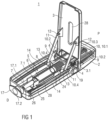
- Figure 1 is a perspective semitransparent view of an exemplary embodiment of an autoinjector 1 according to the present invention.
- the autoinjector 1 comprises a case 2 designed to be held by a patient, health-care provider or other user during an injection.
- the case 2 may have a generally elongate, rectangular shape and may include one or more ergonomic features (e.g., finger grooves for gripping) and/or textured surfaces or skins for preventing a user's hand from slipping while using the autoinjector 1.
- the case 2 includes a door 3 which is configurable in an open position or a closed position.
- the door 3 provides access to a syringe carrier in the case 2 that is adapted to hold a syringe 6 or a cartridge containing a medicament.
- the door 3 may be locked.
- the door 3 may be formed on a side of the case 2 and rotate about a transverse hinge between the open and closed positions.
- the door 3 may be formed on any side or face of the case 2 and may rotate, slide or translate relative to the case 2 to open and close.
- a door spring may be arranged in the case 2 to bias the door 3 to the open position.
- a door latch may be formed on the case 2 and/or the door 3 to maintain the door 3 in the closed position.
- the door latch may be rotated or deflected to engage/disengage the case 2 and/or the door 3 to allow the door 3 to open and close.
- At least one drive spring 9 is disposed in the case 2.
- two drive springs 9 are compression springs disposed in parallel in the case 2.
- Those of skill in the art will understand that other exemplary embodiments may utilize a single drive spring, and one or more tension or torsion drive springs.
- the drive springs 9 apply a biasing force on a plunger 10.
- the plunger 10 comprises a piston rod 10.1 projecting distally from a transverse beam 10.3 and two legs 10.2 projecting distally from opposing lateral portions of the transverse beam 10.3 and parallel to the piston rod 10.1.
- each drive spring 9 is positioned between a proximal end of the case 2 and a distal foot 10.4 of each leg 10.2.
- At least one lever 11 is hingedly coupled to the door 3 at a first end via a pivot 12 and engages a roller 13 at a second end.
- the roller 13 may be disposed in an axial track 14 which is formed in the case 2, and the roller 13 may be adapted to engage the distal foot 10.4 of the leg 10.2 of the plunger 10 when the door 3 is moved from the closed position to the open position.
- the second end of the lever 11 may engage the track 14 and be axially moveable relative thereto.
- a projection or abutment surface may be coupled to the second end of the lever 11 and adapted to engage the distal foot 10.4 of the leg 10.2.
- the door 3 and the levers 11 may be utilized as a reset mechanism.
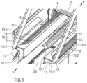
- FIG. 2 shows an exemplary embodiment of an autoinjector 1 according to the present invention.
- the door 3 is in the opened position, and a roller 13 is abutting the distal foot 10.4 of each leg 10.2.
- each leg 10.2 includes a ratchet face 10.5 having teeth that are adapted to engage a hook 15.1 on a resilient tongue 15.
- the tongue 15 may be an elongate member formed in the case 2 which is fixed at one end and deflectable at an opposite end having the hook 15.1, and the tongue 15 may be biased toward the leg 10.2.
- the teeth on the ratchet face 10.5 may engage the hook 15.1 to prevent the plunger 10 from moving in the distal direction during a reset operation and/or while moving the door 3 from the closed position to the open position.
- the teeth on the ratchet face 10.5 and the hook 15.1 may have corresponding ramped engagement surfaces to reduce a force required to open the door 3.
- Figure 2 also shows an exemplary embodiment of guide pins 10.6 which may be formed on a proximal end of the case 2 and project in a distal direction through holes in the transverse beam 10.3.
- the guide pins 10.6 may provide support and alignment for the drive springs 9.
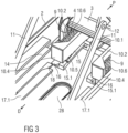
- Figure 3 shows an exemplary embodiment of an autoinjector 1 according to the present invention.
- the plunger 10 has been fully translated in the proximal direction P
- the drive springs 9 have been compressed
- the hooks 15.1 have engaged a distal-most tooth on each ratchet face 10.5
- the door 3 is being closed.
- the autoinjector 1 includes a trigger button (not visible in the figures) arranged on the case 2.
- the trigger button serves for starting an injection process when actuated.
- the trigger button may be a push button, a switch, a dial (e.g., to vary needle penetration depth), etc.
- the trigger button may be arranged on a proximal end of the case 2 or a side of the case.
- the trigger button may be replaced by a push-actuated device, which is actuated when the autoinjector 1 is placed on the injection site.
- a spring biases the trigger button relative to the case 2.
- the autoinjector 1 includes an interlock sleeve 17 slidably disposed in the case 2.
- the interlock sleeve 17 includes a distal end which protrudes from an aperture formed in a distal end of the case 2.
- the distal end of the interlock sleeve 17 includes an aperture 17.2 for allowing a needle to pass through during needle insertion into the injection site.
- the distal end of the interlock sleeve 17 may further include an expanded contact face to support proper alignment of the autoinjector 1 on the injection site and provide additional stability during the injection.
- the interlock sleeve 17 may be biased by a spring in an extended position, which position is shown in the exemplary embodiment in figure 1 .
- interlock sleeve 17 may be pushed in the proximal direction into a retracted position against the biasing force of the spring.
- Figures 3 and 4 show an exemplary embodiment of the autoinjector 1 according to the present invention in which the trigger button is operably coupled to the interlock sleeve 17.
- the trigger button when the interlock sleeve 17 is in the extended position, the trigger button may be locked and prevented from actuation.
- the trigger button When the interlock sleeve 17 is in the retracted position, the trigger button may be unlocked and actuatable.
- two interlock beams 17.1 extend in the proximal direction from the distal end of the interlock sleeve 17.
- the interlock beams 17.1 are maintained on an inside of the case 2, and may include abutment surfaces which engage a distal end of the case 2 when the interlock sleeve 17 is in the extended position.
- Proximal ends of the interlock beams 17.1 include ramped surfaces which engage corresponding ramped surfaces of resilient button locking beams 18 disposed in the case 2. When the interlock sleeve 17 moves from the extended position to the retracted position, the proximal ends of the interlock beams 17.1 cause the button locking beams 18 to deflect.
- the button locking beams 18 are adapted to engage distal ends of trigger button beams 16, which are operably coupled to the trigger button, and prevent the trigger button beams 16 from moving in the distal direction.
- the trigger button beams 16 may move in the distal direction.
- the distal ends of the trigger button beams 16 are in ramped engagement with the resilient tongues 15.
- the trigger button is actuatable when the interlock sleeve 17 is in the retracted position. Otherwise, the trigger button is prevented from actuation, because the button locking beams 18 abut the trigger button beams 16, as shown in figures 3 and 4 .
- a door lock 19 may be disposed on the case 2.
- the door lock 19 may be a button, a switch or other component which maintains the door 3 in the closed position.
- the door lock 19 has a pin 19.1 which projects into the interior of the case 2.
- the door lock 19 may have a proximal position in which the pin 19.1 is disengages from a door hook 3.1 (shown in figure 1 ) and a distal position in which the pin 19.1 engages the door hook 3.1.
- the door lock 19 may be biased (e.g., by a spring) in the distal position, and when the door is moved from the open position to the closed position, a ramped portion of the door hook 3.1 may move the pin 19.1 and the door lock 19 into the proximal position until the door 3 is closed, and then the door lock 19 may return (under the biasing force) to the distal position so that the pin 19.1 engages the door hook 3.1 and locks the door 3.
- FIGS 5-7 show an exemplary embodiment of a syringe 6 for use with the autoinjector 1 according to the present invention.
- the syringe 6 includes a body 20 containing a medicament and a case 21 telescopically coupled to the body 20.
- the case 21 may include an attachment (e.g., hooks, snaps, etc.) which engage a finger flange 20.1 on a proximal end of the body 20.
- a needle shield 23 is telescopically coupled to the case 21 and is biased toward the distal direction relative to the case 21 by a spring 24.
- the needle shield 23 is retained in its retracted state (shown in Figure 16 ) by a pivoted clip 21.1 on the case 21 which in a non-deflected position engages a recess in the needle shield 23 and in a deflected position disengages the recess in the needle shield 23.
- a needle 22 is disposed at a distal end of the body 20.
- a needle boot 7 is, as shown in Figure 5 , arranged on the needle 22, prior to use.
- Figure 6 shows the syringe 6 with the needle boot 7 removed and the needle shield 23 in a retracted position, with the needle 22 exposed.
- Figure 7 shows the syringe 6 with the needle shield 23 in an extended position, covering a distal tip of the needle 22.
- the needle shield 23 may be locked in its extended position, as shown in Figure 17 , by a resilient beam 23.2 which is released and abuts the case 21 once the shield 23 is in its fully extended position.
- a data storage device 27 may be disposed on the syringe 6 and include data, such as a type and volume of the medicament, filling and/or expiration date of the medicament, temperature of the medicament (e.g., if there is a temperature sensor on or near the syringe 4), a manufacturer of the medicament and/or the autoinjector 1, patient data (e.g., name, physician, dosing regiment, etc.), a used/unused indicator, etc.
- the data storage device 27 may interface with a wired or wireless communication device for transmitting the data to a computing device.
- the computing device may be used for tracking use/attributes of the syringe 6, e.g., for compliance and/or quality control purposes.
- the autoinjector 1 includes a retraction collar 25 distally supporting the syringe 6 and biased against the case 2 in the proximal direction P by a retraction spring 26 so that the syringe 6 is biased towards a retracted position in which the needle 22 is covered within the case 2.
- the retraction collar 25 is utilized for removing the needle boot 7 prior to an injection.
- the retraction collar 25 includes a flange which is adapted to engage the needle boot 7.
- the flange may engage a proximal surface on an annular boot collar 7.1 on the needle boot 7.
- the levers 11 and/or the rollers 13 may operably engage the retraction collar 25 to advance the retraction collar 25 in the distal direction, against the force of the retraction spring 26.
- the needle boot 7 may then be at least partially disengage from the needle 22 and at least partially exposed through the aperture 17.2 in the distal end of the interlock sleeve 17.
- the syringe assembly 6 is held in place via interference between a boss 21.2 on the syringe case 21 and a ramped boss 2.1 on the case 2.
- the force to overcome the interference is higher than the forces generated as the door 3 is closed; however it is lower than the drive forces during device firing.
- the case 2 and/or the door 3 may include a viewing window 28 for allowing inspection of the syringe 6 and its contents and state.
- a distal end of the piston rod 10.1 may comprise resilient elements which may be inwardly deflected so as to reduce an external diameter of the distal end of the piston rod 10.1.
- the external diameter of the distal end of the piston rod 10.1 is slightly greater than an internal diameter of the proximal end of the syringe body 20.
- the resilient elements may be rounded off or ramped so that they may be inwardly deflected when pushing on the proximal end of the syringe body 20 and when a counteracting force of the syringe body 20 exceeds a predetermined value.
- the proximal end of the syringe body 20 may exhibit an internal circumferential collar slightly reducing the internal diameter of the syringe body 20 and providing an additional detent which has to be overcome by the distal end of the piston rod 10.1 before it can enter the syringe body 20. If the piston rod 10.1 is advanced in the distal direction, it contacts the collar. As long as the syringe body 20 can move in the distal direction the counteracting force from the syringe body 20 may be too low to deflect the resilient elements. Hence, the piston rod 10.1 advances the syringe body 20 and the whole syringe for extending the needle 22 from the case 2 without pushing on the stopper 8.
- Figure 8 shows an exemplary embodiment of an autoinjector 1 according to the present invention prior to use.
- the door 3 is locked in the closed position, because the door hook 3.1 engages the pin 19.1 on the door lock 19.
- the interlock sleeve 17 is in the extended position.
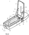
- Figure 9 shows an exemplary embodiment of an autoinjector 1 according to the present invention prior to use, with the door 3 in the open position.
- the pin 19.1 disengages the door hook 3.1, and a spring may rotate the door 3 from the closed position.
- the spring may be forceful enough to move the door 3 to the open position, or the spring may rotate the door 3 from the closed position and a user may be required to rotate the door 3 to the full open position, as shown in Figure 9 .
- the rollers 13 move proximally along the respective tracks 14, pushing the legs 10.2 and, thus, the plunger 10 proximally, which compresses the drive springs 9.
- the distal-most teeth on the ratchet face 10.5 of the legs 10.1 engage the hook 15.1 on the resilient tongue 15.
- the teeth on the ratchet face 10.5 engaging the hook 15.1 prevent the plunger 10 from moving distally when the door 3 is being opened.
- Figure 10 shows an exemplary embodiment of an autoinjector 1 according to the present invention prior to use with a syringe 6.
- the syringe 6 is placed in a syringe carrier which is slidably disposed in the case 2 or in a channel in the case 2 which allows the syringe 6 to translate relative to the case 2.
- the syringe 6 may be aligned such that the annular boot collar 7.1 on the needle boot 7 engages the flange on the retraction collar 25.
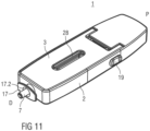
- Figure 11 shows an exemplary embodiment of an autoinjector 1 according to the present invention with an unused syringe 6 in the case 2 and the door 3 in the closed position.
- the levers 11 and/or the rollers 13 may operably engage the retraction collar 25 to advance the retraction collar 25 in the distal direction, against the force of the retraction spring 26.
- the needle boot 7 may be at least partially disengaged from the needle 22 and at least partially exposed through the aperture 17.2 in the distal end of the interlock sleeve 17.
- the user may then grip the needle boot 7 and pull it off the needle 22, which may remain covered by the interlock sleeve 17.
- the trigger button of the autoinjector 1 is locked, because the trigger button beams 16 abut the interlock beams 17.1.
- Figure 12 shows an exemplary embodiment of an autoinjector 1 according to the present invention during use, when the autoinjector 1 has been pressed against an injection site.
- the interlock sleeve 17 translates in the proximal direction relative to the case 2.
- the interlock beams 17.2 engage the button locking beams 18, causing the button locking beams 18 to deflect. Because the button locking beams 18 are deflected, they no longer prevent the trigger button beams 16 from moving distally relative to the case 2, and thus the trigger button is operable.
- Figure 13 shows an exemplary embodiment of an autoinjector 1 according to the present invention during use.
- the trigger button When the trigger button is pressed, the trigger button beams 16 move distally relative to the case 2, and deflect the tongues 15.
- the hook 15.1 disengages the ratchet faces 10.5 of the legs 10.2, and the plunger 10, under the force of the drive springs 9, moves distally relative to the case 2.
- the plunger 10 As the plunger 10 moves distally relative to the case 2, it first engages the syringe 6 (or the syringe carrier) and pushes the syringe 6 distally relative to the case 2 for insertion of the needle 22 into the injection site.
- the needle 22 passes through the aperture 17.2 in the interlock sleeve 17, as shown in figure 13 .
- the syringe 6 or the syringe carrier
- the remaining force in the drive springs 10 causes the plunger 10 to engage and push the stopper 8 in the syringe 6, dispensing the medicament in the syringe 6.
- the plunger 10 may engage a second stop in the case 2 to limit its movement relative to the syringe 6 after the syringe 6 has engaged the first stop.
- the autoinjector 1 may include one or more feedback mechanisms which provide visual, audible and/or tactile feedback regarding progress of the injection. For example, when the hook 15.1 disengages the ratchet face 10.5, a clicking sound may be generated to notify the user that the injection has begun. Visual feedback may be provided, for example, through the window(s) 28 in the case 2.
- Figure 14 shows an exemplary embodiment of an autoinjector 1 according to the present invention after use.
- the interlock sleeve 17 returns to the extended state under the force of the spring, the retraction spring 26 exerts force on the syringe 6 (or the syringe carrier) to withdraw the needle 22 from the injection site, and, because the trigger button has been released, the ratchet faces 10.5 engage the legs 10.2 to maintain the plunger 10 in position relative to the case 2.
- the ratchet faces 10.5 may engage the hooks 15.1 to prevent the plunger 10 from further advancing the stopper 8.
- the needle shield 23 is advanced to and locked in the extended position by the needle shield spring 24, as shown in Figure 15 .
- the needle 22 is covered by the locked needle shield 23 and does not present risk of needle stick injury.
Landscapes
- Health & Medical Sciences (AREA)
- Engineering & Computer Science (AREA)
- Heart & Thoracic Surgery (AREA)
- Vascular Medicine (AREA)
- Anesthesiology (AREA)
- Biomedical Technology (AREA)
- Hematology (AREA)
- Life Sciences & Earth Sciences (AREA)
- Animal Behavior & Ethology (AREA)
- General Health & Medical Sciences (AREA)
- Public Health (AREA)
- Veterinary Medicine (AREA)
- Environmental & Geological Engineering (AREA)
- Infusion, Injection, And Reservoir Apparatuses (AREA)
- Medicines Containing Antibodies Or Antigens For Use As Internal Diagnostic Agents (AREA)
Abstract
Description
- The invention relates to an autoinjector for administering a medicament.
- Administering an injection is a process which presents a number of risks and challenges for users and healthcare professionals, both mental and physical. Injection devices typically fall into two categories - manual devices and autoinjectors. In a conventional manual device, manual force is required to drive a medicament through a needle. This is typically done by some form of button / plunger that has to be continuously pressed during the injection. There are numerous disadvantages associated with this approach. For example, if the button / plunger is released prematurely, the injection will stop and may not deliver an intended dose. Further, the force required to push the button / plunger may be too high (e.g., if the user is elderly or a child). And, aligning the injection device, administering the injection and keeping the injection device still during the injection may require dexterity which some patients (e.g., elderly patients, children, arthritic patients, etc.) may not have.
- Autoinjector devices aim to make self-injection easier for patients. A conventional autoinjector may provide the force for administering the injection by a spring, and trigger button or other mechanism may be used to activate the injection. Autoinjectors may be single-use or reusable devices.
- Conventional electro-mechanical or fully electronic autoinjectors may not be as robust as fully mechanical autoinjectors. For example, electro-mechanical or fully electronic autoinjectors may include batteries which require replacement and may be more difficult or impossible to fix if a component breaks.
- Thus, there remains a need for an improved autoinjector.
- It is an object of the present invention to provide an improved autoinjector.
- In an exemplary embodiment, an autoinjector according to the present invention comprises a case, a door hingedly coupled to the case and having an open position and a closed position, a plunger slidably disposed in the case, and at least one drive spring applying a biasing force on the plunger relative to the case. The door is operably coupled to the plunger, and rotation of the door from the closed position to the open position moves the plunger from a distal position in the case to a proximal position in the case and compresses the at least one drive spring.
- In an exemplary embodiment, an autoinjector according to the present invention further comprises a trigger button disposed on the case and operably coupled to the plunger.
- In an exemplary embodiment, an autoinjector according to the present invention further comprises an interlock sleeve slidably disposed in the case and having an extended position and a retracted position relative to the case. The interlock sleeve includes at least one interlock beam extending axially in the case. In an exemplary embodiment, an autoinjector according to the present invention further comprises at least one resilient button locking beam disposed in the case and adapted to engage the at least one interlock beam. The interlock beam causes the button locking beam to deflect when the interlock sleeve is in the retracted position. In an exemplary embodiment, an autoinjector according to the present invention further comprises at least one trigger button beam operably coupled to the trigger button, and the at least one trigger button beam abuts the at least one button locking beam when the interlock sleeve is in the extended position. The at least one trigger button beam causes the at least one tongue to disengage the ratchet face when the trigger button is actuated and the interlock sleeve is in the retracted position.
- In an exemplary embodiment, the plunger includes a transverse beam, a piston rod extending from the transverse beam, and at least one leg extending from the transverse beam and parallel to the piston rod. The at least one leg includes a distal foot adapted to support the at least one drive spring. The at least one leg includes a ratchet face having a plurality of teeth. In an exemplary embodiment, an autoinjector according to the present invention further comprises at least one resilient tongue disposed in the case and having a hook adapted to engage a tooth on the ratchet face.
- In an exemplary embodiment, an autoinjector according to the present invention further comprises at least one lever hingedly coupled to the door, and at least one roller rotatably coupled to the lever. The roller is disposed in a track formed in the case.
- In an exemplary embodiment, an autoinjector according to the present invention further comprises a retraction collar adapted to engage a needle boot on a syringe. When the door is rotated from the open position to the closed position, the at least one lever engages the retraction collar to push the needle boot at least partially through an aperture of the interlock sleeve.
- The term "drug" or "medicament", as used herein, means a pharmaceutical formulation containing at least one pharmaceutically active compound,
- wherein in one embodiment the pharmaceutically active compound has a molecular weight up to 1500 Da and/or is a peptide, a proteine, a polysaccharide, a vaccine, a DNA, a RNA, an enzyme, an antibody or a fragment thereof, a hormone or an oligonucleotide, or a mixture of the above-mentioned pharmaceutically active compound,
- wherein in a further embodiment the pharmaceutically active compound is useful for the treatment and/or prophylaxis of diabetes mellitus or complications associated with diabetes mellitus such as diabetic retinopathy, thromboembolism disorders such as deep vein or pulmonary thromboembolism, acute coronary syndrome (ACS), angina, myocardial infarction, cancer, macular degeneration, inflammation, hay fever, atherosclerosis and/or rheumatoid arthritis,
- wherein in a further embodiment the pharmaceutically active compound comprises at least one peptide for the treatment and/or prophylaxis of diabetes mellitus or complications associated with diabetes mellitus such as diabetic retinopathy,
- wherein in a further embodiment the pharmaceutically active compound comprises at least one human insulin or a human insulin analogue or derivative, glucagon-like peptide (GLP-1) or an analogue or derivative thereof, or exendin-3 or exendin-4 or an analogue or derivative of exendin-3 or exendin-4.
- Insulin analogues are for example Gly(A21), Arg(B31), Arg(B32) human insulin; Lys(B3), Glu(B29) human insulin; Lys(B28), Pro(B29) human insulin; Asp(B28) human insulin; human insulin, wherein proline in position B28 is replaced by Asp, Lys, Leu, Val or Ala and wherein in position B29 Lys may be replaced by Pro; Ala(B26) human insulin; Des(B28-B30) human insulin; Des(B27) human insulin and Des(B30) human insulin.
- Insulin derivates are for example B29-N-myristoyl-des(B30) human insulin; B29-N-palmitoyl-des(B30) human insulin; B29-N-myristoyl human insulin; B29-N-palmitoyl human insulin; B28-N-myristoyl LysB28ProB29 human insulin; B28-N-palmitoyl-LysB28ProB29 human insulin; B30-N-myristoyl-ThrB29LysB30 human insulin; B30-N-palmitoyl- ThrB29LysB30 human insulin; B29-N-(N-palmitoyl-Y-glutamyl)-des(B30) human insulin; B29-N-(N-lithocholyl-Y-glutamyl)-des(B30) human insulin; B29-N-(ω-carboxyheptadecanoyl)-des(B30) human insulin and B29-N-(ω-carboxyheptadecanoyl) human insulin.
- Exendin-4 for example means Exendin-4(1-39), a peptide of the sequence H-His-Gly-Glu-Gly-Thr-Phe-Thr-Ser-Asp-Leu-Ser-Lys-Gln-Met-Glu-Glu-Glu-Ala-Val-Arg-Leu-Phe-Ile-Glu-Trp-Leu-Lys-Asn-Gly-Gly-Pro-Ser-Ser-Gly-Ala-Pro-Pro-Pro-Ser-NH2.
- Exendin-4 derivatives are for example selected from the following list of compounds:
- H-(Lys)4-des Pro36, des Pro37 Exendin-4(1-39)-NH2,
- H-(Lys)5-des Pro36, des Pro37 Exendin-4(1-39)-NH2,
- des Pro36 Exendin-4(1-39),
- des Pro36 [Asp28] Exendin-4(1-39),
- des Pro36 [IsoAsp28] Exendin-4(1-39),
- des Pro36 [Met(O)14, Asp28] Exendin-4(1-39),
- des Pro36 [Met(O)14, IsoAsp28] Exendin-4(1-39),
- des Pro36 [Trp(O2)25, Asp28] Exendin-4(1-39),
- des Pro36 [Trp(O2)25, IsoAsp28] Exendin-4(1-39),
- des Pro36 [Met(O)14 Trp(O2)25, Asp28] Exendin-4(1-39),
- des Pro36 [Met(O)14 Trp(O2)25, IsoAsp28] Exendin-4(1-39); or
- des Pro36 [Asp28] Exendin-4(1-39),
- des Pro36 [IsoAsp28] Exendin-4(1-39),
- des Pro36 [Met(O)14, Asp28] Exendin-4(1-39),
- des Pro36 [Met(O)14, IsoAsp28] Exendin-4(1-39),
- des Pro36 [Trp(O2)25, Asp28] Exendin-4(1-39),
- des Pro36 [Trp(O2)25, IsoAsp28] Exendin-4(1-39),
- des Pro36 [Met(O)14 Trp(O2)25, Asp28] Exendin-4(1-39),
- des Pro36 [Met(O)14 Trp(O2)25, IsoAsp28] Exendin-4(1-39),
- wherein the group -Lys6-NH2 may be bound to the C-terminus of the Exendin-4 derivative;
- or an Exendin-4 derivative of the sequence
- des Pro36 Exendin-4(1-39)-Lys6-NH2 (AVE0010),
- H-(Lys)6-des Pro36 [Asp28] Exendin-4(1-39)-Lys6-NH2,
- des Asp28 Pro36, Pro37, Pro38Exendin-4(1-39)-NH2,
- H-(Lys)6-des Pro36, Pro38 [Asp28] Exendin-4(1-39)-NH2,
- H-Asn-(Glu)5des Pro36, Pro37, Pro38 [Asp28] Exendin-4(1-39)-NH2,
- des Pro36, Pro37, Pro38 [Asp28] Exendin-4(1-39)-(Lys)6-NH2,
- H-(Lys)6-des Pro36, Pro37, Pro38 [Asp28] Exendin-4(1-39)-(Lys)6-NH2,
- H-Asn-(Glu)5-des Pro36, Pro37, Pro38 [Asp28] Exendin-4(1-39)-(Lys)6-NH2,
- H-(Lys)6-des Pro36 [Trp(O2)25, Asp28] Exendin-4(1-39)-Lys6-NH2,
- H-des Asp28 Pro36, Pro37, Pro38 [Trp(O2)25] Exendin-4(1-39)-NH2,
- H-(Lys)6-des Pro36, Pro37, Pro38 [Trp(O2)25, Asp28] Exendin-4(1-39)-NH2,
- H-Asn-(Glu)5-des Pro36, Pro37, Pro38 [Trp(O2)25, Asp28] Exendin-4(1-39)-NH2,
- des Pro36, Pro37, Pro38 [Trp(O2)25, Asp28] Exendin-4(1-39)-(Lys)6-NH2,
- H-(Lys)6-des Pro36, Pro37, Pro38 [Trp(O2)25, Asp28] Exendin-4(1-39)-(Lys)6-NH2,
- H-Asn-(Glu)5-des Pro36, Pro37, Pro38 [Trp(O2)25, Asp28] Exendin-4(1-39)-(Lys)6-NH2,
- H-(Lys)6-des Pro36 [Met(O)14, Asp28] Exendin-4(1-39)-Lys6-NH2,
- des Met(O)14 Asp28 Pro36, Pro37, Pro38 Exendin-4(1-39)-NH2,
- H-(Lys)6-desPro36, Pro37, Pro38 [Met(O)14, Asp28] Exendin-4(1-39)-NH2,
- H-Asn-(Glu)5-des Pro36, Pro37, Pro38 [Met(O)14, Asp28] Exendin-4(1-39)-NH2,
- des Pro36, Pro37, Pro38 [Met(O)14, Asp28] Exendin-4(1-39)-(Lys)6-NH2,
- H-(Lys)6-des Pro36, Pro37, Pro38 [Met(O)14, Asp28] Exendin-4(1-39)-(Lys)6-NH2,
- H-Asn-(Glu)5 des Pro36, Pro37, Pro38 [Met(O)14, Asp28] Exendin-4(1-39)-(Lys)6-NH2,
- H-Lys6-des Pro36 [Met(O)14, Trp(O2)25, Asp28] Exendin-4(1-39)-Lys6-NH2,
- H-des Asp28 Pro36, Pro37, Pro38 [Met(O)14, Trp(O2)25] Exendin-4(1-39)-NH2,
- H-(Lys)6-des Pro36, Pro37, Pro38 [Met(O)14, Asp28] Exendin-4(1-39)-NH2,
- H-Asn-(Glu)5-des Pro36, Pro37, Pro38 [Met(O)14, Trp(O2)25, Asp28] Exendin-4(1-39)-NH2,
- des Pro36, Pro37, Pro38 [Met(O)14, Trp(O2)25, Asp28] Exendin-4(1-39)-(Lys)6-NH2,
- H-(Lys)6-des Pro36, Pro37, Pro38 [Met(O)14, Trp(O2)25, Asp28] Exendin-4(S1-39)-(Lys)6-NH2,
- H-Asn-(Glu)5-des Pro36, Pro37, Pro38 [Met(O)14, Trp(O2)25, Asp28] Exendin-4(1-39)-(Lys)6-NH2;
- or a pharmaceutically acceptable salt or solvate of any one of the afore-mentioned Exendin-4 derivative.
- Hormones are for example hypophysis hormones or hypothalamus hormones or regulatory active peptides and their antagonists as listed in Rote Liste, ed. 2008, Chapter 50, such as Gonadotropine (Follitropin, Lutropin, Choriongonadotropin, Menotropin), Somatropine (Somatropin), Desmopressin, Terlipressin, Gonadorelin, Triptorelin, Leuprorelin, Buserelin, Nafarelin, Goserelin.
- A polysaccharide is for example a glucosaminoglycane, a hyaluronic acid, a heparin, a low molecular weight heparin or an ultra low molecular weight heparin or a derivative thereof, or a sulphated, e.g. a poly-sulphated form of the above-mentioned polysaccharides, and/or a pharmaceutically acceptable salt thereof. An example of a pharmaceutically acceptable salt of a poly-sulphated low molecular weight heparin is enoxaparin sodium.
- Antibodies are globular plasma proteins (~150 kDa) that are also known as immunoglobulins which share a basic structure. As they have sugar chains added to amino acid residues, they are glycoproteins. The basic functional unit of each antibody is an immunoglobulin (Ig) monomer (containing only one Ig unit); secreted antibodies can also be dimeric with two Ig units as with IgA, tetrameric with four Ig units like teleost fish IgM, or pentameric with five Ig units, like mammalian IgM.
- The Ig monomer is a "Y"-shaped molecule that consists of four polypeptide chains; two identical heavy chains and two identical light chains connected by disulfide bonds between cysteine residues. Each heavy chain is about 440 amino acids long; each light chain is about 220 amino acids long. Heavy and light chains each contain intrachain disulfide bonds which stabilize their folding. Each chain is composed of structural domains called Ig domains. These domains contain about 70-110 amino acids and are classified into different categories (for example, variable or V, and constant or C) according to their size and function. They have a characteristic immunoglobulin fold in which two β sheets create a "sandwich" shape, held together by interactions between conserved cysteines and other charged amino acids.
- There are five types of mammalian Ig heavy chain denoted by α, δ, ε, γ, and µ. The type of heavy chain present defines the isotype of antibody; these chains are found in IgA, IgD, IgE, IgG, and IgM antibodies, respectively.
- Distinct heavy chains differ in size and composition; α and γ contain approximately 450 amino acids and δ approximately 500 amino acids, while µ and ε have approximately 550 amino acids. Each heavy chain has two regions, the constant region (CH) and the variable region (VH). In one species, the constant region is essentially identical in all antibodies of the same isotype, but differs in antibodies of different isotypes. Heavy chains γ, α and δ have a constant region composed of three tandem Ig domains, and a hinge region for added flexibility; heavy chains µ and ε have a constant region composed of four immunoglobulin domains. The variable region of the heavy chain differs in antibodies produced by different B cells, but is the same for all antibodies produced by a single B cell or B cell clone. The variable region of each heavy chain is approximately 110 amino acids long and is composed of a single Ig domain.
- In mammals, there are two types of immunoglobulin light chain denoted by λ and κ. A light chain has two successive domains: one constant domain (CL) and one variable domain (VL). The approximate length of a light chain is 211 to 217 amino acids. Each antibody contains two light chains that are always identical; only one type of light chain, κ or λ, is present per antibody in mammals.
- Although the general structure of all antibodies is very similar, the unique property of a given antibody is determined by the variable (V) regions, as detailed above. More specifically, variable loops, three each the light (VL) and three on the heavy (VH) chain, are responsible for binding to the antigen, i.e. for its antigen specificity. These loops are referred to as the Complementarity Determining Regions (CDRs). Because CDRs from both VH and VL domains contribute to the antigen-binding site, it is the combination of the heavy and the light chains, and not either alone, that determines the final antigen specificity.
- An "antibody fragment" contains at least one antigen binding fragment as defined above, and exhibits essentially the same function and specificity as the complete antibody of which the fragment is derived from. Limited proteolytic digestion with papain cleaves the Ig prototype into three fragments. Two identical amino terminal fragments, each containing one entire L chain and about half an H chain, are the antigen binding fragments (Fab). The third fragment, similar in size but containing the carboxyl terminal half of both heavy chains with their interchain disulfide bond, is the crystalizable fragment (Fc). The Fc contains carbohydrates, complement-binding, and FcR-binding sites. Limited pepsin digestion yields a single F(ab')2 fragment containing both Fab pieces and the hinge region, including the H-H interchain disulfide bond. F(ab')2 is divalent for antigen binding. The disulfide bond of F(ab')2 may be cleaved in order to obtain Fab'. Moreover, the variable regions of the heavy and light chains can be fused together to form a single chain variable fragment (scFv).
- Pharmaceutically acceptable salts are for example acid addition salts and basic salts. Acid addition salts are e.g. HCl or HBr salts. Basic salts are e.g. salts having a cation selected from alkali or alkaline, e.g. Na+, or K+, or Ca2+, or an ammonium ion N+(R1)(R2)(R3)(R4), wherein R1 to R4 independently of each other mean: hydrogen, an optionally substituted C1-C6-alkyl group, an optionally substituted C2-C6-alkenyl group, an optionally substituted C6-C10-aryl group, or an optionally substituted C6-C10-heteroaryl group. Further examples of pharmaceutically acceptable salts are described in "Remington's Pharmaceutical Sciences" 17. ed. Alfonso R. Gennaro (Ed.), Mark Publishing Company, Easton, Pa., U.S.A., 1985 and in Encyclopedia of Pharmaceutical Technology.
- Pharmaceutically acceptable solvates are for example hydrates.
- Further scope of applicability of the present invention will become apparent from the detailed description given hereinafter. However, it should be understood that the detailed description and specific examples, while indicating preferred embodiments of the invention, are given by way of illustration only, since various changes and modifications within the spirit and scope of the invention will become apparent to those skilled in the art from this detailed description.
- The present invention will become more fully understood from the detailed description given hereinbelow and the accompanying drawings which are given by way of illustration only, and thus, are not limitive of the present invention, and wherein:
- Figure 1
- is a perspective view of an exemplary embodiment of an autoinjector according to the present invention,
- Figure 2
- is a perspective detail view of an exemplary embodiment of an autoinjector according to the present invention prior to use,
- Figure 3
- is a perspective detail view of an exemplary embodiment of an autoinjector according to the present invention prior to use,
- Figure 4
- is a perspective detail view of an exemplary embodiment of an autoinjector according to the present invention prior to use,
- Figure 5
- is a perspective view of an exemplary embodiment of a syringe for use with an autoinjector according to the present invention,
- Figure 6
- is a perspective view of an exemplary embodiment of a syringe for use with an autoinjector according to the present invention,
- Figure 7
- is a perspective view of an exemplary embodiment of a syringe for use with an autoinjector according to the present invention,
- Figure 8
- is a perspective view of an exemplary embodiment of an autoinjector according to the present invention prior to use,
- Figure 9
- is a perspective view of an exemplary embodiment of an autoinjector according to the present invention prior to use,
- Figure 10
- is a perspective view of an exemplary embodiment of an autoinjector according to the present invention prior to use,
- Figure 11
- is a perspective view of an exemplary embodiment of an autoinjector according to the present invention during use,
- Figure 12
- is a perspective view of an exemplary embodiment of an autoinjector according to the present invention during use,
- Figure 13
- is a perspective view of an exemplary embodiment of an autoinjector according to the present invention during use,
- Figure 14
- is a perspective view of an exemplary embodiment of an autoinjector according to the present invention after use,
- Figure 15
- is a perspective view of an exemplary embodiment of an autoinjector according to the present invention after use,
- Figure 16
- is a perspective view of an exemplary embodiment of a needle shield release mechanism according to the present invention in a retracted position,
- Figure 17
- is a perspective view of an exemplary embodiment of a needle shield according to the present invention in an extended position,
- Figure 18
- is a perspective view of an exemplary embodiment of an engagement of a needle shield and a case of an autoinjector according to the present invention,
- Figures 19A-B
- are perspective views of an exemplary embodiment of a syringe retraction mechanism according to the present invention, and
- Figures 20A-B
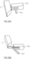
- are perspective views of an exemplary embodiment of a drive release mechanism according to the present invention.
- Corresponding parts are marked with the same reference symbols in all figures.
-
Figure 1 is a perspective semitransparent view of an exemplary embodiment of anautoinjector 1 according to the present invention. - In an exemplary embodiment, the
autoinjector 1 comprises acase 2 designed to be held by a patient, health-care provider or other user during an injection. Thecase 2 may have a generally elongate, rectangular shape and may include one or more ergonomic features (e.g., finger grooves for gripping) and/or textured surfaces or skins for preventing a user's hand from slipping while using theautoinjector 1. - In an exemplary embodiment, the
case 2 includes adoor 3 which is configurable in an open position or a closed position. In the open position, thedoor 3 provides access to a syringe carrier in thecase 2 that is adapted to hold asyringe 6 or a cartridge containing a medicament. In the closed position, thedoor 3 may be locked. As shown in the exemplary embodiment inFigure 1 , thedoor 3 may be formed on a side of thecase 2 and rotate about a transverse hinge between the open and closed positions. However, those of skill in the art will understand that thedoor 3 may be formed on any side or face of thecase 2 and may rotate, slide or translate relative to thecase 2 to open and close. - In an exemplary embodiment, a door spring may be arranged in the
case 2 to bias thedoor 3 to the open position. A door latch may be formed on thecase 2 and/or thedoor 3 to maintain thedoor 3 in the closed position. In an exemplary embodiment, the door latch may be rotated or deflected to engage/disengage thecase 2 and/or thedoor 3 to allow thedoor 3 to open and close. When thedoor 3 is in the open position, a used syringe may be removed from the syringe carrier and a new syringe may be inserted into the syringe carrier. - In an exemplary embodiment, at least one
drive spring 9 is disposed in thecase 2. In the exemplary embodiment shown inFigure 1 , twodrive springs 9 are compression springs disposed in parallel in thecase 2. Those of skill in the art will understand that other exemplary embodiments may utilize a single drive spring, and one or more tension or torsion drive springs. - In an exemplary embodiment, the drive springs 9 apply a biasing force on a plunger 10. The plunger 10 comprises a piston rod 10.1 projecting distally from a transverse beam 10.3 and two legs 10.2 projecting distally from opposing lateral portions of the transverse beam 10.3 and parallel to the piston rod 10.1. In the exemplary embodiment, each
drive spring 9 is positioned between a proximal end of thecase 2 and a distal foot 10.4 of each leg 10.2. - In an exemplary embodiment, at least one
lever 11 is hingedly coupled to thedoor 3 at a first end via apivot 12 and engages aroller 13 at a second end. Theroller 13 may be disposed in anaxial track 14 which is formed in thecase 2, and theroller 13 may be adapted to engage the distal foot 10.4 of the leg 10.2 of the plunger 10 when thedoor 3 is moved from the closed position to the open position. In another exemplary embodiment, the second end of thelever 11 may engage thetrack 14 and be axially moveable relative thereto. A projection or abutment surface may be coupled to the second end of thelever 11 and adapted to engage the distal foot 10.4 of the leg 10.2. As explained further below, thedoor 3 and thelevers 11 may be utilized as a reset mechanism. -
Figure 2 shows an exemplary embodiment of anautoinjector 1 according to the present invention. In the exemplary embodiment shown inFigure 2 , thedoor 3 is in the opened position, and aroller 13 is abutting the distal foot 10.4 of each leg 10.2. In the exemplary embodiment, each leg 10.2 includes a ratchet face 10.5 having teeth that are adapted to engage a hook 15.1 on aresilient tongue 15. Thetongue 15 may be an elongate member formed in thecase 2 which is fixed at one end and deflectable at an opposite end having the hook 15.1, and thetongue 15 may be biased toward the leg 10.2. Thus, as the leg 10.2 is moving in the proximal direction, the teeth on the ratchet face 10.5 may engage the hook 15.1 to prevent the plunger 10 from moving in the distal direction during a reset operation and/or while moving thedoor 3 from the closed position to the open position. Those of skill in the art will understand that the teeth on the ratchet face 10.5 and the hook 15.1 may have corresponding ramped engagement surfaces to reduce a force required to open thedoor 3. -
Figure 2 also shows an exemplary embodiment of guide pins 10.6 which may be formed on a proximal end of thecase 2 and project in a distal direction through holes in the transverse beam 10.3. The guide pins 10.6 may provide support and alignment for the drive springs 9. -
Figure 3 shows an exemplary embodiment of anautoinjector 1 according to the present invention. In the exemplary embodiment shown inFigure 3 , the plunger 10 has been fully translated in the proximal direction P, the drive springs 9 have been compressed, the hooks 15.1 have engaged a distal-most tooth on each ratchet face 10.5, and thedoor 3 is being closed. - Referring again to
figure 1 , theautoinjector 1 includes a trigger button (not visible in the figures) arranged on thecase 2. The trigger button serves for starting an injection process when actuated. The trigger button may be a push button, a switch, a dial (e.g., to vary needle penetration depth), etc. The trigger button may be arranged on a proximal end of thecase 2 or a side of the case. In another exemplary embodiment, the trigger button may be replaced by a push-actuated device, which is actuated when theautoinjector 1 is placed on the injection site. In an exemplary embodiment, a spring biases the trigger button relative to thecase 2. - In an exemplary embodiment, the
autoinjector 1 includes aninterlock sleeve 17 slidably disposed in thecase 2. Theinterlock sleeve 17 includes a distal end which protrudes from an aperture formed in a distal end of thecase 2. The distal end of theinterlock sleeve 17 includes an aperture 17.2 for allowing a needle to pass through during needle insertion into the injection site. The distal end of theinterlock sleeve 17 may further include an expanded contact face to support proper alignment of theautoinjector 1 on the injection site and provide additional stability during the injection. - The
interlock sleeve 17 may be biased by a spring in an extended position, which position is shown in the exemplary embodiment infigure 1 . When theautoinjector 1 is placed on the injection site, interlocksleeve 17 may be pushed in the proximal direction into a retracted position against the biasing force of the spring. -
Figures 3 and4 show an exemplary embodiment of theautoinjector 1 according to the present invention in which the trigger button is operably coupled to theinterlock sleeve 17. For example, when theinterlock sleeve 17 is in the extended position, the trigger button may be locked and prevented from actuation. When theinterlock sleeve 17 is in the retracted position, the trigger button may be unlocked and actuatable. - In an exemplary embodiment, two interlock beams 17.1 extend in the proximal direction from the distal end of the
interlock sleeve 17. In an exemplary embodiment, the interlock beams 17.1 are maintained on an inside of thecase 2, and may include abutment surfaces which engage a distal end of thecase 2 when theinterlock sleeve 17 is in the extended position. Proximal ends of the interlock beams 17.1 include ramped surfaces which engage corresponding ramped surfaces of resilient button locking beams 18 disposed in thecase 2. When theinterlock sleeve 17 moves from the extended position to the retracted position, the proximal ends of the interlock beams 17.1 cause the button locking beams 18 to deflect. - In a non-deflected state, the button locking beams 18 are adapted to engage distal ends of trigger button beams 16, which are operably coupled to the trigger button, and prevent the trigger button beams 16 from moving in the distal direction. When the button locking beams 18 are deflected, the trigger button beams 16 may move in the distal direction. The distal ends of the trigger button beams 16 are in ramped engagement with the
resilient tongues 15. Thus, axial movement of the trigger button beams 16 causes theresilient tongues 15 to deflect laterally and disengage the legs 10.2 of the plunger 10. - Thus, in the exemplary embodiment, the trigger button is actuatable when the
interlock sleeve 17 is in the retracted position. Otherwise, the trigger button is prevented from actuation, because the button locking beams 18 abut the trigger button beams 16, as shown infigures 3 and4 . - Referring again to
figure 1 , in an exemplary embodiment, adoor lock 19 may be disposed on thecase 2. Thedoor lock 19 may be a button, a switch or other component which maintains thedoor 3 in the closed position. As shown in the exemplary embodiment infigure 4 , thedoor lock 19 has a pin 19.1 which projects into the interior of thecase 2. Thedoor lock 19 may have a proximal position in which the pin 19.1 is disengages from a door hook 3.1 (shown infigure 1 ) and a distal position in which the pin 19.1 engages the door hook 3.1. Thedoor lock 19 may be biased (e.g., by a spring) in the distal position, and when the door is moved from the open position to the closed position, a ramped portion of the door hook 3.1 may move the pin 19.1 and thedoor lock 19 into the proximal position until thedoor 3 is closed, and then thedoor lock 19 may return (under the biasing force) to the distal position so that the pin 19.1 engages the door hook 3.1 and locks thedoor 3. -
Figures 5-7 show an exemplary embodiment of asyringe 6 for use with theautoinjector 1 according to the present invention. Thesyringe 6 includes abody 20 containing a medicament and acase 21 telescopically coupled to thebody 20. Thecase 21 may include an attachment (e.g., hooks, snaps, etc.) which engage a finger flange 20.1 on a proximal end of thebody 20. Aneedle shield 23 is telescopically coupled to thecase 21 and is biased toward the distal direction relative to thecase 21 by aspring 24. Theneedle shield 23 is retained in its retracted state (shown inFigure 16 ) by a pivoted clip 21.1 on thecase 21 which in a non-deflected position engages a recess in theneedle shield 23 and in a deflected position disengages the recess in theneedle shield 23. Referring toFigure 6 , aneedle 22 is disposed at a distal end of thebody 20. Aneedle boot 7 is, as shown inFigure 5 , arranged on theneedle 22, prior to use.Figure 6 shows thesyringe 6 with theneedle boot 7 removed and theneedle shield 23 in a retracted position, with theneedle 22 exposed.Figure 7 shows thesyringe 6 with theneedle shield 23 in an extended position, covering a distal tip of theneedle 22. Theneedle shield 23 may be locked in its extended position, as shown inFigure 17 , by a resilient beam 23.2 which is released and abuts thecase 21 once theshield 23 is in its fully extended position. - In an exemplary embodiment, a
data storage device 27 may be disposed on thesyringe 6 and include data, such as a type and volume of the medicament, filling and/or expiration date of the medicament, temperature of the medicament (e.g., if there is a temperature sensor on or near the syringe 4), a manufacturer of the medicament and/or theautoinjector 1, patient data (e.g., name, physician, dosing regiment, etc.), a used/unused indicator, etc. Thedata storage device 27 may interface with a wired or wireless communication device for transmitting the data to a computing device. The computing device may be used for tracking use/attributes of thesyringe 6, e.g., for compliance and/or quality control purposes. - Referring again to
figure 1 , in an exemplary embodiment, theautoinjector 1 includes aretraction collar 25 distally supporting thesyringe 6 and biased against thecase 2 in the proximal direction P by aretraction spring 26 so that thesyringe 6 is biased towards a retracted position in which theneedle 22 is covered within thecase 2. - In an exemplary embodiment, the
retraction collar 25 is utilized for removing theneedle boot 7 prior to an injection. Theretraction collar 25 includes a flange which is adapted to engage theneedle boot 7. For example, the flange may engage a proximal surface on an annular boot collar 7.1 on theneedle boot 7. In an exemplary embodiment, as thedoor 3 is moved from the open position to the closed position, when thedoor 3 is almost closed, thelevers 11 and/or therollers 13 may operably engage theretraction collar 25 to advance theretraction collar 25 in the distal direction, against the force of theretraction spring 26. Theneedle boot 7 may then be at least partially disengage from theneedle 22 and at least partially exposed through the aperture 17.2 in the distal end of theinterlock sleeve 17. As shown inFigure 18 , thesyringe assembly 6 is held in place via interference between a boss 21.2 on thesyringe case 21 and a ramped boss 2.1 on thecase 2. The force to overcome the interference is higher than the forces generated as thedoor 3 is closed; however it is lower than the drive forces during device firing. - In an exemplary embodiment, the
case 2 and/or thedoor 3 may include aviewing window 28 for allowing inspection of thesyringe 6 and its contents and state. - In an exemplary, non-illustrated embodiment a distal end of the piston rod 10.1 may comprise resilient elements which may be inwardly deflected so as to reduce an external diameter of the distal end of the piston rod 10.1. In a relaxed position of the resilient elements, the external diameter of the distal end of the piston rod 10.1 is slightly greater than an internal diameter of the proximal end of the
syringe body 20. The resilient elements may be rounded off or ramped so that they may be inwardly deflected when pushing on the proximal end of thesyringe body 20 and when a counteracting force of thesyringe body 20 exceeds a predetermined value. The proximal end of thesyringe body 20 may exhibit an internal circumferential collar slightly reducing the internal diameter of thesyringe body 20 and providing an additional detent which has to be overcome by the distal end of the piston rod 10.1 before it can enter thesyringe body 20. If the piston rod 10.1 is advanced in the distal direction, it contacts the collar. As long as thesyringe body 20 can move in the distal direction the counteracting force from thesyringe body 20 may be too low to deflect the resilient elements. Hence, the piston rod 10.1 advances thesyringe body 20 and the whole syringe for extending theneedle 22 from thecase 2 without pushing on the stopper 8. As thesyringe 6 advances theretraction spring 26 is compressed. When theneedle 22 has reached its insertion depth thesyringe 6 bottoms out against a stop in thecase 2 thereby suddenly increasing the counteracting force opposing the force from the piston rod 10.1. The resilient elements are therefore inwardly deflected by the collar disengaging the piston rod 10.1 from thesyringe body 20 and allowing it to advance further and engage the stopper 8 for displacing the medicament from thesyringe body 20. - An exemplary sequence of operation of the
autoinjector 1 is described in the following, though those of skill in the art will understand that various steps in the sequence may be conducted in any order and is not limited to the sequence described below. -
Figure 8 shows an exemplary embodiment of anautoinjector 1 according to the present invention prior to use. Thedoor 3 is locked in the closed position, because the door hook 3.1 engages the pin 19.1 on thedoor lock 19. Theinterlock sleeve 17 is in the extended position. -
Figure 9 shows an exemplary embodiment of anautoinjector 1 according to the present invention prior to use, with thedoor 3 in the open position. When thedoor lock 19 is moved from the distal position to the proximal position, the pin 19.1 disengages the door hook 3.1, and a spring may rotate thedoor 3 from the closed position. In an exemplary embodiment, the spring may be forceful enough to move thedoor 3 to the open position, or the spring may rotate thedoor 3 from the closed position and a user may be required to rotate thedoor 3 to the full open position, as shown inFigure 9 . - When the
door 3 is moved from the closed position to the open position, therollers 13 move proximally along therespective tracks 14, pushing the legs 10.2 and, thus, the plunger 10 proximally, which compresses the drive springs 9. When thedoor 3 is in the open position, the distal-most teeth on the ratchet face 10.5 of the legs 10.1 engage the hook 15.1 on theresilient tongue 15. As explained above, the teeth on the ratchet face 10.5 engaging the hook 15.1 prevent the plunger 10 from moving distally when thedoor 3 is being opened. -
Figure 10 shows an exemplary embodiment of anautoinjector 1 according to the present invention prior to use with asyringe 6. In the exemplary embodiment, thesyringe 6 is placed in a syringe carrier which is slidably disposed in thecase 2 or in a channel in thecase 2 which allows thesyringe 6 to translate relative to thecase 2. Thesyringe 6 may be aligned such that the annular boot collar 7.1 on theneedle boot 7 engages the flange on theretraction collar 25. -
Figure 11 shows an exemplary embodiment of anautoinjector 1 according to the present invention with anunused syringe 6 in thecase 2 and thedoor 3 in the closed position. As thedoor 3 is moved from the open position to the closed position, when thedoor 3 is almost closed, thelevers 11 and/or therollers 13 may operably engage theretraction collar 25 to advance theretraction collar 25 in the distal direction, against the force of theretraction spring 26. Thus, when thedoor 3 is in the closed position, theneedle boot 7 may be at least partially disengaged from theneedle 22 and at least partially exposed through the aperture 17.2 in the distal end of theinterlock sleeve 17. The user may then grip theneedle boot 7 and pull it off theneedle 22, which may remain covered by theinterlock sleeve 17. When theinterlock sleeve 17 is in the extended position, the trigger button of theautoinjector 1 is locked, because the trigger button beams 16 abut the interlock beams 17.1. -
Figure 12 shows an exemplary embodiment of anautoinjector 1 according to the present invention during use, when theautoinjector 1 has been pressed against an injection site. When theautoinjector 1 is pressed against an injection site, theinterlock sleeve 17 translates in the proximal direction relative to thecase 2. As theinterlock sleeve 17 translates proximally relative to thecase 2, the interlock beams 17.2 engage the button locking beams 18, causing the button locking beams 18 to deflect. Because the button locking beams 18 are deflected, they no longer prevent the trigger button beams 16 from moving distally relative to thecase 2, and thus the trigger button is operable. -
Figure 13 shows an exemplary embodiment of anautoinjector 1 according to the present invention during use. When the trigger button is pressed, the trigger button beams 16 move distally relative to thecase 2, and deflect thetongues 15. When thetongues 15 are deflected, the hook 15.1 disengages the ratchet faces 10.5 of the legs 10.2, and the plunger 10, under the force of the drive springs 9, moves distally relative to thecase 2. As the plunger 10 moves distally relative to thecase 2, it first engages the syringe 6 (or the syringe carrier) and pushes thesyringe 6 distally relative to thecase 2 for insertion of theneedle 22 into the injection site. Theneedle 22 passes through the aperture 17.2 in theinterlock sleeve 17, as shown infigure 13 . When the syringe 6 (or the syringe carrier) abuts a first stop in thecase 2, the remaining force in the drive springs 10 causes the plunger 10 to engage and push the stopper 8 in thesyringe 6, dispensing the medicament in thesyringe 6. In an exemplary embodiment, the plunger 10 may engage a second stop in thecase 2 to limit its movement relative to thesyringe 6 after thesyringe 6 has engaged the first stop. - In an exemplary embodiment, the
autoinjector 1 may include one or more feedback mechanisms which provide visual, audible and/or tactile feedback regarding progress of the injection. For example, when the hook 15.1 disengages the ratchet face 10.5, a clicking sound may be generated to notify the user that the injection has begun. Visual feedback may be provided, for example, through the window(s) 28 in thecase 2. - When the syringe 6 (or the syringe carrier) abuts the stop in the
case 2, theretraction spring 26 has been compressed. As shown inFigures 19A and 19B , theretraction collar 25 is held in place by theroller 13. After activation the distal foot 10.4 contacts the roller 13 (Figure 19A ) and the ramped face of the distal foot 10.4 lifts theroller 13 to a plane above the initial contact point of theroller 13 and the retraction collar 25 (Figure 19B ). This allows theretraction spring 26 to drive thesyringe 6 back in the proximal direction. Simultaneously, as transverse beam 10.3 reaches its end stop, the legs 10.2 align with a gap in thecase 2 allowing them to spring out and uncouple the transverse beam 10.3 from the drive springs 9, as shown inFigures 20A and 20B . -
Figure 14 shows an exemplary embodiment of anautoinjector 1 according to the present invention after use. When theautoinjector 1 is removed from the injection site (e.g., after a dose of the medicament has been delivered or for any other reason), theinterlock sleeve 17 returns to the extended state under the force of the spring, theretraction spring 26 exerts force on the syringe 6 (or the syringe carrier) to withdraw theneedle 22 from the injection site, and, because the trigger button has been released, the ratchet faces 10.5 engage the legs 10.2 to maintain the plunger 10 in position relative to thecase 2. For example, if theautoinjector 1 is removed from the injection site prior to delivery of the full dose of the medicament, the ratchet faces 10.5 may engage the hooks 15.1 to prevent the plunger 10 from further advancing the stopper 8. Also, after thesyringe 6 has been retracted, theneedle shield 23 is advanced to and locked in the extended position by theneedle shield spring 24, as shown inFigure 15 . Thus, when thedoor 3 is unlocked (via the door lock 19) and moved to the open position, theneedle 22 is covered by the lockedneedle shield 23 and does not present risk of needle stick injury. - Those of skill in the art will understand that modifications (additions and/or removals) of various components of the apparatuses, methods and/or systems and embodiments described herein may be made without departing from the full scope and spirit of the present invention, which encompass such modifications and any and all equivalents thereof.
- In the following, a set of items is disclosed. The items are numbered to facilitate referencing the features of one item in other items. The items form part of the disclosure of the present application and could be made subject to independent and/or dependent claims irrespective of what currently is claimed in the application and also independent of the references in brackets. We note, however, that the scope of protection is defined by the appended claims, where the following items do not constitute claims. The items are:
- 1. A syringe (6), including a body (20) containing a medicament and a case (21) telescopically coupled to the body (20), wherein a data storage device (27) including data is disposed on the syringe (6).
- 2. The syringe (6) of
item 1, wherein the data includes one or more of a type and volume of the medicament, filling and/or expiration date of the medicament, temperature of the medicament, a manufacturer of the medicament and/or an autoinjector (1) to be used with the syringe (6), patient data, a used/unused indicator. - 3. The syringe (6) of
item 2, wherein the patient data include one or more of a name, physician, dosing regimen. - 4. The syringe (6) of
item - 5. The syringe (6) according to any one of the preceding items , wherein the data storage device (27) is adapted to interface with a wired or wireless communication device for transmitting the data to a computing device.
- 6. The syringe (6) according to any one of the preceding items , wherein a needle (22) is disposed at a distal end of the body (20), the syringe (6) further comprising a needle shield (23) telescopically coupled to the case (21) and biased toward a distal direction relative to the case (21) by a spring (24), wherein the needle shield (23) is retained in a retracted state by a pivoted clip (21.1) on the case (21) which in a non-deflected position engages a recess in the needle shield (23) and in a deflected position disengages the recess in the needle shield (23), wherein a needle boot (7) is arranged on the needle (22) prior to use.
- 7. The syringe (6) according to
item 6, wherein the case (21) includes an attachment which engages a finger flange (20.1) on a proximal end of the body (20). - 8. The syringe (6) of
item 7, wherein the attachment comprises hooks or snaps. - 9. The syringe (6) according to any one of the preceding items , wherein the needle shield (23) is adapted to be locked in its extended position by a resilient beam (23.2) which is released and abuts the case (21) once the shield (23) is in its fully extended position.
- 10.A system comprising the syringe (6) according to any one of the
items 5 to 9 and a computing device adapted to track use/attributes of the syringe (6). - 11.A system comprising a syringe (6) according to any one of the preceding items and an auto-injector (1) comprising:
- a case (2)
- a door (3) hingedly coupled to the case (2) and having an open position and a closed position;
- at least one drive spring (9);
- characterized in a plunger (10) slidably disposed in the case (2); and
- the at least one drive spring (9) applying a biasing force on the plunger (10) relative to the case (2);
- wherein the door (3) is operably coupled to the plunger (10), and
- wherein rotation of the door (3) from the closed position to the open position moves the plunger (10) from a distal position in the case (2) to a proximal position in the case (2) and compresses the at least one drive spring (9),
- the autoinjector (1) further comprising:
a trigger button disposed on the case (2) and operably coupled to the plunger (10).
- 12. The system of
item 11, wherein the autoinjector (1) includes a retraction collar (25) distally supporting the syringe (6) and biased against the case (2) in the proximal direction (P) by a retraction spring (26) so that the syringe (6) is biased towards a retracted position in which the needle (22) is covered within the case (2). - 13. The system of
item 12, wherein the retraction collar (25) includes a flange which is adapted to engage the needle boot (7) for removing the needle boot (7) prior to an injection. - 14. The system of
item 13, wherein the flange is adapted to engage a proximal surface on an annular boot collar (7.1) on the needle boot (7). - 15. The system of
item - at least one lever (11) hingedly coupled to the door (3);
- at least one roller (13) rotatably coupled to the lever (11);
- an interlock sleeve (17) slidably disposed in the case (2) and having an extended position and a retracted position relative to the case (2),
- wherein as the door (3) is moved from the open position to the closed position, when the door (3) is almost closed, the levers (11) and/or the rollers (13) operably engage the retraction collar (25) to advance the retraction collar (25) in the distal direction against the force of the retraction spring (26) thus at least partially disengaging the needle boot (7) from the needle (22) and at least partially exposing it through an aperture (17.2) in the distal end of the interlock sleeve (17), wherein the syringe (6) is held in place via interference between a boss (21.2) on the syringe case (21) and a ramped boss (2.1) on the autoinjector case (2), wherein the force to overcome the interference is higher than the forces generated as the door (3) is closed but lower than the drive forces during device firing.
Claims (15)
- An autoinjector (1) comprising:a case (2);a door (3) hingedly coupled to the case (2) and having an open position and a closed position;at least one drive spring (9); anda plunger (10) slidably disposed in the case (2),wherein the at least one drive spring (9) is configured to apply a biasing force on the plunger (10) relative to the case (2).
- The autoinjector (1) according to claim 1, wherein the door (3) is operably coupled to the plunger (10).
- The autoinjector (1) according to claim 2, wherein a rotation of the door (3) from the closed position to the open position moves the plunger (10) from a distal position in the case (2) to a proximal position in the case (2).
- The autoinjector (1) according to any one of the preceding claims, wherein a door latch is formed on the case (2) and/or the door (3) to maintain the door (3) in the closed position.
- The autoinjector (1) according to any one of the preceding claims, wherein a door lock (19) is disposed on the case (2).
- The autoinjector (1) according to claim 5, wherein the door lock (19) is a button, a switch or another component capable of maintaining the door (3) in the closed position.
- The autoinjector (1) according any one of the preceding claims, further comprising an interlock sleeve (17) slidably disposed in the case (2), having an extended position and a retracted position relative to the case (2).
- The autoinjector (1) according to claim 7, wherein the interlock sleeve (17) includes a distal end which protrudes from an aperture formed in a distal end of the case (2).
- The autoinjector (1) according to claim 8, wherein the distal end of the interlock sleeve (17) includes an aperture (17.2) for allowing a needle to pass through during needle insertion into the injection site.
- The autoinjector (1) according to any one of claims 7 to 9, wherein the interlock sleeve (17) is biased by a spring in the extended position.
- The autoinjector (1) according to any one of claims 7 to 10, wherein, when the autoinjector is placed on the injection site, the interlock sleeve (17) is configured to translate in a proximal direction relative to the case (2), e.g. into the retracted position.
- The autoinjector (1) according to claim 10 or 11, wherein, when the autoinjector is removed from the injection site, the interlock sleeve (17) returns to the extended position under the force of the spring.
- The autoinjector (1) according any one of the preceding claims, wherein the case (2) further comprises a syringe carrier configured to hold a syringe (6) or a cartridge containing a medicament.
- The autoinjector (1) according to claim 13, further comprising a retraction collar (25) adapted to engage a needle boot (7) of the syringe (6).
- The autoinjector (1) according to any one of the preceding claims, wherein the case (2) has a generally elongate, rectangular shape and/or wherein the case (2) includes one or more ergonomic features and/or textured surfaces or skins for preventing a user's hand from slipping while using the autoinjector.
Applications Claiming Priority (4)
| Application Number | Priority Date | Filing Date | Title |
|---|---|---|---|
| EP12191442.8A EP2727617A1 (en) | 2012-11-06 | 2012-11-06 | Autoinjector |
| PCT/EP2013/072897 WO2014072237A1 (en) | 2012-11-06 | 2013-11-04 | Autoinjector |
| EP17187528.9A EP3275481B1 (en) | 2012-11-06 | 2013-11-04 | Autoinjector |
| EP13786233.0A EP2916888B1 (en) | 2012-11-06 | 2013-11-04 | Autoinjector |
Related Parent Applications (3)
| Application Number | Title | Priority Date | Filing Date |
|---|---|---|---|
| EP17187528.9A Division EP3275481B1 (en) | 2012-11-06 | 2013-11-04 | Autoinjector |
| EP17187528.9A Division-Into EP3275481B1 (en) | 2012-11-06 | 2013-11-04 | Autoinjector |
| EP13786233.0A Division EP2916888B1 (en) | 2012-11-06 | 2013-11-04 | Autoinjector |
Publications (2)
| Publication Number | Publication Date |
|---|---|
| EP4556038A2 true EP4556038A2 (en) | 2025-05-21 |
| EP4556038A3 EP4556038A3 (en) | 2025-08-06 |
Family
ID=47172467
Family Applications (4)
| Application Number | Title | Priority Date | Filing Date |
|---|---|---|---|
| EP12191442.8A Ceased EP2727617A1 (en) | 2012-11-06 | 2012-11-06 | Autoinjector |
| EP13786233.0A Active EP2916888B1 (en) | 2012-11-06 | 2013-11-04 | Autoinjector |
| EP25158096.5A Pending EP4556038A3 (en) | 2012-11-06 | 2013-11-04 | Autoinjector |
| EP17187528.9A Active EP3275481B1 (en) | 2012-11-06 | 2013-11-04 | Autoinjector |
Family Applications Before (2)
| Application Number | Title | Priority Date | Filing Date |
|---|---|---|---|
| EP12191442.8A Ceased EP2727617A1 (en) | 2012-11-06 | 2012-11-06 | Autoinjector |
| EP13786233.0A Active EP2916888B1 (en) | 2012-11-06 | 2013-11-04 | Autoinjector |
Family Applications After (1)
| Application Number | Title | Priority Date | Filing Date |
|---|---|---|---|
| EP17187528.9A Active EP3275481B1 (en) | 2012-11-06 | 2013-11-04 | Autoinjector |
Country Status (6)
| Country | Link |
|---|---|
| US (7) | US10391246B2 (en) |
| EP (4) | EP2727617A1 (en) |
| JP (1) | JP6415441B2 (en) |
| CN (1) | CN104768594B (en) |
| DK (1) | DK2916888T3 (en) |
| WO (1) | WO2014072237A1 (en) |
Families Citing this family (50)
| Publication number | Priority date | Publication date | Assignee | Title |
|---|---|---|---|---|
| US8157769B2 (en) | 2009-09-15 | 2012-04-17 | Medimop Medical Projects Ltd. | Cartridge insertion assembly for drug delivery system |
| EP2601992A1 (en) | 2011-12-08 | 2013-06-12 | Sanofi-Aventis Deutschland GmbH | Syringe carrier |
| EP2727617A1 (en) | 2012-11-06 | 2014-05-07 | Sanofi-Aventis Deutschland GmbH | Autoinjector |
| EP2777684A1 (en) | 2013-03-14 | 2014-09-17 | Sanofi-Aventis Deutschland GmbH | Medicament container carrier and adapter |
| CA2952167C (en) | 2014-06-13 | 2023-06-13 | Aterica Inc. | System and device for management of medication delivery devices |
| US9775957B2 (en) * | 2015-01-16 | 2017-10-03 | Becton, Dickinson And Company | Smart module for injection devices |
| TW201700118A (en) | 2015-06-03 | 2017-01-01 | 賽諾菲阿凡提斯德意志有限公司 | Drug delivery device (3) |
| TW201709941A (en) | 2015-06-03 | 2017-03-16 | 賽諾菲阿凡提斯德意志有限公司 | Sound indicator (2) |
| TW201711713A (en) | 2015-06-03 | 2017-04-01 | 賽諾菲阿凡提斯德意志有限公司 | Drug delivery device |
| TW201700117A (en) | 2015-06-03 | 2017-01-01 | 賽諾菲阿凡提斯德意志有限公司 | Syringe bracket and assembly method for autoinjector |
| TW201709940A (en) | 2015-06-03 | 2017-03-16 | 賽諾菲阿凡提斯德意志有限公司 | Sound indicator (1) |
| TW201707737A (en) * | 2015-06-03 | 2017-03-01 | 賽諾菲阿凡提斯德意志有限公司 | Drug delivery device (1) |
| TW201705994A (en) | 2015-06-03 | 2017-02-16 | 賽諾菲阿凡提斯德意志有限公司 | Automatic syringe and assembly method |
| CN107683158B (en) | 2015-06-04 | 2021-05-14 | 麦迪麦珀医疗工程有限公司 | Cartridge Insertion for Drug Release Devices |
| WO2017087888A1 (en) | 2015-11-18 | 2017-05-26 | President And Fellows Of Harvard College | Systems and methods for monitoring, managing, and treating asthma and anaphylaxis |
| CN108778369B (en) * | 2016-03-18 | 2021-05-25 | 医疗部件有限公司 | Huber safety needle |
| GB2549750A (en) * | 2016-04-27 | 2017-11-01 | Owen Mumford Ltd | Medicament delivery device |
| US10376656B2 (en) * | 2016-05-18 | 2019-08-13 | Portal Instruments, Inc. | Side-angle decapping of pre-filled syringe |
| WO2017210448A1 (en) | 2016-06-02 | 2017-12-07 | Medimop Medical Projects Ltd. | Three position needle retraction |
| FR3053893B1 (en) * | 2016-07-13 | 2018-07-27 | Laboratoire Aguettant | MEDICAL DEVICE COMPRISING A PACKAGING AND A PRE-FILLED SYRINGE DISPOSED IN THE PACKAGING |
| CN113577438B (en) * | 2016-08-01 | 2023-05-23 | 西医药服务以色列有限公司 | Partial door closing prevention spring |
| WO2018068958A1 (en) * | 2016-10-11 | 2018-04-19 | H. Lundbeck A/S | Needle shield with reduceable needle hole |
| KR102110292B1 (en) * | 2017-01-20 | 2020-05-14 | 엘.쥐.피. 테크노로지 홀딩스 엘엘씨 | Automatic syringe device |
| JP7254022B2 (en) * | 2017-02-06 | 2023-04-07 | サノフィ-アベンティス・ドイチュラント・ゲゼルシャフト・ミット・ベシュレンクテル・ハフツング | Assembly nest for pen injection device with locking feature |
| US20180263747A1 (en) * | 2017-03-14 | 2018-09-20 | Desvac | Apparatus and method for a single sensor action plate |
| WO2018222521A1 (en) | 2017-05-30 | 2018-12-06 | West Pharma. Services IL, Ltd. | Modular drive train for wearable injector |
| EP4527435A3 (en) | 2017-11-03 | 2025-05-14 | Sanofi | Drug delivery device |
| WO2019086563A1 (en) | 2017-11-03 | 2019-05-09 | Sanofi | Drug delivery device |
| CN114470420B (en) | 2017-12-22 | 2024-08-27 | 西氏医药包装(以色列)有限公司 | Syringes for different sized cartridges |
| EP3740266A4 (en) | 2018-01-19 | 2021-10-13 | Birya Biotech, Inc. | TOOL FOR THE MAINTENANCE OF A AUTO-INJECTOR |
| WO2019191110A1 (en) | 2018-03-27 | 2019-10-03 | Quio Technologies Llc | Systems and methods for automatically ejecting a dose cassette of an autoinjector |
| GB2577682B (en) * | 2018-09-28 | 2021-10-20 | Owen Mumford Ltd | Auto-injector |
| USD958330S1 (en) | 2018-12-21 | 2022-07-19 | Janssen Pharmaceuticals, Inc. | Injection device accessory |
| GB2580141B (en) * | 2018-12-21 | 2023-04-12 | Janssen Pharmaceuticals Inc | Accessory for an injection device including a grip for a needle cap |
| GB2580133B (en) * | 2018-12-21 | 2023-04-12 | Janssen Pharmaceuticals Inc | Accessory including a slot for a flange of an injection device |
| GB2580154A (en) * | 2018-12-21 | 2020-07-15 | Janssen Pharmaceuticals Inc | Accessory for an injection device including an exposed cap remover |
| GB2580142B (en) | 2018-12-21 | 2023-04-12 | Janssen Pharmaceuticals Inc | Accessory for an injection including a pivotable cover |
| US11724035B2 (en) * | 2019-07-31 | 2023-08-15 | Janssen Pharmaceuticals, Inc. | Injection device with ergonomic housing form factor |
| US11511044B2 (en) | 2019-09-16 | 2022-11-29 | Carefusion 303, Inc. | Sequenced syringe assembly |
| GB2589548B (en) * | 2019-09-27 | 2022-09-07 | Owen Mumford Ltd | Auto-Injector |
| GB2591977B (en) * | 2019-09-27 | 2022-03-16 | Owen Mumford Ltd | Auto-Injector |
| CN111150906B (en) * | 2020-02-24 | 2020-09-29 | 苏州恒瑞宏远医疗科技有限公司 | A two-step automatic injection device |
| CN114602004B (en) * | 2020-12-04 | 2026-03-17 | 武田药品工业株式会社 | Assistive devices for self-injectors |
| USD965148S1 (en) * | 2021-01-20 | 2022-09-27 | Shenzhen DJ Innovation Industry Co., Ltd | Hydra needle |
| GB2604586B (en) * | 2021-02-28 | 2024-03-13 | Owen Mumford Ltd | Auto-injector housing latch |
| GB2604585B (en) * | 2021-02-28 | 2023-06-21 | Owen Mumford Ltd | Auto-injector plunger driver latch |
| US20240416039A1 (en) * | 2021-10-27 | 2024-12-19 | Medmix Switzerland Ag | Autoinjector |
| US20250352719A1 (en) * | 2022-06-23 | 2025-11-20 | Bio Health Frontiers, Inc. | Portable Mechanical Syringe Pump with Universal Syringe Interface |
| EP4580705A1 (en) * | 2022-09-01 | 2025-07-09 | Janssen Biotech, Inc. | Reusable large volume injection aid |
| WO2026046932A1 (en) * | 2024-08-26 | 2026-03-05 | Astrazeneca Ab | Reusable auto-injector |
Family Cites Families (43)
| Publication number | Priority date | Publication date | Assignee | Title |
|---|---|---|---|---|
| US4020836A (en) | 1975-05-14 | 1977-05-03 | James Robert Cunningham | Apparatus for medical injections |
| GB2019322A (en) | 1978-04-14 | 1979-10-31 | Soremo Sa | Improvements in the marking and personalising of articles |
| JPS5931889Y2 (en) | 1978-04-17 | 1984-09-07 | ソニー株式会社 | Lid opening/closing device |
| JPS54155000U (en) | 1978-04-17 | 1979-10-27 | ||
| JPS54152606A (en) | 1978-05-23 | 1979-12-01 | Nippon Kokan Kk <Nkk> | Overlapped skimmer |
| US4430079A (en) * | 1978-11-08 | 1984-02-07 | Minnesota Mining And Manufacturing Company | Fluid dispensing device |
| US4681566A (en) * | 1984-11-30 | 1987-07-21 | Strato Medical Corporation | Infusion device |
| US5211626A (en) * | 1987-05-01 | 1993-05-18 | Product Innovation Holdings Ltd. | Medical infusion apparatus |
| US5383865A (en) | 1993-03-15 | 1995-01-24 | Eli Lilly And Company | Medication dispensing device |
| FR2733155B1 (en) | 1995-04-18 | 1997-09-19 | Tebro | RECHARGEABLE SELF-INJECTOR |
| WO1998015307A1 (en) | 1996-10-09 | 1998-04-16 | Equidyne Systems,Inc. | Hypodermic jet injector |
| US6517517B1 (en) | 2000-06-08 | 2003-02-11 | Mayo Foundation For Medical Education And Research | Automated injection device for administration of liquid medicament |
| US6979316B1 (en) * | 2002-05-23 | 2005-12-27 | Seedlings Life Science Ventures Llc | Apparatus and method for rapid auto-injection of medication |
| AU2003280270B2 (en) * | 2002-11-25 | 2008-01-24 | Tecpharma Licensing Ag | Injection apparatus comprising a needle-protecting device |
| GB0229345D0 (en) | 2002-12-17 | 2003-01-22 | Safe T Ltd | Hollow needle applicators |
| US6926694B2 (en) | 2003-05-09 | 2005-08-09 | Medsolve Technologies, Llc | Apparatus and method for delivery of therapeutic and/or diagnostic agents |
| AU2004249238A1 (en) * | 2003-06-20 | 2004-12-29 | Allergan, Inc. | Needless injectors |
| US20050027255A1 (en) | 2003-07-31 | 2005-02-03 | Sid Technologies, Llc | Automatic injector |
| CA2762072C (en) * | 2005-02-01 | 2017-08-29 | Intelliject, Inc. | Devices, systems, and methods for medicament delivery |
| US7955304B2 (en) | 2005-07-15 | 2011-06-07 | Shl Group Ab | Injector |
| FR2899482A1 (en) | 2006-04-11 | 2007-10-12 | Becton Dickinson France Soc Pa | AUTOMATIC INJECTION DEVICE |
| ES2657483T3 (en) | 2007-03-09 | 2018-03-05 | Eli Lilly And Company | Delay mechanism for an automatic injection device |
| WO2009037141A1 (en) | 2007-09-18 | 2009-03-26 | Shl Group Ab | Automatic injection device with needle insertion |
| US8956331B2 (en) * | 2007-11-12 | 2015-02-17 | Bang & Olufsen Medicom A/S | Auto injector with a rotatable release shaft |
| PL2229201T3 (en) * | 2007-12-31 | 2012-10-31 | Novo Nordisk As | Electronically monitored injection device |
| CN101977645B (en) * | 2008-04-10 | 2013-01-30 | 松下电器产业株式会社 | drug delivery device |
| US8556862B2 (en) | 2008-09-18 | 2013-10-15 | Becton Dickinson And Company | Needle mounting feature for ensuring proper reconstitution sequence |
| CN102264417B (en) | 2008-10-29 | 2014-01-01 | Shl集团有限责任公司 | Injection device |
| JP5487489B2 (en) * | 2008-11-14 | 2014-05-07 | パナソニックヘルスケア株式会社 | Carrying case and syringe system including the same |
| GB0821492D0 (en) * | 2008-11-25 | 2008-12-31 | Team Holdings Uk Ltd | Integrated auto-injector cartridge system |
| EP2238999A1 (en) * | 2009-04-02 | 2010-10-13 | Vincent Pongpairochana | Automatic injection device |
| TWI393578B (en) | 2009-07-07 | 2013-04-21 | 瑞健集團股份有限公司 | Injection device |
| WO2011032956A2 (en) | 2009-09-18 | 2011-03-24 | Sanofi-Aventis Deutschland Gmbh | Stopper for sealing a compartment of a medicament container |
| EP3023114A1 (en) | 2009-10-08 | 2016-05-25 | SHL Group AB | Medicament delivery device |
| US20110123314A1 (en) | 2009-11-21 | 2011-05-26 | Tyson York Winarski | Apparatus and method for forced convection of seawater |
| EP2364741A1 (en) | 2010-03-09 | 2011-09-14 | Sanofi-Aventis Deutschland GmbH | Interlock mechanism for defining an operation sequence of an auto-injector |
| US10045911B2 (en) * | 2010-06-25 | 2018-08-14 | Genetronics, Inc. | Intradermal injection device |
| EP2646072A1 (en) | 2010-11-29 | 2013-10-09 | Sanofi-Aventis Deutschland GmbH | Auto-injector device with a medicated module |
| EP2468338A1 (en) | 2010-12-21 | 2012-06-27 | Sanofi-Aventis Deutschland GmbH | Auto-injector |
| EP2468341A1 (en) | 2010-12-21 | 2012-06-27 | Sanofi-Aventis Deutschland GmbH | Auto-injector |
| EP2468340A1 (en) * | 2010-12-21 | 2012-06-27 | Sanofi-Aventis Deutschland GmbH | Auto injector with an interlock switch detecting the position of the needle shroud |
| EP2468328A1 (en) | 2010-12-21 | 2012-06-27 | Sanofi-Aventis Deutschland GmbH | Auto-injector |
| EP2727617A1 (en) | 2012-11-06 | 2014-05-07 | Sanofi-Aventis Deutschland GmbH | Autoinjector |
-
2012
- 2012-11-06 EP EP12191442.8A patent/EP2727617A1/en not_active Ceased
-
2013
- 2013-11-04 WO PCT/EP2013/072897 patent/WO2014072237A1/en not_active Ceased
- 2013-11-04 JP JP2015540143A patent/JP6415441B2/en active Active
- 2013-11-04 EP EP13786233.0A patent/EP2916888B1/en active Active
- 2013-11-04 EP EP25158096.5A patent/EP4556038A3/en active Pending
- 2013-11-04 DK DK13786233.0T patent/DK2916888T3/en active
- 2013-11-04 CN CN201380057564.2A patent/CN104768594B/en active Active
- 2013-11-04 EP EP17187528.9A patent/EP3275481B1/en active Active
- 2013-11-04 US US14/440,819 patent/US10391246B2/en active Active
-
2019
- 2019-07-10 US US16/507,291 patent/US11344676B2/en active Active
-
2022
- 2022-04-21 US US17/726,381 patent/US12076535B2/en active Active
-
2023
- 2023-07-06 US US18/218,884 patent/US11957879B2/en active Active
-
2024
- 2024-03-14 US US18/605,302 patent/US12558484B2/en active Active
-
2025
- 2025-03-19 US US19/083,818 patent/US20250213796A1/en active Pending
- 2025-03-19 US US19/083,768 patent/US20250213795A1/en active Pending
Non-Patent Citations (1)
| Title |
|---|
| "Remington's Pharmaceutical Sciences", vol. 17, 1985, MARK PUBLISHING COMPANY |
Also Published As
| Publication number | Publication date |
|---|---|
| EP2916888A1 (en) | 2015-09-16 |
| EP4556038A3 (en) | 2025-08-06 |
| EP3275481B1 (en) | 2025-03-26 |
| US11957879B2 (en) | 2024-04-16 |
| US20250213796A1 (en) | 2025-07-03 |
| DK2916888T3 (en) | 2018-01-08 |
| EP2916888B1 (en) | 2017-10-04 |
| WO2014072237A1 (en) | 2014-05-15 |
| US20230347054A1 (en) | 2023-11-02 |
| EP3275481C0 (en) | 2025-03-26 |
| CN104768594B (en) | 2018-03-16 |
| US10391246B2 (en) | 2019-08-27 |
| EP2727617A1 (en) | 2014-05-07 |
| US20220241507A1 (en) | 2022-08-04 |
| HK1210071A1 (en) | 2016-04-15 |
| US12076535B2 (en) | 2024-09-03 |
| US11344676B2 (en) | 2022-05-31 |
| US20190328972A1 (en) | 2019-10-31 |
| US20240293621A1 (en) | 2024-09-05 |
| CN104768594A (en) | 2015-07-08 |
| US20150297833A1 (en) | 2015-10-22 |
| JP6415441B2 (en) | 2018-10-31 |
| EP3275481A1 (en) | 2018-01-31 |
| JP2015536715A (en) | 2015-12-24 |
| US20250213795A1 (en) | 2025-07-03 |
| US12558484B2 (en) | 2026-02-24 |
Similar Documents
| Publication | Publication Date | Title |
|---|---|---|
| US12558484B2 (en) | Autoinjector | |
| US20220211951A1 (en) | Autoinjector | |
| US10814074B2 (en) | Autoinjector | |
| AU2014289352B2 (en) | Autoinjector | |
| AU2014289349B2 (en) | Autoinjector | |
| EP2823836A1 (en) | Autoinjector | |
| DK2906276T3 (en) | MEDICINE SUPPLY DEVICE WITH USE INDICATOR | |
| HK1210071B (en) | Autoinjector | |
| HK1218400B (en) | Autoinjector |
Legal Events
| Date | Code | Title | Description |
|---|---|---|---|
| PUAI | Public reference made under article 153(3) epc to a published international application that has entered the european phase |
Free format text: ORIGINAL CODE: 0009012 |
|
| STAA | Information on the status of an ep patent application or granted ep patent |
Free format text: STATUS: THE APPLICATION HAS BEEN PUBLISHED |
|
| AC | Divisional application: reference to earlier application |
Ref document number: 2916888 Country of ref document: EP Kind code of ref document: P Ref document number: 3275481 Country of ref document: EP Kind code of ref document: P |
|
| AK | Designated contracting states |
Kind code of ref document: A2 Designated state(s): AL AT BE BG CH CY CZ DE DK EE ES FI FR GB GR HR HU IE IS IT LI LT LU LV MC MK MT NL NO PL PT RO RS SE SI SK SM TR |
|
| REG | Reference to a national code |
Ref country code: DE Ref legal event code: R079 Free format text: PREVIOUS MAIN CLASS: A61M0005500000 Ipc: A61M0005200000 |
|
| PUAL | Search report despatched |
Free format text: ORIGINAL CODE: 0009013 |
|
| AK | Designated contracting states |
Kind code of ref document: A3 Designated state(s): AL AT BE BG CH CY CZ DE DK EE ES FI FR GB GR HR HU IE IS IT LI LT LU LV MC MK MT NL NO PL PT RO RS SE SI SK SM TR |
|
| RIC1 | Information provided on ipc code assigned before grant |
Ipc: A61M 5/20 20060101AFI20250703BHEP Ipc: A61M 5/50 20060101ALI20250703BHEP Ipc: A61M 5/32 20060101ALN20250703BHEP Ipc: A61M 5/46 20060101ALN20250703BHEP Ipc: A61M 5/31 20060101ALN20250703BHEP |
|
| STAA | Information on the status of an ep patent application or granted ep patent |
Free format text: STATUS: REQUEST FOR EXAMINATION WAS MADE |
|
| 17P | Request for examination filed |
Effective date: 20260204 |
|
| STAA | Information on the status of an ep patent application or granted ep patent |
Free format text: STATUS: EXAMINATION IS IN PROGRESS |
|
| 17Q | First examination report despatched |
Effective date: 20260512 |