EP2364741A1 - Interlock mechanism for defining an operation sequence of an auto-injector - Google Patents
Interlock mechanism for defining an operation sequence of an auto-injector Download PDFInfo
- Publication number
- EP2364741A1 EP2364741A1 EP10155958A EP10155958A EP2364741A1 EP 2364741 A1 EP2364741 A1 EP 2364741A1 EP 10155958 A EP10155958 A EP 10155958A EP 10155958 A EP10155958 A EP 10155958A EP 2364741 A1 EP2364741 A1 EP 2364741A1
- Authority
- EP
- European Patent Office
- Prior art keywords
- auto
- injector
- spring
- syringe
- proximal
- Prior art date
- Legal status (The legal status is an assumption and is not a legal conclusion. Google has not performed a legal analysis and makes no representation as to the accuracy of the status listed.)
- Ceased
Links
Images


Classifications
-
- A—HUMAN NECESSITIES
- A61—MEDICAL OR VETERINARY SCIENCE; HYGIENE
- A61M—DEVICES FOR INTRODUCING MEDIA INTO, OR ONTO, THE BODY; DEVICES FOR TRANSDUCING BODY MEDIA OR FOR TAKING MEDIA FROM THE BODY; DEVICES FOR PRODUCING OR ENDING SLEEP OR STUPOR
- A61M5/00—Devices for bringing media into the body in a subcutaneous, intra-vascular or intramuscular way; Accessories therefor, e.g. filling or cleaning devices, arm-rests
- A61M5/178—Syringes
- A61M5/31—Details
- A61M5/32—Needles; Details of needles pertaining to their connection with syringe or hub; Accessories for bringing the needle into, or holding the needle on, the body; Devices for protection of needles
- A61M5/3202—Devices for protection of the needle before use, e.g. caps
- A61M5/3204—Needle cap remover, i.e. devices to dislodge protection cover from needle or needle hub, e.g. deshielding devices
-
- A—HUMAN NECESSITIES
- A61—MEDICAL OR VETERINARY SCIENCE; HYGIENE
- A61M—DEVICES FOR INTRODUCING MEDIA INTO, OR ONTO, THE BODY; DEVICES FOR TRANSDUCING BODY MEDIA OR FOR TAKING MEDIA FROM THE BODY; DEVICES FOR PRODUCING OR ENDING SLEEP OR STUPOR
- A61M5/00—Devices for bringing media into the body in a subcutaneous, intra-vascular or intramuscular way; Accessories therefor, e.g. filling or cleaning devices, arm-rests
- A61M5/178—Syringes
- A61M5/20—Automatic syringes, e.g. with automatically actuated piston rod, with automatic needle injection, filling automatically
- A61M5/2033—Spring-loaded one-shot injectors with or without automatic needle insertion
-
- A—HUMAN NECESSITIES
- A61—MEDICAL OR VETERINARY SCIENCE; HYGIENE
- A61M—DEVICES FOR INTRODUCING MEDIA INTO, OR ONTO, THE BODY; DEVICES FOR TRANSDUCING BODY MEDIA OR FOR TAKING MEDIA FROM THE BODY; DEVICES FOR PRODUCING OR ENDING SLEEP OR STUPOR
- A61M5/00—Devices for bringing media into the body in a subcutaneous, intra-vascular or intramuscular way; Accessories therefor, e.g. filling or cleaning devices, arm-rests
- A61M5/178—Syringes
- A61M5/24—Ampoule syringes, i.e. syringes with needle for use in combination with replaceable ampoules or carpules, e.g. automatic
-
- A—HUMAN NECESSITIES
- A61—MEDICAL OR VETERINARY SCIENCE; HYGIENE
- A61M—DEVICES FOR INTRODUCING MEDIA INTO, OR ONTO, THE BODY; DEVICES FOR TRANSDUCING BODY MEDIA OR FOR TAKING MEDIA FROM THE BODY; DEVICES FOR PRODUCING OR ENDING SLEEP OR STUPOR
- A61M5/00—Devices for bringing media into the body in a subcutaneous, intra-vascular or intramuscular way; Accessories therefor, e.g. filling or cleaning devices, arm-rests
- A61M5/178—Syringes
- A61M5/20—Automatic syringes, e.g. with automatically actuated piston rod, with automatic needle injection, filling automatically
- A61M2005/2006—Having specific accessories
- A61M2005/202—Having specific accessories cocking means, e.g. to bias the main drive spring of an injector
-
- A—HUMAN NECESSITIES
- A61—MEDICAL OR VETERINARY SCIENCE; HYGIENE
- A61M—DEVICES FOR INTRODUCING MEDIA INTO, OR ONTO, THE BODY; DEVICES FOR TRANSDUCING BODY MEDIA OR FOR TAKING MEDIA FROM THE BODY; DEVICES FOR PRODUCING OR ENDING SLEEP OR STUPOR
- A61M5/00—Devices for bringing media into the body in a subcutaneous, intra-vascular or intramuscular way; Accessories therefor, e.g. filling or cleaning devices, arm-rests
- A61M5/178—Syringes
- A61M5/20—Automatic syringes, e.g. with automatically actuated piston rod, with automatic needle injection, filling automatically
- A61M2005/206—With automatic needle insertion
-
- A—HUMAN NECESSITIES
- A61—MEDICAL OR VETERINARY SCIENCE; HYGIENE
- A61M—DEVICES FOR INTRODUCING MEDIA INTO, OR ONTO, THE BODY; DEVICES FOR TRANSDUCING BODY MEDIA OR FOR TAKING MEDIA FROM THE BODY; DEVICES FOR PRODUCING OR ENDING SLEEP OR STUPOR
- A61M5/00—Devices for bringing media into the body in a subcutaneous, intra-vascular or intramuscular way; Accessories therefor, e.g. filling or cleaning devices, arm-rests
- A61M5/178—Syringes
- A61M5/20—Automatic syringes, e.g. with automatically actuated piston rod, with automatic needle injection, filling automatically
- A61M2005/2073—Automatic syringes, e.g. with automatically actuated piston rod, with automatic needle injection, filling automatically preventing premature release, e.g. by making use of a safety lock
- A61M2005/208—Release is possible only when device is pushed against the skin, e.g. using a trigger which is blocked or inactive when the device is not pushed against the skin
-
- A—HUMAN NECESSITIES
- A61—MEDICAL OR VETERINARY SCIENCE; HYGIENE
- A61M—DEVICES FOR INTRODUCING MEDIA INTO, OR ONTO, THE BODY; DEVICES FOR TRANSDUCING BODY MEDIA OR FOR TAKING MEDIA FROM THE BODY; DEVICES FOR PRODUCING OR ENDING SLEEP OR STUPOR
- A61M5/00—Devices for bringing media into the body in a subcutaneous, intra-vascular or intramuscular way; Accessories therefor, e.g. filling or cleaning devices, arm-rests
- A61M5/178—Syringes
- A61M5/20—Automatic syringes, e.g. with automatically actuated piston rod, with automatic needle injection, filling automatically
- A61M2005/2086—Automatic syringes, e.g. with automatically actuated piston rod, with automatic needle injection, filling automatically having piston damping means, e.g. axially or rotationally acting retarders
-
- A—HUMAN NECESSITIES
- A61—MEDICAL OR VETERINARY SCIENCE; HYGIENE
- A61M—DEVICES FOR INTRODUCING MEDIA INTO, OR ONTO, THE BODY; DEVICES FOR TRANSDUCING BODY MEDIA OR FOR TAKING MEDIA FROM THE BODY; DEVICES FOR PRODUCING OR ENDING SLEEP OR STUPOR
- A61M5/00—Devices for bringing media into the body in a subcutaneous, intra-vascular or intramuscular way; Accessories therefor, e.g. filling or cleaning devices, arm-rests
- A61M5/178—Syringes
- A61M5/24—Ampoule syringes, i.e. syringes with needle for use in combination with replaceable ampoules or carpules, e.g. automatic
- A61M2005/2403—Ampoule inserted into the ampoule holder
- A61M2005/2407—Ampoule inserted into the ampoule holder from the rear
-
- A—HUMAN NECESSITIES
- A61—MEDICAL OR VETERINARY SCIENCE; HYGIENE
- A61M—DEVICES FOR INTRODUCING MEDIA INTO, OR ONTO, THE BODY; DEVICES FOR TRANSDUCING BODY MEDIA OR FOR TAKING MEDIA FROM THE BODY; DEVICES FOR PRODUCING OR ENDING SLEEP OR STUPOR
- A61M5/00—Devices for bringing media into the body in a subcutaneous, intra-vascular or intramuscular way; Accessories therefor, e.g. filling or cleaning devices, arm-rests
- A61M5/178—Syringes
- A61M5/24—Ampoule syringes, i.e. syringes with needle for use in combination with replaceable ampoules or carpules, e.g. automatic
- A61M2005/2485—Ampoule holder connected to rest of syringe
- A61M2005/2496—Ampoule holder connected to rest of syringe via pivot
-
- A—HUMAN NECESSITIES
- A61—MEDICAL OR VETERINARY SCIENCE; HYGIENE
- A61M—DEVICES FOR INTRODUCING MEDIA INTO, OR ONTO, THE BODY; DEVICES FOR TRANSDUCING BODY MEDIA OR FOR TAKING MEDIA FROM THE BODY; DEVICES FOR PRODUCING OR ENDING SLEEP OR STUPOR
- A61M5/00—Devices for bringing media into the body in a subcutaneous, intra-vascular or intramuscular way; Accessories therefor, e.g. filling or cleaning devices, arm-rests
- A61M5/178—Syringes
- A61M5/31—Details
- A61M5/32—Needles; Details of needles pertaining to their connection with syringe or hub; Accessories for bringing the needle into, or holding the needle on, the body; Devices for protection of needles
- A61M5/3205—Apparatus for removing or disposing of used needles or syringes, e.g. containers; Means for protection against accidental injuries from used needles
- A61M5/321—Means for protection against accidental injuries by used needles
- A61M5/3243—Means for protection against accidental injuries by used needles being axially-extensible, e.g. protective sleeves coaxially slidable on the syringe barrel
- A61M5/326—Fully automatic sleeve extension, i.e. in which triggering of the sleeve does not require a deliberate action by the user
- A61M2005/3267—Biased sleeves where the needle is uncovered by insertion of the needle into a patient's body
-
- A—HUMAN NECESSITIES
- A61—MEDICAL OR VETERINARY SCIENCE; HYGIENE
- A61M—DEVICES FOR INTRODUCING MEDIA INTO, OR ONTO, THE BODY; DEVICES FOR TRANSDUCING BODY MEDIA OR FOR TAKING MEDIA FROM THE BODY; DEVICES FOR PRODUCING OR ENDING SLEEP OR STUPOR
- A61M5/00—Devices for bringing media into the body in a subcutaneous, intra-vascular or intramuscular way; Accessories therefor, e.g. filling or cleaning devices, arm-rests
- A61M5/178—Syringes
- A61M5/31—Details
- A61M5/32—Needles; Details of needles pertaining to their connection with syringe or hub; Accessories for bringing the needle into, or holding the needle on, the body; Devices for protection of needles
- A61M5/3202—Devices for protection of the needle before use, e.g. caps
-
- A—HUMAN NECESSITIES
- A61—MEDICAL OR VETERINARY SCIENCE; HYGIENE
- A61M—DEVICES FOR INTRODUCING MEDIA INTO, OR ONTO, THE BODY; DEVICES FOR TRANSDUCING BODY MEDIA OR FOR TAKING MEDIA FROM THE BODY; DEVICES FOR PRODUCING OR ENDING SLEEP OR STUPOR
- A61M5/00—Devices for bringing media into the body in a subcutaneous, intra-vascular or intramuscular way; Accessories therefor, e.g. filling or cleaning devices, arm-rests
- A61M5/178—Syringes
- A61M5/31—Details
- A61M5/32—Needles; Details of needles pertaining to their connection with syringe or hub; Accessories for bringing the needle into, or holding the needle on, the body; Devices for protection of needles
- A61M5/3205—Apparatus for removing or disposing of used needles or syringes, e.g. containers; Means for protection against accidental injuries from used needles
- A61M5/321—Means for protection against accidental injuries by used needles
- A61M5/322—Retractable needles, i.e. disconnected from and withdrawn into the syringe barrel by the piston
- A61M5/3234—Fully automatic needle retraction, i.e. in which triggering of the needle does not require a deliberate action by the user
-
- A—HUMAN NECESSITIES
- A61—MEDICAL OR VETERINARY SCIENCE; HYGIENE
- A61M—DEVICES FOR INTRODUCING MEDIA INTO, OR ONTO, THE BODY; DEVICES FOR TRANSDUCING BODY MEDIA OR FOR TAKING MEDIA FROM THE BODY; DEVICES FOR PRODUCING OR ENDING SLEEP OR STUPOR
- A61M5/00—Devices for bringing media into the body in a subcutaneous, intra-vascular or intramuscular way; Accessories therefor, e.g. filling or cleaning devices, arm-rests
- A61M5/178—Syringes
- A61M5/31—Details
- A61M5/32—Needles; Details of needles pertaining to their connection with syringe or hub; Accessories for bringing the needle into, or holding the needle on, the body; Devices for protection of needles
- A61M5/3205—Apparatus for removing or disposing of used needles or syringes, e.g. containers; Means for protection against accidental injuries from used needles
- A61M5/321—Means for protection against accidental injuries by used needles
- A61M5/3243—Means for protection against accidental injuries by used needles being axially-extensible, e.g. protective sleeves coaxially slidable on the syringe barrel
- A61M5/326—Fully automatic sleeve extension, i.e. in which triggering of the sleeve does not require a deliberate action by the user
Definitions
- the invention relates to an interlock mechanism for defining an operation sequence of an auto-injector for administering a dose of a liquid medicament.
- Administering an injection is a process which presents a number of risks and challenges for users and healthcare professionals, both mental and physical.
- Injection devices i.e. devices capable of delivering medicaments from a medication container
- Injection devices typically fall into two categories ⁇ manual devices and auto-injectors.
- a manual device the user must provide the mechanical energy to drive the fluid through the needle. This is typically done by some form of button / plunger that has to be continuously pressed by the user during the injection. There are numerous disadvantages to the user from this approach. If the user stops pressing the button /plunger then the injection will also stop. This means that the user can deliver an underdose if the device is not used properly (i.e. the plunger is not fully pressed to its end position). Injection forces may be too high for the user, in particular if the patient is elderly or has dexterity problems.
- the extension of the button/plunger may be too great. Thus it can be inconvenient for the user to reach a fully extended button.
- the combination of injection force and button extension can cause trembling / shaking of the hand which in turn increases discomfort as the inserted needle moves.
- Auto-injector devices aim to make self-administration of injected therapies easier for patients.
- Current therapies delivered by means of self-administered injections include drugs for diabetes (both insulin and newer GLP-1 class drugs), migraine, hormone therapies, anticoagulants etc.
- Auto-injectors are devices which completely or partially replace activities involved in parenteral drug delivery from standard syringes. These activities may include removal of a protective syringe cap, insertion of a needle into a patient's skin, injection of the medicament, removal of the needle, shielding of the needle and preventing reuse of the device.
- This overcomes many of the disadvantages of manual devices. Forces required of the user / button extension, hand-shaking and the likelihood of delivering an incomplete dose are reduced.
- Triggering may be performed by numerous means, for example a trigger button, the action of placing the autoinjector against the skin, or the action of the needle reaching its injection depth. In some devices the energy to deliver the fluid is provided by a spring.
- Auto-injectors may be disposable or single use devices which may only be used to deliver one dose of medicament and which have to be disposed of after use.
- Other types of auto-injectors may be reusable. Usually they are arranged to allow a user to load and unload a standard syringe.
- the reusable auto-injector may be used to perform multiple parenteral drug deliveries, whereas the syringe is disposed after having been spent and unloaded from the auto-injector.
- the syringe may be packaged with additional parts to provide additional functionality.
- US 2002/0095120 A1 discloses an automatic injection device which automatically injects a pre-measured quantity of fluid medicine when a tension spring is released.
- the tension spring moves an ampoule and the injection needle from a storage position to a deployed position when it is released.
- the content of the ampoule is thereafter expelled by the tension spring forcing a piston forward inside the ampoule.
- energy stored in the tension spring is released and the injection needle is automatically retracted back to its original storage position.
- an interlock mechanism serves for defining an operation sequence of an auto-injector in a manner to allow a trigger button to be operated only when a proximal end of the auto-injector is pressed against an injection site.
- a detector means is arranged inside an elongate housing of the auto-injector at the proximal end.
- the detector means is slidable in longitudinal direction and biased by a detector spring into a position with the detector means protruding beyond the proximal end.
- a dog is arranged at the trigger button.
- At least one longitudinal bar is provided in the housing.
- At least one of the bars is slidable in longitudinal direction and coupled to the detector means for joint movement at least in distal direction.
- a recess for the dog is provided in the bar for allowing the trigger button to be pressed when the detector means is being pushed into the auto-injector. Otherwise the dog is engaged with the bar in a manner to prevent the trigger button from being pressed.
- the interlock mechanism according to the invention is arranged to prevent the trigger button from being pressed as long as the auto-injector is not pressed against the injection site in order to keep the user from activating the auto-injector inadvertently. This increases needle safety and reduces the risk for needle stick injuries and for wasting the medicament without injecting it.
- the interlock mechanism is arranged to be disengaged by the proximal end of the auto-injector being pressed against the injection site. This skin interlock feature ensures that the device can only be triggered when it is properly positioned for an injection.
- the interlock mechanism may be disengaged by pressing the detector means against the injection site. Thus the detector means is translated against the force of the detector spring in distal direction.
- the interlock mechanism may be arranged to disengage when the detector means is pushed into the auto-injector and essentially on a level with the proximal end of the auto-injector. However, the interlock mechanism may also be arranged to disengage when the detector means is pushed in and still protruding from the proximal end to a lesser extent than without being pushed.
- the trigger button is preferably laterally arranged. However, the trigger button may likewise be arranged at a distal end or in another position.
- At least one of the bars may comprise a protruding dog, e.g. protruding inwardly from the bar.
- a loading bay for a syringe may be arranged slidable in longitudinal direction in a manner to advance or retract the syringe.
- a syringe latch arm having a distal end and a proximal end may be pivoted about a latch arm axis transversally arranged to and offset from a longitudinal axis of the auto-injector.
- the distal end of the latch arm may be arranged for engaging behind a shoulder arranged at the loading bay in a manner to prevent the loading bay from being moved in proximal direction.
- the proximal end of the latch arm may be arranged for being engaged by the dog when the detector means is pushed into the auto-injector thus disengaging the distal end of the latch arm from the shoulder.
- the loading bay with the syringe is allowed to be moved in proximal direction.
- the syringe latch arm prevents the syringe from being advanced.
- the detector means may be arranged as an essentially tubular detector sleeve or as a part with at least one tooth protruding beyond the proximal end.
- the proximal end of the latch arm and/or the dog for engaging it may comprise a ramp for easing their interaction.
- At least one of the bars is arranged as an extension bar attached to the detector means and extending at least almost to a distal end of a proximal portion of the housing when the detector sleeve is pushed into the auto-injector.
- This extension bar serves for operating the latch arm.
- Another one of the bars may be arranged in a distal portion of the housing as a transmission bar serving for interacting with the trigger button.
- a proximal end of the transmission bar may bear against a distal end of the extension bar when the portions are aligned. Consequently, translation of the detector sleeve is forwarded to the transmission bar when the portions are aligned.
- This allows for employing the interlock mechanism in reusable auto-injectors comprising housing portions which can be separated for replacing the syringe in the loading bay.
- Such a reusable auto-injector for administering a dose of a liquid medicament may comprise:
- the elongate housing may comprise the distal portion and the proximal portion connected by a hinge, the hinge having a rotational axis offset from a longitudinal axis of the auto-injector and oriented transversally with respect to the longitudinal axis.
- the portions are rotatable about the hinge relative to each other between an aligned position with their longitudinal axes aligned and a maximum opening angle.
- the drive spring may be compressed by rotating the portions out of the aligned position towards the maximum opening angle.
- the activating means are arranged to lock the drive spring in the compressed state when the portions are rotated at least almost by the maximum opening angle.
- the loading bay for holding the syringe is arranged in the proximal portion, the loading bay accessible from its distal end for loading or unloading the syringe when the portions are rotated out of the aligned position, e.g. when they are rotated by least almost the maximum opening angle.
- An alternative embodiment of the auto-injector with the interlock mechanism may have the two portions connectable by other means than the hinge, e.g. a screw connection, bayonet fit, re-priming plunger or lever.
- proximal refers to the direction pointing towards the patient during an injection while the term distal refers to the opposite direction pointing away from the patient.
- distal and proximal ends are those that point in the respective direction during an injection, i.e. with the portions aligned.
- distal end of the distal portion remains the distal end even if the portions are rotated by the maximum opening angle in such a manner that the distal end of the distal portion essentially points in the same direction as the proximal end of the proximal portion in this situation.
- the said auto-injector is a reusable auto-injector, which may be split in two by rotating or 'cocking' the portions about the hinge. On the one hand this rotating action serves for cocking the drive spring, on the other hand it provides access to the loading bay in order to remove a spent syringe and insert a new, unused one.
- the auto-injector according to the invention involves less user actions to reset it for another drug delivery.
- Conventional auto-injectors usually require the user to dismantle it after use, load a new syringe, reset the drive spring and reassemble the auto-injector.
- the auto-injector will advance the syringe and needle thereby inserting the needle into the injection site, e.g. a patient's skin. Furthermore the auto-injector will automatically empty the syringe in order to deliver the medicament.
- a lever may be attached with one end to a fixed first pivot in the proximal portion, wherein the other end of the lever may be attached to a second pivot arranged at a sliding shuttle in the distal portion.
- the sliding shuttle may be translatable in longitudinal direction of the distal portion between a maximum proximal position when the portions are aligned and a maximum distal position when the portions are rotated at least almost by the maximum opening angle, which may be about 180 degrees.
- a drive collar arranged at a proximal end of the drive spring may be engageable by the sliding shuttle in order to compress the drive spring, i.e.
- the sliding shuttle pushes the drive collar in a distal direction in the distal portion as the portions are rotated out of alignment thus cocking the drive spring, whose distal end may be grounded inside the distal end of the distal portion.
- the mechanical advantage increases as the drive spring is compressed due to the lever action. This is particularly advantageous if the drive spring is a compression spring whose spring force increases with the level of compression. Thus, the user effort required to reset the auto-injector is reduced.
- the loading bay is preferably biased in distal direction by a syringe retraction spring.
- the syringe retraction spring may be a compression spring arranged around the loading bay. It may be arranged to retract the syringe in a manner to hide the needle inside the proximal portion after delivering the dose of medicament by decoupling the plunger from the drive spring. This feature provides post-injection needle safety, i.e. the user is prevented from needle stick injury after removing the auto-injector from the injection site.
- a spring and damper unit and a release latch member may be arranged proximally from the drive collar in a manner to allow transmission of the force of the drive spring to the plunger when the portions are aligned.
- the spring and damper unit may comprise a plunger spring and a viscous damper in parallel. A coefficient of damping of the viscous damper and a spring constant of the plunger spring are specified to allow the plunger spring to be compressed by the force of the drive spring against a counteracting force of the stopper in a time greater than a time required to fully empty the syringe.
- the counteracting force of the stopper depends on friction between the stopper and the inner wall of the syringe and on the hydrostatic resistance of the liquid medicament being displaced through the hollow needle.
- the release latch member may be pivoted in the spring and damper unit and arranged to be rotated out of engagement with the plunger by the drive collar when the plunger spring is fully compressed. Force transmission from the drive spring to the plunger is thus interrupted and the syringe retraction spring may retract the syringe and needle.
- the viscous damper may comprise a piston fixed to the drive collar by a connecting rod, with the piston having a greater diameter than the connecting rod.
- a hollow cylinder with an internal diameter slightly greater than the diameter of the piston, may be arranged around the piston thus allowing the piston and cylinder to reciprocate.
- a proximal end face of the cylinder may be fully closed and a distal end face of the cylinder may be arranged to seal the cylinder against the connecting rod.
- the interior of the cylinder may be divided into two separate cavities by the piston.
- At least one transfer port may be provided through the piston in a manner to allow a fluid to flow between the distal side of the piston and the proximal side, i.e. from one cavity into the other. The size and number of the transfer ports and the viscosity of the fluid in the cylinder determine the damping characteristics of the viscous damper.
- a gasket ring may be arranged to seal the piston against the cylinder in order to avoid uncontrolled leaking of the fluid between the cavities which might lead to less repeatable damping characteristics.
- Another gasket ring may be arranged to seal the connecting rod against the distal end face of the cylinder in order to avoid fluid leaking out of the damper which would otherwise in a drift of the damping characteristics due to disappearing liquid and to pollution of the interior of the auto-injector.
- An air space may be provided in the cylinder, e.g. by only partially filling it with the damping fluid in order to compensate for the volume of the connecting rod as it goes into the cylinder. Otherwise the viscous damper could lock since the volume of fluid displaced by the piston on its proximal side is greater than the volume increase on the distal side due to the volume of the connecting rod.
- Air or another gas provided in the cylinder in addition to the viscous fluid can be compressed in order to compensate this disparity in volume change. A hydraulic lock situation is thus avoided.
- the plunger spring may be arranged in a longitudinal bore in the connecting rod and grounded at its distal end in the drive collar.
- the proximal end of the plunger spring may bear against the proximal face of the cylinder from inside.
- the spring and damper unit is arranged as a compact unit.
- the drive collar and the trigger button may be equipped with respective snap arms arranged to snap into each other when the drive spring is sufficiently compressed.
- the snap arms may be disengaged by pressing the trigger button.
- the hollow needle is equipped with a protective needle shield for keeping the needle sterile and preventing it from being mechanically damaged.
- the protective needle shield is attached to the needle when the syringe is assembled.
- the protective needle shield In order to prepare the auto-injector for delivering a dose the protective needle shield has to be removed from the needle.
- a cap may be arrangeable at the proximal end of the proximal portion.
- barbs may be provided for gripping the protective needle shield.
- the barbs may be arranged to snap into a circumferential notch or behind a shoulder of the protective needle shield.
- the barbs are arranged to be constrained by the detector sleeve from moving radially outward and inadvertently disengaging the protective needle cap as long as the cap is arranged at the auto-injector.
- the cap may be attachable to the housing by a screw connection. This allows for a low force removal of the protective needle shield.
- the housing may have at least one viewing window for inspecting the syringe, or be manufactured from a transparent material.
- the auto-injector may preferably be used for subcutaneous or intra-muscular injection, particularly for delivering one of an analgesic, an anticoagulant, insulin, an insulin derivate, heparin, Lovenox, a vaccine, a growth hormone, a peptide hormone, a protein, antibodies and complex carbohydrates.
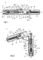
- Figure 1 is a longitudinal section of a reusable auto-injector 1.
- the auto-injector 1 comprises an elongate housing 2.
- a disposable syringe 3, e.g. a Unilife® syringe, with a hollow needle 4 is arranged in a proximal portion of the auto-injector 1.
- a protective needle shield 5 is attached to the needle 4.
- a stopper 6 is arranged for sealing the syringe 3 distally and for displacing a liquid medicament M through the hollow needle 4.
- the syringe 3 is held in a tubular loading bay 7.
- a drive spring 8 in the shape of a compression spring is arranged in a distal portion of the auto-injector 1.
- a plunger 9 is arranged for transmitting the spring force of the drive spring 8.
- the drive spring 8 is used for providing axial motion for advancing the syringe 3, inserting the needle 4 into the injection site, i.e. a patient's skin and injecting a dose of medicament M.
- the needle 4 is withdrawn into the syringe 3 once fully emptied.
- a post-injection needle safety function may be alternatively integrated into the auto-injector 1 instead of the syringe 3.
- the elongate housing 2 comprises an essentially tubular distal portion 2.1 and an essentially tubular proximal portion 2.2 connected by a hinge 10 so the portions 2.1, 2.2 may be operated similar to a break barrel air rifle.
- Figure 2 shows how the disposable syringe is loaded into the auto-injector 1.
- the housing 2 is breached around the hinge 10 so the portions 2.1, 2.2 are not aligned any more.
- the syringe 3 may now be inserted into the loading bay 7 through the distal opening of the proximal portion 2.2.
- a lever 11 is attached with one end to a fixed first pivot 12 in the proximal portion 2.2 of the housing 2.
- the other end of the lever 11 is attached to a second pivot 13 arranged at a sliding shuttle 14 in the distal portion 2.1, the sliding shuttle 14 moveable in longitudinal direction.
- the user closes the auto-injector 1 by rotating the distal portion 2.1 about the hinge 10 until its longitudinal axis is aligned to the longitudinal axis of the proximal portion 2.2 as shown in figure 3 .
- the sliding shuttle 14 translates in proximal direction P within the distal portion 2.1.
- a locking mechanism (not illustrated) may be provided for locking the two portions 2.1, 2.2 in a coaxial position.
- An example mechanism may comprise a cylindrical sleeve mounted around the external surface of the housing 2 constrained to translate along the longitudinal axis.
- the sleeve may be positioned across the joint between the distal portion 2.1 and the proximal portion 2.2 thereby preventing rotation about the hinge 10.
- the sleeve may be sprung loaded such that it automatically locks the portions 2.1, 2.2 coaxially upon aligning them.
- the auto-injector 1 is shown during removal of a cap 17 which had been attached to a proximal end P of the proximal portion 2.2.
- Barbs 17.1 on the cap (see fig. 5a, b ) constrained from moving outward by a detector sleeve 18 slidably arranged at the proximal end P inside the proximal portion 2.2 grip the protective needle shield 5 thus removing the protective needle shield 5 with the cap 17.
- the barbs 17.1 are no longer constrained so the protective needle shield 5 is released and may be easily removed from the cap 5 (see fig. 5c ).
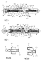
- Figures 6, 7 and 8 show details of an interlock mechanism for defining a sequence of operation of the auto-injector 1.
- the user places the proximal end of the auto-injector 1 against an injection site, i.e. the user's skin. This causes the detector sleeve 18 to translate in distal direction against the bias of a detector spring 19 (see fig. 6 ). As the detector sleeve 17 translates, first latch features and second latch features are released. The first and second latch features prevent the user from accidentally actuating the auto-injector 1 when it is not in contact with the injection site and during a loading and cocking step.
- the first latch features comprise a syringe latch arm 20 transversally pivoted about halfway between its ends, the distal end having a nose 20.1 for engaging behind a shoulder 7.1 arranged at the loading bay 7 in a manner to prevent the loading bay 7 from being moved in proximal direction P (see fig. 7 for details).
- the proximal end of the syringe latch arm 20 comprises a ramp 20.2.
- the detector sleeve 18 comprises a longitudinal extension bar 18.1 extending at least almost to the distal end of the proximal portion 2.2 when the detector sleeve 18 is pushed into the auto-injector 1 and essentially on a level with the proximal end P.
- a dog 18.2 protrudes inwardly from the extension bar 18.1 in a manner to engage the ramp 20.2 when the detector sleeve 18 is pushed into the auto-injector 1, thereby pushing the proximal end of the syringe latch arm 20 inwardly and the distal end of the syringe latch arm 20 outwardly so the nose 20.1 is disengaged from the shoulder 7.1.
- the loading bay 7 is no longer constrained from being moved in proximal direction P.
- a spring may be arranged for keeping the nose 20.1 engaged with the shoulder 7.1 in this situation (not illustrated).
- the latch arm 20 may have a straight end instead of the ramp in which case a ramp may be provided at the dog 18.2.
- both the latch arm 20 and the dog 18.2 may have ramps.
- the second latch features are part of a transmission bar 21 arranged in the distal portion 2.1 and slidable in longitudinal direction.
- a proximal end of the transmission bar 21 bears against a distal end of the extension bar 18.1.
- the transmission bar 21 may be biased by a spring in proximal direction (not illustrated).
- a recess 21.1 is provided for engaging a dog 16.2 arranged at the trigger button 16 (see fig. 8 for details).
- the transmission bar 21 is in a proximal position thus engaging the dog 16.2 in a manner to prevent the trigger button 16 from being pushed inwardly at its proximal end.
- the distal end of the trigger button 16 is pivoted in the distal portion 2.1.
- the user depresses the trigger button 16.
- the snap arms 15.1, 16.1 disengage thus releasing the drive collar 15 and allowing the drive spring 8 to extend.
- the force from the drive spring 8 is transferred through the drive collar 15 and a release latch member 22 to the plunger 9.
- the friction between the stopper 6 and the inner wall of the syringe 3 opposes relative motion between them. This friction is greater than a sum of the force of a syringe retraction spring 23 arranged between the shoulder 7.1 of the loading bay 7 and a protrusion 24 in the proximal portion 2.2 and a needle insertion force between the needle 4 and the patient's skin.
- the needle 4 is inserted into the user's skin without medicament leaking out of the needle's tip (wet injection).
- An insertion depth is controlled by a flange or shoulder 7.1 of loading bay 7 contacting a stop 25 arranged in the proximal portion 2.2 (see figs. 10 and 11 ).
- the stop 25 or the two stops 25 may be arranged at a proximal end of a respective longitudinal rib 25.1 arranged in the proximal portion 2.2.
- the loading bay flange 7.1 may have recesses for rotationally fixing the loading bay flange 7.1 by the longitudinal ribs 25.1.
- the drive collar 15 is coupled to the release latch member 22 through a spring and damper unit 26 comprising a plunger spring 26.1 in parallel with a viscous damper 26.2.
- a coefficient of damping of the viscous damper 26.2 is specified such that a time taken to fully compress the plunger spring 26.1 is greater than a time required to fully empty the syringe 3. This means the stopper 6 will always fully empty the syringe 3.
- the viscous damper 26.2 comprises a piston 26.2.1 fixed to the drive collar 15 by a connecting rod 26.2.2, the piston 26.2.1 having a greater diameter than the connecting rod 26.2.2.
- a hollow cylinder 26.2.3 with an internal diameter slightly greater than the diameter of the piston 26.2.1 is arranged around the piston 26.2.1 so the piston 26.1.1 and cylinder 26.2.3 may reciprocate.
- a proximal end face of the cylinder 26.2.3 is fully closed.
- a distal end face is arranged to seal the cylinder 26.2.3 against the connecting rod 26.2.2.
- a small transfer port 26.2.4 is provided through the piston 26.2.1 in longitudinal direction allowing a fluid to flow from the distal side of the piston 26.2.1 to the proximal side and vice versa.
- Respective gasket rings 26.2.5 and 26.2.6 are arranged to seal the piston 26.2.1 against the cylinder 26.2.3 and the connecting rod 26.2.2 against the hole in the distal end face of the cylinder 26.2.3.
- the piston 26.2.1 and the distal face wall are provided with respective circumferential notches in order to hold the gasket rings 26.2.5, 26.2.6 in place.
- the size of the transfer port 26.2.4 controls the damper characteristics.
- the fluid may be one of air, another gas, a liquid, grease, e.g. silicone grease. If an incompressible fluid, such as a liquid is used, an air pocket may be provided in the cylinder 26.2.3 in order to compensate for the disparity in volume change at the proximal and the distal side of the piston 26.2.1 during translation.
- the plunger spring 26.1 is arranged in a longitudinal bore in the connecting rod 26.2.2 and grounded at its distal end in the drive collar 15.
- the proximal end of the plunger spring 26.1 bears against the proximal face of the cylinder 26.2.3 from inside.
- the cylinder 26.2.3 may be translated towards the drive collar 15 against the force of the plunger spring 26.1 and the plunger spring 26.1 may push the cylinder 26.2.3. away from the drive collar 15.
- the release latch member 22 is distally pivoted in the spring and damper unit 26, particularly in the cylinder 26.2.3.
- a ramp 15.2 on the drive collar 15 contacts a ramp 22.1 on the release latch member 22 thus rotating the release latch member 22 outward and consequently decoupling the drive spring 8 from the plunger 9 (see figs. 14 and 16 ).
- the needle 4 is withdrawn inside the syringe 3. This may be achieved by the stopper 6 gripping the distal end of the needle 4.
- the stopper 6 may be pulled in distal direction by means of a spring arranged inside the syringe 3 (not illustrated in the figures). The needle 4 is thus pulled into the syringe 3 and the plunger 9 pushed out in distal direction D into the gap vacated by the latch member.
- the spring and damper unit 26 may now return to its initial state under the force of the plunger spring 26.1.
- the detector sleeve 18 is pushed in proximal direction P of the proximal portion 2.2 under load of the compressed detector spring 19.
- the detector spring 19 may be grounded in the protrusion 24.
- the auto-injector 1 would also work with a fixed needle syringe, such as a Hypak syringe as well.
Abstract
The invention relates to an interlock mechanism for defining an operation sequence of an auto-injector (1) in a manner to allow a lateral trigger button (16) to be operated only when a proximal end (P) of the auto-injector (1) is pressed against an injection site, wherein a detector means (18) is arranged inside an elongate housing (2) of the auto-injector (1) at the proximal end (P), the detector means (18) slidable in longitudinal direction and biased by a detector spring (19) into a position with the detector means (18) protruding beyond the proximal end (P), wherein a dog (16.2) is arranged at the trigger button (16) and wherein at least one longitudinal bar (18.1, 21) is provided, at least one of the bars (21) slidable in longitudinal direction and coupled to the detector means (18) for joint movement at least in distal direction (D), wherein a recess (21.1) for the dog (16.2) is provided in the bar (21) for allowing the trigger button (16) to be pressed when the detector means (18) is being pushed into the auto-injector (1) and wherein otherwise the dog (16.2) is engaged with the bar (21) in a manner to prevent the trigger button (16) from being pressed.
Description
- The invention relates to an interlock mechanism for defining an operation sequence of an auto-injector for administering a dose of a liquid medicament.
- Administering an injection is a process which presents a number of risks and challenges for users and healthcare professionals, both mental and physical.
- Injection devices (i.e. devices capable of delivering medicaments from a medication container) typically fall into two categories ― manual devices and auto-injectors.
- In a manual device - the user must provide the mechanical energy to drive the fluid through the needle. This is typically done by some form of button / plunger that has to be continuously pressed by the user during the injection. There are numerous disadvantages to the user from this approach. If the user stops pressing the button /plunger then the injection will also stop. This means that the user can deliver an underdose if the device is not used properly (i.e. the plunger is not fully pressed to its end position). Injection forces may be too high for the user, in particular if the patient is elderly or has dexterity problems.
- The extension of the button/plunger may be too great. Thus it can be inconvenient for the user to reach a fully extended button. The combination of injection force and button extension can cause trembling / shaking of the hand which in turn increases discomfort as the inserted needle moves.
- Auto-injector devices aim to make self-administration of injected therapies easier for patients. Current therapies delivered by means of self-administered injections include drugs for diabetes (both insulin and newer GLP-1 class drugs), migraine, hormone therapies, anticoagulants etc.
- Auto-injectors are devices which completely or partially replace activities involved in parenteral drug delivery from standard syringes. These activities may include removal of a protective syringe cap, insertion of a needle into a patient's skin, injection of the medicament, removal of the needle, shielding of the needle and preventing reuse of the device. This overcomes many of the disadvantages of manual devices. Forces required of the user / button extension, hand-shaking and the likelihood of delivering an incomplete dose are reduced. Triggering may be performed by numerous means, for example a trigger button, the action of placing the autoinjector against the skin, or the action of the needle reaching its injection depth. In some devices the energy to deliver the fluid is provided by a spring.
- Auto-injectors may be disposable or single use devices which may only be used to deliver one dose of medicament and which have to be disposed of after use. Other types of auto-injectors may be reusable. Usually they are arranged to allow a user to load and unload a standard syringe. The reusable auto-injector may be used to perform multiple parenteral drug deliveries, whereas the syringe is disposed after having been spent and unloaded from the auto-injector. The syringe may be packaged with additional parts to provide additional functionality.
-
US 2002/0095120 A1 discloses an automatic injection device which automatically injects a pre-measured quantity of fluid medicine when a tension spring is released. The tension spring moves an ampoule and the injection needle from a storage position to a deployed position when it is released. The content of the ampoule is thereafter expelled by the tension spring forcing a piston forward inside the ampoule. After the fluid medicine has been injected, energy stored in the tension spring is released and the injection needle is automatically retracted back to its original storage position. - In order to prevent needle stick injuries due to inadvertently operated auto-injectors it is desirable to prevent the trigger button from being pressed as long as the auto-injector is not properly positioned against an injection site, i.e. a user's skin.
- It is therefore an object of the present invention to provide a novel interlock mechanism for defining an operation sequence of an auto-injector.
- The object is achieved by an interlock mechanism according to
claim 1. - Preferred embodiments of the invention are given in the dependent claims.
- According to the invention an interlock mechanism serves for defining an operation sequence of an auto-injector in a manner to allow a trigger button to be operated only when a proximal end of the auto-injector is pressed against an injection site.
- A detector means is arranged inside an elongate housing of the auto-injector at the proximal end. The detector means is slidable in longitudinal direction and biased by a detector spring into a position with the detector means protruding beyond the proximal end. A dog is arranged at the trigger button. At least one longitudinal bar is provided in the housing. At least one of the bars is slidable in longitudinal direction and coupled to the detector means for joint movement at least in distal direction. A recess for the dog is provided in the bar for allowing the trigger button to be pressed when the detector means is being pushed into the auto-injector. Otherwise the dog is engaged with the bar in a manner to prevent the trigger button from being pressed.
- The interlock mechanism according to the invention is arranged to prevent the trigger button from being pressed as long as the auto-injector is not pressed against the injection site in order to keep the user from activating the auto-injector inadvertently. This increases needle safety and reduces the risk for needle stick injuries and for wasting the medicament without injecting it. The interlock mechanism is arranged to be disengaged by the proximal end of the auto-injector being pressed against the injection site. This skin interlock feature ensures that the device can only be triggered when it is properly positioned for an injection.
- The interlock mechanism may be disengaged by pressing the detector means against the injection site. Thus the detector means is translated against the force of the detector spring in distal direction. The interlock mechanism may be arranged to disengage when the detector means is pushed into the auto-injector and essentially on a level with the proximal end of the auto-injector. However, the interlock mechanism may also be arranged to disengage when the detector means is pushed in and still protruding from the proximal end to a lesser extent than without being pushed.
- The trigger button is preferably laterally arranged. However, the trigger button may likewise be arranged at a distal end or in another position.
- In a preferred embodiment at least one of the bars may comprise a protruding dog, e.g. protruding inwardly from the bar. A loading bay for a syringe may be arranged slidable in longitudinal direction in a manner to advance or retract the syringe. A syringe latch arm having a distal end and a proximal end may be pivoted about a latch arm axis transversally arranged to and offset from a longitudinal axis of the auto-injector. The distal end of the latch arm may be arranged for engaging behind a shoulder arranged at the loading bay in a manner to prevent the loading bay from being moved in proximal direction. The proximal end of the latch arm may be arranged for being engaged by the dog when the detector means is pushed into the auto-injector thus disengaging the distal end of the latch arm from the shoulder.
- Once the latch arm is disengaged from the shoulder, the loading bay with the syringe is allowed to be moved in proximal direction. When the detector means is not pushed into the auto-injector, the syringe latch arm prevents the syringe from being advanced.
- The detector means may be arranged as an essentially tubular detector sleeve or as a part with at least one tooth protruding beyond the proximal end.
- The proximal end of the latch arm and/or the dog for engaging it may comprise a ramp for easing their interaction.
- In a preferred embodiment at least one of the bars is arranged as an extension bar attached to the detector means and extending at least almost to a distal end of a proximal portion of the housing when the detector sleeve is pushed into the auto-injector. This extension bar serves for operating the latch arm. Another one of the bars may be arranged in a distal portion of the housing as a transmission bar serving for interacting with the trigger button.
- A proximal end of the transmission bar may bear against a distal end of the extension bar when the portions are aligned. Consequently, translation of the detector sleeve is forwarded to the transmission bar when the portions are aligned. This allows for employing the interlock mechanism in reusable auto-injectors comprising housing portions which can be separated for replacing the syringe in the loading bay.
- Such a reusable auto-injector for administering a dose of a liquid medicament may comprise:
- the elongate housing arranged to contain the syringe with a hollow needle and a stopper for sealing the syringe and displacing the medicament, the housing having a distal end and a proximal end with an orifice intended to be applied against the injection site, wherein the syringe is slidably arranged with respect to the housing,
- a drive spring capable of, upon activation:
- pushing the needle from a covered position inside the housing into an advanced position through the orifice and past the proximal end, and
- operating the syringe to supply the dose of medicament, and
- activating means, i.e. the trigger button arranged to lock the drive spring in a compressed state prior to manual operation and capable of, upon manual operation, releasing the drive spring for injection.
- The elongate housing may comprise the distal portion and the proximal portion connected by a hinge, the hinge having a rotational axis offset from a longitudinal axis of the auto-injector and oriented transversally with respect to the longitudinal axis. The portions are rotatable about the hinge relative to each other between an aligned position with their longitudinal axes aligned and a maximum opening angle. The drive spring may be compressed by rotating the portions out of the aligned position towards the maximum opening angle. The activating means are arranged to lock the drive spring in the compressed state when the portions are rotated at least almost by the maximum opening angle. The loading bay for holding the syringe is arranged in the proximal portion, the loading bay accessible from its distal end for loading or unloading the syringe when the portions are rotated out of the aligned position, e.g. when they are rotated by least almost the maximum opening angle.
- An alternative embodiment of the auto-injector with the interlock mechanism may have the two portions connectable by other means than the hinge, e.g. a screw connection, bayonet fit, re-priming plunger or lever.
- In the context of this specification the term proximal refers to the direction pointing towards the patient during an injection while the term distal refers to the opposite direction pointing away from the patient. When referring to the proximal and distal portion of the auto-injector their respective distal and proximal ends are those that point in the respective direction during an injection, i.e. with the portions aligned. In the terminology of this specification the distal end of the distal portion remains the distal end even if the portions are rotated by the maximum opening angle in such a manner that the distal end of the distal portion essentially points in the same direction as the proximal end of the proximal portion in this situation.
- The said auto-injector is a reusable auto-injector, which may be split in two by rotating or 'cocking' the portions about the hinge. On the one hand this rotating action serves for cocking the drive spring, on the other hand it provides access to the loading bay in order to remove a spent syringe and insert a new, unused one. As opposed to conventional reusable auto-injectors, the auto-injector according to the invention involves less user actions to reset it for another drug delivery. Conventional auto-injectors usually require the user to dismantle it after use, load a new syringe, reset the drive spring and reassemble the auto-injector.
- Once the activating means has been operated to release the drive spring the auto-injector will advance the syringe and needle thereby inserting the needle into the injection site, e.g. a patient's skin. Furthermore the auto-injector will automatically empty the syringe in order to deliver the medicament.
- In a preferred embodiment a lever may be attached with one end to a fixed first pivot in the proximal portion, wherein the other end of the lever may be attached to a second pivot arranged at a sliding shuttle in the distal portion. The sliding shuttle may be translatable in longitudinal direction of the distal portion between a maximum proximal position when the portions are aligned and a maximum distal position when the portions are rotated at least almost by the maximum opening angle, which may be about 180 degrees. A drive collar arranged at a proximal end of the drive spring may be engageable by the sliding shuttle in order to compress the drive spring, i.e. the sliding shuttle pushes the drive collar in a distal direction in the distal portion as the portions are rotated out of alignment thus cocking the drive spring, whose distal end may be grounded inside the distal end of the distal portion. During that cocking process, the mechanical advantage increases as the drive spring is compressed due to the lever action. This is particularly advantageous if the drive spring is a compression spring whose spring force increases with the level of compression. Thus, the user effort required to reset the auto-injector is reduced.
- The loading bay is preferably biased in distal direction by a syringe retraction spring. The syringe retraction spring may be a compression spring arranged around the loading bay. It may be arranged to retract the syringe in a manner to hide the needle inside the proximal portion after delivering the dose of medicament by decoupling the plunger from the drive spring. This feature provides post-injection needle safety, i.e. the user is prevented from needle stick injury after removing the auto-injector from the injection site.
- In another preferred embodiment a spring and damper unit and a release latch member may be arranged proximally from the drive collar in a manner to allow transmission of the force of the drive spring to the plunger when the portions are aligned. The spring and damper unit may comprise a plunger spring and a viscous damper in parallel. A coefficient of damping of the viscous damper and a spring constant of the plunger spring are specified to allow the plunger spring to be compressed by the force of the drive spring against a counteracting force of the stopper in a time greater than a time required to fully empty the syringe. The counteracting force of the stopper depends on friction between the stopper and the inner wall of the syringe and on the hydrostatic resistance of the liquid medicament being displaced through the hollow needle. The release latch member may be pivoted in the spring and damper unit and arranged to be rotated out of engagement with the plunger by the drive collar when the plunger spring is fully compressed. Force transmission from the drive spring to the plunger is thus interrupted and the syringe retraction spring may retract the syringe and needle. Thus both problems are solved, reliably retracting the hollow needle to a safe position and fully emptying the syringe which is particularly desirable with expensive drugs. Emptying the syringe is also important for dosage accuracy.
- Preferably, the viscous damper may comprise a piston fixed to the drive collar by a connecting rod, with the piston having a greater diameter than the connecting rod. A hollow cylinder, with an internal diameter slightly greater than the diameter of the piston, may be arranged around the piston thus allowing the piston and cylinder to reciprocate. A proximal end face of the cylinder may be fully closed and a distal end face of the cylinder may be arranged to seal the cylinder against the connecting rod. Thus, the interior of the cylinder may be divided into two separate cavities by the piston. At least one transfer port may be provided through the piston in a manner to allow a fluid to flow between the distal side of the piston and the proximal side, i.e. from one cavity into the other. The size and number of the transfer ports and the viscosity of the fluid in the cylinder determine the damping characteristics of the viscous damper.
- A gasket ring may be arranged to seal the piston against the cylinder in order to avoid uncontrolled leaking of the fluid between the cavities which might lead to less repeatable damping characteristics.
- Another gasket ring may be arranged to seal the connecting rod against the distal end face of the cylinder in order to avoid fluid leaking out of the damper which would otherwise in a drift of the damping characteristics due to disappearing liquid and to pollution of the interior of the auto-injector. An air space may be provided in the cylinder, e.g. by only partially filling it with the damping fluid in order to compensate for the volume of the connecting rod as it goes into the cylinder. Otherwise the viscous damper could lock since the volume of fluid displaced by the piston on its proximal side is greater than the volume increase on the distal side due to the volume of the connecting rod. Air or another gas provided in the cylinder in addition to the viscous fluid can be compressed in order to compensate this disparity in volume change. A hydraulic lock situation is thus avoided.
- The plunger spring may be arranged in a longitudinal bore in the connecting rod and grounded at its distal end in the drive collar. The proximal end of the plunger spring may bear against the proximal face of the cylinder from inside. Thus, the spring and damper unit is arranged as a compact unit.
- The drive collar and the trigger button may be equipped with respective snap arms arranged to snap into each other when the drive spring is sufficiently compressed. The snap arms may be disengaged by pressing the trigger button.
- Usually the hollow needle is equipped with a protective needle shield for keeping the needle sterile and preventing it from being mechanically damaged. The protective needle shield is attached to the needle when the syringe is assembled.
- In order to prepare the auto-injector for delivering a dose the protective needle shield has to be removed from the needle.
- In one embodiment of the invention a cap may be arrangeable at the proximal end of the proximal portion. In the cap barbs may be provided for gripping the protective needle shield. When the cap is removed from the housing in preparation of an injection the protective needle shield is reliably removed without exposing the user to too high a risk to injure themselves.
- The barbs may be arranged to snap into a circumferential notch or behind a shoulder of the protective needle shield.
- Preferably the barbs are arranged to be constrained by the detector sleeve from moving radially outward and inadvertently disengaging the protective needle cap as long as the cap is arranged at the auto-injector.
- The cap may be attachable to the housing by a screw connection. This allows for a low force removal of the protective needle shield.
- The housing may have at least one viewing window for inspecting the syringe, or be manufactured from a transparent material.
- The auto-injector may preferably be used for subcutaneous or intra-muscular injection, particularly for delivering one of an analgesic, an anticoagulant, insulin, an insulin derivate, heparin, Lovenox, a vaccine, a growth hormone, a peptide hormone, a protein, antibodies and complex carbohydrates.
- Further scope of applicability of the present invention will become apparent from the detailed description given hereinafter. However, it should be understood that the detailed description and specific examples, while indicating preferred embodiments of the invention, are given by way of illustration only, since various changes and modifications within the spirit and scope of the invention will become apparent to those skilled in the art from this detailed description.
- The present invention will become more fully understood from the detailed description given hereinbelow and the accompanying drawings which are given by way of illustration only, and thus, are not limitive of the present invention, and wherein:
- Figure 1
- is a longitudinal section of a reusable auto-injector,
- Figure 2
- is a longitudinal section of the auto-injector during loading of a syringe,
- Figure 3
- is the auto-injector in a resetting step after loading,
- Figure 4
- is the auto-injector during removal of a cap and a rigid needle shield,
- Figure 5
- shows the cap and rigid needle shield in different stages of operation,
- Figure 6
- is the auto-injector pressed against an injection site after the cap and rigid needle shields have been removed,
- Figure 7
- is a perspective detail view of a syringe interlock with a protective sleeve,
- Figure 8
- is a perspective detail view of a trigger button interlock with the protective sleeve,
- Figure 9
- is the auto-injector during actuation by means of the trigger button,
- Figure 10
- is a perspective detail view of a loading bay,
- Figure 11
- is another perspective detail view of the loading bay,
- Figure 12
- is the auto-injector near the end of an injection stroke,
- Figure 13
- is a detail view of a damped delay member near the end of the injection stroke,
- Figure 14
- is a detail view of the damped delay member decoupled from the syringe after the end of the injection,
- Figure 15
- is a perspective view of the damped delay member of
figure 13 , - Figure 16
- is a perspective view of the damped delay member of
figure 14 , - Figure 17
- is the auto-injector when being removed from the injection site, and
- Figure 18
- is the auto-injector during removal of the spent syringe.
- Corresponding parts are marked with the same reference symbols in all figures.
-
Figure 1 is a longitudinal section of a reusable auto-injector 1. The auto-injector 1 comprises an elongate housing 2. Adisposable syringe 3, e.g. a Unilife® syringe, with ahollow needle 4 is arranged in a proximal portion of the auto-injector 1. When thesyringe 3 is assembled aprotective needle shield 5 is attached to theneedle 4. Astopper 6 is arranged for sealing thesyringe 3 distally and for displacing a liquid medicament M through thehollow needle 4. Thesyringe 3 is held in atubular loading bay 7. Adrive spring 8 in the shape of a compression spring is arranged in a distal portion of the auto-injector 1. Aplunger 9 is arranged for transmitting the spring force of thedrive spring 8. Thedrive spring 8 is used for providing axial motion for advancing thesyringe 3, inserting theneedle 4 into the injection site, i.e. a patient's skin and injecting a dose of medicament M. - In the present embodiment the
needle 4 is withdrawn into thesyringe 3 once fully emptied. However, a post-injection needle safety function may be alternatively integrated into the auto-injector 1 instead of thesyringe 3. - The elongate housing 2 comprises an essentially tubular distal portion 2.1 and an essentially tubular proximal portion 2.2 connected by a
hinge 10 so the portions 2.1, 2.2 may be operated similar to a break barrel air rifle. -
Figure 2 shows how the disposable syringe is loaded into the auto-injector 1. The housing 2 is breached around thehinge 10 so the portions 2.1, 2.2 are not aligned any more. Thesyringe 3 may now be inserted into theloading bay 7 through the distal opening of the proximal portion 2.2. Alever 11 is attached with one end to a fixedfirst pivot 12 in the proximal portion 2.2 of the housing 2. The other end of thelever 11 is attached to asecond pivot 13 arranged at a slidingshuttle 14 in the distal portion 2.1, the slidingshuttle 14 moveable in longitudinal direction. When the portions 2.1, 2.2 are aligned as infigure 1 the slidingshuttle 14 is held in a maximum proximal position by thelever 11. When the housing 2 is breached around the hinge as infigure 2 thelever 11 forces the slidingshuttle 14 to move in distal direction D as shown infigure 2 . Infigure 2 thedrive spring 8 is already in a compressed state. However, if the auto-injector 1 is breached open following an injection the then relaxeddrive spring 8 is cocked by thelever 11 since the slidingshuttle 14 bears against adrive collar 15 arranged at a proximal end of the drive spring 8 (cf.fig. 18 ). When the slidingshuttle 14 has pushed thedrive collar 15 to a maximum distal position a snap arm 15.1 of the drive collar snaps behind a snap arm 16.1. of atrigger button 16. This lever action resets the auto-injector 1 for another injection cycle. - After cocking the drive spring and inserting the
syringe 3 in the manner described the user closes the auto-injector 1 by rotating the distal portion 2.1 about thehinge 10 until its longitudinal axis is aligned to the longitudinal axis of the proximal portion 2.2 as shown infigure 3 . As the auto-injector 1 is closed, the slidingshuttle 14 translates in proximal direction P within the distal portion 2.1. A locking mechanism (not illustrated) may be provided for locking the two portions 2.1, 2.2 in a coaxial position. An example mechanism may comprise a cylindrical sleeve mounted around the external surface of the housing 2 constrained to translate along the longitudinal axis. To lock the auto-injector 1, once thesyringe 3 had been loaded, the sleeve may be positioned across the joint between the distal portion 2.1 and the proximal portion 2.2 thereby preventing rotation about thehinge 10. The sleeve may be sprung loaded such that it automatically locks the portions 2.1, 2.2 coaxially upon aligning them. - In
figure 4 the auto-injector 1 is shown during removal of acap 17 which had been attached to a proximal end P of the proximal portion 2.2. Barbs 17.1 on the cap (seefig. 5a, b ) constrained from moving outward by adetector sleeve 18 slidably arranged at the proximal end P inside the proximal portion 2.2 grip theprotective needle shield 5 thus removing theprotective needle shield 5 with thecap 17. Once thecap 17 is removed, the barbs 17.1 are no longer constrained so theprotective needle shield 5 is released and may be easily removed from the cap 5 (seefig. 5c ). -
Figures 6, 7 and8 show details of an interlock mechanism for defining a sequence of operation of the auto-injector 1. - Following the removal of the
cap 17 the user places the proximal end of the auto-injector 1 against an injection site, i.e. the user's skin. This causes thedetector sleeve 18 to translate in distal direction against the bias of a detector spring 19 (seefig. 6 ). As thedetector sleeve 17 translates, first latch features and second latch features are released. The first and second latch features prevent the user from accidentally actuating the auto-injector 1 when it is not in contact with the injection site and during a loading and cocking step. - The first latch features comprise a
syringe latch arm 20 transversally pivoted about halfway between its ends, the distal end having a nose 20.1 for engaging behind a shoulder 7.1 arranged at theloading bay 7 in a manner to prevent theloading bay 7 from being moved in proximal direction P (seefig. 7 for details). The proximal end of thesyringe latch arm 20 comprises a ramp 20.2. Thedetector sleeve 18 comprises a longitudinal extension bar 18.1 extending at least almost to the distal end of the proximal portion 2.2 when thedetector sleeve 18 is pushed into the auto-injector 1 and essentially on a level with the proximal end P. A dog 18.2 protrudes inwardly from the extension bar 18.1 in a manner to engage the ramp 20.2 when thedetector sleeve 18 is pushed into the auto-injector 1, thereby pushing the proximal end of thesyringe latch arm 20 inwardly and the distal end of thesyringe latch arm 20 outwardly so the nose 20.1 is disengaged from the shoulder 7.1. Thus theloading bay 7 is no longer constrained from being moved in proximal direction P. As long as thedetector sleeve 18 is not pushed back the dog 18.2 does not interact with the ramp 20.2. A spring may be arranged for keeping the nose 20.1 engaged with the shoulder 7.1 in this situation (not illustrated). - In another embodiment the
latch arm 20 may have a straight end instead of the ramp in which case a ramp may be provided at the dog 18.2. In yet another embodiment both thelatch arm 20 and the dog 18.2 may have ramps. - The second latch features are part of a
transmission bar 21 arranged in the distal portion 2.1 and slidable in longitudinal direction. When the portions 2.1, 2.2 are coaxially aligned a proximal end of thetransmission bar 21 bears against a distal end of the extension bar 18.1. For this purpose thetransmission bar 21 may be biased by a spring in proximal direction (not illustrated). Near a distal end of the transmission bar 21 a recess 21.1 is provided for engaging a dog 16.2 arranged at the trigger button 16 (seefig. 8 for details). Before thedetector sleeve 18 is pushed into the auto-injector 1 (cf.fig. 1 ) thetransmission bar 21 is in a proximal position thus engaging the dog 16.2 in a manner to prevent thetrigger button 16 from being pushed inwardly at its proximal end. The distal end of thetrigger button 16 is pivoted in the distal portion 2.1. When thedetector sleeve 18 is pushed into the auto-injector 1 the translation is forwarded by the extension bar 18.1 to thetransmission bar 21 so the dog 16.2 of thetrigger button 16 finds some clearance in the recess 21.1 thus allowing the proximal end of thetrigger button 16 to be pushed inward. - In order to deliver an injection the user depresses the
trigger button 16. As the proximal end of thetrigger button 16 moves inward the snap arms 15.1, 16.1 disengage thus releasing thedrive collar 15 and allowing thedrive spring 8 to extend. The force from thedrive spring 8 is transferred through thedrive collar 15 and arelease latch member 22 to theplunger 9. The friction between thestopper 6 and the inner wall of thesyringe 3 opposes relative motion between them. This friction is greater than a sum of the force of asyringe retraction spring 23 arranged between the shoulder 7.1 of theloading bay 7 and aprotrusion 24 in the proximal portion 2.2 and a needle insertion force between theneedle 4 and the patient's skin. Hence theneedle 4 is inserted into the user's skin without medicament leaking out of the needle's tip (wet injection). An insertion depth is controlled by a flange or shoulder 7.1 ofloading bay 7 contacting astop 25 arranged in the proximal portion 2.2 (seefigs. 10 and11 ). Thestop 25 or the two stops 25 may be arranged at a proximal end of a respective longitudinal rib 25.1 arranged in the proximal portion 2.2. The loading bay flange 7.1 may have recesses for rotationally fixing the loading bay flange 7.1 by the longitudinal ribs 25.1. - Once the finger flange 3.1 contacts the
stops 25, the force of thedrive spring 8 acting on thestopper 6 is sufficient to overcome friction so the emptying of the syringe contents commences. - The
drive collar 15 is coupled to therelease latch member 22 through a spring anddamper unit 26 comprising a plunger spring 26.1 in parallel with a viscous damper 26.2. A coefficient of damping of the viscous damper 26.2 is specified such that a time taken to fully compress the plunger spring 26.1 is greater than a time required to fully empty thesyringe 3. This means thestopper 6 will always fully empty thesyringe 3. - In the
figures 15 and16 the spring anddamper unit 26 is shown in detail. The viscous damper 26.2 comprises a piston 26.2.1 fixed to thedrive collar 15 by a connecting rod 26.2.2, the piston 26.2.1 having a greater diameter than the connecting rod 26.2.2. A hollow cylinder 26.2.3 with an internal diameter slightly greater than the diameter of the piston 26.2.1 is arranged around the piston 26.2.1 so the piston 26.1.1 and cylinder 26.2.3 may reciprocate. A proximal end face of the cylinder 26.2.3 is fully closed. A distal end face is arranged to seal the cylinder 26.2.3 against the connecting rod 26.2.2. A small transfer port 26.2.4 is provided through the piston 26.2.1 in longitudinal direction allowing a fluid to flow from the distal side of the piston 26.2.1 to the proximal side and vice versa. Respective gasket rings 26.2.5 and 26.2.6 are arranged to seal the piston 26.2.1 against the cylinder 26.2.3 and the connecting rod 26.2.2 against the hole in the distal end face of the cylinder 26.2.3. The piston 26.2.1 and the distal face wall are provided with respective circumferential notches in order to hold the gasket rings 26.2.5, 26.2.6 in place. There may be more than one transfer port 26.2.4 through the piston 26.2.1. The size of the transfer port 26.2.4 controls the damper characteristics. The fluid may be one of air, another gas, a liquid, grease, e.g. silicone grease. If an incompressible fluid, such as a liquid is used, an air pocket may be provided in the cylinder 26.2.3 in order to compensate for the disparity in volume change at the proximal and the distal side of the piston 26.2.1 during translation. - The plunger spring 26.1 is arranged in a longitudinal bore in the connecting rod 26.2.2 and grounded at its distal end in the
drive collar 15. The proximal end of the plunger spring 26.1 bears against the proximal face of the cylinder 26.2.3 from inside. Hence the cylinder 26.2.3 may be translated towards thedrive collar 15 against the force of the plunger spring 26.1 and the plunger spring 26.1 may push the cylinder 26.2.3. away from thedrive collar 15. - The
release latch member 22 is distally pivoted in the spring anddamper unit 26, particularly in the cylinder 26.2.3. - Once the
syringe 3 is fully emptied and the plunger spring 26.1 is fully compressed, a ramp 15.2 on thedrive collar 15 contacts a ramp 22.1 on therelease latch member 22 thus rotating therelease latch member 22 outward and consequently decoupling thedrive spring 8 from the plunger 9 (seefigs. 14 and16 ).Theneedle 4 is withdrawn inside thesyringe 3. This may be achieved by thestopper 6 gripping the distal end of theneedle 4. Thestopper 6 may be pulled in distal direction by means of a spring arranged inside the syringe 3 (not illustrated in the figures). Theneedle 4 is thus pulled into thesyringe 3 and theplunger 9 pushed out in distal direction D into the gap vacated by the latch member. In order to enable both the withdrawal of theneedle 4 and thesyringe 3 sufficient space has to be provided for the distal end of theplunger 9 towards the spring anddamper unit 26. This is achieved by appropriately selecting the length of therelease latch member 22. Due to the interrupted force propagation the plunger spring 26.1 will now return the cylinder 26.2.3 to its initial position for further injections as shown infigures 12 and15 . - The lever action described above is reversed, i.e. the distal portion 2.1 is rotated about the
hinge 10 with respect to the proximal portion 2.2 thus allowing access to the loading bay 7 (seefig. 18 ). As the auto-injector 1 is hinged in two, thelever 11 translates the slidingshuttle 14 in distal direction of the distal portion 2.1. The slidingshuttle 14 contacts thedrive collar 15 and compresses thedrive spring 8 in preparation for further injections. - Upon full opening, the snap arms 15.1 and 16.1 of the
drive collar 15 and thetrigger button 16 snap into each other thus preventing thedrive spring 8 from expanding. The emptiedsyringe 3 may now be safely removed from theloading bay 7. - The spring and
damper unit 26 may now return to its initial state under the force of the plunger spring 26.1. - The
detector sleeve 18 is pushed in proximal direction P of the proximal portion 2.2 under load of thecompressed detector spring 19. Thedetector spring 19 may be grounded in theprotrusion 24. - Although the figures illustrate a
syringe 3 with a retracting needle, which ensures needle safety at all times even when changing the disposable syringe, the auto-injector 1 would also work with a fixed needle syringe, such as a Hypak syringe as well. -
- 1
- auto-injector
- 2
- elongate housing
- 2.1
- distal portion
- 2.2
- proximal portion
- 3
- syringe
- 3.1
- finger flange
- 4
- hollow needle
- 5
- protective needle shield
- 6
- stopper
- 7
- loading bay
- 7.1
- shoulder, flange
- 8
- drive spring
- 9
- plunger
- 10
- hinge
- 11
- lever
- 12
- first pivot
- 13
- second pivot
- 14
- sliding shuttle
- 15
- drive collar
- 15.1
- snap arm
- 15.2
- ramp
- 16
- trigger button
- 16.1
- snap arm
- 16.2
- dog
- 17
- cap
- 17.1
- barbs
- 18
- detector sleeve
- 18.1
- extension bar
- 18.2
- dog
- 19
- detector spring
- 20
- syringe latch arm
- 20.1
- nose
- 20.2
- ramp
- 21
- transmission bar
- 21.1
- recess
- 22
- release latch member
- 22.1
- ramp
- 23
- syringe retraction spring
- 24
- protrusion
- 25
- stop
- 25.1
- longitudinal rib
- 26
- spring and damper unit
- 26.1
- plunger spring
- 26.2
- viscous damper
- 26.2.1
- piston
- 26.2.2
- connecting rod
- 26.2.3
- hollow cylinder
- 26.2.4
- transfer port
- 26.2.5
- gasket ring
- 26.2.6
- gasket ring
- D
- distal end, distal direction
- M
- medicament
- P
- proximal end, proximal direction
Claims (15)
- Interlock mechanism for defining an operation sequence of an auto-injector (1) in a manner to allow a trigger button (16) to be operated only when a proximal end (P) of the auto-injector (1) is pressed against an injection site, wherein a detector means (18) is arranged inside an elongate housing (2) of the auto-injector (1) at the proximal end (P), the detector means (18) slidable in longitudinal direction and biased by a detector spring (19) into a position with the detector means (18) protruding beyond the proximal end (P), wherein a dog (16.2) is arranged at the trigger button (16) and wherein at least one longitudinal bar (18.1, 21) is provided, at least one of the bars (21) slidable in longitudinal direction and coupled to the detector means (18) for joint movement at least in distal direction (D), wherein a recess (21.1) for the dog (16.2) is provided in the bar (21) for allowing the trigger button (16) to be pressed when the detector means (18) is being pushed into the auto-injector (1) and wherein otherwise the dog (16.2) is engaged with the bar (21) in a manner to prevent the trigger button (16) from being pressed.
- Interlock mechanism according to claim 1, characterized in that at least one of the bars (18.1) comprises a dog (18.2) protruding from the bar (18.1), wherein a loading bay (7) is arranged slidable in longitudinal direction in a manner to advance or retract the syringe (3), wherein a syringe latch arm (20) having a distal end and a proximal end is pivoted about a latch arm axis transversally arranged to and offset from a longitudinal axis of the auto-injector (1), wherein the distal end of the latch arm (20) is arranged for engaging behind a shoulder (7.1) arranged at the loading bay (7) in a manner to prevent the loading bay (7) from being moved in proximal direction (P) and wherein the proximal end of the latch arm (20) is arranged for being engaged by the dog (18.2) when the detector means (18) is pushed into the auto-injector (1) thus disengaging the distal end of the latch arm (20) from the shoulder (7.1).
- Interlock mechanism according to one of the claims 1 or 2, characterized in that the detector means (18) is arranged as a detector sleeve (18).
- Interlock mechanism according to one of the preceding claims, characterized in that the dog (18.2) and/or the proximal end of the latch arm (20) comprise a ramp.
- Interlock mechanism according to one of the preceding claims, characterized in that one of the bars (18.1) is arranged as an extension bar (18.1) attached to the detector means (18) and extending at least almost to a distal end of a proximal portion (2.2) of the housing (2) when the detector sleeve (18) is pushed into the auto-injector (1) and wherein another one of the bars (21) is arranged in a distal portion (2.1) of the housing (2) as a transmission bar (21).
- Auto-injector (1) for administering a dose of a liquid medicament (M), comprising:- an elongate housing (2) arranged to contain a syringe (3) with a hollow needle (4) and a stopper (6) for sealing the syringe (3) and displacing the medicament (M), the housing (2) having a distal end (D) and a proximal end (P) with an orifice intended to be applied against an injection site, wherein the syringe (3) is slidably arranged with respect to the housing (2),- a drive spring (8) capable of, upon activation:- pushing the needle (4) from a covered position inside the housing (2) into an advanced position through the orifice and past the proximal end (P), and- operating the syringe (3) to supply the dose of medicament (M), and- activating means (16) arranged to lock the drive spring (8) in a compressed state prior to manual operation and capable of, upon manual operation, releasing the drive spring (8) for injection, the elongate housing comprising a distal portion (2.1) and a proximal portion (2.2) connected by a hinge (10), the portions (2.1, 2.2) rotatable about the hinge (10) relative to each other between an aligned position and a maximum opening angle, wherein the drive spring (8) may be compressed by rotating the portions (2.1, 2.2) out of the aligned position towards the maximum opening angle, wherein the activating means (16) are arranged to lock the drive spring (8) in the compressed state when the portions (2.1, 2.2) are rotated at least almost to the maximum opening angle and wherein a loading bay (7) for holding the syringe (3) is arranged in the proximal portion (2.2), the loading bay (7) being accessible from its distal end for loading or unloading the syringe (3) when the portions (2.1, 2.2) are rotated out of the aligned position, wherein an interlock mechanism according to one of the claims 1 to 5 is arranged for defining an operation sequence of the auto-injector (1).
- Auto-injector (1) according to claim 6, characterized in that a lever (11) is attached with one end to a fixed first pivot (12) in the proximal portion (2.2), wherein the other end of the lever (11) is attached to a second pivot (13) arranged at a sliding shuttle (14) in the distal portion (2.1), the sliding shuttle (14) translatable in longitudinal direction of the distal portion (2.1) between a maximum proximal position when the portions (2.1, 2.2) are aligned and a maximum distal position when the portions (2.1, 2.2) are rotated at least almost by the maximum opening angle, wherein a drive collar (15) arranged at a proximal end of the drive spring (8) is engageable by the sliding shuttle (14) in order to compress the drive spring (8).
- Auto-injector (1) according to one of the claims 6 or 7, characterized in that the drive spring (8) is arranged as a compression spring.
- Auto-injector (1) according to one of the claims 6 to 8, characterized in that a spring and damper unit (26) and a release latch member (22) are arranged proximally from the drive collar (15) in a manner to allow transmission of the force of the drive spring (8) via a plunger (9) to the stopper (6), wherein the spring and damper unit (26) comprises a plunger spring (26.1) and a viscous damper (26.2) in parallel, wherein a coefficient of damping of the viscous damper (26.2) is specified to allow the plunger spring (26.1) to be compressed by the force of the drive spring (8) against a counteracting force of the stopper (6) in a time greater than a time required to fully empty the syringe (3), wherein the release latch member (22) is pivoted in the spring and damper unit (26) and arranged to be rotated out of engagement with the plunger (9) by the drive collar (15) when the plunger spring (26.1) is fully compressed.
- Auto-injector (1) according to claim 9, characterized in that the viscous damper (26.2) comprises a piston (26.2.1) fixed to the drive collar (15) by a connecting rod (26.2.2), the piston (26.2.1) having a greater diameter than the connecting rod (26.2.2), wherein a hollow cylinder (26.2.3) with an internal diameter slightly greater than the diameter of the piston (26.2.1) is arranged around the piston (26.2.1) thus allowing the piston (26.1.1) and cylinder (26.2.3) to reciprocate, wherein a proximal end face of the cylinder (26.2.3) is fully closed and wherein a distal end face of the cylinder (26.2.3) is arranged to seal the cylinder (26.2.3) against the connecting rod (26.2.2), wherein at least one transfer port (26.2.4) is provided through the piston (26.2.1) in a manner to allow a fluid to flow between the distal side of the piston (26.2.1) and the proximal side.
- Auto-injector (1) according to claim 10, characterized in that at least one gasket ring (26.2.5, 26.2.6) is arranged to seal the piston (26.2.1) against the cylinder (26.2.3) and/or the connecting rod (26.2.2) against the distal end face of the cylinder (26.2.3).
- Auto-injector (1) according to one of the claims 10 or 11, characterized in that the plunger spring (26.1) is arranged in a longitudinal bore in the connecting rod (26.2.2) and grounded at its distal end in the drive collar (15), wherein the proximal end of the plunger spring (26.1) bears against the proximal face of the cylinder (26.2.3) from inside.
- Auto-injector (1) according to one of the claims 6 to 12, characterized in that the drive collar (15) and the trigger button (16) have respective snap arms (15.1, 16.1) arranged to snap into each other, wherein the snap arms (15.1, 16.1) are disengageable by pressing the trigger button (16).
- Auto-injector (1) according to one of the claims 6 to 13, characterized in that a cap (17) is arrangeable at the proximal end of the proximal portion (2.2), wherein barbs (17.1) are provided in the cap (17) for gripping a protective needle shield (5) arranged to protect the needle (4) in a manner to remove the protective needle shield (5) when the cap (17) is removed.
- Auto-injector (1) according to claim 14, characterized in that the barbs (17.1) are arranged to be constrained by the detector sleeve (18) from moving radially outward and disengaging the protective needle shield (5) when the cap (17) is arranged at the auto-injector (1).
Priority Applications (7)
| Application Number | Priority Date | Filing Date | Title |
|---|---|---|---|
| EP10155958A EP2364741A1 (en) | 2010-03-09 | 2010-03-09 | Interlock mechanism for defining an operation sequence of an auto-injector |
| EP11709046.4A EP2544739B1 (en) | 2010-03-09 | 2011-03-03 | Auto-injector |
| US13/580,216 US9155837B2 (en) | 2010-03-09 | 2011-03-03 | Auto-injector |
| JP2012556448A JP5832456B2 (en) | 2010-03-09 | 2011-03-03 | Automatic syringe |
| CA2792448A CA2792448A1 (en) | 2010-03-09 | 2011-03-03 | Auto-injector |
| PCT/EP2011/053159 WO2011110466A1 (en) | 2010-03-09 | 2011-03-03 | Auto-injector |
| US14/842,425 US9616181B2 (en) | 2010-03-09 | 2015-09-01 | Auto-injector |
Applications Claiming Priority (1)
| Application Number | Priority Date | Filing Date | Title |
|---|---|---|---|
| EP10155958A EP2364741A1 (en) | 2010-03-09 | 2010-03-09 | Interlock mechanism for defining an operation sequence of an auto-injector |
Publications (1)
| Publication Number | Publication Date |
|---|---|
| EP2364741A1 true EP2364741A1 (en) | 2011-09-14 |
Family
ID=42470698
Family Applications (2)
| Application Number | Title | Priority Date | Filing Date |
|---|---|---|---|
| EP10155958A Ceased EP2364741A1 (en) | 2010-03-09 | 2010-03-09 | Interlock mechanism for defining an operation sequence of an auto-injector |
| EP11709046.4A Active EP2544739B1 (en) | 2010-03-09 | 2011-03-03 | Auto-injector |
Family Applications After (1)
| Application Number | Title | Priority Date | Filing Date |
|---|---|---|---|
| EP11709046.4A Active EP2544739B1 (en) | 2010-03-09 | 2011-03-03 | Auto-injector |
Country Status (5)
| Country | Link |
|---|---|
| US (2) | US9155837B2 (en) |
| EP (2) | EP2364741A1 (en) |
| JP (1) | JP5832456B2 (en) |
| CA (1) | CA2792448A1 (en) |
| WO (1) | WO2011110466A1 (en) |
Cited By (12)
| Publication number | Priority date | Publication date | Assignee | Title |
|---|---|---|---|---|
| US20110202013A1 (en) * | 2008-09-18 | 2011-08-18 | Becton, Dickinson And Company | Medical injector with coupled body portions |
| EP2596823A1 (en) * | 2011-11-24 | 2013-05-29 | Sanofi-Aventis Deutschland GmbH | Autoinjector |
| EP2596822A1 (en) * | 2011-11-24 | 2013-05-29 | Sanofi-Aventis Deutschland GmbH | Autoinjector |
| WO2015018787A1 (en) * | 2013-08-05 | 2015-02-12 | Sanofi-Aventis Deutschland Gmbh | Cover biasing means for an apparatus |
| EP2968773A4 (en) * | 2013-03-13 | 2016-11-09 | Antares Pharma Inc | Push button safety injector |
| CN111455542A (en) * | 2020-05-19 | 2020-07-28 | 郑金莲 | Special needle plate of flat knitting machine |
| US10722655B2 (en) | 2014-05-07 | 2020-07-28 | Amgen Inc. | Autoinjector with shock reducing elements |
| US11207465B2 (en) | 2015-06-04 | 2021-12-28 | West Pharma. Services Il. Ltd. | Cartridge insertion for drug delivery device |
| US11344676B2 (en) | 2012-11-06 | 2022-05-31 | Sanofi-Aventis Deutschland Gmbh | Autoinjector |
| US11819666B2 (en) | 2017-05-30 | 2023-11-21 | West Pharma. Services IL, Ltd. | Modular drive train for wearable injector |
| US11857767B2 (en) | 2017-12-22 | 2024-01-02 | West Pharma. Services IL, Ltd. | Injector usable with different dimension cartridges |
| US11904143B2 (en) | 2017-06-08 | 2024-02-20 | Amgen Inc. | Torque driven drug delivery device |
Families Citing this family (33)
| Publication number | Priority date | Publication date | Assignee | Title |
|---|---|---|---|---|
| DE60323729D1 (en) | 2002-02-11 | 2008-11-06 | Antares Pharma Inc | INTRADERMAL INJECTION DEVICE |
| JP5216328B2 (en) | 2005-01-24 | 2013-06-19 | アンタレス ファーマ インコーポレイテッド | Pre-filled needle assist syringe jet injector |
| WO2007131025A1 (en) | 2006-05-03 | 2007-11-15 | Antares Pharma, Inc. | Injector with adjustable dosing |
| US8251947B2 (en) | 2006-05-03 | 2012-08-28 | Antares Pharma, Inc. | Two-stage reconstituting injector |
| WO2009114542A1 (en) | 2008-03-10 | 2009-09-17 | Antares Pharma, Inc. | Injector safety device |
| AU2009279719B2 (en) | 2008-08-05 | 2015-07-23 | Antares Pharma, Inc. | Multiple dosage injector |
| EP2438944A1 (en) * | 2010-10-08 | 2012-04-11 | Sanofi-Aventis Deutschland GmbH | Auto-injector |
| US9084849B2 (en) | 2011-01-26 | 2015-07-21 | Kaleo, Inc. | Medicament delivery devices for administration of a medicament within a prefilled syringe |
| US8496619B2 (en) | 2011-07-15 | 2013-07-30 | Antares Pharma, Inc. | Injection device with cammed ram assembly |
| US9220660B2 (en) | 2011-07-15 | 2015-12-29 | Antares Pharma, Inc. | Liquid-transfer adapter beveled spike |
| DK2822618T3 (en) | 2012-03-06 | 2024-01-22 | Antares Pharma Inc | Pre-filled needle with breaking force function |
| EP2833944A4 (en) | 2012-04-06 | 2016-05-25 | Antares Pharma Inc | Needle assisted jet injection administration of testosterone compositions |
| WO2013169800A1 (en) | 2012-05-07 | 2013-11-14 | Antares Pharma, Inc. | Injection device with cammed ram assembly |
| AU2013349611B2 (en) * | 2012-11-23 | 2018-05-31 | Sensile Medical Ag | Auto-injector assembly |
| WO2014112426A1 (en) * | 2013-01-15 | 2014-07-24 | テルモ株式会社 | Liquid dispenser |
| DK2950855T3 (en) * | 2013-01-29 | 2017-02-20 | Sanofi Aventis Deutschland | Drug delivery device |
| EP2953667B1 (en) | 2013-02-11 | 2019-10-23 | Antares Pharma, Inc. | Needle assisted jet injection device having reduced trigger force |
| US9707354B2 (en) | 2013-03-11 | 2017-07-18 | Antares Pharma, Inc. | Multiple dosage injector with rack and pinion dosage system |
| CA2833685A1 (en) * | 2013-11-18 | 2015-05-18 | Duoject Medical Systems Inc. | Auto-injector |
| US10463793B2 (en) | 2013-11-28 | 2019-11-05 | Shl Medical Ag | Shell for a medicament delivery device |
| US9415176B1 (en) | 2015-01-22 | 2016-08-16 | West Pharmaceutical Services, Inc. | Autoinjector having an end-of-dose visual indicator |
| GB2556479B (en) | 2015-06-30 | 2022-09-07 | Kaleo Inc | Auto-injectors for administration of a medicament within a prefilled syringe |
| US11107369B2 (en) * | 2016-03-07 | 2021-08-31 | Shl Medical Ag | Automatic injection training device |
| US10704860B2 (en) * | 2016-09-01 | 2020-07-07 | Corby Hall | Firearm with laterally folding forearm and barrel, and related methods |
| US9995556B2 (en) * | 2016-09-01 | 2018-06-12 | Corby Hall | Folding firearm and related methods |
| EP3558420A4 (en) | 2016-12-23 | 2020-05-27 | Kaleo, Inc. | Medicament delivery device and methods for delivering drugs to infants and children |
| RU2697226C1 (en) * | 2018-08-09 | 2019-08-13 | Сергей Валентинович Таранов | Automatic injector for medical syringes |
| RU2692975C1 (en) * | 2018-09-03 | 2019-06-28 | Сергей Валентинович Таранов | Automatic injector for intramuscular and subcutaneous injections for medical syringes |
| CA3132163A1 (en) * | 2019-03-15 | 2020-09-24 | Eli Lilly And Company | Automatic injection system |
| CN113811341B (en) * | 2019-03-22 | 2023-03-28 | 辉美医疗器械有限公司 | Automatic injection device with bi-stable clutch plate |
| JP2022543523A (en) | 2019-08-09 | 2022-10-13 | カレオ,インコーポレイテッド | Device and method for delivery of substances in pre-filled syringes |
| EP4171685A1 (en) * | 2020-06-26 | 2023-05-03 | AktiVax, Inc. | Auto-injector with uniform pressure exertion of a primary container |
| CN115970130B (en) * | 2022-10-27 | 2023-08-01 | 上海康德莱医疗器械股份有限公司 | Balloon expansion pressure pump and pressure pump matching instrument |
Citations (7)
| Publication number | Priority date | Publication date | Assignee | Title |
|---|---|---|---|---|
| US20020095120A1 (en) | 2000-08-29 | 2002-07-18 | Andre Larsen | Automatic injection device |
| US6575939B1 (en) * | 1998-02-04 | 2003-06-10 | Sanofi-Synthelabo | Device for automatic injection of a dose of medicinal product |
| WO2004098687A1 (en) * | 2003-05-05 | 2004-11-18 | L + N Plast Vertriebs Gmbh | Multiway actuating device for a sterile syringe |
| WO2005021071A1 (en) * | 2003-09-03 | 2005-03-10 | Tecpharma Licensing Ag | System for administering an injectable product |
| WO2008093063A2 (en) * | 2007-02-01 | 2008-08-07 | Pa Knowledge Limited | Auto injector and adaptor for covering the needle of the auto injector |
| GB2447339A (en) * | 2007-03-07 | 2008-09-10 | Medical House Plc | An autoinjector having a plunger biasing means |
| WO2009153542A1 (en) * | 2008-06-19 | 2009-12-23 | Cilag Gmbh International | Automatic injection device with trigger lock |
Family Cites Families (2)
| Publication number | Priority date | Publication date | Assignee | Title |
|---|---|---|---|---|
| SE9803662D0 (en) * | 1998-10-26 | 1998-10-26 | Pharmacia & Upjohn Ab | autoinjector |
| US8556862B2 (en) * | 2008-09-18 | 2013-10-15 | Becton Dickinson And Company | Needle mounting feature for ensuring proper reconstitution sequence |
-
2010
- 2010-03-09 EP EP10155958A patent/EP2364741A1/en not_active Ceased
-
2011
- 2011-03-03 EP EP11709046.4A patent/EP2544739B1/en active Active
- 2011-03-03 JP JP2012556448A patent/JP5832456B2/en not_active Expired - Fee Related
- 2011-03-03 WO PCT/EP2011/053159 patent/WO2011110466A1/en active Application Filing
- 2011-03-03 CA CA2792448A patent/CA2792448A1/en not_active Abandoned
- 2011-03-03 US US13/580,216 patent/US9155837B2/en active Active
-
2015
- 2015-09-01 US US14/842,425 patent/US9616181B2/en active Active
Patent Citations (7)
| Publication number | Priority date | Publication date | Assignee | Title |
|---|---|---|---|---|
| US6575939B1 (en) * | 1998-02-04 | 2003-06-10 | Sanofi-Synthelabo | Device for automatic injection of a dose of medicinal product |
| US20020095120A1 (en) | 2000-08-29 | 2002-07-18 | Andre Larsen | Automatic injection device |
| WO2004098687A1 (en) * | 2003-05-05 | 2004-11-18 | L + N Plast Vertriebs Gmbh | Multiway actuating device for a sterile syringe |
| WO2005021071A1 (en) * | 2003-09-03 | 2005-03-10 | Tecpharma Licensing Ag | System for administering an injectable product |
| WO2008093063A2 (en) * | 2007-02-01 | 2008-08-07 | Pa Knowledge Limited | Auto injector and adaptor for covering the needle of the auto injector |
| GB2447339A (en) * | 2007-03-07 | 2008-09-10 | Medical House Plc | An autoinjector having a plunger biasing means |
| WO2009153542A1 (en) * | 2008-06-19 | 2009-12-23 | Cilag Gmbh International | Automatic injection device with trigger lock |
Cited By (30)
| Publication number | Priority date | Publication date | Assignee | Title |
|---|---|---|---|---|
| US8597245B2 (en) * | 2008-09-18 | 2013-12-03 | Becton, Dickinson And Company | Medical injector with coupled body portions |
| US9833577B2 (en) | 2008-09-18 | 2017-12-05 | Becton, Dickinson And Company | Medical injector with coupled body portions |
| US20110202013A1 (en) * | 2008-09-18 | 2011-08-18 | Becton, Dickinson And Company | Medical injector with coupled body portions |
| CN104066466B (en) * | 2011-11-24 | 2016-12-28 | 赛诺菲-安万特德国有限公司 | Autoinjector |
| CN104136056B (en) * | 2011-11-24 | 2016-12-21 | 赛诺菲-安万特德国有限公司 | Autoinjector |
| WO2013076247A1 (en) * | 2011-11-24 | 2013-05-30 | Sanofi-Aventis Deutschland Gmbh | Autoinjector |
| CN104066466A (en) * | 2011-11-24 | 2014-09-24 | 赛诺菲-安万特德国有限公司 | Autoinjector |
| CN104136056A (en) * | 2011-11-24 | 2014-11-05 | 赛诺菲-安万特德国有限公司 | Autoinjector |
| JP2014533564A (en) * | 2011-11-24 | 2014-12-15 | サノフィ−アベンティス・ドイチュラント・ゲゼルシャフト・ミット・ベシュレンクテル・ハフツング | Automatic syringe |
| JP2014533565A (en) * | 2011-11-24 | 2014-12-15 | サノフィ−アベンティス・ドイチュラント・ゲゼルシャフト・ミット・ベシュレンクテル・ハフツング | Automatic syringe |
| US10010683B2 (en) | 2011-11-24 | 2018-07-03 | Sanofi-Aventis Deutschland Gmbh | Auto-injector |
| US9345834B2 (en) | 2011-11-24 | 2016-05-24 | Sanofi-Aventis Deutschland Gmbh | Autoinjector |
| US9849242B2 (en) | 2011-11-24 | 2017-12-26 | Sanofi-Aventis Deutschland Gmbh | Autoinjector |
| WO2013076246A1 (en) * | 2011-11-24 | 2013-05-30 | Sanofi-Aventis Deutschland Gmbh | Autoinjector |
| EP2596822A1 (en) * | 2011-11-24 | 2013-05-29 | Sanofi-Aventis Deutschland GmbH | Autoinjector |
| EP2596823A1 (en) * | 2011-11-24 | 2013-05-29 | Sanofi-Aventis Deutschland GmbH | Autoinjector |
| US11344676B2 (en) | 2012-11-06 | 2022-05-31 | Sanofi-Aventis Deutschland Gmbh | Autoinjector |
| US11957879B2 (en) | 2012-11-06 | 2024-04-16 | Sanofi-Aventis Deutschland Gmbh | Autoinjector |
| US10835676B2 (en) | 2013-03-13 | 2020-11-17 | Antares Pharma, Inc. | Push button safety injector |
| US10124115B2 (en) | 2013-03-13 | 2018-11-13 | Antares Pharma, Inc. | Push button safety injector |
| EP2968773A4 (en) * | 2013-03-13 | 2016-11-09 | Antares Pharma Inc | Push button safety injector |
| US10322234B2 (en) | 2013-08-05 | 2019-06-18 | Sanofi-Aventis Deutschland Gmbh | Cover biasing means for an apparatus |
| WO2015018787A1 (en) * | 2013-08-05 | 2015-02-12 | Sanofi-Aventis Deutschland Gmbh | Cover biasing means for an apparatus |
| US10722655B2 (en) | 2014-05-07 | 2020-07-28 | Amgen Inc. | Autoinjector with shock reducing elements |
| US11207465B2 (en) | 2015-06-04 | 2021-12-28 | West Pharma. Services Il. Ltd. | Cartridge insertion for drug delivery device |
| US11931552B2 (en) | 2015-06-04 | 2024-03-19 | West Pharma Services Il, Ltd. | Cartridge insertion for drug delivery device |
| US11819666B2 (en) | 2017-05-30 | 2023-11-21 | West Pharma. Services IL, Ltd. | Modular drive train for wearable injector |
| US11904143B2 (en) | 2017-06-08 | 2024-02-20 | Amgen Inc. | Torque driven drug delivery device |
| US11857767B2 (en) | 2017-12-22 | 2024-01-02 | West Pharma. Services IL, Ltd. | Injector usable with different dimension cartridges |
| CN111455542A (en) * | 2020-05-19 | 2020-07-28 | 郑金莲 | Special needle plate of flat knitting machine |
Also Published As
| Publication number | Publication date |
|---|---|
| EP2544739B1 (en) | 2018-04-25 |
| US20130150800A1 (en) | 2013-06-13 |
| WO2011110466A1 (en) | 2011-09-15 |
| JP2013521084A (en) | 2013-06-10 |
| CA2792448A1 (en) | 2011-09-15 |
| US9155837B2 (en) | 2015-10-13 |
| US20160022922A1 (en) | 2016-01-28 |
| EP2544739A1 (en) | 2013-01-16 |
| US9616181B2 (en) | 2017-04-11 |
| JP5832456B2 (en) | 2015-12-16 |
Similar Documents
| Publication | Publication Date | Title |
|---|---|---|
| EP2364741A1 (en) | Interlock mechanism for defining an operation sequence of an auto-injector | |
| EP2364739A1 (en) | Re-usable autoinjector | |
| EP2364740A1 (en) | Arrangement for transferring a translation of a drive means to a plunger | |
| EP2585139B1 (en) | Needle safety arrangement and method for operating it | |
| EP2585136B1 (en) | Needle safety arrangement and method for operating it | |
| EP2654844B1 (en) | Auto-injector | |
| EP2624887B1 (en) | Reusable engine for an auto-injector | |
| EP2438942A1 (en) | Auto-injector | |
| EP2399635A1 (en) | Auto-injector | |
| US20130261558A1 (en) | Auto-injector | |
| JP2014502877A (en) | Automatic syringe |
Legal Events
| Date | Code | Title | Description |
|---|---|---|---|
| PUAI | Public reference made under article 153(3) epc to a published international application that has entered the european phase |
Free format text: ORIGINAL CODE: 0009012 |
|
| AK | Designated contracting states |
Kind code of ref document: A1 Designated state(s): AT BE BG CH CY CZ DE DK EE ES FI FR GB GR HR HU IE IS IT LI LT LU LV MC MK MT NL NO PL PT RO SE SI SK SM TR |
|
| AX | Request for extension of the european patent |
Extension state: AL BA ME RS |
|
| STAA | Information on the status of an ep patent application or granted ep patent |
Free format text: STATUS: THE APPLICATION HAS BEEN REFUSED |
|
| 18R | Application refused |
Effective date: 20111001 |