EP4555926A1 - Vital measurement device and vital measurement method - Google Patents
Vital measurement device and vital measurement method Download PDFInfo
- Publication number
- EP4555926A1 EP4555926A1 EP22956420.8A EP22956420A EP4555926A1 EP 4555926 A1 EP4555926 A1 EP 4555926A1 EP 22956420 A EP22956420 A EP 22956420A EP 4555926 A1 EP4555926 A1 EP 4555926A1
- Authority
- EP
- European Patent Office
- Prior art keywords
- signal
- vital
- unit
- moving object
- living body
- Prior art date
- Legal status (The legal status is an assumption and is not a legal conclusion. Google has not performed a legal analysis and makes no representation as to the accuracy of the status listed.)
- Pending
Links
Images



Classifications
-
- A—HUMAN NECESSITIES
- A61—MEDICAL OR VETERINARY SCIENCE; HYGIENE
- A61B—DIAGNOSIS; SURGERY; IDENTIFICATION
- A61B5/00—Measuring for diagnostic purposes; Identification of persons
- A61B5/103—Measuring devices for testing the shape, pattern, colour, size or movement of the body or parts thereof, for diagnostic purposes
- A61B5/11—Measuring movement of the entire body or parts thereof, e.g. head or hand tremor or mobility of a limb
- A61B5/113—Measuring movement of the entire body or parts thereof, e.g. head or hand tremor or mobility of a limb occurring during breathing
-
- A—HUMAN NECESSITIES
- A61—MEDICAL OR VETERINARY SCIENCE; HYGIENE
- A61B—DIAGNOSIS; SURGERY; IDENTIFICATION
- A61B5/00—Measuring for diagnostic purposes; Identification of persons
- A61B5/0033—Features or image-related aspects of imaging apparatus, e.g. for MRI, optical tomography or impedance tomography apparatus; Arrangements of imaging apparatus in a room
- A61B5/0035—Features or image-related aspects of imaging apparatus, e.g. for MRI, optical tomography or impedance tomography apparatus; Arrangements of imaging apparatus in a room adapted for acquisition of images from more than one imaging mode, e.g. combining MRI and optical tomography
-
- A—HUMAN NECESSITIES
- A61—MEDICAL OR VETERINARY SCIENCE; HYGIENE
- A61B—DIAGNOSIS; SURGERY; IDENTIFICATION
- A61B5/00—Measuring for diagnostic purposes; Identification of persons
- A61B5/0059—Measuring for diagnostic purposes; Identification of persons using light, e.g. diagnosis by transillumination, diascopy, fluorescence
- A61B5/0075—Measuring for diagnostic purposes; Identification of persons using light, e.g. diagnosis by transillumination, diascopy, fluorescence by spectroscopy, i.e. measuring spectra, e.g. Raman spectroscopy, infrared absorption spectroscopy
-
- A—HUMAN NECESSITIES
- A61—MEDICAL OR VETERINARY SCIENCE; HYGIENE
- A61B—DIAGNOSIS; SURGERY; IDENTIFICATION
- A61B5/00—Measuring for diagnostic purposes; Identification of persons
- A61B5/01—Measuring temperature of body parts ; Diagnostic temperature sensing, e.g. for malignant or inflamed tissue
-
- A—HUMAN NECESSITIES
- A61—MEDICAL OR VETERINARY SCIENCE; HYGIENE
- A61B—DIAGNOSIS; SURGERY; IDENTIFICATION
- A61B5/00—Measuring for diagnostic purposes; Identification of persons
- A61B5/02—Detecting, measuring or recording for evaluating the cardiovascular system, e.g. pulse, heart rate, blood pressure or blood flow
- A61B5/0205—Simultaneously evaluating both cardiovascular conditions and different types of body conditions, e.g. heart and respiratory condition
- A61B5/02055—Simultaneously evaluating both cardiovascular condition and temperature
-
- A—HUMAN NECESSITIES
- A61—MEDICAL OR VETERINARY SCIENCE; HYGIENE
- A61B—DIAGNOSIS; SURGERY; IDENTIFICATION
- A61B5/00—Measuring for diagnostic purposes; Identification of persons
- A61B5/02—Detecting, measuring or recording for evaluating the cardiovascular system, e.g. pulse, heart rate, blood pressure or blood flow
- A61B5/024—Measuring pulse rate or heart rate
- A61B5/02416—Measuring pulse rate or heart rate using photoplethysmograph signals, e.g. generated by infrared radiation
- A61B5/02427—Details of sensor
-
- A—HUMAN NECESSITIES
- A61—MEDICAL OR VETERINARY SCIENCE; HYGIENE
- A61B—DIAGNOSIS; SURGERY; IDENTIFICATION
- A61B5/00—Measuring for diagnostic purposes; Identification of persons
- A61B5/05—Detecting, measuring or recording for diagnosis by means of electric currents or magnetic fields; Measuring using microwaves or radio waves
-
- A—HUMAN NECESSITIES
- A61—MEDICAL OR VETERINARY SCIENCE; HYGIENE
- A61B—DIAGNOSIS; SURGERY; IDENTIFICATION
- A61B5/00—Measuring for diagnostic purposes; Identification of persons
- A61B5/05—Detecting, measuring or recording for diagnosis by means of electric currents or magnetic fields; Measuring using microwaves or radio waves
- A61B5/0507—Detecting, measuring or recording for diagnosis by means of electric currents or magnetic fields; Measuring using microwaves or radio waves using microwaves or terahertz waves
-
- A—HUMAN NECESSITIES
- A61—MEDICAL OR VETERINARY SCIENCE; HYGIENE
- A61B—DIAGNOSIS; SURGERY; IDENTIFICATION
- A61B5/00—Measuring for diagnostic purposes; Identification of persons
- A61B5/08—Measuring devices for evaluating the respiratory organs
- A61B5/0816—Measuring devices for examining respiratory frequency
-
- A—HUMAN NECESSITIES
- A61—MEDICAL OR VETERINARY SCIENCE; HYGIENE
- A61B—DIAGNOSIS; SURGERY; IDENTIFICATION
- A61B5/00—Measuring for diagnostic purposes; Identification of persons
- A61B5/103—Measuring devices for testing the shape, pattern, colour, size or movement of the body or parts thereof, for diagnostic purposes
- A61B5/11—Measuring movement of the entire body or parts thereof, e.g. head or hand tremor or mobility of a limb
- A61B5/1116—Determining posture transitions
-
- A—HUMAN NECESSITIES
- A61—MEDICAL OR VETERINARY SCIENCE; HYGIENE
- A61B—DIAGNOSIS; SURGERY; IDENTIFICATION
- A61B5/00—Measuring for diagnostic purposes; Identification of persons
- A61B5/117—Identification of persons
- A61B5/1171—Identification of persons based on the shapes or appearances of their bodies or parts thereof
- A61B5/1176—Recognition of faces
-
- A—HUMAN NECESSITIES
- A61—MEDICAL OR VETERINARY SCIENCE; HYGIENE
- A61B—DIAGNOSIS; SURGERY; IDENTIFICATION
- A61B5/00—Measuring for diagnostic purposes; Identification of persons
- A61B5/72—Signal processing specially adapted for physiological signals or for diagnostic purposes
- A61B5/7203—Signal processing specially adapted for physiological signals or for diagnostic purposes for noise prevention, reduction or removal
- A61B5/7207—Signal processing specially adapted for physiological signals or for diagnostic purposes for noise prevention, reduction or removal of noise induced by motion artifacts
-
- A—HUMAN NECESSITIES
- A61—MEDICAL OR VETERINARY SCIENCE; HYGIENE
- A61B—DIAGNOSIS; SURGERY; IDENTIFICATION
- A61B5/00—Measuring for diagnostic purposes; Identification of persons
- A61B5/72—Signal processing specially adapted for physiological signals or for diagnostic purposes
- A61B5/7271—Specific aspects of physiological measurement analysis
- A61B5/7278—Artificial waveform generation or derivation, e.g. synthesizing signals from measured signals
-
- A—HUMAN NECESSITIES
- A61—MEDICAL OR VETERINARY SCIENCE; HYGIENE
- A61B—DIAGNOSIS; SURGERY; IDENTIFICATION
- A61B2576/00—Medical imaging apparatus involving image processing or analysis
-
- A—HUMAN NECESSITIES
- A61—MEDICAL OR VETERINARY SCIENCE; HYGIENE
- A61B—DIAGNOSIS; SURGERY; IDENTIFICATION
- A61B5/00—Measuring for diagnostic purposes; Identification of persons
- A61B5/02—Detecting, measuring or recording for evaluating the cardiovascular system, e.g. pulse, heart rate, blood pressure or blood flow
- A61B5/024—Measuring pulse rate or heart rate
- A61B5/02416—Measuring pulse rate or heart rate using photoplethysmograph signals, e.g. generated by infrared radiation
- A61B5/02427—Details of sensor
- A61B5/02433—Details of sensor for infrared radiation
-
- A—HUMAN NECESSITIES
- A61—MEDICAL OR VETERINARY SCIENCE; HYGIENE
- A61B—DIAGNOSIS; SURGERY; IDENTIFICATION
- A61B5/00—Measuring for diagnostic purposes; Identification of persons
- A61B5/02—Detecting, measuring or recording for evaluating the cardiovascular system, e.g. pulse, heart rate, blood pressure or blood flow
- A61B5/024—Measuring pulse rate or heart rate
- A61B5/02444—Details of sensor
-
- A—HUMAN NECESSITIES
- A61—MEDICAL OR VETERINARY SCIENCE; HYGIENE
- A61B—DIAGNOSIS; SURGERY; IDENTIFICATION
- A61B5/00—Measuring for diagnostic purposes; Identification of persons
- A61B5/103—Measuring devices for testing the shape, pattern, colour, size or movement of the body or parts thereof, for diagnostic purposes
- A61B5/11—Measuring movement of the entire body or parts thereof, e.g. head or hand tremor or mobility of a limb
- A61B5/1126—Measuring movement of the entire body or parts thereof, e.g. head or hand tremor or mobility of a limb using a particular sensing technique
Definitions
- the present disclosure relates to a vital measuring technique.
- Non-Patent Literature 1 There is a measuring system that combines a single infrared sensor and a plurality of radar sensors to measure vital signs of a plurality of persons to be measured (see Non-Patent Literature 1). Note that, in the present disclosure, a term “vital” is used as a term meaning the vital signs.
- the infrared sensor of the measuring system includes a sensitivity sensor that receives infrared light emitted from a person to be measured and outputs a light reception signal.
- the infrared sensor can estimate the number and positions of the persons to be measured even under a low illuminance condition while considering privacy.
- the radar sensor of the measuring system includes an antenna that transmits a microwave or a millimeter wave toward a person to be measured present in a room, receives a reflected wave that is the microwave or the millimeter wave after being reflected by the person to be measured, and outputs a reception signal of the reflected wave.
- the radar sensor includes a first mixer that extracts an in-phase signal included in the reception signal output from the antenna, a second mixer that extracts a quadrature signal included in the reception signal output from the antenna, and a signal processing device that generates a complex signal including the in-phase signal and the quadrature signal. Respiration rates and heart rates of the plurality of persons to be measured are estimated using the plurality of complex signals obtained from the plurality of radar sensors on the basis of an estimation result of the positions of the persons to be measured by the infrared sensor.
- Non-Patent Literature 1 De-Ming Chian, Chao-Kai Wen, Chang-Jen Wang, Ming-Huan Hsu, and Fu-Kang Wang, "Vital Signs Identification System with Doppler Radars and Thermal Camera", IEEE Transactions on Biomedical Circuits and Systems, vol. 16, no. 1, pp. 153-167, Feb. 2022 .
- Non-Patent Literature 1 relates to measuring of vitals of a plurality of persons to be measured closely seated in a room.
- the measuring system is expensive.
- the measuring system involves a high cost with respect to required performance.
- the present disclosure has been made in view of the above problem, and an object of the present disclosure is to provide a vital measuring technique capable of detecting vitals of a person to be measured by using only a single infrared sensor and a single radar sensor.
- An aspect of a vital measuring device includes: a single infrared sensor including a light receiving unit to receive infrared light emitted from a target object and capture an infrared image, a biological recognition unit to recognize a living body from the infrared image captured by the light receiving unit, and an infrared vital estimating unit to estimate a body temperature and a two-dimensional orientation of the living body recognized by the biological recognition unit; a single radar sensor temporally synchronized with the infrared sensor and disposed in proximity to the infrared sensor in such a manner as to sense the living body, the single radar sensor including a signal acquisition unit to acquire a reception signal of a reflected wave from an antenna for receiving the reflected wave from the target object, a signal separation unit to separate the reception signal acquired by the signal acquisition unit into a moving object signal and a stationary object signal, a moving object estimating unit to detect a moving object by estimating a range, a velocity, and a two-dimensional orientation of the
- a vital measuring technique it is possible to detect vitals of a person to be measured by using only a single infrared sensor and a single radar sensor.
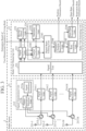
- FIG. 1 is an overall configuration diagram illustrating a vital measuring device according to a first embodiment
- FIG. 2 is a hardware configuration diagram of an infrared sensor 1 of the vital measuring device
- FIG. 3 is a hardware configuration diagram of a radar sensor 2 of the vital measuring device.
- the infrared sensor 1 and the radar sensor 2 are temporally synchronized with each other and arranged at a short distance from each other.
- a synchronization signal for achieving temporal synchronization is supplied from a synchronization signal generation unit (not illustrated) to the infrared sensor 1 and the radar sensor 2.
- the vital measuring device shown in FIG. 1 includes the infrared sensor 1, the radar sensor 2 and a final vital output unit 3.
- the infrared sensor 1 illustrated in FIG. 2 includes a light receiving unit 11, a biological recognition unit 12, and an infrared vital estimating unit 13.
- the light receiving unit 11 includes a plurality of light receiving elements arranged two-dimensionally, receives infrared light emitted from a target object, photoelectrically converts a received signal, and outputs the photoelectrically converted signal to the biological recognition unit 12 as an infrared image signal.
- the biological recognition unit 12 performs biological recognition such as human recognition or animal recognition by performing image recognition processing using machine learning or the like on the infrared image signal, and outputs a recognition result to the infrared vital estimating unit 13 as a biological recognition result.
- the infrared vital estimating unit 13 estimates a body temperature of a detected living body and estimates a two-dimensional orientation in which the living body is present.
- the biological recognition unit 12 and the infrared vital estimating unit 13 are implemented by, for example, a processor 62 and a memory 61 as illustrated in FIG. 6 , similarly to a radar vital measuring unit 22 to be described later.
- the memory 61 stores a program and a learned model for implementing processing performed by the biological recognition unit 12 and the infrared vital estimating unit 13.
- the learned model is a model in which a relationship between an infrared image and a living body is learned.
- the processor 62 reads and executes the program stored in the memory 61, thereby implementing processing performed by the biological recognition unit 12 and the infrared vital estimating unit 13.
- the radar sensor 2 illustrated in FIG. 3 includes a transmission and reception unit 21 and the radar vital measuring unit 22.
- the transmission and reception unit 21 includes N antennas 211-1 to 211-N, a signal transmission unit 212, N circulators 213-1 to 213-N, and N signal reception units 214-1 to 214-N.
- N is an integer equal to or more than two.
- Each of the antennas is a transmission and reception antenna.
- the radar sensor 2 illustrated in FIG. 3 includes N antennas in order to increase resolution of a reception signal by multiple-input multiple-output (MIMO).
- MIMO multiple-input multiple-output
- Each of the antennas also serves as a transmission antenna and a reception antenna.
- the radar sensor 2 may separately include a transmission antenna and a reception antenna.
- one antenna that emits the transmission wave is selected from the antennas 211-1 to 211-N.
- a transmission order of the transmission waves in the antennas is determined.
- the transmission order is determined in the order of the antenna 211-1, an antenna 211-2, ..., and an antenna 211-n. This is merely an example, and the transmission order may be determined in the order of the antenna 211-n, ..., the antenna 211-2, and the antenna 211-1, for example.
- the transmission wave radiated from the antenna 211-n is reflected by the target object.
- the target object includes not only a person to be measured present in the space but also a stationary object such as a wall of a room forming the space or a desk present in the space.
- Each of the antennas 211-1 to 211-N receives a reflected wave from the target object, and outputs a reception signal of the reflected wave to the circulator.
- the signal transmission unit 212 includes a signal generator 212a and an output destination selecting unit 212b.
- the signal transmission unit 212 sequentially selects one antenna 211-n that emits a transmission wave from among the N antennas. In order to radiate the transmission wave from the selected antenna 211-n to the space where the person to be measured is present, the signal transmission unit 212 outputs a transmission signal to the circulator 213-n connected to the selected antenna 211-n.
- the signal generator 212a generates, for example, a transmission signal whose frequency changes with the lapse of time or a pulse transmission signal. Examples of the transmission signal whose frequency changes with the lapse of time include an up-chirp signal and a down-chirp signal.
- the signal generator 212a outputs the transmission signal to the output destination selecting unit 212b.
- the output destination selecting unit 212b outputs the transmission signal generated by the signal generator 212a to the circulator 213-n that is connected to the antenna 211-n in the next order of emitting the transmission wave among the N circulators 213.
- the circulator 213-n outputs the reception signal output from the antenna 211-n to a signal reception unit 214-n.
- Examples of the reception processing include processing of down-converting a frequency of the reception signal and processing of converting the reception signal after frequency conversion from an analog signal to a digital signal.
- the signal reception unit 214-n outputs reception data S(t, g, h, q, c), which is a digital signal, to the radar vital measuring unit 22.
- t represents reception time of the reflected wave by the antenna 211-n.
- Q is an integer equal to or more than two.
- the radar vital measuring unit 22 includes a signal acquisition unit 221, a signal separation unit 222, a moving object estimating unit 223, and a radar vital estimating unit 224.
- the signal acquisition unit 221 acquires the reception data S(t, g, h, q, c) as the reception signal of the reflected wave from each of the signal reception units 214-1 to 214-N, and outputs the reception data S(t, g, h, q, c) to the signal separation unit 222.
- the signal separation unit 222 calculates stationary object reception data Ssta(t, g, h, c) and moving object reception data Smov(t, g, h, q, c) using the reception data S(t, g, h, q, c), outputs the calculated stationary object reception data Ssta(t, g, h, c) to the radar vital estimating unit 224, and outputs the calculated moving object reception data Smov(t, g, h, q, c) to the moving object estimating unit 223.
- the moving object estimating unit 223 acquires the moving object reception data Smov(t, g, h, q, c) from the signal separation unit 222 and estimates a two-dimensional orientation of the moving object.
- the moving object estimating unit 223 outputs the estimated two-dimensional orientation of the moving object to the radar vital estimating unit 224.
- the radar vital estimating unit 224 includes a stationary determination unit 2241, a Fourier transform unit 2242, a digital beam forming unit 2243, a presence position specifying unit 2244, a respiration rate estimating unit 2245, and a heart rate estimating unit 2246.
- the radar vital estimating unit 224 estimates a position, a respiration rate, and a heart rate of a living body from the stationary object reception data Ssta(t, g, h, c) on the basis of a detection result of the moving object detected by the moving object estimating unit 223.
- the stationary determination unit 2241 acquires the two-dimensional orientation of the moving object from the moving object estimating unit 223 and an estimation result of the two-dimensional orientation of the living body from the infrared vital estimating unit 13, respectively. It is determined whether the living body recognized by the infrared vital estimating unit 13 is stationary, and when it is determined as being stationary, a stationary determination flag is output to the Fourier transform unit 2242.
- the digital beam forming unit 2243 acquires the Fourier-transformed signal Ssta(r, g, h, c) from the Fourier transform unit 2242 and the estimation result of the two-dimensional orientation of the living body from the infrared vital estimating unit 13, respectively.
- the digital beam forming unit 2243 calculates a beam forming signal BFsta(r, c) by performing digital beam forming on the two-dimensional orientation of the living body obtained from the infrared vital estimating unit 13, and outputs the beam forming signal to the presence position specifying unit 2244.
- the presence position specifying unit 2244 acquires the beam forming signal BFsta(r, c).
- the presence position specifying unit 2244 estimates a vital feature amount for each range bin r on the basis of the beam forming signal BFsta(r, c), and calculates a biological slant range Rbio on the basis of magnitude of the vital feature amount.
- a biological signal B(c) in the biological slant range Rbio is output to the respiration rate estimating unit 2245 and the heart rate estimating unit 2246.
- the respiration rate estimating unit 2245 acquires the biological signal B(c) from the presence position specifying unit 2244. A respiration rate RR of the living body is estimated on the basis of the biological signal B(c).
- the heart rate estimating unit 2246 acquires the biological signal B(c) from the presence position specifying unit 2244. A heart rate HR of the living body is estimated on the basis of the biological signal B(c).
- each of the signal acquisition unit 221, the signal separation unit 222, the moving object estimating unit 223, and the radar vital estimating unit 224 which are components of the radar vital measuring unit 22, is implemented by dedicated hardware as illustrated in FIG. 5 . That is, it is assumed that the radar vital measuring unit 22 is implemented by a signal acquisition circuit 221C, a signal separation circuit 222C, a moving object estimating circuit 223C, and a radar vital estimating circuit 224C.
- Each of the signal acquisition circuit 221C, the signal separation circuit 222C, the moving object estimating circuit 223C, and the radar vital estimating circuit 224C corresponds to, for example, a single circuit, a composite circuit, a programmed processor, a parallel programmed processor, an application specific integrated circuit (ASIC), a field-programmable gate array (FPGA), or a combination thereof.
- ASIC application specific integrated circuit
- FPGA field-programmable gate array
- the final vital output unit 3 illustrated in FIG. 4 acquires a body temperature estimation result of the living body from the infrared sensor 1, acquires a position estimation result, a respiration rate estimation result, and a heart rate estimation result of the living body from the radar sensor 2, and outputs them to the outside.
- the final vital output unit 3 may be implemented by a dedicated processing circuit, similarly to the radar vital measuring unit 22. Further, as will be described below according to the radar vital measuring unit 22, it may be implemented by, for example, the processor 62 and the memory 61 as illustrated in FIG. 6 .
- the memory 61 stores a program for implementing processing performed by the final vital output unit 3, and the processor 62 reads and executes the program stored in the memory 61, thereby implementing the processing by the final vital output unit 3.
- the components of the radar vital measuring unit 22 are not limited to those implemented by dedicated hardware, and the radar vital measuring unit 22 may be implemented by software, firmware, or a combination of software and firmware.
- the software or firmware is stored as a program in a memory of a computer.
- the computer means hardware that executes a program, and corresponds to, for example, a central processing unit (CPU), a central processing device, a processing device, an arithmetic device, a microprocessor, a microcomputer, a processor, or a digital signal processor (DSP).
- CPU central processing unit
- DSP digital signal processor
- FIG. 6 is a hardware configuration diagram of a computer in a case where the radar vital measuring unit 22 is implemented by software, firmware, or the like.
- the radar vital measuring unit 22 is implemented by software, firmware, or the like
- a program for causing the computer to execute each processing procedure performed in the signal acquisition unit 221, the signal separation unit 222, the moving object estimating unit 223, and the radar vital estimating unit 224 is stored in the memory. Then, the processor of the computer executes the program stored in the memory.
- FIG. 5 shows an example in which each of the components of the radar vital measuring unit 22 is implemented by dedicated hardware
- FIG. 6 shows an example in which the radar vital measuring unit 22 is implemented by software, firmware, or the like.
- this is merely an example, and some components in the radar vital measuring unit 22 may be implemented by the dedicated hardware, and the remaining components may be implemented by software, firmware, or the like.
- FIG. 7 is a flowchart illustrating a vital measuring method which is a processing procedure performed by the vital measuring device.
- the infrared sensor 1 estimates a body temperature and a two-dimensional orientation of a living body. More specifically, the light receiving unit 11 of the infrared sensor 1 receives infrared light emitted from an object by the plurality of two-dimensionally arranged light receiving elements, photoelectrically converts a received signal, and outputs the photoelectrically converted signal to the biological recognition unit 12 as an infrared image signal.
- the biological recognition unit 12 of the infrared sensor 1 specifies presence and a two-dimensional position of the living body in an infrared image by image recognition processing using machine learning or the like on the infrared image signal acquired from the light receiving unit 11.
- the living body includes a person or an animal.
- the infrared vital estimating unit 13 of the infrared sensor 1 estimates a two-dimensional orientation of the living body as viewed from the vital measuring device and a body temperature of the living body on the basis of a biological recognition result, and outputs the estimated result.
- the signal generator 212a of the signal transmission unit 212 of the radar sensor 2 generates an up-chirp signal or a down-chirp signal as a transmission signal in accordance with, for example, a frequency modulated continuous wave (FMCW) method or a fast-chirp modulation (FCM) method.
- FMCW frequency modulated continuous wave
- FCM fast-chirp modulation
- the high frequency band is, for example, a millimeter wave band of about 30 to 300 GHz.
- the output destination selecting unit 212b outputs the transmission signal Tx'(n) to the circulator 213-n that is connected to the antenna 211-n in the next order of radiating the transmission wave among the N circulators 213-1 to 213-N.
- the output destination selecting unit 212b outputs a transmission signal Tx'(1) to the circulator 213-1 when the antenna 211-n in the next order of radiating the transmission wave is the antenna 211-1, and outputs a transmission signal Tx'(2) to the circulator 213-2 when the antenna 211-n in the next order of radiating the transmission wave is the antenna 211-2.
- the output destination selecting unit 212b outputs a transmission signal Tx'(N) to the circulator 213-N, for example, when the antenna 211-n in the next order of radiating the transmission wave is the antenna 211-N.
- the transmission wave radiated from the antenna 211-n is reflected by the target object. That is, the transmission wave radiated from the antenna 211-n is reflected not only by a person to be measured but also by a wall or the like forming the space.
- the reflected wave from the person to be measured may be further reflected by a wall or the like of a room where the person to be measured is present.
- the signal reception unit 214-n performs, for example, processing of down-converting a frequency of the reception signal to a frequency in an intermediate frequency band and processing of converting the reception signal after frequency conversion from an analog signal to a digital signal as the reception processing for the reception signal.
- the signal reception unit 214-n outputs each reception data S(t, g, h, q, c), which is N ⁇ Q digital signals, to the radar vital measuring unit 22.
- the signal acquisition unit 221 outputs N ⁇ N ⁇ Q pieces of reception data S(t, g, h, q, c) to the signal separation unit 222 in each transmission cycle c.
- the signal separation unit 222 separates a moving object signal and a stationary object signal.
- the signal separation unit 222 outputs moving object reception data Smov(t, g, h, q, c) obtained by subtracting the stationary object reception data Ssta(t, g, h, c) from the reception data S(t, g, h, q, c) to the moving object estimating unit 223.
- the moving object estimating unit 223 estimates a position of a moving object.
- the moving object estimating unit 223 estimates a range from the radar sensor 2 to the moving object and a velocity of the moving object by performing range Doppler processing on the moving object present in the space on the basis of the acquired N ⁇ N ⁇ Q pieces of moving object reception data Smov(t, g, h, q, c). Since the range Doppler processing itself is a known technique, detailed description thereof will be omitted.
- a range to one moving object and a velocity of the moving object are estimated.
- a first moving object and a second moving object are present in the space as two moving objects, a range to the first moving object and a velocity of the first moving object, and a range to the second moving object and a velocity of the second moving object are estimated.
- the moving object estimating unit 223 detects a two-dimensional orientation in which the moving object is present by performing angle measuring processing on the basis of estimation results of the range to the moving object and the velocity of the moving object.
- the two-dimensional orientation has an azimuth direction in which the moving object is viewed from the vital measuring device and an elevation direction in which the moving object is viewed from the vital measuring device.
- step ST5 the stationary determination unit 2241 determines whether or not the living body detected by the infrared sensor 1 is stationary. In order to make this determination, the stationary determination unit 2241 acquires a two-dimensional orientation of the moving object from the moving object estimating unit 223, and acquires an estimation result of the two-dimensional orientation of the living body from the infrared vital estimating unit 13, respectively.
- the stationary determination unit 2241 determines that the living body detected by the infrared sensor 1 is moving.
- the stationary determination unit 2241 determines that the living body detected by the infrared sensor 1 is stationary and outputs a stationary determination flag to the Fourier transform unit 2242.
- step ST6 the Fourier transform unit 2242 performs Fourier transform on each of the N ⁇ N ⁇ Q pieces of stationary object reception data Ssta(t, g, h, c) in a time direction in each transmission cycle c.
- the signals Ssta(r, g, h, c) after the Fourier transform by the Fourier transform unit 2242 are signals indicating complex power corresponding to the range bin r as illustrated in FIG. 9.
- FIG. 9 is an explanatory diagram illustrating N pieces of Fourier-transformed signals Ssta(r, g, h, c) in a certain transmission cycle c.
- the horizontal axis represents the range bin and the vertical axis represents the complex power.
- the Fourier transform unit 2242 outputs N pieces of Fourier-transformed signals Ssta(r, g, h, c) to the digital beam forming unit 2243 in each transmission cycle c.
- step ST7 the digital beam forming unit 2243 performs two-dimensional beam forming on the stationary object signal in a biological detection orientation in the infrared sensor 1, and calculates a beam forming signal BF(r, c).
- the digital beam forming unit 2243 acquires the Fourier-transformed signal Ssta(r, g, h, c) from the Fourier transform unit 2242 and the estimation result of the two-dimensional orientation of the living body from the infrared vital estimating unit 13, respectively.
- the digital beam forming unit 2243 calculates the beam forming signal BF(r, c) by performing digital beam forming on the two-dimensional orientation of the living body obtained from the infrared vital estimating unit 13, and outputs the calculated beam forming signal BF(r, c) to the presence position specifying unit 2244.
- the digital beam forming unit 2243 performs, on each Fourier-transformed signal Ssta(r, g, h, c), two-dimensional orientation beam forming processing by digital beam forming (DBF) toward the two-dimensional orientation of the living body obtained from the infrared vital estimating unit 13 for each range bin r.
- the two-dimensional orientation includes the azimuth direction and the elevation direction.
- the digital beam forming may be performed using another method such as a Capon method. Note that the two-dimensional orientation beam forming processing itself is a known technique, and thus a detailed description thereof will be omitted.
- the digital beam forming unit 2243 outputs a beam forming signal BF(r, c) corresponding to each range bin r to the presence position specifying unit 2244.
- the presence position specifying unit 2244 estimates a remaining biological slant range necessary for estimating a three-dimensional position of the living body.
- position specifying processing by the presence position specifying unit 2244 will be specifically described.
- the respiration signal is a signal indicating a phase variation caused by a reciprocating motion in a chest of the living body. Therefore, the beam forming signals BF(r, c) belonging to the same range bin (slant range bin) r are time-varying signals, and exhibit the reciprocating motion on a circumference as time passes in a complex signal space as illustrated in FIG. 10.
- FIG. 10 is an explanatory diagram illustrating temporal changes of phases of beam forming signals BF(r, c) belonging to the same range bin r.
- the beam forming signals BF(r, c) exhibit the reciprocating motion on the circumference in the complex signal space.
- the evaluation function J( ⁇ , ⁇ ) can be expressed in a matrix form as shown in the following Formula (2) by formula deformation.
- * is a mathematical symbol representing a complex conjugate.
- the presence position specifying unit 2244 estimates a parameter vector p shown in Formula (2) using the least squares method as shown in Formula (3) below.
- p ⁇ H ⁇ s
- + is a mathematical symbol representing a pseudo inverse matrix.
- ⁇ displayed above the letter p is a symbol indicating an estimation result of the parameter vector p.
- the presence position specifying unit 2244 can obtain the center ⁇ of the fitting circle Circ(r) and the radius ⁇ of the fitting circle Circ(r) as expressed by the following Formulas (5) and (6).
- the fitting circle Circ(r) is calculated.
- Re( ⁇ ) represents a real part of a complex number ⁇
- Im(o) represents an imaginary part of the complex number ⁇ .
- the presence position specifying unit 2244 calculates the fitting circle Circ(r) using a circle fitting method called Kasa fit.
- a circle fitting method such as Pratt fit, Taubin fit, or Hyper fit.
- the presence position specifying unit 2244 calculates a fitting error E(r) which is an error of the fitting circle Circ(r) as expressed in the following Formula (7).
- ⁇ (r) is the center of the fitting circle Circ(r), and ⁇ (r) is the radius of the fitting circle Circ(r).
- the radius ⁇ of the fitting circle Circ(r) becomes large and the fitting error E(r) becomes small.
- the reflected wave is a reflected wave from a stationary object such as a wall, that is, a direct wave from the stationary object, the radius ⁇ of the fitting circle Circ(r) becomes small and the fitting error E(r) becomes large.
- the presence position specifying unit 2244 sets the calculated r fitting errors E(r) as vital feature amounts, and compares the fitting errors E(r) in a range bin r direction. That is, the presence position specifying unit 2244 compares the fitting errors E(r), which are the vital feature amounts, between the slant range bins. On the basis of a result of this comparison, the presence position specifying unit 2244 estimates a range bin r0, at which the fitting error E(r) is minimized, as the slant range to the living body.
- FIG. 11 is an explanatory diagram illustrating a change of the fitting error E(r) with respect to the range bin r.
- FIG. 11 illustrates a state in which the fitting error E(r) is minimized in the range bin r0.
- the respiration rate estimating unit 2245 can use, for example, an arctangent demodulation (AD) method or a complex signal demodulation (CSD) method as a method of calculating the phase change signal ⁇ (c) for a position where the living body is present.
- AD arctangent demodulation
- CSD complex signal demodulation
- the respiration rate estimating unit 2245 estimates the respiration rate RR of the living body by performing Fourier transform on the phase change signal ⁇ (c). Note that a technique for estimating the respiration rate RR using the phase change signal ⁇ (c) itself is a known technique, and thus a detailed description thereof is omitted.
- the heart rate estimating unit 2246 can also use, for example, the AD method or the CSD method as the method of calculating the phase change signal ⁇ (c) for the position where the living body is present, but it is not necessary to use the same method as that of the respiration rate estimating unit 2245.
- the heart rate estimating unit 2246 estimates a heart rate HR of the living body by performing Fourier transform or wavelet transform on the phase change signal ⁇ (c). Note that a technique for estimating the heart rate HR using the phase change signal ⁇ (c) itself is a known technique, and thus a detailed description thereof is omitted.
- step ST11 the final vital output unit 3 acquires a body temperature estimation result of the living body from the infrared sensor 1, acquires a position estimation result, a respiration rate estimation result, and a heart rate estimation result of the living body from the radar sensor 2, and outputs them to the outside.
- a configuration is the same as that of the first embodiment, but the radius ⁇ (r) of the fitting circle Circ(r) is used as the vital feature amount in the presence position specifying unit 2244.
- the presence position specifying unit 2244 sets calculated R fitting circle radii ⁇ (r) as the vital feature amounts, compares the fitting circle radii ⁇ (r) in the range bin r direction, and estimates a range bin r0, at which the fitting circle radius ⁇ (r) is maximized, as the slant range to the living body.
- the presence position specifying unit 2244 sets calculated R occupancy angle widths W(r) as the vital feature amounts, compares the occupancy angle widths W(r) in the range bin r direction, and estimates a range bin r0, at which the occupancy angle width W(r) is maximized, as the slant range to the living body.
- FIG. 10 illustrates the occupancy angle width W(r).
- a configuration is the same as that of the first embodiment, but an inner product of a radial direction vector A(c) from the circle center ⁇ (r) of the fitting circle Circ(r) toward each signal point (time-varying signal point) of the beam forming signal BF(r, c) and a line segment vector B(c) connecting adjacent signal points of the beam forming signal BF(r, c) is calculated, and a total value I(r) of inner product values corresponding to all the beam forming signal points is set as the vital feature amount in the presence position specifying unit 2244.
- the total value I(r) of the inner product values is calculated by Formula (8).
- the presence position specifying unit 2244 sets the calculated R inner product total values I(r) as vital feature amounts, compares the inner product total values I(r) in the range bin r direction, and estimates the range bin r0 at which the inner product total value I(r) is minimum as the slant range to the living body.
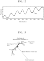
- FIG. 13 illustrates an example of vectors used to calculate an inner product value corresponding to a certain adjacent beam forming signal point pair.
- the vital measuring technique of the present disclosure can be used as a vital measuring device that measures vitals of one or a small number of elderly people.
Landscapes
- Health & Medical Sciences (AREA)
- Life Sciences & Earth Sciences (AREA)
- Engineering & Computer Science (AREA)
- Physics & Mathematics (AREA)
- Molecular Biology (AREA)
- General Health & Medical Sciences (AREA)
- Veterinary Medicine (AREA)
- Public Health (AREA)
- Animal Behavior & Ethology (AREA)
- Biophysics (AREA)
- Pathology (AREA)
- Biomedical Technology (AREA)
- Heart & Thoracic Surgery (AREA)
- Medical Informatics (AREA)
- Surgery (AREA)
- Physiology (AREA)
- Cardiology (AREA)
- Nuclear Medicine, Radiotherapy & Molecular Imaging (AREA)
- Signal Processing (AREA)
- Pulmonology (AREA)
- Radiology & Medical Imaging (AREA)
- Psychiatry (AREA)
- Computer Vision & Pattern Recognition (AREA)
- Artificial Intelligence (AREA)
- Dentistry (AREA)
- Oral & Maxillofacial Surgery (AREA)
- Spectroscopy & Molecular Physics (AREA)
- Measuring Pulse, Heart Rate, Blood Pressure Or Blood Flow (AREA)
- Measurement Of The Respiration, Hearing Ability, Form, And Blood Characteristics Of Living Organisms (AREA)
- Measuring And Recording Apparatus For Diagnosis (AREA)
Abstract
Description
- The present disclosure relates to a vital measuring technique.
- There is a measuring system that combines a single infrared sensor and a plurality of radar sensors to measure vital signs of a plurality of persons to be measured (see Non-Patent Literature 1). Note that, in the present disclosure, a term "vital" is used as a term meaning the vital signs.
- The infrared sensor of the measuring system includes a sensitivity sensor that receives infrared light emitted from a person to be measured and outputs a light reception signal. The infrared sensor can estimate the number and positions of the persons to be measured even under a low illuminance condition while considering privacy.
- The radar sensor of the measuring system includes an antenna that transmits a microwave or a millimeter wave toward a person to be measured present in a room, receives a reflected wave that is the microwave or the millimeter wave after being reflected by the person to be measured, and outputs a reception signal of the reflected wave. In addition, the radar sensor includes a first mixer that extracts an in-phase signal included in the reception signal output from the antenna, a second mixer that extracts a quadrature signal included in the reception signal output from the antenna, and a signal processing device that generates a complex signal including the in-phase signal and the quadrature signal. Respiration rates and heart rates of the plurality of persons to be measured are estimated using the plurality of complex signals obtained from the plurality of radar sensors on the basis of an estimation result of the positions of the persons to be measured by the infrared sensor.
- Non-Patent Literature 1: De-Ming Chian, Chao-Kai Wen, Chang-Jen Wang, Ming-Huan Hsu, and Fu-Kang Wang, "Vital Signs Identification System with Doppler Radars and Thermal Camera", IEEE Transactions on Biomedical Circuits and Systems, vol. 16, no. 1, pp. 153-167, Feb. 2022.
- The measuring system disclosed in
Non-Patent Literature 1 relates to measuring of vitals of a plurality of persons to be measured closely seated in a room. In order to detect the vitals of the plurality of closely spaced persons to be measured, it is necessary to use a plurality of radar sensors dispersedly arranged in the room, so that the measuring system is expensive. On the other hand, in watching over an elderly person in a service-equipped elderly residence or the like, in general, there are few cases of a plurality of persons whose vitals to be measured, and in many cases, it is sufficient if vitals of one elderly person can be constantly measured. In that case, there is a problem that the measuring system involves a high cost with respect to required performance. - The present disclosure has been made in view of the above problem, and an object of the present disclosure is to provide a vital measuring technique capable of detecting vitals of a person to be measured by using only a single infrared sensor and a single radar sensor.
- An aspect of a vital measuring device according to embodiments of the present disclosure includes: a single infrared sensor including a light receiving unit to receive infrared light emitted from a target object and capture an infrared image, a biological recognition unit to recognize a living body from the infrared image captured by the light receiving unit, and an infrared vital estimating unit to estimate a body temperature and a two-dimensional orientation of the living body recognized by the biological recognition unit; a single radar sensor temporally synchronized with the infrared sensor and disposed in proximity to the infrared sensor in such a manner as to sense the living body, the single radar sensor including a signal acquisition unit to acquire a reception signal of a reflected wave from an antenna for receiving the reflected wave from the target object, a signal separation unit to separate the reception signal acquired by the signal acquisition unit into a moving object signal and a stationary object signal, a moving object estimating unit to detect a moving object by estimating a range, a velocity, and a two-dimensional orientation of the moving object from the moving object signal, and a radar vital estimating unit to estimate a position, a respiration rate, and a heart rate of the living body from the stationary object signal on a basis of a detection result of the moving object detected by the moving object estimating unit; and a final vital output unit to acquire the position, the respiration rate, and the heart rate of the living body estimated by the radar vital estimating unit, acquire the body temperature of the living body estimated by the infrared vital estimating unit, to output the acquired position, body temperature, respiration rate, and heart rate of the living body.
- According to a vital measuring technique according to the embodiments of the present disclosure, it is possible to detect vitals of a person to be measured by using only a single infrared sensor and a single radar sensor.
-
-
FIG. 1 is an overall configuration diagram illustrating a vital measuring device according to a first embodiment. -
FIG. 2 is a hardware configuration diagram of an infrared sensor of the vital measuring device according to the first embodiment. -
FIG. 3 is a hardware configuration diagram of a radar sensor of the vital measuring device according to the first embodiment. -
FIG. 4 is a configuration diagram of a finalvital output unit 3 of the vital measuring device according to the first embodiment. -
FIG. 5 is a hardware configuration diagram illustrating hardware of the vital measuring device according to the first embodiment. -
FIG. 6 is a hardware configuration diagram of a computer in a case where the vital measuring device is implemented by software, firmware, or the like. -
FIG. 7 is a flowchart illustrating a vital measuring method which is a processing procedure performed by the vital measuring device. -
FIG. 8 is an explanatory diagram illustrating up-chirp signals Tx(1) to Tx(N) with the number of hits Q generated by asignal generator 212a. -
FIG. 9 is an explanatory diagram illustrating Fourier-transformed signals Ssta(r, g, h, c) of N pieces of stationary object reception data in a certain transmission cycle c. -
FIG. 10 is an explanatory diagram illustrating beam forming signals BF(r, c) belonging to the same range bin r. -
FIG. 11 is an explanatory diagram illustrating a change of a circle fitting error E(r) with respect to the range bin r. -
FIG. 12 is an explanatory diagram illustrating a phase change signal θ(c) at a range bin r0. -
FIG. 13 is an explanatory diagram illustrating vectors used for calculation of an inner product value corresponding to a certain adjacent beam forming signal point pair of the beam forming signals BF(r, c) belonging to the same range bin r. - Hereinafter, various embodiments of the present disclosure will be described in detail with reference to the accompanying drawings. Note that components denoted by the same or similar reference numerals in the drawings have the same or similar configurations or functions, and redundant description of such components will be omitted.
-
FIG. 1 is an overall configuration diagram illustrating a vital measuring device according to a first embodiment,FIG. 2 is a hardware configuration diagram of aninfrared sensor 1 of the vital measuring device, andFIG. 3 is a hardware configuration diagram of aradar sensor 2 of the vital measuring device. As will be described later, in order for theradar sensor 2 to perform beam forming in a two-dimensional orientation of a measurement target detected by theinfrared sensor 1, theinfrared sensor 1 and theradar sensor 2 are temporally synchronized with each other and arranged at a short distance from each other. A synchronization signal for achieving temporal synchronization is supplied from a synchronization signal generation unit (not illustrated) to theinfrared sensor 1 and theradar sensor 2. - The vital measuring device shown in
FIG. 1 includes theinfrared sensor 1, theradar sensor 2 and a finalvital output unit 3. - The
infrared sensor 1 illustrated inFIG. 2 includes alight receiving unit 11, abiological recognition unit 12, and an infraredvital estimating unit 13. Thelight receiving unit 11 includes a plurality of light receiving elements arranged two-dimensionally, receives infrared light emitted from a target object, photoelectrically converts a received signal, and outputs the photoelectrically converted signal to thebiological recognition unit 12 as an infrared image signal. Thebiological recognition unit 12 performs biological recognition such as human recognition or animal recognition by performing image recognition processing using machine learning or the like on the infrared image signal, and outputs a recognition result to the infrared vital estimatingunit 13 as a biological recognition result. By using the biological recognition result, the infrared vital estimatingunit 13 estimates a body temperature of a detected living body and estimates a two-dimensional orientation in which the living body is present. Thebiological recognition unit 12 and the infrared vital estimatingunit 13 are implemented by, for example, aprocessor 62 and amemory 61 as illustrated inFIG. 6 , similarly to a radarvital measuring unit 22 to be described later. Thememory 61 stores a program and a learned model for implementing processing performed by thebiological recognition unit 12 and the infraredvital estimating unit 13. The learned model is a model in which a relationship between an infrared image and a living body is learned. Theprocessor 62 reads and executes the program stored in thememory 61, thereby implementing processing performed by thebiological recognition unit 12 and the infrared vital estimatingunit 13. - The
radar sensor 2 illustrated inFIG. 3 includes a transmission andreception unit 21 and the radarvital measuring unit 22. - The transmission and
reception unit 21 includes N antennas 211-1 to 211-N, asignal transmission unit 212, N circulators 213-1 to 213-N, and N signal reception units 214-1 to 214-N. N is an integer equal to or more than two. Each of the antennas is a transmission and reception antenna. Theradar sensor 2 illustrated inFIG. 3 includes N antennas in order to increase resolution of a reception signal by multiple-input multiple-output (MIMO). Each of the antennas also serves as a transmission antenna and a reception antenna. However, this is merely an example, and theradar sensor 2 may separately include a transmission antenna and a reception antenna. - When a transmission wave is emitted from the
radar sensor 2, one antenna that emits the transmission wave is selected from the antennas 211-1 to 211-N. A transmission order of the transmission waves in the antennas is determined. For example, the transmission order is determined in the order of the antenna 211-1, an antenna 211-2, ..., and an antenna 211-n. This is merely an example, and the transmission order may be determined in the order of the antenna 211-n, ..., the antenna 211-2, and the antenna 211-1, for example. - The antenna 211-n (n = 1, ..., N) radiates a transmission wave related to a transmission signal output from a circulator 213-n to a space where a target object is present. The transmission wave radiated from the antenna 211-n is reflected by the target object. The target object includes not only a person to be measured present in the space but also a stationary object such as a wall of a room forming the space or a desk present in the space.
- Each of the antennas 211-1 to 211-N receives a reflected wave from the target object, and outputs a reception signal of the reflected wave to the circulator.
- The
signal transmission unit 212 includes asignal generator 212a and an outputdestination selecting unit 212b. Thesignal transmission unit 212 sequentially selects one antenna 211-n that emits a transmission wave from among the N antennas. In order to radiate the transmission wave from the selected antenna 211-n to the space where the person to be measured is present, thesignal transmission unit 212 outputs a transmission signal to the circulator 213-n connected to the selected antenna 211-n. - The
signal generator 212a generates, for example, a transmission signal whose frequency changes with the lapse of time or a pulse transmission signal. Examples of the transmission signal whose frequency changes with the lapse of time include an up-chirp signal and a down-chirp signal. Thesignal generator 212a outputs the transmission signal to the outputdestination selecting unit 212b. - The output
destination selecting unit 212b outputs the transmission signal generated by thesignal generator 212a to the circulator 213-n that is connected to the antenna 211-n in the next order of emitting the transmission wave among theN circulators 213. - The circulator 213-n (n = 1, ..., N) outputs the transmission signal output from the output
destination selecting unit 212b to the antenna 211-n. In addition, the circulator 213-n outputs the reception signal output from the antenna 211-n to a signal reception unit 214-n. - The signal reception unit 214-n (n = 1, ..., N) performs reception processing on the reception signal output from the circulator 213-n. Examples of the reception processing include processing of down-converting a frequency of the reception signal and processing of converting the reception signal after frequency conversion from an analog signal to a digital signal.
- The signal reception unit 214-n outputs reception data S(t, g, h, q, c), which is a digital signal, to the radar
vital measuring unit 22. t represents reception time of the reflected wave by the antenna 211-n. g is a variable for identifying the antenna 211-n that has radiated the transmission wave, and g = 1, ..., N. h is a variable for identifying the antenna 211-n that has received the reflected wave, and h = 1, ..., N. q is a variable that identifies a hit number in a certain transmission cycle, and q = 1, ..., Q. Q is an integer equal to or more than two. c is a variable for identifying a transmission cycle of the transmission wave by the antennas 211-1 to 211-N, and c = 1, ..., C. C is an integer equal to or more than two. - The radar
vital measuring unit 22 includes asignal acquisition unit 221, asignal separation unit 222, a movingobject estimating unit 223, and a radarvital estimating unit 224. - The
signal acquisition unit 221 acquires the reception data S(t, g, h, q, c) as the reception signal of the reflected wave from each of the signal reception units 214-1 to 214-N, and outputs the reception data S(t, g, h, q, c) to thesignal separation unit 222. - The
signal separation unit 222 calculates stationary object reception data Ssta(t, g, h, c) and moving object reception data Smov(t, g, h, q, c) using the reception data S(t, g, h, q, c), outputs the calculated stationary object reception data Ssta(t, g, h, c) to the radarvital estimating unit 224, and outputs the calculated moving object reception data Smov(t, g, h, q, c) to the movingobject estimating unit 223. - The moving
object estimating unit 223 acquires the moving object reception data Smov(t, g, h, q, c) from thesignal separation unit 222 and estimates a two-dimensional orientation of the moving object. The movingobject estimating unit 223 outputs the estimated two-dimensional orientation of the moving object to the radarvital estimating unit 224. - The radar
vital estimating unit 224 includes astationary determination unit 2241, aFourier transform unit 2242, a digitalbeam forming unit 2243, a presenceposition specifying unit 2244, a respirationrate estimating unit 2245, and a heartrate estimating unit 2246. The radarvital estimating unit 224 estimates a position, a respiration rate, and a heart rate of a living body from the stationary object reception data Ssta(t, g, h, c) on the basis of a detection result of the moving object detected by the movingobject estimating unit 223. - The
stationary determination unit 2241 acquires the two-dimensional orientation of the moving object from the movingobject estimating unit 223 and an estimation result of the two-dimensional orientation of the living body from the infraredvital estimating unit 13, respectively. It is determined whether the living body recognized by the infraredvital estimating unit 13 is stationary, and when it is determined as being stationary, a stationary determination flag is output to theFourier transform unit 2242. - When the stationary determination flag is acquired from the
stationary determination unit 2241, theFourier transform unit 2242 performs Fourier transform on the stationary object reception data Ssta(t, g, h, c) input from thesignal separation unit 222 in a time direction. Examples of the Fourier transform include fast Fourier transform (FFT) and discrete Fourier transform (DFT). TheFourier transform unit 2242 outputs each Fourier-transformed signal Ssta(r, g, h, c) to the digital forming unit. r is a variable identifying a range bin from the vital measuring device. r = 1, ..., R. R is an integer equal to or more than two. - The digital
beam forming unit 2243 acquires the Fourier-transformed signal Ssta(r, g, h, c) from theFourier transform unit 2242 and the estimation result of the two-dimensional orientation of the living body from the infraredvital estimating unit 13, respectively. The digitalbeam forming unit 2243 calculates a beam forming signal BFsta(r, c) by performing digital beam forming on the two-dimensional orientation of the living body obtained from the infraredvital estimating unit 13, and outputs the beam forming signal to the presenceposition specifying unit 2244. - The presence
position specifying unit 2244 acquires the beam forming signal BFsta(r, c). The presenceposition specifying unit 2244 estimates a vital feature amount for each range bin r on the basis of the beam forming signal BFsta(r, c), and calculates a biological slant range Rbio on the basis of magnitude of the vital feature amount. A biological signal B(c) in the biological slant range Rbio is output to the respirationrate estimating unit 2245 and the heartrate estimating unit 2246. - The respiration
rate estimating unit 2245 acquires the biological signal B(c) from the presenceposition specifying unit 2244. A respiration rate RR of the living body is estimated on the basis of the biological signal B(c). - The heart
rate estimating unit 2246 acquires the biological signal B(c) from the presenceposition specifying unit 2244. A heart rate HR of the living body is estimated on the basis of the biological signal B(c). - In
FIG. 3 , it is assumed that each of thesignal acquisition unit 221, thesignal separation unit 222, the movingobject estimating unit 223, and the radarvital estimating unit 224, which are components of the radarvital measuring unit 22, is implemented by dedicated hardware as illustrated inFIG. 5 . That is, it is assumed that the radarvital measuring unit 22 is implemented by asignal acquisition circuit 221C, asignal separation circuit 222C, a movingobject estimating circuit 223C, and a radarvital estimating circuit 224C. Each of thesignal acquisition circuit 221C, thesignal separation circuit 222C, the movingobject estimating circuit 223C, and the radarvital estimating circuit 224C corresponds to, for example, a single circuit, a composite circuit, a programmed processor, a parallel programmed processor, an application specific integrated circuit (ASIC), a field-programmable gate array (FPGA), or a combination thereof. - The final
vital output unit 3 illustrated inFIG. 4 acquires a body temperature estimation result of the living body from theinfrared sensor 1, acquires a position estimation result, a respiration rate estimation result, and a heart rate estimation result of the living body from theradar sensor 2, and outputs them to the outside. The finalvital output unit 3 may be implemented by a dedicated processing circuit, similarly to the radarvital measuring unit 22. Further, as will be described below according to the radarvital measuring unit 22, it may be implemented by, for example, theprocessor 62 and thememory 61 as illustrated inFIG. 6 . Thememory 61 stores a program for implementing processing performed by the finalvital output unit 3, and theprocessor 62 reads and executes the program stored in thememory 61, thereby implementing the processing by the finalvital output unit 3. - The components of the radar
vital measuring unit 22 are not limited to those implemented by dedicated hardware, and the radarvital measuring unit 22 may be implemented by software, firmware, or a combination of software and firmware. - The software or firmware is stored as a program in a memory of a computer. The computer means hardware that executes a program, and corresponds to, for example, a central processing unit (CPU), a central processing device, a processing device, an arithmetic device, a microprocessor, a microcomputer, a processor, or a digital signal processor (DSP).
-
FIG. 6 is a hardware configuration diagram of a computer in a case where the radarvital measuring unit 22 is implemented by software, firmware, or the like. - In a case where the radar
vital measuring unit 22 is implemented by software, firmware, or the like, a program for causing the computer to execute each processing procedure performed in thesignal acquisition unit 221, thesignal separation unit 222, the movingobject estimating unit 223, and the radarvital estimating unit 224 is stored in the memory. Then, the processor of the computer executes the program stored in the memory. - Further,
FIG. 5 shows an example in which each of the components of the radarvital measuring unit 22 is implemented by dedicated hardware, andFIG. 6 shows an example in which the radarvital measuring unit 22 is implemented by software, firmware, or the like. However, this is merely an example, and some components in the radarvital measuring unit 22 may be implemented by the dedicated hardware, and the remaining components may be implemented by software, firmware, or the like. - Next, an operation of the vital measuring device shown in
FIG. 1 will be described with reference toFIG. 7. FIG. 7 is a flowchart illustrating a vital measuring method which is a processing procedure performed by the vital measuring device. - In step ST1 of
FIG. 7 , theinfrared sensor 1 estimates a body temperature and a two-dimensional orientation of a living body. More specifically, thelight receiving unit 11 of theinfrared sensor 1 receives infrared light emitted from an object by the plurality of two-dimensionally arranged light receiving elements, photoelectrically converts a received signal, and outputs the photoelectrically converted signal to thebiological recognition unit 12 as an infrared image signal. - The
biological recognition unit 12 of theinfrared sensor 1 specifies presence and a two-dimensional position of the living body in an infrared image by image recognition processing using machine learning or the like on the infrared image signal acquired from thelight receiving unit 11. The living body includes a person or an animal. - The infrared
vital estimating unit 13 of theinfrared sensor 1 estimates a two-dimensional orientation of the living body as viewed from the vital measuring device and a body temperature of the living body on the basis of a biological recognition result, and outputs the estimated result. - The
signal generator 212a of thesignal transmission unit 212 of theradar sensor 2 generates an up-chirp signal or a down-chirp signal as a transmission signal in accordance with, for example, a frequency modulated continuous wave (FMCW) method or a fast-chirp modulation (FCM) method. - In the
radar sensor 2 illustrated inFIG. 3 , thesignal generator 212a repeats radio wave transmission by the number ofhits 1 to Q in each transmission cycle c (c = 1, ..., C), as illustrated inFIG. 8 . Furthermore, within each hit, an up-chirp signal Tx(n) is repeatedly generated by the number of antennas 211-1 to 211-N. Therefore, thesignal generator 212a generates N × Q × C up-chirp signals Tx(n) in total. In an example ofFIG. 8 , N = 3. Thesignal generator 212a up-converts a frequency of the generated up-chirp signal Tx(n) (n = 1, ..., N) into a signal in a high frequency band, and outputs the up-converted signal as a transmission signal Tx'(n) to the outputdestination selecting unit 212b. The high frequency band is, for example, a millimeter wave band of about 30 to 300 GHz. - The output
destination selecting unit 212b acquires the transmission signal Tx'(n) (n = 1, ..., N) from thesignal generator 212a in each transmission cycle c (c = 1, ..., C) and each hit q (q = 1, ..., Q). The outputdestination selecting unit 212b outputs the transmission signal Tx'(n) to the circulator 213-n that is connected to the antenna 211-n in the next order of radiating the transmission wave among the N circulators 213-1 to 213-N. For example, the outputdestination selecting unit 212b outputs a transmission signal Tx'(1) to the circulator 213-1 when the antenna 211-n in the next order of radiating the transmission wave is the antenna 211-1, and outputs a transmission signal Tx'(2) to the circulator 213-2 when the antenna 211-n in the next order of radiating the transmission wave is the antenna 211-2. In addition, the outputdestination selecting unit 212b outputs a transmission signal Tx'(N) to the circulator 213-N, for example, when the antenna 211-n in the next order of radiating the transmission wave is the antenna 211-N. - Upon receiving the transmission signal Tx'(n) from the output
destination selecting unit 212b, the circulator 213-n (n = 1, ..., N) outputs the transmission signal Tx'(n) to the antenna 211-n. - When receiving the transmission signal Tx'(n) from the circulator 213-n, the antenna 211-n (n = 1, ..., N) radiates a transmission wave, which is a radio wave related to the transmission signal Tx'(n), to a space where a target object is present. The transmission wave radiated from the antenna 211-n is reflected by the target object. That is, the transmission wave radiated from the antenna 211-n is reflected not only by a person to be measured but also by a wall or the like forming the space. The reflected wave from the person to be measured may be further reflected by a wall or the like of a room where the person to be measured is present.
- In each transmission cycle c (c = 1, ..., C) and each hit q (q = 1, ..., Q), since one antenna among the N antennas 211-1 to 211-N sequentially radiates the transmission wave into the space N times, each of the antennas 211-1 to 211-N receives the reflected wave N × Q times in each transmission cycle c.
- The antenna 211-n (n = 1, ..., N) outputs a reception signal including the reflected wave from the target object to the circulator 213-n. The circulator 213-n (n = 1, ..., N) outputs the reception signal output from the antenna 211-n to the signal reception unit 214-n.
- The signal reception unit 214-n (n = 1, ..., N) performs reception processing on each of the N × Q reception signals output from the circulator 213-n in each transmission cycle c (c = 1, ..., C). The signal reception unit 214-n performs, for example, processing of down-converting a frequency of the reception signal to a frequency in an intermediate frequency band and processing of converting the reception signal after frequency conversion from an analog signal to a digital signal as the reception processing for the reception signal. In each transmission cycle c, the signal reception unit 214-n outputs each reception data S(t, g, h, q, c), which is N × Q digital signals, to the radar
vital measuring unit 22. As a result, in each transmission cycle c (c = 1, ..., C), a total of N × N × Q (= G × H × Q) pieces of reception data S(t, g, h, q, c) are provided from the signal reception units 214-1 to 214-N to the radarvital measuring unit 22. - In step ST2, the
signal acquisition unit 221 of the radarvital measuring unit 22 acquires N × N × Q pieces of reception data S(t, g, h, q, c) from the signal reception units 214-1 to 214-N in each transmission cycle c (c = 1, ..., C). Thesignal acquisition unit 221 outputs N × N × Q pieces of reception data S(t, g, h, q, c) to thesignal separation unit 222 in each transmission cycle c. - In step ST3, the
signal separation unit 222 separates a moving object signal and a stationary object signal. First, thesignal separation unit 222 acquires N × N × Q pieces of reception data S(t, g, h, q, c) from thesignal acquisition unit 221 in each transmission cycle c (c = 1, ..., C). Next, thesignal separation unit 222 outputs stationary object reception data Ssta(t, g, h, c) obtained by averaging all the hits q (q = 1, ..., Q) with respect to the reception data S(t, g, h, q, c) to the radarvital estimating unit 224. Further, thesignal separation unit 222 outputs moving object reception data Smov(t, g, h, q, c) obtained by subtracting the stationary object reception data Ssta(t, g, h, c) from the reception data S(t, g, h, q, c) to the movingobject estimating unit 223. - In step ST4, the moving
object estimating unit 223 estimates a position of a moving object. First, the movingobject estimating unit 223 acquires N × N × Q pieces of moving object reception data Smov(t, g, h, q, c) from thesignal separation unit 222 in each transmission cycle c (c = 1, ..., C). The movingobject estimating unit 223 estimates a range from theradar sensor 2 to the moving object and a velocity of the moving object by performing range Doppler processing on the moving object present in the space on the basis of the acquired N × N × Q pieces of moving object reception data Smov(t, g, h, q, c). Since the range Doppler processing itself is a known technique, detailed description thereof will be omitted. For example, when the number of moving objects present in the space is one, a range to one moving object and a velocity of the moving object are estimated. For example, when a first moving object and a second moving object are present in the space as two moving objects, a range to the first moving object and a velocity of the first moving object, and a range to the second moving object and a velocity of the second moving object are estimated. The movingobject estimating unit 223 detects a two-dimensional orientation in which the moving object is present by performing angle measuring processing on the basis of estimation results of the range to the moving object and the velocity of the moving object. The two-dimensional orientation has an azimuth direction in which the moving object is viewed from the vital measuring device and an elevation direction in which the moving object is viewed from the vital measuring device. - In step ST5, the
stationary determination unit 2241 determines whether or not the living body detected by theinfrared sensor 1 is stationary. In order to make this determination, thestationary determination unit 2241 acquires a two-dimensional orientation of the moving object from the movingobject estimating unit 223, and acquires an estimation result of the two-dimensional orientation of the living body from the infraredvital estimating unit 13, respectively. When an error between the two-dimensional orientation where the moving object is present obtained from the movingobject estimating unit 223 and the two-dimensional orientation of the living body obtained from the infraredvital estimating unit 13 is less than a predetermined threshold, thestationary determination unit 2241 determines that the living body detected by theinfrared sensor 1 is moving. On the other hand, when the error is equal to or larger than the predetermined threshold, thestationary determination unit 2241 determines that the living body detected by theinfrared sensor 1 is stationary and outputs a stationary determination flag to theFourier transform unit 2242. - When the stationary determination flag is acquired from the stationary determination unit 2241 (Yes in step ST5), the processing proceeds to step ST6. In step ST6, the
Fourier transform unit 2242 performs Fourier transform on each of the N × N × Q pieces of stationary object reception data Ssta(t, g, h, c) in a time direction in each transmission cycle c. In each transmission cycle c, each of the N pieces of stationary object reception data Ssta(t, g, h = n, c) related to each antenna 211-n is Fourier-transformed by theFourier transform unit 2242, whereby N pieces of Fourier-transformed signals Ssta(r, g, h, c) are generated. The signals Ssta(r, g, h, c) after the Fourier transform by theFourier transform unit 2242 are signals indicating complex power corresponding to the range bin r as illustrated inFIG. 9. FIG. 9 is an explanatory diagram illustrating N pieces of Fourier-transformed signals Ssta(r, g, h, c) in a certain transmission cycle c. InFIG. 9 , the horizontal axis represents the range bin and the vertical axis represents the complex power. TheFourier transform unit 2242 outputs N pieces of Fourier-transformed signals Ssta(r, g, h, c) to the digitalbeam forming unit 2243 in each transmission cycle c. - In step ST7, the digital
beam forming unit 2243 performs two-dimensional beam forming on the stationary object signal in a biological detection orientation in theinfrared sensor 1, and calculates a beam forming signal BF(r, c). In order to perform such processing, the digitalbeam forming unit 2243 acquires the Fourier-transformed signal Ssta(r, g, h, c) from theFourier transform unit 2242 and the estimation result of the two-dimensional orientation of the living body from the infraredvital estimating unit 13, respectively. The digitalbeam forming unit 2243 calculates the beam forming signal BF(r, c) by performing digital beam forming on the two-dimensional orientation of the living body obtained from the infraredvital estimating unit 13, and outputs the calculated beam forming signal BF(r, c) to the presenceposition specifying unit 2244. - More specifically, the digital
beam forming unit 2243 performs, on each Fourier-transformed signal Ssta(r, g, h, c), two-dimensional orientation beam forming processing by digital beam forming (DBF) toward the two-dimensional orientation of the living body obtained from the infraredvital estimating unit 13 for each range bin r. Here, the two-dimensional orientation includes the azimuth direction and the elevation direction. However, this is merely an example, and in the digital beam forming, the two-dimensional orientation beam forming processing may be performed using another method such as a Capon method. Note that the two-dimensional orientation beam forming processing itself is a known technique, and thus a detailed description thereof will be omitted. In each transmission cycle c, the digitalbeam forming unit 2243 outputs a beam forming signal BF(r, c) corresponding to each range bin r to the presenceposition specifying unit 2244. - Since the two-dimensional orientation of the living body has been estimated by the processing so far, in step ST8, the presence
position specifying unit 2244 estimates a remaining biological slant range necessary for estimating a three-dimensional position of the living body. Hereinafter, position specifying processing by the presenceposition specifying unit 2244 will be specifically described. - Although a respiration signal indicating respiration of the living body and a heartbeat signal indicating heartbeat of the living body are superimposed on the reflected wave from the living body, most of the beam forming signal BF(r, c) is power of the respiration signal.
- The respiration signal is a signal indicating a phase variation caused by a reciprocating motion in a chest of the living body. Therefore, the beam forming signals BF(r, c) belonging to the same range bin (slant range bin) r are time-varying signals, and exhibit the reciprocating motion on a circumference as time passes in a complex signal space as illustrated in
FIG. 10. FIG. 10 is an explanatory diagram illustrating temporal changes of phases of beam forming signals BF(r, c) belonging to the same range bin r. InFIG. 10 , the beam forming signals BF(r, c) exhibit the reciprocating motion on the circumference in the complex signal space. InFIG. 10 , a circle indicates a beam forming signal BF(r, c) in the transmission cycles c = 1 to C, and C circles are plotted. - The presence
position specifying unit 2244 calculates a fitting circle Circ(r) drawn by temporal changes of a phase of the beam forming signal BF(r, c) corresponding to each range bin r (r = 1, ..., R) on a complex number plane. Specifically, assuming that complex data indicating the beam forming signal BF(r, c) in the transmission cycle c (c = 1, ..., C) is sc, the presenceposition specifying unit 2244 calculates the optimum fitting circle Circ(r) by calculating α and β whose evaluation function J(α, β) shown in the following Formula (1) is minimized. α is a center of the fitting circle Circ(r), and β is a radius of the fitting circle Circ(r). A subscript c of sc is a variable indicating the transmission cycle.
- The evaluation function J(α, β) can be expressed in a matrix form as shown in the following Formula (2) by formula deformation.

- In Formula (2), * is a mathematical symbol representing a complex conjugate.
- The presence
position specifying unit 2244 estimates a parameter vector p shown in Formula (2) using the least squares method as shown in Formula (3) below.
- In Formula (3), + is a mathematical symbol representing a pseudo inverse matrix. "~" displayed above the letter p is a symbol indicating an estimation result of the parameter vector p.
- Assuming that an estimation result of the parameter vector p is expressed by the following Formula (4), the presence
position specifying unit 2244 can obtain the center α of the fitting circle Circ(r) and the radius β of the fitting circle Circ(r) as expressed by the following Formulas (5) and (6). When the center α of the fitting circle Circ(r) and the radius β of the fitting circle Circ(r) are obtained, the fitting circle Circ(r) is calculated.


- In Formulas (5) and (6), Re(□) represents a real part of a complex number □, and Im(o) represents an imaginary part of the complex number □.
- Here, the presence
position specifying unit 2244 calculates the fitting circle Circ(r) using a circle fitting method called Kasa fit. However, this is merely an example, and the presenceposition specifying unit 2244 may calculate the fitting circle Circ(r) using a circle fitting method such as Pratt fit, Taubin fit, or Hyper fit. - Next, the presence
position specifying unit 2244 calculates a fitting error E(r) which is an error of the fitting circle Circ(r) as expressed in the following Formula (7).
- In Formula (7), α(r) is the center of the fitting circle Circ(r), and β(r) is the radius of the fitting circle Circ(r).
- If the respiration signal indicating the respiration of the living body and the heartbeat signal indicating the heartbeat of the living body are superimposed on the reflected wave, the radius β of the fitting circle Circ(r) becomes large and the fitting error E(r) becomes small. On the other hand, if the reflected wave is a reflected wave from a stationary object such as a wall, that is, a direct wave from the stationary object, the radius β of the fitting circle Circ(r) becomes small and the fitting error E(r) becomes large.
- The presence
position specifying unit 2244 sets the calculated r fitting errors E(r) as vital feature amounts, and compares the fitting errors E(r) in a range bin r direction. That is, the presenceposition specifying unit 2244 compares the fitting errors E(r), which are the vital feature amounts, between the slant range bins. On the basis of a result of this comparison, the presenceposition specifying unit 2244 estimates a range bin r0, at which the fitting error E(r) is minimized, as the slant range to the living body.FIG. 11 is an explanatory diagram illustrating a change of the fitting error E(r) with respect to the range bin r.FIG. 11 illustrates a state in which the fitting error E(r) is minimized in the range bin r0. InFIG. 11 , • indicates the fitting error E(r) at the range bins r = 1 to R, and R pieces of • are plotted. - In step ST9, the respiration
rate estimating unit 2245 estimates a respiration rate RR of the living body. First the respirationrate estimating unit 2245 calculates a phase change signal θ(c) as illustrated inFIG. 12 from a beam forming signal BF(r0, c) for the range bin r0 at which the living body is present in the transmission cycles c = 1 to C. The respirationrate estimating unit 2245 can use, for example, an arctangent demodulation (AD) method or a complex signal demodulation (CSD) method as a method of calculating the phase change signal θ(c) for a position where the living body is present. Next, the respirationrate estimating unit 2245 estimates the respiration rate RR of the living body by performing Fourier transform on the phase change signal θ(c). Note that a technique for estimating the respiration rate RR using the phase change signal θ(c) itself is a known technique, and thus a detailed description thereof is omitted. - In step ST10, the heart
rate estimating unit 2246 similarly calculates the phase change signal θ(c) as illustrated inFIG. 12 from the beam forming signal BF(r0, c) for the range bin r0 at which the living body is present in the transmission cycles c = 1 to C. The heartrate estimating unit 2246 can also use, for example, the AD method or the CSD method as the method of calculating the phase change signal θ(c) for the position where the living body is present, but it is not necessary to use the same method as that of the respirationrate estimating unit 2245. The heartrate estimating unit 2246 estimates a heart rate HR of the living body by performing Fourier transform or wavelet transform on the phase change signal θ(c). Note that a technique for estimating the heart rate HR using the phase change signal θ(c) itself is a known technique, and thus a detailed description thereof is omitted. - In step ST11, the final
vital output unit 3 acquires a body temperature estimation result of the living body from theinfrared sensor 1, acquires a position estimation result, a respiration rate estimation result, and a heart rate estimation result of the living body from theradar sensor 2, and outputs them to the outside. - In a second embodiment, a configuration is the same as that of the first embodiment, but the radius β(r) of the fitting circle Circ(r) is used as the vital feature amount in the presence
position specifying unit 2244. The presenceposition specifying unit 2244 sets calculated R fitting circle radii β(r) as the vital feature amounts, compares the fitting circle radii β (r) in the range bin r direction, and estimates a range bin r0, at which the fitting circle radius β(r) is maximized, as the slant range to the living body. - In a third embodiment, a configuration is the same as that of the first embodiment, but an occupancy angle width W(r), in which the beam forming signal BF(r, c) occupies on the fitting circle Circ(r) in the transmission cycle c = 1 to C, is used as the vital feature amount in the presence
position specifying unit 2244. The presenceposition specifying unit 2244 sets calculated R occupancy angle widths W(r) as the vital feature amounts, compares the occupancy angle widths W(r) in the range bin r direction, and estimates a range bin r0, at which the occupancy angle width W(r) is maximized, as the slant range to the living body.FIG. 10 illustrates the occupancy angle width W(r). - In a fourth embodiment, a configuration is the same as that of the first embodiment, but an inner product of a radial direction vector A(c) from the circle center α(r) of the fitting circle Circ(r) toward each signal point (time-varying signal point) of the beam forming signal BF(r, c) and a line segment vector B(c) connecting adjacent signal points of the beam forming signal BF(r, c) is calculated, and a total value I(r) of inner product values corresponding to all the beam forming signal points is set as the vital feature amount in the presence
position specifying unit 2244. The total value I(r) of the inner product values is calculated by Formula (8). When a fitting error of the beam forming signal point to the fitting circle Circ(r) is small, each inner product value becomes small, and as a result, the total value I(r) of the inner product values also becomes small.
- The presence
position specifying unit 2244 sets the calculated R inner product total values I(r) as vital feature amounts, compares the inner product total values I(r) in the range bin r direction, and estimates the range bin r0 at which the inner product total value I(r) is minimum as the slant range to the living body.FIG. 13 illustrates an example of vectors used to calculate an inner product value corresponding to a certain adjacent beam forming signal point pair. - Note that the embodiments can be combined, and the embodiments can be appropriately modified or omitted.
- The vital measuring technique of the present disclosure can be used as a vital measuring device that measures vitals of one or a small number of elderly people.
- 1: infrared sensor, 2: radar sensor, 3: final vital output unit, 11: light receiving unit, 12: biological recognition unit, 13: infrared vital estimating unit, 21: transmission and reception unit, 22: radar vital measuring unit, 61: memory, 62: processor, 211-n: antenna, 212: signal transmission unit, 212a: signal generator, 212b: output destination selecting unit, 213-n: circulator, 214-n: signal reception unit, 221: signal acquisition unit, 221C: signal acquisition circuit, 222: signal separation unit, 222C: signal separation circuit, 223: moving object estimating unit, 223C: moving object estimating circuit, 224: radar vital estimating unit, 224C: radar vital estimating circuit, 2241: stationary determination unit, 2242: Fourier transform unit, 2243: digital beam forming unit, 2244: presence position specifying unit, 2245: respiration rate estimating unit, 2246: heart rate estimating unit
Claims (8)
- A vital measuring device comprising:a single infrared sensor includinga light receiving unit to receive infrared light emitted from a target object and capture an infrared image,a biological recognition unit to recognize a living body from the infrared image captured by the light receiving unit, andan infrared vital estimating unit to estimate a body temperature and a two-dimensional orientation of the living body recognized by the biological recognition unit;a single radar sensor temporally synchronized with the infrared sensor and disposed in proximity to the infrared sensor in such a manner as to sense the living body,the single radar sensor includinga signal acquisition unit to acquire a reception signal of a reflected wave from an antenna for receiving the reflected wave from the target object,a signal separation unit to separate the reception signal acquired by the signal acquisition unit into a moving object signal and a stationary object signal,a moving object estimating unit to detect a moving object by estimating a range, a velocity, and a two-dimensional orientation of the moving object from the moving object signal, anda radar vital estimating unit to estimate a position, a respiration rate, and a heart rate of the living body from the stationary object signal on a basis of a detection result of the moving object detected by the moving object estimating unit; anda final vital output unit to acquire the position, the respiration rate, and the heart rate of the living body estimated by the radar vital estimating unit, acquire the body temperature of the living body estimated by the infrared vital estimating unit, to output the acquired position, body temperature, respiration rate, and heart rate of the living body.
- The vital measuring device according to claim 1, wherein
the radar vital estimating unit includes a digital beam forming unit to perform digital beam forming of the stationary object signal in the estimated two-dimensional orientation when movement of the moving object detected by the moving object estimating unit of the radar sensor is not detected in the two-dimensional orientation estimated by the infrared vital estimating unit. - The vital measuring device according to claim 2, wherein
the radar vital estimating unit compares vital feature amounts between slant range bins in the beam-formed stationary object signal, determines that the living body is present in a slant range bin having a maximum or minimum vital feature amount, and estimates a respiration rate and a heart rate in the slant range bin. - The vital measuring device according to claim 3, wherein
a time-varying signal of a signal in the slant range bins of the beam-formed stationary object signal is circular fitted on a complex number plane, and an error between the fitted circle and the time-varying signal is set as the vital feature amount. - The vital measuring device according to claim 3, wherein
a time-varying signal of a signal in the slant range bins of the beam-formed stationary object signal is circular fitted on a complex number plane, and a circle radius of the fitted circle is set as the vital feature amount. - The vital measuring device according to claim 3, wherein
a time-varying signal of a signal in the slant range bins of the beam-formed stationary object signal is circular fitted on a complex number plane, and an occupancy angle width of the time-varying signal viewed from a center of the fitted circle is set as the vital feature amount. - The vital measuring device according to claim 3, wherein
a time-varying signal of a signal in the slant range bins of the beam-formed stationary object signal is circular fitted on a complex number plane, an inner product of a radial direction vector from a center of the fitted circle toward a point of the time-varying signal and a line segment vector connecting the adjacent points of the time-varying signal is calculated, and a total value of inner product values corresponding to all the points of the time-varying signal is set as the vital feature amount. - A vital measuring method performed by a vital measuring device including a single infrared sensor, a single radar sensor having a signal acquisition unit, a signal separation unit, a moving object estimating unit, and a radar vital estimating unit, and a final vital output unit,
the vital measuring method comprising:receiving, by the infrared sensor, infrared light emitted from a target object to capture an infrared image, recognize a living body from the captured infrared image, and estimate a body temperature and a two-dimensional orientation of the recognized living body;acquiring, by the signal acquisition unit, a reception signal of a reflected wave from an antenna for receiving the reflected wave from the target object;separating, by the signal separation unit, the acquired reception signal into a moving object signal and a stationary object signal;detecting, by the moving object estimating unit, a moving object by estimating a range, a velocity, and a two-dimensional orientation of the moving object from the moving object signal;estimating, by the radar vital estimating unit, a position, a respiration rate, and a heart rate of the living body from the stationary object signal on a basis of a detection result of the detected moving object; andacquiring, by the final vital output unit, the estimated position, respiration rate, and heart rate of the living body and the estimated body temperature of the living body, to output the acquired position, body temperature, respiration rate, and heart rate of the living body.
Applications Claiming Priority (1)
| Application Number | Priority Date | Filing Date | Title |
|---|---|---|---|
| PCT/JP2022/031638 WO2024042592A1 (en) | 2022-08-23 | 2022-08-23 | Vital measurement device and vital measurement method |
Publications (2)
| Publication Number | Publication Date |
|---|---|
| EP4555926A1 true EP4555926A1 (en) | 2025-05-21 |
| EP4555926A4 EP4555926A4 (en) | 2025-07-02 |
Family
ID=90012693
Family Applications (1)
| Application Number | Title | Priority Date | Filing Date |
|---|---|---|---|
| EP22956420.8A Pending EP4555926A4 (en) | 2022-08-23 | 2022-08-23 | Vitality measurement device and vitality measurement method |
Country Status (5)
| Country | Link |
|---|---|
| US (1) | US20250152006A1 (en) |
| EP (1) | EP4555926A4 (en) |
| JP (1) | JP7459404B1 (en) |
| CN (1) | CN119744142A (en) |
| WO (1) | WO2024042592A1 (en) |
Family Cites Families (8)
| Publication number | Priority date | Publication date | Assignee | Title |
|---|---|---|---|---|
| US20130030257A1 (en) * | 2010-05-14 | 2013-01-31 | Kai Medical, Inc. | Systems and methods for non-contact multiparameter vital signs monitoring, apnea therapy, apnea diagnosis, and snore therapy |
| JP6955406B2 (en) * | 2017-09-12 | 2021-10-27 | 日本無線株式会社 | Biomotor measurement method, biomotor measurement program and biomotor measurement device |
| JP7319827B2 (en) * | 2018-06-22 | 2023-08-02 | 旭化成エレクトロニクス株式会社 | Sensor device and system and biosensing method and system |
| JP7217011B2 (en) * | 2019-03-28 | 2023-02-02 | 国立大学法人岩手大学 | BIOLOGICAL SIGNAL PROCESSING DEVICE AND BIOLOGICAL SIGNAL PROCESSING PROGRAM |
| KR102818790B1 (en) * | 2019-07-08 | 2025-06-10 | 에스케이텔레콤 주식회사 | Method and Apparatus for Measuring Multi Object Bio Signal |
| US20230346265A1 (en) * | 2020-08-28 | 2023-11-02 | Google Llc | Contactless device for respiratory health monitoring |
| WO2022072838A1 (en) * | 2020-10-01 | 2022-04-07 | DawnLight Technologies Inc. | Contactless monitoring system |
| EP4226846A4 (en) * | 2020-10-09 | 2024-11-06 | Sakura Tech Corporation | PORTABLE NON-CONTACT BIOLOGICAL SIGNAL DETECTION DEVICE, DRIVER MONITORING DEVICE, VISITOR SELECTION SYSTEM AND HOME HEALTH CARE SYSTEM |
-
2022
- 2022-08-23 WO PCT/JP2022/031638 patent/WO2024042592A1/en not_active Ceased
- 2022-08-23 CN CN202280099203.3A patent/CN119744142A/en active Pending
- 2022-08-23 EP EP22956420.8A patent/EP4555926A4/en active Pending
- 2022-08-23 JP JP2023575343A patent/JP7459404B1/en active Active
-
2025
- 2025-01-14 US US19/021,002 patent/US20250152006A1/en active Pending
Also Published As
| Publication number | Publication date |
|---|---|
| JPWO2024042592A1 (en) | 2024-02-29 |
| WO2024042592A1 (en) | 2024-02-29 |
| CN119744142A (en) | 2025-04-01 |
| EP4555926A4 (en) | 2025-07-02 |
| US20250152006A1 (en) | 2025-05-15 |
| JP7459404B1 (en) | 2024-04-01 |
Similar Documents
| Publication | Publication Date | Title |
|---|---|---|
| US11874395B2 (en) | Radar processing chain for frequency-modulated continuous wave radar systems | |
| EP3901651B1 (en) | Radar-based vital sign estimation | |
| EP3869222B1 (en) | Radar vital signal tracking using a kalman filter | |
| US11150336B2 (en) | Positioning sensor and direction estimation method | |
| Han et al. | Detection and localization of multiple humans based on curve length of I/Q signal trajectory using MIMO FMCW radar | |
| US9921305B2 (en) | Radar apparatus and object sensing method | |
| US20230112537A1 (en) | Vital information acquisition apparatus and method | |
| JP6576595B2 (en) | Radar equipment | |
| Park et al. | Multipath signal mitigation for indoor localization based on MIMO FMCW radar system | |
| US11047968B2 (en) | Estimating method and estimating device | |
| JP7146142B1 (en) | Vital measuring device, vital measuring method and vital measuring system | |
| EP4555926A1 (en) | Vital measurement device and vital measurement method | |
| US20190239773A1 (en) | Signal processing device, radar system, and signal processing method | |
| US12605082B2 (en) | Electronic device, method for controlling electronic device, and program | |
| JP2021143854A (en) | Device and method for estimating angle of object position and radar device | |
| JP7433554B2 (en) | Vital measuring device, vital measuring method, and vital measuring system | |
| WO2022249552A1 (en) | Information processing device and information processing method | |
| Li et al. | Stationary human target detection based on Millimeter wave radar in complex scenarios | |
| Yang et al. | Multitarget vital signs detection based on MIMO-FMCW radar | |
| Park et al. | Radar Signal Decomposition of Multi-Human Respiration Signs with Reduced Antenna Array | |
| US20260098956A1 (en) | Human body tracking device and human body tracking method | |
| Trinh et al. | Reliable Quasi-Static Post-Fall Floor-Occupancy Detection Using Low-Cost Millimetre-Wave Radar | |
| Tan et al. | Micro-Doppler Energy-Based Robust Multi-Target Vital Signs Monitoring Using 77-GHz FMCW Radar with Spatiotemporal Adaptive Processing |
Legal Events
| Date | Code | Title | Description |
|---|---|---|---|
| STAA | Information on the status of an ep patent application or granted ep patent |
Free format text: STATUS: THE INTERNATIONAL PUBLICATION HAS BEEN MADE |
|
| PUAI | Public reference made under article 153(3) epc to a published international application that has entered the european phase |
Free format text: ORIGINAL CODE: 0009012 |
|
| STAA | Information on the status of an ep patent application or granted ep patent |
Free format text: STATUS: REQUEST FOR EXAMINATION WAS MADE |
|
| 17P | Request for examination filed |
Effective date: 20250214 |
|
| AK | Designated contracting states |
Kind code of ref document: A1 Designated state(s): AL AT BE BG CH CY CZ DE DK EE ES FI FR GB GR HR HU IE IS IT LI LT LU LV MC MK MT NL NO PL PT RO RS SE SI SK SM TR |
|
| A4 | Supplementary search report drawn up and despatched |
Effective date: 20250602 |
|
| RIC1 | Information provided on ipc code assigned before grant |
Ipc: A61B 5/00 20060101ALI20250526BHEP Ipc: A61B 5/117 20160101ALI20250526BHEP Ipc: A61B 5/08 20060101ALI20250526BHEP Ipc: A61B 5/0507 20210101ALI20250526BHEP Ipc: A61B 5/024 20060101ALI20250526BHEP Ipc: A61B 5/0205 20060101ALI20250526BHEP Ipc: A61B 5/113 20060101ALI20250526BHEP Ipc: A61B 5/01 20060101ALI20250526BHEP Ipc: A61B 5/11 20060101AFI20250526BHEP |
|
| DAV | Request for validation of the european patent (deleted) | ||
| DAX | Request for extension of the european patent (deleted) | ||
| STAA | Information on the status of an ep patent application or granted ep patent |
Free format text: STATUS: EXAMINATION IS IN PROGRESS |
|
| 17Q | First examination report despatched |
Effective date: 20260218 |