EP4555895A1 - Contents container - Google Patents
Contents container Download PDFInfo
- Publication number
- EP4555895A1 EP4555895A1 EP23860610.7A EP23860610A EP4555895A1 EP 4555895 A1 EP4555895 A1 EP 4555895A1 EP 23860610 A EP23860610 A EP 23860610A EP 4555895 A1 EP4555895 A1 EP 4555895A1
- Authority
- EP
- European Patent Office
- Prior art keywords
- lifting
- lowering
- rotational
- peripheral surface
- guide part
- Prior art date
- Legal status (The legal status is an assumption and is not a legal conclusion. Google has not performed a legal analysis and makes no representation as to the accuracy of the status listed.)
- Pending
Links
Images


Classifications
-
- A—HUMAN NECESSITIES
- A45—HAND OR TRAVELLING ARTICLES
- A45D—HAIRDRESSING OR SHAVING EQUIPMENT; EQUIPMENT FOR COSMETICS OR COSMETIC TREATMENTS, e.g. FOR MANICURING OR PEDICURING
- A45D40/00—Casings or accessories specially adapted for storing or handling solid or pasty toiletry or cosmetic substances, e.g. shaving soaps or lipsticks
- A45D40/16—Refill sticks; Moulding devices for producing sticks
-
- A—HUMAN NECESSITIES
- A45—HAND OR TRAVELLING ARTICLES
- A45D—HAIRDRESSING OR SHAVING EQUIPMENT; EQUIPMENT FOR COSMETICS OR COSMETIC TREATMENTS, e.g. FOR MANICURING OR PEDICURING
- A45D40/00—Casings or accessories specially adapted for storing or handling solid or pasty toiletry or cosmetic substances, e.g. shaving soaps or lipsticks
- A45D40/02—Casings wherein movement of the lipstick or like solid is a sliding movement
- A45D40/04—Casings wherein movement of the lipstick or like solid is a sliding movement effected by a screw
-
- A—HUMAN NECESSITIES
- A45—HAND OR TRAVELLING ARTICLES
- A45D—HAIRDRESSING OR SHAVING EQUIPMENT; EQUIPMENT FOR COSMETICS OR COSMETIC TREATMENTS, e.g. FOR MANICURING OR PEDICURING
- A45D40/00—Casings or accessories specially adapted for storing or handling solid or pasty toiletry or cosmetic substances, e.g. shaving soaps or lipsticks
- A45D2040/0025—Details of lipstick or like casings
- A45D2040/0031—Replacement of the stick
- A45D2040/0043—Replacement of the stick by inserting the new stick at the upper, applying end of the casing
-
- A—HUMAN NECESSITIES
- A45—HAND OR TRAVELLING ARTICLES
- A45D—HAIRDRESSING OR SHAVING EQUIPMENT; EQUIPMENT FOR COSMETICS OR COSMETIC TREATMENTS, e.g. FOR MANICURING OR PEDICURING
- A45D40/00—Casings or accessories specially adapted for storing or handling solid or pasty toiletry or cosmetic substances, e.g. shaving soaps or lipsticks
- A45D40/12—Casings with provision for preventing undesired movement of the stick
Definitions
- the present invention relates to a container.
- a container is provided according to an embodiment of the present invention.
- the container may include: a lifting/lowering part having an accommodation portion formed on an upper portion thereof in such a way as to receive a content therein; a lifting/lowering guide part for surrounding at least a portion of the lifting/lowering part in such a way as to guide lifting and lowering of the lifting/lowering part; a rotational part coupled to the lower portion of the lifting/lowering guide part in such a way as to be rotatable simultaneously with the lifting/lowering guide part and adapted to receive a user's rotational operation for lifting and lowering the lifting/lowering part; and a holding part having an upper end portion located on the outside of the accommodation portion and a lower end portion located between the rotational part and the lifting/lowering guide part in such a way as to allow the rotational part to be rotatable relative thereto, wherein a lower end of the lifting/lowering guide part is detachably coupled to the rotational part, and if one region of the lower end of the lifting/lowering guide part, which is exposed
- the container is configured to allow one region of the lower end of the lifting/lowering guide part to be exposed to the outside of the rotational part, so that the lifting/lowering part, the lifting/lowering guide part and the holding part are separated easily from the rotational part through simple pressing against the lifting/lowering guide part.
- the container is configured to have the component of the refill container coupled to the rotational part, which is not exposed to the outside, thereby aesthetically improving the outer appearance of the refill container.
- the container is configured to allow the lifting/lowering part to be lifted and lowered through the rotation of the rotational part in the state where the lifting/lowering guide part is coupled to the rotational part and to have the first peripheral portion of the lifting/lowering guide part of the refill container not exposed to the outside, thereby preventing the lifting/lowering guide part from unintentionally rotating and the lifting/lowering part from being unintentionally lifted and lowered.
- a container is provided according to an embodiment of the present invention.
- the container may include: a lifting/lowering part having an accommodation portion formed on an upper portion thereof in such a way as to receive a content therein; a lifting/lowering guide part for surrounding at least a portion of the lifting/lowering part in such a way as to guide lifting and lowering of the lifting/lowering part; a rotational part coupled to the lower portion of the lifting/lowering guide part in such a way as to be rotatable simultaneously with the lifting/lowering guide part and adapted to receive a user's rotational operation for lifting and lowering the lifting/lowering part; and a holding part having an upper end portion located on the outside of the accommodation portion and a lower end portion located between the rotational part and the lifting/lowering guide part in such a way as to allow the rotational part to be rotatable relative thereto, wherein a lower end of the lifting/lowering guide part is detachably coupled to the rotational part, and if one region of the lower end of the lifting/lowering guide part, which is exposed
- the rotational part may have an open portion formed on the bottom thereof in such a way as to insert the lower end of the lifting/lowering guide part thereinto, and the underside of the lifting/lowering guide part may be exposed to the outside by means of the open portion so that the pressing may be applied thereto.
- the lifting/lowering guide part may include: a coupler inserted into the open portion of the rotational part in such a way as to allow at least a portion thereof to be exposed to the outside; and a first peripheral portion protruding outward from the outer peripheral surface of the lower end of the lifting/lowering guide part in such a way as to allow at least a portion thereof to extend downward to surround the outer peripheral surface of the coupler, while being spaced apart therefrom.
- the coupler may have at least one or more first locking protrusions protruding from the outer peripheral surface thereof, and the open portion may have at least one or more second locking protrusions protruding from the inner peripheral surface thereof, so that as the first locking protrusions are fastened to the second locking protrusions, the rotational part and the lifting/lowering guide part may be coupled to be rotatable simultaneously with each other.
- the first peripheral portion may include: a top peripheral wall protruding outward from the outer peripheral surface of the lower end of the lifting/lowering guide part; and a side peripheral wall extending downward from the periphery of the top peripheral wall in such a way as to surround the outer peripheral surface of the coupler, and the holding part may have at least one or more vertical protrusions protruding inward from the inner peripheral surface thereof, so that if the coupler is pressed, the vertical protrusions may be pressed against the top peripheral wall to allow the lifting/lowering guide part and the holding part to be integrally separated from the rotational part.
- the rotational part may have a second peripheral portion protruding upward from the periphery of the open portion in such a way as to be inserted into a downward open space between the first peripheral portion and the coupler.
- the holding part may have a third peripheral portion located on the underside thereof to the shape corresponding to the outer peripheral surface of the first peripheral portion in such a way as to be brought into close contact with the outer peripheral surface of the first peripheral portion.
- the lifting/lowering part may have at least one or more first guide protrusions on the outer peripheral surface thereof under the accommodation portion, and the lifting/lowering guide part may have at least one or more second guide protrusions on the inner peripheral surface thereof, so that if the rotational part rotates, the first guide protrusions may move along the second guide protrusions to allow the lifting/lowering part to be lifted and lowered.
- the lifting/lowering part may include a locking projection on the outer peripheral surface thereof
- the holding part may include a limiting portion with a through hole into which at least a portion of the lifting/lowering part is inserted, so that if the lifting/lowering part is lifted to cause the locking projection to be brought into close contact with the limiting portion, additional lifting of the lifting/lowering part may be limited to prevent the lifting/lowering part from escaping from the holding part.
- Terms, such as the first, the second, and the like, may be used to describe various elements, but the elements should not be restricted by the terms. The terms are used to only distinguish one element from the other element.
- a first element may be named a second element without departing from the scope of the present invention.
- a second element may be named a first element.
- a term 'and/or' includes a combination of a plurality of relevant and described items or any one of a plurality of related and described items.
- one element when it is said that one element is described as being “connected” to the other element, one element may be directly connected or coupled to the other element, but it should be understood that another element may be present between the two elements.
- one portion is described as “includes” any component, further, one element may further include other components unless no specific description is suggested.
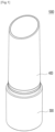
- FIG. 1 is a perspective view showing a container according to an embodiment of the present invention
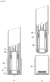
- FIG. 2 is an exploded perspective view showing the container according to the embodiment of the present invention
- FIG. 3 is a sectional view showing the container according to the embodiment of the present invention.
- a container 1000 largely includes a lifting/lowering part 100, a lifting/lowering guide part 200, a rotational part 300, and a holding part 400.
- the lifting/lowering part 100 receives a content therein, is raised or lowered according to the rotation of the rotational part 300, and thus allows the content to be exposed to the outside of the holding part 400 or received in the holding part 400.
- the lifting/lowering part 100 includes an accommodation portion 110, first guide protrusions 120 and/or a locking projection 130.
- the accommodation portion 110 is formed on an upper portion of the lifting/lowering part 100 and receives at least a portion of the content therein.
- the accommodation portion 110 is open on top thereof and has a given space for receiving the content at the inside thereof so that the lower end periphery of the content is inserted into the accommodation portion 110.
- the content is a solid or semi-solid cosmetic material applied to a user' skin.
- the content may be a lipstick, a lip gloss, a sun stick, a sun balm, a base, a foundation, and the like.
- the content may be a solid or semi-solid medical content.
- the content may not be limited thereto, and therefore, the content may include various solid or semi-solid compositions. Further, the content may include different formulations or types of cosmetics.
- the accommodation portion 110 has at least one or more first fixing protrusions 111 protruding from the inner peripheral surface thereof.
- the first fixing protrusions 111 are inserted into the outer peripheral surface of the content to prevent the content from escaping from the accommodation portion 110.
- the first fixing protrusions 111 protrude inward from the inner peripheral surface of the accommodation portion 110 in such a way as to extend by given lengths in vertical directions.
- the accommodation portion 110 has at least one or more second fixing protrusions 112 protruding from the bottom thereof.
- the second fixing protrusions 112 are inserted into the underside of the content to prevent the content from escaping from the accommodation portion 110.
- the second fixing protrusions 112 protrude upward from the bottom of the accommodation portion 110 by given lengths.
- the first guide protrusions 120 guide the lifting/lowering part 100 to allow the lifting/lowering part 100 to be lifted and lowered.
- the first guide protrusions 120 are formed under the accommodation portion 110 in such a way as to have given inclinations along the outer peripheral surface of the lifting/lowering part 100 over a range from bottom to top thereof.
- the first guide protrusions 120 move along a portion (particularly, second guide protrusions 230) of the lifting/lowering guide part 200.
- the first guide protrusions 120 guide the lifting and lowering of the lifting/lowering part 100 by means of the portion (particularly, the second guide protrusions 230) of the lifting/lowering guide part 200.
- the locking projection 130 limits the lifting and lowering heights of the lifting/lowering part 100.
- the locking projection 130 protrudes from the outer peripheral surface of the lifting/lowering part 100, and if the lifting/lowering part 100 is lifted up to a given height, the end portion of the locking projection 130 is brought into close contact with a portion (particularly, a limiting portion 420) of the holding part 400 to prevent the lifting/lowering part 100 from being lifted higher.
- the lifting/lowering guide part 200 is located to surround at least a portion of the lifting/lowering part 100 and guides the lifting and lowering of the lifting/lowering part 100.
- the lifting/lowering guide part 200 is coupled to the rotational part 300 in such a way as to be rotatable simultaneously with the rotational part 300, and if the rotational operation is applied to the rotational part 300, the lifting/lowering guide part 200 transfers the rotational force of the rotational part 300 to the lifting/lowering part 100 so that the lifting/lowering part 100 is lifted and lowered.
- a lower end of the lifting/lowering guide part 200 is detachably coupled to the rotational part 300.
- One region of the lower end (for example, side and bottom of the lifting/lowering guide part 200) of the lifting/lowering guide part 200 is exposed to the outside of the rotational part 300, and if one region exposed of the lifting/lowering guide part 200 is pressed, the lifting/lowering part 100, the lifting/lowering guide part 200 and the holding part 400 are integrally separated from the rotational part 300.
- the lifting/lowering part 100 is easily separated from the rotational part 300, and next, a lifting/lowering part 100 in which a new content is received, a lifting/lowering guide part 200, and a holding part 400 are coupled to the rotational part 300.
- the lifting/lowering guide part 200 includes a coupler 210, a first peripheral portion 220 and/or the second guide protrusions 230.
- the coupler 210 is detachably coupled to the rotational part 300. At least a portion of the coupler 210 is exposed to the outside of the rotational part 300 in such a way as to allow a user's external force to be applied thereto. As a result, the lifting/lowering part 100, the lifting/lowering guide part 200 and the holding part 400 are separated from the rotational part 300 through simple pressing against the coupler 210.
- the coupler 210 has at least one or more first locking protrusions 211 protruding from the outer peripheral surface thereof. If the rotational operation is applied to the rotational part 300, the first locking protrusions 211 allow the rotational part 300 and the lifting/lowering guide part 200 to be rotatable simultaneously.
- the first locking protrusions 211 protrude outward from the outer peripheral surface of the coupler 210 in such a way as to extend by given lengths in vertical directions.
- the first locking protrusions 211 are fastened to a portion (particularly, second locking protrusions 311) of the rotational part 300. If the rotational part 300 rotates, as a result, it rotates together with the lifting/lowering guide part 200 by means of the first locking protrusions 211 fastened to the portion 300 (particularly, the second locking protrusions 311) of the rotational part.
- the first peripheral portion 220 serves to prevent at least a portion of the outer appearance of the coupler 210 from being exposed to the outside.
- the first peripheral portion 220 serves to prevent a component (for example, the coupler 210) of the lifting/lowering guide part 200 that is coupled to the rotational part 300 from being exposed to the outside.
- the outer appearance of the refill container can be aesthetically improved.
- the first peripheral portion 220 protrudes outward from the outer peripheral surface of the lower end of the lifting/lowering guide part 200 in such a way as to allow at least a portion thereof to extend downward to surround the outer peripheral surface of the coupler 210, while being spaced apart therefrom.
- the first peripheral portion 220 is exemplary in shape, and therefore, it may have various shapes capable of performing its function.
- the first peripheral portion 220 includes a top peripheral wall 221 and a side peripheral wall 222.
- the top peripheral wall 221 transfers the external force applied to the coupler 210 to the holding part 400.
- the top peripheral wall 221 protrudes outward from the outer peripheral surface of the lower end of the lifting/lowering guide part 200. If the user's external force is applied to the coupler 210, the top peripheral wall 221 presses a portion (particularly, vertical protrusions 410) of the holding part 400 to allow the lifting/lowering guide part 200 and the holding part 400 to be integrally separated from the rotational part 300.
- the side peripheral wall 222 serves to hide at least a portion of the outer appearance of the coupler 210. To do this, the side peripheral wall 222 extends downward from the periphery of the top peripheral wall 221 in such a way as to surround the outer peripheral surface of the coupler 210.
- the side peripheral wall 222 is brought into close contact with the holding part 400 to increase a support force of the lifting/lowering guide part 200 against the holding part 400.
- the outer peripheral surface of the side peripheral wall 222 has the shape corresponding to the inner peripheral surface of a portion (particularly, a third peripheral portion 430) of the holding part 400 coming into contact with the first peripheral portion 220, so that the outer peripheral surface of the side peripheral wall 222 is brought into close contact with the inner peripheral surface of the holding part 400.
- the second guide protrusions 230 guide the lifting and lowering of the lifting/lowering part 100 if the rotational operation is applied to the rotational part 300.
- the second guide protrusions 230 are formed on the inner peripheral surface of the lifting/lowering guide part 200 in such a way as to correspond to the first guide protrusions 120. If the rotational part 300 and the lifting/lowering guide part 200 rotate simultaneously with each other by means of the user's rotational operation applied to the rotational part 300, the second guide protrusions 230 rotate, and next, the first guide protrusions 120 move along the second guide protrusions 230 so that the lifting/lowering part 100 is lifted and lowered.
- the rotational part 300 receives the user's rotational operation for lifting and lowering the lifting/lowering part 100.
- the rotational part 300 is coupled to the lower portion of the lifting/lowering guide part 200 in such a way as to be rotatable simultaneously with the lifting/lowering guide part 200, and if the user's rotational operation is applied, the lifting/lowering part 100 is lifted and lowered by means of the lifting/lowering guide part 200 rotating together with the rotational part 300.
- the rotational part 300 has an open portion 310 formed on the bottom thereof.
- the lower end portion of the lifting/lowering guide part 200 is inserted into the open portion 310.
- the coupler 210 is inserted into the open portion 310, and at least a portion of the coupler 210 is exposed to the outside through the open portion 310.
- the bottom (particularly, the coupler 210) of the lifting/lowering guide part 200 is exposed to the outside by means of the open portion 310, so that the user's pressing operation is applied to the bottom of the lifting/lowering guide part 200 to allow the lifting/lowering guide part 200 to be separated from the rotational part 300.
- the second locking protrusions 311 are formed on the inner peripheral surface of the open portion 310.
- the second locking protrusions 311 allow the rotational part 300 and the lifting/lowering guide part 200 to be rotatable simultaneously with each other.
- the second locking protrusions 311 protrude inward from the inner peripheral surface of the open portion 310 in such a way as to correspond to the first locking protrusions 211. If the coupler 210 is inserted into the open portion 310, the first locking protrusions 211 and the second locking protrusions 311 are fastened to each other, so that the rotational part 300 and the lifting/lowering guide part 200 are coupled to each other in such a way as to be rotatable simultaneously with each other.
- the rotational part 300 has a second peripheral portion 312 protruding from the underside thereof. If the coupler 210 is inserted into the open portion 310, the second peripheral portion 312 increases a coupling force between the lifting/lowering guide part 200 and the rotational part 300. For example, the second peripheral portion 312 protrudes upward from the periphery of the open portion 310, so that the second peripheral portion 312 is inserted into a downward open space between the first peripheral portion 220 and the coupler 210.
- the holding part 400 is located to surround the content, the lifting/lowering part 100 and/or the lifting/lowering guide part 200.
- the upper end portion of the holding part 400 is located on the outside of the accommodation portion 110, and the lower end portion thereof is located between the lifting/lowering guide part 200 and the rotational part 300.
- the holding part 400 is located inside the rotational part 300 to allow the rotational part 300 to be rotatable relative thereto, the holding part 400 is independent from the rotational operation of the rotational part 300, so that while the rotational part 300 is rotating, the holding part 400 is fixed, without any rotation.
- the holding part 400 is open on top thereof to allow the content lifted together with the lifting/lowering part 100, upon the lifting of the lifting/lowering part 100, to be exposed to the outside.
- the open top of the holding part 400 has a tilting surface corresponding to the tilting surface of the content.
- the holding part 400 includes the vertical protrusions 410, the limiting portion 40 and/or the third peripheral portion 430.
- the vertical protrusions 410 receive the external force applied to the coupler 210.
- the vertical protrusions 410 protrude inward from the inner peripheral surface of the holding part 400 in such a way as to come into close contact with one region of the first peripheral portion 220. If the user's external force is applied to the coupler 210, the top peripheral wall 221 presses the vertical protrusions 410 to allow the lifting/lowering guide part 200 and the holding part 400 to be integrally separated from the rotational part 300.
- the limiting portion 420 serves to limit the lifting and lowering heights of the lifting/lowering part 100.
- the limiting portion 420 protrudes inward from the inner peripheral surface of the holding part 400 so that while the lifting/lowering part 100 is lifting, the locking projection 130 comes into close contact with the limiting portion 420. In this case, the lifting/lowering part 100 is limited in being lifted higher and prevented from escaping from the holding part 400.
- the limiting portion 420 has a through hole 421. At least a portion of the lifting/lowering part 100 is inserted into the through hole 421. For example, an upper region (for example, the accommodation portion 110) of the lifting/lowering part 100 is located above the limiting portion 420, and a lower region of the lifting/lowering part 100 passes through the through hole 421 and is then located under the limiting portion 420.
- the accommodation portion 110 is located on top of the limiting portion 420, further, the underside of the accommodation portion 110 is brought into close contact with top of the limiting portion 420.
- the holding part 400 moves together with the lifting/lowering guide part 200 by means of the first peripheral portion 220, and therefore, the limiting portion 420 presses the underside of the accommodation portion 110, so that the lifting/lowering part 100 moves together with the holding part 400. That is, if the coupler 210 is pressed, the lifting/lowering part 100, the lifting/lowering guide part 200, and the holding part 400 are integrally separated from the rotational part 300.
- the through hole 421 has the shape of a non-circle
- the region of the lifting/lowering part 100 which is inserted into the through hole 421 and is lifted and lowered inside the through hole 421, has the shape of a non-circle corresponding to the shape of the through hole 421.
- the third peripheral portion 430 is brought into close contact with the lifting/lowering guide part 200 and thus increases the support force between the holding part 400 and the lifting/lowering guide part 200.
- the inner peripheral surface of the third peripheral portion 430 has the shape corresponding to the outer peripheral surface of the first peripheral portion 220 (particularly, the side peripheral wall 222)
- the third peripheral portion 430 is located on the underside of the holding part 400 in such a way as to be brought into close contact with the outer peripheral surface of the first peripheral portion 220.
- the container 1000 further includes a cover part.
- the cover part serves to surround the content and at least a portion of the holding part 400 in such a way as to be detachably coupled to the rotational part 300.
- the cover part opens or closes top of the holding part 400 in such a way as to allow the content to be exposed to the outside or prevent the content from being contaminated with foreign substances.
- the container 1000 as shown in FIGs. 1 to 3 is just exemplary, and therefore, the container 1000 may be freely configured according to embodiments of the present invention.
- the first guide protrusions 120 and the second guide protrusions 230 are changed in position to each other, and otherwise, the first locking protrusions 211 and the second locking protrusions 311 are changed in position to each other.
- such various embodiments have the same effectiveness as the above-mentioned embodiment of the present invention.
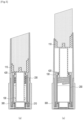
- FIG. 4 is a sectional view showing operations of the container according to the embodiment of the present invention.
- FIG. 4 shows a process in which the lifting/lowering part, the lifting/lowering guide part, and the holding part are integrally separated from the rotational part, wherein FIG. 4a is a sectional view showing the container before the separation, and FIG. 4b is a sectional view showing the container after the separation.
- the vertical protrusions 410 are pressed against the first peripheral portion 220 (particularly, the top peripheral wall 221), so that the holding part 400 moves together with the lifting/lowering guide part 200.
- the limiting portion 420 presses the underside of the accommodation portion 110 so that the lifting/lowering part 100 moves together with the holding part 400.
- the pressing operation against the exposed region of the coupler 210 allows the lifting/lowering part 100, the lifting/lowering guide part 200, and the holding part 400 to be integrally separated from the rotational part 300 and further allows a refill container having the lifting/lowering part into which a new content is received, a lifting/lowering guide part, and a holding part to be coupled to the rotational part 300. That is, it is possible that the container 1000 whose content is all consumed is refilled with the new content.
- the operations of the container 1000 as shown in FIG. 4 are just exemplary, and therefore, operations of the container 1000 may be freely performed according to embodiments of the present invention.
- FIG. 5 is a sectional view showing operations of the container according to an embodiment of the present invention.
- FIG. 5 shows a process in which the lifting/lowering part and the content received therein are lifted
- FIG. 5a is a sectional view showing the container before the lifting/lowering part is lifted
- FIG. 5b is a sectional view showing the container after the lifting/lowering part has been lifted.
- the first locking protrusions 211 are fastened to the second locking protrusions 311 to allow the lifting/lowering guide part 200 to rotate together with the rotational part 300. If the lifting/lowering guide part 200 rotates, the second guide protrusions 230 rotate, so that the first guide protrusions 120 move along the second guide protrusions 230 to allow the lifting/lowering part 100 to be lifted and lowered.
- the region of the lifting/lowering part 100 which is inserted into the through hole 421 and is lifted and lowered inside the through hole 421, has the shape of the non-circle corresponding to the non-circular shape of the through hole 421. Even if the rotational part 300 rotates, as a result, the lifting/lowering part 100 does not rotate by means of the holding part 400 fixed in rotation, so that the lifting/lowering part 100 is lifted and lowered vertically by means of the lifting/lowering guide part 200.
- the locking projection 130 is brought into close contact with the limiting portion 420, so that additional lifting of the lifting/lowering part 100 is limited to prevent the lifting/lowering part 100 from escaping from the holding part 400.
- the operations of the container 1000 as shown in FIG. 5 are just exemplary, and therefore, operations of the container 1000 may be freely performed according to embodiments of the present invention.
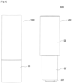
- FIG. 6 is a side view showing a set of containers according to an embodiment of the present invention.
- a set of containers 3000 includes a container 1000 and at least one refill container 2000.
- the container 1000 is the same as the container 1000 as shown in FIGs. 1 to 3 .
- the refill container 2000 includes a lifting/lowering part, a lifting/lowering guide part 200', a holding part 400', and a refill cap 500.
- the lifting/lowering part, the lifting/lowering guide part 200', and the holding part 400' are the same as the lifting/lowering part 100, the lifting/lowering guide part 200, and the holding part 400 of the container 1000.
- the refill cap 500 serves to surround at least a portion of the holding part 400' in such a way as to be detachably coupled to the holding part 400'.
- the refill cap 500 closes top of the holding part 400' in such a way as to prevent the content to be contaminated with foreign substances. If the content of the container 1000 is all consumed, the lifting/lowering part 100, the lifting/lowering guide part 200, and the holding part 400 are separated from the rotational part 300, and the refill container 2000 from which the refill cap 500 is separated is coupled to the rotational part 300 of the container 1000.
- the component (for example, the coupler 210) of the lifting/lowering guide part 200' which is coupled to the rotational part 300 of the container 1000, is not exposed to the outside.
- the outer appearance of the lifting/lowering guide part 200' can be aesthetically improved.
- the first peripheral portion 220 is not exposed to the outside of the holding part 400'. Since the first peripheral portion 220 is not exposed to the outside, it can be prevented from unintentionally rotating. That is, the lifting/lowering guide part 200' is prevented from unintentionally rotating. As a result, the lifting/lowering part of the refill container 2000 is prevented from being unintentionally lifted and lowered, and after the lifting/lowering guide part 200' and the rotational part 300 of the container 1000 are coupled to each other, the lifting/lowering part of the refill container 2000 can be lifted and lowered.
- the set of containers 3000 as shown in FIG. 6 is just exemplary, and therefore, the set of containers 3000 may be freely configured according to embodiments of the present invention.
- Second fixing protrusion 120: First guide protrusion 130: Locking projection 200, 200': Lifting/lowering guide part 210: Coupler 211: First locking protrusion 220: First peripheral portion 221: Top peripheral wall 222: Side peripheral wall 230: Second guide protrusion 300: Rotational part 310 : Open portion 311 : Second locking protrusion 312: Second peripheral portion 400, 400': Holding part 410: Vertical protrusion 320: Limiting portion 421: Through hole 430: Third peripheral portion 500: Refill cap 1000: Container 2000: Refill container 3000: Set of containers
Landscapes
- Details Of Rigid Or Semi-Rigid Containers (AREA)
- Packages (AREA)
- Glass Compositions (AREA)
Abstract
Description
- The present invention relates to a container.
- As a lot of interests in the appearances of today's people have gradually increased, a variety of cosmetics have been introduced, and among them, stick type cosmetics such as lip sticks, sun balms, and the like come into the spotlight. In the case of cosmetic containers for receiving the stick type cosmetics, however, they are thrown away, when their content is all consumed, without recycled, thereby undesirably causing waste of resources.
- To solve such problems, recently, refill products that are refilled with new contents are launched to allow their cosmetic containers to be recycled. In the case of existing refill products, however, it is inconvenient for a user to directly take and rotate or take and pull the cosmetic container, thereby lowering conveniences in operating the cosmetic container in a refill process.
- Accordingly, it is an object of the present invention to provide a container that is capable of solving such problems.
- The technical problems to be achieved through the present invention are not limited as mentioned above, and other technical problems not mentioned herein will be obviously understood by one of ordinary skill in the art through the following description.
- A container is provided according to an embodiment of the present invention. The container may include: a lifting/lowering part having an accommodation portion formed on an upper portion thereof in such a way as to receive a content therein; a lifting/lowering guide part for surrounding at least a portion of the lifting/lowering part in such a way as to guide lifting and lowering of the lifting/lowering part; a rotational part coupled to the lower portion of the lifting/lowering guide part in such a way as to be rotatable simultaneously with the lifting/lowering guide part and adapted to receive a user's rotational operation for lifting and lowering the lifting/lowering part; and a holding part having an upper end portion located on the outside of the accommodation portion and a lower end portion located between the rotational part and the lifting/lowering guide part in such a way as to allow the rotational part to be rotatable relative thereto, wherein a lower end of the lifting/lowering guide part is detachably coupled to the rotational part, and if one region of the lower end of the lifting/lowering guide part, which is exposed to the outside of the
rotational part 300, is pressed, the lifting/lowering part, the lifting/lowering guide part and the holding part are integrally separated from the rotational part. - According to the present invention, the container is configured to allow one region of the lower end of the lifting/lowering guide part to be exposed to the outside of the rotational part, so that the lifting/lowering part, the lifting/lowering guide part and the holding part are separated easily from the rotational part through simple pressing against the lifting/lowering guide part.
- According to the present invention, further, the container is configured to have the component of the refill container coupled to the rotational part, which is not exposed to the outside, thereby aesthetically improving the outer appearance of the refill container.
- According to the present invention, furthermore, the container is configured to allow the lifting/lowering part to be lifted and lowered through the rotation of the rotational part in the state where the lifting/lowering guide part is coupled to the rotational part and to have the first peripheral portion of the lifting/lowering guide part of the refill container not exposed to the outside, thereby preventing the lifting/lowering guide part from unintentionally rotating and the lifting/lowering part from being unintentionally lifted and lowered.
- To allow the drawings as will be mentioned in the description of the present invention to be more sufficiently understood, the brief description of the drawings may be provided.
-
FIG. 1 is a perspective view showing a container according to an embodiment of the present invention. -
FIG. 2 is an exploded perspective view showing the container according to the embodiment of the present invention. -
FIG. 3 is a sectional view showing the container according to the embodiment of the present invention. -
FIG. 4 is a sectional view showing operations of the container according to the embodiment of the present invention. -
FIG. 5 is a sectional view showing operations of the container according to an embodiment of the present invention. -
FIG. 6 is a side view showing a set of containers according to the embodiment of the present invention. - A container is provided according to an embodiment of the present invention. The container may include: a lifting/lowering part having an accommodation portion formed on an upper portion thereof in such a way as to receive a content therein; a lifting/lowering guide part for surrounding at least a portion of the lifting/lowering part in such a way as to guide lifting and lowering of the lifting/lowering part; a rotational part coupled to the lower portion of the lifting/lowering guide part in such a way as to be rotatable simultaneously with the lifting/lowering guide part and adapted to receive a user's rotational operation for lifting and lowering the lifting/lowering part; and a holding part having an upper end portion located on the outside of the accommodation portion and a lower end portion located between the rotational part and the lifting/lowering guide part in such a way as to allow the rotational part to be rotatable relative thereto, wherein a lower end of the lifting/lowering guide part is detachably coupled to the rotational part, and if one region of the lower end of the lifting/lowering guide part, which is exposed to the outside of the
rotational part 300, is pressed, the lifting/lowering part, the lifting/lowering guide part and the holding part are integrally separated from the rotational part. - Further, the rotational part may have an open portion formed on the bottom thereof in such a way as to insert the lower end of the lifting/lowering guide part thereinto, and the underside of the lifting/lowering guide part may be exposed to the outside by means of the open portion so that the pressing may be applied thereto.
- Furthermore, the lifting/lowering guide part may include: a coupler inserted into the open portion of the rotational part in such a way as to allow at least a portion thereof to be exposed to the outside; and a first peripheral portion protruding outward from the outer peripheral surface of the lower end of the lifting/lowering guide part in such a way as to allow at least a portion thereof to extend downward to surround the outer peripheral surface of the coupler, while being spaced apart therefrom.
- Besides, the coupler may have at least one or more first locking protrusions protruding from the outer peripheral surface thereof, and the open portion may have at least one or more second locking protrusions protruding from the inner peripheral surface thereof, so that as the first locking protrusions are fastened to the second locking protrusions, the rotational part and the lifting/lowering guide part may be coupled to be rotatable simultaneously with each other.
- Further, the first peripheral portion may include: a top peripheral wall protruding outward from the outer peripheral surface of the lower end of the lifting/lowering guide part; and a side peripheral wall extending downward from the periphery of the top peripheral wall in such a way as to surround the outer peripheral surface of the coupler, and the holding part may have at least one or more vertical protrusions protruding inward from the inner peripheral surface thereof, so that if the coupler is pressed, the vertical protrusions may be pressed against the top peripheral wall to allow the lifting/lowering guide part and the holding part to be integrally separated from the rotational part.
- Furthermore, the rotational part may have a second peripheral portion protruding upward from the periphery of the open portion in such a way as to be inserted into a downward open space between the first peripheral portion and the coupler.
- Besides, the holding part may have a third peripheral portion located on the underside thereof to the shape corresponding to the outer peripheral surface of the first peripheral portion in such a way as to be brought into close contact with the outer peripheral surface of the first peripheral portion.
- Moreover, the lifting/lowering part may have at least one or more first guide protrusions on the outer peripheral surface thereof under the accommodation portion, and the lifting/lowering guide part may have at least one or more second guide protrusions on the inner peripheral surface thereof, so that if the rotational part rotates, the first guide protrusions may move along the second guide protrusions to allow the lifting/lowering part to be lifted and lowered.
- Further, the lifting/lowering part may include a locking projection on the outer peripheral surface thereof, and the holding part may include a limiting portion with a through hole into which at least a portion of the lifting/lowering part is inserted, so that if the lifting/lowering part is lifted to cause the locking projection to be brought into close contact with the limiting portion, additional lifting of the lifting/lowering part may be limited to prevent the lifting/lowering part from escaping from the holding part.
- Hereinafter, example embodiments will be described with reference to the accompanying drawings. In addition, a device of the present invention and a method for using the device will be explained in detail with reference to the attached drawings. In the drawings, the same reference numerals or symbols are parts or components performing the same functions. Further, top, bottom, left and right directions as will be described below are determined with reference to the drawings, and accordingly, the scope of the present invention is not necessarily restricted to the corresponding directions.
- Terms, such as the first, the second, and the like, may be used to describe various elements, but the elements should not be restricted by the terms. The terms are used to only distinguish one element from the other element. For example, a first element may be named a second element without departing from the scope of the present invention. Likewise, a second element may be named a first element. A term 'and/or' includes a combination of a plurality of relevant and described items or any one of a plurality of related and described items.
- Terms used in this application are used to only describe specific exemplary embodiments and are not intended to restrict the present invention. An expression referencing a singular value additionally refers to a corresponding expression of the plural number, unless explicitly limited otherwise by the context. In this application, terms, such as "comprise", "include", or "have", are intended to designate those characteristics, numbers, steps, operations, elements, or parts which are described in the specification, or any combination of them that exist, and it should be understood that they do not preclude the possibility of the existence or possible addition of one or more additional characteristics, numbers, steps, operations, elements, or parts, or combinations thereof.
- In the description, when it is said that one element is described as being "connected" to the other element, one element may be directly connected or coupled to the other element, but it should be understood that another element may be present between the two elements. When it is said that one portion is described as "includes" any component, further, one element may further include other components unless no specific description is suggested.
-
FIG. 1 is a perspective view showing a container according to an embodiment of the present invention,FIG. 2 is an exploded perspective view showing the container according to the embodiment of the present invention, andFIG. 3 is a sectional view showing the container according to the embodiment of the present invention. - Referring to
FIGs. 1 to 3 , acontainer 1000 according to an embodiment of the present invention largely includes a lifting/loweringpart 100, a lifting/loweringguide part 200, arotational part 300, and aholding part 400. - The lifting/lowering
part 100 receives a content therein, is raised or lowered according to the rotation of therotational part 300, and thus allows the content to be exposed to the outside of theholding part 400 or received in theholding part 400. - According to the embodiment of the present invention, the lifting/lowering
part 100 includes anaccommodation portion 110,first guide protrusions 120 and/or alocking projection 130. - The
accommodation portion 110 is formed on an upper portion of the lifting/loweringpart 100 and receives at least a portion of the content therein. For example, theaccommodation portion 110 is open on top thereof and has a given space for receiving the content at the inside thereof so that the lower end periphery of the content is inserted into theaccommodation portion 110. In this case, the content is a solid or semi-solid cosmetic material applied to a user' skin. For example, the content may be a lipstick, a lip gloss, a sun stick, a sun balm, a base, a foundation, and the like. Further, the content may be a solid or semi-solid medical content. However, the content may not be limited thereto, and therefore, the content may include various solid or semi-solid compositions. Further, the content may include different formulations or types of cosmetics. - According to the embodiment of the present invention, the
accommodation portion 110 has at least one or morefirst fixing protrusions 111 protruding from the inner peripheral surface thereof. Thefirst fixing protrusions 111 are inserted into the outer peripheral surface of the content to prevent the content from escaping from theaccommodation portion 110. To do this, thefirst fixing protrusions 111 protrude inward from the inner peripheral surface of theaccommodation portion 110 in such a way as to extend by given lengths in vertical directions. - According to the embodiment of the present invention, the
accommodation portion 110 has at least one or more second fixingprotrusions 112 protruding from the bottom thereof. The second fixingprotrusions 112 are inserted into the underside of the content to prevent the content from escaping from theaccommodation portion 110. For example, the second fixingprotrusions 112 protrude upward from the bottom of theaccommodation portion 110 by given lengths. - If a rotational operation is applied to the
rotational part 300, thefirst guide protrusions 120 guide the lifting/loweringpart 100 to allow the lifting/loweringpart 100 to be lifted and lowered. For example, thefirst guide protrusions 120 are formed under theaccommodation portion 110 in such a way as to have given inclinations along the outer peripheral surface of the lifting/loweringpart 100 over a range from bottom to top thereof. Thefirst guide protrusions 120 move along a portion (particularly, second guide protrusions 230) of the lifting/loweringguide part 200. If the lifting/loweringguide part 200 rotates according to the rotational operation of therotational part 300, thefirst guide protrusions 120 guide the lifting and lowering of the lifting/loweringpart 100 by means of the portion (particularly, the second guide protrusions 230) of the lifting/loweringguide part 200. - The locking
projection 130 limits the lifting and lowering heights of the lifting/loweringpart 100. For example, the lockingprojection 130 protrudes from the outer peripheral surface of the lifting/loweringpart 100, and if the lifting/loweringpart 100 is lifted up to a given height, the end portion of the lockingprojection 130 is brought into close contact with a portion (particularly, a limiting portion 420) of the holdingpart 400 to prevent the lifting/loweringpart 100 from being lifted higher. - The lifting/lowering
guide part 200 is located to surround at least a portion of the lifting/loweringpart 100 and guides the lifting and lowering of the lifting/loweringpart 100. In detail, the lifting/loweringguide part 200 is coupled to therotational part 300 in such a way as to be rotatable simultaneously with therotational part 300, and if the rotational operation is applied to therotational part 300, the lifting/loweringguide part 200 transfers the rotational force of therotational part 300 to the lifting/loweringpart 100 so that the lifting/loweringpart 100 is lifted and lowered. - According to the embodiment of the present invention, a lower end of the lifting/lowering
guide part 200 is detachably coupled to therotational part 300. One region of the lower end (for example, side and bottom of the lifting/lowering guide part 200) of the lifting/loweringguide part 200 is exposed to the outside of therotational part 300, and if one region exposed of the lifting/loweringguide part 200 is pressed, the lifting/loweringpart 100, the lifting/loweringguide part 200 and the holdingpart 400 are integrally separated from therotational part 300. If the content received in the lifting/loweringpart 100 is consumed, therefore, the lifting/loweringpart 100 is easily separated from therotational part 300, and next, a lifting/loweringpart 100 in which a new content is received, a lifting/loweringguide part 200, and a holdingpart 400 are coupled to therotational part 300. - According to the embodiment of the present invention, the lifting/lowering
guide part 200 includes acoupler 210, a firstperipheral portion 220 and/or thesecond guide protrusions 230. - The
coupler 210 is detachably coupled to therotational part 300. At least a portion of thecoupler 210 is exposed to the outside of therotational part 300 in such a way as to allow a user's external force to be applied thereto. As a result, the lifting/loweringpart 100, the lifting/loweringguide part 200 and the holdingpart 400 are separated from therotational part 300 through simple pressing against thecoupler 210. - According to the embodiment of the present invention, the
coupler 210 has at least one or more first lockingprotrusions 211 protruding from the outer peripheral surface thereof. If the rotational operation is applied to therotational part 300, the first lockingprotrusions 211 allow therotational part 300 and the lifting/loweringguide part 200 to be rotatable simultaneously. For example, the first lockingprotrusions 211 protrude outward from the outer peripheral surface of thecoupler 210 in such a way as to extend by given lengths in vertical directions. Thefirst locking protrusions 211 are fastened to a portion (particularly, second locking protrusions 311) of therotational part 300. If therotational part 300 rotates, as a result, it rotates together with the lifting/loweringguide part 200 by means of the first lockingprotrusions 211 fastened to the portion 300 (particularly, the second locking protrusions 311) of the rotational part. - The first
peripheral portion 220 serves to prevent at least a portion of the outer appearance of thecoupler 210 from being exposed to the outside. In detail, in the case of a refill container having acontainer part 100 in which a new content is received, a lifting/loweringguide part 200, and a holdingpart 400, the firstperipheral portion 220 serves to prevent a component (for example, the coupler 210) of the lifting/loweringguide part 200 that is coupled to therotational part 300 from being exposed to the outside. As a result, the outer appearance of the refill container can be aesthetically improved. To do this, the firstperipheral portion 220 protrudes outward from the outer peripheral surface of the lower end of the lifting/loweringguide part 200 in such a way as to allow at least a portion thereof to extend downward to surround the outer peripheral surface of thecoupler 210, while being spaced apart therefrom. However, the firstperipheral portion 220 is exemplary in shape, and therefore, it may have various shapes capable of performing its function. - According to the embodiment of the present invention, the first
peripheral portion 220 includes a topperipheral wall 221 and a sideperipheral wall 222. - The top
peripheral wall 221 transfers the external force applied to thecoupler 210 to the holdingpart 400. For example, the topperipheral wall 221 protrudes outward from the outer peripheral surface of the lower end of the lifting/loweringguide part 200. If the user's external force is applied to thecoupler 210, the topperipheral wall 221 presses a portion (particularly, vertical protrusions 410) of the holdingpart 400 to allow the lifting/loweringguide part 200 and the holdingpart 400 to be integrally separated from therotational part 300. - The side
peripheral wall 222 serves to hide at least a portion of the outer appearance of thecoupler 210. To do this, the sideperipheral wall 222 extends downward from the periphery of the topperipheral wall 221 in such a way as to surround the outer peripheral surface of thecoupler 210. - Further, the side
peripheral wall 222 is brought into close contact with the holdingpart 400 to increase a support force of the lifting/loweringguide part 200 against the holdingpart 400. For example, the outer peripheral surface of the sideperipheral wall 222 has the shape corresponding to the inner peripheral surface of a portion (particularly, a third peripheral portion 430) of the holdingpart 400 coming into contact with the firstperipheral portion 220, so that the outer peripheral surface of the sideperipheral wall 222 is brought into close contact with the inner peripheral surface of the holdingpart 400. - The
second guide protrusions 230 guide the lifting and lowering of the lifting/loweringpart 100 if the rotational operation is applied to therotational part 300. For example, thesecond guide protrusions 230 are formed on the inner peripheral surface of the lifting/loweringguide part 200 in such a way as to correspond to thefirst guide protrusions 120. If therotational part 300 and the lifting/loweringguide part 200 rotate simultaneously with each other by means of the user's rotational operation applied to therotational part 300, thesecond guide protrusions 230 rotate, and next, thefirst guide protrusions 120 move along thesecond guide protrusions 230 so that the lifting/loweringpart 100 is lifted and lowered. - The
rotational part 300 receives the user's rotational operation for lifting and lowering the lifting/loweringpart 100. For example, therotational part 300 is coupled to the lower portion of the lifting/loweringguide part 200 in such a way as to be rotatable simultaneously with the lifting/loweringguide part 200, and if the user's rotational operation is applied, the lifting/loweringpart 100 is lifted and lowered by means of the lifting/loweringguide part 200 rotating together with therotational part 300. - According to the embodiment of the present invention, the
rotational part 300 has anopen portion 310 formed on the bottom thereof. The lower end portion of the lifting/loweringguide part 200 is inserted into theopen portion 310. In detail, thecoupler 210 is inserted into theopen portion 310, and at least a portion of thecoupler 210 is exposed to the outside through theopen portion 310. The bottom (particularly, the coupler 210) of the lifting/loweringguide part 200 is exposed to the outside by means of theopen portion 310, so that the user's pressing operation is applied to the bottom of the lifting/loweringguide part 200 to allow the lifting/loweringguide part 200 to be separated from therotational part 300. - According to the embodiment of the present invention, the second locking
protrusions 311 are formed on the inner peripheral surface of theopen portion 310. Thesecond locking protrusions 311 allow therotational part 300 and the lifting/loweringguide part 200 to be rotatable simultaneously with each other. For example, the second lockingprotrusions 311 protrude inward from the inner peripheral surface of theopen portion 310 in such a way as to correspond to thefirst locking protrusions 211. If thecoupler 210 is inserted into theopen portion 310, the first lockingprotrusions 211 and the second lockingprotrusions 311 are fastened to each other, so that therotational part 300 and the lifting/loweringguide part 200 are coupled to each other in such a way as to be rotatable simultaneously with each other. - The
rotational part 300 has a secondperipheral portion 312 protruding from the underside thereof. If thecoupler 210 is inserted into theopen portion 310, the secondperipheral portion 312 increases a coupling force between the lifting/loweringguide part 200 and therotational part 300. For example, the secondperipheral portion 312 protrudes upward from the periphery of theopen portion 310, so that the secondperipheral portion 312 is inserted into a downward open space between the firstperipheral portion 220 and thecoupler 210. - The holding
part 400 is located to surround the content, the lifting/loweringpart 100 and/or the lifting/loweringguide part 200. For example, the upper end portion of the holdingpart 400 is located on the outside of theaccommodation portion 110, and the lower end portion thereof is located between the lifting/loweringguide part 200 and therotational part 300. Further, since the holdingpart 400 is located inside therotational part 300 to allow therotational part 300 to be rotatable relative thereto, the holdingpart 400 is independent from the rotational operation of therotational part 300, so that while therotational part 300 is rotating, the holdingpart 400 is fixed, without any rotation. - According to the embodiment of the present invention, the holding
part 400 is open on top thereof to allow the content lifted together with the lifting/loweringpart 100, upon the lifting of the lifting/loweringpart 100, to be exposed to the outside. For example, if the top end of the content tilts to allow the content to be effectively applied to the user's skin, the open top of the holdingpart 400 has a tilting surface corresponding to the tilting surface of the content. - According to the embodiment of the present invention, the holding
part 400 includes thevertical protrusions 410, the limiting portion 40 and/or the thirdperipheral portion 430. - The
vertical protrusions 410 receive the external force applied to thecoupler 210. For example, thevertical protrusions 410 protrude inward from the inner peripheral surface of the holdingpart 400 in such a way as to come into close contact with one region of the firstperipheral portion 220. If the user's external force is applied to thecoupler 210, the topperipheral wall 221 presses thevertical protrusions 410 to allow the lifting/loweringguide part 200 and the holdingpart 400 to be integrally separated from therotational part 300. - The limiting
portion 420 serves to limit the lifting and lowering heights of the lifting/loweringpart 100. For example, the limitingportion 420 protrudes inward from the inner peripheral surface of the holdingpart 400 so that while the lifting/loweringpart 100 is lifting, the lockingprojection 130 comes into close contact with the limitingportion 420. In this case, the lifting/loweringpart 100 is limited in being lifted higher and prevented from escaping from the holdingpart 400. - According to the embodiment of the present invention, the limiting
portion 420 has a throughhole 421. At least a portion of the lifting/loweringpart 100 is inserted into the throughhole 421. For example, an upper region (for example, the accommodation portion 110) of the lifting/loweringpart 100 is located above the limitingportion 420, and a lower region of the lifting/loweringpart 100 passes through the throughhole 421 and is then located under the limitingportion 420. - If the
accommodation portion 110 is located on top of the limitingportion 420, further, the underside of theaccommodation portion 110 is brought into close contact with top of the limitingportion 420. In this case, if the user's external force is applied to thecoupler 210, the holdingpart 400 moves together with the lifting/loweringguide part 200 by means of the firstperipheral portion 220, and therefore, the limitingportion 420 presses the underside of theaccommodation portion 110, so that the lifting/loweringpart 100 moves together with the holdingpart 400. That is, if thecoupler 210 is pressed, the lifting/loweringpart 100, the lifting/loweringguide part 200, and the holdingpart 400 are integrally separated from therotational part 300. - According to the embodiment of the present invention, the through
hole 421 has the shape of a non-circle, and the region of the lifting/loweringpart 100, which is inserted into the throughhole 421 and is lifted and lowered inside the throughhole 421, has the shape of a non-circle corresponding to the shape of the throughhole 421. Even if therotational part 300 rotates, as a result, the lifting/loweringpart 100 does not rotate by means of the holdingpart 400 fixed in rotation, so that the lifting/loweringpart 100 is lifted and lowered vertically by means of the lifting/loweringguide part 200. - The third
peripheral portion 430 is brought into close contact with the lifting/loweringguide part 200 and thus increases the support force between the holdingpart 400 and the lifting/loweringguide part 200. For example, while the inner peripheral surface of the thirdperipheral portion 430 has the shape corresponding to the outer peripheral surface of the first peripheral portion 220 (particularly, the side peripheral wall 222), the thirdperipheral portion 430 is located on the underside of the holdingpart 400 in such a way as to be brought into close contact with the outer peripheral surface of the firstperipheral portion 220. - According to the embodiment of the present invention, the
container 1000 further includes a cover part. The cover part serves to surround the content and at least a portion of the holdingpart 400 in such a way as to be detachably coupled to therotational part 300. The cover part opens or closes top of the holdingpart 400 in such a way as to allow the content to be exposed to the outside or prevent the content from being contaminated with foreign substances. - The
container 1000 as shown inFIGs. 1 to 3 is just exemplary, and therefore, thecontainer 1000 may be freely configured according to embodiments of the present invention. For example, thefirst guide protrusions 120 and thesecond guide protrusions 230 are changed in position to each other, and otherwise, the first lockingprotrusions 211 and the second lockingprotrusions 311 are changed in position to each other. In this case, it is obvious that such various embodiments have the same effectiveness as the above-mentioned embodiment of the present invention. -
FIG. 4 is a sectional view showing operations of the container according to the embodiment of the present invention. In detail,FIG. 4 shows a process in which the lifting/lowering part, the lifting/lowering guide part, and the holding part are integrally separated from the rotational part, whereinFIG. 4a is a sectional view showing the container before the separation, andFIG. 4b is a sectional view showing the container after the separation. - Referring to
FIG. 4 , if the underside of thecoupler 210, which is exposed to the outside through theopen portion 310 of therotational part 300, is pressed, thevertical protrusions 410 are pressed against the first peripheral portion 220 (particularly, the top peripheral wall 221), so that the holdingpart 400 moves together with the lifting/loweringguide part 200. Further, the limitingportion 420 presses the underside of theaccommodation portion 110 so that the lifting/loweringpart 100 moves together with the holdingpart 400. - Like this, the pressing operation against the exposed region of the
coupler 210 allows the lifting/loweringpart 100, the lifting/loweringguide part 200, and the holdingpart 400 to be integrally separated from therotational part 300 and further allows a refill container having the lifting/lowering part into which a new content is received, a lifting/lowering guide part, and a holding part to be coupled to therotational part 300. That is, it is possible that thecontainer 1000 whose content is all consumed is refilled with the new content. - The operations of the
container 1000 as shown inFIG. 4 are just exemplary, and therefore, operations of thecontainer 1000 may be freely performed according to embodiments of the present invention. -
FIG. 5 is a sectional view showing operations of the container according to an embodiment of the present invention. In detail,FIG. 5 shows a process in which the lifting/lowering part and the content received therein are lifted, whereinFIG. 5a is a sectional view showing the container before the lifting/lowering part is lifted, andFIG. 5b is a sectional view showing the container after the lifting/lowering part has been lifted. - Referring to
FIG. 5 , if the user's rotational operation is applied to therotational part 300, the first lockingprotrusions 211 are fastened to the second lockingprotrusions 311 to allow the lifting/loweringguide part 200 to rotate together with therotational part 300. If the lifting/loweringguide part 200 rotates, thesecond guide protrusions 230 rotate, so that thefirst guide protrusions 120 move along thesecond guide protrusions 230 to allow the lifting/loweringpart 100 to be lifted and lowered. - In this case, the region of the lifting/lowering
part 100, which is inserted into the throughhole 421 and is lifted and lowered inside the throughhole 421, has the shape of the non-circle corresponding to the non-circular shape of the throughhole 421. Even if therotational part 300 rotates, as a result, the lifting/loweringpart 100 does not rotate by means of the holdingpart 400 fixed in rotation, so that the lifting/loweringpart 100 is lifted and lowered vertically by means of the lifting/loweringguide part 200. - After that, if the lifting/lowering
part 100 is lifted up to a given height, the lockingprojection 130 is brought into close contact with the limitingportion 420, so that additional lifting of the lifting/loweringpart 100 is limited to prevent the lifting/loweringpart 100 from escaping from the holdingpart 400. - The operations of the
container 1000 as shown inFIG. 5 are just exemplary, and therefore, operations of thecontainer 1000 may be freely performed according to embodiments of the present invention. -
FIG. 6 is a side view showing a set of containers according to an embodiment of the present invention. - Referring to
FIG. 6 , a set ofcontainers 3000 includes acontainer 1000 and at least onerefill container 2000. In this case, thecontainer 1000 is the same as thecontainer 1000 as shown inFIGs. 1 to 3 . - The
refill container 2000 includes a lifting/lowering part, a lifting/lowering guide part 200', a holding part 400', and arefill cap 500. In this case, the lifting/lowering part, the lifting/lowering guide part 200', and the holding part 400' are the same as the lifting/loweringpart 100, the lifting/loweringguide part 200, and the holdingpart 400 of thecontainer 1000. - The
refill cap 500 serves to surround at least a portion of the holding part 400' in such a way as to be detachably coupled to the holding part 400'. Therefill cap 500 closes top of the holding part 400' in such a way as to prevent the content to be contaminated with foreign substances. If the content of thecontainer 1000 is all consumed, the lifting/loweringpart 100, the lifting/loweringguide part 200, and the holdingpart 400 are separated from therotational part 300, and therefill container 2000 from which therefill cap 500 is separated is coupled to therotational part 300 of thecontainer 1000. - According to the embodiment of the present invention, in the case of the
refill container 2000, the component (for example, the coupler 210) of the lifting/lowering guide part 200', which is coupled to therotational part 300 of thecontainer 1000, is not exposed to the outside. As a result, the outer appearance of the lifting/lowering guide part 200' can be aesthetically improved. - According to the embodiment of the present invention, in the case of the
refill container 2000, the firstperipheral portion 220 is not exposed to the outside of the holding part 400'. Since the firstperipheral portion 220 is not exposed to the outside, it can be prevented from unintentionally rotating. That is, the lifting/lowering guide part 200' is prevented from unintentionally rotating. As a result, the lifting/lowering part of therefill container 2000 is prevented from being unintentionally lifted and lowered, and after the lifting/lowering guide part 200' and therotational part 300 of thecontainer 1000 are coupled to each other, the lifting/lowering part of therefill container 2000 can be lifted and lowered. - The set of
containers 3000 as shown inFIG. 6 is just exemplary, and therefore, the set ofcontainers 3000 may be freely configured according to embodiments of the present invention. - As mentioned above, the preferred embodiment of the present invention has been disclosed in the specification and drawings. Therefore, persons skilled in the relevant art can appreciate that many modifications and variations are possible in light of the above teachings. It is therefore intended that the scope of the invention be limited not by this detailed description, but rather by the claims appended hereto.
100: Lifting/lowering part 110: Accommodation portion 111: First fixing protrusion 112: Second fixing protrusion 120: First guide protrusion 130: Locking projection 200, 200': Lifting/lowering guide part 210: Coupler 211: First locking protrusion 220: First peripheral portion 221: Top peripheral wall 222: Side peripheral wall 230: Second guide protrusion 300: Rotational part 310 : Open portion 311 : Second locking protrusion 312: Second peripheral portion 400, 400': Holding part 410: Vertical protrusion 320: Limiting portion 421: Through hole 430: Third peripheral portion 500: Refill cap 1000: Container 2000: Refill container 3000: Set of containers
Claims (9)
- A container comprising:a lifting/lowering part having an accommodation portion formed on an upper portion thereof in such a way as to receive a content therein;a lifting/lowering guide part for surrounding at least a portion of the lifting/lowering part in such a way as to guide lifting and lowering of the lifting/lowering part;a rotational part coupled to the lower portion of the lifting/lowering guide part in such a way as to be rotatable simultaneously with the lifting/lowering guide part and adapted to receive a user's rotational operation for lifting and lowering the lifting/lowering part; anda holding part having an upper end portion located on the outside of the accommodation portion and a lower end portion located between the rotational part and the lifting/lowering guide part in such a way as to allow the rotational part to be rotatable relative thereto,wherein a lower end of the lifting/lowering guide part is detachably coupled to the rotational part, and if one region of the lower end of the lifting/lowering guide part, which is exposed to the outside of the rotational part, is pressed, the lifting/lowering part, the lifting/lowering guide part and the holding part are integrally separated from the rotational part.
- The container according to claim 1, wherein the rotational part has an open portion formed on the bottom thereof in such a way as to insert the lower end of the lifting/lowering guide part thereinto, and the underside of the lifting/lowering guide part is exposed to the outside by means of the open portion so that the pressing is applied thereto.
- The container according to claim 2, wherein the lifting/lowering guide part comprises:a coupler inserted into the open portion of the rotational part in such a way as to allow at least a portion thereof to be exposed to the outside; anda first peripheral portion protruding outward from the outer peripheral surface of the lower end of the lifting/lowering guide part in such a way as to allow at least a portion thereof to extend downward to surround the outer peripheral surface of the coupler, while being spaced apart therefrom.
- The container according to claim 3, wherein the coupler has at least one or more first locking protrusions protruding from the outer peripheral surface thereof, and the open portion has at least one or more second locking protrusions protruding from the inner peripheral surface thereof, so that as the first locking protrusions are fastened to the second locking protrusions, the rotational part and the lifting/lowering guide part are coupled to be rotatable simultaneously with each other.
- The container according to claim 3, wherein the first peripheral portion comprises: a top peripheral wall protruding outward from the outer peripheral surface of the lower end of the lifting/lowering guide part; and a side peripheral wall extending downward from the periphery of the top peripheral wall in such a way as to surround the outer peripheral surface of the coupler, and the holding part has at least one or more vertical protrusions protruding inward from the inner peripheral surface thereof, so that if the coupler is pressed, the vertical protrusions are pressed against the top peripheral wall to allow the lifting/lowering guide part and the holding part to be integrally separated from the rotational part.
- The container according to claim 3, wherein the rotational part has a second peripheral portion protruding upward from the periphery of the open portion in such a way as to be inserted into a downward open space between the first peripheral portion and the coupler.
- The container according to claim 3, wherein the holding part has a third peripheral portion located on the underside thereof to the shape corresponding to the outer peripheral surface of the first peripheral portion in such a way as to be brought into close contact with the outer peripheral surface of the first peripheral portion.
- The container according to claim 1, wherein the lifting/lowering part has at least one or more first guide protrusions on the outer peripheral surface thereof under the accommodation portion, and the lifting/lowering guide part has at least one or more second guide protrusions on the inner peripheral surface thereof, so that if the rotational part rotates, the first guide protrusions move along the second guide protrusions to allow the lifting/lowering part to be lifted and lowered.
- The container according to claim 1, wherein the lifting/lowering part comprises a locking projection on the outer peripheral surface thereof, and the holding part comprises a limiting portion with a through hole into which at least a portion of the lifting/lowering part is inserted, so that if the lifting/lowering part is lifted to cause the locking projection to be brought into close contact with the limiting portion, additional lifting of the lifting/lowering part is limited to prevent the lifting/lowering part from escaping from the holding part.
Applications Claiming Priority (2)
| Application Number | Priority Date | Filing Date | Title |
|---|---|---|---|
| KR1020220110912A KR102619824B1 (en) | 2022-09-01 | 2022-09-01 | Container |
| PCT/KR2023/007748 WO2024048924A1 (en) | 2022-09-01 | 2023-06-07 | Contents container |
Publications (2)
| Publication Number | Publication Date |
|---|---|
| EP4555895A1 true EP4555895A1 (en) | 2025-05-21 |
| EP4555895A4 EP4555895A4 (en) | 2025-10-22 |
Family
ID=89538747
Family Applications (1)
| Application Number | Title | Priority Date | Filing Date |
|---|---|---|---|
| EP23860610.7A Pending EP4555895A4 (en) | 2022-09-01 | 2023-06-07 | CONTENTS CONTAINER |
Country Status (6)
| Country | Link |
|---|---|
| US (1) | US20260053258A1 (en) |
| EP (1) | EP4555895A4 (en) |
| JP (1) | JP2025526889A (en) |
| KR (1) | KR102619824B1 (en) |
| CN (1) | CN119630310A (en) |
| WO (1) | WO2024048924A1 (en) |
Families Citing this family (3)
| Publication number | Priority date | Publication date | Assignee | Title |
|---|---|---|---|---|
| US20250288504A1 (en) * | 2024-03-18 | 2025-09-18 | Tilt Beauty, LLC | Replaceable solid cosmetic dispenser |
| KR102946328B1 (en) * | 2024-07-02 | 2026-04-01 | 주식회사 정훈 | Lipstick container equipped with a removable protective tube |
| KR102944539B1 (en) * | 2025-12-12 | 2026-03-25 | 이성환 | Stick-type container |
Family Cites Families (7)
| Publication number | Priority date | Publication date | Assignee | Title |
|---|---|---|---|---|
| JPS6131312U (en) * | 1984-07-30 | 1986-02-25 | 株式会社 飛弾製作所 | bar cosmetic container |
| KR102182456B1 (en) * | 2019-01-17 | 2020-11-24 | 펌텍코리아(주) | Lipstick case with convenient refill structure |
| KR102270689B1 (en) * | 2019-07-09 | 2021-06-28 | 함형길 | A refillable stick-type cosmetic vessel |
| KR200493142Y1 (en) * | 2019-11-25 | 2021-02-08 | 주식회사 리치코스 | Lipstick tube |
| US11297925B2 (en) * | 2020-08-10 | 2022-04-12 | Crystal International (Group) | Refillable lipstick case |
| KR102371335B1 (en) * | 2021-11-15 | 2022-03-08 | 주식회사 정민 | Refill type stick faundation vessel |
| KR102389856B1 (en) * | 2022-03-11 | 2022-04-28 | 주식회사 씨티케이 | Stick type cosmetic container |
-
2022
- 2022-09-01 KR KR1020220110912A patent/KR102619824B1/en active Active
-
2023
- 2023-06-07 JP JP2025508819A patent/JP2025526889A/en active Pending
- 2023-06-07 WO PCT/KR2023/007748 patent/WO2024048924A1/en not_active Ceased
- 2023-06-07 US US19/104,949 patent/US20260053258A1/en active Pending
- 2023-06-07 EP EP23860610.7A patent/EP4555895A4/en active Pending
- 2023-06-07 CN CN202380057381.4A patent/CN119630310A/en active Pending
Also Published As
| Publication number | Publication date |
|---|---|
| JP2025526889A (en) | 2025-08-15 |
| WO2024048924A1 (en) | 2024-03-07 |
| EP4555895A4 (en) | 2025-10-22 |
| US20260053258A1 (en) | 2026-02-26 |
| CN119630310A (en) | 2025-03-14 |
| KR102619824B1 (en) | 2024-01-03 |
Similar Documents
| Publication | Publication Date | Title |
|---|---|---|
| US20260053258A1 (en) | Contents container | |
| KR102377557B1 (en) | Stick content container | |
| KR102368145B1 (en) | Stick content container | |
| EP3632261B1 (en) | Stick-type cosmetic material container having side button | |
| KR101503239B1 (en) | The container containing different kinds of contents | |
| KR102011701B1 (en) | A button retractable typed container | |
| KR101859186B1 (en) | Stick type cosmetic vessel containing different kinds of contents | |
| KR20220069500A (en) | Stick type cosmetic container | |
| KR102265177B1 (en) | A spuit-typed cosmetic container | |
| KR102196810B1 (en) | Stick type cosmetic container | |
| KR102395106B1 (en) | Cosmetic vessel | |
| KR20230047683A (en) | Stick type cosmetic container | |
| KR200487975Y1 (en) | Cosmetic vessel | |
| JP7698798B2 (en) | contents container | |
| KR102290356B1 (en) | Retractable container | |
| KR101807294B1 (en) | Vessel with a dual applicator | |
| KR20180006204A (en) | Lipgloss case | |
| CN222692919U (en) | Stick-shaped container | |
| KR102911503B1 (en) | Stick content container | |
| KR200493235Y1 (en) | Container | |
| KR102478611B1 (en) | Container | |
| KR102643868B1 (en) | Container | |
| KR102836033B1 (en) | Container | |
| KR20250018806A (en) | Content container with refill structure | |
| KR200493058Y1 (en) | Container |
Legal Events
| Date | Code | Title | Description |
|---|---|---|---|
| STAA | Information on the status of an ep patent application or granted ep patent |
Free format text: STATUS: THE INTERNATIONAL PUBLICATION HAS BEEN MADE |
|
| PUAI | Public reference made under article 153(3) epc to a published international application that has entered the european phase |
Free format text: ORIGINAL CODE: 0009012 |
|
| STAA | Information on the status of an ep patent application or granted ep patent |
Free format text: STATUS: REQUEST FOR EXAMINATION WAS MADE |
|
| 17P | Request for examination filed |
Effective date: 20250212 |
|
| AK | Designated contracting states |
Kind code of ref document: A1 Designated state(s): AL AT BE BG CH CY CZ DE DK EE ES FI FR GB GR HR HU IE IS IT LI LT LU LV MC ME MK MT NL NO PL PT RO RS SE SI SK SM TR |
|
| A4 | Supplementary search report drawn up and despatched |
Effective date: 20250919 |
|
| RIC1 | Information provided on ipc code assigned before grant |
Ipc: A45D 40/16 20060101AFI20250915BHEP Ipc: A45D 40/06 20060101ALI20250915BHEP Ipc: A45D 40/12 20060101ALI20250915BHEP Ipc: A45D 40/00 20060101ALI20250915BHEP Ipc: A45D 40/04 20060101ALI20250915BHEP |
|
| DAV | Request for validation of the european patent (deleted) | ||
| DAX | Request for extension of the european patent (deleted) |